WO2015133330A1 - 挿入機器 - Google Patents
挿入機器 Download PDFInfo
- Publication number
- WO2015133330A1 WO2015133330A1 PCT/JP2015/055176 JP2015055176W WO2015133330A1 WO 2015133330 A1 WO2015133330 A1 WO 2015133330A1 JP 2015055176 W JP2015055176 W JP 2015055176W WO 2015133330 A1 WO2015133330 A1 WO 2015133330A1
- Authority
- WO
- WIPO (PCT)
- Prior art keywords
- main frame
- frame
- screw
- fastener
- bending
- Prior art date
Links
Images


Classifications
-
- A—HUMAN NECESSITIES
- A61—MEDICAL OR VETERINARY SCIENCE; HYGIENE
- A61B—DIAGNOSIS; SURGERY; IDENTIFICATION
- A61B1/00—Instruments for performing medical examinations of the interior of cavities or tubes of the body by visual or photographical inspection, e.g. endoscopes; Illuminating arrangements therefor
- A61B1/005—Flexible endoscopes
- A61B1/0051—Flexible endoscopes with controlled bending of insertion part
- A61B1/0052—Constructional details of control elements, e.g. handles
-
- A—HUMAN NECESSITIES
- A61—MEDICAL OR VETERINARY SCIENCE; HYGIENE
- A61B—DIAGNOSIS; SURGERY; IDENTIFICATION
- A61B1/00—Instruments for performing medical examinations of the interior of cavities or tubes of the body by visual or photographical inspection, e.g. endoscopes; Illuminating arrangements therefor
- A61B1/005—Flexible endoscopes
- A61B1/0051—Flexible endoscopes with controlled bending of insertion part
- A61B1/0055—Constructional details of insertion parts, e.g. vertebral elements
Definitions
- the length of the screw parts and the thickness of the frame are necessary as long as there are variations in the plate thickness of the frame and the overall length of the screw parts themselves.
- the tip of the screw component may protrude from the frame depending on the degree of variation.
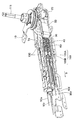
- reference numeral 1 denotes an endoscope, an insertion portion 2 to be inserted into a subject, an operation portion 3 connected to the proximal end of the insertion portion 2, and extended from the operation portion 3.
- the main part is composed of a universal cord 8 and a connector 9 provided at the extended end of the universal cord 8.
- the connector 9 of the universal cord 8 is provided with various bases and various electrical contacts (not shown), and external devices such as a video processor and a light source device are electrically connected.
- the up / down bending operation mechanism 100B is disposed above the left / right bending operation mechanism 100A with the chain separator 50 serving as a guide member interposed therebetween, and is a vertical bending sprocket that is a rotating body that is rotatable with respect to the support shaft 111. 65 (see FIG. 3) and a chain 60 for bending up and down, which is a long member wound around the sprocket 65.
- An upper bending wire 90u fixed to the tip of the bending portion 2w is connected to one end of the chain 60, and a lower bending wire fixed to the tip of the bending portion 2w is connected to the other end.
- a wire 90d is connected.
- a plate-like upper chain cover 70 is disposed on the upper surface of the up / down bending operation mechanism 100B.
- These two shaft bodies 112A and 112B are arranged so as to be independently rotatable.
- a bending operation knob 6 for bending left and right is fixed to the upper part of the shaft body 112A, and a sprocket 45 for bending left and right is fixed to the lower part.
- the shaft body 112B outside the shaft body 112A is provided with a bending operation knob 4 for bending up and down at the top and a sprocket 65 for bending up and down at the bottom.
- a fixing structure as shown in FIG. 4 may be employed to fix the support shaft 111 to the main frame 20.
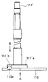
- the flat connection plate 113 is fixed to the end of the support shaft 111 ′ by caulking, and then the connection plate 113 is fixed to the main frame 20 ′.
- the screw 114 as a fixing tool is fastened and fixed.
- a flange portion 111′a is provided at the shaft end of the support shaft 111 ′ for positioning the support shaft 111 ′ and the connection plate 113 with respect to the main frame 20 ′. Positioning in the circumferential direction is performed by fitting a protrusion 113a provided on the connection plate 113 into a recess 111'b provided at a predetermined position of the flange portion 111'a.
- the support shaft 111 ′ is fixed to the main frame 20 ′, the axial positions of the support shaft 111 ′ and the connecting plate 113 are aligned from the A direction, and then the line of sight is reversed to support the support shaft 111 from the B direction. Align the circumferential position of the recess 111'b with the projection 113a of the connection plate 113, and return the line of sight to the A direction to crimp the support shaft 111 'to the connection plate 113, and then fix the support shaft 111'
- the connecting plate 113 is fastened and fixed to the main frame 20 ′ with screws 114. In such a fixing operation, the visual line direction to be viewed is reversed, so that the operator needs to perform the assembly operation by inverting the assembly part or changing his / her posture, and the work efficiency deteriorates.
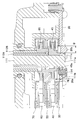
- the support shaft 111 in the present embodiment is provided with a flange portion 111 a at the lower end of the shaft, and this flange portion 111 a is used as a constituent member of the bending operation mechanism 100 of the main frame 20.
- the structure is such that the screw 114 is directly fastened and fixed to the lower surface side opposite to the upper surface side to be arranged.
- the flange 111a of the support shaft 111 is provided with a hole 111b through which a fastening screw 114 is inserted and a circumferential positioning hole 111c that are close to the outer peripheral surface of the support 111. ing. Further, with respect to the flange portion 111a of the support shaft 111, a female screw portion 20a to which a screw 114 is fastened is provided on the lower surface side of the main frame 20, and a protrusion 20b fitted into the hole portion 111c has a circumferential direction. It is projected for positioning.
- the sprocket 45 arranged on the upper surface of the main frame 20 has a small-diameter portion 45b formed by notching the tip side of the protruding portion 45a protruding from the boss portion and contacting the upper surface of the main frame 20 in the circumferential direction.
- the height Hj in the axial direction of the small diameter portion 45b is set to a height at which the tip end of the screw 114 does not contact.
- the mounting position of the screw 114 is set so that the tip end of the screw 114 is within a range D determined by the outer peripheral portion of the protruding portion 45a and the rotation trajectory of the connecting pin 40a of the chain 40.
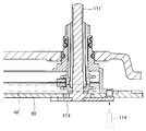
- the above-described fixing structure between the support shaft 111 and the main frame 20 can also be applied to a bending operation mechanism in which a bending operation wire is wound around a pulley and pulled without using a chain.
- the pulley 115 for bending operation interposed on the support shaft 111 ′′ is erected on both sides of the winding portion 115a around which the wire 90 ′ is wound and the winding portion 115a.
- a flange portion 115b serving as a guide for the wire 90 '.
- an escape portion 115c that forms an annular recess in the axial direction of the support shaft 111 ′′ on the inner diameter side of the winding portion 115a.
- the relief portion 115c is formed so that the tip end portion of the screw 114 is accommodated when the flange portion 111a ′′ of the support shaft 111 ′′ is fastened and fixed to the main frame 20 ′′ with the screw 114.
- various tubes and electric cables extending from the universal cord 8 for example, air supply / water supply / suction
- the control circuit is housed in the switch 11 provided in the operation unit main body 3h and the board case 85.
- the tube 81 is used for such applications, and electrical cables 82, 83, 84 such as an imaging cable are built in.
- Various members such as a flexible substrate 86 for connecting the substrate are arranged.
- the ground terminal 87 is arranged at a position away from the built-in members such as the tube 81, the electric cable 82, the flexible board 86, and the like, and is fastened and fixed to the main frame 20 with screws 88.
- the ground terminal 87 is scraped with one finger or the like while paying attention to the tube 81, the electric cable 82, the flexible board 86, and the like. It is necessary to secure a space for placement and maintain the state, and then place the ground terminal 87 at a predetermined position on the main frame 20 with the other hand and fasten and fix it with screws 88.
- the fixing work of the ground terminal 87 is not only complicated, but also the earth terminal when working with the electric screwdriver. It was not easy to hold 87 by hand. If the force for holding the grounding terminal 87 is not sufficient, the grounding terminal 87 may rotate together with the electric screwdriver and may damage surrounding members, so the work of fixing the grounding terminal 87 using the electric screwdriver is extremely careful. It is a necessary work.
- the terminal mounting portion 20c to which the ground terminal 87 of the main frame 20 is mounted has a seat surface wider than the outer shape of the ground terminal 87, and the ground terminal 87 is rotated and moved in the vicinity thereof.
- An anti-rotation portion 20d that protrudes in a convex or wall shape is provided as a detent that restricts the rotation.
- the anti-rotation portion 20 d is formed with a height that is equal to or greater than the plate thickness of the ground terminal 87.
- the ground terminal 87 can be easily held by hand against the rotational torque of the electric driver, and the assembling work can be performed while positioning, so that the assembling work can be easily and quickly performed. Further, since the height of the anti-rotation portion 20d is equal to or greater than the plate thickness of the ground terminal 87, the built-in member disposed in the periphery moves above the ground terminal 87, and the ground terminal 87 is another member. It is possible to prevent damage to other members without being caught in the gap.
- the anti-rotation portion 20d is an anti-rotation when the ground terminal 87 is fastened with the screw 88, but the anti-rotation portion is not only in the direction of tightening the screw but also in the direction of loosening the screw. May be provided.
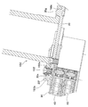
- the cord fastener 150 is a gate-like member that connects the main frame 20 and the base 8a of the universal cord 8 base, and has a plurality of screws on the hand side of the lower surface of the main frame 20, and a screw 130 in this embodiment. , 131, 132 are fixed by screws.
- the main frame 20 has a necessary minimum thickness for weight reduction and cost reduction. For this reason, when the cord fastener 150 is fastened and fixed with the screws 130 to 132, the tip portions of the screws 130 to 132 protrude from the main frame 20, and interference between the tip portions of some screws and the lower chain cover 30 occurs. Is concerned. If measures such as making a hole in the lower chain cover 30 are taken in order to avoid interference with the lower chain cover 30, the chain 40 that slides and moves on the lower chain cover 30 may have a hole edge or a protruding screw tip. There is a risk of getting caught in the part and hindering movement.
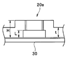
- the screw receiving portion 20e of the main frame 20 is not provided with a female screw portion on a simple cylindrical protruding portion formed by burring of a sheet metal or the like, but is formed with a protruding structure as shown in FIG. Yes. That is, in the protruding structure by burring, it is difficult to uniformly control the protruding height, and the length of the female screw portion varies.
- the screw receiving portion 20e in the present embodiment is protruded from the lower surface side (the cord fastener 150 side) of the main frame 20 by pressing or the like of the sheet metal material, and the upper surface side (lower chain) of the main frame 20 It is formed in a cup-shaped stepped shape that is recessed from the cover 30 side toward the lower surface side, and ensures the dimensional accuracy of each part.
- the cup-shaped bottom portion in which the screw hole is formed can be formed smoothly, and the difference between the thickness of the bottom portion, that is, the protrusion height H of the screw receiving portion 20e and the depth L of the recess (HL). ) Can be formed to be equal to the plate thickness t of the main frame 20, and the necessary screw hole depth can be ensured uniformly and accurately while maintaining the minimum plate thickness.
- the depth L of the recess of the screw receiving portion 20e is formed such that the tip of the screw 130 does not protrude from the main frame 20 with respect to the length under the neck of the screw 130 to be used. Interference between the tip portion and the lower chain cover 30 can be reliably avoided.
- the cord fastener 150 when the cord fastener 150 is attached to the main frame 20, the cord fastener 150 is positioned by fitting the projections 20f and 20g protruding from the main frame 20 with the openings 150b and 150c of the cord fastener 150.
- the convex portion 20g of the main frame 20 is fitted into the opening 150c of the cord fastener 150 provided between the screw 130 and the screw 131, and the convex portion 20f of the main frame 20 is provided in the vicinity of the mounting position of the screw 132.
- the cord fastener 150 is fitted into the opening 150b.
- the workability of assembling can be improved by adopting a temporary fixing structure as exemplified in FIGS.
- These temporary fixing structures can also be applied to the connection plate 113 when the connection plate 113 is used for fixing the spindle of the main frame 20.
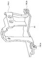
- a cord fastener 150_1 having a temporarily fixed structure illustrated in FIG. 12 has a U-shaped cross-section that can be manufactured by molding rather than sheet metal or cutting, and can be temporarily fixed by being hooked to the main frame 20 in the thickness direction.
- a hook 150_1a is provided.
- the hook 150_1a is formed not only in one direction but also in a plurality of directions such as vertically and horizontally, and is assembled so that the cord fastener 150_1 is inserted into the main frame 20.
- the cord fastener 150_3 illustrated in FIG. 14 is obtained by partially changing a conventional cord metal cord fastener and bending the hook 150_3a similar to the hook 150_1a of the cord fastener 150_1 described above. is there.
- the cord fastener 150_3 when the main frame 20 is not changed, it is limited to provide the hooks 150_3a at two places because of the shape restriction.
Abstract
Description
Claims (6)
- 被検体内に挿入される挿入部と、
前記挿入部に連設され、操作者が操作して前記挿入部の先端を動作させる操作部と、
前記操作部内に配設され、前記操作部に固定される板状のフレームと、
前記操作部内に配設され、前記操作部の操作により前記挿入部の先端を動作させる長尺部材と、
前記フレーム上に配設され、前記長尺部材が走行する部分を覆うカバー部材と、
前記フレームの前記カバ-部材と反対側で前記操作部内に配設される部材を保持する留め具と、
前記フレームに前記留め具を固定する固定具と、
前記フレームに前記固定具の受け部として形成され、前記フレームの前記留め具に面する側から突出されると共に前記カバー部材に面する側で凹形状に形成される受け部と、
を備えることを特徴とする挿入機器。 - 前記固定具は、前記受け部に螺合される雄ねじ部を有するビスであり、前記受け部は、前記ビスの雄ねじ部が螺合される雌ねじ部を有することを特徴とする請求項1記載の挿入機器。
- 前記受け部は、前記フレームの板厚を保って前記留め具に面する側で突出される共に前記カバー部材に面する側で凹形状に形成されることを特徴とする請求項1又は2記載の挿入機器。
- 前記留め具に、前記フレームから離間する方向に凹部を形成し、該凹部に前記固定具受け部を収納することを特徴とする請求項1記載の挿入機器。
- 前記留め具は、前記操作部内に挿通される電気ケーブルを保持することを特徴とする請求項1記載の挿入機器。
- 前記フレームに、前記電気ケーブルのアース端子を取り付ける端子取付部と、前記アース端子の回転移動を規制する回り止め部とを設けたことを特徴とする請求項5記載の挿入機器。
Priority Applications (4)
| Application Number | Priority Date | Filing Date | Title |
|---|---|---|---|
| JP2015546362A JP5985072B2 (ja) | 2014-03-04 | 2015-02-24 | 挿入機器 |
| EP15758041.6A EP3114981A4 (en) | 2014-03-04 | 2015-02-24 | Insertion instrument |
| CN201580011628.4A CN106102543B (zh) | 2014-03-04 | 2015-02-24 | 插入设备 |
| US15/254,084 US20160367112A1 (en) | 2014-03-04 | 2016-09-01 | Insertion instrument |
Applications Claiming Priority (2)
| Application Number | Priority Date | Filing Date | Title |
|---|---|---|---|
| JP2014041945 | 2014-03-04 | ||
| JP2014-041945 | 2014-03-04 |
Related Child Applications (1)
| Application Number | Title | Priority Date | Filing Date |
|---|---|---|---|
| US15/254,084 Continuation US20160367112A1 (en) | 2014-03-04 | 2016-09-01 | Insertion instrument |
Publications (1)
| Publication Number | Publication Date |
|---|---|
| WO2015133330A1 true WO2015133330A1 (ja) | 2015-09-11 |
Family
ID=54055139
Family Applications (1)
| Application Number | Title | Priority Date | Filing Date |
|---|---|---|---|
| PCT/JP2015/055176 WO2015133330A1 (ja) | 2014-03-04 | 2015-02-24 | 挿入機器 |
Country Status (5)
| Country | Link |
|---|---|
| US (1) | US20160367112A1 (ja) |
| EP (1) | EP3114981A4 (ja) |
| JP (1) | JP5985072B2 (ja) |
| CN (1) | CN106102543B (ja) |
| WO (1) | WO2015133330A1 (ja) |
Families Citing this family (1)
| Publication number | Priority date | Publication date | Assignee | Title |
|---|---|---|---|---|
| WO2020223427A1 (en) * | 2019-05-01 | 2020-11-05 | Boston Scientific Scimed, Inc. | Chambered handle for a medical device |
Citations (6)
| Publication number | Priority date | Publication date | Assignee | Title |
|---|---|---|---|---|
| JPH10234654A (ja) * | 1997-02-27 | 1998-09-08 | Olympus Optical Co Ltd | 内視鏡 |
| JPH1176151A (ja) * | 1997-09-08 | 1999-03-23 | Olympus Optical Co Ltd | 内視鏡先端部 |
| JP2000168469A (ja) * | 1998-12-04 | 2000-06-20 | Sumitomo Wiring Syst Ltd | アース端子の共締め構造 |
| JP2006183827A (ja) * | 2004-12-28 | 2006-07-13 | Sharp Corp | 締結構造およびネジユニット並びに物品の組立て方法 |
| JP2009279148A (ja) * | 2008-05-21 | 2009-12-03 | Olympus Medical Systems Corp | 電子内視鏡装置 |
| WO2014065092A1 (ja) * | 2012-10-22 | 2014-05-01 | オリンパスメディカルシステムズ株式会社 | 内視鏡 |
Family Cites Families (1)
| Publication number | Priority date | Publication date | Assignee | Title |
|---|---|---|---|---|
| CN102469919B (zh) * | 2010-07-29 | 2014-07-09 | 奥林巴斯医疗株式会社 | 弯曲机构 |
-
2015
- 2015-02-24 WO PCT/JP2015/055176 patent/WO2015133330A1/ja active Application Filing
- 2015-02-24 JP JP2015546362A patent/JP5985072B2/ja active Active
- 2015-02-24 EP EP15758041.6A patent/EP3114981A4/en not_active Withdrawn
- 2015-02-24 CN CN201580011628.4A patent/CN106102543B/zh active Active
-
2016
- 2016-09-01 US US15/254,084 patent/US20160367112A1/en not_active Abandoned
Patent Citations (6)
| Publication number | Priority date | Publication date | Assignee | Title |
|---|---|---|---|---|
| JPH10234654A (ja) * | 1997-02-27 | 1998-09-08 | Olympus Optical Co Ltd | 内視鏡 |
| JPH1176151A (ja) * | 1997-09-08 | 1999-03-23 | Olympus Optical Co Ltd | 内視鏡先端部 |
| JP2000168469A (ja) * | 1998-12-04 | 2000-06-20 | Sumitomo Wiring Syst Ltd | アース端子の共締め構造 |
| JP2006183827A (ja) * | 2004-12-28 | 2006-07-13 | Sharp Corp | 締結構造およびネジユニット並びに物品の組立て方法 |
| JP2009279148A (ja) * | 2008-05-21 | 2009-12-03 | Olympus Medical Systems Corp | 電子内視鏡装置 |
| WO2014065092A1 (ja) * | 2012-10-22 | 2014-05-01 | オリンパスメディカルシステムズ株式会社 | 内視鏡 |
Non-Patent Citations (1)
| Title |
|---|
| See also references of EP3114981A4 * |
Also Published As
| Publication number | Publication date |
|---|---|
| US20160367112A1 (en) | 2016-12-22 |
| JPWO2015133330A1 (ja) | 2017-04-06 |
| CN106102543B (zh) | 2018-04-06 |
| EP3114981A4 (en) | 2018-03-28 |
| JP5985072B2 (ja) | 2016-09-06 |
| EP3114981A1 (en) | 2017-01-11 |
| CN106102543A (zh) | 2016-11-09 |
Similar Documents
| Publication | Publication Date | Title |
|---|---|---|
| US8591405B2 (en) | Bending operation device for endoscope and the endoscope | |
| US20200305686A1 (en) | Endoscope | |
| US20170086652A1 (en) | Endoscope insertion portion and endoscope | |
| EP1849398A2 (en) | Endoscope connector device, endoscope cable lead-out unit and encoscope device | |
| US20160231556A1 (en) | Endoscope | |
| EP2692277A1 (en) | Curving operation device of endoscope | |
| US10136800B2 (en) | Bending operation device and endoscope | |
| US10197784B2 (en) | Operation mechanism for insertion device and insertion device | |
| JPWO2012077626A1 (ja) | コネクター | |
| JP5033149B2 (ja) | 監視カメラおよび監視カメラの取付け方法 | |
| WO2016043139A1 (ja) | 内視鏡 | |
| JP5985072B2 (ja) | 挿入機器 | |
| US10165932B2 (en) | Insertion device and rotating tubular member | |
| JP5657843B1 (ja) | 内視鏡操作部構造 | |
| JPWO2014171275A1 (ja) | 基板接続構造 | |
| WO2015118705A1 (ja) | 内視鏡 | |
| US9636002B2 (en) | Endoscope | |
| US20170007106A1 (en) | Endoscope | |
| JP4183805B2 (ja) | 内視鏡 | |
| JP2007018817A (ja) | フットスイッチ | |
| JP6999037B2 (ja) | 内視鏡コネクタおよび内視鏡 | |
| JP6063732B2 (ja) | 内視鏡 | |
| JP5231197B2 (ja) | 内視鏡装置 | |
| JP2001061761A (ja) | 内視鏡の本体操作部 | |
| JP2009285310A (ja) | 内視鏡装置 |
Legal Events
| Date | Code | Title | Description |
|---|---|---|---|
| ENP | Entry into the national phase |
Ref document number: 2015546362 Country of ref document: JP Kind code of ref document: A |
|
| 121 | Ep: the epo has been informed by wipo that ep was designated in this application |
Ref document number: 15758041 Country of ref document: EP Kind code of ref document: A1 |
|
| REEP | Request for entry into the european phase |
Ref document number: 2015758041 Country of ref document: EP |
|
| WWE | Wipo information: entry into national phase |
Ref document number: 2015758041 Country of ref document: EP |
|
| NENP | Non-entry into the national phase |
Ref country code: DE |