WO2015132919A1 - Système de gazéification - Google Patents
Système de gazéification Download PDFInfo
- Publication number
- WO2015132919A1 WO2015132919A1 PCT/JP2014/055692 JP2014055692W WO2015132919A1 WO 2015132919 A1 WO2015132919 A1 WO 2015132919A1 JP 2014055692 W JP2014055692 W JP 2014055692W WO 2015132919 A1 WO2015132919 A1 WO 2015132919A1
- Authority
- WO
- WIPO (PCT)
- Prior art keywords
- raw material
- gasification
- heat exchanger
- temperature
- low temperature
- Prior art date
Links
Images


Classifications
-
- C—CHEMISTRY; METALLURGY
- C10—PETROLEUM, GAS OR COKE INDUSTRIES; TECHNICAL GASES CONTAINING CARBON MONOXIDE; FUELS; LUBRICANTS; PEAT
- C10J—PRODUCTION OF PRODUCER GAS, WATER-GAS, SYNTHESIS GAS FROM SOLID CARBONACEOUS MATERIAL, OR MIXTURES CONTAINING THESE GASES; CARBURETTING AIR OR OTHER GASES
- C10J3/00—Production of combustible gases containing carbon monoxide from solid carbonaceous fuels
- C10J3/72—Other features
- C10J3/86—Other features combined with waste-heat boilers
-
- C—CHEMISTRY; METALLURGY
- C10—PETROLEUM, GAS OR COKE INDUSTRIES; TECHNICAL GASES CONTAINING CARBON MONOXIDE; FUELS; LUBRICANTS; PEAT
- C10J—PRODUCTION OF PRODUCER GAS, WATER-GAS, SYNTHESIS GAS FROM SOLID CARBONACEOUS MATERIAL, OR MIXTURES CONTAINING THESE GASES; CARBURETTING AIR OR OTHER GASES
- C10J3/00—Production of combustible gases containing carbon monoxide from solid carbonaceous fuels
- C10J3/72—Other features
- C10J3/74—Construction of shells or jackets
- C10J3/76—Water jackets; Steam boiler-jackets
-
- C—CHEMISTRY; METALLURGY
- C10—PETROLEUM, GAS OR COKE INDUSTRIES; TECHNICAL GASES CONTAINING CARBON MONOXIDE; FUELS; LUBRICANTS; PEAT
- C10J—PRODUCTION OF PRODUCER GAS, WATER-GAS, SYNTHESIS GAS FROM SOLID CARBONACEOUS MATERIAL, OR MIXTURES CONTAINING THESE GASES; CARBURETTING AIR OR OTHER GASES
- C10J3/00—Production of combustible gases containing carbon monoxide from solid carbonaceous fuels
- C10J3/72—Other features
- C10J3/78—High-pressure apparatus
-
- F—MECHANICAL ENGINEERING; LIGHTING; HEATING; WEAPONS; BLASTING
- F28—HEAT EXCHANGE IN GENERAL
- F28D—HEAT-EXCHANGE APPARATUS, NOT PROVIDED FOR IN ANOTHER SUBCLASS, IN WHICH THE HEAT-EXCHANGE MEDIA DO NOT COME INTO DIRECT CONTACT
- F28D7/00—Heat-exchange apparatus having stationary tubular conduit assemblies for both heat-exchange media, the media being in contact with different sides of a conduit wall
- F28D7/10—Heat-exchange apparatus having stationary tubular conduit assemblies for both heat-exchange media, the media being in contact with different sides of a conduit wall the conduits being arranged one within the other, e.g. concentrically
- F28D7/14—Heat-exchange apparatus having stationary tubular conduit assemblies for both heat-exchange media, the media being in contact with different sides of a conduit wall the conduits being arranged one within the other, e.g. concentrically both tubes being bent
-
- C—CHEMISTRY; METALLURGY
- C10—PETROLEUM, GAS OR COKE INDUSTRIES; TECHNICAL GASES CONTAINING CARBON MONOXIDE; FUELS; LUBRICANTS; PEAT
- C10J—PRODUCTION OF PRODUCER GAS, WATER-GAS, SYNTHESIS GAS FROM SOLID CARBONACEOUS MATERIAL, OR MIXTURES CONTAINING THESE GASES; CARBURETTING AIR OR OTHER GASES
- C10J2300/00—Details of gasification processes
- C10J2300/09—Details of the feed, e.g. feeding of spent catalyst, inert gas or halogens
- C10J2300/0903—Feed preparation
- C10J2300/0906—Physical processes, e.g. shredding, comminuting, chopping, sorting
-
- C—CHEMISTRY; METALLURGY
- C10—PETROLEUM, GAS OR COKE INDUSTRIES; TECHNICAL GASES CONTAINING CARBON MONOXIDE; FUELS; LUBRICANTS; PEAT
- C10J—PRODUCTION OF PRODUCER GAS, WATER-GAS, SYNTHESIS GAS FROM SOLID CARBONACEOUS MATERIAL, OR MIXTURES CONTAINING THESE GASES; CARBURETTING AIR OR OTHER GASES
- C10J2300/00—Details of gasification processes
- C10J2300/09—Details of the feed, e.g. feeding of spent catalyst, inert gas or halogens
- C10J2300/0913—Carbonaceous raw material
- C10J2300/0916—Biomass
-
- C—CHEMISTRY; METALLURGY
- C10—PETROLEUM, GAS OR COKE INDUSTRIES; TECHNICAL GASES CONTAINING CARBON MONOXIDE; FUELS; LUBRICANTS; PEAT
- C10J—PRODUCTION OF PRODUCER GAS, WATER-GAS, SYNTHESIS GAS FROM SOLID CARBONACEOUS MATERIAL, OR MIXTURES CONTAINING THESE GASES; CARBURETTING AIR OR OTHER GASES
- C10J2300/00—Details of gasification processes
- C10J2300/09—Details of the feed, e.g. feeding of spent catalyst, inert gas or halogens
- C10J2300/0953—Gasifying agents
- C10J2300/0973—Water
- C10J2300/0979—Water as supercritical steam
-
- C—CHEMISTRY; METALLURGY
- C10—PETROLEUM, GAS OR COKE INDUSTRIES; TECHNICAL GASES CONTAINING CARBON MONOXIDE; FUELS; LUBRICANTS; PEAT
- C10J—PRODUCTION OF PRODUCER GAS, WATER-GAS, SYNTHESIS GAS FROM SOLID CARBONACEOUS MATERIAL, OR MIXTURES CONTAINING THESE GASES; CARBURETTING AIR OR OTHER GASES
- C10J2300/00—Details of gasification processes
- C10J2300/12—Heating the gasifier
- C10J2300/1246—Heating the gasifier by external or indirect heating
-
- C—CHEMISTRY; METALLURGY
- C10—PETROLEUM, GAS OR COKE INDUSTRIES; TECHNICAL GASES CONTAINING CARBON MONOXIDE; FUELS; LUBRICANTS; PEAT
- C10J—PRODUCTION OF PRODUCER GAS, WATER-GAS, SYNTHESIS GAS FROM SOLID CARBONACEOUS MATERIAL, OR MIXTURES CONTAINING THESE GASES; CARBURETTING AIR OR OTHER GASES
- C10J2300/00—Details of gasification processes
- C10J2300/18—Details of the gasification process, e.g. loops, autothermal operation
- C10J2300/1861—Heat exchange between at least two process streams
- C10J2300/1892—Heat exchange between at least two process streams with one stream being water/steam
-
- F—MECHANICAL ENGINEERING; LIGHTING; HEATING; WEAPONS; BLASTING
- F28—HEAT EXCHANGE IN GENERAL
- F28F—DETAILS OF HEAT-EXCHANGE AND HEAT-TRANSFER APPARATUS, OF GENERAL APPLICATION
- F28F2250/00—Arrangements for modifying the flow of the heat exchange media, e.g. flow guiding means; Particular flow patterns
- F28F2250/06—Derivation channels, e.g. bypass
-
- Y—GENERAL TAGGING OF NEW TECHNOLOGICAL DEVELOPMENTS; GENERAL TAGGING OF CROSS-SECTIONAL TECHNOLOGIES SPANNING OVER SEVERAL SECTIONS OF THE IPC; TECHNICAL SUBJECTS COVERED BY FORMER USPC CROSS-REFERENCE ART COLLECTIONS [XRACs] AND DIGESTS
- Y02—TECHNOLOGIES OR APPLICATIONS FOR MITIGATION OR ADAPTATION AGAINST CLIMATE CHANGE
- Y02P—CLIMATE CHANGE MITIGATION TECHNOLOGIES IN THE PRODUCTION OR PROCESSING OF GOODS
- Y02P20/00—Technologies relating to chemical industry
- Y02P20/10—Process efficiency
-
- Y—GENERAL TAGGING OF NEW TECHNOLOGICAL DEVELOPMENTS; GENERAL TAGGING OF CROSS-SECTIONAL TECHNOLOGIES SPANNING OVER SEVERAL SECTIONS OF THE IPC; TECHNICAL SUBJECTS COVERED BY FORMER USPC CROSS-REFERENCE ART COLLECTIONS [XRACs] AND DIGESTS
- Y02—TECHNOLOGIES OR APPLICATIONS FOR MITIGATION OR ADAPTATION AGAINST CLIMATE CHANGE
- Y02P—CLIMATE CHANGE MITIGATION TECHNOLOGIES IN THE PRODUCTION OR PROCESSING OF GOODS
- Y02P20/00—Technologies relating to chemical industry
- Y02P20/50—Improvements relating to the production of bulk chemicals
- Y02P20/54—Improvements relating to the production of bulk chemicals using solvents, e.g. supercritical solvents or ionic liquids
Definitions
- the present invention relates to a gasification system that gasifies a gasification raw material such as biomass using a heat exchanger.
- Patent Documents 1 and 2 disclose that water-containing biomass is supercritical water in a double-tube heat exchanger. A technique is disclosed in which the temperature is raised by heat exchange and the biomass is gasified by heating the biomass with a predetermined reactor or burner.
- the suspension containing biomass is heated from room temperature to a high temperature of about 400 ° C., for example. Moreover, the internal pressure of the heat exchanger at this time is high, for example, 25 MPa.
- This invention is made
- the objective is to provide the gasification system which improves the heat exchange efficiency in a heat exchanger, and, thereby, gasifies a gasification raw material efficiently. is there.
- the present invention introduces a supercritical state treated water that heats the gasified raw material by exchanging heat with the gasified raw material, and a low-temperature channel through which the gasified raw material flows.
- a counter-flow heat exchanger having a high-temperature side flow path, and the gasification raw material heated in the counter-flow heat exchanger is gasified into a supercritical state by heating and pressurizing, and the supercritical A gasification system comprising: a gasification reactor that discharges as treated water in a state; and a treated water passage that guides the treated water discharged from the gasification reactor to the counter-flow heat exchanger.
- the heated gasification raw material Characterized by and an external heating means for returning to the intermediate position of the material downstream of the position taken out.
- the gasification raw material introduced into the heat exchanger is taken out in the middle of the low temperature side flow path, and the taken gasification raw material is heated and returned to the raw material downstream side of the low temperature side flow path. It is possible to prevent the gasification raw material from flowing through the portion where the heat exchange efficiency is lowered, and thereby the heat exchange efficiency in the heat exchanger can be improved. Moreover, the gasification raw material can be efficiently gasified by heating the gasification raw material with an external heating means outside the heat exchanger.
- Another aspect of the present invention is characterized in that a position where the extraction is performed is determined based on a constant pressure specific heat value of the gasification raw material, and the gasification raw material is extracted from the determined position.
- the position at which extraction is performed is determined based on the constant pressure specific heat.
- the heat exchange efficiency is reliably improved by extracting the gasification raw material from the position of the heat exchanger having a low constant pressure specific heat value. Can do.
- the low-temperature side flow path includes a low-temperature zone in which the temperature of the gasification raw material introduced by the gasification raw material introduction means rises, and the gasification that has passed through the low-temperature zone.
- a high temperature zone where the temperature of the raw material rises again, and the external heating means takes out the gasified raw material from the high temperature end of the low temperature zone, and the gasified raw material to the low temperature end of the high temperature zone. It is characterized by returning.
- the gasification raw material is taken out from the high temperature end of the low temperature zone and returned to the low temperature end of the high temperature zone, so that the temperature of the gasification raw material can be reliably increased without circulating the temperature range where the heat exchange efficiency is low.
- gasification can be performed efficiently.
- the constant-pressure specific heat of the said gasification raw material in the position which performs the said taking-out shall be 10 kJ / kg * K or more, for example.
- Another aspect of the present invention is characterized in that the heating in the external heating means is performed in a preheater that preheats the gasified raw material heated in the counterflow heat exchanger.
- the energy generated in the gasification system can be efficiently used by heating the gasification raw material taken out from the counterflow heat exchanger with the preheater.
- the present invention it is possible to provide a gasification system that improves the heat exchange efficiency in the heat exchanger and thereby efficiently gasifies the gasification raw material.
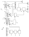
- FIG. 1 is a diagram illustrating a schematic configuration of a biomass gasification system 100 using supercritical water.
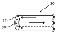
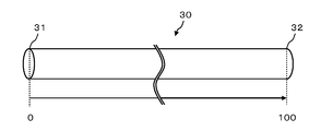
- FIG. It is a figure explaining an example of the composition of the double tube in heat exchanger. It is the figure which showed the heat exchanger 30 when the length of the double tube from the inlet 31 of a gasification raw material to the discharge port 32 is set to 100.
- FIG. 6 is a diagram illustrating an example of a change in the temperature of the gasification raw material flowing through the low temperature side flow path 36 (“tube temperature”) and a change in the temperature of the treated water flowing through the high temperature side flow path 37 (“jacket temperature”).
- FIG. It is the figure which showed the relationship between temperature, a pressure, and a constant pressure specific heat.
- the heat exchanger 30 comprised so that the intermediate temperature area 72 may not exist. It is a figure explaining the figure explaining the position of the heat exchanger 30 suitable as the taking-out position 33 and the return flow position. It is the figure which showed the relationship between temperature, a pressure, and a constant pressure specific heat.
- FIG. 1A is a diagram illustrating a schematic configuration of a biomass gasification system 100 using supercritical water, which is described as an embodiment of the present invention.
- the gasification system 100 includes a regulating tank 1, a crusher 2, a supply pump 3, a heat exchanger 30, a preheater 40, a gasification reactor 50, a cooler 51, a decompressor 52, a gas-liquid.
- a separator 60, a gas tank 61, and the like are provided.
- the heat exchanger 30 and the gasification reactor are connected by a pipe 55.
- the adjustment tank 1 is a tank that mixes biomass, water, and activated carbon while adjusting the mixing amount of water and activated carbon according to the type, amount, moisture content, and the like of the biomass.
- the gasification raw material (suspension) is prepared by mixing biomass, activated carbon, and water.
- the said biomass is hydrous biomass, such as shochu residue and egg-collecting chicken droppings, for example.
- other nonmetallic catalysts may be mixed in place of activated carbon, for example, zeolite or a mixture thereof may be used.
- the crusher 2 crushes the biomass in the suspension prepared in the adjustment tank 1 so that the biomass has a uniform size (preferably an average particle size of 500 ⁇ m or less, more preferably an average particle size of 300 ⁇ m or less).
- the supply pump 3 is a device that supplies the suspension supplied from the crusher 2 to the exchanger 30.
- the supply pump 3 is, for example, a high-pressure pump or a Mono pump.
- the heat exchanger 30 is a counter-flow heat exchanger, and is discharged from the gasification reactor 50 (product gas and ash discharged from the gasification reactor 50, non-metallic catalyst and water ( This is a device for raising the temperature of the gasification raw material (suspension) supplied from the supply pump 3 by using heat of supercritical water) or the like. That is, the heat exchanger 30 includes a low temperature side flow path 36 through which the gasification raw material supplied from the supply pump 3 flows and a high temperature side flow path 37, and the high temperature side flow path 37 includes the low temperature side flow path 36.
- the treated water for raising the temperature of the gasification raw material flows by exchanging heat with the gasification raw material flowing through
- the waste (treated water) is introduced into the high temperature side channel 37 through the pipe 55.
- the suspension introduced from the inlet 31 is heated while flowing through the low-temperature channel 36 and discharged from the outlet 32.
- the internal pressure of the heat exchanger 30 is set to about 25 MPa.
- the heat exchanger 30 is, for example, a double tube heat exchanger.
- FIG. 1B is a diagram illustrating an example of the configuration of a double tube in the heat exchanger 30. As shown in the figure, the low temperature side flow path 36 is provided as an inner pipe of a double pipe, and the high temperature side flow path 37 is provided as an outer pipe of the double pipe.
- the preheater 40 is a device that heats the suspension to a predetermined temperature by burning generated gas, fuel gas (for example, LPG), oxygen gas, and the like stored in the gas tank 61.
- the gasification reactor 50 is, for example, a tubular reactor, a fluidized bed reactor, or the like, and is a device that gasifies biomass in suspension with supercritical water. This gasification is performed using the nonmetallic catalyst at a temperature and pressure (for example, 600 ° C. or more and in the range of 25 to 35 MPa) that can increase the reaction efficiency.
- a temperature and pressure for example, 600 ° C. or more and in the range of 25 to 35 MPa
- the cooler 51 is a device for cooling the discharge discharged from the gasification reactor 50.
- the decompressor 52 is a device that depressurizes the pressure of the product gas of the exhaust discharged from the gasification reactor 50.
- the gas-liquid separator 60 is an apparatus that separates the effluent discharged from the gasification reactor 50 into a gas component (product gas) and a liquid component (mixed solution containing ash, activated carbon, and water).
- the gas tank 61 is a container (preferably a pressure-resistant container) that stores a gas component (product gas) separated by the gas-liquid separator 60.
- a heater 62 provided in the gasification reactor 50 combusts a part of the product gas stored in the gas tank 61 or a fuel gas (for example, LPG) in a gas containing oxygen to cause the gasification reactor 50 to flow.
- a device for heating and heating the suspension to a predetermined temperature The heater 63 provided in the preheater 40 heats the preheater 40 by burning a part of the generated gas stored in the gas tank 61 or a fuel gas (for example, LPG) in a gas containing oxygen.
- the heaters 62 and 63 are existing apparatuses that burn and heat fuel gas, such as a burner, for example.
- the water flowing through the high temperature side channel 37 of the heat exchanger 30 is the supercritical state treated water discharged from the gasification reactor 50 as described above, and its temperature Is, for example, as high as about 600 ° C.
- the internal pressure of the heat exchanger 30 is also as high as 25 MPa. Under such high-temperature and high-pressure conditions, the gasification raw material may not be sufficiently heated in the heat exchanger 30.
- FIG. 3 shows the gasification raw material flowing through the low-temperature channel 36 when the heat exchanger 30 (see FIG. 2) is used, where the total length of the double pipe from the inlet 31 to the outlet 32 is 100.
- FIG. 6 is a diagram showing an example of a change in temperature (“tube temperature”) and a change in the temperature of treated water flowing through the high temperature side channel 37 (“jacket temperature”). As shown in the figure, when about 600 ° C. treated water is introduced into the heat exchanger 30, the heat exchanger 30 has a low-temperature zone in the order in which the gasification raw material flows (in order from the inlet 31). 71, medium temperature area 72, and high temperature area 73 are formed.
- the temperature of the gasification raw material introduced from the inlet 31 rapidly rises from about 25 ° C. to about 380 ° C., but in the intermediate temperature zone 72, the temperature of the gasification raw material falls within a predetermined range. Almost no increase (remains at about 380 ° C.). In the high temperature zone 73, the temperature of the gasification raw material rises again and rapidly reaches about 400 ° C.
- the temperature of the gasification raw material rises rapidly in the low temperature zone 71 and the high temperature zone 73, but the temperature of the gasification raw material hardly rises in the medium temperature zone 72, and the heat exchange process in the heat exchanger 30 is entirely performed.
- the heat exchange efficiency of the heat exchanger 30 is particularly lowered.
- FIG. 4 is a diagram showing the relationship between water temperature, pressure, and constant pressure specific heat.
- the constant pressure specific heat takes a specific high value around 380 ° C. (peaks), so that the gasification raw material at such temperature rises. It is hard to be heated.
- the constant-pressure specific heat peaks at about 380 ° C., as in the case of the gasification raw material (exactly, because of the pressure loss in the double pipe, Peak at a slightly lower temperature).
- the inventors of the present invention have made sure that there is no zone in the heat exchanger 30 where the temperature of the gasification raw material is difficult to rise (in the above example, the zone where the temperature of the gasification raw material is about 380 ° C.). It was conceived that the heat exchange efficiency in the heat exchanger 30 can be improved by configuring the heat exchanger 30 so that the section 72 does not exist.
- FIG. 30 An example of the heat exchanger 30 having such a configuration is shown in FIG.
- an external heating means 35 for heating the gasification raw material is provided outside the heat exchanger 30. That is, as shown by reference numeral 35a, the gasified raw material is taken out from a predetermined position 33 (hereinafter referred to as take-out position 33) of the low temperature side flow path 36, and as shown by reference numeral 35b, the taken out gasified raw material is preheated. As shown by reference numeral 35 c, the heated gasified raw material is heated at 40, and the heated gasified raw material is located at a predetermined position 34 (hereinafter referred to as a return position 34) of the low-temperature channel 36 on the downstream side of the raw material.
- a predetermined position 33 hereinafter referred to as take-out position 33
- the flow path has been changed to return.
- the flow path is changed by connecting the take-out position 33 and the preheater 40 with a pipe to circulate the gasification raw material, and connecting the preheater 40 and the return position 34 with a pipe for gasification. This is done by distributing the raw materials.
- the above-described take-out position 33 and return position 34 are specifically the following positions. That is, as shown in FIG. 5, the take-out position 33 is a position where the temperature Tc of the gasification raw material is 370 ° C. and the temperature Td of the treated water is 375 ° C. (that is, the high temperature end of the low temperature area 71 and the intermediate temperature area 72. Boundary).
- the return flow position 34 is a position where the temperature Te of the gasification raw material becomes 385 ° C. and the temperature Tf of the treated water becomes 390 ° C. (that is, the boundary between the low temperature end of the high temperature zone 73 and the intermediate temperature zone 72).
- the flow path of the high temperature side flow path 37 is also changed according to such a flow path change of the low temperature side flow path 36. That is, as shown in FIG. 5, the take-out position 33 and the return position 34 are connected by a bypass pipe 38 so that the treated water flows directly from the return position 34 to the take-out position 33. Moreover, the surplus part 39 of piping is excised by the above flow path change.
- the take-out position 33 is determined at the boundary between the low temperature region 71 and the intermediate temperature region 72, and the return flow position 34 is determined at the boundary between the intermediate temperature region 72 and the high temperature region 73.
- the heat exchange efficiency in the vessel 30 can be improved and the temperature of the gasification raw material can be reliably increased.
- region which becomes about 380 degreeC which is the temperature where the heat exchange rate of a fluid becomes low does not exist.
- tar is generated in the double pipe, and the inner pipe (low temperature side flow path 36) and the outer pipe (high temperature side flow path 37) are likely to be blocked.
- the pipe can be changed by changing the flow path so as to omit the intermediate temperature zone 72 as described above. Various expenses related to maintenance of the project can be reduced.
- the gasification raw material taken out from the heat exchanger 30 is heated by the preheater 40, the energy efficiency in the gasification system 100 can be improved. Moreover, it is not necessary to introduce new heating equipment, and the cost can be prevented from increasing.
- the position where the temperature of the gasification raw material is about 370 ° C. is the take-out position 33 and the position where the gasification raw material is about 385 ° C. is the return flow position 34.
- the position 34 is not limited to these positions. That is, the take-out position 33 may be a boundary between the low temperature zone 71 and the medium temperature zone 72, and the return flow position 34 may be a boundary between the medium temperature zone 72 and the high temperature zone 73.
- FIG. 6 is a diagram for explaining the position of the heat exchanger 30 suitable as the take-out position 33 and the return position 34.
- the take-out position 33 is compared in the vicinity of the portion where the constant pressure specific heat of the gasification raw material has a peak value on the side close to the inlet 31 (the portion where the temperature of the gasification raw material is about 380 ° C.) It may be anywhere in the position where the specific heat at the specific pressure is high (for example, the range indicated by reference numerals 33a to 33b).
- the position is such that the constant pressure specific heat is 10 kJ / kg ⁇ K or more.
- the return flow position 34 has a relatively constant pressure specific heat at a position near the discharge port 32 where the constant pressure specific heat of the gasification raw material reaches a peak value (a position where the temperature of the gasification raw material reaches about 380 ° C.). It may be anywhere in the high position (for example, the range indicated by reference numeral 34a to reference numeral 34b). For example, the position is such that the constant pressure specific heat is 10 kJ / kg ⁇ K or more.
- the internal pressure of the heat exchanger 30 is 25 MPa, but the internal pressure of the heat exchanger 30 may change. If the internal pressure changes, the temperature of the constant pressure specific heat peak also changes (see FIG. 4). Therefore, when the internal pressure of the heat exchanger 30 changes, it is preferable to adjust the take-out position 33 accordingly.
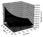
- FIG. 7 is a diagram showing the relationship between water temperature, pressure, and constant-pressure specific heat used to determine the take-out position 33.
- the curved surface 74 represents a set of temperature / pressure plots in which the constant pressure specific heat exceeds a predetermined value.
- the heat exchange efficiency in the heat exchanger 30 can be improved by determining the take-out position 33 and the return flow position 34 based on the value of the constant pressure specific heat. Can be improved.
- the gasification raw material introduced into the heat exchanger 30 is taken out in the middle of the low temperature side flow path 36, and the taken out gasification raw material is heated.
- the gasification raw material can be efficiently gasified by heating the gasification raw material with an external heating means (preheater 40) outside the heat exchanger 30. Further, it is not necessary to newly introduce a heating facility, and the cost can be prevented from increasing.
- the heat exchange efficiency is reliably improved by extracting the gasification raw material from the position of the heat exchanger 30 where the constant pressure specific heat is low. Can do.
- the gasification raw material is taken out from the boundary portion between the low temperature zone 71 and the intermediate temperature zone 72 and returned to the boundary portion between the intermediate temperature zone 72 and the high temperature zone 73, the intermediate temperature zone 72 having low heat exchange efficiency is not circulated.
- the temperature of the gasification raw material can be reliably increased, and thereby gasification can be performed efficiently.
- a double-pipe heat exchanger is taken up as the heat exchanger 30, but other types of heat exchangers may be used as long as they are counterflow type heat exchangers.
- the method of using the preheater 40 which is an existing facility as a means for heating the gasification raw material taken out from the take-out position 33 has been described.
- an external heating means a heater or the like
Landscapes
- Chemical & Material Sciences (AREA)
- Engineering & Computer Science (AREA)
- Combustion & Propulsion (AREA)
- Oil, Petroleum & Natural Gas (AREA)
- Organic Chemistry (AREA)
- Physics & Mathematics (AREA)
- Thermal Sciences (AREA)
- Mechanical Engineering (AREA)
- General Engineering & Computer Science (AREA)
- Processing Of Solid Wastes (AREA)
Abstract
Priority Applications (6)
| Application Number | Priority Date | Filing Date | Title |
|---|---|---|---|
| SG11201607310WA SG11201607310WA (en) | 2014-03-05 | 2014-03-05 | Gasification system |
| US15/123,316 US20170073594A1 (en) | 2014-03-05 | 2014-03-05 | Gasification system |
| JP2016506029A JP6060350B2 (ja) | 2014-03-05 | 2014-03-05 | ガス化システム |
| EP14884947.4A EP3115442A4 (fr) | 2014-03-05 | 2014-03-05 | Système de gazéification |
| MYPI2016703201A MY173498A (en) | 2014-03-05 | 2014-03-05 | Gasification system |
| PCT/JP2014/055692 WO2015132919A1 (fr) | 2014-03-05 | 2014-03-05 | Système de gazéification |
Applications Claiming Priority (1)
| Application Number | Priority Date | Filing Date | Title |
|---|---|---|---|
| PCT/JP2014/055692 WO2015132919A1 (fr) | 2014-03-05 | 2014-03-05 | Système de gazéification |
Publications (1)
| Publication Number | Publication Date |
|---|---|
| WO2015132919A1 true WO2015132919A1 (fr) | 2015-09-11 |
Family
ID=54054755
Family Applications (1)
| Application Number | Title | Priority Date | Filing Date |
|---|---|---|---|
| PCT/JP2014/055692 WO2015132919A1 (fr) | 2014-03-05 | 2014-03-05 | Système de gazéification |
Country Status (5)
| Country | Link |
|---|---|
| US (1) | US20170073594A1 (fr) |
| EP (1) | EP3115442A4 (fr) |
| JP (1) | JP6060350B2 (fr) |
| SG (1) | SG11201607310WA (fr) |
| WO (1) | WO2015132919A1 (fr) |
Families Citing this family (4)
| Publication number | Priority date | Publication date | Assignee | Title |
|---|---|---|---|---|
| DK3592831T3 (da) | 2017-03-07 | 2021-06-21 | Steeper Energy Aps | Varme- og kølefremgangsmåde til et højtryksbehandlingssystem |
| RU2679330C1 (ru) * | 2017-12-01 | 2019-02-07 | Федеральное государственное бюджетное научное учреждение Федеральный научный агроинженерный центр ВИМ (ФГБНУ ФНАЦ ВИМ) | Энергетический комплекс на основе газификации отходов биомассы |
| WO2020169888A1 (fr) * | 2019-02-21 | 2020-08-27 | Teknologian Tutkimuskeskus Vtt Oy | Procédé et agencement de traitement pour la production d'hydrocarbures et leur utilisation |
| CL2022003203A1 (es) * | 2022-11-16 | 2023-04-14 | Univ De Tarapaca | Reactor de pirólisis para tratamiento por lote de residuos urbanos |
Citations (5)
| Publication number | Priority date | Publication date | Assignee | Title |
|---|---|---|---|---|
| JPH1126242A (ja) * | 1997-07-07 | 1999-01-29 | Toko Inc | 小型インダクタ用コアとその製造方法 |
| JP2001115174A (ja) * | 1999-10-15 | 2001-04-24 | Toshiba Corp | 燃料処理システム |
| JP2008249207A (ja) * | 2007-03-29 | 2008-10-16 | Hiroshima Univ | バイオマスガス化発電システム |
| JP2009149773A (ja) * | 2007-12-20 | 2009-07-09 | Hiroshima Univ | バイオマスガス化方法、及びバイオマスガス化システム |
| JP2010174189A (ja) * | 2009-01-30 | 2010-08-12 | Hiroshima Univ | 燃料ガス製造方法 |
Family Cites Families (18)
| Publication number | Priority date | Publication date | Assignee | Title |
|---|---|---|---|---|
| US5252224A (en) * | 1991-06-28 | 1993-10-12 | Modell Development Corporation | Supercritical water oxidation process of organics with inorganics |
| US6066263A (en) * | 1995-04-20 | 2000-05-23 | Tohoku Electric Power Company, Inc. | Apparatus for converting waste plastic into oil |
| US6017460A (en) * | 1996-06-07 | 2000-01-25 | Chematur Engineering Ab | Heating and reaction system and method using recycle reactor |
| US6047768A (en) * | 1997-05-06 | 2000-04-11 | United States Filter Corporation | Process and apparatus for treating waste |
| JPH11262742A (ja) * | 1998-03-19 | 1999-09-28 | Ube Ind Ltd | 廃棄物の処理方法および処理装置 |
| JP3057250B2 (ja) * | 1998-11-18 | 2000-06-26 | 財団法人石炭利用総合センター | 有機廃棄物の処理方法 |
| US8038743B1 (en) * | 2002-11-27 | 2011-10-18 | Drs Sustainment Systems, Inc. | Systems and methods for supercritical water reformation of fuels and generation of hydrogen using supercritical water |
| US7186345B2 (en) * | 2003-05-06 | 2007-03-06 | Engineered Support Systems, Inc. | Systems for water purification through supercritical oxidation |
| US20090159498A1 (en) * | 2007-12-20 | 2009-06-25 | Chevron U.S.A. Inc. | Intergrated process for in-field upgrading of hydrocarbons |
| US20090166261A1 (en) * | 2007-12-28 | 2009-07-02 | Chevron U.S.A. Inc. | Upgrading heavy hydrocarbon oils |
| US20090166262A1 (en) * | 2007-12-28 | 2009-07-02 | Chevron U.S.A. Inc. | Simultaneous metal, sulfur and nitrogen removal using supercritical water |
| US7955508B2 (en) * | 2008-03-11 | 2011-06-07 | Xtrudx Technologies, Inc. | Supercritical fluid biomass conversion systems |
| JP5688723B2 (ja) * | 2008-03-31 | 2015-03-25 | 国立大学法人広島大学 | バイオマス付着防止方法 |
| NL1039006C2 (en) * | 2011-08-26 | 2013-02-27 | Klaas Gerrit Smit | A process for the gasification of wet biomass. |
| NL1039007C2 (en) * | 2011-08-26 | 2013-02-27 | Klaas Gerrit Smit | A process and a reaction apparatus for the gasification of wet biomass. |
| US10144874B2 (en) * | 2013-03-15 | 2018-12-04 | Terrapower, Llc | Method and system for performing thermochemical conversion of a carbonaceous feedstock to a reaction product |
| US9376639B2 (en) * | 2013-03-15 | 2016-06-28 | Terrapower, Llc | Method and system for performing gasification of carbonaceous feedstock |
| US9732292B2 (en) * | 2013-03-20 | 2017-08-15 | Empire Technology Development Llc | Corrosion reduction for supercritical water gasification through seeded sacrificial metal |
-
2014
- 2014-03-05 US US15/123,316 patent/US20170073594A1/en not_active Abandoned
- 2014-03-05 WO PCT/JP2014/055692 patent/WO2015132919A1/fr active Application Filing
- 2014-03-05 EP EP14884947.4A patent/EP3115442A4/fr not_active Withdrawn
- 2014-03-05 SG SG11201607310WA patent/SG11201607310WA/en unknown
- 2014-03-05 JP JP2016506029A patent/JP6060350B2/ja active Active
Patent Citations (5)
| Publication number | Priority date | Publication date | Assignee | Title |
|---|---|---|---|---|
| JPH1126242A (ja) * | 1997-07-07 | 1999-01-29 | Toko Inc | 小型インダクタ用コアとその製造方法 |
| JP2001115174A (ja) * | 1999-10-15 | 2001-04-24 | Toshiba Corp | 燃料処理システム |
| JP2008249207A (ja) * | 2007-03-29 | 2008-10-16 | Hiroshima Univ | バイオマスガス化発電システム |
| JP2009149773A (ja) * | 2007-12-20 | 2009-07-09 | Hiroshima Univ | バイオマスガス化方法、及びバイオマスガス化システム |
| JP2010174189A (ja) * | 2009-01-30 | 2010-08-12 | Hiroshima Univ | 燃料ガス製造方法 |
Non-Patent Citations (1)
| Title |
|---|
| See also references of EP3115442A4 * |
Also Published As
| Publication number | Publication date |
|---|---|
| US20170073594A1 (en) | 2017-03-16 |
| JPWO2015132919A1 (ja) | 2017-03-30 |
| JP6060350B2 (ja) | 2017-01-18 |
| EP3115442A1 (fr) | 2017-01-11 |
| SG11201607310WA (en) | 2016-10-28 |
| EP3115442A4 (fr) | 2017-03-08 |
Similar Documents
| Publication | Publication Date | Title |
|---|---|---|
| JP6060350B2 (ja) | ガス化システム | |
| US9295961B2 (en) | Various methods and apparatuses for internally heated radiant tubes in a chemical reactor | |
| JP6070906B1 (ja) | 超臨界水ガス化システムおよびガス化方法 | |
| JP6573261B2 (ja) | 超臨界水ガス化システム | |
| WO2010070195A2 (fr) | Procédé d'échange de chaleur, système et utilisation | |
| CN104220566A (zh) | 流化床气化装置中的底部产物的冷却 | |
| BR112015031150B1 (pt) | método para tratamento de minério de metal, e alto-forno para produção de metal | |
| JP6250293B2 (ja) | 超臨界水によるバイオマスガス化システム及びその運転方法 | |
| CN101418238A (zh) | 利用生物质制造合成气的高温气化工艺方法及系统 | |
| JP6338080B2 (ja) | 超臨界水によるバイオマスガス化システム | |
| US9181495B2 (en) | Convection zone of a cracking furnace | |
| US10502489B2 (en) | Coal slurry preheater and coal gasification system and method using the same | |
| CN103920428A (zh) | 超临界反应装置及其工艺方法 | |
| JP6057362B1 (ja) | 超臨界水ガス化システム | |
| JP6704587B1 (ja) | 超臨界水ガス化システム | |
| JP6127215B2 (ja) | ガス化システム | |
| US20160282010A1 (en) | High pressure, high temperature, on demand water heater | |
| JP6020951B1 (ja) | ガス化システム、及びガス化システムにおけるガス化方法 | |
| CN205710606U (zh) | 蒸汽喷射器和包括蒸汽喷射器的系统 | |
| JP6671677B1 (ja) | 超臨界水ガス化システム | |
| JP6464533B2 (ja) | 熱交換装置、燃料ガス生成装置 | |
| KR20160085872A (ko) | 스타이렌 제조를 위한 에틸벤젠 탈수소 플랜트 및 관련 공정 | |
| JP2013006938A (ja) | バイオマススラリーをガス化する超臨界水ガス化システム | |
| CN101875862A (zh) | 生物质气化系统中将木炭粉输送至气化炉的方法及设备 |
Legal Events
| Date | Code | Title | Description |
|---|---|---|---|
| ENP | Entry into the national phase |
Ref document number: 2016506029 Country of ref document: JP Kind code of ref document: A |
|
| REEP | Request for entry into the european phase |
Ref document number: 2014884947 Country of ref document: EP |
|
| WWE | Wipo information: entry into national phase |
Ref document number: 15123316 Country of ref document: US Ref document number: 2014884947 Country of ref document: EP |
|
| NENP | Non-entry into the national phase |
Ref country code: DE |
|
| WWE | Wipo information: entry into national phase |
Ref document number: IDP00201606303 Country of ref document: ID |
|
| 121 | Ep: the epo has been informed by wipo that ep was designated in this application |
Ref document number: 14884947 Country of ref document: EP Kind code of ref document: A1 |