WO2015129716A1 - 閉鎖形配電盤 - Google Patents
閉鎖形配電盤 Download PDFInfo
- Publication number
- WO2015129716A1 WO2015129716A1 PCT/JP2015/055315 JP2015055315W WO2015129716A1 WO 2015129716 A1 WO2015129716 A1 WO 2015129716A1 JP 2015055315 W JP2015055315 W JP 2015055315W WO 2015129716 A1 WO2015129716 A1 WO 2015129716A1
- Authority
- WO
- WIPO (PCT)
- Prior art keywords
- compartment
- chamber
- pressure
- opening
- exhaust duct
- Prior art date
- Legal status (The legal status is an assumption and is not a legal conclusion. Google has not performed a legal analysis and makes no representation as to the accuracy of the status listed.)
- Ceased
Links
Images



Classifications
-
- H—ELECTRICITY
- H02—GENERATION; CONVERSION OR DISTRIBUTION OF ELECTRIC POWER
- H02B—BOARDS, SUBSTATIONS OR SWITCHING ARRANGEMENTS FOR THE SUPPLY OR DISTRIBUTION OF ELECTRIC POWER
- H02B13/00—Arrangement of switchgear in which switches are enclosed in, or structurally associated with, a casing, e.g. cubicle
- H02B13/02—Arrangement of switchgear in which switches are enclosed in, or structurally associated with, a casing, e.g. cubicle with metal casing
- H02B13/025—Safety arrangements, e.g. in case of excessive pressure or fire due to electrical defect
-
- H—ELECTRICITY
- H02—GENERATION; CONVERSION OR DISTRIBUTION OF ELECTRIC POWER
- H02B—BOARDS, SUBSTATIONS OR SWITCHING ARRANGEMENTS FOR THE SUPPLY OR DISTRIBUTION OF ELECTRIC POWER
- H02B1/00—Frameworks, boards, panels, desks, casings; Details of substations or switching arrangements
- H02B1/26—Casings; Parts thereof or accessories therefor
- H02B1/30—Cabinet-type casings; Parts thereof or accessories therefor
Definitions
- the present invention relates to a closed type switchboard which houses main circuit components and the like for interrupting a bus bar in a housing, and more particularly to a pressure release structure when an internal short circuit accident or the like occurs.
- the closed type switchboard has a structure in which the inside of a grounded metal box is divided into several compartments (compartments), and main compartments such as circuit breakers, bus bars and connection conductors are stored in each compartment.
- IEC 62271-200 The safety of the closed switchboard will be verified by internal arc short circuit test (eg, IEC 62271-200). Specifically, for example, in the internal arc short circuit test of IEC 62271-200 (test item 6.106 internal accident arc test), front and rear, left or right, horizontal surface of closed type switchboard (position 2 m high from floor surface) Do you meet the criteria such as the indicator does not ignite and the door and the cover do not open, etc., with the indicator (black cotton cloth of 150 cm square) installed, in the closed type switchboard for a certain period of time? It is determined whether or not it is not.
- IEC 62271-200 test item 6.106 internal accident arc test
- the indicator may be burnt out, and the determination of the internal arc short circuit test may be impossible.
- the present invention aims to provide a technology that contributes to the reduction of the exhaust gas pressure and the amount of high temperature decomposition products released from a closed switchboard.
- One aspect of the closed type switchboard of the present invention for achieving the above object is formed by partitioning the inside of the housing, and via a compartment (compartment) in which main circuit components are accommodated and an opening formed in the compartment.
- a closed type switchboard having an arc gas dispersion and pressure release chamber communicating with the compartment and a pressure release flapper provided at an opening of the compartment and opened in response to a pressure change in the compartment, The flapper is provided with a vent that connects the compartment and the arc gas dispersion relief chamber, and the width of the opening of this compartment is separated from the compartment opening in the arc gas dispersion relief chamber. And provide a shield larger than the depth.
- Another aspect of the closed type switchboard of the present invention for achieving the above object is characterized in that, in the above closed type switchboard, an exhaust duct communicating between the compartment and the arc gas distributed pressure release relaxation chamber Extend into the pressure relief room.
- the closed switchboard of the present invention will be described in detail with reference to the drawings.
- the closed switchboard is divided into three compartments of a circuit breaker room, a bus room and a cable room, but the configuration of the closed switchboard is limited to the embodiment.
- the present invention can be applied to a closed type switchboard provided with compartments as many as the necessary number of circuit components can be accommodated.
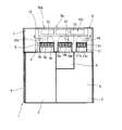
- the closed switchboard 1 As shown in FIGS. 1 and 2, the closed switchboard 1 according to the embodiment of the present invention has a housing 2 made of grounded metal, and the inside of the housing 2 is divided into a plurality of compartments (circuit breaker chamber 3 and busbars It is divided into a room 4 and a cable room 5).
- the actual closed type switchboard 1 other closed type switchboards and covers are provided on the side of the closed type switchboard 1, and the inside of the arc gas distributed pressure relief chamber 8 can not be seen, but for convenience of explanation, In the closed switchboard 1 shown in FIG. 1, other closed switchboards or covers are not shown.
- the circuit breaker chamber 3 (VCB chamber) is disposed on the front side (that is, the left side of FIG. 2) of the closed switchboard 1, and a lead-out type breaker (in the circuit breaker chamber 3) Not shown) is accommodated.
- a breaker chamber opening is formed on the front side of the breaker chamber 3, and a door 6 is provided at the breaker chamber opening.
- a relay box 7 in which the control device is accommodated is disposed above the circuit breaker chamber 3.
- a bus room 4 in which a three-phase bus (not shown) is disposed is disposed.
- the bus bar is connected to the main circuit terminal of the disconnecting part connected to one end of the circuit breaker.
- a cable chamber 5 in which a load-side cable (not shown) is accommodated is disposed on the lower rear side of the circuit breaker room 3 and on the rear side of the bus room 4.
- the cable is connected to the main circuit terminal of the disconnecting part connected to the other end of the circuit breaker.
- An arc gas dispersion pressure release relaxation chamber 8 is disposed above the circuit breaker chamber 3, the bus room 4 and the cable chamber 5. Exhaust ducts 9, 10 and 11 communicating with the arc gas dispersed pressure release relaxation chamber 8 are provided on the ceilings of the circuit breaker chamber 3, bus room 4 and cable chamber 5, respectively, and the upper ends of the exhaust ducts 9, 10 and 11 are provided. , Flappers 12, 13 and 14 are provided. Further, a pressure relaxation shield tank 15 is provided at an arc gas dispersion pressure release relaxation chamber opening 8 a formed in the upper part of the arc gas dispersion pressure release relaxation chamber 8.
- the exhaust ducts 9, 10 and 11 are extended from the circuit breaker chamber 3, the bus chamber 4 and the cable chamber 5 in the direction of the arc gas dispersed pressure release chamber 8 respectively.
- the volumes of the circuit breaker room 3, the bus room 4 and the cable room 5 are expanded. That is, by providing the exhaust ducts 9, 10 and 11, the volumes of the circuit breaker chamber 3, the bus room 4 and the cable chamber 5 are respectively enclosed by thick lines in the figure (the compartments 3, 4 and 5). And the volume of the exhaust ducts 9, 10, 11). If the volume of the circuit breaker room 3, the bus room 4 and the cable room 5 increases, the degree of increase in internal pressure when an internal arc accident etc. occurs inside the circuit breaker room 3, the bus room 4 and the cable room 5 It will be reduced.
- FIG. 3 is an enlarged view of the exhaust duct 9 provided in the circuit breaker chamber 3
- the structures of the exhaust ducts 10 and 11 provided in the bus room 4 and the cable chamber 5 are also the structure of the exhaust duct 9 and As they are the same, the corresponding symbols are described in parentheses.
- exhaust duct upper openings 9a, 10a, 11a are formed at the upper ends of the exhaust ducts 9, 10, 11, exhaust duct upper openings 9a, 10a, 11a are formed. Further, exhaust duct side openings 9b, 10b, 11b are formed on the side portions of the exhaust ducts 9, 10, 11 for communicating between the respective exhaust ducts 9, 10, 11 and the arc gas dispersion pressure release relaxation chamber 8.
- the mesh duct members 9c, 10c and 11c are provided on the exhaust duct side surface openings 9b, 10b and 11b. Assuming that the mesh members 9c, 10c and 11c are, for example, stainless steel 20 mesh (20 meshes per inch), ventilation between the respective exhaust ducts 9, 10 and 11 and the arc gas dispersion pressure release relaxation chamber 8 is ensured. And foreign matter is suppressed from entering the exhaust ducts 9, 10, 11 from the outside.
- the flappers 12, 13, 14 are provided to be able to open and close the exhaust duct upper openings 9a, 10a, 11a.
- the end of one side of the flapper 12, 13, 14 is supported, for example, by the upper end of the exhaust duct 9, 10, 11 via a hinge or the like. Further, the end of the other side of the flapper 12, 13, 14 is fixed to the upper end of the exhaust duct 9, 10, 11 by a fixing member (not shown) such as a screw. Then, when the internal pressure of the circuit breaker room 3, the bus room 4 or the cable room 5 rises and the pressure exceeds a certain value, the fixing member is opened and the flappers 12, 13 and 14 are opened.
- Ventilation parts 12a, 13a, 14a are formed on the main surfaces of the flappers 12, 13, 14 for communicating between the exhaust ducts 9, 10, 11 and the arc gas dispersion pressure release relaxation chamber 8, and the ventilation parts 12a, Reticulated members 12b, 13b and 14b are provided on 13a and 14a.
- the mesh members 12b, 13b and 14b for example, stainless steel 20 mesh, ventilation between the exhaust ducts 9, 10 and 11 and the arc gas dispersion pressure release relaxation chamber 8 is ensured, and foreign substances are exhaust ducts from the outside Entry into 9, 10, 11 is suppressed.
- the pressure relaxation shield tank 15 has the same area as the shield tank opening 15a connected to the arc gas dispersion pressure release relaxation chamber opening 8a and the arc gas dispersion pressure release chamber opening 8a. It is a bottomed tank with an open top having a bottom plate 15 b (shield plate).
- a shielding tank side opening 15c is formed on the side of the pressure relaxation shielding tank 15, and the arc gas (hereinafter referred to as a heat gas) generated in the circuit breaker chamber 3 (or the bus chamber 4 or the cable chamber 5) After being depressurized in the arc gas dispersed pressure release relaxation chamber 8, it is discharged to the outside of the closed type switchboard 1 through the shielding tank side opening 15c.
- the bottom plate 15b of the pressure relaxation shield tank 15 is provided in the vicinity of the exhaust duct upper opening 9a, 10a, 11a and separated from the exhaust duct upper opening 9a, 10a, 11a.
- the width and depth (that is, the area of the bottom plate 15b) of the bottom plate 15b is larger than the widths and depths of the exhaust duct upper openings 9a, 10a and 11a (that is, the opening areas of the exhaust duct upper openings 9a, 10a and 11a)
- the high temperature decomposition products discharged through the exhaust ducts 9, 10, 11 all come in contact with the bottom plate 15b. As shown in FIG.
- the separation distance L between the upper end of the exhaust ducts 9, 10 and 11 and the bottom plate 15b is determined by the high temperature decomposition products released from the circuit breaker chamber 3 (or the busbar chamber 4 and the cable chamber 5). It is set so as to be all within the distance of hitting the bottom plate 15b and more than the distance to which the high temperature decomposition products are dissipated.
- the separation distance L is a length (protrusion length) of an end portion of the bottom plate 15b that protrudes in the width direction (or depth direction) from the side end of the exhaust duct upper opening 9a, 10a, 11a provided opposite to the bottom plate 15b.
- the length X) and the extension length H of the exhaust ducts 9, 10, 11 in the direction of the arc gas dispersion pressure release relaxation chamber 8 can be determined. For example, when the separation distance L from the upper end of the exhaust ducts 9, 10, 11 to the bottom plate 15b is "1", the protrusion length X of the width and depth of the bottom plate 15b is "0.2 to 0.3".
- a pressure relaxation shield tank 15 is provided in the arc gas dispersion pressure release relaxation chamber 8 so that the extension length H of the ducts 9, 10, 11 has a dimensional ratio of “1 to 2”. Further, the pressure relief shield tank 15 may be provided at a distance at which the flappers 12, 13, 14 contact the bottom plate 15b when the flappers 12, 13, 14 are opened.
- the fixing member of the flapper 12 is released and the flapper 12 is opened.
- the heat gas inside the circuit breaker chamber 3 is released from the exhaust duct 9, the pressure inside the circuit breaker chamber 3 is reduced, and the heat gas expands and diffuses in the arc gas dispersed pressure release relaxation chamber 8. , The temperature and pressure of the hot gas are reduced.
- the volume of the arc gas dispersed pressure release relaxation chamber 8 is larger, the effect of expansion and diffusion of the heat gas is enhanced, and the temperature and pressure of the heat gas are reduced.
- the heat gas passes through the shielding tank side opening 15c, moves into the pressure relieving shielding tank 15, and is released to the outside of the closed switchboard 1 from the arc gas dispersed pressure releasing relaxation room opening 8a.
- the shielding tank side surface opening 15c in at least one set of opposing side portions of the pressure relaxation shielding tank 15, the heat gas flowing into the pressure relaxation shielding tank 15 from each shielding tank side opening 15c. The direction of is reversed. As a result, the heat gases flowing from the shielding tank side openings 15 c collide with each other, and the force of the heat gas is reduced.
- the flow of the heat gas is directed toward the center of the pressure relief shield tank 15 by forming the shield tank side surface openings 15 c on the opposing side portions, respectively.
- the momentum of the heat gas is more relaxed.
- the ratio of the high temperature decomposition products discharged from the openings 9a, 10a, 11a to the bottom plate 15b as the bottom plate 15b of the pressure relaxation shield tank 15 is provided closer to the openings 9a, 10a, 11a of the compartments 3, 4, 5 Will increase.
- the bottom plate 15b is provided so as to be located on the extension of the maximum release angle (the maximum opening angle with respect to the release direction) of the high temperature decomposition products released from the exhaust ducts 9, 10, 11 , 11 hit the bottom plate 15b, and thereafter are released from the arc gas dispersed pressure release relaxation chamber opening 8a (or accumulated in the arc gas dispersed pressure released relaxation chamber 8).
- the arc gas dispersed pressure release relaxation chamber opening 8a or accumulated in the arc gas dispersed pressure released relaxation chamber 8
- the volume of the arc gas dispersed pressure releasing chamber 8 for expanding and diffusing the hot gas is secured large, and the bottom plate of the pressure relaxing shield tank 15
- 15b shield plate
- the openings ie, the exhaust duct upper openings 9a, 10a, 11a
- the closed type switchboard 1 which concerns on embodiment of this invention, by providing the pressure relaxation shielding tank 15, heat gas will bypass the pressure relaxation shielding tank 15, and will be distribute
- the different directions of the heat gases flowing in from the opposite sides of the pressure relief shield tank 15 collide with each other in the pressure relief shield tank 15 to further reduce the momentum of the heat gas.
- the kinetic energy of the high temperature decomposition product is reduced, and the kinetic energy of the high temperature decomposition product released to the outside of the closed switchboard 1 and the amount of the high temperature decomposition product released can be reduced.
- the structure of the heat gas discharge path in which the direction of the heat gas is directed toward the center of the pressure relief shield tank 15 allows the heat gas and high temperature decomposition toward the outside of the closed switch board 1 (that is, the indicator direction). The amount of products can be reduced, and the safety of the closed switchboard 1 is improved.
- the total area of the shielding tank side opening 15 c is made larger than the area between the peripheral edge of the bottom plate 15 b of the pressure relieving shielding tank 15 and the inner peripheral surface of the arc gas dispersed pressure release relieving chamber 8, and the pressure relieving shielding tank 15
- the discharge path advances The cross-sectional area of the discharge path becomes large, and the pressure increase inside the arc gas dispersion pressure release relaxation chamber 8 can be suppressed.
- the closed type switchboard 1 by providing mesh members 12b, 13b and 14b in the flappers 12, 13 and 14, the peak pressure of the internal pressure of the compartments 3, 4 and 5 can be obtained. It can be suppressed. That is, since the heat gas in the compartments 3, 4 and 5 is discharged through the reticulated members 12b, 13b and 14b according to the pressure rise in the compartments 3, 4 and 5, the plate-like shape as in the prior art In comparison with the case of using the flapper, the heat gas inside the compartments 3, 4 and 5 is not discharged at once simultaneously with the opening of the flapper, and the pressure peaks in the compartments 3, 4 and 5 are reduced. Can.
- the internal pressure peak By reducing the internal pressure peak, it is possible to reduce the momentum of the hot gases and high temperature decomposition products released from the compartments 3, 4 and 5. Further, by reducing the internal pressure peak, the pressure resistance (strength) required for the closed type switchboard 1 can be lowered, and the closed type switchboard 1 can be manufactured inexpensively.
- the reticulated members 12b, 13b, 14b are dissolved by the heat gas and the high temperature decomposition products passing through the reticulated members 12b, 13b, 14b, thereby reducing the thermal energy and kinetic energy of the heat gas and the high temperature decomposition products. be able to.
- the heat gas discharged from the openings of the compartments 3, 4 and 5 impinges on the plate surfaces of the flappers 12, 13 and 14 so that a certain direction is achieved.
- heat is applied to the flappers 12, 13 and 14 by forming the vents 12a, 13a and 14a of stainless steel 20 mesh.
- the gas is divided into a flow passing through the vents 12 a, 13 a and 14 a of the flappers 12, 13 and 14 and a flow rebounding to the flappers 12, 13 and 14. That is, it is possible to reduce the bias of the flow of the heat gas in the arc gas dispersed pressure release relaxation chamber 8.
- the closed type switchboard 1 providing the exhaust ducts 9, 10, 11 in the compartments 3, 4, 5 increases the volume of the compartments 3, 4, 5
- the pressure rise at the occurrence of the internal arc accident can be reduced.
- the volume of the exhaust ducts 9, 10, 11 relative to the compartments 3, 4, 5 to about 10% to 30%, the effect of suppressing the pressure increase inside the compartments 3, 4, 5 is obtained.
- the mesh members 9c, 10c, 11c are provided on the side portions of the exhaust ducts 9, 10, 11, the air in the compartments 3, 4, 5 in response to the pressure increase in the compartments 3, 4, 5
- the gas passes through the mesh members 9c, 10c and 11c and is discharged into the arc gas dispersive pressure relief chamber 8.
- the heat gas is discharged in the horizontal direction of the exhaust ducts 9, 10, 11 through the reticulated members 9c, 10c, 11c provided on the side portions of the exhaust ducts 9, 10, 11 as well.
- the directions of release are dispersed to reduce the momentum of the heat gas, and the diffusion of the heat gas is promoted.
- the closed type switchboard of the present invention was explained in detail by showing a specific example, the closed type switchboard of the present invention is not limited to the above-mentioned embodiment, and it is appropriate to Design changes are possible.
- each configuration such as a pressure relief shield tank, a reticulated member provided on a flapper, and an exhaust duct, individually exerts remarkable effects. Therefore, the effects of the closed type switchboard of the present invention can be partially obtained even in the form of individually providing the elements having special effects.
- the openings (and flappers) of the individual compartments are Each may be provided with a pressure relief shield tank. That is, the effect of the closed switchboard of the present invention can be obtained by providing the pressure relief shield tank at least at the opening (and flapper) of one compartment.
Landscapes
- Engineering & Computer Science (AREA)
- Power Engineering (AREA)
- Patch Boards (AREA)
- Gas-Insulated Switchgears (AREA)
Abstract
筐体(2)内を複数の区画室(遮断器室(3)、母線室(4)、ケーブル室(5))に区画した閉鎖形配電盤(1)である。遮断器室(3)、母線室(4)及びケーブル室(5)の上方に、アークガス分散放圧緩和室(8)を配置し、遮断器室(3)、母線室(4)及びケーブル室(5)の天井部に、それぞれアークガス分散放圧緩和室(8)と連通する排気ダクト(9,10,11)を設ける。排気ダクト(9,10,11)の上端部に、フラッパ(12,13,14)を設け、アークガス分散放圧緩和室(8)の上部に形成された開口部(8a)に、圧力緩和遮蔽槽(15)を設ける。フラッパ(12,13,14)の主面に、各排気ダクト(9,10,11)とアークガス分散放圧緩和室(8)との間を連通する通気部(12a,13a,14a)を形成し、この通気部(12a,13a,14a)に網状部材(12b,13b,14b)を設ける。
Description
本発明は、筐体内に母線の遮断を行う主回路部品等を収納する閉鎖形配電盤に関し、詳しくは内部短絡事故等の発生時における放圧構造に関するものである。
閉鎖形配電盤は、接地された金属箱内を、いくつかの区画室(コンパートメント)に仕切り、各区画室に遮断器や、母線、接続導体等の主回路部品を収納した構造を有する。
各区画室内で、短絡事故等によるアークの発生を伴う内部アーク事故が発生すると、区画室の内部圧力が過大に上昇し、筐体、扉、監視窓等からアークガスが噴出するおそれがある。そこで、例えば、スイッチギア等の閉鎖形配電盤では、各区画室に放圧フラッパを設け、内部アーク事故発生時の過大な圧力上昇を抑制している(例えば、特許文献1-5)。
また、区画室室内で内部アーク事故が発生すると、区画室に収納された部品は、ガス化、蒸気化した高温分解生成物を発生し、放圧フラッパを介して区画室の外へ排出される。そこで、図4に示すように、従来技術に係る閉鎖形配電盤16では、背面カバー17等の仕切りを設けて、区画室の外へ排出された高温分解生成物の周囲への飛散を防止している。
このように、閉鎖形配電盤では、内部アーク事故発生時の区画室の圧力上昇の抑制及び放出されるガス化,蒸気化した高温分解生成物の放出方向を制限することで、内部アーク事故発生時の安全性を確保している。
閉鎖形配電盤の安全性は、内部アーク短絡試験(例えば、IEC 62271-200)等により検証されることとなる。具体的に説明すると、例えば、IEC 62271-200の内部アーク短絡試験(試験項目6.106 内部事故アーク試験)では、閉鎖形配電盤の前後・左または右・水平面(床面から高さ2mの位置)に、インジケータ(150cm角の黒い綿布)を設置した状態で、閉鎖形配電盤内で一定時間内部閃絡させ、インジケータが着火しないことや、扉やカバーが開放しないこと等の基準を満たしているか否かの判定が行われる。
しかしながら、区画室から外部に放出された高温分解生成物が、天井等から跳ね返りインジケータに当たると、インジケータが焼損してしまい、前記の内部アーク短絡試験の判定が不可となるおそれがある。
そこで、区画室から外部に放出される高温分解生成物の勢いを低減するために、放出ガス圧力を低減することが考えられる。しかし、放出ガス圧力を低減するために、放圧フラッパからのガス放出量を抑制すると、区画室内の圧力が上昇して、筐体、扉、監視窓等からガスが噴出するおそれがある。
上記事情に鑑み、本発明は、閉鎖形配電盤の放出ガス圧力及び高温分解生成物の放出量の低減に貢献する技術を提供することを目的とする。
上記目的を達成する本発明の閉鎖形配電盤の一態様は、筐体内を区画することで形成され、主回路部品が収納される区画室(コンパートメント)と、区画室に形成された開口部を介して区画室と連通するアークガス分散放圧緩和室と、区画室の開口部に設けられ、区画室の圧力変化に応じて開放される放圧フラッパと、を有する閉鎖形配電盤であって、放圧フラッパに、区画室とアークガス分散放圧緩和室とを連通する通気部を設け、さらに、アークガス分散放圧緩和室内であって、区画室開口部から離間して、この区画室の開口部の幅および奥行きより大きい遮蔽板を設ける。
また、上記目的を達成する本発明の閉鎖形配電盤の他の態様は、上記閉鎖形配電盤において、区画室とアークガス分散放圧緩和室との間を連通する排気ダクトを、区画室からアークガス分散放圧緩和室内に延設する。
本発明の閉鎖形配電盤について、図面を参照して詳細に説明する。なお、実施形態の説明では、閉鎖形配電盤内を遮断器室、母線室及びケーブル室の3つの区画室で区切った形態を例示して説明するが、閉鎖形配電盤内の構成は実施形態に限定されるものではなく、本発明は、適宜必要な回路部品を収納可能な数だけ区画室を設けた閉鎖形配電盤に適用することができる。
図1乃至3を参照して、閉鎖形配電盤1の内部構成について説明する。図1,2に示すように、本発明の実施形態に係る閉鎖形配電盤1は、接地金属製の筐体2を有し、筐体2内は、複数の区画室(遮断器室3、母線室4、ケーブル室5)に区画される。なお、実際の閉鎖形配電盤1では、閉鎖形配電盤1の側部には他の閉鎖形配電盤やカバーが設けられ、アークガス分散放圧緩和室8内を見ることはできないが、説明の都合上、図1に示す閉鎖形配電盤1では、他の閉鎖形配電盤またはカバーを図示省略している。
図2に示すように、閉鎖形配電盤1の前面側(すなわち、図2の左側)には、遮断器室3(VCB室)が配置され、遮断器室3内には引出形の遮断器(図示せず)が収容される。遮断器室3の前面側には遮断器室開口部が形成されており、この遮断器室開口部には扉6が設けられる。また、遮断器室3の上方には、制御機器が収納されるリレーボックス7が配置される。
遮断器室3の背面側上方には、例えば、三相の母線(図示せず)が配設される母線室4が配置される。母線は、遮断器の一端側に接続された断路部の主回路端子と接続される。
遮断器室3の背面側下方及び母線室4の背面側には、負荷側のケーブル(図示せず)が収容されるケーブル室5が配置される。ケーブルは、遮断器の他端側に接続された断路部の主回路端子と接続される。
遮断器室3、母線室4及びケーブル室5の上方には、アークガス分散放圧緩和室8が配置される。遮断器室3、母線室4及びケーブル室5の天井部には、それぞれアークガス分散放圧緩和室8と連通する排気ダクト9,10,11が設けられ、排気ダクト9,10,11の上端部には、フラッパ12,13,14が設けられる。また、アークガス分散放圧緩和室8の上部に形成されたアークガス分散放圧緩和室開口部8aには、圧力緩和遮蔽槽15が設けられる。
排気ダクト9,10,11は、遮断器室3、母線室4、ケーブル室5からアークガス分散放圧緩和室8方向に延設される。排気ダクト9,10,11を設けることで、遮断器室3、母線室4、ケーブル室5の容積が拡大する。すなわち、排気ダクト9,10,11を設けることで、各遮断器室3、母線室4、及びケーブル室5の容積は、それぞれ図中太線で囲われた領域(各区画室3,4,5の容積と排気ダクト9,10,11の容積の和)となる。遮断器室3,母線室4及びケーブル室5の容積が増えることで、遮断器室3、母線室4、ケーブル室5内部で内部アーク事故等が発生した場合に、内部圧力が上昇する度合いが低減されることとなる。
図3を参照して、排気ダクト9,10,11部分について、より詳細に説明する。なお、図3は、遮断器室3に設けられた排気ダクト9の拡大図であるが、母線室4及びケーブル室5に設けられた排気ダクト10,11の構造も、排気ダクト9の構造と同じであるので、対応する符合を括弧内に記載している。
排気ダクト9,10,11の上端には、排気ダクト上部開口部9a,10a,11aが形成される。また、排気ダクト9,10,11の側部には、各排気ダクト9,10,11とアークガス分散放圧緩和室8との間を連通する排気ダクト側面開口部9b,10b,11bが形成され、排気ダクト側面開口部9b,10b,11bには網状部材9c,10c,11cが設けられる。網状部材9c,10c,11cを、例えば、ステンレス20メッシュ(1インチあたりの網目が20個)とすると、各排気ダクト9,10,11とアークガス分散放圧緩和室8との間の通気が確保され、且つ異物が外部から排気ダクト9,10,11内に入ることが抑制される。
フラッパ12,13,14は、各排気ダクト上部開口部9a,10a,11aを開閉可能に設けられる。フラッパ12,13,14の一側辺の端部は、例えば、排気ダクト9,10,11の上端部にヒンジ等を介して支持される。また、フラッパ12,13,14の他側辺の端部は、排気ダクト9,10,11の上端部にビス等の固定部材(図示省略)により固定される。そして、遮断器室3、母線室4またはケーブル室5の内部圧力が上昇して、その圧力が一定値を超えると、固定部材が開放され、フラッパ12,13,14が開くこととなる。
フラッパ12,13,14の主面には、排気ダクト9,10,11とアークガス分散放圧緩和室8との間を連通する通気部12a,13a,14aが形成されており、通気部12a,13a,14aには網状部材12b,13b,14bが設けられる。網状部材12b,13b,14bを、例えば、ステンレス20メッシュとすることで、排気ダクト9,10,11とアークガス分散放圧緩和室8との間の通気が確保され、且つ異物が外部から排気ダクト9,10,11内に入ることが抑制される。
圧力緩和遮蔽槽15は、例えば、図1に示すように、アークガス分散放圧緩和室開口部8aと接続される遮蔽槽開口部15aと、アークガス分散放圧緩和室開口部8aと同じ面積を有する底板15b(遮蔽板)と、を有する上部が開口した有底の槽である。圧力緩和遮蔽槽15の側部には遮蔽槽側面開口部15cが形成されており、遮断器室3(若しくは、母線室4やケーブル室5)で発生したアークガス(以後、熱ガスと称する)が、アークガス分散放圧緩和室8で減圧された後、遮蔽槽側面開口部15cを通って閉鎖形配電盤1の外部に放出される。なお、圧力緩和遮蔽槽15の底板15bは、排気ダクト上部開口部9a,10a,11aの近傍であって、排気ダクト上部開口部9a,10a,11aから離間して設けられる。この底板15bの幅と奥行き(すなわち、底板15bの面積)は排気ダクト上部開口部9a,10a,11aの幅と奥行き(すなわち、排気ダクト上部開口部9a,10a,11aの開口面積)よりも大きく、排気ダクト9,10,11を通って放出される高温分解生成物がすべて底板15bに当たる構造となっている。図2に示すように、排気ダクト9,10,11の上端と底板15bとの離間距離Lは、遮断器室3(若しくは、母線室4やケーブル室5)から放出される高温分解生成物がすべて底板15bに当たる距離以内で、且つ高温分解生成物が放熱される距離以上となるように設定される。この離間距離Lは、底板15bと対向して設けられる排気ダクト上部開口部9a,10a,11aの側端から幅方向(若しくは、奥行方向)に突き出した底板15bの端部の長さ(突き出し長さX)、及び排気ダクト9,10,11のアークガス分散放圧緩和室8方向への延設長さHで定めることができる。例えば、排気ダクト9,10,11の上端から底板15bまでの離間距離Lを「1」とした場合、底板15bの幅と奥行きの突き出し長さXが「0.2~0.3」、排気ダクト9,10,11の延設長さHが「1~2」の寸法比となるように、圧力緩和遮蔽槽15がアークガス分散放圧緩和室8内に設けられる。また、フラッパ12,13,14が開放したときに、フラッパ12,13,14が底板15bに当接する距離に圧力緩和遮蔽槽15を設けてもよい。
次に、内部短絡アーク試験によって、遮断器室3内部で、内部アーク事故(閉鎖形配電盤1の遮断器室3内部での相間短絡または地絡によるアーク事故)を発生させたときのフラッパ12の動作や圧力緩和遮蔽槽15、排気ダクト9及びアークガス分散放圧緩和室8等の効果について説明する。なお、他の区画室(母線室4やケーブル室5)で内部アーク事故が発生した場合のフラッパ13,14の動作及び圧力緩和遮蔽槽15及び排気ダクト10,11等の効果も、遮断器室3内部で内部アーク事故が発生した場合と同じであるため、詳細な説明は省略する。
遮断器室3内部で、内部アーク事故が発生すると、アークにより遮断器室3内部の空気が膨張するとともに、高温のアークにより遮断器室3内部の部品やブッシングが溶けて金属粉等の高温分解生成物が生じる。
遮断器室3内部の空気の膨張により遮断器室3内部の圧力が上昇すると、この膨張した空気は、フラッパ12に設けられた網状部材12b及び排気ダクト9の網状部材9cを通って、アークガス分散放圧緩和室8内に放出される。このとき、フラッパ12の網状部材12bを通過して放出された高温分解生成物の大部分は、排気ダクト上部開口部9aの幅と奥行きよりも大きい圧力緩和遮蔽槽15の底板15bに当たることで、アークガス分散放圧緩和室8に放出された時の勢いを失うため、高温分解生成物が閉鎖形配電盤1の外部に放出されることがほとんどない。この時、底板15bまでの離間距離L、突き出し長さX及び延設長さHを前述の寸法比とすることで、熱ガスがすべて底板15bに当たり、且つ高温分解生成物が放熱され、好適となる。
さらに、遮断器室3内部の圧力が上昇すると、フラッパ12の固定部材が解放されてフラッパ12が開放する。その結果、排気ダクト9から遮断器室3内部の熱ガスが放出され、遮断器室3内部の圧力が低減されるとともに、熱ガスがアークガス分散放圧緩和室8内で膨張及び拡散することで、熱ガスの温度や圧力が低減される。この場合、アークガス分散放圧緩和室8の容積が大きいほどに熱ガスの膨張及び拡散の効果が高まることになり、熱ガスの温度や圧力が低減される。
熱ガスは、遮蔽槽側面開口部15cを通過して圧力緩和遮蔽槽15内に移動し、アークガス分散放圧緩和室開口部8aから閉鎖形配電盤1の外部に放出される。このとき、圧力緩和遮蔽槽15の少なくとも対向する1組以上の側部に遮蔽槽側面開口部15cを形成することで、各遮蔽槽側面開口部15cから圧力緩和遮蔽槽15内に流入する熱ガスの向きが逆となる。その結果、各遮蔽槽側面開口部15cから流入した熱ガス同士がぶつかりあい、熱ガスの勢いが低減される。なお、圧力緩和遮蔽槽15が直方体形状の場合には、対向する側部それぞれに遮蔽槽側面開口部15cを形成することで、熱ガスの流れが圧力緩和遮蔽槽15の中心に向かう流れとなり、熱ガスの勢いがより緩和される。
圧力緩和遮蔽槽15の底板15bは、区画室3,4,5の開口部9a,10a,11a近くに設けるほど、開口部9a,10a,11aから放出される高温分解生成物が底板15bに当たる割合が増加する。例えば、底板15bは、排気ダクト9,10,11から放出される高温分解生成物の最大放出角度(放出方向に対する最大開き角)の延長上に位置するように設けることで、排気ダクト9,10,11から放出された高温分解生成物のほとんどが底板15bに当たり、その後にアークガス分散放圧緩和室開口部8aから放出(若しくは、アークガス分散放圧緩和室8内に蓄積)されることとなる。その結果、閉鎖形配電盤1から放出される高温分解生成物の勢い及び放出量を低減することができる。
以上のような、本発明の実施形態に係る閉鎖形配電盤1によれば、熱ガスの膨張及び拡散を行うアークガス分散放圧緩和室8の容積を大きく確保し、且つ圧力緩和遮蔽槽15の底板15b(遮蔽板)を遮断器室3、母線室4、ケーブル室5等の区画室に形成された開口部(すなわち、排気ダクト上部開口部9a,10a,11a)近傍に設けることで、区画室3,4,5で生成した高温分解生成物が直接閉鎖形配電盤1の外部に放出されることを抑制することができる。
また、本発明の実施形態に係る閉鎖形配電盤1によれば、圧力緩和遮蔽槽15を設けることで、熱ガスが圧力緩和遮蔽槽15を迂回して流通することとなり、熱ガスのエネルギー(温度及び圧力)がより低減される。また、圧力緩和遮蔽槽15の対向する側部から流入する異なる向きの熱ガス同士が圧力緩和遮蔽槽15内でぶつかることで、熱ガスの勢いがより低減される。その結果、高温分解生成物の運動エネルギーが減少し、閉鎖形配電盤1の外部に放出される高温分解生成物の運動エネルギー及び高温分解生成物の放出量を低減することができる。また、熱ガスの向きが圧力緩和遮蔽槽15の中心へ向かう向きとなる熱ガスの放出経路の構造とすることで、閉鎖形配電盤1の外部(すなわち、インジケータ方向)へ向かう熱ガス及び高温分解生成物の量を低減することができ、閉鎖形配電盤1の安全性が向上する。なお、遮蔽槽側面開口部15cの総面積を、圧力緩和遮蔽槽15の底板15bの周縁とアークガス分散放圧緩和室8内周面との間の面積より大きくし、且つ、圧力緩和遮蔽槽15の底板15bの周縁とアークガス分散放圧緩和室8内周面との間の面積を、個々の排気ダクト上部開口部9a,10a,11aの面積より大きくすることで、放出経路が進むに連れて放出経路の断面積が大きくなり、アークガス分散放圧緩和室8内部の圧力上昇を抑制することができる。
また、圧力緩和遮蔽槽15を、フラッパ12,13,14の近傍に設けることで、フラッパ12,13,14に網状部材12b,13b,14bを設けた場合にも、外部から水や異物等が区画室3,4,5内部に侵入することを効果的に防止することができる。
また、本発明の実施形態に係る閉鎖形配電盤1によれば、フラッパ12,13,14に網状部材12b,13b,14bを設けることで、区画室3,4,5の内部圧力のピーク圧力を抑制することができる。すなわち、区画室3,4,5内部の圧力上昇にしたがって、区画室3,4,5内部の熱ガスが網状部材12b,13b,14bを通過して放出されるので、従来のような板状のフラッパを用いた場合と比較して、区画室3,4,5内部の熱ガスがフラッパの開放と同時に一気に放出されることがなく、区画室3,4,5内部圧力ピークを低減することができる。内部圧力ピークを低減することで、区画室3,4,5から放出される熱ガス及び高温分解生成物等の勢いを低減できる。また、内部圧力ピークを低減することで、閉鎖形配電盤1に求められる耐圧性(強度)を低くすることができ、閉鎖形配電盤1を安価に製造することができる。
また、網状部材12b,13b,14bを通過した熱ガス及び高温分解生成物により、網状部材12b,13b,14bが溶解することで、熱ガス及び高温分解生成物の熱エネルギー及び運動エネルギーを低減することができる。
また、従来のような板状のフラッパが半開状態の場合、区画室3,4,5の開口部から放出される熱ガスは、フラッパ12,13,14の板面に当たることで、一定の方向のみに放出されることとなるが、本発明のフラッパ12,13,14の場合にはステンレス20メッシュによる通気部12a,13a,14aを形成することで、フラッパ12,13,14に当たった熱ガスは、フラッパ12,13,14の通気部12a,13a,14aを通過する流れと、フラッパ12,13,14に跳ね返る流れとに分かれることとなる。つまり、アークガス分散放圧緩和室8内における熱ガスの流れの偏りを低減することができる。
また、本発明の実施形態に係る閉鎖形配電盤1によれば、区画室3,4,5に排気ダクト9,10,11を設けることで、区画室3,4,5の容積が増大することとなり、区画室3,4,5で、内部アーク事故発生時の圧力上昇を低減することができる。例えば、区画室3,4,5に対する排気ダクト9,10,11の容積を、10%~30%程度とすることで、区画室3,4,5内部の圧力上昇を抑制する効果を得ることができる。さらに、排気ダクト9,10,11の側部に網状部材9c,10c,11cを設けることで、区画室3,4,5内部における圧力上昇に応じて、区画室3,4,5内部の空気が網状部材9c,10c,11cを通過してアークガス分散放圧緩和室8内に放出される。その結果、区画室3,4,5の開口部9a,10a,11aから放出される熱ガスのピーク圧力を低減することができる。また、排気ダクト9,10,11の側部に設けられる網状部材9c,10c,11cを通過して、熱ガスが排気ダクト9,10,11の水平方向にも放出されるので、熱ガスの放出方向が分散されて熱ガスの勢いが低減されるとともに、熱ガスの拡散が促進される。
以上、本発明の閉鎖形配電盤について具体例を示して詳細に説明したが、本発明の閉鎖形配電盤は、上述した実施形態に限定されるものではなく、本発明の特徴を損なわない範囲で適宜設計変更が可能である。
例えば、本発明の閉鎖形配電盤は、圧力緩和遮蔽槽、フラッパに設けられる網状部材、及び排気ダクト等、各々の構成が個別に格別な効果を奏するものである。したがって、格別な効果を奏する各要素を個別に設ける形態であっても、本発明の閉鎖形配電盤の効果を部分的に得ることができる。
また、実施形態の説明では、すべての区画室の開口部(及びフラッパ)に対して一つの圧力緩和遮蔽槽を設ける形態を例示しているが、個々の区画室の開口部(及びフラッパ)にそれぞれ圧力緩和遮蔽槽を設ける形態であってもよい。つまり、圧力緩和遮蔽槽は、少なくとも、一つの区画室の開口部(及びフラッパ)に設けることで、本発明の閉鎖形配電盤の効果を得ることができる。
Claims (9)
- 筐体内を区画することで形成され、主回路部品が収納される区画室と、
前記区画室に形成された開口部を介して当該区画室と連通するアークガス分散放圧緩和室と、
前記区画室の開口部に設けられ、該区画室の圧力変化に応じて開放される放圧フラッパと、を有する閉鎖形配電盤であって、
前記放圧フラッパに、前記区画室と前記アークガス分散放圧緩和室とを連通する通気部を設け、
前記アークガス分散放圧緩和室内であって、前記区画室の開口部から離間して、この区画室の開口部の幅および奥行きより大きい遮蔽板を設ける閉鎖形配電盤。 - 前記アークガス分散放圧緩和室に形成された開口部に接続される開口を有し、前記遮蔽板を底板とする圧力緩和遮蔽槽を、前記アークガス分散放圧緩和室内に設ける請求項1に記載の閉鎖形配電盤。
- 前記放圧フラッパの通気部に網状部材を設ける請求項1または請求項2に記載の閉鎖形配電盤。
- 前記区画室と前記アークガス分散放圧緩和室との間を連通する排気ダクトを、前記区画室から前記アークガス分散放圧緩和室内に延設し、
該排気ダクトの上端部に前記放圧フラッパを設ける請求項1から請求項3のいずれか1項に記載の閉鎖形配電盤。 - 前記排気ダクトの側部に、当該排気ダクトと前記アークガス分散放圧緩和室との間を連通する側面開口部を形成し、該側面開口部に網状部材を設ける請求項4に記載の閉鎖形配電盤。
- 前記圧力緩和遮蔽槽の少なくとも対向する一対の側部に開口部を形成する請求項2に記載の閉鎖形配電盤。
- 前記圧力緩和遮蔽槽の側部に形成された開口部面積は、前記アークガス分散放圧緩和室の内壁面と前記遮蔽板の周縁との間に形成される隙間面積よりも大きく、
該隙間面積は、前記区画室の開口部面積よりも大きい請求項6に記載の閉鎖形配電盤。 - 前記放圧フラッパが開放したとき、該放圧フラッパが当接する距離に、前記遮蔽板を設ける請求項1から請求項7のいずれか1項に記載の閉鎖形配電盤。
- 前記排気ダクトの上端から前記遮蔽板までの離間距離をL、前記遮蔽板と対向する排気ダクトの開口端部から該排気ダクト幅方向若しくは奥行き方向に突き出した該遮蔽板の側端部の突き出し距離をX、前記排気ダクトの延設長さをH、としたとき、
L:X=1:0.2~1:0.3
L:H=1:1~1:2
の関係式を満たす請求項4から請求項8のいずれか1項に記載の閉鎖形配電盤。
Priority Applications (3)
| Application Number | Priority Date | Filing Date | Title |
|---|---|---|---|
| CN201580010661.5A CN106030943B (zh) | 2014-02-28 | 2015-02-25 | 封闭式配电盘 |
| SG11201607049PA SG11201607049PA (en) | 2014-02-28 | 2015-02-25 | Enclosed switchboard |
| JP2015511131A JP5804223B1 (ja) | 2014-02-28 | 2015-02-25 | 閉鎖形配電盤 |
Applications Claiming Priority (2)
| Application Number | Priority Date | Filing Date | Title |
|---|---|---|---|
| JP2014-039155 | 2014-02-28 | ||
| JP2014039155 | 2014-02-28 |
Publications (1)
| Publication Number | Publication Date |
|---|---|
| WO2015129716A1 true WO2015129716A1 (ja) | 2015-09-03 |
Family
ID=54009033
Family Applications (1)
| Application Number | Title | Priority Date | Filing Date |
|---|---|---|---|
| PCT/JP2015/055315 Ceased WO2015129716A1 (ja) | 2014-02-28 | 2015-02-25 | 閉鎖形配電盤 |
Country Status (5)
| Country | Link |
|---|---|
| JP (1) | JP5804223B1 (ja) |
| CN (1) | CN106030943B (ja) |
| MY (1) | MY160983A (ja) |
| SG (1) | SG11201607049PA (ja) |
| WO (1) | WO2015129716A1 (ja) |
Cited By (1)
| Publication number | Priority date | Publication date | Assignee | Title |
|---|---|---|---|---|
| WO2018055830A1 (ja) * | 2016-09-26 | 2018-03-29 | 株式会社日立産機システム | スイッチギヤ |
Families Citing this family (4)
| Publication number | Priority date | Publication date | Assignee | Title |
|---|---|---|---|---|
| JP6439841B1 (ja) * | 2017-09-14 | 2018-12-19 | 株式会社明電舎 | 配電盤およびアークエネルギー遮断装置 |
| WO2019207666A1 (ja) * | 2018-04-25 | 2019-10-31 | 東芝三菱電機産業システム株式会社 | 電力変換装置 |
| US11631968B2 (en) | 2019-03-15 | 2023-04-18 | Ls Electric Co., Ltd. | Arc ventilation system of distributing board |
| CN110611267B (zh) * | 2019-09-16 | 2021-01-05 | 许继集团有限公司 | 一种泄压装置及使用该泄压装置的开关柜 |
Citations (3)
| Publication number | Priority date | Publication date | Assignee | Title |
|---|---|---|---|---|
| JPS6219007U (ja) * | 1985-07-17 | 1987-02-04 | ||
| JPH09275609A (ja) * | 1996-04-01 | 1997-10-21 | Mitsubishi Electric Corp | ガス封入容器の放圧ダクト |
| WO2013099393A1 (ja) * | 2011-12-27 | 2013-07-04 | 三菱電機株式会社 | 電気室 |
-
2015
- 2015-02-25 JP JP2015511131A patent/JP5804223B1/ja active Active
- 2015-02-25 SG SG11201607049PA patent/SG11201607049PA/en unknown
- 2015-02-25 WO PCT/JP2015/055315 patent/WO2015129716A1/ja not_active Ceased
- 2015-02-25 CN CN201580010661.5A patent/CN106030943B/zh active Active
- 2015-02-25 MY MYPI2016703031A patent/MY160983A/en unknown
Patent Citations (3)
| Publication number | Priority date | Publication date | Assignee | Title |
|---|---|---|---|---|
| JPS6219007U (ja) * | 1985-07-17 | 1987-02-04 | ||
| JPH09275609A (ja) * | 1996-04-01 | 1997-10-21 | Mitsubishi Electric Corp | ガス封入容器の放圧ダクト |
| WO2013099393A1 (ja) * | 2011-12-27 | 2013-07-04 | 三菱電機株式会社 | 電気室 |
Cited By (3)
| Publication number | Priority date | Publication date | Assignee | Title |
|---|---|---|---|---|
| WO2018055830A1 (ja) * | 2016-09-26 | 2018-03-29 | 株式会社日立産機システム | スイッチギヤ |
| JP2018057063A (ja) * | 2016-09-26 | 2018-04-05 | 株式会社日立産機システム | スイッチギヤ |
| EP3518358A4 (en) * | 2016-09-26 | 2020-04-29 | Hitachi Industrial Equipment Systems Co., Ltd. | SWITCHGEAR |
Also Published As
| Publication number | Publication date |
|---|---|
| CN106030943A (zh) | 2016-10-12 |
| SG11201607049PA (en) | 2016-10-28 |
| CN106030943B (zh) | 2019-04-09 |
| JP5804223B1 (ja) | 2015-11-04 |
| MY160983A (en) | 2017-03-31 |
| JPWO2015129716A1 (ja) | 2017-03-30 |
Similar Documents
| Publication | Publication Date | Title |
|---|---|---|
| US9117607B2 (en) | Muffler for enhanced arc protection | |
| CA2699189C (en) | Arc resistant switchgear vertical exhaust system | |
| KR101083112B1 (ko) | 금속폐쇄형 스위치기어 | |
| WO2015129716A1 (ja) | 閉鎖形配電盤 | |
| US9577411B2 (en) | Plenum assembly | |
| US7952857B1 (en) | Arc-resistant switchgear enclosure with ambient air ventilation system | |
| US9450387B2 (en) | Passive arc protection for main breaker line side power conductors | |
| KR101636343B1 (ko) | 금속폐쇄형 스위치기어 | |
| JP4988833B2 (ja) | 金属閉鎖形スイッチギヤ | |
| CA2897868C (en) | Electrical cabinet with vented exhaust | |
| US20190045644A1 (en) | Ventilation cover apparatus for an electrical enclosure including water-resistant and arc-resistant features | |
| KR20150039337A (ko) | 폐쇄배전반 | |
| KR200490078Y1 (ko) | 배전반 | |
| CA2903721A1 (en) | Passive arc protection for main breaker line side power conductors | |
| CN103444029B (zh) | 具有排气组件的电气开关柜 | |
| WO2012169082A1 (ja) | スイッチギヤ | |
| US8680420B2 (en) | Mechanical means to redirect internal arc location | |
| CN203813305U (zh) | 用于开关面板的防护过滤器组件和包括其的开关面板 | |
| KR200494261Y1 (ko) | 배전반의 환기 시스템 | |
| CN213635878U (zh) | 一种塑壳断路器灭弧装置 | |
| KR101543224B1 (ko) | 확장형 차단기 차단아크 확산방지장치 | |
| JPWO2016047411A1 (ja) | スイッチギヤ | |
| KR102731293B1 (ko) | 아크 냉각 덕트를 갖는 gis 외함 | |
| KR102388197B1 (ko) | 배전반 | |
| JP2019054606A (ja) | 配電盤およびアークエネルギー遮断装置 |
Legal Events
| Date | Code | Title | Description |
|---|---|---|---|
| ENP | Entry into the national phase |
Ref document number: 2015511131 Country of ref document: JP Kind code of ref document: A |
|
| 121 | Ep: the epo has been informed by wipo that ep was designated in this application |
Ref document number: 15755448 Country of ref document: EP Kind code of ref document: A1 |
|
| NENP | Non-entry into the national phase |
Ref country code: DE |
|
| 122 | Ep: pct application non-entry in european phase |
Ref document number: 15755448 Country of ref document: EP Kind code of ref document: A1 |