WO2015129391A1 - 光ファイバスキャナ、照明装置および観察装置 - Google Patents
光ファイバスキャナ、照明装置および観察装置 Download PDFInfo
- Publication number
- WO2015129391A1 WO2015129391A1 PCT/JP2015/052819 JP2015052819W WO2015129391A1 WO 2015129391 A1 WO2015129391 A1 WO 2015129391A1 JP 2015052819 W JP2015052819 W JP 2015052819W WO 2015129391 A1 WO2015129391 A1 WO 2015129391A1
- Authority
- WO
- WIPO (PCT)
- Prior art keywords
- optical fiber
- tip
- vibration
- fiber scanner
- hole
- Prior art date
Links
Images


Classifications
-
- G—PHYSICS
- G02—OPTICS
- G02B—OPTICAL ELEMENTS, SYSTEMS OR APPARATUS
- G02B23/00—Telescopes, e.g. binoculars; Periscopes; Instruments for viewing the inside of hollow bodies; Viewfinders; Optical aiming or sighting devices
- G02B23/24—Instruments or systems for viewing the inside of hollow bodies, e.g. fibrescopes
- G02B23/2407—Optical details
- G02B23/2461—Illumination
- G02B23/2469—Illumination using optical fibres
-
- A—HUMAN NECESSITIES
- A61—MEDICAL OR VETERINARY SCIENCE; HYGIENE
- A61B—DIAGNOSIS; SURGERY; IDENTIFICATION
- A61B1/00—Instruments for performing medical examinations of the interior of cavities or tubes of the body by visual or photographical inspection, e.g. endoscopes; Illuminating arrangements therefor
- A61B1/00064—Constructional details of the endoscope body
- A61B1/00071—Insertion part of the endoscope body
- A61B1/0008—Insertion part of the endoscope body characterised by distal tip features
- A61B1/00096—Optical elements
-
- A—HUMAN NECESSITIES
- A61—MEDICAL OR VETERINARY SCIENCE; HYGIENE
- A61B—DIAGNOSIS; SURGERY; IDENTIFICATION
- A61B1/00—Instruments for performing medical examinations of the interior of cavities or tubes of the body by visual or photographical inspection, e.g. endoscopes; Illuminating arrangements therefor
- A61B1/00163—Optical arrangements
- A61B1/00172—Optical arrangements with means for scanning
-
- A—HUMAN NECESSITIES
- A61—MEDICAL OR VETERINARY SCIENCE; HYGIENE
- A61B—DIAGNOSIS; SURGERY; IDENTIFICATION
- A61B1/00—Instruments for performing medical examinations of the interior of cavities or tubes of the body by visual or photographical inspection, e.g. endoscopes; Illuminating arrangements therefor
- A61B1/06—Instruments for performing medical examinations of the interior of cavities or tubes of the body by visual or photographical inspection, e.g. endoscopes; Illuminating arrangements therefor with illuminating arrangements
- A61B1/07—Instruments for performing medical examinations of the interior of cavities or tubes of the body by visual or photographical inspection, e.g. endoscopes; Illuminating arrangements therefor with illuminating arrangements using light-conductive means, e.g. optical fibres
-
- G—PHYSICS
- G02—OPTICS
- G02B—OPTICAL ELEMENTS, SYSTEMS OR APPARATUS
- G02B23/00—Telescopes, e.g. binoculars; Periscopes; Instruments for viewing the inside of hollow bodies; Viewfinders; Optical aiming or sighting devices
- G02B23/24—Instruments or systems for viewing the inside of hollow bodies, e.g. fibrescopes
- G02B23/2476—Non-optical details, e.g. housings, mountings, supports
- G02B23/2484—Arrangements in relation to a camera or imaging device
-
- G—PHYSICS
- G02—OPTICS
- G02B—OPTICAL ELEMENTS, SYSTEMS OR APPARATUS
- G02B23/00—Telescopes, e.g. binoculars; Periscopes; Instruments for viewing the inside of hollow bodies; Viewfinders; Optical aiming or sighting devices
- G02B23/24—Instruments or systems for viewing the inside of hollow bodies, e.g. fibrescopes
- G02B23/26—Instruments or systems for viewing the inside of hollow bodies, e.g. fibrescopes using light guides
-
- G—PHYSICS
- G02—OPTICS
- G02B—OPTICAL ELEMENTS, SYSTEMS OR APPARATUS
- G02B26/00—Optical devices or arrangements for the control of light using movable or deformable optical elements
- G02B26/08—Optical devices or arrangements for the control of light using movable or deformable optical elements for controlling the direction of light
- G02B26/10—Scanning systems
- G02B26/103—Scanning systems having movable or deformable optical fibres, light guides or waveguides as scanning elements
Definitions
- the present invention relates to an optical fiber scanner, an illumination device, and an observation device.
- an optical fiber scanner that scans light emitted from the tip of an optical fiber along a spiral trajectory by vibrating the tip of the optical fiber at high speed using a piezoelectric element is known (for example, patents).
- Reference 1 the optical fiber scanner of Patent Document 1, the optical fiber is held in a cantilever shape by a cylindrical actuator made of lead zirconate titanate (PZT), and the tip portion of the optical fiber protruding from the actuator is vibrated. .
- PZT lead zirconate titanate
- the tip of the probe (hard tip) from the optical fiber scanner to the illumination lens placed at the tip of the probe is a hard outer cylinder. It is necessary to coat.
- the optical fiber scanner of Patent Document 1 has a structure in which the optical fiber protrudes greatly from the actuator, and the distal end portion of the probe becomes longer than the actuator, and thus the distal end hard portion of the probe becomes longer. If the distal hard portion is long, for example, good operability cannot be obtained in a narrowly curved lumen, so a shorter distal hard portion is desired.
- the present invention has been made in view of the above-described circumstances, and an object thereof is to provide an optical fiber scanner, an illuminating device, and an observation device that can shorten the tip hard portion of the probe.
- an elongate optical fiber capable of guiding light to be emitted from a tip, a columnar vibration transmission member formed in a longitudinal direction and having a through hole through which the optical fiber passes, and the vibration transmission
- a piezoelectric element that is provided on the outer peripheral surface of the member and generates a flexural vibration in a direction crossing the longitudinal direction in the vibration transmitting member by stretching and contracting in the longitudinal direction of the optical fiber by applying an alternating voltage;
- a through hole is formed from the base end surface of the vibration transmission member to a midway position in the longitudinal direction, a fitting hole that fits to the outer peripheral surface of the optical fiber, and a path from the midway position to the tip surface of the vibration transmission member.
- An optical fiber scanner having an inner diameter larger than the outer diameter of the optical fiber and a receiving hole for receiving a tip portion of the optical fiber with a space between the outer peripheral surface of the optical fiber
- the vibration transmitting member when an alternating voltage is applied to the piezoelectric element and the vibration transmitting member bends and vibrates, this bending vibration is applied from the portion of the optical fiber fitted in the fitting hole.
- the light is transmitted from the joint hole to a portion (tip vibration portion) protruding in a cantilever shape toward the tip side, and vibrates in a direction crossing the longitudinal direction of the optical fiber.
- the illumination light emitted from the tip of the optical fiber can be scanned in a direction crossing the traveling direction of the illumination light.
- the tip vibration portion of the optical fiber since at least a part of the tip vibration portion of the optical fiber is housed in a housing hole formed in the tip side portion of the vibration transmitting member and is flexibly vibrated in the housing hole, the vibration of the optical fiber The amount of protrusion from the tip surface of the transmission member is reduced. As a result, the portion from the proximal end surface of the vibration transmitting member to the distal end surface of the optical fiber corresponding to the distal end hard portion of the probe such as an endoscope on which the optical fiber scanner is mounted is shortened. Shortening can be achieved.
- the piezoelectric element may be provided across the longitudinal position in the longitudinal direction, and is provided at a position including the tip of the vibration transmitting member or the vicinity of the tip. May be. In this way, by providing the piezoelectric element by effectively using the longitudinal dimension of the vibration transmitting member, the expansion and contraction vibration of the piezoelectric element can be efficiently transmitted to the optical fiber by the vibration transmitting member.
- the receiving hole has a diameter larger than the maximum amplitude in the intersecting direction of the tip of the optical fiber, and a length of a portion protruding from the fitting hole of the optical fiber to the tip side. It may be cylindrical with a depth of equal or less.
- the accommodation hole may have a frustum shape in which the inner diameter gradually increases from the proximal end side toward the distal end side.
- a cylindrical holding member that holds the outer peripheral surface of the base end portion of the vibration transmission member is provided, and the holding member is provided on the end surface on the distal end side, and the outer peripheral surface of the vibration transmission member And a recess that forms a gap having a width larger than the dimension of the optical fiber in the radial direction of the optical element, and a base end portion of the piezoelectric element may be disposed in the recess. .
- the positions of the piezoelectric element, the accommodation hole, and the distal vibration portion can be shifted to the proximal side as a whole, and the portion from the proximal end surface of the vibration transmitting member to the distal end surface of the optical fiber can be further shortened.
- an optical fiber scanner according to any one of the above, a light source that is disposed on a proximal end side of the optical fiber scanner and supplies illumination light to the optical fiber, and a distal end side of the optical fiber scanner.
- An illumination lens that collects light emitted from the tip of the optical fiber onto a subject, and an elongated outer cylinder that houses the optical fiber scanner and the illumination lens.
- an observation apparatus comprising: the above-described illumination device; and a light detection unit that detects return light returning from the subject when the subject is irradiated with light by the illumination device. is there.
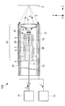
- FIG. 1 is a longitudinal sectional view showing a configuration of an optical fiber scanner according to a first embodiment of the present invention.
- FIG. 1B is a front view of the optical fiber scanner of FIG. 1A viewed from the front end side of the optical fiber. It is a longitudinal cross-sectional view which shows the structure of an observation apparatus provided with the optical fiber scanner of FIG. 1A. It is a longitudinal cross-sectional view which shows the structure of the 1st modification of the optical fiber scanner of FIG. 1A.
- FIG. 3B is a front view of the optical fiber scanner of FIG. 3A viewed from the front end side. It is a longitudinal cross-sectional view which shows the structure of the 2nd modification of the optical fiber scanner of FIG. 1A.
- FIG. 1B is a front view of the optical fiber scanner of FIG. 1A viewed from the front end side of the optical fiber.
- FIG. 4B is a front view of the optical fiber scanner of FIG. 4A viewed from the front end side. It is a longitudinal cross-sectional view which shows the structure of the 3rd modification of the optical fiber scanner of FIG. 1A.
- FIG. 5B is a front view of the optical fiber scanner of FIG. 5A viewed from the front end side. It is a longitudinal cross-sectional view which shows the structure of the optical fiber scanner which concerns on the 2nd Embodiment of this invention.
- FIG. 6B is a front view of the optical fiber scanner of FIG. 6A viewed from the front end side.
- FIG. 4 is a longitudinal sectional view (lower stage) showing a configuration of an optical fiber scanner according to a third embodiment of the present invention, and a longitudinal sectional view (upper stage) of the optical fiber scanner of FIG. 1A.
- FIGS. 1A to 5B An optical fiber scanner 10 according to a first embodiment of the present invention will be described below with reference to FIGS. 1A to 5B.
- an orthogonal coordinate system X, Y, Z is used in which the radial direction of the optical fiber 1 is the X direction and the Y direction, and the longitudinal direction of the optical fiber 1 is the Z direction.
- the optical fiber scanner 10 includes an elongated round bar-shaped optical fiber 1 made of a glass material and vibrations directed toward the outer peripheral surface of the tip portion of the optical fiber 1.
- the vibration transmission member 2 is a quadrangular columnar member made of a metal material such as nickel or copper, and structurally reinforces the flexible optical fiber 1.
- the vibration transmitting member 2 has through holes 5 and 6 formed along the central axis in the longitudinal direction from the front end surface to the base end surface, and the optical fiber 1 passes through the through holes 5 and 6.
- the through hole is composed of a fitting hole 5 and an accommodation hole 6.
- the fitting hole 5 has an inner diameter substantially the same as the outer diameter of the optical fiber 1 and extends from the base end surface of the vibration transmitting member 2 to a midway position in the longitudinal direction.
- the vibration transmitting member 2 is configured such that the outer peripheral surface of the optical fiber 1 fitted in the fitting hole 5 and the inner peripheral surface of the fitting hole 5 are fixed to each other so that the optical fiber 1 is separated at the position of the fitting hole 5. It is held like a cantilever.
- the housing hole 6 has an inner diameter larger than the outer diameter of the optical fiber 1 and extends from the midway position in the longitudinal direction of the vibration transmitting member 2 to the tip surface.
- the portion of the optical fiber 1 that protrudes from the tip opening of the fitting hole 5 that opens to the bottom surface of the receiving hole 6 (hereinafter, this portion is referred to as the tip vibrating portion 1 b) is between the inner peripheral surface of the receiving hole 6. It is accommodated in the accommodation hole 6 with a cylindrical gap.
- the diameter E of the receiving hole 6 is based on the maximum amplitude (maximum value of all amplitudes) D in the X and Y directions of the tip 1a of the optical fiber 1 that vibrates by driving the piezoelectric elements 3A, 3B, 3C, and 3D as will be described later. Is also slightly larger.
- the depth G of the receiving hole 6 is equal to or less than the length F of the tip vibration portion 1b, and the tip 1a of the optical fiber 1 is substantially at the same position as the tip surface of the vibration transmission member 2, or the vibration transmission member 2 It is arrange
- Piezoelectric elements 3A, 3B, 3C, and 3D are plate-shaped members that are formed of a piezoelectric ceramic material such as lead zirconate titanate (PZT) and have a length a. Electrode treatment is applied to the front and back surfaces of the piezoelectric elements 3A, 3B, 3C, and 3D so that the front surface is a positive pole and the rear surface is a negative pole. As a result, the piezoelectric elements 3A, 3B, 3C, and 3D are polarized in the direction from the positive pole to the negative pole as indicated by an arrow P.
- PZT lead zirconate titanate
- the piezoelectric elements 3A, 3B, 3C, 3D are attached one by one to the four side surfaces of the vibration transmitting member 2 with a conductive adhesive or the like with the thickness direction, which is the polarization direction P, oriented in the radial direction of the optical fiber ing.
- a gap C is provided between each of the piezoelectric elements 3A, 3B, 3C, 3D and the holding member 4.
- the two piezoelectric elements 3A and 3B facing each other in the X direction are attached to the vibration transmitting member 2 so that the polarization directions P are the same.
- a piezoelectric element driving lead wire 7 is joined to the piezoelectric elements 3A and 3B by a conductive adhesive.
- the piezoelectric elements 3A and 3B vibrate in the Z direction orthogonal to the polarization direction P.
- one of the two piezoelectric elements 3A and 3B is contracted in the Z direction and the other is expanded in the Z direction, whereby bending vibration in the X direction is generated in the vibration transmitting member 2.
- the tip vibration portion 1 b bends and vibrates in the X direction in the accommodation hole 6.
- the two piezoelectric elements 3C and 3D facing each other in the Y direction are also attached to the vibration transmitting member 2 so that the polarization directions P are the same.
- a piezoelectric element driving lead wire 8 is joined to the piezoelectric elements 3C and 3D by a conductive adhesive. When an alternating voltage of B phase is applied to the piezoelectric elements 3C and 3D via the lead wire 8, the piezoelectric elements 3C and 3D are expanded and contracted in the Z direction orthogonal to the polarization direction P.
- one of the two piezoelectric elements 3 ⁇ / b> C and 3 ⁇ / b> D contracts in the Z direction and the other extends in the Z direction, whereby bending vibration in the Y direction is generated in the vibration transmitting member 2.
- the bending vibration in the Y direction of the vibration transmitting member 2 is transmitted to the optical fiber 1, so that the tip vibration portion 1 b bends and vibrates in the Y direction in the accommodation hole 6.
- the holding member 4 is a member for fixing an intermediate position of the optical fiber 1 to an outer cylinder 12 of the observation apparatus 100 described later.
- the holding member 4 is a cylindrical member formed of a metal material such as stainless steel and having a length b.
- the holding member 4 is fitted to the outer peripheral surface of the base end portion of the vibration transmission member 2 and is fixed to the vibration transmission member 2 with a conductive adhesive.
- the holding member 4 functions as a common ground (GND) when the piezoelectric elements 3A, 3B, 3C, 3D are driven by an alternating voltage.
- the GND lead wire 9 for driving the piezoelectric element is joined to the surface of the holding member 4 via a conductive adhesive. 2 to 7, the lead wires 7, 8, and 9 are not shown.
- the optical fiber scanner 10 configured as described above will be described.
- a bending vibration state in which the amplitude of the tip 1a of the optical fiber 1 is maximized.
- a phase A alternating voltage having a frequency to generate the voltage is applied to the piezoelectric elements 3A and 3B via the lead wire 7.
- linear bending vibration is excited in the X direction in the tip vibration portion 1 b of the optical fiber 1.
- a B-phase alternating voltage having a frequency that generates a bending vibration state (mode) in which the amplitude of the tip 1a of the optical fiber 1 is maximized is applied to the piezoelectric elements 3C and 3D via the lead wires 8.
- a B-phase alternating voltage having a frequency that generates a bending vibration state (mode) in which the amplitude of the tip 1a of the optical fiber 1 is maximized is applied to the piezoelectric elements 3C and 3D via the lead wires 8.
- linear bending vibration is excited in the Y direction in the tip vibration portion 1b of the optical fiber 1.
- the tip 1a of the optical fiber 1 vibrates along a circular locus. Further, when the amplitudes of these two alternating voltages are changed with time in a sine wave shape, the tip 1a of the optical fiber 1 vibrates along a spiral locus. Thereby, the illumination light L can be scanned two-dimensionally along the spiral locus on the subject X.
- the optical fiber scanner 10 according to the present embodiment, all or most of the distal end vibration portion 1b of the optical fiber 1 is accommodated in the accommodation hole 6 formed in the distal end side portion of the vibration transmission member 2. And is vibrated in the accommodation hole 6.
- a portion of the optical fiber scanner 10 from the proximal end surface of the holding member 4 to the distal end 1 a of the optical fiber 1 is shortened.
- This portion is a portion that is disposed at the distal end hard portion of the illumination device or the observation device when the optical fiber scanner 10 is incorporated into the probe-like illumination device or observation device. That is, by using the optical fiber scanner 10 according to the present embodiment, there is an advantage that an illuminating device or an observation device with a short tip hard portion can be realized.
- the observation apparatus 100 including the optical fiber scanner 10 according to the present embodiment is a probe-like observation apparatus such as an endoscope, and as illustrated in FIG. 2, an illumination lens 11 disposed on the distal end side of the optical fiber scanner 10 and an optical fiber.
- An elongated outer cylinder 12 that accommodates the scanner 10 and the illumination lens 11, a plurality of detection optical fibers 13 arranged in the circumferential direction outside the optical fiber scanner 10, and illumination light L is supplied to the proximal end of the optical fiber 1
- a light detector (light detection unit) 15 for detecting light received by the detection optical fiber 13.
- the illumination lens 11 is disposed so that the rear focal position thereof substantially coincides with the tip 1 a of the optical fiber 1.
- the illumination lens 11 receives light emitted from the tip 1 a of the optical fiber 1, converts the received illumination light L into parallel light, emits it as a focused light beam, and condenses it on the subject X.
- a single lens is shown as the illumination lens 11, but the illumination lens 11 may be composed of a plurality of lenses.
- the optical fiber scanner 10 is held in the outer cylinder 12 by fixing the outer peripheral surface of the holding member 4 and the inner peripheral surface of the outer cylinder 12 to each other with an epoxy adhesive.
- the light source 14 is disposed on the proximal end side of the outer cylinder 12, and the proximal end of the optical fiber 1 is connected thereto.
- the photodetector 15 is disposed on the proximal end side of the outer cylinder 12 and is connected to the proximal end of the detection optical fiber 13.
- the distal end 1a of the optical fiber 1 is vibrated spirally with the illumination lens 11 facing the subject X, and the illumination light L is emitted from the light source 14 to the optical fiber 1.
- the illumination light L propagated in the optical fiber 1 is emitted from the tip 1a.
- the emitted illumination light L is converged by the illumination lens 11 and irradiated onto the subject X, and scanned two-dimensionally along the spiral locus on the subject X.
- the return light L ′ of the illumination light L from the subject X is received by the plurality of detection optical fibers 13, and the intensity thereof is detected by the photodetector 15.
- the observation apparatus 100 detects the return light L ′ by the photodetector 15 in synchronization with the scanning period of the illumination light L, and associates the detected intensity of the return light L ′ with the scanning position of the illumination light L, thereby An image of the specimen X is generated.
- the hard distal end portion 16 from the proximal end surface of the holding member 4 to the distal end surface where the illumination lens 11 is disposed is covered with the hard outer cylinder 12.
- the hard tip portion 16 can be shortened.
- the observation apparatus 100 can be easily moved even in a curved portion of a narrow lumen, and there is an advantage that the observation apparatus 100 with high operability can be obtained.
- the observation apparatus 100 including the optical fiber scanner 10 has been described.
- the detection optical fiber 13 and the photodetector 15 are omitted from the configuration described above, and an illumination apparatus having only an illumination function is configured. May be.
- the optical fiber scanner 10 may be modified as in the following first to third modifications.
- a first modification as shown in FIGS. 3A and 3B, a counterbore-shaped recess 4a is formed on the front end surface of the holding member 4, and the piezoelectric elements 3A, 3B, 3C, 3D are arranged inside the recess 4a.
- the base end portions of the piezoelectric elements 3A, 3B, 3C, 3D may be inserted into the recess 4a so as to straddle the outer side.
- the concave portion 4a has a diameter K that satisfies the following formula so that an annular gap is formed around the outer peripheral surface of the base end portion of the piezoelectric elements 3A, 3B, 3C, 3D located in the concave portion 4a.
- I is the distance between the surfaces of the two opposing piezoelectric elements 3A, 3B or 3C, 3D located on the radially outer side. K> ⁇ 2 ⁇ I
- the arrangement of the piezoelectric elements 3A, 3B, 3C, 3D and the holding member 4 may be reversed. That is, the holding member 4 may be provided on the distal end side of the vibration transmission member 2, and the piezoelectric elements 3 ⁇ / b> A, 3 ⁇ / b> B, 3 ⁇ / b> C, 3 ⁇ / b> D may be provided on the proximal end side of the vibration transmission member 2.
- the vibration transmission member 2 may be cylindrical.
- an optical fiber scanner 20 according to a second embodiment of the present invention will be described with reference to FIGS. 6A and 6B.
- the configuration different from the first embodiment will be mainly described, and the common configuration of the first embodiment will be denoted by the same reference numeral and the description thereof will be omitted.
- the optical fiber scanner 20 according to the present embodiment is different from the first embodiment in the shape of the accommodation hole 6.
- the accommodation hole 6 has a truncated cone shape in which the inner diameter gradually increases from the proximal end side to the distal end side of the vibration transmission member 2, and the distal end surface of the vibration transmission member 2
- the diameter H of the opening at is larger than the diameter E of the bottom surface.
- the amplitude of the tip vibrating portion 1b of the optical fiber 1 increases toward the tip side. Therefore, by making the shape of the truncated cone so that the inner diameter of the accommodation hole 6 becomes larger toward the distal end side, it is possible to more effectively prevent contact between the vibrating tip vibration portion 1 b and the inner peripheral surface of the accommodation hole 6. Moreover, when the amplitude of the tip vibration part 1b is the same, the outer diameter of the vibration transmission member 2 can be reduced.
- the amplitude of the tip 1a of the optical fiber 1 can be increased and the scanning range of the illumination light L can be expanded.
- the other effects of the present embodiment are the same as those of the first embodiment, and thus description thereof is omitted.
- the optical fiber scanner 30 according to the present embodiment is similar to the first modification of the first embodiment, and the piezoelectric element 3 ⁇ / b> A is placed in the recess 4 a provided in the holding member 4. , 3B, 3C, 3D are inserted. 7, for comparison with the optical fiber scanner 10 according to the first embodiment, the same one as the optical fiber scanner 10 shown in FIG. 1A is shown in the upper stage, and the optical fiber scanner according to the present embodiment is shown in the lower stage. 30 is illustrated.
- the positions of the piezoelectric elements 3A, 3B, 3C, 3D are shifted toward the base end side by the same distance J as the depth J of the recess 4a.
- the length of the vibration transmitting member 2 is also shortened by the length J, and the position of the bottom surface of the receiving hole 6 is also shifted by the distance J toward the base end side.
- the length F of the distal vibration portion 1b is the same as that of the first embodiment, and the distal end 1a of the optical fiber 1 is also moved by a distance J toward the proximal end side.
- the optical fiber scanner 30 Since the operation of the optical fiber scanner 30 according to this embodiment is the same as that of the first embodiment, description thereof is omitted.
- the optical fiber scanner 30 according to the present embodiment by providing the holding member 4 with the recess 4a, while maintaining the dimensions of the piezoelectric elements 3A, 3B, 3C, 3D and the tip vibrating portion 1b, The positions of 3B, 3C, 3D and the distal end vibration portion 1b can be shifted to the proximal end side, and the portion disposed on the distal end hard portion 16 can be further shortened.
- the optical fiber scanner 10 of 1st Embodiment there exists an advantage that the illuminating device or observation apparatus in which the front-end
- Optical fiber 1a Tip 1b Tip vibration part 2 Vibration transmission member 3A, 3B, 3C, 3D Piezoelectric element 4 Holding member 4a Recess 5 Fitting hole (through hole) 6 accommodation hole (through hole) 7, 8 Lead wire 9 GND lead wires 10, 20, 30 Optical fiber scanner 11 Illumination lens 12 Outer tube 13 Detection optical fiber 14 Light source 15 Photodetector (light detection unit) 16 Hard tip portion 100 Observation device L Illumination light L ′ Return light X Subject
Landscapes
- Physics & Mathematics (AREA)
- Health & Medical Sciences (AREA)
- Life Sciences & Earth Sciences (AREA)
- Optics & Photonics (AREA)
- Surgery (AREA)
- General Physics & Mathematics (AREA)
- Engineering & Computer Science (AREA)
- Medical Informatics (AREA)
- Public Health (AREA)
- Pathology (AREA)
- Biomedical Technology (AREA)
- Heart & Thoracic Surgery (AREA)
- Nuclear Medicine, Radiotherapy & Molecular Imaging (AREA)
- Molecular Biology (AREA)
- Animal Behavior & Ethology (AREA)
- General Health & Medical Sciences (AREA)
- Radiology & Medical Imaging (AREA)
- Veterinary Medicine (AREA)
- Biophysics (AREA)
- Astronomy & Astrophysics (AREA)
- Multimedia (AREA)
- Instruments For Viewing The Inside Of Hollow Bodies (AREA)
- Endoscopes (AREA)
- Mechanical Optical Scanning Systems (AREA)
Abstract
光ファイバスキャナ(10)は、細長い光ファイバ(1)と、長手方向に形成され光ファイバ(1)が貫通する貫通穴(5,6)を有する柱状の振動伝達部材(2)と、該振動伝達部材(2)の外周面に設けられた圧電素子(3A,3B)とを備え、貫通穴(5)が、振動伝達部材(2)の基端面から長手方向の途中位置まで形成され、光ファイバ(1)の外周面に嵌合する嵌合穴からなり、貫通穴(6)が、振動伝達部材(2)の途中位置から先端面まで形成され、光ファイバ(1)の外径よりも大きな内径を有し、光ファイバ(1)の外周面との間に間隔を空けて該光ファイバ(1)の先端部分を収容する収容穴からなる。
Description
本発明は、光ファイバスキャナ、照明装置および観察装置に関するものである。
従来、圧電素子を用いて光ファイバの先端を高速で振動させることにより、光ファイバの先端から射出される光をスパイラル状の軌跡に沿って走査する光ファイバスキャナが知られている(例えば、特許文献1参照。)。特許文献1の光ファイバスキャナは、チタン酸ジルコン酸鉛(PZT)からなる筒状のアクチュエータによって光ファイバを片持ち梁状に保持し、光ファイバの、アクチュエータから突出した先端部分を振動させている。
光ファイバスキャナを内視鏡のようなプローブに搭載する場合、光学設計上、光ファイバスキャナからプローブの先端に配置される照明レンズまでのプローブの先端部分(先端硬質部)を硬質な外筒で被覆する必要がある。このときに、特許文献1の光ファイバスキャナは、光ファイバがアクチュエータから大きく突き出した構造であり、アクチュエータよりも先端側の部分が長くなるため、プローブの先端硬質部が長くなる。先端硬質部が長いと、例えば、狭く湾曲した管腔内において良好な操作性が得られないため、より短い先端硬質部が望まれている。
本発明は、上述した事情に鑑みてなされたものであって、プローブの先端硬質部の短縮を図ることができる光ファイバスキャナ、照明装置および観察装置を提供することを目的とする。
上記目的を達成するため、本発明は以下の手段を提供する。
本発明の第1の態様は、光を導光して先端から射出可能な細長い光ファイバと、長手方向に形成され前記光ファイバが貫通する貫通穴を有する柱状の振動伝達部材と、該振動伝達部材の外周面に設けられ、交番電圧の印加によって前記光ファイバの長手方向に伸縮振動することにより前記振動伝達部材に前記長手方向に交差する方向の屈曲振動を発生させる圧電素子とを備え、前記貫通穴が、前記振動伝達部材の基端面から長手方向の途中位置まで形成され、前記光ファイバの外周面に嵌合する嵌合穴と、前記振動伝達部材の前記途中位置から先端面まで形成され、前記光ファイバの外径よりも大きな内径を有し、前記光ファイバの外周面との間に間隔を空けて該光ファイバの先端部分を収容する収容穴とからなる光ファイバスキャナである。
本発明の第1の態様は、光を導光して先端から射出可能な細長い光ファイバと、長手方向に形成され前記光ファイバが貫通する貫通穴を有する柱状の振動伝達部材と、該振動伝達部材の外周面に設けられ、交番電圧の印加によって前記光ファイバの長手方向に伸縮振動することにより前記振動伝達部材に前記長手方向に交差する方向の屈曲振動を発生させる圧電素子とを備え、前記貫通穴が、前記振動伝達部材の基端面から長手方向の途中位置まで形成され、前記光ファイバの外周面に嵌合する嵌合穴と、前記振動伝達部材の前記途中位置から先端面まで形成され、前記光ファイバの外径よりも大きな内径を有し、前記光ファイバの外周面との間に間隔を空けて該光ファイバの先端部分を収容する収容穴とからなる光ファイバスキャナである。
本発明の第1の態様によれば、圧電素子に交番電圧が印加されて振動伝達部材が屈曲振動すると、この屈曲振動が、光ファイバの、嵌合穴に嵌合している部分から、嵌合穴から先端側に片持ち梁状に突出した部分(先端振動部)に伝達され、光ファイバの先端が長手方向に交差する方向に振動する。これにより、光ファイバの先端から射出される照明光を該照明光の進行方向に交差する方向に走査することができる。
この場合に、光ファイバの先端振動部の少なくとも一部が、振動伝達部材の先端側部分に形成された収容穴に収容され該収容穴内で屈曲振動する構造となっているので、光ファイバの振動伝達部材の先端面からの突出量が小さくなる。これにより、光ファイバスキャナが搭載される内視鏡のようなプローブの先端硬質部に対応する、振動伝達部材の基端面から光ファイバの先端面までの部分を短縮し、プローブの先端硬質部の短縮を図ることができる。
上記第1の態様においては、前記圧電素子が、前記途中位置を前記長手方向に跨がって設けられていてもよく、前記振動伝達部材の先端または該先端の近傍を含む位置に設けられていてもよい。
このようにすることで、振動伝達部材の長手方向の寸法を有効に利用して圧電素子を設けることによって、圧電素子の伸縮振動を振動伝達部材によって効率的に光ファイバに伝達することができる。
このようにすることで、振動伝達部材の長手方向の寸法を有効に利用して圧電素子を設けることによって、圧電素子の伸縮振動を振動伝達部材によって効率的に光ファイバに伝達することができる。
上記第1の態様においては、前記収容穴が、前記光ファイバの先端の前記交差する方向の最大振幅よりも大きな直径と、前記光ファイバの前記嵌合穴から先端側に突出した部分の長さと同等またはそれ以下の深さとを有する円筒状であってもよい。
このようにすることで、光ファイバの先端振動部を、収容穴の内壁に接触させることなく収容穴内で振動させることができる。
このようにすることで、光ファイバの先端振動部を、収容穴の内壁に接触させることなく収容穴内で振動させることができる。
上記第1の態様においては、前記収容穴が、基端側から先端側に向かって内径が漸次大きくなる錐台状であってもよい。
このようにすることで、先端振動部の振動振幅が大きくなる先端側程、収容穴の内径を大きくすることによって、先端振動部の収容穴の内壁との接触をさらに効果的に防ぐことができる。
このようにすることで、先端振動部の振動振幅が大きくなる先端側程、収容穴の内径を大きくすることによって、先端振動部の収容穴の内壁との接触をさらに効果的に防ぐことができる。
上記第1の態様においては、前記振動伝達部材の基端部分の外周面を保持する筒状の保持部材を備え、該保持部材が、先端側の端面に設けられ、前記振動伝達部材の外周面との間に、前記圧電素子の前記光ファイバの径方向の寸法よりも大きな幅の隙間を形成する凹部を有し、前記圧電素子の基端部分が、前記凹部内に配置されていてもよい。
このようにすることで、圧電素子、収容穴および先端振動部の位置を全体的に基端側へずらし、振動伝達部材の基端面から光ファイバの先端面までの部分をさらに短縮することができる。
このようにすることで、圧電素子、収容穴および先端振動部の位置を全体的に基端側へずらし、振動伝達部材の基端面から光ファイバの先端面までの部分をさらに短縮することができる。
本発明の第2の態様は、上記いずれかに記載の光ファイバスキャナと、該光ファイバスキャナの基端側に配置され前記光ファイバに照明光を供給する光源と、前記光ファイバスキャナの先端側に配置され前記光ファイバの先端から射出される光を被検体に集光する照明レンズと、前記光ファイバスキャナおよび前記照明レンズを収容する細長い外筒とを備える照明装置である。
本発明の第3の態様は、上記に記載の照明装置と、該照明装置によって光が被検体に照射されることにより前記被検体から戻る戻り光を検出する光検出部とを備える観察装置である。
本発明の第3の態様は、上記に記載の照明装置と、該照明装置によって光が被検体に照射されることにより前記被検体から戻る戻り光を検出する光検出部とを備える観察装置である。
本発明によれば、プローブの先端硬質部の短縮を図ることができるという効果を奏する。
(第1の実施形態)
本発明の第1の実施形態に係る光ファイバスキャナ10について、図1Aから図5Bを参照して以下に説明する。なお、本実施形態の説明において、光ファイバ1の径方向をX方向およびY方向とし、光ファイバ1の長手方向をZ方向とする直交座標系X,Y,Zを用いる。
本発明の第1の実施形態に係る光ファイバスキャナ10について、図1Aから図5Bを参照して以下に説明する。なお、本実施形態の説明において、光ファイバ1の径方向をX方向およびY方向とし、光ファイバ1の長手方向をZ方向とする直交座標系X,Y,Zを用いる。
本実施形態に係る光ファイバスキャナ10は、図1Aおよび図1Bに示されるように、ガラス材料からなる細長い丸棒状の光ファイバ1と、該光ファイバ1の先端部分の外周面に向けられた振動伝達部材2と、該振動伝達部材2の外周面に設けられた板状の圧電素子3A,3B,3C,3Dと、保持部材4とを備えている。
振動伝達部材2は、ニッケルまたは銅などの金属材料からなる四角柱状の部材であり、可撓性の光ファイバ1を構造的に補強している。振動伝達部材2は、先端面から基端面までその長手方向の中心軸に沿って形成された貫通穴5,6を有し、該貫通穴5,6内に光ファイバ1が貫通している。この貫通穴は、嵌合穴5と収容穴6とからなる。
嵌合穴5は、光ファイバ1の外径と略同一の内径を有し、振動伝達部材2の基端面から長手方向の途中位置まで延びている。振動伝達部材2は、嵌合穴5に嵌合した光ファイバ1の外周面と嵌合穴5の内周面とが互いに固定されることにより、嵌合穴5の位置で光ファイバ1を片持ち梁状に保持している。
収容穴6は、光ファイバ1の外径よりも大きな内径を有し、振動伝達部材2の前記長手方向の途中位置から先端面まで延びている。光ファイバ1の、収容穴6の底面に開口する嵌合穴5の先端開口から突出した部分(以下、この部分を先端振動部1bという。)は、収容穴6の内周面との間に円筒状の隙間を空けて収容穴6内に収容されている。収容穴6の直径Eは、後述するように圧電素子3A,3B,3C,3Dの駆動によって振動する光ファイバ1の先端1aのX方向およびY方向の最大振幅(全振幅の最大値)Dよりもわずかに大きい。収容穴6の深さGは、先端振動部1bの長さFと同等またはそれ以下であり、光ファイバ1の先端1aは振動伝達部材2の先端面と略同じ位置、または、振動伝達部材2の先端面よりもわずかに突出した位置に配置されている。
圧電素子3A,3B,3C,3Dは、チタン酸ジルコン酸鉛(PZT)等の圧電セラミックス材料から形成され、長さaを有する板状の部材である。圧電素子3A,3B,3C,3Dのおもて面と裏面にはそれぞれ、おもて面が+極、裏面が-極となるように電極処理が施されている。これにより、圧電素子3A,3B,3C,3Dには、矢印Pで示されるように、+極から-極に向かう方向の分極が施されている。圧電素子3A,3B,3C,3Dは、分極方向Pである厚さ方向を光ファイバ1の径方向に向け、振動伝達部材2の4つの側面に導電性接着剤等によって1枚ずつ貼り付けられている。各圧電素子3A,3B,3C,3Dと保持部材4との間には、隙間Cが設けられている。
ここで、X方向に互いに対向する2枚の圧電素子3A,3Bは、分極方向Pが同一となるように振動伝達部材2に貼り付けられている。圧電素子3A,3Bには、圧電素子駆動用のリード線7が導電性接着剤によって接合されている。リード線7を介して圧電素子3A,3BにA相の交番電圧が印加されると、圧電素子3A,3Bは、分極方向Pに直交するZ方向に伸縮振動する。このときに、2枚の圧電素子3A,3Bのうち、一方がZ方向に縮み、他方がZ方向に伸びることにより、振動伝達部材2にX方向の屈曲振動が発生する。この振動伝達部材2のX方向の屈曲振動が光ファイバ1に伝達されることにより、先端振動部1bが収容穴6内でX方向に屈曲振動する。
同様に、Y方向に互いに対向する2枚の圧電素子3C,3Dも、分極方向Pが同一となるように振動伝達部材2に貼り付けられている。圧電素子3C,3Dには、圧電素子駆動用のリード線8が導電性接着剤によって接合されている。リード線8を介して圧電素子3C,3DにB相の交番電圧が印加されると、圧電素子3C,3Dは、分極方向Pに直交するZ方向に伸縮振動する。このときに、2枚の圧電素子3C,3Dのうち、一方がZ方向に縮み、他方がZ方向に伸びることにより、振動伝達部材2にY方向の屈曲振動が発生する。この振動伝達部材2のY方向の屈曲振動が光ファイバ1に伝達されることにより、先端振動部1bが収容穴6内でY方向に屈曲振動する。
保持部材4は、光ファイバ1の途中位置を後述する観察装置100の外筒12に対して固定するための部材である。保持部材4は、ステンレス等の金属材料から形成され、長さbを有する円筒状の部材である。保持部材4は、振動伝達部材2の基端部分の外周面に嵌合して導電性接着剤によって振動伝達部材2に固定されている。ここで、保持部材4は、交番電圧によって圧電素子3A,3B,3C,3Dを駆動する際の共通グランド(GND)として機能する。この理由から、圧電素子駆動用のGNDリード線9が保持部材4の表面に導電性接着剤を介して接合されている。
なお、図2から図7において、リード線7,8,9の図示は省略している。
なお、図2から図7において、リード線7,8,9の図示は省略している。
次に、このように構成された光ファイバスキャナ10の作用について説明する。
本実施形態に係る光ファイバスキャナ10によって、光源から光ファイバ1に供給された照明光を被検体上で走査するには、光ファイバ1の先端1aの振幅が最大となる屈曲振動状態(モード)を生成する周波数を有するA相の交番電圧を、リード線7を介して圧電素子3A,3Bに印加する。これにより、光ファイバ1の先端振動部1bに、直線状の屈曲振動がX方向に励起される。
本実施形態に係る光ファイバスキャナ10によって、光源から光ファイバ1に供給された照明光を被検体上で走査するには、光ファイバ1の先端1aの振幅が最大となる屈曲振動状態(モード)を生成する周波数を有するA相の交番電圧を、リード線7を介して圧電素子3A,3Bに印加する。これにより、光ファイバ1の先端振動部1bに、直線状の屈曲振動がX方向に励起される。
同様に、光ファイバ1の先端1aの振幅が最大となる屈曲振動状態(モード)を生成する周波数を有するB相の交番電圧を、リード線8を介して圧電素子3C,3Dに印加する。これにより、光ファイバ1の先端振動部1bに、直線状の屈曲振動がY方向に励起される。
ここで、圧電素子3A,3Bと圧電素子3C,3Dとに、互いに位相がπ/2だけずれた交番電圧を同時に印加すると、光ファイバ1の先端1aが円状の軌跡に沿って振動する。さらに、これら2つの交番電圧の振幅を正弦波状に時間変化させると、光ファイバ1の先端1aがスパイラル状の軌跡に沿って振動する。これにより、被検体X上において照明光Lをスパイラル状の軌跡に沿って2次元的に走査することができる。
この場合に、本実施形態に係る光ファイバスキャナ10によれば、光ファイバ1の先端振動部1bの全部または大部分が、振動伝達部材2の先端側部分に形成された収容穴6内に収容され、この収容穴6内で振動させられる。このように、振動伝達部材2から光ファイバ1がほとんど突出しない構造とすることによって、光ファイバスキャナ10のうち、保持部材4の基端面から光ファイバ1の先端1aまでの部分が短くなる。この部分は、光ファイバスキャナ10をプローブ状の照明装置または観察装置に組み込む際に、照明装置または観察装置の先端硬質部に配置される部分である。すなわち、本実施形態に係る光ファイバスキャナ10を用いることにより、先端硬質部の短い照明装置または観察装置を実現することができるという利点がある。
次に、本実施形態に係る光ファイバスキャナ10を備える観察装置100について説明する。
本実施形態に係る観察装置100は、内視鏡のようなプローブ状の観察装置であり、図2に示されるように、光ファイバスキャナ10の先端側に配置された照明レンズ11と、光ファイバスキャナ10および照明レンズ11を収容する細長い外筒12と、光ファイバスキャナ10の外側に周方向に配列された複数本の検出用光ファイバ13と、光ファイバ1の基端に照明光Lを供給する光源14と、検出用光ファイバ13によって受光された光を検出する光検出器(光検出部)15とを備えている。
本実施形態に係る観察装置100は、内視鏡のようなプローブ状の観察装置であり、図2に示されるように、光ファイバスキャナ10の先端側に配置された照明レンズ11と、光ファイバスキャナ10および照明レンズ11を収容する細長い外筒12と、光ファイバスキャナ10の外側に周方向に配列された複数本の検出用光ファイバ13と、光ファイバ1の基端に照明光Lを供給する光源14と、検出用光ファイバ13によって受光された光を検出する光検出器(光検出部)15とを備えている。
照明レンズ11は、その後側焦点位置が光ファイバ1の先端1aと略一致するように配置されている。照明レンズ11は、光ファイバ1の先端1aから射出される光を受光し、受光した照明光Lを平行光に変換した後に集束光束として射出して被検体X上に集光させる。なお、図2には、照明レンズ11として単一のレンズが示されているが、照明レンズ11は、複数のレンズから構成されていてもよい。
光ファイバスキャナ10は、保持部材4の外周面と外筒12の内周面とがエポキシ系の接着剤によって互いに固定されることにより、外筒12内に保持されている。
光源14は、外筒12の基端側に配置され、光ファイバ1の基端が接続されている。
光検出器15は、外筒12の基端側に配置され、検出用光ファイバ13の基端が接続されている。
光源14は、外筒12の基端側に配置され、光ファイバ1の基端が接続されている。
光検出器15は、外筒12の基端側に配置され、検出用光ファイバ13の基端が接続されている。
このように構成された観察装置100によれば、照明レンズ11を被検体Xに対向配置した状態で光ファイバ1の先端1aをスパイラル状に振動させ、光源14から光ファイバ1に照明光Lを供給すると、光ファイバ1内を伝搬した照明光Lが先端1aから射出される。射出された照明光Lは、照明レンズ11によって収束して被検体Xに照射され、被検体X上においてスパイラル状の軌跡に沿って2次元的に走査される。
被検体Xからの照明光Lの戻り光L’は、複数本の検出用光ファイバ13によって受光され、その強度が光検出器15によって検出される。観察装置100は、照明光Lの走査周期と同期して光検出器15によって戻り光L’を検出し、検出された戻り光L’の強度を照明光Lの走査位置と対応付けることにより、被検体Xの画像を生成する。
この場合に、本実施形態に係る観察装置100によれば、保持部材4の基端面から照明レンズ11が配置される先端面までの先端硬質部16は、硬質な外筒12によって被覆される。上述したように光ファイバスキャナ10の、先端硬質部16に配置される部分は短いので、先端硬質部16を短くすることができる。これにより、例えば、狭い管腔の湾曲した部分においても観察装置100を容易に移動させることができ、操作性の高い観察装置100を得ることができるという利点がある。
本実施形態においては、光ファイバスキャナ10を備える観察装置100について説明したが、上述した構成のうち検出用光ファイバ13および光検出器15を省略して、照明機能のみを備える照明装置を構成してもよい。
本実施形態に係る光ファイバスキャナ10は、以下の第1から第3の変形例のように変形してもよい。
第1の変形例として、図3Aおよび図3Bに示されるように、保持部材4の先端面に座ぐり穴状の凹部4aが形成され、圧電素子3A,3B,3C,3Dが凹部4aの内側と外側とに跨がるように、圧電素子3A,3B,3C,3Dの基端部分が凹部4a内に挿入されていてもよい。凹部4aは、該凹部4a内に位置する圧電素子3A,3B,3C,3Dの基端部分の外周面の周囲に環状の隙間が形成されるように、下式を満たす直径Kを有する。ただし、下式において、Iは、対向する2枚の圧電素子3A,3Bまたは3C,3Dの、半径方向外側に位置する面同士の間の距離である。
K > √2×I
第1の変形例として、図3Aおよび図3Bに示されるように、保持部材4の先端面に座ぐり穴状の凹部4aが形成され、圧電素子3A,3B,3C,3Dが凹部4aの内側と外側とに跨がるように、圧電素子3A,3B,3C,3Dの基端部分が凹部4a内に挿入されていてもよい。凹部4aは、該凹部4a内に位置する圧電素子3A,3B,3C,3Dの基端部分の外周面の周囲に環状の隙間が形成されるように、下式を満たす直径Kを有する。ただし、下式において、Iは、対向する2枚の圧電素子3A,3Bまたは3C,3Dの、半径方向外側に位置する面同士の間の距離である。
K > √2×I
第2の変形例として、図4Aおよび図4Bに示されるように、圧電素子3A,3B,3C,3Dと保持部材4との配置が逆であってもよい。すなわち、保持部材4が振動伝達部材2の先端側に設けられ、圧電素子3A,3B,3C,3Dが、振動伝達部材2の基端側に設けられていてもよい。
第3の変形例として、図5Aおよび図5Bに示されるように、振動伝達部材2が、円柱状であってもよい。
第3の変形例として、図5Aおよび図5Bに示されるように、振動伝達部材2が、円柱状であってもよい。
(第2の実施形態)
次に、本発明の第2の実施形態に係る光ファイバスキャナ20について図6Aおよび図6Bを参照して説明する。なお、本実施形態においては、第1の実施形態と異なる構成について主に説明し、第1の実施形態の共通の構成については同一の符号を付して説明を省略する。
本実施形態に係る光ファイバスキャナ20は、図6Aおよび図6Bに示されるように、収容穴6の形状が第1の実施形態と異なる。
次に、本発明の第2の実施形態に係る光ファイバスキャナ20について図6Aおよび図6Bを参照して説明する。なお、本実施形態においては、第1の実施形態と異なる構成について主に説明し、第1の実施形態の共通の構成については同一の符号を付して説明を省略する。
本実施形態に係る光ファイバスキャナ20は、図6Aおよび図6Bに示されるように、収容穴6の形状が第1の実施形態と異なる。
具体的には、収容穴6は、図6Aに示されるように、振動伝達部材2の基端側から先端側に向かって内径が漸次大きくなる円錐台状であり、振動伝達部材2の先端面における開口の直径Hは、底面の直径Eよりも大きくなっている。
本実施形態に係る光ファイバスキャナ20の作用は、第1の実施形態と同様であるので、説明を省略する。
本実施形態に係る光ファイバスキャナ20によれば、光ファイバ1の先端振動部1bの振幅は、先端側程大きくなる。したがって、収容穴6の内径も先端側程大きくなるように円錐台状とすることにより、振動する先端振動部1bと収容穴6の内周面との接触をより効果的に防ぐことができる。また、先端振動部1bの振幅が同一である場合には、振動伝達部材2の外径を縮小することができる。また、振動伝達部材2の外径が同一である場合には、光ファイバ1の先端1aの振幅をより大きくし、照明光Lの走査範囲を拡大することができる。本実施形態のその他の効果は、第1の実施形態と同じであるので説明を省略する。
本実施形態に係る光ファイバスキャナ20によれば、光ファイバ1の先端振動部1bの振幅は、先端側程大きくなる。したがって、収容穴6の内径も先端側程大きくなるように円錐台状とすることにより、振動する先端振動部1bと収容穴6の内周面との接触をより効果的に防ぐことができる。また、先端振動部1bの振幅が同一である場合には、振動伝達部材2の外径を縮小することができる。また、振動伝達部材2の外径が同一である場合には、光ファイバ1の先端1aの振幅をより大きくし、照明光Lの走査範囲を拡大することができる。本実施形態のその他の効果は、第1の実施形態と同じであるので説明を省略する。
(第3の実施形態)
次に、本発明の第3の実施形態に係る光ファイバスキャナ30について図7を参照して説明する。なお、本実施形態においては、第1の実施形態と異なる構成について主に説明し、第1の実施形態の共通の構成については同一の符号を付して説明を省略する。
次に、本発明の第3の実施形態に係る光ファイバスキャナ30について図7を参照して説明する。なお、本実施形態においては、第1の実施形態と異なる構成について主に説明し、第1の実施形態の共通の構成については同一の符号を付して説明を省略する。
本実施形態に係る光ファイバスキャナ30は、図7に示されるように、第1の実施形態の第1の変形例と類似しており、保持部材4に設けられた凹部4a内に圧電素子3A,3B,3C,3Dの基端側部分が挿入されている。図7においては、第1の実施形態に係る光ファイバスキャナ10と比較するために、上段に図1Aに示される光ファイバスキャナ10と同じものを図示し、下段に本実施形態に係る光ファイバスキャナ30を図示している。
光ファイバスキャナ30において、凹部4aの深さJと同じ距離Jだけ、圧電素子3A,3B,3C,3Dの位置が基端側にずれている。また、振動伝達部材2の長さも長さJだけ短くなっており、収容穴6の底面の位置も基端側に距離Jだけずれている。ここで、先端振動部1bの長さFは第1の実施形態と同じであり、光ファイバ1の先端1aも、基端側に距離Jだけ移動している。
本実施形態に係る光ファイバスキャナ30の作用は、第1の実施形態と同じであるので説明を省略する。
本実施形態に係る光ファイバスキャナ30によれば、保持部材4に凹部4aを設けることによって、圧電素子3A,3B,3C,3Dおよび先端振動部1bの寸法を維持しながら、これら圧電素子3A,3B,3C,3Dおよび先端振動部1bの位置を基端側にずらすことができ、先端硬質部16に配置される部分をさらに短くすることができる。これにより、第1の実施形態の光ファイバスキャナ10と比べて、さらに先端硬質部16の短い照明装置または観察装置を実現することができるという利点がある。
本実施形態に係る光ファイバスキャナ30によれば、保持部材4に凹部4aを設けることによって、圧電素子3A,3B,3C,3Dおよび先端振動部1bの寸法を維持しながら、これら圧電素子3A,3B,3C,3Dおよび先端振動部1bの位置を基端側にずらすことができ、先端硬質部16に配置される部分をさらに短くすることができる。これにより、第1の実施形態の光ファイバスキャナ10と比べて、さらに先端硬質部16の短い照明装置または観察装置を実現することができるという利点がある。
1 光ファイバ
1a 先端
1b 先端振動部
2 振動伝達部材
3A,3B,3C,3D 圧電素子
4 保持部材
4a 凹部
5 嵌合穴(貫通穴)
6 収容穴(貫通穴)
7,8 リード線
9 GNDリード線
10,20,30 光ファイバスキャナ
11 照明レンズ
12 外筒
13 検出用光ファイバ
14 光源
15 光検出器(光検出部)
16 先端硬質部
100 観察装置
L 照明光
L’ 戻り光
X 被検体
1a 先端
1b 先端振動部
2 振動伝達部材
3A,3B,3C,3D 圧電素子
4 保持部材
4a 凹部
5 嵌合穴(貫通穴)
6 収容穴(貫通穴)
7,8 リード線
9 GNDリード線
10,20,30 光ファイバスキャナ
11 照明レンズ
12 外筒
13 検出用光ファイバ
14 光源
15 光検出器(光検出部)
16 先端硬質部
100 観察装置
L 照明光
L’ 戻り光
X 被検体
Claims (8)
- 光を導光して先端から射出可能な細長い光ファイバと、
長手方向に形成され前記光ファイバが貫通する貫通穴を有する柱状の振動伝達部材と、
該振動伝達部材の外周面に設けられ、交番電圧の印加によって前記光ファイバの長手方向に伸縮振動することにより前記振動伝達部材に前記長手方向に交差する方向の屈曲振動を発生させる圧電素子とを備え、
前記貫通穴が、前記振動伝達部材の基端面から長手方向の途中位置まで形成され、前記光ファイバの外周面に嵌合する嵌合穴と、前記振動伝達部材の前記途中位置から先端面まで形成され、前記光ファイバの外径よりも大きな内径を有し、前記光ファイバの外周面との間に間隔を空けて該光ファイバの先端部分を収容する収容穴とからなる光ファイバスキャナ。 - 前記圧電素子が、前記途中位置を前記長手方向に跨がって設けられている請求項1に記載の光ファイバスキャナ。
- 前記圧電素子が、前記振動伝達部材の先端または該先端の近傍を含む位置に設けられている請求項1または請求項2に記載の光ファイバスキャナ。
- 前記収容穴が、前記光ファイバの先端の前記交差する方向の最大振幅よりも大きな直径と、前記光ファイバの前記嵌合穴から先端側に突出した部分の長さと同等またはそれ以下の深さとを有する円筒状である請求項1から請求項3のいずれかに記載の光ファイバスキャナ。
- 前記収容穴が、基端側から先端側に向かって内径が漸次大きくなる錐台状である請求項1から請求項3のいずれかに記載の光ファイバスキャナ。
- 前記振動伝達部材の基端部分の外周面を保持する筒状の保持部材を備え、
該保持部材が、先端側の端面に設けられ、前記振動伝達部材の外周面との間に、前記圧電素子の前記光ファイバの径方向の寸法よりも大きな幅の隙間を形成する凹部を有し、
前記圧電素子の基端部分が、前記凹部内に配置されている請求項1から請求項5のいずれかに記載の光ファイバスキャナ。 - 請求項1から請求項6のいずれかに記載の光ファイバスキャナと、
該光ファイバスキャナの基端側に配置され、前記光ファイバに照明光を供給する光源と、
前記光ファイバスキャナの先端側に配置され、前記光ファイバの先端から射出される光を被検体に集光する照明レンズと、
前記光ファイバスキャナおよび前記照明レンズを収容する細長い外筒とを備える照明装置。 - 請求項7に記載の照明装置と、
該照明装置によって光が被検体に照射されることにより前記被検体から戻る戻り光を検出する光検出部とを備える観察装置。
Priority Applications (3)
| Application Number | Priority Date | Filing Date | Title |
|---|---|---|---|
| CN201580009750.8A CN106028906B (zh) | 2014-02-26 | 2015-02-02 | 光纤扫描器、照明装置和观察装置 |
| DE112015000362.2T DE112015000362T5 (de) | 2014-02-26 | 2015-02-02 | Lichtleiter-Scanner, Beleuchtungsvorrichtung und Beobachtungsvorrichtung |
| US15/199,254 US9874739B2 (en) | 2014-02-26 | 2016-06-30 | Optical fiber scanner, illumination apparatus, and observation apparatus |
Applications Claiming Priority (2)
| Application Number | Priority Date | Filing Date | Title |
|---|---|---|---|
| JP2014-035654 | 2014-02-26 | ||
| JP2014035654A JP6345946B2 (ja) | 2014-02-26 | 2014-02-26 | 光ファイバスキャナ、照明装置および観察装置 |
Related Child Applications (1)
| Application Number | Title | Priority Date | Filing Date |
|---|---|---|---|
| US15/199,254 Continuation US9874739B2 (en) | 2014-02-26 | 2016-06-30 | Optical fiber scanner, illumination apparatus, and observation apparatus |
Publications (1)
| Publication Number | Publication Date |
|---|---|
| WO2015129391A1 true WO2015129391A1 (ja) | 2015-09-03 |
Family
ID=54008717
Family Applications (1)
| Application Number | Title | Priority Date | Filing Date |
|---|---|---|---|
| PCT/JP2015/052819 WO2015129391A1 (ja) | 2014-02-26 | 2015-02-02 | 光ファイバスキャナ、照明装置および観察装置 |
Country Status (5)
| Country | Link |
|---|---|
| US (1) | US9874739B2 (ja) |
| JP (1) | JP6345946B2 (ja) |
| CN (1) | CN106028906B (ja) |
| DE (1) | DE112015000362T5 (ja) |
| WO (1) | WO2015129391A1 (ja) |
Families Citing this family (6)
| Publication number | Priority date | Publication date | Assignee | Title |
|---|---|---|---|---|
| JPWO2017158924A1 (ja) * | 2016-03-17 | 2019-05-16 | オリンパス株式会社 | 走査型内視鏡 |
| AU2017382871A1 (en) * | 2016-12-22 | 2019-06-13 | Magic Leap, Inc. | Methods and systems for fabrication of shaped fiber elements for scanning fiber displays |
| CN109212746A (zh) * | 2017-07-06 | 2019-01-15 | 成都理想境界科技有限公司 | 一种光纤扫描器及光纤扫描成像系统 |
| WO2020006011A1 (en) * | 2018-06-26 | 2020-01-02 | Magic Leap, Inc. | Hybrid optical fiber mems scanner |
| WO2020006008A1 (en) | 2018-06-26 | 2020-01-02 | Magic Leap, Inc. | Raster scanned projector with microelectromechanical system scanner |
| CN111258057A (zh) * | 2018-11-30 | 2020-06-09 | 成都理想境界科技有限公司 | 一种扫描驱动器及光纤扫描器 |
Citations (2)
| Publication number | Priority date | Publication date | Assignee | Title |
|---|---|---|---|---|
| JP2001327460A (ja) * | 2000-05-18 | 2001-11-27 | Olympus Optical Co Ltd | 内視鏡装置 |
| JP2008531193A (ja) * | 2005-02-28 | 2008-08-14 | ユニヴァーシティ オブ ワシントン | バレット食道検診用のテザー付きカプセル内視鏡 |
Family Cites Families (10)
| Publication number | Priority date | Publication date | Assignee | Title |
|---|---|---|---|---|
| US6004499A (en) * | 1997-03-06 | 1999-12-21 | Face International Corporation | Method of aligning fibrous components of composite materials using opposed oscillating reflectors |
| US6975898B2 (en) * | 2000-06-19 | 2005-12-13 | University Of Washington | Medical imaging, diagnosis, and therapy using a scanning single optical fiber system |
| US7616986B2 (en) | 2001-05-07 | 2009-11-10 | University Of Washington | Optical fiber scanner for performing multimodal optical imaging |
| US7333700B2 (en) * | 2006-06-01 | 2008-02-19 | University Of Washington | Scanning apparatus and endoscope |
| US20080039693A1 (en) * | 2006-08-14 | 2008-02-14 | University Of Washington | Endoscope tip unit and endoscope with scanning optical fiber |
| US7583872B2 (en) * | 2007-04-05 | 2009-09-01 | University Of Washington | Compact scanning fiber device |
| CN101444416B (zh) * | 2008-12-26 | 2010-09-08 | 华中科技大学 | 一种光纤扫描探头及其驱动方法 |
| EP2653091B1 (en) * | 2011-03-31 | 2015-06-10 | Olympus Medical Systems Corp. | Scanning endoscope device |
| JP2013158445A (ja) * | 2012-02-03 | 2013-08-19 | Hoya Corp | 走査型プローブ、走査型観察システム、一体型内視鏡、及び一体型内視鏡システム |
| EP2905648A4 (en) * | 2012-10-01 | 2016-06-22 | Olympus Corp | FIBER OPTIC SCANNING DEVICE |
-
2014
- 2014-02-26 JP JP2014035654A patent/JP6345946B2/ja active Active
-
2015
- 2015-02-02 CN CN201580009750.8A patent/CN106028906B/zh not_active Expired - Fee Related
- 2015-02-02 WO PCT/JP2015/052819 patent/WO2015129391A1/ja active Application Filing
- 2015-02-02 DE DE112015000362.2T patent/DE112015000362T5/de not_active Withdrawn
-
2016
- 2016-06-30 US US15/199,254 patent/US9874739B2/en active Active
Patent Citations (2)
| Publication number | Priority date | Publication date | Assignee | Title |
|---|---|---|---|---|
| JP2001327460A (ja) * | 2000-05-18 | 2001-11-27 | Olympus Optical Co Ltd | 内視鏡装置 |
| JP2008531193A (ja) * | 2005-02-28 | 2008-08-14 | ユニヴァーシティ オブ ワシントン | バレット食道検診用のテザー付きカプセル内視鏡 |
Also Published As
| Publication number | Publication date |
|---|---|
| CN106028906A (zh) | 2016-10-12 |
| JP6345946B2 (ja) | 2018-06-20 |
| US9874739B2 (en) | 2018-01-23 |
| US20160377857A1 (en) | 2016-12-29 |
| DE112015000362T5 (de) | 2016-10-06 |
| CN106028906B (zh) | 2018-12-07 |
| JP2015159890A (ja) | 2015-09-07 |
Similar Documents
| Publication | Publication Date | Title |
|---|---|---|
| WO2015129391A1 (ja) | 光ファイバスキャナ、照明装置および観察装置 | |
| JP6498214B2 (ja) | 光ファイバスキャナ、照明装置および観察装置 | |
| JP6129050B2 (ja) | 光ファイバスキャナ、照明装置および観察装置 | |
| JP6274949B2 (ja) | 光ファイバスキャナ、照明装置および観察装置 | |
| WO2016075758A1 (ja) | 光ファイバスキャナ、照明装置および観察装置 | |
| US10330916B2 (en) | Optical-fiber scanner, illumination apparatus, and observation apparatus | |
| WO2018109883A1 (ja) | 光ファイバスキャナ、照明装置および観察装置 | |
| US20180252910A1 (en) | Optical fiber scanner, illumination device, and observation device | |
| JP6865221B2 (ja) | 光ファイバスキャナ、照明装置および観察装置 | |
| WO2017068924A1 (ja) | 光ファイバスキャナ、照明装置および観察装置 | |
| WO2016170612A1 (ja) | 光ファイバスキャナおよび走査型観察装置 | |
| WO2016189627A1 (ja) | 光ファイバスキャナ、照明装置および観察装置 | |
| WO2017068651A1 (ja) | 光ファイバスキャナ、照明装置および観察装置 | |
| WO2017183157A1 (ja) | 光ファイバスキャナ、照明装置および観察装置 | |
| WO2020044541A1 (ja) | 光ファイバスキャナ、照明装置および観察装置 | |
| JPWO2018073948A1 (ja) | 光ファイバスキャナ、照明装置および観察装置 | |
| WO2020044528A1 (ja) | 光ファイバスキャナ、照明装置および観察装置 | |
| US20190029507A1 (en) | Optical fiber scanner, illumination device, and observation device |
Legal Events
| Date | Code | Title | Description |
|---|---|---|---|
| 121 | Ep: the epo has been informed by wipo that ep was designated in this application |
Ref document number: 15755809 Country of ref document: EP Kind code of ref document: A1 |
|
| WWE | Wipo information: entry into national phase |
Ref document number: 112015000362 Country of ref document: DE |
|
| 122 | Ep: pct application non-entry in european phase |
Ref document number: 15755809 Country of ref document: EP Kind code of ref document: A1 |