WO2015129357A1 - エンジン作業機 - Google Patents
エンジン作業機 Download PDFInfo
- Publication number
- WO2015129357A1 WO2015129357A1 PCT/JP2015/051862 JP2015051862W WO2015129357A1 WO 2015129357 A1 WO2015129357 A1 WO 2015129357A1 JP 2015051862 W JP2015051862 W JP 2015051862W WO 2015129357 A1 WO2015129357 A1 WO 2015129357A1
- Authority
- WO
- WIPO (PCT)
- Prior art keywords
- engine
- shaft
- starter
- crankshaft
- working machine
- Prior art date
Links
Images


Classifications
-
- F—MECHANICAL ENGINEERING; LIGHTING; HEATING; WEAPONS; BLASTING
- F02—COMBUSTION ENGINES; HOT-GAS OR COMBUSTION-PRODUCT ENGINE PLANTS
- F02N—STARTING OF COMBUSTION ENGINES; STARTING AIDS FOR SUCH ENGINES, NOT OTHERWISE PROVIDED FOR
- F02N3/00—Other muscle-operated starting apparatus
- F02N3/02—Other muscle-operated starting apparatus having pull-cords
-
- A—HUMAN NECESSITIES
- A01—AGRICULTURE; FORESTRY; ANIMAL HUSBANDRY; HUNTING; TRAPPING; FISHING
- A01D—HARVESTING; MOWING
- A01D34/00—Mowers; Mowing apparatus of harvesters
- A01D34/01—Mowers; Mowing apparatus of harvesters characterised by features relating to the type of cutting apparatus
- A01D34/412—Mowers; Mowing apparatus of harvesters characterised by features relating to the type of cutting apparatus having rotating cutters
- A01D34/63—Mowers; Mowing apparatus of harvesters characterised by features relating to the type of cutting apparatus having rotating cutters having cutters rotating about a vertical axis
- A01D34/67—Mowers; Mowing apparatus of harvesters characterised by features relating to the type of cutting apparatus having rotating cutters having cutters rotating about a vertical axis hand-guided by a walking operator
- A01D34/68—Mowers; Mowing apparatus of harvesters characterised by features relating to the type of cutting apparatus having rotating cutters having cutters rotating about a vertical axis hand-guided by a walking operator with motor driven cutters or wheels
- A01D34/6806—Driving mechanisms
- A01D34/6818—Motor starting mechanisms
-
- F—MECHANICAL ENGINEERING; LIGHTING; HEATING; WEAPONS; BLASTING
- F02—COMBUSTION ENGINES; HOT-GAS OR COMBUSTION-PRODUCT ENGINE PLANTS
- F02N—STARTING OF COMBUSTION ENGINES; STARTING AIDS FOR SUCH ENGINES, NOT OTHERWISE PROVIDED FOR
- F02N11/00—Starting of engines by means of electric motors
- F02N11/12—Starting of engines by means of mobile, e.g. portable, starting sets
-
- F—MECHANICAL ENGINEERING; LIGHTING; HEATING; WEAPONS; BLASTING
- F02—COMBUSTION ENGINES; HOT-GAS OR COMBUSTION-PRODUCT ENGINE PLANTS
- F02N—STARTING OF COMBUSTION ENGINES; STARTING AIDS FOR SUCH ENGINES, NOT OTHERWISE PROVIDED FOR
- F02N5/00—Starting apparatus having mechanical power storage
- F02N5/02—Starting apparatus having mechanical power storage of spring type
Definitions
- the present invention relates to the structure of an engine working machine using a small engine, such as a brush cutter.
- a small working engine is used as a power source for portable working machines such as brush cutters, blowers, chainsaws, power cutters, and the like that are carried and used by workers. *
- FIG. 10A is a side view showing a configuration of the brush cutter 310
- FIG. 10B is an enlarged partial cross-sectional view of a power unit provided on the rear end side.
- FIG. 10A shows a form when the brush cutter 310 is installed on the ground.
- the vertical direction means the vertical direction in this case, and the left side in this figure is the front side and the right side. Is the rear. *
- a power unit 330 for driving the cutting blade 11 is provided on the rear end (one end) side of the operation rod 20 elongated in the front-rear direction, and the cutting blade rotating on the tip (other end) side.
- a blade 11 is provided.
- a small and light two-cycle air-cooled engine 340 is used as a power source in the power unit 330.
- a transmission shaft (not shown) which is coaxial with the operation rod 20 and is connected to the crankshaft of the engine 340 and a centrifugal clutch (both not shown). When the rotational speed of the crankshaft increases and the centrifugal clutch is connected, the transmission shaft rotates by the engine 340.
- an intake port and an exhaust port are respectively provided on the left and right sides (the front side and the other side in FIG. 10A) of the engine 340, and a carburetor (not shown) and an air cleaner are provided on the intake port side. 50 and mufflers (not shown) are respectively connected to the exhaust port side.
- fuel mixed gasoline
- fuel is also supplied, whereby an air-fuel mixture is generated and supplied to the engine 340.
- the fuel is stored in a fuel tank 60 fixed to the lower part of the engine 340, and is guided from the fuel tank 60 to a carburetor through a tube.
- An operator can remove the tank cap 61 provided in the fuel tank 60 and supply fuel into the fuel tank 60.
- fuel is sucked up from the fuel tank 60 side to the carburetor side by the negative pressure generated during intake.
- a protective cover (stand) 15 made of a resin material that supports the brush cutter 30 when it is installed on the ground and covers the lower side of the fuel tank 60 is mounted under the fuel tank 60. . *
- a manual starter (recoil starter) 341 for starting the engine 340 by manually rotating the crankshaft is provided.
- a rope is connected to a reel connected to the crankshaft via a one-way clutch, and the operator pulls the rope strongly to force against the pressure at the time of piston compression in the engine 340.
- the crankshaft can be rotated. Further, after the rope is pulled, the rope is automatically rewound to the reel side by a spring. For this reason, even when the engine 340 does not start by such a single operation, the operator can repeatedly perform the operation of pulling the rope until the engine 340 starts.
- the carburetor is also provided with a choke lever that temporarily enriches the air-fuel mixture by its operation.
- the choke lever is operated (the starter 341 is operated with the air-fuel mixture turned on to start the engine 340, and the operation of the choke lever is released after the engine 340 is started (
- the engine 341 can be operated with the air / fuel mixture at a normal concentration.
- the starter 341 having the above configuration is light because it is a very simple configuration, and even if the starter 341 is used, the weight of the entire trimmer 310 is small, and the trimmer 310 is lightweight. It can be.
- the choke lever is also equipped in a normal carburetor, and the mechanism related to the choke lever occupies a small weight. For this reason, the brush cutter 310 having the above-described configuration can be reduced in weight. Further, as described above, since the operation of the starter 341 is very simple, the engine 340 can be easily started using this, and work using the brush cutter 310 can be performed.
- the environment for example, temperature, humidity, etc.
- the optimum conditions for starting the engine vary depending on the environment.
- the operation of turning on or turning off the choke lever is not appropriately performed.
- the air temperature is low and the engine temperature is low, it is effective to sufficiently enrich the air-fuel mixture by turning on the choke lever.
- it is high it is easier to start the engine when the choke lever is not operated (turned off). In such a case, starting the choke lever is rather difficult. Since the determination of the operation of the choke lever is made each time by the operator, the operation may not be performed properly, so that it may be difficult to start. Also, in severe cold, it was not easy to start the engine even when the choke lever was turned on. *
- the engine used in the brush cutter is equipped with a cell starter that forcibly rotates the crankshaft by a motor (cell motor) like an engine mounted in an automobile. It is effective to do.
- a battery serving as the power source is also required, so that the weight of the entire engine equipped with these greatly increases. Since it is clear that such a situation is not preferable for a brush cutter etc. that is carried and used by an operator, conventionally, the use of a cell starter has not been common for a brush cutter or the like.
- the present invention has been made in view of such problems, and an object thereof is to provide an invention that solves the above problems.
- An engine work machine is an engine work machine on which an engine is mounted, and includes an accumulator type drive unit that rotates a crankshaft of the engine via a one-way clutch by an accumulated spring.
- the mainspring spring is configured to store power by rotating a shaft, and an engaging portion to which an external rotating shaft is attachable / detachable is provided on the power storage shaft.
- the engaging portion is a non-circular portion formed at an end portion of the power accumulation shaft.
- the engaging portion is provided above the crankshaft when the engine work machine is placed.
- the engine work machine includes an operating rod in which the engine is fixed to one end thereof, a handle that is attached to the operating rod and gripped by an operator, and the other end of the operating rod with the handle interposed therebetween.
- the engine work machine according to the present invention includes a starter that is detachably attached to a region including the engagement portion and includes the rotation shaft and a start mechanism that rotates the rotation shaft.
- the engine working machine of the present invention includes a starting device that is detachably attached to a region including the engaging portion, and includes the rotating shaft and a starting mechanism that rotates the rotating shaft, and the engaging portion includes A starting device fixing tool for fixing the starting device in a state where it is not mounted in the included region or a part of the starting device to the operating rod is provided on the operating rod.
- the engine working machine of the present invention includes the starter using the starter mechanism that drives the rotating shaft by a motor.
- the engine working machine of the present invention includes the starter using the drive mechanism that manually drives the rotating shaft.
- the starting device using the starting mechanism for driving the rotating shaft by a motor and the starting device using the starting mechanism for manually driving the rotating shaft are mutually connected. It is possible to attach to an area including the engaging portion so as to be switchable.
- the present invention is configured as described above, the engine can be easily started and a lightweight engine working machine can be obtained.
- a configuration of an engine working machine (brusher) according to an embodiment of the present invention will be described.
- a small engine is used, and the mechanism for starting the engine is characterized.
- an accumulation type drive mechanism is used for starting the engine.
- power storage type drive mechanism power is stored in the mainspring by rotating the power storage shaft. After sufficient energy is stored in the mainspring, the engine is started by driving the crankshaft of the engine by the reaction force of the mainspring. At this time, since the power is stored in the mainspring, a large torque is applied to the crankshaft, and the engine can be started easily.
- this drive mechanism it is set as the structure which can rotate an accumulator shaft from the outside. For this reason, since it is not necessary to fix the mechanism (starting device) for rotating an accumulator axis
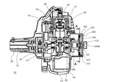
- FIG. 1 shows a configuration of a power unit 30 used here.
- This power unit 30 is used instead of the power unit 330 in FIG.
- FIG. 1 is a cross-sectional view along the crankshaft of the engine 40
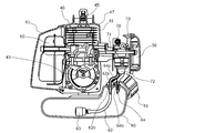
- FIG. 2 is a perspective view seen from the front side (left side in FIG. 1).
- the engine 40 used here is a two-cycle air-cooled engine, and is the same as ordinarily known except for the mechanism related to its starting.
- the reciprocating motion of the piston 42 in the cylinder 41 in the vertical direction is converted into the rotational motion of the crankshaft 43 and output.
- the rotational movement of the crankshaft 43 is transmitted to the transmission shaft 21 in the operating rod 20 via the centrifugal clutch 44.
- an ignition plug 45 for igniting the compressed air-fuel mixture introduced into the combustion chamber formed on the upper side of the piston 42 is mounted, and the ignition plug 45 is plugged with a plug cap 46 for energizing the ignition plug 45.
- This current is generated by boosting the current generated by a generator (not shown) with the rotation of the crankshaft 43 by an ignition coil (not shown), and flows to the spark plug 45 at an appropriate timing.
- the cylinder 41 is covered with an upper cover 47 from the upper side, and cooling air generated by a cooling fan (not shown) fixed to the crankshaft 43 flows through the inside covered with the upper cover 47.
- the cylinder 41 is cooled (air cooled). *
- a carburetor 70 is connected to a cylinder 41 via an insulator 71 at an intake port provided on the left side (right side in FIG. 2) of the engine 40. Air is introduced into the vaporizer 70 through an air cleaner 50 mounted on the left side thereof.
- a fuel tank 60 is provided below the engine 40, and an operator can remove the tank cap 61 and supply fuel (mixed fuel of gasoline and two-cycle oil) into the tank. Fuel is supplied to the carburetor 70 through a fuel pipe 62 from a fuel filter 63 provided at the tip of a fuel pipe 62 in the fuel tank 60.
- a box-like muffler 80 is attached to an exhaust port provided on the right side (left side in FIG. 2) of the engine 40, and the exhaust gas passes through the muffler 80 and is discharged into the atmosphere.
- a plurality of expansion chambers are provided in the muffler 80, and since a catalyst is provided in these chambers, exhaust gas is purified and exhaust noise is also reduced.
- a muffler 80 that is hot during operation is also covered with a muffler cover 81.
- a priming pump 72 that is manually operated is attached to the vaporizer 70. By operating (pushing) the priming pump 72 by the operator, pressure toward the carburetor 70 can be generated, and fuel can be guided from the fuel tank 60 to the carburetor 70 via the fuel pipe 62.
- the priming pump 72 has a hemispherical shape made of a transparent resin material, and it can be visually confirmed that fuel is present therein.
- the concentration of the air-fuel mixture generated by the carburetor 70 is determined by the setting of the carburetor 70, and this setting is performed so that the output of the engine 40 can be efficiently exhibited during operation. Optimized.
- a choke lever 73 is provided in the vaporizer 70. When the choke lever 73 is turned on (pulled), the air-fuel mixture concentration can be increased by narrowing the air passage.
- the operator can start the engine 40 with the choke lever 73 pulled at the time of starting, and when the engine 40 starts, the engine 40 can be put into an operating state by returning the choke lever 73.
- the fuel is first guided to the carburetor 70 using the priming pump 72, and the crankshaft 43 is forcibly rotated with the choke lever 73 pulled. It is necessary to make it.
- FIG. 3 is a diagram showing a cross-sectional view in the AA direction of FIG.
- FIG. 3A shows an initial state
- FIG. 3B shows an accumulated state
- FIG. 3C shows a state where the accumulated force is released and the crankshaft 43 is rotated. It is shown. *
- a mainspring case 102 is rotatably provided inside the case 101 with a mainspring spring 103 accommodated therein.
- the mainspring case 102 is connected to a power storage shaft 104 provided at the rear (right side in FIG. 1). Further, the spiral spring 103 is wound as shown in FIG.
- a central shaft 105 is provided at the center of the mainspring case 102, and the central shaft 105 is connected to a one-way clutch 106 provided on the front side (left side in FIG. 1).
- the one-way clutch 106 transmits rotation from the central shaft 105 to the crankshaft 43 during normal rotation (rotation in the direction in which the crankshaft 43 rotates during normal operation), but from the crankshaft 43 to the central shaft 105 side. Does not transmit rotation. For this reason, when the crankshaft 43 is stopped, if the center shaft 105 is rotated forward, the crankshaft 43 can be driven (rotated), and the engine 40 can be started. On the other hand, when the central shaft 105 stops after starting, the central shaft 105 is not affected by the rotation of the crankshaft 43 even if the crankshaft 43 rotates.
- the mainspring 103 is mounted in the mainspring case 102 so as to wind the central shaft 105.
- the inner end of the spring spring 103 is fixed to the central shaft 105, and the outer end thereof is fixed to the inner surface of the spring case 102.
- a claw 107 is provided on the outer surface of the mainspring case 102, and the claw 107 fixes the end of the mainspring spring 103 to prevent the mainspring spring 103 from falling off the mainspring case 102.
- the mainspring case 102 is press-fitted into the power storage shaft 104, and the mainspring case 102 can be driven by driving the power storage shaft 104.
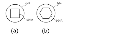
- an engaging portion 104A capable of engaging with an external rotating shaft is provided so that it can be rotated from the outside.
- the shape of the end face of the energy storage shaft 104 viewed from the rear side (right side in FIG. 1) is a rectangular recess at the rear end of the energy storage shaft 104.
- the engaged portion 104A is formed.
- the force accumulation shaft 104 can be rotated forward by engaging the engaging portion 104A with a rotating shaft having a convex portion having the same shape as that of the engaging portion 104A.
- the power storage shaft 104 (the mainspring case 102) can be rotated in the forward direction to store the mainspring spring 103 in the state shown in FIG.
- the shape of the engaging portion 104A is arbitrary as long as such an operation is possible.
- the engaging portion 104A has a hexagonal shape, a spline shaft or diagonally It is sufficient that the two surfaces are non-circular in which a concave portion is formed and power can be transmitted.
- the engaging portion 104A of the accumulator shaft 104 is formed as a convex portion, it may be formed as a concave portion and rotated by the convex portion.
- the mainspring 105 rotates the central shaft 105 and the crankshaft 43.
- the force stored in the mainspring spring 103 is released at once, so that the crankshaft 43 can be rotated with a strong force so that the piston 42 reciprocates a plurality of times. .
- the engine 40 is started.
- the crankshaft 43 rotates spontaneously, the rotation of the crankshaft 43 is suppressed from being transmitted to the central shaft 105 due to the presence of the one-way clutch 106.
- the accumulator shaft 104 is not affected by the rotation of the crankshaft 43. That is, the one-way clutch 106 does not affect the rear side of the center shaft 105 after the engine 40 is started.
- the engine 40 can be easily started by rotating the accumulator shaft 104 (engagement unit 104A) from outside.
- the accumulator type drive unit 100 includes the lightweight one-way clutch 106, the mainspring spring 103, and the like, so that the accumulator type drive unit 100 can be reduced in weight. For this reason, the whole brush cutter can be made lightweight.
- a starting device that rotates the accumulator shaft 104 via the engaging portion 104A a device that can be attached to the accumulator shaft 104 only when the engine 40 is started can be used as a separate body from the brush cutter.
- Any starting device may be used as long as it includes a rotating shaft that can be engaged with the engaging portion 104A and a starting mechanism that drives the rotating shaft.
- manual, electric, or high-pressure air can be used.
- manual operation that does not require connection with facility power or electric power that uses a battery as a power source is particularly preferable.
- FIG. 5 is a diagram showing a configuration when the manual starter 200 is used.
- a commonly known recoil starter for example, a device that drives a rotating shaft with a structure described in JP 2012-140904 A can be used.
- the front end (left end in FIG. 5) of the rotating shaft 201 has a quadrangular shape when viewed in the axial direction so as to engage with the engaging portion 104A.
- a reel 203 around which a rope 202 is wound is used, and the reel 203 is rotated forward by pulling out the rope 202 from the reel 203.
- the pulley 204 in front of the reel 203 also rotates in the forward direction, and the rotating shaft 201 fixed to the pulley 204 rotates.
- the rope drawn out by the spring 205 is rewound onto the reel 203.
- the reverse rotation when the rope is rewound is not transmitted to the pulley 204 side by the ratchet mechanism.
- the reel 203, the pulley 204, and the like are covered with a cover 206, and the rope 202 is pulled out from the cover 206.
- the rotating shaft 201 can be rotated in the forward direction by repeatedly performing an operation of pulling the rope 202 while the rotating shaft 201 is engaged with the engaging portion 104A.
- the crankshaft 43 can be driven after the mainspring 103 is sufficiently stored.
- the torque at which the crankshaft 43 is driven at this time can be sufficiently larger than the torque that the operator rotates the reel 203 by the rope 202.
- the engine 40 can be started more easily than when the engine is started using a normal recoil starter.
- the cover 206 and the case 101 can be fixed so that the cover 206 of the starting device 200 can be fixed to the case 101 of the accumulator type drive unit 100 with the rotating shaft 201 engaged with the engaging portion 104A. It is preferable to provide a concave portion on one side and a convex portion engaging with this on the other side.
- the configuration on the left side of FIG. 5 can be obtained only when the engine 40 is started, and after starting, the starting device 200 can be removed and the brush cutter can be used. Since the starter 200 is mounted when the engine 40 is started, the whole becomes heavy. However, the start work is performed in a state where the brush cutter is placed on the ground or the like, so that the weight is not a problem. In addition, since the accumulating drive unit 100 is used, the engine 40 can be started particularly easily, and the engine 40 can be easily started by a single operation in which the accumulating force in the mainspring spring 103 is released. On the other hand, since the starter 200 is not mounted during work, the brush cutter (engine 40) can be made lighter.
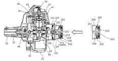
- FIG. 6 shows a form in the case of using the starting device 210 as in FIG.
- the major components in the starting mechanism 210 are a DC motor 212 that drives the rotating shaft 211 and a storage battery 213 that is a power source thereof.
- the DC motor 212 is housed in the motor case 214 and the storage battery 213 is housed in the storage battery case 215. .
- the motor case 214 and the storage battery case 215 are adjacent to each other in the direction perpendicular to the rotation shaft 211 in order to shorten the overall length.
- the current from the storage battery 213 flows through the DC motor 212 after being controlled by the control circuit 217 via the terminal 216.
- This on / off can be controlled by a switch (not shown) provided on the surface of the motor case 214 or the storage battery case 215.
- a pinion gear 218 is fixed to the output shaft of the DC motor 212, and the rotation of the pinion gear 218 is transmitted to the spindle 220 through the planetary gear mechanism 219 at a reduction ratio appropriate for starting.
- the rotating shaft 211 is fixed to the spindle 220. Since the current flowing through the DC motor 212 is appropriately controlled by the control circuit 217, it is possible to prevent the DC motor 212 and the like from being burned when overloaded. *
- the starter 210 can also be used in the same manner as the manual starter 200 described above. That is, the engine 40 can be easily started by engaging the rotating shaft 211 with the engaging portion 104A and turning on the switch. At this time, it is preferable that the motor case 214 can be engaged with the case 101. Since the DC motor 212 and the storage battery 213 are provided, the starter 210 is heavier than the manual starter 200. However, since the starter 210 is unnecessary during the operation, the starter 210 is removed, The brush cutter can be made lightweight.
- FIG. 7A shows a configuration in the case of using a starter 230 that is a modification of the electric starter 210.
- the motor case 214 and the storage battery case 215 are arranged in a direction perpendicular to the longitudinal direction (the direction of the rotating shaft 211) in order to shorten the overall length.
- the motor case 231 and the storage battery case 232 are connected in the longitudinal direction.
- the switch 234 is provided on the surface of the motor case 231, it is easy to operate the switch 234 while engaging the rotating shaft 233 with the engaging portion 104A.
- FIGS. 8A and 8B show the configuration in this case as in FIGS. 7A and 7B.
- the mainspring case 102, the mainspring spring 103, the central shaft 105, and the one-way clutch 106 are used in the same manner as the accumulator type drive unit 100, and the one-way clutch 106 and the crankshaft. The same applies to the connection with the terminal 43.
- the accumulator shaft 111 used here is not provided on the extension line of the crankshaft 43 but is provided above the crankshaft 43.
- the accumulator shaft 111 drives the mainspring case 102 via a mainspring case drive gear 112 fixed to the accumulator shaft 111.
- the rear end portion of the accumulator shaft 111 becomes the engaging portion 111A as in the case described above.
- the case 113 is larger in the vertical direction than the case 101 in order to cover the entire configuration. In this case, the direction in which the energy storage shaft 111 (rotary shaft 233) is rotated is the direction opposite to the forward direction of the crankshaft 43.
- the engine 40 in the brush cutter is started in a state where the brush cutter is placed on the ground. Further, as shown in FIG. 1 and the like, the crankshaft 43 is generally provided below the engine 40. For this reason, at the time of start-up, the crankshaft 43 is usually located at a location close to the ground. In such a case, as shown in FIG. 8, the operation of the starting device 230 becomes particularly easy by making the accumulator shaft 111 higher than the crankshaft 43. In particular, it becomes easy to use the elongated starting device 230 in a bent state. It is obvious that the manual starter 200 can be used in this form.
- the energy storage shaft may be configured to have an angle with respect to the crankshaft, and the engaging portion of the energy storage shaft may be positioned higher than the crankshaft. If the operability is not taken into consideration, the starter 230 can be started even when the accumulator shaft is on the extension line of the crankshaft 43. *
- FIG. 9 is a side view showing the configuration of such a brush cutter 400.
- FIG. 9A shows a form when the starting device 230 is attached
- FIG. 9B shows a form when it is not attached.
- the description of the cutting blade 11 is omitted in FIGS. 9A and 9B, and the description of the handle 13 is further omitted in FIG. 9B.
- the starting device 230 can be fixed along the operating rod 20 using the starting device fixing tool 22 provided near the center of the operating rod 20. At this time, if the elongated starting device 230 is attached to the antinode portion of the natural vibration mode of the operating rod 20 (the portion where the amplitude of vibration is large: the center portion in FIG. 9), the overall weight of the brush cutter 400 is increased. In addition, the starter 230 serves as a weight, so that vibration and deformation of the operation rod 20 can be suppressed. Further, it is possible to prevent the starter 230 from being lost when not in use. *
- the motor case and the storage battery case can be separated, only one of them, for example, only the motor case can be mounted.
- a storage battery case that can also be used as a power source for other work equipment is used, such a configuration is particularly preferable, and the weight of the portion attached to the brush cutter can be reduced. In this way, only a part of the starting device can be attached to the brush cutter.
- the parts to be mounted are small and light, the degree of freedom of the mounting position on the operating rod is increased. Further, other than the operating rod, for example, this is mounted in the gap between the fuel tank and the protective cover. You can also *
- the manual starter 200 and the electric starters 210 and 230 can be used as the starter, but the tip portion of the rotating shaft in these can be engaged with the engaging portion.
- which starting device is used is arbitrary.
- the electric starter 210 or 230 is usually used which is particularly easy to work, and the manual starter 200 is used as an emergency in the case where it is difficult to rotate the motor because the remaining amount of the storage battery is exhausted. Can also be used. *
- the engine working machine is a brush cutter.
- the above configuration is also effective in a working machine in which the engine is similarly used, such as a chain saw or a cultivator.
- the configuration of the engine is arbitrary, and the above configuration is effective even in a 4-cycle engine.
Landscapes
- Engineering & Computer Science (AREA)
- Chemical & Material Sciences (AREA)
- Combustion & Propulsion (AREA)
- Mechanical Engineering (AREA)
- General Engineering & Computer Science (AREA)
- Life Sciences & Earth Sciences (AREA)
- Environmental Sciences (AREA)
- Harvester Elements (AREA)
Abstract
エンジンの始動を容易に行うことができ、かつ軽量なエンジン作業機を得る。回転軸201を係合部104Aに係合させた状態で、作業者がロープ202を引く動作を繰り返し行うことによって、回転軸201を正方向に回転させることができる。これによって、蓄力軸104を駆動し、蓄力式駆動部100におけるゼンマイバネ103に蓄力をすることができる。その後、ゼンマイバネ103が充分蓄力された後に、クランク軸43を駆動することができる。この際、ゼンマイバネ103に蓄力がされるために、この際にクランク軸43が駆動されるトルクは、作業者がロープ202によってリール203を回転させるトルクよりも充分に大きくすることができる。
Description
本発明は、小型のエンジンが用いられるエンジン作業機、例えば刈払機等の構造に関する。
刈払機、送風機、チェーンソー、パワーカッタ等、作業者が携帯して使用する携帯用作業機や、発電機には、動力源として小型のエンジンが用いられる。
こうした刈払機の形状の一例を図10に示す。図10(a)は、この刈払機310の形態を示す側面図であり、図10(b)は、その後端部側に設けられた動力部を拡大した部分断面図である。図10(a)は、この刈払機310が地上に設置された際の形態を示しており、以下においては、上下方向とはこの場合における上下方向を意味し、この図における左側を前方、右側を後方とする。
この刈払機310においては、前後方向に細長い操作棹20の後端(一端)側には、刈刃11を駆動するための動力部330が設けられ、先端(他端)側に、回転する刈刃11が設けられる。動力部330における動力源としては、小型かつ軽量の2サイクル空冷式のエンジン340が用いられる。操作棹20の内部には、操作棹20と同軸とされエンジン340のクランク軸と遠心クラッチ(共に図示せず)によって接続された伝達軸(図示せず)が設けられる。クランク軸の回転速度が高まり遠心クラッチが接続された際には、この伝達軸はエンジン340によって回転運動をする。この回転運動が、操作棹20の先端に設置されたギヤケース12に伝達され、適切な減速比で刈刃11を回転させる。刈刃11の下側には、刈り取られた草木が作業者側に飛散することを抑制するための飛散防御カバー14が設けられる。操作棹20における前後方向の中央付近には、作業者が把持するためのハンドル13が左右に(図10(a)における紙面垂直方向に2つ)それぞれ設けられている。
動力部330において、エンジン340の左右(図10(a)における紙面手前側と向こう側)には、それぞれ吸気口、排気口が設けられ、吸気口側には気化器(図示せず)及びエアクリーナ50が、排気口側にはマフラ(図示せず)がそれぞれ接続されている。
気化器には、エアクリーナ50を介して空気が導入されると同時に、燃料(混合ガソリン)も供給され、これによって混合気が生成され、エンジン340に供給される。燃料は、エンジン340の下部に固定された燃料タンク60内に溜められ、燃料タンク60からチューブを介して気化器に導かれる。作業者は、燃料タンク60に設けられたタンクキャップ61を取り外し、燃料タンク60内に燃料を供給することができる。エンジン340の運転時には、吸気の際に発生する負圧によって燃料が燃料タンク60側から気化器側に吸い上げられる。燃料タンク60の下には、刈払機30が地面に設置される際にこれを支持すると共に、燃料タンク60の下側を覆う、樹脂材料で構成された保護カバー(スタンド)15が装着される。
この刈払機310を使用するに際しては、まず、エンジン340を始動する必要がある。始動のためには、気化器まで燃料を供給した状態で、停止しているエンジン340のクランク軸を強制的に回転させる必要がある。このため、特許文献1に記載されるように、クランク軸を手動で回転させることによってエンジン340を始動させる手動式のスタータ(リコイルスタータ)341が設けられている。スタータ341においては、ワンウェイクラッチを介してクランク軸に接続されたリールにロープが接続され、このロープを作業者が強く引くことによって、エンジン340内部におけるピストンの圧縮の際の圧力に逆らって強制的にクランク軸を回転させることができる。また、ロープが引かれた後では、バネによって自動的にロープはリール側に巻き戻される構成とされる。このため、こうした1回の操作でエンジン340が始動しない場合でも、作業者は、エンジン340が始動するまでロープを引く操作を繰り返し行うことができる。
また、エンジン340の温度が高い状態(停止後間もない状態)と比べて、一般的に冷間時にはエンジン340の始動は容易ではない。こうした場合には、始動時のみエンジン340に供給される混合気の燃料濃度を一時的に通常運転時よりも高めた方が始動は容易となる。このため、気化器には、その操作によって一時的に混合気を濃くするチョークレバーも設けられる。この場合、始動の際には、チョークレバーを操作(オンして混合気を濃くした状態でスタータ341を操作してエンジン340を始動し、エンジン340が始動した後でチョークレバーの動作を解除(オフ)して混合気を通常の濃度として、エンジン341を運転することができる。
上記の構成のスタータ341は非常に単純な構成であるために軽量であり、スタータ341が用いられたとしても、これが刈払機310全体の中で占める重量はわずかであり、刈払機310全体を軽量とすることができる。また、チョークレバーも、通常の気化器において装備されており、チョークレバーに関わる機構が全体に占める重量もわずかである。このため、上記の構成の刈払機310を軽量とすることができる。また、上記のとおり、スタータ341の操作は非常に単純であるため、これを用いてエンジン340を容易に始動することができ、刈払機310を用いた作業を行うことができる。
しかしながら、刈払機が使用される環境(例えば気温、湿度等)は様々であり、環境に応じてエンジンを始動させるために最適な条件は変化する。この際、上記の構成によってエンジンを始動する際に、チョークレバーをオンする操作、あるいはこれをオフする操作が適切に行われない場合もあった。例えば、上記のとおり、気温が低くエンジンの温度も低い場合にはチョークレバーをオンすることによって混合気を充分に濃くすることが有効であるが、エンジン停止後間もないためにエンジンの温度が高くなっている場合には、チョークレバーを操作しない(オフする)場合の方がエンジンの始動は容易である。こうした場合には、チョークレバーをオンすることによってむしろ始動は困難となる。こうしたチョークレバーの操作の判断は作業者によってその都度なされるため、操作が適正に行われなかったために始動が困難となった場合もあった。また、厳寒時には、チョークレバーをオンした場合でもエンジンの始動は容易ではなかった。
このように始動が困難となった場合には、スタータの1回の操作ではエンジンは始動せず、始動するまで作業者はスタータを繰り返し操作する必要があり、作業者にとってはエンジンの始動が大きな負担となった。こうした問題は、特に作業者の腕力が弱い場合においては、顕著となった。
こうした問題を解消するためには、刈払機において使用されるエンジンにおいても、自動車等に搭載されるエンジンのように、モータ(セルモータ)によって強制的にクランク軸を連続的に回転させるセルスタータを装着することが有効である。しかしながら、この場合には、セルスタータに加え、その電源となる電池も必要になるため、これらが装着されたエンジン全体の重量は大きく増加する。こうした状況は、作業者が携帯して使用する刈払機等にとって好ましくないことは明らかであるため、従来は、刈払機等にはセルスタータの使用は一般的ではなかった。
すなわち、エンジンの始動を容易に行うことができ、かつ軽量なエンジン作業機を得ることは困難であった。とは困難であった。
本発明は、かかる問題点に鑑みてなされたものであり、上記の問題点を解決する発明を提供することを目的とする。
本発明は、上記課題を解決すべく、以下に掲げる構成とした。本発明のエンジン作業機は、エンジンが搭載されるエンジン作業機であって、蓄力されたゼンマイバネによって前記エンジンのクランク軸にワンウェイクラッチを介して回転させる蓄力式駆動部を具備し、蓄力軸を回転させることによって前記ゼンマイバネが蓄力される構成とされ、外部の回転軸が着脱可能とされた係合部が前記蓄力軸に設けられたことを特徴とする。本発明のエンジン作業機において、前記係合部は、前記蓄力軸の端部に形成された非円形状部であることを特徴とする。本発明のエンジン作業機において、前記係合部は、前記エンジン作業機の載置時において前記クランク軸よりも上方に設けられたことを特徴とする。本発明のエンジン作業機は、前記エンジンがその一端側に固定された操作棹と、当該操作棹に装着され作業者に把持されるハンドルと、前記ハンドルを挟んで前記操作棹の他端側に設けられ、前記エンジンによって駆動される刈刃と、を具備する刈払機であることを特徴とする。本発明のエンジン作業機は、前記係合部が含まれる領域に着脱可能とされ、前記回転軸と前記回転軸を回転させる始動機構とが設けられた始動装置を具備することを特徴とする。本発明のエンジン作業機は、前記係合部が含まれる領域に着脱可能とされ、前記回転軸と前記回転軸を回転させる始動機構とが設けられた始動装置を具備し、前記係合部が含まれる領域に装着されない状態の前記始動装置又は前記始動装置を構成する一部を前記操作棹に固定する始動装置固定具が前記操作棹に設けられたことを特徴とする。本発明のエンジン作業機は、モータによって前記回転軸を駆動する前記始動機構が用いられた前記始動装置を具備することを特徴とする。本発明のエンジン作業機は、手動によって前記回転軸を駆動する前記駆動機構が用いられた前記始動装置を具備することを特徴とする。本発明のエンジン作業機は、モータによって前記回転軸を駆動する前記始動機構が用いられた前記始動装置と、手動によって前記回転軸を駆動する前記始動機構が用いられた前記始動装置とが、相互に切り替え可能に前記係合部が含まれる領域に装着可能とされたことを特徴とする。
本発明は以上のように構成されているので、エンジンの始動を容易に行うことができ、かつ軽量なエンジン作業機を得ることができる。
本発明の実施の形態となるエンジン作業機(刈払機)の構成について説明する。ここでは、小型のエンジンが使用され、このエンジンを始動させるための機構に特徴を有する。このエンジン作業機においては、エンジンの始動のために、蓄力式の駆動機構が用いられる。蓄力式の駆動機構においては、蓄力軸を回転させることによって、ゼンマイバネに蓄力がなされる。ゼンマイバネに充分蓄力がなされた後で、ゼンマイバネの反力によってエンジンのクランク軸が駆動されることによって、エンジンが始動する。この際、ゼンマイバネに蓄力されるために、大きなトルクがクランク軸に加わり、エンジンの始動を容易に行うことができる。
ここで、この駆動機構においては、蓄力軸を外部から回転させることができる構成とされている。このため、蓄力軸を回転させるための機構(始動装置)をエンジンに固定する必要はないため、刈払機自身を軽量化することができる。また、始動装置が着脱可能であるために、複数の種類の始動装置を適宜選択して用いることができる。
図1は、ここで用いられる動力部30の構成を示す、この動力部30は、図10における動力部330に代わりに用いられる。図1は、エンジン40のクランク軸に沿った断面図であり、図2は、前方側(図1における左側)から見たその透視図である。ここで用いられるエンジン40は、2サイクルの空冷エンジンであり、その始動に関わる機構以外については、通常知られるものと同様である。
このエンジン40においては、シリンダ41中におけるピストン42の上下方向の往復運動がクランク軸43の回転運動に変換されて出力される。クランク軸43の回転運動は、遠心クラッチ44を介して操作棹20中の伝達軸21に伝達される。シリンダ41の上側には、ピストン42の上側に形成された燃焼室に導入され圧縮された混合気を点火する点火プラグ45が装着され、点火プラグ45にはこれに通電をするためのプラグキャップ46が装着される。この電流は、クランク軸43の回転に伴ってジェネレータ(図示せず)で発生した電流がイグニッションコイル(図示せず)で昇圧されることによって生成され、適正なタイミングで点火プラグ45に流れる。シリンダ41は、上側から上部カバー47で覆われており、クランク軸43に固定された冷却ファン(図示せず)によって生成された冷却風が、上部カバー47で覆われた内部を流れることによって、シリンダ41が冷却(空冷)される。
図2に示されるように、エンジン40の左側(図2における右側)に設けられた吸気口には、気化器70が、インシュレータ71を介してシリンダ41に接続されている。気化器70には、その左側に装着されたエアクリーナ50を通して空気が導入される。また、エンジン40の下側には、燃料タンク60が設けられ、作業者はタンクキャップ61を取り外してこの中に燃料(ガソリンと2サイクル用オイルの混合燃料)を供給することができる。気化器70には、燃料タンク60内の燃料パイプ62の先端に設けられた燃料フィルタ63から燃料パイプ62を介して燃料が供給される。エンジン40の運転中においては、ピストン42の上下運動(クランク軸43の回転運動)に伴って発生した負圧によって、エアクリーナ50から気化器70に空気が吸入され、この流れによって燃料も気化器70に吸い上げられ、空気と燃料との混合気が生成されてシリンダ41内の燃焼室に導入される。
また、エンジン40の右側(図2における左側)に設けられた排気口には、箱状のマフラ80が装着され、排気ガスはマフラ80を通ってから大気中に排出される。マフラ80中には複数の膨張室が設けられ、これらの内部には触媒が設けられているために、排気ガスの浄化が行われ、かつ排気音の低減も行われる。運転時に高温となるマフラ80も、マフラカバー81で覆われている。
エンジン40の始動後(運転時)には、燃料は負圧によって気化器70側に吸い上げられるものの、始動時(運転前)において気化器70内に燃料が存在しない場合には、まず、燃料を気化器70側に導く必要がある。このため、気化器70には、手動で動作するプライミングポンプ72が装着されている。作業者がプライミングポンプ72を操作する(押す)ことによって、気化器70側に向かう圧力を発生させ、燃料タンク60側から燃料パイプ62を経由して気化器70側に燃料を導くことができる。プライミングポンプ72は透明の樹脂材料で構成された半球状であり、この中に燃料があることを目視で確認することができる。また、気化器70内に燃料が溜められた後、余分な燃料はリターンパイプ64を介して再び燃料タンク60内に送られる。燃料タンク60は半透明の樹脂材料で構成されるため、燃料がリターンパイプ64から燃料タンク60に戻る状況も目視で確認することができる。燃料パイプ62とリターンパイプ64は、それぞれ燃料タンク60上部に設けられた貫通孔62a、64aを貫通し、貫通孔62aと燃料パイプ62の間、貫通孔64aとリターンパイプ64の間は、ゴムブッシュ62b、64bで密封されている。
また、気化器70で生成される混合気の濃度(空気に対する燃料の比率)は、気化器70の設定で定まり、この設定は、運転時において効率的にエンジン40の出力が発揮されるように最適化される。しかしながら、一般には、エンジン40の温度が低い場合(冷間時)の始動時には、混合気の濃度は、運転時の濃度よりも高くした方が、エンジン40を容易に始動することができる。このため、気化器70においては、チョークレバー73が設けられる。チョークレバー73がオンされた(引かれた)場合においては、空気の通路を狭窄させることによって混合気の濃度を高めることができる。このため、作業者は、始動時にチョークレバー73を引いた状態でエンジン40を始動し、エンジン40が始動したら、チョークレバー73を戻すことによって、エンジン40を運転状態とすることができる。このため、冷間時にエンジン40を始動させるためには、通常は、まずプライミングポンプ72を用いて燃料を気化器70まで導き、チョークレバー73を引いた状態で、クランク軸43を強制的に回転させることが必要となる。
上記の動力部30においては、クランク軸43を強制的に回転させるために、クランク軸43の後方(図1における右方)に、蓄力されたゼンマイバネによってクランク軸43を回転させる蓄力式駆動部100が設けられている。図3は、蓄力式駆動部100の図1におけるA-A方向の断面図を蓄力の状況に応じて示した図である。ここで、図3(a)においては初期状態、図3(b)においては蓄力された状態、図3(c)においては蓄力が開放されクランク軸43を回転させる際の状態、がそれぞれ示されている。
蓄力式駆動部100においては、ケース101の内部に、ゼンマイケース102が内部にゼンマイバネ103を収容した状態で回転可能に設けられる。ゼンマイケース102は、後方(図1における右側)に設けられた蓄力軸104と接続される。また、ゼンマイバネ103が図3(b)に示されるように巻かれることによって蓄力がなされる。一方、ゼンマイケース102の中央には中心軸105が設けられ、中心軸105は、前方(図1における左側)に設けられたワンウェイクラッチ106と接続される。ワンウェイクラッチ106は、正回転(通常運転時におけるクランク軸43が回転する方向の回転)時においては、中心軸105からクランク軸43へ回転を伝達するが、クランク軸43から中心軸105側へは回転を伝達しない。このため、クランク軸43が停止している場合に、中心軸105を正回転させれば、クランク軸43を駆動(回転)させることができ、エンジン40を始動させることができる。一方、始動後に中心軸105が停止した場合、クランク軸43が回転しても中心軸105はクランク軸43の回転の影響を受けない。
図3に示されるように、ゼンマイバネ103は、中心軸105を巻回する形態でゼンマイケース102内に装着される。ゼンマイバネ103の内側端部は中心軸105に固定され、その外側端部はゼンマイケース102の内面に固定される。また、ゼンマイケース102の外面には、爪107が設けられ、この爪107は、ゼンマイバネ103の端部を固定しており、ゼンマイバネ103がゼンマイケース102から脱落することを防止している。また、ゼンマイケース102は蓄力軸104に圧入されており、蓄力軸104が駆動することでゼンマイケース102も駆動することができる。一方、中心軸105とゼンマイケース102は分離した構造になっており、ゼンマイケース102からの駆動力はゼンマイバネ103を介して中心軸105に伝達されることになる。このため、クランク軸43が固定された場合には、蓄力軸104を回転させることによって、図3(b)に示されるようにゼンマイバネ103を巻き、蓄力をすることができる。
ここで、蓄力軸104の後端には、外部からこれを回転させることができるように、外部の回転軸を係合させることのできる係合部104Aが設けられている。具体的には、後方側(図1における右側)から見た蓄力軸104の端面の形状を図4(a)に示すように、蓄力軸104の後端部には、四角形の凹部とされた係合部104Aが形成されている。係合部104Aと同様の形状を具備する凸部を先端に具備する回転軸を係合部104Aに係合させることによって、蓄力軸104を正回転させることができる。このため、中心軸105が固定された状態で、蓄力軸104(ゼンマイケース102)を正回転させ、ゼンマイバネ103に蓄力をした図3(b)の状態とすることができる。なお、係合部104Aの形状は、こうした動作が可能である限りにおいて任意であり、例えば図4(b)に示されるように、係合部104Aを六角形状としたり、スプライン軸や対角上の二面など、凹部が形成された非円形であり動力の伝達が可能であればよい。また、蓄力軸104の係合部104Aは凸部として形成したが、凹部として形成し、凸部により回転させるようにしてもよい。
ここで、前記の通り、ゼンマイケース102を正回転側に駆動した場合には、ゼンマイバネ103を介して連結された中心軸105も正回転側に駆動され、これによってクランク軸43も正回転側に駆動される。しかしながら、動作していない状態のエンジン40において、ピストン42が上死点に向かう圧縮行程においては燃焼室の圧力が高まり、この圧力に逆らえる力を加えない限り、クランク軸43を更に正回転させることはできない。このため、この圧力によって、クランク軸43及び中心軸105が回転することは抑制され、ゼンマイバネ103にこの圧力に逆らえる力が蓄力されるまでは中心軸105は固定され、蓄力軸104(ゼンマイケース102)の回転に伴って、図3(b)に示されるように蓄力がなされる。
その後、ゼンマイバネ103が充分蓄力され、ピストン42による圧縮の際の圧力に逆らうことのできる程度の力が蓄力されたら、ゼンマイバネ103によって、中心軸105及びクランク軸43が回転する。この際には、図3(c)に示されるようにゼンマイバネ103に蓄えられた力が一気に解放されるため、ピストン42が複数回往復するようにクランク軸43を強い力で回転させることができる。これによって、エンジン40が始動する。エンジン40が始動しクランク軸43が自発的に回転した後は、ワンウェイクラッチ106の存在によって、クランク軸43の回転が中心軸105側に伝達されることは抑制される。このため、蓄力軸104もクランク軸43の回転の影響を受けない。すなわち、ワンウェイクラッチ106によって、エンジン40の始動後には中心軸105よりも後方側はエンジン40の影響を受けることがない。
このため、上記の動力部30においては、蓄力軸104(係合部104A)を外部から正回転させることによって、エンジン40を容易に始動することができる。ここで、蓄力式駆動部100は、上記のとおり、軽量なワンウェイクラッチ106、ゼンマイバネ103等で構成されるため、蓄力式駆動部100を軽量とすることができる。このため、刈払機全体を軽量とすることができる。
一方、係合部104Aを介して蓄力軸104を回転させる始動装置は、刈払機とは別体として、エンジン40の始動時においてのみ蓄力軸104に装着可能なものを用いることができる。この始動装置としては、係合部104Aに係合可能な回転軸と、この回転軸を駆動する始動機構を具備するものであれば、任意のものを用いることができる。この始動方式としては、手動、電動、あるいは、高圧空気によるものを用いることができる。ただし、刈払機のように、主に屋外で使用されるエンジン作業機の場合には、設備用力との接続を要さない手動、あるいは電池を電源とした電動が特に好ましい。
図5は、手動の始動装置200が用いられる際の構成を示す図である。ここで用いられる始動装置200としては、通常知られるリコイルスタータ、例えば特開2012-140904号公報に記載の構造によって回転軸を駆動するものを用いることができる。図5の右側においては、始動装置200の回転軸201に沿った断面が示されている。回転軸201の前端(図5における左端)は、係合部104Aと係合するように、軸方向視において四角形状とされる。
この始動装置200においては、ロープ202が巻回されたリール203が用いられ、リール203からロープ202を引き出すことによって、リール203が正回転する。リール203が正回転した場合には、その前方にあるプーリ204も正回転し、プーリ204に固定された回転軸201が回転する。また、バネ205によって、引き出されたロープは、リール203に巻き戻されるが、この際には、ラチェット機構によって、巻き戻される際の逆回転はプーリ204側には伝達されない。リール203、プーリ204等はカバー206で覆われ、ロープ202はカバー206から外側に引き出されている。
このため、回転軸201を係合部104Aに係合させた状態で、作業者がロープ202を引く動作を繰り返し行うことによって、回転軸201を正方向に回転させることができる。これによって、蓄力軸104を駆動し、蓄力式駆動部100におけるゼンマイバネ103に蓄力をすることができる。その後、前記の通り、ゼンマイバネ103が充分蓄力された後に、クランク軸43を駆動することができる。この際、ゼンマイバネ103に蓄力がされるために、この際にクランク軸43が駆動されるトルクは、作業者がロープ202によってリール203を回転させるトルクよりも充分に大きくすることができる。このため、通常のリコイルスタータを用いてエンジンを始動する場合と比べて、容易にエンジン40を始動させることができる。
この構成においては、回転軸201を係合部104Aに係合させた状態で始動装置200のカバー206を蓄力式駆動部100のケース101に固定できるように、例えば、カバー206、ケース101の一方に凹部、他方にこれに係合する凸部を設けることが好ましい。
こうした始動装置200を用いることによって、エンジン40の始動時においてのみ図5左側の形態とし、始動した後には始動装置200を取り外し、刈払機を使用することができる。エンジン40の始動時には始動装置200が装着されるために全体は重くなるが、始動作業は刈払機を地面等に載置した状態で行われるために、その重量は問題とはならない。また、蓄力式駆動部100が用いられるために、エンジン40の始動は特に容易となり、ゼンマイバネ103における蓄力が開放される1回の動作によって容易にエンジン40を始動させることができる。一方、作業時には始動装置200は装着されないため、刈払機(エンジン40)を軽量とすることができる。
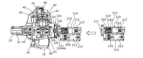
次に、電動式の始動機構を具備する始動装置を用いる場合について説明する。図6は、この始動装置210を使用する場合の形態を図5と同様に示す。始動機構210における大きな構成要素は、回転軸211を駆動するDCモータ212と、その電源となる蓄電池213であり、DCモータ212はモータケース214に、蓄電池213は蓄電池ケース215内に収容されている。始動装置210においては、全長を短くするために、モータケース214と蓄電池ケース215とが、回転軸211と垂直な方向において隣接している。蓄電池213からの電流は、ターミナル216を介して制御回路217で制御されてからDCモータ212に流れる。このオン・オフは、モータケース214又は蓄電池ケース215の表面に設けられたスイッチ(図示せず)で制御することができる。DCモータ212の出力軸にはピニオンギヤ218が固定され、ピニオンギヤ218の回転が遊星歯車機構219を介して始動に適正な減速比でスピンドル220に伝達される。回転軸211はスピンドル220に固定される。制御回路217によって、DCモータ212に流される電流が適正に制御されるため、過負荷時のDCモータ212等の焼損等を防止することができる。
この始動装置210も、前記の手動式の始動装置200と同様に用いることができる。すなわち、回転軸211を係合部104Aに係合させ、スイッチをオンすることにより、エンジン40を容易に始動させることができる。この際、モータケース214をケース101に係合させることができる構成とすることが好ましい。DCモータ212と蓄電池213を具備するために、この始動装置210は前記の手動式の始動装置200よりも重くなるが、やはり作業時には始動装置210は不要となるために、始動装置210を取り外し、刈払機を軽量とすることができる。
また、図7(a)に、電動式の始動装置210の変形例である始動装置230を用いた場合の構成を示す。前記の始動装置210においては、全長を短縮するために、モータケース214と蓄電池ケース215とが長手方向(回転軸211の方向)と垂直な方向において並んだ構成とされた。これに対し、この始動装置230においては、モータケース231と蓄電池ケース232とが長手方向で連結される。このため、始動装置230は前後方向で細長くなるものの、作業者がこれを把持しやすくなる。このため、この構成の場合には、モータケース231をケース101に係合させることなく、作業者がモータケース231を把持して回転軸233を係合部104Aに係合させることが容易となる。この際、モータケース231の表面にスイッチ234を設ければ、回転軸233を係合部104Aに係合させながら、このスイッチ234を操作することも容易である。
この始動装置230においては、前後方向の全長が長くなるために、取り扱いを容易とするため、図7(b)に示されるように蓄電池ケース232とモータケース231の間で屈曲が可能とすることが好ましい。蓄電池ケース232とモータケース231の間には電気配線は設けられるが、回転を伝達するための機械的構造物は存在しないため、ヒンジ構造等を用いて、こうした構成とすることは容易である。
また、こうした構成の始動装置230を用いる場合には、蓄力式駆動部をこれに対応した構成とすることにより、エンジン40の始動をより容易とすることもできる。図8(a)、(b)は、この場合における構成を図7(a)(b)と同様に示す。ここで用いられる蓄力式駆動部110においては、ゼンマイケース102、ゼンマイバネ103、中心軸105、ワンウェイクラッチ106については、前記の蓄力式駆動部100と同様に用いられ、ワンウェイクラッチ106とクランク軸43との間の接続も同様である。ただし、ここで用いられる蓄力軸111は、クランク軸43の延長線上には設けられず、クランク軸43よりも上側に設けられる。この蓄力軸111は、蓄力軸111に固定されたゼンマイケース駆動ギヤ112を介してゼンマイケース102を駆動する。蓄力軸111の後端部が係合部111Aとなることは前記の場合と同様である。ケース113は、これらの構成全体を覆うために、前記のケース101よりの上下方向に大きくなる。なお、この場合には、蓄力軸111(回転軸233)を回転させる方向は、クランク軸43の正方向と逆の方向となる。
一般に、刈払機におけるエンジン40の始動は、刈払機を地面に載置した状態で行われる。また、図1等に示されるように、一般にクランク軸43はエンジン40における下方に設けられる。このため、始動時においては、通常はクランク軸43は地面に近い箇所に位置する。こうした場合においては、図8に示されるように、蓄力軸111をクランク軸43よりも高くすることによって、始動装置230の操作が特に容易となる。特に、細長い始動装置230を屈曲させた状態での使用が容易となる。なお、この形態で手動式の始動装置200を用いることができることも明らかである。また、クランク軸に対して蓄力軸が角度を有して構成され、蓄力軸の係合部がクランク軸より高い位置にくるようにしてもよい。なお、操作性を考慮しなければ、蓄力軸がクランク軸43の延長線上にあっても、始動装置230を始動させることも可能である。
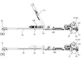
また、特に刈払機においては、こうした細長い始動装置230を、これを蓄力式駆動部に接続しない状態において、刈払機自身に装着することもできる。図9は、こうした刈払機400の構成を示す側面図であり、図9(a)は、始動装置230を装着した際の形態、図9(b)は装着しない場合の形態をそれぞれ示す。図9(a)(b)においては刈刃11の記載が、図9(b)においては更にハンドル13の記載が省略されている。
この構成においては、操作棹20の中央付近に設けられた始動装置固定具22を用いて始動装置230を操作棹20に沿って固定することができる。この際、操作棹20の固有振動モードにおける腹の部分(振動の振幅が大きくなる部分:図9においては中央部)に細長い始動装置230を装着すれば、刈払機400の全体重量は重くなるものの、始動装置230が錘の役目を果たすことで操作棹20の振動や変形を抑制することもできる。また、始動装置230を使用しない際にこれを紛失することも防止される。
図7、8に示されるように始動装置230をエンジン40の後端部に装着した状態では、刈払機の後端部が特に重くなるために、操作棹に装着されたハンドルを用いて刈払機を操作することが困難となり、作業性が悪くなる。これに対して、細長い始動装置230が操作棹20に沿って装着された図9の構成においては、始動装置230の重量が作業性に及ぼす悪影響は低減される。
また、例えば、モータケースと蓄電池ケースとが分離可能とされる場合には、これらのうちの一方のみ、例えばモータケースのみを装着できる構成とすることもできる。他の作業機器の電源としても使用可能な蓄電池ケースが用いられる場合には、こうした形態が特に好ましく、刈払機に装着される部分の重量を低減することができる。このように、始動装置の一部のみを刈払機に装着することもできる。また、特にこのように装着される部品が小さく軽量となる場合には、操作棹における装着位置の自由度が高くなり、更に、操作棹以外、例えば燃料タンクと保護カバーの隙間にこれを装着することもできる。
また、上記のように、始動装置としては、手動式の始動装置200、電動式の始動装置210、230を用いることができるが、これらにおける回転軸の先端部分が係合部と係合可能である限りにおいて、どの始動装置を用いるかは任意である。例えば、通常は作業が特に容易である電動式の始動装置210、230を用いる構成とし、蓄電池の残量がなくなりモータを回転させることが困難となった場合の非常用として手動式の始動装置200を用いることもできる。
上記の例においては、エンジン作業機が刈払機であるものとしたが、同様にエンジンが用いられる作業機、例えばチェーンソー、カルチベータ等においても、上記の構成が有効であることは明らかである。また、エンジンの構成は任意であり、4サイクルエンジンにおいても上記の構成は有効である。
11 刈刃
12 ギヤケース
13 ハンドル
14 飛散防御カバー
15 保護カバー(スタンド)
20 操作棹
21 伝達軸
22 始動装置固定具
30、330 動力部
40、340 エンジン
41 シリンダ
42 ピストン
43 クランク軸
44 遠心クラッチ
45 点火プラグ
46 プラグキャップ
47 上部カバー
50 エアクリーナ
60 燃料タンク
61 タンクキャップ
62 燃料パイプ
62a、64a 貫通孔
62b、64b ゴムブッシュ
63 燃料フィルタ
64 リターンパイプ
70 気化器
71 インシュレータ
72 プライミングポンプ
73 チョークレバー
80 マフラ
81 マフラカバー
100、110 蓄力式駆動部
101、113 ケース
102 ゼンマイケース
103 ゼンマイバネ
104、111 蓄力軸
104A、111A 係合部
105 中心軸
106 ワンウェイクラッチ
107 爪
200、210、230 始動装置
201、211、233 回転軸
202 ロープ
203 リール
204 プーリ
205 バネ
206 カバー
212 DCモータ
213 蓄電池
214、231 モータケース
215、232 蓄電池ケース
216 ターミナル
217 制御回路
218 ピニオンギヤ
219 遊星歯車機構
220 スピンドル
234 スイッチ
310、400 刈払機
341 スタータ(リコイルスタータ)
Claims (9)
- エンジンが搭載されるエンジン作業機であって、蓄力されたゼンマイバネによって前記エンジンのクランク軸をワンウェイクラッチを介して回転させる蓄力式駆動部を具備し、蓄力軸を回転させることによって前記ゼンマイバネが蓄力される構成とされ、外部の回転軸が着脱可能とされた係合部が前記蓄力軸に設けられたことを特徴とするエンジン作業機。
- 前記係合部は、前記蓄力軸の端部に形成された非円形状部であることを特徴とする請求項1に記載のエンジン作業機。
- 前記係合部は、前記エンジン作業機の載置時において前記クランク軸よりも上方に設けられたことを特徴とする請求項1又は2に記載のエンジン作業機。
- 前記エンジンがその一端側に固定された操作棹と、当該操作棹に装着され作業者に把持されるハンドルと、前記ハンドルを挟んで前記操作棹の他端側に設けられ、前記エンジンによって駆動される刈刃と、を具備する刈払機であることを特徴とする請求項1から請求項3までのいずれか1項に記載のエンジン作業機。
- 前記係合部が含まれる領域に着脱可能とされ、前記回転軸と前記回転軸を回転させる始動機構とが設けられた始動装置を具備することを特徴とする請求項1から請求項4までのいずれか1項に記載のエンジン作業機。
- 前記係合部が含まれる領域に着脱可能とされ、前記回転軸と前記回転軸を回転させる始動機構とが設けられた始動装置を具備し、前記係合部が含まれる領域に装着されない状態の前記始動装置又は前記始動装置を構成する一部を前記操作棹に固定する始動装置固定具が前記操作棹に設けられたことを特徴とする請求項4に記載のエンジン作業機。
- モータによって前記回転軸を駆動する前記始動機構が用いられた前記始動装置を具備することを特徴とする請求項5又は6に記載のエンジン作業機。
- 手動によって前記回転軸を駆動する前記駆動機構が用いられた前記始動装置を具備することを特徴とする請求項5又は6に記載のエンジン作業機。
- モータによって前記回転軸を駆動する前記始動機構が用いられた前記始動装置と、手動によって前記回転軸を駆動する前記始動機構が用いられた前記始動装置とが、相互に切り替え可能に前記係合部が含まれる領域に装着可能とされたことを特徴とする請求項5又は6に記載のエンジン作業機。
Applications Claiming Priority (2)
| Application Number | Priority Date | Filing Date | Title |
|---|---|---|---|
| JP2014039166A JP2015161296A (ja) | 2014-02-28 | 2014-02-28 | エンジン作業機 |
| JP2014-039166 | 2014-02-28 |
Publications (1)
| Publication Number | Publication Date |
|---|---|
| WO2015129357A1 true WO2015129357A1 (ja) | 2015-09-03 |
Family
ID=54008684
Family Applications (1)
| Application Number | Title | Priority Date | Filing Date |
|---|---|---|---|
| PCT/JP2015/051862 WO2015129357A1 (ja) | 2014-02-28 | 2015-01-23 | エンジン作業機 |
Country Status (2)
| Country | Link |
|---|---|
| JP (1) | JP2015161296A (ja) |
| WO (1) | WO2015129357A1 (ja) |
Cited By (4)
| Publication number | Priority date | Publication date | Assignee | Title |
|---|---|---|---|---|
| EP3147494A1 (en) * | 2015-09-22 | 2017-03-29 | Coza International Limited Hongkong | Dual source starter system for an engine |
| CN106677896A (zh) * | 2017-03-17 | 2017-05-17 | 重庆工业职业技术学院 | 一种燃油内燃机发电机组 |
| CN106888672A (zh) * | 2017-03-06 | 2017-06-27 | 李文新 | 一种用于市政园林工程的便携式割草机 |
| WO2018126327A1 (en) * | 2017-07-20 | 2018-07-12 | Budden Doyle | Method and apparatus for starting a small combustion engine |
Citations (4)
| Publication number | Priority date | Publication date | Assignee | Title |
|---|---|---|---|---|
| US1936555A (en) * | 1932-02-27 | 1933-11-21 | Eclipse Aviat Corp | Engine starting mechanism |
| JPS63138023U (ja) * | 1987-03-04 | 1988-09-12 | ||
| JPH0184528U (ja) * | 1987-11-27 | 1989-06-05 | ||
| JP2011043081A (ja) * | 2009-08-19 | 2011-03-03 | Makita Corp | 電動工具を用いて作業機のエンジンを始動するためのアタッチメント |
-
2014
- 2014-02-28 JP JP2014039166A patent/JP2015161296A/ja active Pending
-
2015
- 2015-01-23 WO PCT/JP2015/051862 patent/WO2015129357A1/ja active Application Filing
Patent Citations (4)
| Publication number | Priority date | Publication date | Assignee | Title |
|---|---|---|---|---|
| US1936555A (en) * | 1932-02-27 | 1933-11-21 | Eclipse Aviat Corp | Engine starting mechanism |
| JPS63138023U (ja) * | 1987-03-04 | 1988-09-12 | ||
| JPH0184528U (ja) * | 1987-11-27 | 1989-06-05 | ||
| JP2011043081A (ja) * | 2009-08-19 | 2011-03-03 | Makita Corp | 電動工具を用いて作業機のエンジンを始動するためのアタッチメント |
Cited By (5)
| Publication number | Priority date | Publication date | Assignee | Title |
|---|---|---|---|---|
| EP3147494A1 (en) * | 2015-09-22 | 2017-03-29 | Coza International Limited Hongkong | Dual source starter system for an engine |
| CN106888672A (zh) * | 2017-03-06 | 2017-06-27 | 李文新 | 一种用于市政园林工程的便携式割草机 |
| CN106677896A (zh) * | 2017-03-17 | 2017-05-17 | 重庆工业职业技术学院 | 一种燃油内燃机发电机组 |
| WO2018126327A1 (en) * | 2017-07-20 | 2018-07-12 | Budden Doyle | Method and apparatus for starting a small combustion engine |
| US10087905B2 (en) | 2017-07-20 | 2018-10-02 | Doyle Budden | Method and apparatus for starting a small combustion engine |
Also Published As
| Publication number | Publication date |
|---|---|
| JP2015161296A (ja) | 2015-09-07 |
Similar Documents
| Publication | Publication Date | Title |
|---|---|---|
| US7748360B2 (en) | Handheld electric starter for engines and method of use | |
| WO2015129357A1 (ja) | エンジン作業機 | |
| CN103443418B (zh) | 混合动力驱动型便携式工作机 | |
| US7530340B1 (en) | Removable linkage of a modified cordless power drill for gasoline engines to power-assist starting of gasoline engines | |
| US20140165946A1 (en) | Power tool | |
| JPH0649899Y2 (ja) | 自動始動器付携帯形作業機械用内燃機関 | |
| JP2006311828A (ja) | 刈払機 | |
| JP2011043081A (ja) | 電動工具を用いて作業機のエンジンを始動するためのアタッチメント | |
| JP2006336522A (ja) | 内燃エンジンの始動装置および始動方法 | |
| US5007173A (en) | Gasoline engine powered hand-held circular saw | |
| US20140083375A1 (en) | Power tool | |
| WO2013043092A1 (en) | A starter apparatus for starting an internal combustion engine | |
| JP6260140B2 (ja) | エンジン作業機 | |
| JP2009197770A (ja) | 作業機 | |
| EP3147494A1 (en) | Dual source starter system for an engine | |
| JP3813921B2 (ja) | 内燃エンジンの始動方法及び始動装置 | |
| JP2014066198A (ja) | 動力工具 | |
| JP2007046585A (ja) | 携帯型作業機 | |
| JP2014079240A (ja) | 動力工具 | |
| JP2014058901A (ja) | エンジン作業機 | |
| JP2011074856A (ja) | エンジン作業機 | |
| CN205552715U (zh) | 一种用于汽油链锯的启动装置 | |
| JP2010203246A (ja) | エンジン作業機 | |
| JP6090058B2 (ja) | エンジン作業機 | |
| RU41494U1 (ru) | Перфоратор |
Legal Events
| Date | Code | Title | Description |
|---|---|---|---|
| 121 | Ep: the epo has been informed by wipo that ep was designated in this application |
Ref document number: 15754578 Country of ref document: EP Kind code of ref document: A1 |
|
| NENP | Non-entry into the national phase |
Ref country code: DE |
|
| 122 | Ep: pct application non-entry in european phase |
Ref document number: 15754578 Country of ref document: EP Kind code of ref document: A1 |