WO2015129206A1 - 燃料電池モジュールおよび燃料電池スタック - Google Patents
燃料電池モジュールおよび燃料電池スタック Download PDFInfo
- Publication number
- WO2015129206A1 WO2015129206A1 PCT/JP2015/000749 JP2015000749W WO2015129206A1 WO 2015129206 A1 WO2015129206 A1 WO 2015129206A1 JP 2015000749 W JP2015000749 W JP 2015000749W WO 2015129206 A1 WO2015129206 A1 WO 2015129206A1
- Authority
- WO
- WIPO (PCT)
- Prior art keywords
- fuel cell
- layer
- cell layer
- interconnector
- anode
- Prior art date
- Legal status (The legal status is an assumption and is not a legal conclusion. Google has not performed a legal analysis and makes no representation as to the accuracy of the status listed.)
- Ceased
Links
Images
Classifications
-
- H—ELECTRICITY
- H01—ELECTRIC ELEMENTS
- H01M—PROCESSES OR MEANS, e.g. BATTERIES, FOR THE DIRECT CONVERSION OF CHEMICAL ENERGY INTO ELECTRICAL ENERGY
- H01M8/00—Fuel cells; Manufacture thereof
- H01M8/02—Details
- H01M8/0297—Arrangements for joining electrodes, reservoir layers, heat exchange units or bipolar separators to each other
-
- H—ELECTRICITY
- H01—ELECTRIC ELEMENTS
- H01M—PROCESSES OR MEANS, e.g. BATTERIES, FOR THE DIRECT CONVERSION OF CHEMICAL ENERGY INTO ELECTRICAL ENERGY
- H01M4/00—Electrodes
- H01M4/86—Inert electrodes with catalytic activity, e.g. for fuel cells
-
- H—ELECTRICITY
- H01—ELECTRIC ELEMENTS
- H01M—PROCESSES OR MEANS, e.g. BATTERIES, FOR THE DIRECT CONVERSION OF CHEMICAL ENERGY INTO ELECTRICAL ENERGY
- H01M8/00—Fuel cells; Manufacture thereof
- H01M8/002—Shape, form of a fuel cell
- H01M8/006—Flat
-
- H—ELECTRICITY
- H01—ELECTRIC ELEMENTS
- H01M—PROCESSES OR MEANS, e.g. BATTERIES, FOR THE DIRECT CONVERSION OF CHEMICAL ENERGY INTO ELECTRICAL ENERGY
- H01M8/00—Fuel cells; Manufacture thereof
- H01M8/02—Details
- H01M8/0202—Collectors; Separators, e.g. bipolar separators; Interconnectors
-
- H—ELECTRICITY
- H01—ELECTRIC ELEMENTS
- H01M—PROCESSES OR MEANS, e.g. BATTERIES, FOR THE DIRECT CONVERSION OF CHEMICAL ENERGY INTO ELECTRICAL ENERGY
- H01M8/00—Fuel cells; Manufacture thereof
- H01M8/02—Details
- H01M8/0202—Collectors; Separators, e.g. bipolar separators; Interconnectors
- H01M8/0267—Collectors; Separators, e.g. bipolar separators; Interconnectors having heating or cooling means, e.g. heaters or coolant flow channels
-
- H—ELECTRICITY
- H01—ELECTRIC ELEMENTS
- H01M—PROCESSES OR MEANS, e.g. BATTERIES, FOR THE DIRECT CONVERSION OF CHEMICAL ENERGY INTO ELECTRICAL ENERGY
- H01M8/00—Fuel cells; Manufacture thereof
- H01M8/04—Auxiliary arrangements, e.g. for control of pressure or for circulation of fluids
- H01M8/04007—Auxiliary arrangements, e.g. for control of pressure or for circulation of fluids related to heat exchange
- H01M8/04029—Heat exchange using liquids
-
- H—ELECTRICITY
- H01—ELECTRIC ELEMENTS
- H01M—PROCESSES OR MEANS, e.g. BATTERIES, FOR THE DIRECT CONVERSION OF CHEMICAL ENERGY INTO ELECTRICAL ENERGY
- H01M8/00—Fuel cells; Manufacture thereof
- H01M8/04—Auxiliary arrangements, e.g. for control of pressure or for circulation of fluids
- H01M8/04007—Auxiliary arrangements, e.g. for control of pressure or for circulation of fluids related to heat exchange
- H01M8/04067—Heat exchange or temperature measuring elements, thermal insulation, e.g. heat pipes, heat pumps, fins
-
- H—ELECTRICITY
- H01—ELECTRIC ELEMENTS
- H01M—PROCESSES OR MEANS, e.g. BATTERIES, FOR THE DIRECT CONVERSION OF CHEMICAL ENERGY INTO ELECTRICAL ENERGY
- H01M8/00—Fuel cells; Manufacture thereof
- H01M8/24—Grouping of fuel cells, e.g. stacking of fuel cells
- H01M8/241—Grouping of fuel cells, e.g. stacking of fuel cells with solid or matrix-supported electrolytes
- H01M8/2418—Grouping by arranging unit cells in a plane
-
- H—ELECTRICITY
- H01—ELECTRIC ELEMENTS
- H01M—PROCESSES OR MEANS, e.g. BATTERIES, FOR THE DIRECT CONVERSION OF CHEMICAL ENERGY INTO ELECTRICAL ENERGY
- H01M8/00—Fuel cells; Manufacture thereof
- H01M8/24—Grouping of fuel cells, e.g. stacking of fuel cells
- H01M8/2465—Details of groupings of fuel cells
- H01M8/2483—Details of groupings of fuel cells characterised by internal manifolds
-
- H—ELECTRICITY
- H01—ELECTRIC ELEMENTS
- H01M—PROCESSES OR MEANS, e.g. BATTERIES, FOR THE DIRECT CONVERSION OF CHEMICAL ENERGY INTO ELECTRICAL ENERGY
- H01M8/00—Fuel cells; Manufacture thereof
- H01M8/24—Grouping of fuel cells, e.g. stacking of fuel cells
- H01M8/2465—Details of groupings of fuel cells
- H01M8/2484—Details of groupings of fuel cells characterised by external manifolds
-
- H—ELECTRICITY
- H01—ELECTRIC ELEMENTS
- H01M—PROCESSES OR MEANS, e.g. BATTERIES, FOR THE DIRECT CONVERSION OF CHEMICAL ENERGY INTO ELECTRICAL ENERGY
- H01M4/00—Electrodes
- H01M4/86—Inert electrodes with catalytic activity, e.g. for fuel cells
- H01M2004/8678—Inert electrodes with catalytic activity, e.g. for fuel cells characterised by the polarity
-
- H—ELECTRICITY
- H01—ELECTRIC ELEMENTS
- H01M—PROCESSES OR MEANS, e.g. BATTERIES, FOR THE DIRECT CONVERSION OF CHEMICAL ENERGY INTO ELECTRICAL ENERGY
- H01M8/00—Fuel cells; Manufacture thereof
- H01M8/10—Fuel cells with solid electrolytes
- H01M2008/1095—Fuel cells with polymeric electrolytes
-
- Y—GENERAL TAGGING OF NEW TECHNOLOGICAL DEVELOPMENTS; GENERAL TAGGING OF CROSS-SECTIONAL TECHNOLOGIES SPANNING OVER SEVERAL SECTIONS OF THE IPC; TECHNICAL SUBJECTS COVERED BY FORMER USPC CROSS-REFERENCE ART COLLECTIONS [XRACs] AND DIGESTS
- Y02—TECHNOLOGIES OR APPLICATIONS FOR MITIGATION OR ADAPTATION AGAINST CLIMATE CHANGE
- Y02E—REDUCTION OF GREENHOUSE GAS [GHG] EMISSIONS, RELATED TO ENERGY GENERATION, TRANSMISSION OR DISTRIBUTION
- Y02E60/00—Enabling technologies; Technologies with a potential or indirect contribution to GHG emissions mitigation
- Y02E60/30—Hydrogen technology
- Y02E60/50—Fuel cells
Definitions
- the present invention relates to a fuel cell module that generates power by an electrochemical reaction between hydrogen and oxygen and a fuel cell stack in which a plurality of the fuel cell modules are stacked.
- a polymer electrolyte fuel cell has a basic structure in which a polymer electrolyte membrane, which is an electrolyte membrane, is arranged between an anode and a cathode, and supplies an oxidant gas containing hydrogen to the anode and oxygen to the cathode. It is a device that generates electricity by electrochemical reaction.
- Anode H 2 ⁇ 2H + + 2e ⁇ (1)
- Cathode 1 / 2O 2 + 2H + + 2e ⁇ ⁇ H 2 O (2)
- the supplied hydrogen is decomposed into hydrogen ions and electrons as shown in the above formula (1).
- solid polymer fuel cells are characterized by low operating temperature and high output density compared to other types of fuel cells. Use is expected.
- a planar cell fuel cell layer in which a plurality of membrane electrode assemblies are arranged in a planar shape and a fuel cell stack in which the planar cell fuel cell layer is laminated are described in the following patent documents: 1 is proposed.
- the fuel cell stack proposed in Patent Document 1 has a structure in which the fuel cell stack is stacked via separators installed on the anode and the cathode, respectively. Therefore, there is a problem that the weight and the volume are increased by the amount of the separator installed.
- the present invention has been made in view of the above problems, and an object of the present invention is to reduce the weight and size of the fuel cell module and the fuel cell stack with a simpler configuration.
- the first fuel cell layer comprises a first fuel cell layer and a second fuel cell layer each having an interconnector for electrically connecting one anode and the other cathode of the membrane electrode assembly.
- the first fuel cell layer and the second fuel cell layer are arranged so that the same polarity of the membrane electrode assembly of the second fuel cell layer and the membrane electrode assembly of the second fuel cell layer face each other.
- the first electrode of the membrane electrode assembly of the first fuel cell layer and the membrane electrode assembly of the second fuel cell layer face each other. Since the fuel cell layer and the second fuel cell layer are arranged, the space through which hydrogen gas circulates or the space through which oxygen-containing oxidant gas circulates can be shared. And compactness are possible.
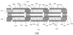
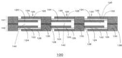
- FIG. 1 is a schematic cross-sectional view of a fuel cell module according to Example 1.
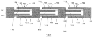
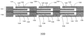
- FIG. 6 is a schematic cross-sectional view of a fuel cell module according to Example 2.
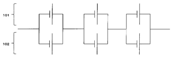
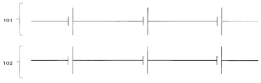
- FIG. It is the schematic which shows the electric circuit at the time of taking the structure of Example 1 and Example 2.
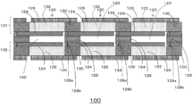
- FIG. 6 is a schematic cross-sectional view of a fuel cell module according to Example 3.
- FIG. 6 is a schematic cross-sectional view of a fuel cell module according to Example 4.
- the fixing member 128 is a schematic cross-sectional view showing an insulating sheet shape over the entire surface. It is the schematic which shows the electric circuit at the time of taking the structure of Example 3 and Example 4.
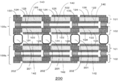
- FIG. 6 is a schematic cross-sectional view of a fuel cell stack according to Example 5.
- FIG. 6 is a schematic cross-sectional view of a fuel cell stack according to Example 6.
- FIG. It is a disassembled perspective view which shows the structure of the fuel cell stack containing the fuel cell module which concerns on this embodiment.
- FIG. 1 is a schematic cross-sectional view illustrating the configuration of the fuel cell module according to the first embodiment.
- the fuel cell module 100 includes a first fuel cell layer 101, a second fuel cell layer 102, and a fixing member 128.
- the first fuel cell layer 101 and the second fuel cell layer 102 are arranged via a fixing member 128 so that the anode catalyst layers 124 face each other. By arranging in this way, a fuel gas space 140 through which hydrogen gas flows is formed, and conventionally used separators can be reduced.
- the first fuel cell layer 101 and the second fuel cell layer 102 include a plurality of membrane electrode assemblies 120 and an interconnector 130 arranged in a plane.
- Each membrane electrode assembly 120 is at least partially opposed to the electrolyte membrane 122, the anode catalyst layer 124 provided on one surface of the electrolyte membrane 122, and the other surface of the electrolyte membrane 122.
- a cathode catalyst layer 126 provided as described above.
- the anode catalyst layer 124 of each membrane electrode assembly 120 is provided on one surface of the electrolyte membrane 122 so as to be spaced from each other. Further, the cathode catalyst layer 126 of each membrane electrode assembly 120 is provided on the other surface of the electrolyte membrane 122 so as to be spaced from each other. An electrolyte membrane 122 is sandwiched between a pair of anode catalyst layer 124 and cathode catalyst layer 126 to constitute a membrane electrode assembly 120 (sometimes referred to as a single cell).
- the anode catalyst layer 124 is supplied with hydrogen as a fuel gas. Air is supplied to the cathode catalyst layer 126 as an oxidant. Each membrane electrode assembly 120 generates power by an electrochemical reaction between hydrogen and oxygen in the air.
- the anode catalyst layer 124 and the cathode catalyst layer 126 have ion exchangers and catalyst particles, and in some cases, carbon particles supporting the catalyst particles.
- the ion exchangers included in the anode catalyst layer 124 and the cathode catalyst layer 126 are used for improving the adhesion between the catalyst particles and the electrolyte membrane 122.
- catalyst metals include Sc, Y, Ti, Zr, V, Nb, Fe, Co, Ni, Ru, Rh, Pd, Pt, Os, Ir, alloys selected from lanthanoid series elements and actinoid series elements, A simple substance is mentioned. When the catalyst is supported, furnace black, acetylene black, ketjen black, carbon nanotubes or the like may be used as the carbon particles.
- the thicknesses of the anode catalyst layer 124 and the cathode catalyst layer 126 are each about 10 to 40 ⁇ m, for example.
- the electrolyte membrane 122 preferably exhibits good ion conductivity in a wet state, and functions as an ion exchange membrane that moves protons between the anode catalyst layer 124 and the cathode catalyst layer 126.
- the electrolyte membrane 122 is formed of a solid polymer material such as a fluorine-containing polymer or a non-fluorine polymer, and for example, a sulfonic acid type perfluorocarbon polymer, a polysulfone resin, a perfluorocarbon polymer having a phosphonic acid group or a carboxylic acid group. Etc. can be used.
- sulfonic acid type perfluorocarbon polymer examples include Nafion (registered trademark) membrane (manufactured by DuPont).
- non-fluorine polymers examples include sulfonated aromatic polyetheretherketone and polysulfone.
- the thickness of the electrolyte membrane 122 is, for example, about 10 to 200 ⁇ m.
- the interconnector 130 forms an electrical path from one anode catalyst layer 124 of the adjacent membrane electrode assembly 120 to the other cathode catalyst layer 126 of the adjacent membrane electrode assembly 120 to electrically connect the adjacent single cells. It is a member for connecting to.
- the fixing member 128 includes an anode catalyst layer 124 formed on the interconnector 130 of the first fuel cell layer 101 and an anode catalyst layer 124 formed on the interconnector 130 of the second fuel cell layer 102. Can be placed between.
- the first fuel cell layer 101 and the second fuel cell layer 102 are arranged via the fixing member 128 so that the anode catalyst layers 124 face each other. By arranging in this way, a common fuel gas space 140 through which hydrogen gas flows is formed, and it is possible to reduce the number of separators conventionally used for flowing hydrogen gas.
- the fixing member 128 is preferably arranged for each interconnector 130. By arranging in this way, the expansion of the fuel gas space 140 due to the pressure of the hydrogen gas can be suppressed, and damage to the first fuel cell layer 101 or the second fuel cell layer 102 can be prevented. it can.
- the fixing member 128 may include a conductive material such as carbon, nickel, copper, or iron.
- FIG. 2 is a schematic cross-sectional view illustrating the configuration of the fuel cell module 100 according to the second embodiment.
- the main difference from the first embodiment is that the interconnector 130 protrudes from the anode catalyst layer 124. Thereby, the interconnector 130 can also serve as the fixing member 128 in the first embodiment.
- the interconnector 130 and the cathode catalyst layer 126 are substantially on the same plane, and the anode catalyst layer 124 and the adjacent cathode catalyst layer 126 are electrically connected via the side surface of the interconnector 130. Are connected in series.
- the interconnector 130 since the interconnector 130 also serves as the fixing member 128 in the first embodiment, it is not necessary to prepare the fixing member 128 separately, and thus further downsizing is possible. Become.
- FIG. 3 is a schematic diagram showing an electric circuit in the first embodiment and the second embodiment. Since the fixing member 128 includes a conductive material as in the first embodiment, or the interconnector 130 also serves as the fixing member as in the second embodiment, the interconnector 130 of the first fuel cell layer 101 and the Since the interconnector 130 of the second fuel cell layer 101 can be electrically connected, the opposing single cells are connected in parallel as shown in FIG. 3, and the output can be stabilized even if the single cells vary. it can.
- FIG. 4 is a schematic cross-sectional view illustrating the configuration of the fuel cell module 100 according to the third embodiment.
- the fixing member 128 is made of an insulating material.
- the convex portions 128 a and 128 b of the fixing member 128 can be arranged at intervals provided between the anode catalyst layers 124 of the membrane electrode assemblies 120.
- FIG. 5 is a schematic cross-sectional view illustrating the configuration of the fuel cell module 100 according to the fourth embodiment. As shown in FIG. 5, in this example, an insulating fixing member 128 is interposed between the interconnector 130 of the first fuel cell layer 101 and the interconnector 130 of the second fuel cell layer 102. The configuration is substantially the same as in the second embodiment.
- the fixing member 128 is made of an insulating material as in the third embodiment and the fourth embodiment, when the first fuel cell layer 101 and the second fuel cell layer 102 are arranged to face each other, a little Even if misalignment occurs, it is possible to prevent occurrence of a short circuit due to contact between the anode catalyst layer 124 of the first fuel cell layer 101 and the anode catalyst layer 124 of the adjacent second fuel cell layer 102. .
- the interconnector 130 may be more convex than the surface of the cathode catalyst layer 126.
- the fixing member 128 may be an insulating sheet covering the entire surface. In this case, it is preferable that the insulating sheet is permeable to gas such as hydrogen gas.
- FIG. 7 is a schematic diagram showing an electric circuit in the third and fourth embodiments. Since the fixing member 128 is an insulating material or the insulating fixing member 128 is interposed between each interconnector 130, the single cells are not connected in parallel as shown in FIG.
- first fuel cell layer 101 and the second fuel cell layer 102 are electrically connected at the end, and the first fuel cell layer 101 and the second fuel cell layer 102 are connected to each other. It may be a parallel connection.
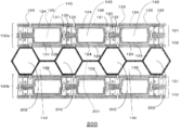
- FIG. 8 is a schematic cross-sectional view of the fuel cell stack 200 according to the fifth embodiment.
- the fuel cell stack 200 includes a first fuel cell module 100a and a second fuel cell module 100b, and is stacked via a cooling unit 201 for cooling the fuel cell module.
- the first fuel cell module 100a and the second fuel cell module 100b each include a first fuel cell layer 101 and a second fuel cell layer 102.
- the cathode catalyst layer 126 of the second fuel cell layer 102 that is a component of the first fuel cell module 100a and the cathode catalyst layer 126 of the first fuel cell layer 101 that is a component of the second fuel cell module 100b are included. It arrange
- the cooling section 201 may be provided with a refrigerant flow path 202.
- the cooling unit 201 including the refrigerant flow path 202 on the cathode side.
- the refrigerant water, alcohol, oil, or the like can be used.
- the oxidant gas space 142 containing oxygen gas can be formed, so that a separator for circulating the oxidant gas is not required, and the fuel cell can be made compact.
- the cathode side is likely to be hotter than the anode side, it is particularly preferable to install the cooling unit 201 on the cathode side.
- the cooling unit 201 is disposed between the cathode catalyst layer 126 of the first fuel cell layer 101 or the cathode catalyst layer 126 of the second fuel cell layer 102.
- the first fuel cell layer 101 or the second fuel cell layer 102 may be installed on the interconnector 130. Since the cooling unit 201 is on the interconnector 130, the diffusion of the oxidant gas to the cathode is not hindered.
- the cooling unit 201 is made of an insulating material.
- insulating materials such as lighter resin and anodized aluminum, can be used, and also a fuel cell can be reduced in weight.
- a heat radiating fin may be provided as the cooling unit 201.
- a heat radiating fin By installing the radiating fins, it is possible to cool with an oxidant gas to be supplied to the cathode, and a refrigerant such as water, alcohol, oil or the like becomes unnecessary.
- FIG. 9 is a schematic cross-sectional view of the fuel cell stack 200 according to the sixth embodiment.
- the fuel cell stack 200 includes a first fuel cell module 100a and a second fuel cell module 100b, and is stacked via a cooling unit 201.
- the first fuel cell module 100 a includes a first fuel cell layer 101 and a second fuel cell layer 102, and an anode catalyst layer 124 of the first fuel cell layer 101 and an anode of the second fuel cell layer 102.
- the catalyst layers 124 are arranged so as to face each other. By disposing in this way, a fuel gas space 140 through which hydrogen gas flows is formed, and it is possible to reduce the number of separators conventionally used for flowing hydrogen gas.
- the first insulating layer 131 and the second insulating layer 132 are provided at both ends of the interconnector 130 of the first fuel cell layer 101 or the second fuel cell layer 102.
- the anode catalyst layer 124 existing on the first insulating layer 131 and the cathode catalyst layer existing on the second insulating layer 132 are removed by a laser or the like to form a gap 133. is doing.
- the cooling unit 201 may be integrated. In this case, a hole for allowing gas to pass through may be formed in the cooling unit 201.
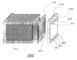
- FIG. 10 is an exploded perspective view showing the configuration of the fuel cell stack including the fuel cell module according to the present embodiment described above. As shown in FIG. 10, a plurality of fuel cell stacks are fixed by the current collector 211, and each of the plurality of fuel cell modules can be electrically connected in series or in parallel.
- the end plate 210 includes a hydrogen gas supply manifold 220, a hydrogen gas discharge manifold 221, an oxidant gas supply manifold 230, an oxidant gas discharge manifold 231, a cooling water supply manifold 240, A cooling water discharge manifold 241 may be provided.
- an insulating material is particularly suitable. By doing in this way, insulating materials, such as lighter resin and anodized aluminum, can be used, and also a fuel cell can be reduced in weight.
- the anode catalyst layer 124 of the membrane electrode assembly 120 of the first fuel cell layer 101 and the anode catalyst layer 124 of the membrane electrode assembly 120 of the second fuel cell layer 102 are opposed to each other.
- the cathode catalyst layer 126 of the membrane electrode assembly 120 of the first fuel cell layer 101 and the second fuel are shown. You may arrange
- the present invention can be used for fuel cells.
- Fuel cell module 101 first fuel cell layer 102 second fuel cell layer 120 membrane electrode assembly 122 electrolyte membrane 124 anode catalyst layer 126 cathode catalyst layer 128 fixing member 130 interconnector 131 first insulating layer 132 second insulating layer 140 Fuel gas space 142 Oxidant gas space 200 Fuel cell stack 201 Cooling unit 202 Refrigerant flow path 210 End plate 220 Hydrogen gas supply manifold 221 Hydrogen gas discharge manifold 230 Oxidant gas supply manifold 231 Oxidant gas discharge manifold 240 Cooling water supply manifold 241 Cooling water discharge manifold
Landscapes
- Chemical & Material Sciences (AREA)
- Chemical Kinetics & Catalysis (AREA)
- Electrochemistry (AREA)
- General Chemical & Material Sciences (AREA)
- Life Sciences & Earth Sciences (AREA)
- Engineering & Computer Science (AREA)
- Manufacturing & Machinery (AREA)
- Sustainable Development (AREA)
- Sustainable Energy (AREA)
- Fuel Cell (AREA)
Abstract
Description
アノード:H2 → 2H+ + 2e- ・・・(1)
カソード:1/2O2+2H++2e- → H2O ・・・(2)
アノードにおいては、供給された水素が上記式(1)に示されるように水素イオンと電子に分解される。このうち水素イオンは固体高分子電解質膜の内部をカソードに向かって移動し、電子は外部回路を通ってアノードに移動する。一方、カソードにおいては、カソードに供給された酸化剤ガスに含まれる酸素がアノードから移動してきた水素イオンおよび電子と反応し、上記(2)に示されるように水が生成する。このように、外部回路では、アノードからカソードに向かって電子が移動するため、電力が取り出される。
図1は、実施例1に係る燃料電池モジュールの構成を示す模式的断面図である。図1に示すように、燃料電池モジュール100は、第1の燃料電池レイヤー101と第2の燃料電池レイヤー102と固定部材128とを備える。
図2は、実施例2に係る燃料電池モジュール100の構成を示す模式的断面図である。図2に示すように、前記実施例1との主たる相違点は、インターコネクタ130がアノード触媒層124よりも突出しているところである。これにより、インターコネクタ130が前記実施例1における固定部材128を兼ねることができる。また、その他の相違点として、インターコネクタ130とカソード触媒層126とが略同一平面上にあると共に、アノード触媒層124と隣接するカソード触媒層126とが、インターコネクタ130の側面を介して電気的に直列接続されている。
図4は、実施例3に係る燃料電池モジュール100の構成を示す模式的断面図である。図4に示すように、前記実施例1との主たる相違点は、固定部材128が絶縁材料である点である。また、固定部材128の固定する力を高めるために、各膜電極接合体120の各アノード触媒層124間に設けられた間隔に固定部材128の凸部128a及び128bを配置することができる。
図5は、実施例4に係る燃料電池モジュール100の構成を示す模式的断面図である。図5に示すように、本例では、第1の燃料電池レイヤー101のインターコネクタ130と第2の燃料電池レイヤー102のインターコネクタ130との間に絶縁性の固定部材128を介した以外は、前記実施例2と略同等の構成となっている。
図8は、実施例5に係る燃料電池スタック200の模式的断面図である。燃料電池スタック200は、第1の燃料電池モジュール100aと第2の燃料電池モジュール100bとからなり、燃料電池モジュールを冷却するための冷却部201を介して積層している。
図9は、実施例6に係る燃料電池スタック200の模式的断面図である。燃料電池スタック200は、第1の燃料電池モジュール100aと第2の燃料電池モジュール100bとからなり、冷却部201を介して積層されている。
101 第1の燃料電池レイヤー
102 第2の燃料電池レイヤー
120 膜電極接合体
122 電解質膜
124 アノード触媒層
126 カソード触媒層
128 固定部材
130 インターコネクタ
131 第1絶縁層
132 第2絶縁層
140 燃料ガス空間
142 酸化剤ガス空間
200 燃料電池スタック
201 冷却部
202 冷媒流路
210 エンドプレート
220 水素ガス供給用マニホールド
221 水素ガス排出用マニホールド
230 酸化剤ガス供給用マニホールド
231 酸化剤ガス排出用マニホールド
240 冷却水供給用マニホールド
241 冷却水排出用マニホールド
Claims (7)
- 電解質膜と、前記電解質膜の一方の面に設けられたアノードと、前記電解質膜の他方の面に設けられたカソードとを有し、平面状に配列された複数の膜電極接合体と、隣接する前記膜電極接合体の一方のアノードと他方のカソードとを電気的に接続するためのインターコネクタと、を備えた第1の燃料電池レイヤー及び第2の燃料電池レイヤーからなり、前記第1の燃料電池レイヤーの膜電極接合体と前記第2の燃料電池レイヤーの膜電極接合体の同極が対向するように、前記第1の燃料電池レイヤーと前記第2の燃料電池レイヤーが配置されたことを特徴とする燃料電池モジュール。
- 前記第1の燃料電池レイヤーのインターコネクタと前記第2の燃料電池レイヤーのインターコネクタとの間に固定部材を有することを特徴とする請求項1に記載の燃料電池モジュール。
- 前記固定部材が、前記第1の燃料電池レイヤーのインターコネクタと前記第2の燃料電池レイヤーのインターコネクタとを電気的に接続する導電材料を含むことを特徴とする請求項2に記載の燃料電池モジュール。
- 前記固定部材が、絶縁材料であることを特徴とする請求項2に記載の燃料電池モジュール。
- 前記同極はアノードである請求項1~4のいずれか1項に記載の燃料電池モジュール。
- 請求項1~5のいずれかに記載の燃料電池モジュールの前記第1の燃料電池レイヤーまたは前記第2の燃料電池レイヤーのインターコネクタ上に冷却部を設け、前記冷却部を介して燃料電池モジュールが積層された燃料電池スタック。
- 前記冷却部が絶縁材料から成ることを特徴とする請求項6に記載の燃料電池スタック。
Priority Applications (2)
| Application Number | Priority Date | Filing Date | Title |
|---|---|---|---|
| JP2016505044A JP6477681B2 (ja) | 2014-02-27 | 2015-02-18 | 燃料電池モジュールおよび燃料電池スタック |
| US15/038,905 US9935323B2 (en) | 2014-02-27 | 2015-02-18 | Fuel cell module and fuel cell stack |
Applications Claiming Priority (2)
| Application Number | Priority Date | Filing Date | Title |
|---|---|---|---|
| JP2014-036329 | 2014-02-27 | ||
| JP2014036329 | 2014-02-27 |
Publications (1)
| Publication Number | Publication Date |
|---|---|
| WO2015129206A1 true WO2015129206A1 (ja) | 2015-09-03 |
Family
ID=54008543
Family Applications (1)
| Application Number | Title | Priority Date | Filing Date |
|---|---|---|---|
| PCT/JP2015/000749 Ceased WO2015129206A1 (ja) | 2014-02-27 | 2015-02-18 | 燃料電池モジュールおよび燃料電池スタック |
Country Status (3)
| Country | Link |
|---|---|
| US (1) | US9935323B2 (ja) |
| JP (1) | JP6477681B2 (ja) |
| WO (1) | WO2015129206A1 (ja) |
Cited By (5)
| Publication number | Priority date | Publication date | Assignee | Title |
|---|---|---|---|---|
| KR20180019942A (ko) * | 2016-08-17 | 2018-02-27 | 류보현 | 가압이 가능한 고온형 연료전지 단위셀 조립체 |
| KR20180019943A (ko) * | 2016-08-17 | 2018-02-27 | 류보현 | 가압 가능한 고온형 연료전지 단위셀이 적층된 스택 조립체 |
| WO2019189062A1 (ja) * | 2018-03-30 | 2019-10-03 | 本田技研工業株式会社 | 燃料電池 |
| WO2019189058A1 (ja) * | 2018-03-30 | 2019-10-03 | 本田技研工業株式会社 | 燃料電池 |
| WO2019189060A1 (ja) * | 2018-03-30 | 2019-10-03 | 本田技研工業株式会社 | 燃料電池 |
Citations (7)
| Publication number | Priority date | Publication date | Assignee | Title |
|---|---|---|---|---|
| JP2006134588A (ja) * | 2004-11-02 | 2006-05-25 | Nec Corp | 燃料電池および燃料電池の制御方法 |
| JP2008108677A (ja) * | 2006-10-27 | 2008-05-08 | Sony Corp | 電気化学デバイス |
| JP2008210714A (ja) * | 2007-02-27 | 2008-09-11 | Sanyo Electric Co Ltd | 燃料電池および燃料電池用集電体の接続方法 |
| JP2009231111A (ja) * | 2008-03-24 | 2009-10-08 | Sony Corp | 燃料電池ユニット、燃料電池スタックおよび電子機器 |
| JP2010086808A (ja) * | 2008-09-30 | 2010-04-15 | Dainippon Printing Co Ltd | 単室型固体酸化物形燃料電池及びそのスタック構造 |
| JP2010231892A (ja) * | 2009-03-25 | 2010-10-14 | Sanyo Electric Co Ltd | 燃料電池 |
| JP2010244721A (ja) * | 2009-04-01 | 2010-10-28 | Sharp Corp | 燃料電池スタック |
Family Cites Families (5)
| Publication number | Priority date | Publication date | Assignee | Title |
|---|---|---|---|---|
| US7981561B2 (en) * | 2005-06-15 | 2011-07-19 | Ati Properties, Inc. | Interconnects for solid oxide fuel cells and ferritic stainless steels adapted for use with solid oxide fuel cells |
| US7638219B2 (en) | 2003-03-07 | 2009-12-29 | Honda Motor Co., Ltd. | Fuel cell without Z-like connection plates and the method producing the same |
| JP2004273264A (ja) | 2003-03-07 | 2004-09-30 | Honda Motor Co Ltd | 燃料電池スタック |
| US20080199751A1 (en) * | 2007-02-20 | 2008-08-21 | Commonwealth Scientific And Industrial Research Organisation | Bipolar plate for an air breathing fuel cell stack |
| US20140242476A1 (en) * | 2013-02-28 | 2014-08-28 | Michael Kühne | Operating battery stack system performance by alternating the flow of heat carrying fluid used therein |
-
2015
- 2015-02-18 JP JP2016505044A patent/JP6477681B2/ja not_active Expired - Fee Related
- 2015-02-18 US US15/038,905 patent/US9935323B2/en not_active Expired - Fee Related
- 2015-02-18 WO PCT/JP2015/000749 patent/WO2015129206A1/ja not_active Ceased
Patent Citations (7)
| Publication number | Priority date | Publication date | Assignee | Title |
|---|---|---|---|---|
| JP2006134588A (ja) * | 2004-11-02 | 2006-05-25 | Nec Corp | 燃料電池および燃料電池の制御方法 |
| JP2008108677A (ja) * | 2006-10-27 | 2008-05-08 | Sony Corp | 電気化学デバイス |
| JP2008210714A (ja) * | 2007-02-27 | 2008-09-11 | Sanyo Electric Co Ltd | 燃料電池および燃料電池用集電体の接続方法 |
| JP2009231111A (ja) * | 2008-03-24 | 2009-10-08 | Sony Corp | 燃料電池ユニット、燃料電池スタックおよび電子機器 |
| JP2010086808A (ja) * | 2008-09-30 | 2010-04-15 | Dainippon Printing Co Ltd | 単室型固体酸化物形燃料電池及びそのスタック構造 |
| JP2010231892A (ja) * | 2009-03-25 | 2010-10-14 | Sanyo Electric Co Ltd | 燃料電池 |
| JP2010244721A (ja) * | 2009-04-01 | 2010-10-28 | Sharp Corp | 燃料電池スタック |
Cited By (13)
| Publication number | Priority date | Publication date | Assignee | Title |
|---|---|---|---|---|
| KR20180019942A (ko) * | 2016-08-17 | 2018-02-27 | 류보현 | 가압이 가능한 고온형 연료전지 단위셀 조립체 |
| KR20180019943A (ko) * | 2016-08-17 | 2018-02-27 | 류보현 | 가압 가능한 고온형 연료전지 단위셀이 적층된 스택 조립체 |
| KR101951078B1 (ko) | 2016-08-17 | 2019-02-21 | 류보현 | 가압이 가능한 고온형 연료전지 단위셀 조립체 |
| KR101962267B1 (ko) | 2016-08-17 | 2019-03-26 | 류보현 | 가압 가능한 고온형 연료전지 단위셀이 적층된 스택 조립체 |
| WO2019189062A1 (ja) * | 2018-03-30 | 2019-10-03 | 本田技研工業株式会社 | 燃料電池 |
| WO2019189058A1 (ja) * | 2018-03-30 | 2019-10-03 | 本田技研工業株式会社 | 燃料電池 |
| WO2019189060A1 (ja) * | 2018-03-30 | 2019-10-03 | 本田技研工業株式会社 | 燃料電池 |
| CN111989810A (zh) * | 2018-03-30 | 2020-11-24 | 本田技研工业株式会社 | 燃料电池 |
| JPWO2019189058A1 (ja) * | 2018-03-30 | 2021-01-07 | 本田技研工業株式会社 | 燃料電池 |
| JPWO2019189062A1 (ja) * | 2018-03-30 | 2021-01-07 | 本田技研工業株式会社 | 燃料電池 |
| JPWO2019189060A1 (ja) * | 2018-03-30 | 2021-01-14 | 本田技研工業株式会社 | 燃料電池 |
| US11271223B2 (en) | 2018-03-30 | 2022-03-08 | Honda Motor Co., Ltd. | Fuel cell |
| CN111989810B (zh) * | 2018-03-30 | 2023-10-27 | 本田技研工业株式会社 | 燃料电池 |
Also Published As
| Publication number | Publication date |
|---|---|
| JPWO2015129206A1 (ja) | 2017-03-30 |
| JP6477681B2 (ja) | 2019-03-06 |
| US20170162883A1 (en) | 2017-06-08 |
| US9935323B2 (en) | 2018-04-03 |
Similar Documents
| Publication | Publication Date | Title |
|---|---|---|
| JP5180484B2 (ja) | 燃料電池スタック | |
| US7875405B2 (en) | Side-by-side fuel cells | |
| JP2012212678A (ja) | 燃料電池 | |
| JP6477681B2 (ja) | 燃料電池モジュールおよび燃料電池スタック | |
| CA2700901C (en) | Fuel cell stack with thermally insulating non-power-generating cells | |
| JP2008210714A (ja) | 燃料電池および燃料電池用集電体の接続方法 | |
| US20100062302A1 (en) | Metal support and solid oxide fuel cell including the same | |
| US20110294031A1 (en) | Composite membrane and fuel cell | |
| JP5362406B2 (ja) | 燃料電池 | |
| JP2009070622A (ja) | 燃料電池およびその製造方法 | |
| JP4828841B2 (ja) | 燃料電池 | |
| CN101116216B (zh) | 燃料电池模块和设有燃料电池模块的燃料电池 | |
| JP2010061986A (ja) | 燃料電池スタック | |
| JP2009123446A (ja) | 固体高分子型燃料電池 | |
| KR101542970B1 (ko) | 연료 전지 스택 | |
| JP2004185904A (ja) | 燃料電池 | |
| JP2017126472A (ja) | 燃料電池 | |
| JP4100096B2 (ja) | 固体高分子型燃料電池 | |
| US9385389B2 (en) | Fuel cell | |
| JP2021044167A (ja) | 燃料電池スタック | |
| JP2009199755A (ja) | 燃料電池 | |
| JPWO2012124326A1 (ja) | 燃料電池および燃料電池の製造方法 | |
| CN110061276A (zh) | 燃料电池组的制造方法 | |
| JP2014049345A (ja) | 燃料電池システム | |
| JP6606357B2 (ja) | 燃料電池スタック及びその放熱調整方法 |
Legal Events
| Date | Code | Title | Description |
|---|---|---|---|
| 121 | Ep: the epo has been informed by wipo that ep was designated in this application |
Ref document number: 15754517 Country of ref document: EP Kind code of ref document: A1 |
|
| WWE | Wipo information: entry into national phase |
Ref document number: 15038905 Country of ref document: US |
|
| ENP | Entry into the national phase |
Ref document number: 2016505044 Country of ref document: JP Kind code of ref document: A |
|
| NENP | Non-entry into the national phase |
Ref country code: DE |
|
| 122 | Ep: pct application non-entry in european phase |
Ref document number: 15754517 Country of ref document: EP Kind code of ref document: A1 |