WO2015128928A1 - オイルセパレータ - Google Patents
オイルセパレータ Download PDFInfo
- Publication number
- WO2015128928A1 WO2015128928A1 PCT/JP2014/054439 JP2014054439W WO2015128928A1 WO 2015128928 A1 WO2015128928 A1 WO 2015128928A1 JP 2014054439 W JP2014054439 W JP 2014054439W WO 2015128928 A1 WO2015128928 A1 WO 2015128928A1
- Authority
- WO
- WIPO (PCT)
- Prior art keywords
- oil
- spindle
- oil separator
- gas
- rotor
- Prior art date
Links
Images


Classifications
-
- B—PERFORMING OPERATIONS; TRANSPORTING
- B01—PHYSICAL OR CHEMICAL PROCESSES OR APPARATUS IN GENERAL
- B01D—SEPARATION
- B01D45/00—Separating dispersed particles from gases or vapours by gravity, inertia, or centrifugal forces
- B01D45/12—Separating dispersed particles from gases or vapours by gravity, inertia, or centrifugal forces by centrifugal forces
- B01D45/14—Separating dispersed particles from gases or vapours by gravity, inertia, or centrifugal forces by centrifugal forces generated by rotating vanes, discs, drums or brushes
-
- B—PERFORMING OPERATIONS; TRANSPORTING
- B01—PHYSICAL OR CHEMICAL PROCESSES OR APPARATUS IN GENERAL
- B01D—SEPARATION
- B01D45/00—Separating dispersed particles from gases or vapours by gravity, inertia, or centrifugal forces
- B01D45/12—Separating dispersed particles from gases or vapours by gravity, inertia, or centrifugal forces by centrifugal forces
-
- B—PERFORMING OPERATIONS; TRANSPORTING
- B04—CENTRIFUGAL APPARATUS OR MACHINES FOR CARRYING-OUT PHYSICAL OR CHEMICAL PROCESSES
- B04B—CENTRIFUGES
- B04B5/00—Other centrifuges
- B04B5/005—Centrifugal separators or filters for fluid circulation systems, e.g. for lubricant oil circulation systems
-
- B—PERFORMING OPERATIONS; TRANSPORTING
- B04—CENTRIFUGAL APPARATUS OR MACHINES FOR CARRYING-OUT PHYSICAL OR CHEMICAL PROCESSES
- B04B—CENTRIFUGES
- B04B5/00—Other centrifuges
- B04B5/12—Centrifuges in which rotors other than bowls generate centrifugal effects in stationary containers
-
- B—PERFORMING OPERATIONS; TRANSPORTING
- B04—CENTRIFUGAL APPARATUS OR MACHINES FOR CARRYING-OUT PHYSICAL OR CHEMICAL PROCESSES
- B04B—CENTRIFUGES
- B04B7/00—Elements of centrifuges
- B04B7/02—Casings; Lids
-
- F—MECHANICAL ENGINEERING; LIGHTING; HEATING; WEAPONS; BLASTING
- F01—MACHINES OR ENGINES IN GENERAL; ENGINE PLANTS IN GENERAL; STEAM ENGINES
- F01M—LUBRICATING OF MACHINES OR ENGINES IN GENERAL; LUBRICATING INTERNAL COMBUSTION ENGINES; CRANKCASE VENTILATING
- F01M13/00—Crankcase ventilating or breathing
- F01M13/04—Crankcase ventilating or breathing having means for purifying air before leaving crankcase, e.g. removing oil
-
- B—PERFORMING OPERATIONS; TRANSPORTING
- B04—CENTRIFUGAL APPARATUS OR MACHINES FOR CARRYING-OUT PHYSICAL OR CHEMICAL PROCESSES
- B04B—CENTRIFUGES
- B04B5/00—Other centrifuges
- B04B5/12—Centrifuges in which rotors other than bowls generate centrifugal effects in stationary containers
- B04B2005/125—Centrifuges in which rotors other than bowls generate centrifugal effects in stationary containers the rotors comprising separating walls
-
- F—MECHANICAL ENGINEERING; LIGHTING; HEATING; WEAPONS; BLASTING
- F01—MACHINES OR ENGINES IN GENERAL; ENGINE PLANTS IN GENERAL; STEAM ENGINES
- F01M—LUBRICATING OF MACHINES OR ENGINES IN GENERAL; LUBRICATING INTERNAL COMBUSTION ENGINES; CRANKCASE VENTILATING
- F01M13/00—Crankcase ventilating or breathing
- F01M13/04—Crankcase ventilating or breathing having means for purifying air before leaving crankcase, e.g. removing oil
- F01M2013/0422—Separating oil and gas with a centrifuge device
Definitions
- the present invention relates to an oil separator that separates mist oil contained in a gas to be treated from gas.
- an oil separator that separates mist oil contained in a gas to be treated from gas.
- an oil separator disclosed in Patent Document 1 includes a cylindrical fixed housing and a cylindrical fixed casing having a ceiling portion, and a truncated cone-shaped partition having an opening on the upper surface, and a lower chamber (lower storage chamber).
- the upper chamber (upper accommodation chamber) is partitioned.
- a centrifugal rotor for purifying oil is disposed in the lower chamber, and a gas purifying device for purifying gas is disposed in the upper chamber.
- the lower end of the fixed housing is joined to the base, and the lower chamber communicates with the internal space of the cylindrical base. This cylindrical base is communicated with the combustion engine, and the purified oil is returned and gas from the crankcase is introduced.
- the centrifugal rotor and the gas purification device are connected by a tubular support member, and are configured to be rotatable around a fixed shaft inserted through the support member.
- a separation chamber is provided inside the centrifugal rotor. Oil is supplied to the separation chamber through a gap between the support member and the fixed shaft and a hole opened in the support member. The supplied oil is purified in the separation chamber and then discharged to the side through a discharge port provided on the bottom surface of the centrifugal rotor. The oil discharge generates a driving force for rotating the centrifugal rotor and the gas purification device.
- the gas purification device is rotated at a high speed in order to separate the mist oil contained in the gas to be treated from the gas.
- a swirling flow of air is generated in the internal space.
- the separated oil travels on the inner surface of the upper chamber on this swirling flow.
- the present invention has been made in view of such circumstances, and an object thereof is to increase the removal efficiency of oil contained in the gas to be treated.
- the present invention provides an oil separator for separating mist-like oil contained in a gas to be processed, which is provided so as to be rotatable together with a spindle, and is stacked in the axial direction of the spindle.
- the oil that moves along the inner surface of the side wall portion of the upper case is captured and aggregated by the vertical ribs. Since the self-weight increases due to the aggregation, the oil after the aggregation flows down along the vertical ribs against the swirling flow. As a result, the amount of oil that rises on the swirling flow and is discharged together with the gas to be processed can be reduced, and the oil removal efficiency can be increased.
- a cylindrical guide rib is provided at a position above the separation disk in the housing to guide fluid flowing downward toward the center side in plan view along the inner surface of the upper case.
- the oil after separation that has not been captured by the vertical ribs can be captured by the guide ribs, so that the oil removal efficiency can be further increased.
- the oil separator when the guide rib is provided with a guide claw protruding downward from the lower edge of the guide rib, the oil captured by the guide rib can be aggregated and easily dropped. Therefore, the oil removal efficiency can be further increased.
- oil separator when the guide claw is constituted by a plurality of small pieces arranged with a predetermined gap, oil captured by the guide ribs can be caught in the gap between the adjacent small pieces, Oil aggregation can be easily performed.
- the removal efficiency of the oil contained in the gas to be treated can be increased.
- FIG. 1 It is the schematic which shows a closed type crankcase ventilation system. It is the perspective view which looked at the oil separator from the back diagonally upper side. It is a disassembled perspective view of an oil separator. It is sectional drawing of the upper half part in an oil separator. It is sectional drawing of an oil separator. It is sectional drawing explaining the internal structure of an upper case and a lower case. It is an enlarged view explaining the vertical rib provided in the upper case. It is a figure explaining the guide rib and guide claw provided in the upper case. It is a figure explaining the structure of a guidance nail
- FIG. 1 a closed crankcase ventilation system 1 (hereinafter referred to as a ventilation system 1) shown in FIG. 1 will be described as an example.
- the ventilation system 1 has an oil separator 2 and a breather pipe 3.
- the oil separator 2 processes blow-by gas (corresponding to a processing target gas containing mist-like oil) discharged from the engine 4 to separate the mist-like oil.
- the oil separator 2 is attached to the side surface of the engine 4.
- the breather pipe 3 defines a reduction flow path for reducing the processed blow-by gas discharged from the oil separator 2 to the intake side flow path of the engine 4.
- blow-by gas discharged from the engine 4 flows into an oil separator 2 provided on the side of the engine 4. Then, the oil separated by the oil separator 2 is returned to the engine 4.
- the treated blow-by gas is discharged from the upper end of the oil separator 2 and then returned to the intake-side flow path 5 through the breather pipe 3. Specifically, it is reduced to a portion where the air filter 6 and the turbocharger 7 are connected in the intake side flow path 5. The reduced blow-by gas is mixed with fresh air from the air filter 6 and compressed by the turbocharger 7. Thereafter, it is cooled by the charge cooler 8 and supplied to the engine 4.
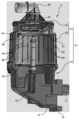
- the oil separator 2 includes a housing 11 having a lower case 12 and an upper case 13. Various parts such as a rotor unit and a PCV valve are accommodated in the internal space (accommodating chamber) of the housing 11 (described later).
- the lower case 12 is a portion that divides the lower portion of the housing 11, and is configured by a box-shaped member having a bottom and an open upper surface.
- the lower case 12 and the communication tube portion are made of a casting, but may be made by molding a resin.
- a circular fitting portion 14 is provided at the upper end portion of the lower case 12 and is fitted to the lower end portion 15 of the upper case 13.
- a communication cylinder portion 16 that communicates with the engine 4 is provided facing rearward.
- a flange 18 coupled to the side surface of the engine 4 is provided at the distal end portion of the communication tube portion 16.
- a cylindrical member 17 for guiding blow-by gas is provided immediately above the communication cylinder portion 16. The rear end of the cylindrical member 17 protrudes rearward from the flange 18.
- a lower end portion of the joint portion 19 protrudes downward from the bottom surface of the lower case 12.
- the joint portion 19 has a cylindrical shape and is connected to one end of the oil supply pipe 9 shown in FIG. As will be described later, a part of the joint portion 19 protrudes upward in the lower case 12.
- the other end of the oil supply pipe 9 is connected to the side surface of the engine 4, and oil is supplied to the oil supply pipe 9 from an oil passage (not shown) provided inside the engine 4. This oil is used as power for rotating the rotor unit 21.
- the upper case 13 is a member that is attached to the lower case 12 from above, and partitions the storage chamber in which the rotor unit 21 and the like are stored together with the lower case 12.
- the upper case 13 has a cylindrical main body cover 22 and a disk-shaped upper surface cover 23.
- a plurality of vertical ribs 24 are formed on the inner surface of the main body cover 22 at equal intervals in the circumferential direction. These vertical ribs 24 are for capturing and agglomerating the separated oil that flows in the circumferential direction along the inner surface of the main body cover 22 to flow downward.
- the vertical rib 24 will be described later.
- the upper surface cover 23 is attached to the upper end portion of the main body cover 22 in an airtight state.
- a cylindrical gas discharge portion 25 is provided at the center of the top cover 23 so as to face upward.
- the gas discharge part 25 is a part for discharging the blow-by gas after processing, and the breather pipe 3 is connected via the outlet pipe 26.
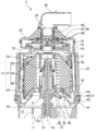
- a rotor unit 21 and a partition member 27 are disposed inside the oil separator 2. Further, as shown in the cross-sectional view of FIG. 4, a PCV valve 28 is attached inside the upper surface cover 23.
- the rotor unit 21 is a mechanism for separating mist-like oil contained in blow-by gas, and has a rotor 31, a spindle 32, and a spindle shaft 33 as shown in FIG.
- the rotor 31 is a part that aggregates mist-like oil by rotation and separates it from blow-by gas, and includes a plurality of separation disks 34, an upper holder 35, and a lower holder 36.
- the separation disk 34 is a ring-shaped plate material that is inclined downward toward the outer peripheral side, in other words, a plate material that is processed into a side surface shape of a truncated cone.
- the separation disk 34 of the present embodiment has a thickness of 1 mm or less and is manufactured by resin molding. These separation disks 34 are stacked in the axial direction of the spindle 32. For convenience of explanation, the separation disks 34 are drawn with an interval between them, but the actual interval is set to be extremely narrow (for example, less than 1 mm).
- the upper holder 35 is a member that holds a plurality of stacked separation disks 34 from above, and the lower holder 36 is also a member that holds the separation disk 34 from below.
- a plurality of connecting arms 36a for connecting to the upper holder 35 are provided on the outer peripheral edge of the lower holder 36 (see FIG. 3). In the present embodiment, four connection arms 36a are provided at intervals of 90 degrees in the circumferential direction.
- the rotor 31 has a cylindrical appearance, and the inner peripheral side is a hollow portion and penetrates in the vertical direction. A spindle 32 is inserted into the hollow portion, and the spindle 32 and the rotor 31 are coupled to each other. For this reason, the rotor 31 rotates around the axis of the spindle 32 together with the spindle 32.
- a nozzle 37 projects from the peripheral surface of the spindle 32 below the rotor 31.
- the nozzle 37 is a portion that injects oil supplied through the spindle shaft 33, and generates a driving force for rotating the spindle 32 and the rotor 31.
- the nozzle 37 of the present embodiment has a cylindrical nozzle body 38 whose base end is joined to the spindle 32 and whose tip is closed, and an injection hole 39 provided at the tip of the nozzle body 38. .
- the nozzle body 38 is attached at an angle of 45 degrees obliquely downward with respect to the axial direction of the spindle 32 indicated by reference numeral AL.
- Three nozzle bodies 38 are provided at intervals of 120 degrees in the circumferential direction.
- the injection hole 39 is provided on the side surface of the tip portion of the nozzle body 38. Specifically, the injection hole 39 is provided in a direction orthogonal to the axial direction of the nozzle main body 38 indicated by reference numeral NL and in a direction in which oil is injected in the horizontal direction.
- the spindle shaft 33 is a cylindrical member serving as a bearing for the spindle 32, and supports the spindle 32 in a rotatable state.
- an oil supply path 33 a for supplying oil is formed inside the spindle shaft 33.
- the lower end portion of the spindle shaft 33 is joined to the upper end portion of the joint portion 19 provided in the lower case 12.
- the oil supply pipe 9 is connected to the joint portion 19. For this reason, the oil supplied through the oil supply pipe 9 flows into the spindle shaft 33 after passing through the joint portion 19. Further, after flowing into the nozzle main body 38, it is injected from the injection hole 39.
- the injection hole 39 is provided at the tip of the nozzle body 38 in a direction in which oil is injected in the horizontal direction. And in the three nozzles 37 provided at intervals of 120 degrees, the formation positions of the injection holes 39 are aligned. For this reason, when oil is injected from each injection hole 39, the rotor 31 and the spindle 32 rotate around the spindle shaft 33.
- the partition member 27 partitions the internal space (storage chamber) of the housing 11 into a lower storage chamber 41 (primary separation chamber) and an upper storage chamber 42 (secondary separation chamber). It is a member that forms a communication port 43 that guides the blow-by gas in the side storage chamber 41 to the upper storage chamber 42.
- the partition member 27 has an outer peripheral portion 44 and a tapered portion 45.
- the outer peripheral portion 44 is a portion having a short cylindrical shape, and a flange portion 46 projects laterally in the middle of the height direction.
- the tapered portion 45 is provided on the inner peripheral side with respect to the outer peripheral portion 44, and has a tapered shape that is gradually reduced in diameter from the lower end of the outer peripheral portion 44 upward.
- the tapered portion 45 of the present embodiment has an inclined surface 45 a that is inclined at an angle of about 45 degrees with respect to the axis of the spindle 32.
- the upper end opening of the tapered portion 45 forms a communication port 43.
- the partition member 27 is fitted into the fitting portion 14 of the lower case 12 from the inner peripheral side. Then, the flange portion 46 is positioned in contact with the upper end of the fitting portion 14 from above. As a result, the tapered portion 45 is disposed immediately below the lower holder 36 included in the rotor 31. Then, with the partition member 27 as a boundary, the storage chamber is partitioned into a lower storage chamber 41 and an upper storage chamber 42, and the lower storage chamber 41 and the upper storage chamber 42 communicate with each other through the communication port 43. That is, the partition member 27 forms a communication port 43 for guiding the blow-by gas in the lower storage chamber 41 to the upper storage chamber 42 around the spindle 32 at a height between the nozzle 37 and the separation disk 34.
- the lower storage chamber 41 functions as a primary separation chamber for mist oil.
- the PCV valve 28 includes a diaphragm 47, an upper spring 48, and a lower spring 49.
- the diaphragm 47 is a valve body, which is manufactured by molding rubber and resin, and is configured by a disk-shaped member that is slightly inclined downward from the central portion toward the peripheral portion.
- the upper spring 48 and the lower spring 49 are members for supporting the diaphragm 47 in a state in which the diaphragm 47 can move in the vertical direction. That is, the upper spring 48 is disposed at the center of the diaphragm 47 from above, and the lower spring 49 is disposed at the center of the diaphragm 47 from below.
- the diaphragm 47 is sandwiched between the upper spring 48 and the lower spring 49 so as to be supported so as to be movable in the vertical direction.
- the PCV valve 28 is disposed on the upper case 13. Specifically, it is arranged at a position directly below the upper surface cover 23 in a state of being placed on the pedestal 51.
- the pedestal 51 is airtightly covered with a diaphragm 47.
- a lower spring 49 is attached between the pedestal 51 and the diaphragm 47. Further, the space defined by the pedestal 51 and the diaphragm 47 is open to the atmosphere through the air communication part 52.
- an upper spring 48 is attached between the upper surface cover 23 and the diaphragm 47.
- the diaphragm 47 moves up and down according to the intake side pressure of the engine 44 and the internal pressure of the crankcase, and adjusts the flow of blow-by gas. That is, the diaphragm 47 moves to the gas discharge unit 25 side (upward) when the intake pressure (negative pressure) of the engine 4 is excessively large, and to the opposite side (downward) when the crankcase side pressure is high. Moving.
- the outer periphery of the pedestal 51 on which the PCV valve 28 is placed is partitioned by a side wall having a circular shape in plan view, and a communication window 53 is provided on the side wall.
- a communication window portion 53 By this communication window portion 53, a portion above the diaphragm 47 in the upper accommodation chamber 42 and a portion on the rotor 31 side are communicated with each other.
- a cylindrical rib 54 is provided below the side wall.
- the cylindrical rib 54 corresponds to a guide rib that guides blow-by gas from the outer peripheral side downward.
- the cylindrical rib 54 will be described later together with the vertical rib 24.
- a cylindrical joint portion 19 protrudes upward in the internal space of the lower case 12.
- a part of the cylindrical member 17 is provided along the joint portion 19.
- the tubular member 17 is bent in an L shape in the middle, and the remaining portion is provided in parallel with the communication tubular portion 16.
- the tubular member 17 is provided immediately above the communication tubular portion 16, and an end portion of the tubular member 17 projects from the flange 18.
- the upper end portion of the joint portion 19 is fitted to the fixed frame 55.
- the fixed frame 55 is a metal frame attached to the fitting portion 14 of the lower case 12 (see FIG. 3).
- the blow-by gas discharge side end portion of the tubular member 17 is disposed in the vicinity of the joint portion 19 and immediately below the fixed frame 55. Thereby, the blow-by gas discharged from the tubular member 17 flows upward through the fixed frame 55 and flows into the hollow portion of the rotor 31.
- the oil supplied from the engine 4 to the joint portion 19 through the oil supply pipe 9 flows into the spindle shaft 33 as indicated by the arrow F ⁇ b> 1. Thereafter, the oil flows from the spindle shaft 33 into the nozzle body 38 and is injected from the injection hole 39 as indicated by the arrow F2.
- the rotor 31 and the spindle 32 rotate around the spindle shaft 33.
- blow-by gas from the engine 4 is guided by the tubular member 17 as indicated by an arrow F11. Thereafter, as indicated by the arrow F ⁇ b> 12, the blow-by gas discharged from the cylindrical member 17 flows into the hollow portion of the rotor 31 through the inside of the movement locus of the injection hole 39.
- the blow-by gas that has flowed in moves in the gap between the separation disks 34 in the outer circumferential direction of the rotor 31, as indicated by the arrow F ⁇ b> 13, due to the centrifugal force generated as the rotor 31 rotates.
- the upper storage chamber 42 corresponds to a secondary separation chamber that secondary-separates the remaining mist-like oil with respect to the blow-by gas after the mist-like oil is primarily separated.
- a gap SP is formed between the spindle 32 and the spindle shaft 33.
- the gap SP functions as an oil guide path and is filled with oil supplied to be ejected from the nozzle 37.
- the supply pressure of the oil is sufficiently high, a part of the oil filled in the gap is discharged from the upper end portion of the spindle 32 to the hollow portion of the rotor 31 through the upper end of the gap.
- the oil discharged into the hollow portion of the rotor 31 moves in the gap between the separation disks 34 in the outer circumferential direction of the rotor 31 by the centrifugal force of the rotor 31 as in the blow-by gas.
- the oil aggregated on the surface of the separation disk 34 is combined with the oil discharged into the hollow portion of the rotor 31.
- the combined oil is discharged from the outer peripheral edge of the separation disk 34, collides with the inner surface of the main body cover 22, and then flows down the inner surface. Further, the oil merges with the oil injected from the nozzle 37 in the lower accommodation chamber 41 and is returned to the engine 4.
- blow-by gas from which the mist-like oil has been separated after passing through the rotor 31 rises while turning around the gap between the inner surface of the upper case 13 and the rotor 31 in the upper storage chamber 42.
- the separated oil rises on the swirling flow of blow-by gas.
- the movement of oil is prevented by the vertical ribs 24 provided on the inner surface of the main body cover 22 and the cylindrical ribs 54 provided below the pedestal 51.
- FIG. 6 is a cross-sectional view illustrating the internal structure of the upper case 13 and the lower case 12 and shows a state in which the rotor unit 21 and the partition member 27 are removed.
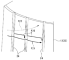
- FIG. 7 is a partially enlarged view of the vertical rib 24.
- vertical ribs 24 extending in the vertical direction (axial direction of the spindle shaft 33) are provided in the circumferential direction. A plurality of lines are provided throughout.
- 24 vertical ribs 24 each having a height and a width of 0.8 mm from the inner surface are formed at equal intervals in the circumferential direction. The length of the vertical rib 24 is determined to be the same as or slightly longer than the height of the rotor unit 21.
- these vertical ribs 24 are for capturing and agglomerating the separated oil flowing in the circumferential direction along the inner surface of the main body cover 22 so as to flow downward.
- a high-speed swirling flow is generated around the rotor unit 21 accordingly.
- a swirling flow as indicated by an arrow F21 in FIG. 7 is generated.
- the separated oil travels on the inner surface of the main body cover 22 along this swirling flow.
- the buoyancy which goes diagonally upward as shown by the arrow of F22 is also given to the oil which moves an inner surface.
- the trapped oil coalesces and coalesces with the subsequent oil. Since the self-weight is increased by the aggregation, the oil after the aggregation flows down along the vertical ribs 24 against the swirling flow. As a result, the amount of oil that rises on the swirling flow and is discharged together with the blow-by gas can be reduced, and the oil removal efficiency can be increased.
- the height of the vertical ribs 24 is set to 0.8 mm. However, if experimentally 0.5 to 1.0 mm, the oil can flow down after separation flowing in the circumferential direction. It was. Further, regarding the number of the vertical ribs 24 formed, even if the experiment was performed with 48, no significant difference was found in the effect. From this, it is considered that if the longitudinal ribs 24 are formed at intervals suitable for the speed of the swirling flow, the mixing of oil into the blow-by gas can be suppressed.
- a plurality of reinforcing ribs 56 are provided on the entire outer surface of the main body cover 22 in the circumferential direction. For this reason, with respect to the main body cover 22, necessary strength can be secured by the reinforcing rib 56. Therefore, regarding the vertical ribs 24, the degree of freedom in design can be increased. That is, it can be provided at a height or interval according to the speed of the swirling flow.
- the cylindrical rib 54 (guide rib) will be described.
- the cylindrical rib 54 is a circular ring provided inside the main body cover 22 and downwardly at a position below the pedestal 51 on which the PCV valve 28 is placed. It is a ridge.
- the diameter of the cylindrical rib 54 substantially matches the diameter of the rotor 31.
- the cylindrical rib 54 and the rotor 31 are concentric when viewed in the plane direction, and a predetermined clearance is defined between the lower edge of the cylindrical rib 54 and the upper outer periphery of the rotor 31.
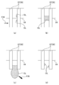
- the cylindrical rib 54 is provided with a guide claw 57 protruding downward from the lower edge of the cylindrical rib 54.
- the guide claw 57 is a protrusion for aggregating and dropping the oil captured by the cylindrical rib 54.
- the protruding length of the guide claw 57 is set slightly shorter than the clearance between the cylindrical rib 54 and the rotor 31. Thereby, the lower end of the guide claw 57 is positioned immediately above the outer peripheral edge of the upper end of the rotor 31.
- the guide claws 57 in the present embodiment are provided at intervals of 60 degrees in the circumferential direction. That is, a total of six guide claws 57 are provided.
- the guide claw 57 is formed by a small piece 58 having a downward arrow shape, in other words, a small piece 58 having a lower portion tapered like a wedge. It is configured.
- a pair of small piece 58 is attached side by side at predetermined intervals. This attachment interval is determined to be a size that allows the oil moving along the cylindrical rib 54 to be captured in the gap between the adjacent small pieces 58. For example, it is set to about 1 to 2 mm.
- the oil OL that has moved to the outer surface of the cylindrical rib 54 flows down the outer surface of the cylindrical rib 54 and moves to the lower end of the cylindrical rib 54. Then, as shown in FIGS. 10 and 11A, the oil OL that has moved to the lower end of the cylindrical rib 54 moves along the lower end of the cylindrical rib 54, as indicated by the arrow F24, in the small piece 58. It adheres to the windward surface. As time passes, the other oil OL also adheres to the surface of the small piece 58 and coalesces. For this reason, as shown in FIG. 11 (b), the adhered oil OL is held by the surface tension in the gap formed by each small piece 58.
- the lower end of the guide claw 57 is positioned immediately above the upper end of the outer periphery of the rotor 31. For this reason, the airflow generated by the rotation of the rotor 31 acts on the protruding portion of the guide claw 57 from the cylindrical rib 54. By receiving this air flow, the oil OL that has flowed down the guide claw 57 is blown off in the outer peripheral direction as droplets. As a result, the oil after separation becomes mist and hardly returns to the blow-by gas, and the oil removal efficiency can be improved.
- the cylindrical ribs 54 are provided, the separated oil that has not been captured by the vertical ribs 24 can be captured by the guide ribs. Thereby, oil removal efficiency can further be improved. Further, since the guide rib 57 is provided on the cylindrical rib 54, the oil that has reached the lower end of the cylindrical rib 54 can be easily aggregated.
- the guide claw 57 is composed of a pair of small pieces 58 arranged with a predetermined gap therebetween, the oil caught by the guide ribs can be caught in the gap between the adjacent small pieces 58, and the oil is aggregated. It can be done easily.
- the small piece 58 is formed in a tapered shape downward, the holding force of the oil in the guide claw 57 can be reduced as it goes downward. Thereby, the oil captured and aggregated by the guide claw 57 moves downward by its own weight, so that the oil can be easily detached from the guide claw 57.
- the projecting portion of the guide claw 57 is disposed within the flow range of the wind (swirl flow) generated by the rotation of the rotor 31 (separation disk 34), the separation of the oil from the guide claw 57 is separated.
- the wind generated at 34 can assist. Thereby, oil can be more easily detached from the guide claw 57.
- the height and number of the vertical ribs 24 are not limited to the example of the embodiment. Moreover, as long as it extends in the up-down direction, it may not be linear. For example, a spiral rib in which the oil that has received the swirling flow is guided obliquely downward may be used.
- the housing 11 may have a three-piece configuration of an upper part, an intermediate part, and a lower part, and the vertical ribs 24 may be provided in the intermediate part.
- the number of guide claws 57 is not limited to six. Further, the number of small pieces 58 constituting the guide claw 57 is not limited to two. There may be three or more, or one. It is more preferable that the guide claw 57 is composed of a plurality of small pieces 58 because oil can be captured in the gaps.
- the protruding portion of the small piece 58 may not have a tapered shape.
- the tapered portion is tapered as in the above-described embodiment, the holding force by the guide claw 57 is increased due to the increase in the weight of the oil and the downward movement. Becomes smaller. As a result, the oil can be made to drop and be easily separated.
- the lower end of the guide claw 57 is disposed immediately above the outer peripheral upper end of the rotor 31, it may be in a range in which the wind from the rotor 31 circulates. This is because the oil can be made to drop off and easily removed.
Abstract
Description
Claims (6)
- 処理対象ガスに含まれるミスト状オイルを分離するオイルセパレータであって、
スピンドルと共に回転可能に設けられ、前記スピンドルの軸線方向に積層された複数枚の分離ディスクと、
前記スピンドルにおける前記分離ディスクよりも下側の周面から突設され、噴射孔からオイルを噴射させることで軸線を中心に前記スピンドルを回転させるノズルと、
円筒状の側壁部を含んで構成され、前記スピンドル、前記分離ディスク、及び前記ノズルが収容される収容室を区画するハウジングとを有し、
前記側壁部の内表面に、上下方向に延びる縦リブを周方向に複数本形成したことを特徴とするオイルセパレータ。 - 前記ハウジングには、前記分離ディスクよりも上方の位置に、前記上側ケースの内表面に沿って平面視の中心側に向けて流れる流体を下向きに案内する円筒状の案内リブが設けられていることを特徴とする請求項1に記載のオイルセパレータ。
- 前記案内リブには、前記案内リブの下縁よりも下方に突出された誘導爪が設けられていることを特徴とする請求項2に記載のオイルセパレータ。
- 前記誘導爪は、所定の隙間を空けて配置された複数の小片によって構成されていることを特徴とする請求項3に記載のオイルセパレータ。
- 前記小片は、下方に向けて先細り形状に作成されていることを特徴とする請求項4に記載のオイルセパレータ。
- 前記誘導爪の突出部分を、前記分離ディスクの回転で発生される風の流通範囲内に配置したことを特徴とする請求項3から5の何れか1項に記載のオイルセパレータ。
Priority Applications (4)
| Application Number | Priority Date | Filing Date | Title |
|---|---|---|---|
| PCT/JP2014/054439 WO2015128928A1 (ja) | 2014-02-25 | 2014-02-25 | オイルセパレータ |
| JP2016504877A JP6336037B2 (ja) | 2014-02-25 | 2014-02-25 | オイルセパレータ |
| EP14883753.7A EP3112031A4 (en) | 2014-02-25 | 2014-02-25 | Oil separator |
| US15/121,672 US20170001133A1 (en) | 2014-02-25 | 2014-02-25 | Oil separator |
Applications Claiming Priority (1)
| Application Number | Priority Date | Filing Date | Title |
|---|---|---|---|
| PCT/JP2014/054439 WO2015128928A1 (ja) | 2014-02-25 | 2014-02-25 | オイルセパレータ |
Publications (1)
| Publication Number | Publication Date |
|---|---|
| WO2015128928A1 true WO2015128928A1 (ja) | 2015-09-03 |
Family
ID=54008300
Family Applications (1)
| Application Number | Title | Priority Date | Filing Date |
|---|---|---|---|
| PCT/JP2014/054439 WO2015128928A1 (ja) | 2014-02-25 | 2014-02-25 | オイルセパレータ |
Country Status (4)
| Country | Link |
|---|---|
| US (1) | US20170001133A1 (ja) |
| EP (1) | EP3112031A4 (ja) |
| JP (1) | JP6336037B2 (ja) |
| WO (1) | WO2015128928A1 (ja) |
Cited By (1)
| Publication number | Priority date | Publication date | Assignee | Title |
|---|---|---|---|---|
| WO2017175323A1 (ja) * | 2016-04-06 | 2017-10-12 | 東京濾器株式会社 | オイルセパレータ |
Families Citing this family (6)
| Publication number | Priority date | Publication date | Assignee | Title |
|---|---|---|---|---|
| CN108136303B (zh) | 2015-09-24 | 2021-05-07 | 康明斯过滤Ip公司 | 在过滤介质和旋转式滤芯的端盖之间使用机械密封 |
| WO2018236921A1 (en) | 2017-06-20 | 2018-12-27 | Cummins Filtration Ip, Inc. | CENTRIFUGAL SEPARATOR WITH AXIAL FLOW |
| FR3096275B1 (fr) | 2019-05-24 | 2021-06-18 | Safran Helicopter Engines | Pièce pour dégazeur centrifuge de turbomachine avec parois longitudinales adaptées |
| WO2021154392A1 (en) * | 2020-01-28 | 2021-08-05 | Cummins Filtration Inc. | Electric motor integrated rotating crankcase ventilation filter assemblies |
| US20220411073A1 (en) * | 2021-06-29 | 2022-12-29 | Hamilton Sundstrand Corporation | Centrifugal water collector with conical water scupper |
| KR102429726B1 (ko) * | 2022-03-10 | 2022-08-08 | (주) 삼진정밀 | 디스크 적층형 여과장치 |
Citations (7)
| Publication number | Priority date | Publication date | Assignee | Title |
|---|---|---|---|---|
| JPH04247251A (ja) * | 1991-01-31 | 1992-09-03 | Toshiba Corp | 固液分離装置 |
| JP2002239414A (ja) * | 2000-12-18 | 2002-08-27 | Fleetguard Inc | 使い捨て式の自己駆動型遠心分離機 |
| JP2005507310A (ja) * | 2001-11-01 | 2005-03-17 | アルファ ラヴァル コーポレイト アクチボラゲット | 液体と気体とを同時に浄化する装置 |
| JP2005515065A (ja) * | 2002-01-25 | 2005-05-26 | アルファ ラヴァル コーポレイト アクチボラゲット | 液体とガスとを同時に浄化する装置 |
| JP2005270964A (ja) * | 2004-02-16 | 2005-10-06 | Fleetguard Inc | 性能改善の特徴を備えたスピンオンフィルター |
| JP2009167812A (ja) * | 2008-01-10 | 2009-07-30 | Toyota Boshoku Corp | 遠心分離式オイルフィルタ |
| JP2013202449A (ja) * | 2012-03-27 | 2013-10-07 | Tlv Co Ltd | 気液分離器 |
Family Cites Families (23)
| Publication number | Priority date | Publication date | Assignee | Title |
|---|---|---|---|---|
| NL285656A (ja) * | 1961-11-22 | |||
| US6183407B1 (en) * | 1998-04-02 | 2001-02-06 | Alfa Laval Ab | Centrifugal separator having axially-extending, angled separation discs |
| US6110246A (en) * | 1998-07-23 | 2000-08-29 | Dreison International, Inc. | Air precleaner having stationary vanes and rotating impeller |
| US6017300A (en) * | 1998-08-19 | 2000-01-25 | Fleetguard, Inc. | High performance soot removing centrifuge with impulse turbine |
| SE515302C2 (sv) * | 1999-11-15 | 2001-07-09 | Alfa Laval Ab | Ett sätt och en apparat för rening av gas |
| SE517663C2 (sv) * | 2000-10-27 | 2002-07-02 | Alfa Laval Corp Ab | Centrifugalseparator för rening av ett gasformigt fluidum |
| SE0201982D0 (sv) * | 2002-06-24 | 2002-06-24 | Alfa Laval Corp Ab | Sätt att rena vevhusgas samt en gasreningsseparator |
| SE523676C2 (sv) * | 2002-09-04 | 2004-05-11 | Alfa Laval Corp Ab | Apparat för rening av gas |
| US7235177B2 (en) * | 2003-04-23 | 2007-06-26 | Fleetguard, Inc. | Integral air/oil coalescer for a centrifuge |
| US7258713B2 (en) * | 2004-08-27 | 2007-08-21 | Dreison International, Inc. | Inlet vane for centrifugal particle separator |
| SE529609C2 (sv) * | 2006-02-13 | 2007-10-02 | Alfa Laval Corp Ab | Centrifugalseparator |
| SE529611C2 (sv) * | 2006-02-13 | 2007-10-02 | Alfa Laval Corp Ab | Centrifugalseparator |
| US7338546B2 (en) * | 2006-04-19 | 2008-03-04 | Alfa Laval Corporate Ab | Centrifugal separator for cleaning gas generated by an internal combustion engine and a method for operating the same |
| SE530223C2 (sv) * | 2006-05-15 | 2008-04-01 | Alfa Laval Corp Ab | Centrifugalseparator |
| DE202007009913U1 (de) * | 2007-07-13 | 2008-11-20 | Hengst Gmbh & Co.Kg | Abscheider zum Abscheiden von Ölnebel aus dem Kurbelgehäuseentlüftungsgas einer Brennkraftmaschine und Brennkraftmaschine mit einem Abscheider |
| EP2020485B1 (de) * | 2007-07-31 | 2013-09-25 | Hengst GmbH & Co. KG | Ölnebelabscheider einer Brennkraftmaschine |
| DE202008014734U1 (de) * | 2008-11-06 | 2010-03-25 | Hengst Gmbh & Co.Kg | Zentrifugalabscheider |
| US20110011795A1 (en) * | 2009-07-15 | 2011-01-20 | Hoff William D | Fluid pressure driven centrifuge apparatus |
| US9194265B2 (en) * | 2010-01-27 | 2015-11-24 | Cummins Filtration Ip, Inc. | Rotating separator with housing preventing separated liquid carryover |
| DE102010002787B4 (de) * | 2010-03-11 | 2020-12-10 | Hengst Se | Ölnebelabscheider mit einem Ölrückführkanal mit Siphon und Brennkraftmaschine mit Ölnebelabscheider |
| US9987579B2 (en) * | 2013-03-28 | 2018-06-05 | Tokyo Roki Co., Ltd. | Oil separator |
| EP2944391A1 (en) * | 2014-05-13 | 2015-11-18 | Alfa Laval Corporate AB | Centrifugal separator |
| JP6511522B2 (ja) * | 2015-06-19 | 2019-05-15 | 東京濾器株式会社 | オイルセパレータ |
-
2014
- 2014-02-25 EP EP14883753.7A patent/EP3112031A4/en active Pending
- 2014-02-25 JP JP2016504877A patent/JP6336037B2/ja active Active
- 2014-02-25 WO PCT/JP2014/054439 patent/WO2015128928A1/ja active Application Filing
- 2014-02-25 US US15/121,672 patent/US20170001133A1/en not_active Abandoned
Patent Citations (7)
| Publication number | Priority date | Publication date | Assignee | Title |
|---|---|---|---|---|
| JPH04247251A (ja) * | 1991-01-31 | 1992-09-03 | Toshiba Corp | 固液分離装置 |
| JP2002239414A (ja) * | 2000-12-18 | 2002-08-27 | Fleetguard Inc | 使い捨て式の自己駆動型遠心分離機 |
| JP2005507310A (ja) * | 2001-11-01 | 2005-03-17 | アルファ ラヴァル コーポレイト アクチボラゲット | 液体と気体とを同時に浄化する装置 |
| JP2005515065A (ja) * | 2002-01-25 | 2005-05-26 | アルファ ラヴァル コーポレイト アクチボラゲット | 液体とガスとを同時に浄化する装置 |
| JP2005270964A (ja) * | 2004-02-16 | 2005-10-06 | Fleetguard Inc | 性能改善の特徴を備えたスピンオンフィルター |
| JP2009167812A (ja) * | 2008-01-10 | 2009-07-30 | Toyota Boshoku Corp | 遠心分離式オイルフィルタ |
| JP2013202449A (ja) * | 2012-03-27 | 2013-10-07 | Tlv Co Ltd | 気液分離器 |
Non-Patent Citations (1)
| Title |
|---|
| See also references of EP3112031A4 * |
Cited By (4)
| Publication number | Priority date | Publication date | Assignee | Title |
|---|---|---|---|---|
| WO2017175323A1 (ja) * | 2016-04-06 | 2017-10-12 | 東京濾器株式会社 | オイルセパレータ |
| CN108883424A (zh) * | 2016-04-06 | 2018-11-23 | 东京滤器株式会社 | 油分离器 |
| US20190091618A1 (en) * | 2016-04-06 | 2019-03-28 | Tokyo Roki Co., Ltd. | Oil separator |
| EP3441145A4 (en) * | 2016-04-06 | 2019-12-11 | Tokyo Roki Co., Ltd. | OIL SEPARATOR |
Also Published As
| Publication number | Publication date |
|---|---|
| JPWO2015128928A1 (ja) | 2017-03-30 |
| EP3112031A4 (en) | 2018-01-17 |
| US20170001133A1 (en) | 2017-01-05 |
| JP6336037B2 (ja) | 2018-06-06 |
| EP3112031A1 (en) | 2017-01-04 |
Similar Documents
| Publication | Publication Date | Title |
|---|---|---|
| JP6336037B2 (ja) | オイルセパレータ | |
| JP6069488B2 (ja) | オイルセパレータ | |
| JP6286530B2 (ja) | オイルセパレータ | |
| JP6268302B2 (ja) | オイルセパレータ | |
| JP6511522B2 (ja) | オイルセパレータ | |
| JP6255476B2 (ja) | オイルセパレータ | |
| WO2016046944A1 (ja) | オイルセパレータ用分離ディスク、オイルセパレータ用ローター、及びオイルセパレータ | |
| JP6480594B2 (ja) | ガスを浄化するための遠心分離器 | |
| WO2014155614A1 (ja) | オイルセパレータ | |
| JP6647391B2 (ja) | オイルセパレータ | |
| JP6934471B2 (ja) | オイルセパレータ | |
| JP6322715B2 (ja) | ミスト状オイルの分離方法、及び、オイルセパレータ | |
| WO2016035204A1 (ja) | オイルセパレータ | |
| JP6336038B2 (ja) | オイルセパレータ | |
| JP6726739B2 (ja) | 分離ディスク積層体 | |
| CN107073379B (zh) | 油雾的分离方法及油分离器 |
Legal Events
| Date | Code | Title | Description |
|---|---|---|---|
| 121 | Ep: the epo has been informed by wipo that ep was designated in this application |
Ref document number: 14883753 Country of ref document: EP Kind code of ref document: A1 |
|
| ENP | Entry into the national phase |
Ref document number: 2016504877 Country of ref document: JP Kind code of ref document: A |
|
| NENP | Non-entry into the national phase |
Ref country code: DE |
|
| WWE | Wipo information: entry into national phase |
Ref document number: 15121672 Country of ref document: US |
|
| REEP | Request for entry into the european phase |
Ref document number: 2014883753 Country of ref document: EP |
|
| WWE | Wipo information: entry into national phase |
Ref document number: 2014883753 Country of ref document: EP |