WO2015125585A1 - Système d'alimentation en gaz et station-service à hydrogène - Google Patents
Système d'alimentation en gaz et station-service à hydrogène Download PDFInfo
- Publication number
- WO2015125585A1 WO2015125585A1 PCT/JP2015/052578 JP2015052578W WO2015125585A1 WO 2015125585 A1 WO2015125585 A1 WO 2015125585A1 JP 2015052578 W JP2015052578 W JP 2015052578W WO 2015125585 A1 WO2015125585 A1 WO 2015125585A1
- Authority
- WO
- WIPO (PCT)
- Prior art keywords
- unit
- supply system
- gas supply
- gas
- housing
- Prior art date
Links
Images


Classifications
-
- F—MECHANICAL ENGINEERING; LIGHTING; HEATING; WEAPONS; BLASTING
- F17—STORING OR DISTRIBUTING GASES OR LIQUIDS
- F17C—VESSELS FOR CONTAINING OR STORING COMPRESSED, LIQUEFIED OR SOLIDIFIED GASES; FIXED-CAPACITY GAS-HOLDERS; FILLING VESSELS WITH, OR DISCHARGING FROM VESSELS, COMPRESSED, LIQUEFIED, OR SOLIDIFIED GASES
- F17C5/00—Methods or apparatus for filling containers with liquefied, solidified, or compressed gases under pressures
- F17C5/06—Methods or apparatus for filling containers with liquefied, solidified, or compressed gases under pressures for filling with compressed gases
-
- F—MECHANICAL ENGINEERING; LIGHTING; HEATING; WEAPONS; BLASTING
- F04—POSITIVE - DISPLACEMENT MACHINES FOR LIQUIDS; PUMPS FOR LIQUIDS OR ELASTIC FLUIDS
- F04B—POSITIVE-DISPLACEMENT MACHINES FOR LIQUIDS; PUMPS
- F04B41/00—Pumping installations or systems specially adapted for elastic fluids
- F04B41/02—Pumping installations or systems specially adapted for elastic fluids having reservoirs
-
- F—MECHANICAL ENGINEERING; LIGHTING; HEATING; WEAPONS; BLASTING
- F17—STORING OR DISTRIBUTING GASES OR LIQUIDS
- F17C—VESSELS FOR CONTAINING OR STORING COMPRESSED, LIQUEFIED OR SOLIDIFIED GASES; FIXED-CAPACITY GAS-HOLDERS; FILLING VESSELS WITH, OR DISCHARGING FROM VESSELS, COMPRESSED, LIQUEFIED, OR SOLIDIFIED GASES
- F17C5/00—Methods or apparatus for filling containers with liquefied, solidified, or compressed gases under pressures
- F17C5/002—Automated filling apparatus
- F17C5/007—Automated filling apparatus for individual gas tanks or containers, e.g. in vehicles
-
- F—MECHANICAL ENGINEERING; LIGHTING; HEATING; WEAPONS; BLASTING
- F17—STORING OR DISTRIBUTING GASES OR LIQUIDS
- F17C—VESSELS FOR CONTAINING OR STORING COMPRESSED, LIQUEFIED OR SOLIDIFIED GASES; FIXED-CAPACITY GAS-HOLDERS; FILLING VESSELS WITH, OR DISCHARGING FROM VESSELS, COMPRESSED, LIQUEFIED, OR SOLIDIFIED GASES
- F17C2205/00—Vessel construction, in particular mounting arrangements, attachments or identifications means
- F17C2205/01—Mounting arrangements
- F17C2205/0103—Exterior arrangements
- F17C2205/0111—Boxes
-
- F—MECHANICAL ENGINEERING; LIGHTING; HEATING; WEAPONS; BLASTING
- F17—STORING OR DISTRIBUTING GASES OR LIQUIDS
- F17C—VESSELS FOR CONTAINING OR STORING COMPRESSED, LIQUEFIED OR SOLIDIFIED GASES; FIXED-CAPACITY GAS-HOLDERS; FILLING VESSELS WITH, OR DISCHARGING FROM VESSELS, COMPRESSED, LIQUEFIED, OR SOLIDIFIED GASES
- F17C2205/00—Vessel construction, in particular mounting arrangements, attachments or identifications means
- F17C2205/01—Mounting arrangements
- F17C2205/0123—Mounting arrangements characterised by number of vessels
- F17C2205/013—Two or more vessels
- F17C2205/0134—Two or more vessels characterised by the presence of fluid connection between vessels
- F17C2205/0142—Two or more vessels characterised by the presence of fluid connection between vessels bundled in parallel
-
- F—MECHANICAL ENGINEERING; LIGHTING; HEATING; WEAPONS; BLASTING
- F17—STORING OR DISTRIBUTING GASES OR LIQUIDS
- F17C—VESSELS FOR CONTAINING OR STORING COMPRESSED, LIQUEFIED OR SOLIDIFIED GASES; FIXED-CAPACITY GAS-HOLDERS; FILLING VESSELS WITH, OR DISCHARGING FROM VESSELS, COMPRESSED, LIQUEFIED, OR SOLIDIFIED GASES
- F17C2221/00—Handled fluid, in particular type of fluid
- F17C2221/01—Pure fluids
- F17C2221/012—Hydrogen
-
- F—MECHANICAL ENGINEERING; LIGHTING; HEATING; WEAPONS; BLASTING
- F17—STORING OR DISTRIBUTING GASES OR LIQUIDS
- F17C—VESSELS FOR CONTAINING OR STORING COMPRESSED, LIQUEFIED OR SOLIDIFIED GASES; FIXED-CAPACITY GAS-HOLDERS; FILLING VESSELS WITH, OR DISCHARGING FROM VESSELS, COMPRESSED, LIQUEFIED, OR SOLIDIFIED GASES
- F17C2223/00—Handled fluid before transfer, i.e. state of fluid when stored in the vessel or before transfer from the vessel
- F17C2223/01—Handled fluid before transfer, i.e. state of fluid when stored in the vessel or before transfer from the vessel characterised by the phase
- F17C2223/0107—Single phase
- F17C2223/0123—Single phase gaseous, e.g. CNG, GNC
-
- F—MECHANICAL ENGINEERING; LIGHTING; HEATING; WEAPONS; BLASTING
- F17—STORING OR DISTRIBUTING GASES OR LIQUIDS
- F17C—VESSELS FOR CONTAINING OR STORING COMPRESSED, LIQUEFIED OR SOLIDIFIED GASES; FIXED-CAPACITY GAS-HOLDERS; FILLING VESSELS WITH, OR DISCHARGING FROM VESSELS, COMPRESSED, LIQUEFIED, OR SOLIDIFIED GASES
- F17C2223/00—Handled fluid before transfer, i.e. state of fluid when stored in the vessel or before transfer from the vessel
- F17C2223/03—Handled fluid before transfer, i.e. state of fluid when stored in the vessel or before transfer from the vessel characterised by the pressure level
- F17C2223/033—Small pressure, e.g. for liquefied gas
-
- F—MECHANICAL ENGINEERING; LIGHTING; HEATING; WEAPONS; BLASTING
- F17—STORING OR DISTRIBUTING GASES OR LIQUIDS
- F17C—VESSELS FOR CONTAINING OR STORING COMPRESSED, LIQUEFIED OR SOLIDIFIED GASES; FIXED-CAPACITY GAS-HOLDERS; FILLING VESSELS WITH, OR DISCHARGING FROM VESSELS, COMPRESSED, LIQUEFIED, OR SOLIDIFIED GASES
- F17C2225/00—Handled fluid after transfer, i.e. state of fluid after transfer from the vessel
- F17C2225/01—Handled fluid after transfer, i.e. state of fluid after transfer from the vessel characterised by the phase
- F17C2225/0107—Single phase
- F17C2225/0123—Single phase gaseous, e.g. CNG, GNC
-
- F—MECHANICAL ENGINEERING; LIGHTING; HEATING; WEAPONS; BLASTING
- F17—STORING OR DISTRIBUTING GASES OR LIQUIDS
- F17C—VESSELS FOR CONTAINING OR STORING COMPRESSED, LIQUEFIED OR SOLIDIFIED GASES; FIXED-CAPACITY GAS-HOLDERS; FILLING VESSELS WITH, OR DISCHARGING FROM VESSELS, COMPRESSED, LIQUEFIED, OR SOLIDIFIED GASES
- F17C2225/00—Handled fluid after transfer, i.e. state of fluid after transfer from the vessel
- F17C2225/03—Handled fluid after transfer, i.e. state of fluid after transfer from the vessel characterised by the pressure level
- F17C2225/036—Very high pressure, i.e. above 80 bars
-
- F—MECHANICAL ENGINEERING; LIGHTING; HEATING; WEAPONS; BLASTING
- F17—STORING OR DISTRIBUTING GASES OR LIQUIDS
- F17C—VESSELS FOR CONTAINING OR STORING COMPRESSED, LIQUEFIED OR SOLIDIFIED GASES; FIXED-CAPACITY GAS-HOLDERS; FILLING VESSELS WITH, OR DISCHARGING FROM VESSELS, COMPRESSED, LIQUEFIED, OR SOLIDIFIED GASES
- F17C2227/00—Transfer of fluids, i.e. method or means for transferring the fluid; Heat exchange with the fluid
- F17C2227/01—Propulsion of the fluid
- F17C2227/0128—Propulsion of the fluid with pumps or compressors
- F17C2227/0157—Compressors
- F17C2227/0164—Compressors with specified compressor type, e.g. piston or impulsive type
-
- F—MECHANICAL ENGINEERING; LIGHTING; HEATING; WEAPONS; BLASTING
- F17—STORING OR DISTRIBUTING GASES OR LIQUIDS
- F17C—VESSELS FOR CONTAINING OR STORING COMPRESSED, LIQUEFIED OR SOLIDIFIED GASES; FIXED-CAPACITY GAS-HOLDERS; FILLING VESSELS WITH, OR DISCHARGING FROM VESSELS, COMPRESSED, LIQUEFIED, OR SOLIDIFIED GASES
- F17C2227/00—Transfer of fluids, i.e. method or means for transferring the fluid; Heat exchange with the fluid
- F17C2227/03—Heat exchange with the fluid
- F17C2227/0337—Heat exchange with the fluid by cooling
- F17C2227/0341—Heat exchange with the fluid by cooling using another fluid
- F17C2227/0348—Water cooling
-
- F—MECHANICAL ENGINEERING; LIGHTING; HEATING; WEAPONS; BLASTING
- F17—STORING OR DISTRIBUTING GASES OR LIQUIDS
- F17C—VESSELS FOR CONTAINING OR STORING COMPRESSED, LIQUEFIED OR SOLIDIFIED GASES; FIXED-CAPACITY GAS-HOLDERS; FILLING VESSELS WITH, OR DISCHARGING FROM VESSELS, COMPRESSED, LIQUEFIED, OR SOLIDIFIED GASES
- F17C2227/00—Transfer of fluids, i.e. method or means for transferring the fluid; Heat exchange with the fluid
- F17C2227/03—Heat exchange with the fluid
- F17C2227/0337—Heat exchange with the fluid by cooling
- F17C2227/0341—Heat exchange with the fluid by cooling using another fluid
- F17C2227/0355—Heat exchange with the fluid by cooling using another fluid in a closed loop
-
- F—MECHANICAL ENGINEERING; LIGHTING; HEATING; WEAPONS; BLASTING
- F17—STORING OR DISTRIBUTING GASES OR LIQUIDS
- F17C—VESSELS FOR CONTAINING OR STORING COMPRESSED, LIQUEFIED OR SOLIDIFIED GASES; FIXED-CAPACITY GAS-HOLDERS; FILLING VESSELS WITH, OR DISCHARGING FROM VESSELS, COMPRESSED, LIQUEFIED, OR SOLIDIFIED GASES
- F17C2227/00—Transfer of fluids, i.e. method or means for transferring the fluid; Heat exchange with the fluid
- F17C2227/03—Heat exchange with the fluid
- F17C2227/0367—Localisation of heat exchange
- F17C2227/0388—Localisation of heat exchange separate
-
- F—MECHANICAL ENGINEERING; LIGHTING; HEATING; WEAPONS; BLASTING
- F17—STORING OR DISTRIBUTING GASES OR LIQUIDS
- F17C—VESSELS FOR CONTAINING OR STORING COMPRESSED, LIQUEFIED OR SOLIDIFIED GASES; FIXED-CAPACITY GAS-HOLDERS; FILLING VESSELS WITH, OR DISCHARGING FROM VESSELS, COMPRESSED, LIQUEFIED, OR SOLIDIFIED GASES
- F17C2227/00—Transfer of fluids, i.e. method or means for transferring the fluid; Heat exchange with the fluid
- F17C2227/04—Methods for emptying or filling
- F17C2227/041—Methods for emptying or filling vessel by vessel
-
- F—MECHANICAL ENGINEERING; LIGHTING; HEATING; WEAPONS; BLASTING
- F17—STORING OR DISTRIBUTING GASES OR LIQUIDS
- F17C—VESSELS FOR CONTAINING OR STORING COMPRESSED, LIQUEFIED OR SOLIDIFIED GASES; FIXED-CAPACITY GAS-HOLDERS; FILLING VESSELS WITH, OR DISCHARGING FROM VESSELS, COMPRESSED, LIQUEFIED, OR SOLIDIFIED GASES
- F17C2250/00—Accessories; Control means; Indicating, measuring or monitoring of parameters
- F17C2250/04—Indicating or measuring of parameters as input values
- F17C2250/0404—Parameters indicated or measured
- F17C2250/043—Pressure
-
- F—MECHANICAL ENGINEERING; LIGHTING; HEATING; WEAPONS; BLASTING
- F17—STORING OR DISTRIBUTING GASES OR LIQUIDS
- F17C—VESSELS FOR CONTAINING OR STORING COMPRESSED, LIQUEFIED OR SOLIDIFIED GASES; FIXED-CAPACITY GAS-HOLDERS; FILLING VESSELS WITH, OR DISCHARGING FROM VESSELS, COMPRESSED, LIQUEFIED, OR SOLIDIFIED GASES
- F17C2250/00—Accessories; Control means; Indicating, measuring or monitoring of parameters
- F17C2250/04—Indicating or measuring of parameters as input values
- F17C2250/0404—Parameters indicated or measured
- F17C2250/0447—Composition; Humidity
- F17C2250/0452—Concentration of a product
-
- F—MECHANICAL ENGINEERING; LIGHTING; HEATING; WEAPONS; BLASTING
- F17—STORING OR DISTRIBUTING GASES OR LIQUIDS
- F17C—VESSELS FOR CONTAINING OR STORING COMPRESSED, LIQUEFIED OR SOLIDIFIED GASES; FIXED-CAPACITY GAS-HOLDERS; FILLING VESSELS WITH, OR DISCHARGING FROM VESSELS, COMPRESSED, LIQUEFIED, OR SOLIDIFIED GASES
- F17C2250/00—Accessories; Control means; Indicating, measuring or monitoring of parameters
- F17C2250/07—Actions triggered by measured parameters
- F17C2250/072—Action when predefined value is reached
- F17C2250/075—Action when predefined value is reached when full
-
- F—MECHANICAL ENGINEERING; LIGHTING; HEATING; WEAPONS; BLASTING
- F17—STORING OR DISTRIBUTING GASES OR LIQUIDS
- F17C—VESSELS FOR CONTAINING OR STORING COMPRESSED, LIQUEFIED OR SOLIDIFIED GASES; FIXED-CAPACITY GAS-HOLDERS; FILLING VESSELS WITH, OR DISCHARGING FROM VESSELS, COMPRESSED, LIQUEFIED, OR SOLIDIFIED GASES
- F17C2265/00—Effects achieved by gas storage or gas handling
- F17C2265/06—Fluid distribution
- F17C2265/065—Fluid distribution for refueling vehicle fuel tanks
-
- F—MECHANICAL ENGINEERING; LIGHTING; HEATING; WEAPONS; BLASTING
- F17—STORING OR DISTRIBUTING GASES OR LIQUIDS
- F17C—VESSELS FOR CONTAINING OR STORING COMPRESSED, LIQUEFIED OR SOLIDIFIED GASES; FIXED-CAPACITY GAS-HOLDERS; FILLING VESSELS WITH, OR DISCHARGING FROM VESSELS, COMPRESSED, LIQUEFIED, OR SOLIDIFIED GASES
- F17C2270/00—Applications
- F17C2270/01—Applications for fluid transport or storage
- F17C2270/0134—Applications for fluid transport or storage placed above the ground
- F17C2270/0139—Fuel stations
-
- Y—GENERAL TAGGING OF NEW TECHNOLOGICAL DEVELOPMENTS; GENERAL TAGGING OF CROSS-SECTIONAL TECHNOLOGIES SPANNING OVER SEVERAL SECTIONS OF THE IPC; TECHNICAL SUBJECTS COVERED BY FORMER USPC CROSS-REFERENCE ART COLLECTIONS [XRACs] AND DIGESTS
- Y02—TECHNOLOGIES OR APPLICATIONS FOR MITIGATION OR ADAPTATION AGAINST CLIMATE CHANGE
- Y02E—REDUCTION OF GREENHOUSE GAS [GHG] EMISSIONS, RELATED TO ENERGY GENERATION, TRANSMISSION OR DISTRIBUTION
- Y02E60/00—Enabling technologies; Technologies with a potential or indirect contribution to GHG emissions mitigation
- Y02E60/30—Hydrogen technology
- Y02E60/32—Hydrogen storage
-
- Y—GENERAL TAGGING OF NEW TECHNOLOGICAL DEVELOPMENTS; GENERAL TAGGING OF CROSS-SECTIONAL TECHNOLOGIES SPANNING OVER SEVERAL SECTIONS OF THE IPC; TECHNICAL SUBJECTS COVERED BY FORMER USPC CROSS-REFERENCE ART COLLECTIONS [XRACs] AND DIGESTS
- Y02—TECHNOLOGIES OR APPLICATIONS FOR MITIGATION OR ADAPTATION AGAINST CLIMATE CHANGE
- Y02E—REDUCTION OF GREENHOUSE GAS [GHG] EMISSIONS, RELATED TO ENERGY GENERATION, TRANSMISSION OR DISTRIBUTION
- Y02E70/00—Other energy conversion or management systems reducing GHG emissions
- Y02E70/30—Systems combining energy storage with energy generation of non-fossil origin
-
- Y—GENERAL TAGGING OF NEW TECHNOLOGICAL DEVELOPMENTS; GENERAL TAGGING OF CROSS-SECTIONAL TECHNOLOGIES SPANNING OVER SEVERAL SECTIONS OF THE IPC; TECHNICAL SUBJECTS COVERED BY FORMER USPC CROSS-REFERENCE ART COLLECTIONS [XRACs] AND DIGESTS
- Y02—TECHNOLOGIES OR APPLICATIONS FOR MITIGATION OR ADAPTATION AGAINST CLIMATE CHANGE
- Y02P—CLIMATE CHANGE MITIGATION TECHNOLOGIES IN THE PRODUCTION OR PROCESSING OF GOODS
- Y02P90/00—Enabling technologies with a potential contribution to greenhouse gas [GHG] emissions mitigation
- Y02P90/45—Hydrogen technologies in production processes
Definitions
- the present invention relates to a gas supply system and a hydrogen station.
- Patent Document 1 discloses a hydrogen compression apparatus used in a hydrogen station.
- a hydrogen compression apparatus main body, a compressor drive motor, a gas cooler, and the like are installed on a common base.
- the hydrogen gas that has been stepped up to a predetermined pressure by the hydrogen compressor is temporarily stored in the pressure accumulator unit.
- a dispenser equipped with an adapter adapted to the supply port of the fuel cell vehicle is connected to the pressure accumulator unit.
- the hydrogen station disclosed in Patent Document 2 includes a first support, a compressor, a first pressure accumulator, a dispenser, a heat exchanger that cools hydrogen gas supplied to the dispenser, and a first And an extension unit connection branch line.
- the compressor, the first pressure accumulator, the heat exchanger, and the dispenser are disposed on the first support base.
- the first expansion unit connection branch line is connected to a second pressure accumulator constituting the first expansion pressure accumulator unit (expansion pressure accumulator unit).
- An object of the present invention is to reduce the installation area of the gas supply system.
- the present invention relates to a gas supply system that supplies gas to a filling facility that fills a tank mounting device with a gas, and includes a drive unit and a compressor unit that is driven by the drive unit and compresses the gas.
- a pressure accumulator unit having a plurality of pressure accumulators and storing gas discharged from the compressor unit; a precool system for cooling gas flowing into the filling facility from the pressure accumulator unit; and at least one of the precool systems
- a rectangular parallelepiped housing that accommodates the compressor unit and the accumulator unit, and the compressor unit is disposed in the housing in a state where the compression unit is located above the driving unit. And at least a part of the precooling system is disposed above the pressure accumulator unit on the side of the compressor unit. It is a gas supply system.
- the present invention is also a gas supply system that supplies gas to a filling facility that fills a tank mounting device with a gas, and includes a drive unit and a compressor that is driven by the drive unit and compresses the gas.
- a pressure accumulator unit that has a unit, a plurality of pressure accumulators, and stores gas discharged from the compressor unit; a precool system that cools gas that flows into the filling facility from the pressure accumulator unit; and the precool system.
- a rectangular parallelepiped housing that houses the compressor unit and the pressure accumulator unit, and the pressure accumulator unit is located on the side of the compressor unit, or below the pressure accumulator unit or It is a gas supply system in which the at least part of the precool system is positioned at least above one of the compressor units.
- FIG. 1 is a view showing a hydrogen station 10 according to the first embodiment of the present invention.
- the hydrogen station 10 includes a gas supply system 2 and a dispenser 11 that is a filling facility.
- the gas supply system 2 supplies hydrogen gas to the dispenser 11.
- the dispenser 11 fills the vehicle 9 as a tank mounting device with hydrogen gas.
- the vehicle 9 is a fuel cell vehicle, for example.
- the gas supply system 2 includes a gas flow path 20, a compressor unit 21, a gas cooling unit 22, a pressure accumulator unit 23, a precool system 24, a housing 4 indicated by a two-dot chain line, a control unit 29, Is provided.
- the compressor unit 21, a part of the gas cooling unit 22, and the accumulator unit 23 are disposed on the gas flow path 20. Hydrogen gas flows in the gas flow path 20 toward the dispenser 11.
- the control unit 29 controls the compressor unit 21, the accumulator unit 23, and the precool system 24. Most of equipment of the gas supply system 2 is accommodated in the housing 4 (details will be
- the compressor unit 21 is a reciprocating compressor, and includes a drive unit 211 and a compression unit 212.
- the compression unit 212 includes a piston and a cylinder, and the piston is driven by the power of the drive unit 211 to compress the gas in the cylinder.
- the number of compression units 212 is five.
- the gas cooling unit 22 cools the hydrogen gas discharged from the compression unit 212.
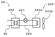
- FIG. 2 is a diagram showing the configuration of the gas cooling unit 22.
- the gas cooling unit 22 includes a cooling water passage 220 filled with cooling water that is a cooling fluid, a cooling water pump 221, a gas cooler 222, and a heat exhausting unit 223.
- the gas cooler 222 is a microchannel heat exchanger.
- the gas flow path 20 shown in FIGS. 1 and 2 is connected to the gas cooler 222.
- the exhaust heat unit 223 includes a heat exchanger 223a and a fan 223b. In the cooling water flow path 220, a cooling water pump 221, a gas cooler 222, and a heat exchanger 223a of the exhaust heat unit 223 are arranged.
- the hydrogen gas in the gas flow path 20 is cooled by heat exchange between the hydrogen gas discharged from the discharge unit of the compression unit 212 and the cooling water in the gas cooler 222.
- the cooling water that has absorbed heat flows into the heat exchanger 223a of the exhaust heat unit 223 and is cooled by the air flow generated by the fan 223b.
- the cooled cooling water is sent again to the gas cooler 222 by the cooling water pump 221.
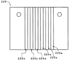
- FIG. 3 is a schematic view of the gas cooler 222.
- the gas cooler 222 includes a plurality of first plates 224 and a plurality of second plates 225.
- the gas cooler 222 is a stacked body in which the first plates 224 and the second plates 225 are alternately stacked.
- the plates 224 and 225 adjacent to each other are joined by diffusion joining.
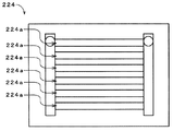
- FIG. 4 is a plan view of the first plate 224.
- a plurality of gas passages 224a through which hydrogen gas flows are formed in the first plate 224.
- FIG. 5 is a plan view of the second plate 225.
- a plurality of cooling flow paths 225a through which cooling water flows are formed in the second plate 225.
- Each pressure accumulator 231 stores hydrogen gas discharged from the compressor unit 21.
- the precool system 24 includes a refrigerator 3 and a brine circuit 5.
- the brine circuit 5 includes a brine flow path 240, a brine pump 241, and a precool heat exchanger 242 that is a microchannel heat exchanger.
- the brine circuit 5 may be provided with an unillustrated brine tank for storing brine.
- the brine flow path 240 is filled with brine, and a brine pump 241, a precool heat exchanger 242 and the refrigerator 3 are arranged.
- the hydrogen gas just before being charged from the dispenser 11 to the vehicle 9 is cooled by heat exchange between the hydrogen gas and the brine in the precool heat exchanger 242.
- the brine that has absorbed heat flows into the refrigerator 3 and is cooled.
- the cooled brine is sent again to the precool heat exchanger 242 by the brine pump 241.
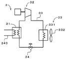
- FIG. 6 is a diagram showing the configuration of the refrigerator 3.
- the refrigerator 3 includes a refrigerant flow path 30, an evaporation unit 31, a refrigerant compression unit 32, a condensing unit 33, and an expansion unit 34.
- the refrigerant flow path 30 is filled with a refrigerant, and an evaporation unit 31, a refrigerant compression unit 32, a condensation unit 33, and an expansion unit 34 are arranged.
- the evaporation part 31 is connected to the brine flow path 240 shown in FIG. 1 and FIG. In the evaporation unit 31, the brine and the refrigerant exchange heat, thereby cooling the brine and evaporating the refrigerant.
- the condensing unit 33 includes a heat exchanger 331 through which a refrigerant flows and a fan 332.
- the refrigerant that has flowed into the heat exchanger 331 from the refrigerant compressor 32 is radiated and condensed by the air flow generated by the fan 332.
- the expansion unit 34 expands the refrigerant that has flowed out of the condensation unit 33, and the expanded refrigerant flows into the evaporation unit 31.
- the brine is cooled by a so-called heat pump cycle.
- the hydrogen gas sent from a gas supply source (not shown) is compressed in advance by the compressor unit 21 and cooled by the gas cooling unit 22. It is stored in the pressure accumulator unit 23.
- hydrogen gas is supplied from the pressure accumulator unit 23 to the dispenser 11, and the dispenser 11 fills the vehicle 9 with hydrogen gas according to a predetermined filling protocol.
- hydrogen gas is delivered from the two pressure accumulators 231 (for example, the two pressure accumulators 231 on the upper side in FIG. 1).
- the dispenser 11 indirectly measures the pressure in the vehicle 9 and determines that the pressure difference between the vehicle 9 and the two pressure accumulators 231a is equal to or less than a predetermined value, the dispenser 11 sends the pressure from the pressure accumulator 231a to the gas supply system 2. Send an instruction to stop the delivery of hydrogen gas.
- the gas supply system 2 opens another pressure accumulator 231 (for example, the third pressure accumulator 231 from the top in FIG. 1).
- hydrogen gas is sent from the pressure accumulator 231 to the dispenser 11.
- the reference numeral “231b” is attached.
- the pressure difference between the dispenser 11 (or the pressure accumulator 231b) and the vehicle 9 is recovered, and the flow rate of hydrogen gas charged into the vehicle 9 is ensured.
- the gas supply system 2 sends out hydrogen gas from the pressure accumulator 231b. Is opened, and another pressure accumulator (accumulator located on the lower side in FIG. 1) is opened. Thereby, hydrogen gas is sent out from the other accumulator. Thereby, the pressure difference between the dispenser 11 and the vehicle 9 is ensured, and a sufficient amount of hydrogen gas is filled.
- the supply of hydrogen gas from the gas supply system 2 is stopped.
- two pressure accumulators 231a among the four pressure accumulators 231 are used in the low pressure region (for example, 0 MPa to 40 MPa) of the tank of the vehicle 9, and the medium pressure region (40 MPa to 60 MPa). Another one pressure accumulator 231b is used, and another one pressure accumulator is further used in the high pressure region (60 MPa to 70 MPa).
- the gas supply system 2 switches the pressure accumulator 231 in accordance with the three pressure regions of the vehicle 9, whereby the dispenser 11 can efficiently fill the hydrogen gas according to the filling protocol.
- the two accumulators 231a are used in the low pressure region where the required flow rate of hydrogen gas is higher than that in the intermediate pressure region and the high pressure region, the flow rate of hydrogen gas is higher than when only one accumulator is used. Secured. For this reason, even if the pressure accumulator 231a is downsized, the vehicle 9 can be efficiently charged with hydrogen gas.
- the compressor unit 21 and the pressure accumulator unit 23 are accommodated in the housing 4 indicated by a two-dot chain line. Further, the casing 4 includes various devices of the precool system 24 excluding the precool heat exchanger 242 and the condensing unit 33 (see FIG. 6) of the refrigerator 3, and a gas cooling unit excluding the exhaust heat unit 223 shown in FIG. Twenty-two devices are also accommodated.
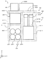
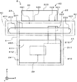
- FIG. 7 is a side view of the gas supply system 2.
- FIG. 8 is a view of the gas supply system 2 as viewed from the left side of FIG. 7 and 8, the housing 4 is indicated by a two-dot chain line. Further, only the main equipment of the gas supply system 2 is shown, and peripheral members such as piping are not shown. 7 and 8, the brine pump 241 of the precool system 24 shown in FIG. 1, the evaporation unit 31 of the refrigerator 3, the refrigerant compression unit 32 and the expansion unit 34 shown in FIG. 6 are shown by one rectangle, Reference numeral 24 is attached to the rectangle.
- the housing 4 has a rectangular parallelepiped shape.
- An opening 421 is formed in the upper part 42 of the housing 4.
- the opening 421 is closed by an openable / closable lid 422.
- the pressure accumulator unit 23 is disposed adjacent to the side of the compressor unit 21 in the Y direction (that is, the left-right direction in FIG. 7 and the direction perpendicular to the paper surface in FIG. 8).
- a part of the precool system 24 is arranged above the pressure accumulator unit 23.
- the Y direction in which the compressor unit 21 and the pressure accumulator unit 23 are arranged is referred to as “arrangement direction”.
- the X direction is a direction perpendicular to the arrangement direction in the horizontal plane (that is, a direction perpendicular to the paper surface of FIG. 7 and the left-right direction of FIG. 8).
- the Z direction is perpendicular to the X and Y directions and coincides with the direction of gravity.
- the Z direction is referred to as “vertical direction”.
- the compressor unit 21 and the accumulator unit 23 are explosion-proof specifications.
- a portion 491 in which the compressor unit 21 and the pressure accumulator unit 23 are arranged in the housing 4 is referred to as an “explosion-proof portion 491”.
- the explosion-proof section 491 the electrical equipment and instrumentation attached to the compressor unit 21 and the accumulator unit 23 are also explosion-proof specifications.
- the precool system 24 is a non-explosion-proof specification.
- a portion 492 in which the pre-cooling system 24 is disposed in the inside of the housing 4 is referred to as a “non-explosion-proof portion 492”.
- the control unit 29 is disposed in the non-explosion-proof unit 492.
- the electrical equipment and instrumentation that accompany the precool system 24 and the control part 29 are also non-explosion-proof specifications.
- a gas detection sensor (not shown) is arranged in the explosion-proof portion 491 and the non-explosion-proof portion 492 shown in FIGS. 7 and 8, and leakage of hydrogen gas in the housing 4 is managed.
- the compressor unit 21 is a so-called vertical type, and is arranged in the housing 4 in a state where the compression unit 212 is positioned above the drive unit 211 in the vertical direction. That is, in the compression unit 212, the piston reciprocates in the vertical direction in the cylinder. The entire compression unit 212 overlaps the opening 421 in the vertical direction. Thereby, when maintaining the compressor unit 21, the lid 422 can be opened and a part such as the compression unit 212 can be easily taken out of the housing 4 from the opening 421. Note that the exhaust heat unit 223 and the condensing unit 33 are separated from the opening 421. In the gas supply system 2, as long as a desired part of the compressor unit 21 can be taken out, only a part of the compression unit 212 may overlap the opening 421 in the vertical direction, and the entire compressor unit 21 may be opened in the opening 421. May overlap.
- each of the pressure accumulators 231 is a surface substantially perpendicular to the arrangement direction among the four side parts 411 and 412 of the casing 4 that rises perpendicular to the installation surface, that is, the direction in which the normal extends is parallel to the arrangement direction. Extends along a side 411 having a surface.
- the side portion 411 is referred to as a “first side portion 411”.
- the two side portions 412 having a plane parallel to the arrangement direction, that is, a plane perpendicular to the direction in which the pressure accumulator 231 extends are referred to as “second side portions 412”.
- the gas cooler 222 of the gas cooling unit 22 is fixed to the compression unit 212 of the compressor unit 21 in the explosion-proof unit 491.
- a cooling water pump 221 (see FIG. 2) is also disposed in the explosion-proof portion 491.
- the gas cooler 222 and the cooling water pump 221 are explosion-proof specifications.
- the heat exhausting part 223 is disposed on the upper part 42 of the housing 4.
- the brine pump 241 shown in FIG. 1, the evaporator 31 of the refrigerator 3, the refrigerant compressor 32 and the expander 34 shown in FIG. 6 are arranged in the non-explosion-proof part 492.
- the condensing unit 33 is disposed on the upper part 42 of the housing 4.
- the precool heat exchanger 242 is disposed in the vicinity of the dispenser 11 in FIG.
- the precool heat exchanger 242 may be disposed in the dispenser 11.
- the degree of freedom of installation location is improved as compared with the water-cooled type, and the upper part 42 of the housing 4 is effectively used. Can do.
- each device of the precool system 24 excluding the compressor unit 21, the gas cooling unit 22, the pressure accumulator unit 23, and the precool heat exchanger 242 is provided in the housing 4 or the upper portion 42 of the housing 4,
- the gas supply system 2 can be reduced in size.
- the hydrogen station 10 having the gas supply system 2 according to the first embodiment of the present invention has been described above.
- the compressor unit 21 is disposed in the casing 4 in a state in which the compressor unit 21 faces in the vertical direction, and the precool system 24 is disposed above the pressure accumulator unit 23.
- the area occupied by the compressor unit 21 can be reduced as compared with a so-called horizontal gas supply system in which the compressor unit is disposed in a horizontal plane.
- a space in this embodiment, a non-explosion-proof portion 492
- At least a part of the precool system 24 can be arranged in the space. Thereby, the installation area of the gas supply system 2 can be reduced, and the hydrogen station 10 can be downsized.
- the precool heat exchanger 242 is a microchannel heat exchanger
- the precool heat exchanger 242 can be downsized while ensuring the cooling efficiency of hydrogen gas, and as a result, other equipment of the precool system 24 can be obtained.
- the size can be reduced.
- many apparatus of the precool system 24 can be arrange
- the installation area of the gas supply system 2 can be further reduced by directly fixing the gas cooler 222 to the compression unit 212 of the compressor unit 21. . Since the exhaust heat unit 223 of the gas cooling unit 22 and the condensing unit 33 of the refrigerator 3 are arranged in the upper part 42 of the housing 4, the gas supply is performed as compared with the case where these members are arranged in a place other than the housing 4. The installation area of the system 2 can be further reduced.
- two four pressure accumulators 231 are arranged in the upper and lower stages. Compared to the case where the four pressure accumulators 231 are arranged side by side, the width in the arrangement direction of the pressure accumulator unit 23 can be suppressed, and the vertical direction compared to the case where the four pressure accumulators 231 are arranged in the vertical direction. Can be suppressed. Thus, in the gas supply system 2, the number of the pressure accumulators 231 can be ensured while suppressing the size of the pressure accumulators 231.
- the longitudinal direction of the pressure accumulator 231 extends along the first side portion 411 of the housing 4, the width in the arrangement direction of the housing 4 is prevented from becoming unnecessarily large, and the installation area of the gas supply system 2 is further increased. Can be small.
- a non-explosion-proof portion 492 is formed in the housing 4. Thereby, it is not necessary to make the precool system 24 and the control unit 29 explosion-proof, and it is possible to prevent an increase in the size of these devices and to significantly reduce the cost.
- FIG. 9 is a view showing a part of a hydrogen station 10a according to another example of the first embodiment.
- the dispenser 11 is attached to one of the second side portions 412 having a surface parallel to the arrangement direction of the housing 4.
- the precool heat exchanger 242 of the precool system 24 is disposed in the dispenser 11.
- the dispenser 11 is attached to the gas supply system 2, whereby the entire hydrogen station 10 a can be further downsized.
- the dispenser 11 may be slightly separated from the second side portion 412 if the dispenser 11 is disposed adjacent to the second side portion 412.
- the precool heat exchanger 242 may be disposed in the housing 4. Also in the gas supply system 2 shown in FIG. 1, the precool heat exchanger 242 can be arranged in the housing 4. In this case, all the devices of the compressor unit 21, the gas cooling unit 22, the pressure accumulator unit 23, and the precool system 24 are arranged in the casing 4 or the upper part 42 of the casing 4. A cover that covers the exhaust heat unit 223 and the condensing unit 33 may be attached to the upper part 42, and all devices may be arranged in the housing 4.
- the number of the pressure accumulators 231 is not necessarily four, and the number of the pressure accumulators 231 may be three when the flow rate of hydrogen gas is not so required in the low pressure region of the tank of the vehicle 9. . Further, when an arrangement space is secured in the explosion-proof portion 491, the number of the pressure accumulators 231 may be five or more.
- the short accumulator 231 is used, one accumulator group is formed by the plurality of accumulators 231, and the plurality of accumulator groups are arranged in the longitudinal direction of the accumulator 231, that is, in a horizontal plane. You may arrange
- a cooling fluid other than water may be used.
- the cooling water pump 221 may be disposed on the upper portion 42 of the housing 4.
- the dispenser 11 may be disposed adjacent to the first side portion 411.
- the gas supply system 2 may be used for filling hydrogen gas into a tank mounting device other than the vehicle.
- the gas supply system 2 may be used for supplying a gas other than hydrogen gas.
- Embodiment is a gas supply system which supplies gas to the filling equipment which fills a tank mounting apparatus with gas, Comprising: The compressor which has a drive part and the compression part which is driven by the said drive part and compresses gas
- a pressure accumulator unit that has a unit, a plurality of pressure accumulators, and stores gas discharged from the compressor unit; a precool system that cools gas that flows into the filling facility from the pressure accumulator unit; and the precool system.
- a rectangular parallelepiped housing that accommodates at least a part of the compressor unit and the pressure accumulator unit, and the compressor unit is located in an upper side of the drive unit in the housing. And at least a part of the precooling system is located above the pressure accumulator unit at the side of the compressor unit. It is arranged as a gas supply system.
- the installation area can be reduced.
- the plurality of pressure accumulators of the gas supply system may extend along a side portion of the housing having a surface substantially perpendicular to an arrangement direction that is a direction in which the compressor unit and the accumulator unit are arranged. .
- the installation area can be further reduced.
- the gas supply system may further include a gas cooler fixed to the compression unit and configured to exchange heat between the gas discharged from the compression unit and the cooling fluid.
- the gas cooler may be a stacked body in which a plurality of gas flow paths through which gas flows and a plurality of cooling flow paths through which the cooling fluid flows are alternately stacked. In this aspect, the installation area can be further reduced.
- the gas supply system may be provided with an exhaust heat unit that is disposed at an upper portion of the casing and cools the cooling fluid by an air flow.
- the installation area can be further reduced.
- the precool system may include a brine circuit that cools the gas flowing through the filling facility using brine and a refrigerator that cools the brine.
- the refrigerator includes an evaporation unit that evaporates the refrigerant to cool the brine, a refrigerant compression unit that compresses the refrigerant that has flowed out of the evaporation unit, and a refrigerant that is compressed in the refrigerant compression unit by the flow of air. You may provide the condensation part to condense and the expansion part which expands the refrigerant
- coolant compression part, and the said expansion part may be arrange
- the said condensation part may be arrange
- the condensing unit since the condensing unit has a structure that condenses the refrigerant by air cooling, the condensing unit can be disposed on the upper portion of the housing, and the installation area can be further reduced.
- the upper part of the casing of the gas supply system may have an opening, and in this case, the compressor unit may overlap the opening in the vertical direction. In this aspect, the compressor unit can be easily maintained.
- the pressure accumulator unit of the gas supply system may be formed by four pressure accumulators arranged two at the top and one at the bottom. In this aspect, the number of accumulators can be ensured while suppressing the size of the accumulator unit.
- two of the four pressure accumulators are used in the low pressure region of the tank in the tank mounting device, and other in the medium pressure region. One may be used, and the other may be used in the high pressure region. In this aspect, gas can be efficiently supplied to the tank mounting device.
- the compressor unit and the pressure accumulator unit are explosion-proof specifications
- the pre-cool system is non-explosion-proof specifications
- the at least part of the pre-cool system of the housing is disposed in a non-explosion-proof portion. May be.
- the control unit and the precool system can be reduced in size, and the cost can be reduced.
- Embodiment is a hydrogen station provided with the filling equipment and the gas supply system which supplies hydrogen gas to the said filling equipment, and the said filling equipment fills a tank mounting apparatus with hydrogen gas.
- the filling facility may be disposed adjacent to a side portion of the housing. In this aspect, the installation area of the whole apparatus including the gas supply system and the filling facility can be further reduced.
- a gas supply system 2 according to a second embodiment of the present invention will be described. Here, only the configuration different from the first embodiment will be described, and the description of the same configuration as the first embodiment will be omitted. 1 to 6 are also used as diagrams showing a supply system according to the second embodiment.
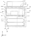
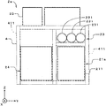
- FIG. 10 is a side view of the gas supply system 2.
- FIG. 11 is a view of the gas supply system 2 as viewed from the left side of FIG. 10 and 11, the housing 4 is indicated by a two-dot chain line. Further, only the main equipment of the gas supply system 2 is shown, and peripheral members such as piping are not shown. 10 and 11, the brine pump 241 of the precool system 24 shown in FIG. 1 and the evaporator 31 of the refrigerator 3, the refrigerant compressor 32 and the expander 34 shown in FIG. Reference numeral 24 is attached to the rectangle.
- the housing 4 has a rectangular parallelepiped shape.
- An opening 421 is formed in the upper portion 42 of the housing 4 and is closed by a lid 422 that can be opened and closed.
- a part of the pressure accumulator unit 23 and the pre-cooling system 24 is located on the side of the compressor unit 21 in the Y direction (that is, the direction left and right in FIG. 10 and perpendicular to the paper surface in FIG. 11). Adjacent to each other.
- the pressure accumulator unit 23 is located above the bottom of the housing 4, and the precool system 24 is located below the pressure accumulator unit 23.
- each of the pressure accumulators 231 is a surface substantially perpendicular to the arrangement direction among the four side parts 411 and 412 of the casing 4 that rises perpendicular to the installation surface, that is, the direction in which the normal extends is parallel to the arrangement direction. Extends along a side 411 having a surface.
- the side portion 411 is referred to as a “first side portion 411”.
- the two side portions 412 having a plane parallel to the arrangement direction, that is, a plane perpendicular to the direction in which the pressure accumulator 231 extends are referred to as “second side portions 412”.
- each pressure accumulator 231 has two projecting portions 232 projecting from the two second side portions 412 of the housing 4.
- Cover members 40 that cover the protrusions 232 are attached to the two second side portions 412 of the housing 4.
- the cover member 40 may be regarded as a part of the housing 4.
- the upper surface 401 of the cover member 40 is flush with the upper surface 420 of the housing 4.
- a work door (not shown) is installed below one or both cover members 40. Maintenance of the precool system 24 and the compressor unit 21 is performed by opening the work door.
- the gas cooler 222 of the gas cooling unit 22 is fixed to the compression unit 212 of the compressor unit 21 in the explosion-proof unit 491.
- the cooling water pump 221 (see FIG. 2) is also disposed in the explosion-proof portion 491.
- the gas cooler 222 and the cooling water pump 221 are explosion-proof specifications.
- the heat exhausting part 223 is disposed on the upper part 42 of the housing 4. In the gas supply system 2, since the air-cooled exhaust heat unit 223 is used, the degree of freedom of the installation location is improved compared to the water-cooled type, and the upper part 42 of the housing 4 can be used effectively.
- the brine pump 241 shown in FIG. 1 and the evaporator 31 of the refrigerator 3 and the refrigerant compressor 32 and the expander 34 shown in FIG. 6 are arranged in the non-explosion proof part 492 shown in FIGS. . These devices are located below the pressure accumulator unit 23.
- the brine circuit 5 may be disposed below the pressure accumulator unit 23 in the housing 4.
- the condensing unit 33 is disposed on the upper part 42 of the housing 4. Like the exhaust heat unit 223 of the gas cooling unit 22, the condensing unit 33 is also air-cooled, so that the degree of freedom of the installation location is improved and the upper part 42 of the housing 4 can be used effectively.
- a precool heat exchanger 242 of the brine circuit 5 shown in FIG. 1 is disposed outside the housing 4 and in the vicinity of the dispenser 11. In addition, it is also possible to arrange the precool heat exchanger 242 in the dispenser 11.
- each device of the precool system 24 excluding the compressor unit 21, the gas cooling unit 22, the pressure accumulator unit 23, and the precool heat exchanger 242 is provided in the housing 4 or the upper portion 42 of the housing 4.
- the hydrogen station 10 having the gas supply system 2 according to the second embodiment has been described above.
- the compressor unit 21, the pressure accumulator unit 23, and the precool system 24 (except for the precool heat exchanger 242 and the condensing unit 33), which are main devices, are arranged in the housing 4, and the housing A precool system 24 is arranged below the pressure accumulator unit 23 in the body 4.
- the installation area of the gas supply system 2 can be reduced, and the hydrogen station 10 can be downsized.
- the installation area can be further reduced by arranging the compressor unit 21 in the state in which the compressor unit 21 faces in the vertical direction.
- the three pressure accumulators 231 are arranged in parallel in the arrangement direction, so that the pressure accumulator 231 can be installed while suppressing the height of the gas supply system 2. Since the longitudinal direction of the pressure accumulator 231 is along the first side portion 411 of the housing 4, the width in the arrangement direction of the housing 4 is prevented from becoming unnecessarily large, and the installation area of the gas supply system 2 is further reduced. be able to. Moreover, when the pressure accumulators 231 are arranged in parallel in the horizontal direction, water can be efficiently sprayed to all the pressure accumulators 231 when the temperature of the pressure accumulators 231 rises.
- the pressure accumulator 231 since the pressure accumulator 231 has the protruding portion 232, the volume of the pressure accumulator 231 can be secured without increasing the installation area of the gas supply system 2.
- the area of the upper portion 42 of the housing 4 can be increased, and the installation area of the condensing unit 33 and the exhaust heat unit 223 can be increased.
- the work space can also be widened.
- the precool system 24 whose maintenance frequency is higher than that of the pressure accumulator unit 23 is disposed in the lower part of the gas supply system 2, so that the work load on the operator is reduced.
- the gas supply system 2 is prevented from being enlarged due to the explosion-proof specifications of these devices, and the cost is also greatly reduced. .
- FIG. 12 is a view showing a part of a hydrogen station 10a according to another example of the second embodiment.
- the dispenser 11 is attached to one of the second side portions 412 having a surface parallel to the arrangement direction of the housing 4.
- the precool heat exchanger 242 of the precool system 24 is disposed in the dispenser 11.
- the dispenser 11 is attached to the gas supply system 2, whereby the entire hydrogen station 10 a can be further downsized.
- the dispenser 11 may be slightly separated from the second side portion 412 if the dispenser 11 is disposed adjacent to the second side portion 412.
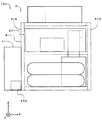
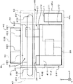
- FIG. 13 is a diagram showing still another example of the gas supply system 2 according to the second embodiment.
- the pressure accumulator unit 23 includes a connection portion 233 attached to the rear portion of the pressure accumulator 231 (that is, the end opposite to the hydrogen gas discharge portion).
- the connection part 233 includes an extraction pipe 233 a and a stop valve 233 b and is disposed in the housing 4.
- the pressure accumulator 231 can be connected in series to the other accumulator 81 for expansion through the connection portion 233.
- the pressure accumulator 81 is referred to as “additional pressure accumulator 81”.
- the connection part 233 is provided in the cover member 40 shown in FIG.
- the additional pressure accumulator 81 is preferably disposed below the cover member 40.
- the distance between the pressure accumulator 231 and the expansion pressure accumulator 81 can be shortened.
- the hydrogen gas in the expansion accumulator 81 corresponds when the amount of hydrogen gas in the accumulator 231 decreases. It is sent to the pressure accumulator 231.
- the pressure accumulator 81 can be easily added by providing the connection portion 233, and the amount of hydrogen gas stored in the hydrogen station 10 can be increased. As a result, hydrogen gas can be quickly supplied from many vehicles 9. Compared to the case where the expansion accumulator 81 is connected in series with the accumulator 231, the expansion accumulator 81 is connected in the middle of the flow path between the accumulator 231 and the dispenser 11 (see FIG. 1). Further, complicated control of the flow rate of hydrogen gas is prevented.
- FIG. 14 is a view showing a gas supply system 2a according to still another example of the second embodiment.
- the pressure accumulator unit 23 is located above the compressor unit 21a, and the precool system 24 is located on the side of the compressor unit 21a in the Y direction.
- the compressor unit 21a is a so-called horizontal type, and in FIG. 14, the compression unit is disposed on the back side of the paper surface from the drive unit 211.
- the other structure of the gas supply system 2a is the same as that of the gas supply system 2 according to the second embodiment, and the same components will be described with the same reference numerals.
- the pressure accumulator unit 23 and the compressor unit 21a are arranged along the first side portion 411 on the right side of FIG. More precisely, the longitudinal direction of the pressure accumulator 231 of the pressure accumulator unit 23 and the direction from the drive part 211 of the compressor unit 21a to the compression part are substantially parallel to the surface of the first side part 411.
- the pressure accumulator unit 23 is positioned above the compressor unit 21a, the installation area of the gas supply system 2a can be reduced, and the hydrogen station 10 can be downsized.
- the compressor unit 21a having a low height in the vertical direction, the height of the casing 4 is prevented from becoming high.
- a diaphragm-type compressor unit may be used as the compressor unit.
- the diaphragm type compressor unit may be a vertical type because the height in the vertical direction is suppressed compared to the piston type.
- the precool heat exchanger 242 may be disposed in the housing 4. Also in the gas supply system 2 shown in FIGS. 1 and 10, the precool heat exchanger 242 can be disposed in the housing 4. In this case, all the devices of the compressor unit 21, the gas cooling unit 22, the pressure accumulator unit 23, and the precool system 24 are arranged in the casing 4 or the upper part 42 of the casing 4. A cover that covers the exhaust heat unit 223 and the condensing unit 33 may be attached to the upper part 42, and all devices may be arranged in the housing 4. The same applies to the gas supply system 2a of FIG.
- a horizontal piston type compressor unit may be used, or a diaphragm type compressor unit may be used.
- the evaporation unit 31, the refrigerant compression unit 32, and the expansion unit 34 of the refrigerator 3 may be arranged in the space.
- the compressor unit 21, which is maintained more frequently than the refrigerator 3, below the refrigerator 3, it is possible to reduce the work load when performing maintenance.
- a brine tank is provided in the brine circuit 5, it may be arranged below the pressure accumulator unit 23.
- various devices of the precool system arranged in the housing 4 may be disposed below one of or both of the pressure accumulator unit 23 and the compressor unit 21.
- the gas cooler 222 may be a plate heat exchanger other than the microchannel heat exchanger as long as the gas cooler 222 is directly fixed to the compression unit 212.
- the number of the pressure accumulators 231 may be a number other than three.
- a cooling fluid other than water may be used as a cooling fluid for cooling the hydrogen gas.
- the cooling water pump 221 may be disposed on the upper portion 42 of the housing 4.
- the gas supply systems 2 and 2a may be used for filling hydrogen gas into tank mounting devices other than vehicles.
- the gas supply systems 2 and 2a may be used for supplying a gas other than hydrogen gas.
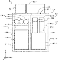
- the gas supply system 2b shows a gas supply system 2b according to still another example of the second embodiment.
- the dispenser 11 and the hydrogen receiving unit 28 are also arranged in the housing 4. Therefore, the gas supply system 2 b of this modification is configured as one package including the dispenser 11 and the hydrogen receiving unit 28.
- the compressor unit 21 is arranged in the X direction (the longitudinal direction of the pressure accumulator 231) in the housing 4 as in the gas supply system 2 of the second embodiment. ) Are arranged close to one end.
- the housing 4 is provided with cover members 40 on both sides in the X direction.
- An installation portion 46 for arranging the dispenser 11 is provided below the cover member 40 on the side close to the compressor unit 21.
- the housing 4 is positioned below the main body 44 between the pair of second side parts 412, the cover member 40 adjacent to the upper part of the second side part 412, and one cover member 40. It can be said that it has the installation part 46.
- the installation portion 46 includes a vertical portion 46 a extending downward from the outer end portion of the cover member 40 and a bottom portion 46 b extending in the X direction from the lower end portion of the vertical portion 46 a toward the second side portion 412.
- the dispenser 11 is located below the pressure accumulator unit 23 and is disposed on the bottom 46b.
- the hydrogen receiving unit 28 is disposed on the opposite side of the compressor unit 21 from the dispenser 11. More specifically, the hydrogen receiving unit 28 is disposed in the main body 44 close to the second side portion 412 on the side far from the compressor unit 21. As shown in FIG. 15, the hydrogen receiving unit 28 is located at a position displaced from the dispenser 11 and the pressure accumulator unit 23 in the Y direction.
- the hydrogen receiving unit 28 includes a pressure reducing valve (not shown) and various instrumentation.
- the pressure reducing valve depressurizes the hydrogen gas so as to receive the hydrogen gas from the outside through the gas flow path 20 into the compression section 212, and is disposed on the suction side of the compression section 212 in the gas flow path 20.
- the gas supply system is a gas supply system that supplies gas to a filling facility that fills a tank mounting device with gas, and is driven by the drive unit and the drive unit to compress the gas.
- a compressor unit having a compression unit; a plurality of pressure accumulators; a pressure accumulator unit that stores gas discharged from the compressor unit; and a precool that cools gas flowing from the pressure accumulator unit into the filling facility
- a rectangular parallelepiped housing that houses at least a part of the precool system, the compressor unit, and the accumulator unit.
- the accumulator unit is located on the side of the compressor unit, and the at least part of the precool system is located at least one of the lower side of the accumulator unit or the upper side of the compressor unit.
- the installation area of the gas supply system can be reduced.
- the gas supply system is a gas supply system that supplies gas to a filling facility that fills a tank mounting device with gas, and is driven by the drive unit and the drive unit to compress the gas.
- a compressor unit having a compression unit; a plurality of pressure accumulators; a pressure accumulator unit that stores gas discharged from the compressor unit; and a precool that cools gas flowing from the pressure accumulator unit into the filling facility
- a rectangular parallelepiped housing that houses at least a part of the precool system, the compressor unit, and the accumulator unit.
- the pressure accumulator unit is located above the compressor unit, and the pressure accumulator unit and the compressor unit are along one side of the casing.
- the installation area of the gas supply system can be reduced.
- the pressure accumulator unit may be positioned above the bottom of the casing, and in this case, the plurality of pressure accumulators may have protrusions that protrude from the casing, respectively. . Thereby, the volume of a pressure accumulator can be ensured, suppressing the installation area of a gas supply system.
- the gas supply system may further include a cover member that covers the protrusion, and in this case, the upper surface of the cover member may be flush with the upper surface of the housing. Thereby, the area of the upper part of a gas supply system can be enlarged.
- the plurality of pressure accumulators may be arranged in parallel in a horizontal plane. Thereby, many pressure accumulators can be provided while suppressing the height of the gas supply system.
- the pressure accumulator unit may further include a connecting portion provided in each of the plurality of pressure accumulators.
- each of the plurality of pressure accumulators is connected to the other through the connection portion.
- the accumulator may be connectable. Thereby, the amount of gas storage can be increased.
- the gas supply system may further include a gas cooler that is fixed to the compression unit and that exchanges heat between the gas discharged from the compression unit and the cooling fluid.
- the gas cooler includes a plurality of gases flowing through the gas.
- a laminated body in which a flow path and a plurality of cooling flow paths through which the cooling fluid flows are alternately stacked may be used. Thereby, an installation area can be made smaller.
- an exhaust heat unit may be provided that is disposed at an upper portion of the casing and cools the cooling fluid by an air flow. Thereby, an installation area can be made smaller.
- the pre-cooling system includes a brine circuit that cools the gas flowing through the filling facility using brine, and a refrigerator that cools the brine, and the refrigerator evaporates the refrigerant to brine.
- An expansion part that expands the gas, the evaporation part, the refrigerant compression part, and the expansion part may be disposed in the casing, and the condensing part may be disposed in an upper part of the casing. Since the condensing part has a structure that condenses the refrigerant by air cooling, the condensing part can be arranged on the upper part of the housing
- the plurality of pressure accumulators may extend along a side portion of the housing having a surface substantially perpendicular to an arrangement direction that is a direction in which the compressor unit and the accumulator unit are arranged. Good. Thereby, an installation area can be made smaller.
- an upper portion of the casing may have an opening, and the compressor unit may overlap the opening in the vertical direction. Thereby, maintenance of a compressor unit can be performed easily.
- the number of the plurality of pressure accumulators is three, and the plurality of pressure accumulators in a low pressure region of the tank in the tank mounting device when the filling facility fills the tank mounting device with gas.
- One may be used, the other may be used in the medium pressure region, and the other may be used in the high pressure region.
- the compressor unit and the pressure accumulator unit are explosion-proof specifications
- the pre-cool system is non-explosion-proof specifications
- the at least part of the pre-cool system of the housing is disposed in a non-explosion-proof portion. May be.
- the gas supply system may include a receiving unit that receives gas sucked into the compression unit from the outside.
- the filling equipment may be arranged on the opposite side of the receiving unit with respect to the compressor unit in the longitudinal direction of the pressure accumulator. Thereby, it can prevent that piping length becomes long about piping which connects a receiving unit and a compressor unit, and piping which connects filling equipment and a compressor unit.
- the hydrogen station according to the second embodiment includes a filling facility and a gas supply system that supplies hydrogen gas to the filling facility, and the filling facility fills the tank mounting device with the hydrogen gas.
- the filling facility may be disposed adjacent to a side portion of the housing. Thereby, the installation area of the whole apparatus containing a gas supply system and filling equipment can be made smaller.
Landscapes
- Engineering & Computer Science (AREA)
- Mechanical Engineering (AREA)
- General Engineering & Computer Science (AREA)
- Filling Or Discharging Of Gas Storage Vessels (AREA)
Abstract
Priority Applications (7)
| Application Number | Priority Date | Filing Date | Title |
|---|---|---|---|
| US15/116,382 US10634283B2 (en) | 2014-02-21 | 2015-01-29 | Gas supply system and hydrogen station |
| KR1020167025420A KR20160122814A (ko) | 2014-02-21 | 2015-01-29 | 가스 공급 시스템 및 수소 스테이션 |
| CA2938392A CA2938392C (fr) | 2014-02-21 | 2015-01-29 | Systeme d'alimentation en gaz et station-service a hydrogene |
| CN201580009615.3A CN106030186B (zh) | 2014-02-21 | 2015-01-29 | 气体供给系统以及加氢站 |
| EP15751699.8A EP3109534B1 (fr) | 2014-02-21 | 2015-01-29 | Système d'alimentation en gaz et station-service à hydrogène |
| BR112016019080-7A BR112016019080A2 (pt) | 2014-02-21 | 2015-01-29 | sistema de abastecimento de gás e estação de hidrogênio |
| US15/993,236 US10801671B2 (en) | 2014-02-21 | 2018-05-30 | Gas supply system and hydrogen station |
Applications Claiming Priority (6)
| Application Number | Priority Date | Filing Date | Title |
|---|---|---|---|
| JP2014031945A JP6276060B2 (ja) | 2014-02-21 | 2014-02-21 | ガス供給システムおよび水素ステーション |
| JP2014-031945 | 2014-02-21 | ||
| JP2014-102064 | 2014-05-16 | ||
| JP2014102064 | 2014-05-16 | ||
| JP2014-210783 | 2014-10-15 | ||
| JP2014210783A JP6276160B2 (ja) | 2014-05-16 | 2014-10-15 | ガス供給システムおよび水素ステーション |
Related Child Applications (2)
| Application Number | Title | Priority Date | Filing Date |
|---|---|---|---|
| US15/116,382 A-371-Of-International US10634283B2 (en) | 2014-02-21 | 2015-01-29 | Gas supply system and hydrogen station |
| US15/993,236 Division US10801671B2 (en) | 2014-02-21 | 2018-05-30 | Gas supply system and hydrogen station |
Publications (1)
| Publication Number | Publication Date |
|---|---|
| WO2015125585A1 true WO2015125585A1 (fr) | 2015-08-27 |
Family
ID=53878098
Family Applications (1)
| Application Number | Title | Priority Date | Filing Date |
|---|---|---|---|
| PCT/JP2015/052578 WO2015125585A1 (fr) | 2014-02-21 | 2015-01-29 | Système d'alimentation en gaz et station-service à hydrogène |
Country Status (1)
| Country | Link |
|---|---|
| WO (1) | WO2015125585A1 (fr) |
Cited By (7)
| Publication number | Priority date | Publication date | Assignee | Title |
|---|---|---|---|---|
| EP3217064A4 (fr) * | 2014-10-31 | 2018-05-30 | Kabushiki Kaisha Kobe Seiko Sho (Kobe Steel, Ltd.) | Station d'hydrogène |
| US20190032850A1 (en) * | 2017-07-28 | 2019-01-31 | Kabushiki Kaisha Kobe Seiko Sho (Kobe Steel, Ltd.) | Combustible gas supply unit and hydrogen station |
| EP3457019A1 (fr) * | 2017-09-15 | 2019-03-20 | Kabushiki Kaisha Kobe Seiko Sho (Kobe Steel, Ltd.) | Dispositif d'alimentation en gaz et procédé de démarrage de fonctionnement d'un dispositif d'alimentation en gaz |
| CN109751512A (zh) * | 2017-11-02 | 2019-05-14 | 株式会社神户制钢所 | 气体供应装置 |
| EP3578815A1 (fr) * | 2018-06-06 | 2019-12-11 | Kabushiki Kaisha Kobe Seiko Sho (Kobe Steel, Ltd.) | Dispositif de compression |
| FR3123707A1 (fr) * | 2021-06-08 | 2022-12-09 | Absolut System | Procédé et système de pressurisation d’hydrogène gazeux |
| WO2024004270A1 (fr) * | 2022-06-29 | 2024-01-04 | 三菱重工業株式会社 | Station d'hydrogène et système de réfrigérateur pour station d'hydrogène |
Citations (5)
| Publication number | Priority date | Publication date | Assignee | Title |
|---|---|---|---|---|
| US4531558A (en) * | 1983-04-13 | 1985-07-30 | Michigan Consolidated Gas Co. | Gaseous fuel refueling apparatus |
| US6732769B2 (en) * | 2001-09-27 | 2004-05-11 | Gnc Galileo S.A. | Modular compressed natural gas (CNG) station and method for avoiding fire in such station |
| US6810925B2 (en) * | 2002-01-10 | 2004-11-02 | General Hydrogen Corporation | Hydrogen fueling station |
| JP2006519344A (ja) * | 2003-01-24 | 2006-08-24 | ニズヴィッキ アラン | 移動式水素燃料補給ステーション |
| JP2013167288A (ja) * | 2012-02-15 | 2013-08-29 | Taiyo Nippon Sanso Corp | 水素ステーション |
-
2015
- 2015-01-29 WO PCT/JP2015/052578 patent/WO2015125585A1/fr active Application Filing
Patent Citations (5)
| Publication number | Priority date | Publication date | Assignee | Title |
|---|---|---|---|---|
| US4531558A (en) * | 1983-04-13 | 1985-07-30 | Michigan Consolidated Gas Co. | Gaseous fuel refueling apparatus |
| US6732769B2 (en) * | 2001-09-27 | 2004-05-11 | Gnc Galileo S.A. | Modular compressed natural gas (CNG) station and method for avoiding fire in such station |
| US6810925B2 (en) * | 2002-01-10 | 2004-11-02 | General Hydrogen Corporation | Hydrogen fueling station |
| JP2006519344A (ja) * | 2003-01-24 | 2006-08-24 | ニズヴィッキ アラン | 移動式水素燃料補給ステーション |
| JP2013167288A (ja) * | 2012-02-15 | 2013-08-29 | Taiyo Nippon Sanso Corp | 水素ステーション |
Non-Patent Citations (4)
| Title |
|---|
| SCHÄFER, SIMON.: "From Pilot Plant to Series Product: Technical Optimisation of Hydrogen Fueling Stations", 30 September 2013 (2013-09-30), XP055357866, Retrieved from the Internet <URL:http://www.messe-sauber.de/doc/files/b1_2_13_schaefer_script.pdf> * |
| See also references of EP3109534A4 * |
| SHIN'ICHI MIURA ET AL.: "Suiso Station Seibi ni Muketa Kobe Seiko Group no Torikumi", R&D KOBE STEEL ENGINEERING REPORTS, vol. 64, no. 1, 23 April 2014 (2014-04-23), pages 49 - 53, XP055373105, Retrieved from the Internet <URL:http://www.Kobelco.co.jp/technology-review/pdf/64_1/049-053.pdf> [retrieved on 20150420] * |
| SHIN'ICHI MIURA: "Kobe Seiko Group no Suiso Station eno Torikumi to Kiki Seihin Maker kara Mita Cost Down eno Torikumi", 4 March 2014 (2014-03-04), XP055372682, Retrieved from the Internet <URL:http://www.meti.go.jp/committee/kenkyukai/energy/suiso_nenryodenchi/suiso_nenryodenchi_wg/pdf/003_s01_00.pdf> [retrieved on 20150420] * |
Cited By (13)
| Publication number | Priority date | Publication date | Assignee | Title |
|---|---|---|---|---|
| EP3217064A4 (fr) * | 2014-10-31 | 2018-05-30 | Kabushiki Kaisha Kobe Seiko Sho (Kobe Steel, Ltd.) | Station d'hydrogène |
| US20190032850A1 (en) * | 2017-07-28 | 2019-01-31 | Kabushiki Kaisha Kobe Seiko Sho (Kobe Steel, Ltd.) | Combustible gas supply unit and hydrogen station |
| US10711946B2 (en) * | 2017-07-28 | 2020-07-14 | Kobe Steel, Ltd. | Combustible gas supply unit and hydrogen station |
| EP3457019A1 (fr) * | 2017-09-15 | 2019-03-20 | Kabushiki Kaisha Kobe Seiko Sho (Kobe Steel, Ltd.) | Dispositif d'alimentation en gaz et procédé de démarrage de fonctionnement d'un dispositif d'alimentation en gaz |
| US10480715B2 (en) | 2017-09-15 | 2019-11-19 | Kobe Steel, Ltd. | Gas supply device and method for starting operation of gas supply device |
| CN109751512A (zh) * | 2017-11-02 | 2019-05-14 | 株式会社神户制钢所 | 气体供应装置 |
| CN110566441A (zh) * | 2018-06-06 | 2019-12-13 | 株式会社神户制钢所 | 压缩装置 |
| EP3578815A1 (fr) * | 2018-06-06 | 2019-12-11 | Kabushiki Kaisha Kobe Seiko Sho (Kobe Steel, Ltd.) | Dispositif de compression |
| US11085429B2 (en) | 2018-06-06 | 2021-08-10 | Kobe Steel, Ltd. | Compression device |
| CN110566441B (zh) * | 2018-06-06 | 2022-02-11 | 株式会社神户制钢所 | 压缩装置 |
| FR3123707A1 (fr) * | 2021-06-08 | 2022-12-09 | Absolut System | Procédé et système de pressurisation d’hydrogène gazeux |
| WO2022258925A1 (fr) * | 2021-06-08 | 2022-12-15 | Absolut System | Procede et systeme de pressurisation d'hydrogene gazeux |
| WO2024004270A1 (fr) * | 2022-06-29 | 2024-01-04 | 三菱重工業株式会社 | Station d'hydrogène et système de réfrigérateur pour station d'hydrogène |
Similar Documents
| Publication | Publication Date | Title |
|---|---|---|
| US10801671B2 (en) | Gas supply system and hydrogen station | |
| JP6276060B2 (ja) | ガス供給システムおよび水素ステーション | |
| WO2015125585A1 (fr) | Système d'alimentation en gaz et station-service à hydrogène | |
| JP6276160B2 (ja) | ガス供給システムおよび水素ステーション | |
| JP6473033B2 (ja) | ガス供給システムおよび水素ステーション | |
| KR102130606B1 (ko) | 가스 공급 장치 | |
| EP2436543B1 (fr) | Dispositif de réfrigération pour remorque | |
| JP6518291B2 (ja) | ガス供給システムおよび水素ステーション | |
| US20180372344A1 (en) | Outdoor unit of air-conditioning apparatus | |
| US20110185765A1 (en) | Heat pump apparatus | |
| WO2016067780A1 (fr) | Station d'hydrogène | |
| CN106457973A (zh) | 双回路运输制冷系统 | |
| JP2019178771A (ja) | 水素ステーションパッケージユニットと簡易型水素ステーション | |
| CN107532826B (zh) | 涡轮制冷装置 | |
| US20200333058A1 (en) | Refrigeration device | |
| JP3899444B2 (ja) | 冷却装置 | |
| KR101637076B1 (ko) | 압축 장치 | |
| JP5706819B2 (ja) | トレーラ用冷凍装置 | |
| KR100480094B1 (ko) | 듀얼형 리니어 압축기의 냉각장치 | |
| JP2014163600A (ja) | 車両用ヒートポンプ装置 | |
| JP2020056548A (ja) | 冷却装置 | |
| JP2006071253A (ja) | コンテナ用冷凍装置 | |
| CL2009000049A1 (es) | Sistema de potenciamiento autonomo, compacto, modular, para aumento de capacidad y eficiencia, como unidad de subenfriamiento para un sistema de refrigeracion principal, con un conjunto de elementos que incorpora un intercambiado de placas para enfriar el refrigerante del sistema principal; y metodo de montaje rapido. | |
| JP2006153448A (ja) | スターリング冷熱供給システム |
Legal Events
| Date | Code | Title | Description |
|---|---|---|---|
| 121 | Ep: the epo has been informed by wipo that ep was designated in this application |
Ref document number: 15751699 Country of ref document: EP Kind code of ref document: A1 |
|
| ENP | Entry into the national phase |
Ref document number: 2938392 Country of ref document: CA |
|
| WWE | Wipo information: entry into national phase |
Ref document number: 15116382 Country of ref document: US |
|
| REEP | Request for entry into the european phase |
Ref document number: 2015751699 Country of ref document: EP |
|
| WWE | Wipo information: entry into national phase |
Ref document number: 2015751699 Country of ref document: EP |
|
| NENP | Non-entry into the national phase |
Ref country code: DE |
|
| ENP | Entry into the national phase |
Ref document number: 20167025420 Country of ref document: KR Kind code of ref document: A |
|
| REG | Reference to national code |
Ref country code: BR Ref legal event code: B01A Ref document number: 112016019080 Country of ref document: BR |
|
| ENP | Entry into the national phase |
Ref document number: 112016019080 Country of ref document: BR Kind code of ref document: A2 Effective date: 20160817 |