WO2015122541A2 - 薬剤収容容器、及びこれを用いる薬剤包装装置、並びに薬剤均し器具 - Google Patents
薬剤収容容器、及びこれを用いる薬剤包装装置、並びに薬剤均し器具 Download PDFInfo
- Publication number
- WO2015122541A2 WO2015122541A2 PCT/JP2015/054352 JP2015054352W WO2015122541A2 WO 2015122541 A2 WO2015122541 A2 WO 2015122541A2 JP 2015054352 W JP2015054352 W JP 2015054352W WO 2015122541 A2 WO2015122541 A2 WO 2015122541A2
- Authority
- WO
- WIPO (PCT)
- Prior art keywords
- medicine
- plate
- opening
- drug
- closing plate
- Prior art date
- Legal status (The legal status is an assumption and is not a legal conclusion. Google has not performed a legal analysis and makes no representation as to the accuracy of the status listed.)
- Ceased
Links
Images




Classifications
-
- B—PERFORMING OPERATIONS; TRANSPORTING
- B65—CONVEYING; PACKING; STORING; HANDLING THIN OR FILAMENTARY MATERIAL
- B65B—MACHINES, APPARATUS OR DEVICES FOR, OR METHODS OF, PACKAGING ARTICLES OR MATERIALS; UNPACKING
- B65B1/00—Packaging fluent solid material, e.g. powders, granular or loose fibrous material, loose masses of small articles, in individual containers or receptacles, e.g. bags, sacks, boxes, cartons, cans, or jars
- B65B1/04—Methods of, or means for, filling the material into the containers or receptacles
- B65B1/06—Methods of, or means for, filling the material into the containers or receptacles by gravity flow
-
- B—PERFORMING OPERATIONS; TRANSPORTING
- B65—CONVEYING; PACKING; STORING; HANDLING THIN OR FILAMENTARY MATERIAL
- B65B—MACHINES, APPARATUS OR DEVICES FOR, OR METHODS OF, PACKAGING ARTICLES OR MATERIALS; UNPACKING
- B65B1/00—Packaging fluent solid material, e.g. powders, granular or loose fibrous material, loose masses of small articles, in individual containers or receptacles, e.g. bags, sacks, boxes, cartons, cans, or jars
- B65B1/30—Devices or methods for controlling or determining the quantity or quality or the material fed or filled
-
- B—PERFORMING OPERATIONS; TRANSPORTING
- B65—CONVEYING; PACKING; STORING; HANDLING THIN OR FILAMENTARY MATERIAL
- B65B—MACHINES, APPARATUS OR DEVICES FOR, OR METHODS OF, PACKAGING ARTICLES OR MATERIALS; UNPACKING
- B65B39/00—Nozzles, funnels or guides for introducing articles or materials into containers or wrappers
- B65B39/001—Nozzles, funnels or guides for introducing articles or materials into containers or wrappers with flow cut-off means, e.g. valves
- B65B39/002—Pivoting plates
-
- B—PERFORMING OPERATIONS; TRANSPORTING
- B65—CONVEYING; PACKING; STORING; HANDLING THIN OR FILAMENTARY MATERIAL
- B65B—MACHINES, APPARATUS OR DEVICES FOR, OR METHODS OF, PACKAGING ARTICLES OR MATERIALS; UNPACKING
- B65B39/00—Nozzles, funnels or guides for introducing articles or materials into containers or wrappers
- B65B2039/009—Multiple outlets
Definitions
- the present invention relates to a medicine packaging device that divides a medicine such as a prescribed powder evenly, and then packs it for each package, in particular, a medicine packaging device characterized by a structure for evenly dividing the powder, and to this
- the present invention relates to a medicine container (V ⁇ ) to be used and a medicine leveling device for leveling the medicine in V ⁇ .
- a medicine packaging device in order to wrap a medicine one by one, an amount of medicine according to prescription information is stored in a V bag, and its surface is evenly distributed using a leveling device such as a spatula for a packaging machine. After leveling, it is made to fall from V ⁇ to the some division
- V ⁇ at the time of dropping from the V ⁇ to a plurality of divided containers positioned below the V ⁇ has been conventionally known. (For example, see Patent Document 1).
- the leveling device moves the medicine stored in the V basket in the longitudinal direction of the V basket from one side to the other side, or from the other side to the one side, and stirs the medicine. By repeating the operation a plurality of times, the surface of the medicine can be made flat.
- the volume of the medicine contained in the V-shaped container and the surface area of the upper surface in the medicine packaging device are smaller than the standard amount.
- the moving range of the spatula is limited because the medicine is housed in the deep part of the medicine container of V ⁇ . It is difficult to make the surface of the contained medicine into a horizontal plane.
- the leveling range increases. It is more difficult to make the surface of the contained medicine into a horizontal plane. Therefore, there has been a problem that the speed of the leveling operation, the cut-out amount, and the like cannot be adjusted according to the amount of medicine stored in the V cage.
- the leveling device will be described here.
- the conventional leveling device moves in the reciprocating direction while inclining the spatula in order to make the drug stored and stored in the drug container of the V heel uniform.
- the surface was uniformly leveled by sweeping the convex surface and filling the concave surface.
- the concave surface can be filled only by an amount that sweeps the convex surface with a spatula, and the leveling operation takes time.
- the convex surface is swept away many times at once, the convex surface will be swept deeper than the final leveling surface, and excess drug will fill the concave surface and accumulate at the front edge of the spatula. was there.
- the drug packaging device that makes it possible to easily evenly and accurately divide the drug and the V bag used therefor The issue is to provide.
- this invention makes it a subject to provide the leveling instrument for leveling the surface of the chemical
- the first aspect of the present invention stores or drops a medicine that has been introduced from above, and stores a medicine container (hereinafter referred to as “V”) that is used in a medicine packaging device that wraps each medicine. Also referred to as “ ⁇ ⁇ ”.
- V medicine container
- ⁇ ⁇ a medicine container
- the V-shaped plate has an end plate fixed to both end portions of the side plate, and an open / close plate is provided so that a lower edge can be brought into contact with and separated from the side plate, and the end plate is provided between the open / close plate and the side plate.
- a partition plate capable of adjusting the number of divisions of the medicine stored by moving the opening and closing plate, and when the opening and closing plate is closed, as the horizontal distance between the opening and closing plate and the side plate is directed downward, the opening and closing plate It has a shape that is asymptotically continuous or stepwise than the horizontal distance to the side plate on the line connecting the upper edge and the lower edge.
- the present invention also provides a medicine packaging device that stores or drops medicines that are input from above and packages the medicines one by one.
- the medicine packaging device the same V ⁇ as described above, a plurality of divided containers arranged in parallel below the V ⁇ , having an openable / closable bottom plate, and equally dividing and receiving the medicine falling from the V ⁇
- a packaging device that wraps each of the medicines falling from the plurality of divided containers, and the opening / closing plate has an opening / closing plate as the horizontal distance from the opening / closing plate to the side plate is lowered when the opening / closing plate is closed. It has a shape that is asymptotically continuous or stepwise than the horizontal distance to the side plate on the line connecting the upper edge and the lower edge.
- the V ⁇ is formed so as to become narrower than the open / close plate of the conventional V ⁇ as it goes downward in its cross-sectional shape. Therefore, even when a small amount of medicine is stored, the depth direction can be increased, and the upper surface of the powder can be positioned up to a point where the area seen from above is widened. As a result, the operator can reliably repeat the leveling operation of leveling the surface of the V-shaped medicine in the longitudinal direction (left-right direction in FIG. 1) with a spatula for a packaging machine, and the medicine can be divided evenly. it can.
- the opening / closing plate is provided with a curved surface portion that is convex upward, so that the horizontal distance between the opening / closing plate and the side plate can be made closer to the bottom continuously than the conventional V-type.
- the horizontal distance between the opening / closing plate and the side plate is gradually reduced downward by providing at least one bent portion.
- the opening / closing plate was formed to be detachable.
- the second aspect of the present invention provides a medicine leveling device used for leveling the medicines stored in the medicine container used in the medicine packaging device for packaging the medicines one by one.
- This medicine leveling device is a straight line for scraping and leveling a handheld gripping part and a medicine that is attached to the gripping part integrally at the distal end of the gripping part at an acute angle with respect to the main axis of the gripping part.
- the rod-shaped member is a straight line for scraping and leveling a handheld gripping part and a medicine that is attached to the gripping part integrally at the distal end of the gripping part at an acute angle with respect to the main axis of the gripping part.
- This medicine leveling device is for leveling the surface of the medicine (powder) stored in the V cage (partition plate is not essential).
- the conventional leveling device leveles the surface by sweeping the convex surface out of the irregularities on the drug surface and filling the concave surface, which requires a lot of work and time.
- new knowledge was obtained in the medicine leveling work, and a composition based on this knowledge was created and provided. Specifically, even if the drug (powder) as a powder is of different medicinal properties, most of the drug is an excipient, etc., so its particle size, weight, cohesion, viscosity, etc.
- the side edge portion is moved while positioning the tilting direction by contacting the V ⁇ ⁇ opening / closing plate.
- the inclination angle ⁇ E 90 ° ⁇ 0 °
- a reinforcing member is provided between the grip portion and the rod-shaped member.
- the rod-shaped member that cuts the convex surface of the medicine becomes a weak and fragile member to achieve the purpose of “cutting”. For this reason, it is preferable to provide a reinforcing member.
- the medicine packaging device of the first aspect of the present invention and the V bag used therefor, it is possible to easily evenly and accurately divide the medicine even when dividing a small amount of medicine contained in the V bowl. It is advantageous.
- FIG. 3 is a perspective view and a plan view of the V collar shown in FIGS. 1 and 2.
- BB sectional drawing at the time of accommodating the chemical
- a medicine leveling device It is an enlarged view of the part for performing the process of leveling the chemical
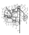
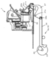
- FIG. 1 shows a medicine packaging device provided with a V ⁇ 1 and includes a moving collection container 2, a cleaner device 3, an opening / closing device 4 and a packaging device 5 (only the hopper 26 is disclosed) in addition to the V ⁇ 1.
- the V rod 1 has end plates 7 fixed to both ends of the side plate 6, and an open / close plate 8 is rotatably provided on both end plates 7.
- V ⁇ 1 is disposed above the movable collection container 2 moved to the origin position, extends from both ends of the first support wall 10 erected on the base 9, and is fixed to the end plate 7. Is supported by.
- the side plate 6 is made of an aluminum alloy. As shown in FIG. 5, a plurality of horizontal reference lines 1a are formed on the inner surface at predetermined intervals by anodizing. Each horizontal reference line 1a is visible from the outside when the surface of the medicine (powder) accommodated in the V ⁇ 1 is smoothed using the spatula 45 for packaging machines.
- a pair of upper and lower guide walls 12 are provided on the rear surface of the side plate 6 so as to protrude in the longitudinal direction.
- a ridge 12a is formed on the opposing surface of the guide wall 12.
- Arms 13 extend from both ends of the opening / closing plate 8 in the same direction at right angles.
- the arm portion 13 is rotatably connected to the end plate 7 around the support shaft 13a, and is opened and closed with respect to the side plate 6 by a first opening / closing device 4a described below.
- a partition plate 14 is disposed on the side plate 6 so as to freely reciprocate (in the left-right direction in FIG. 1).
- An arm portion 15 extends from the partition plate 14 toward the rear side of the side plate 6, and a pair of upper and lower rollers 16 are provided on the arm portion 15.
- a guide groove 16 a that engages with the protrusion 12 a of the guide wall 12 is formed at the center of the outer peripheral surface, and the roller 16 rolls on the guide wall 12.
- FIG. 6 there is shown a cross-sectional view in the depth direction of a V-shaped shape having various features on the opening / closing plate 8, and (1) is a conventional V-shaped 1 in which the opening / closing plate 8 is a flat plate.
- the horizontal distance from the opening / closing plate 8 to the side plate 6 is lower than the line connecting the upper and lower edges of the opening / closing plate 8 (line aa ′).
- (2) is an example of V ⁇ 1 in which a curved surface portion that is convex upward is provided on the open / close plate 8, and (3) is a bent portion on the open / close plate 8. As shown in FIG.
- FIG. 6 is a cross-sectional view taken along the line BB shown in FIG. 5. Note that the opening / closing plate 8 in the BB cross-sectional view shows only the upper surface of the opening / closing plate 8 facing the side plate 6.
- the opening / closing plate 8 is formed with a curved surface portion that is convex upward as the horizontal distance from the opening / closing plate 8 to the side plate 6 gradually or gradually approaches downward.
- the curved surface portion that is convex upward here is, for example, a portion that can be separated from the side plate 6 in the BB cross section as indicated by the curve aa ′ shown in the cross-sectional view of FIG. It protrudes above a straight line aa ′ formed by a point a ′ on the opening / closing plate 8 and a portion that can be separated from the side plate 6 from the point a on the nearby opening / closing plate 8, and the accommodation volume of the deep part of V ⁇ is increased.
- a curved surface formed on the opening / closing plate 8 that is formed by a curve aa ′ that decreases and widens the distance between the upper end of the opening / closing plate 8 and the side plate 6 in the same manner as the prior art V ⁇ 1 or larger than the prior art V ⁇ 1.
- the curved surface portion may be formed on the side plate 6 or on both the side plate 6 and the opening / closing plate 8. It should be noted that the curved surface portion formed on the side plate 6 refers to the side plate 6 on the side plate 6 facing the part that can be separated from the opening / closing plate 8 from a point on the side plate 6 near the part that can be separated from the opening / closing plate 8 in the BB cross section. It is a curved surface formed on the side plate 6 that is convex above the straight line formed by the point and has a curve that reduces the accommodation volume of the deep part of V ⁇ 1.
- the lower end of the curved surface portion is preferably located at the lower end of the opening / closing plate 8.
- At least one bent portion may be formed in the opening / closing plate 8 as described below.
- the bent portion referred to here is on the opening / closing plate 8 on the side of the portion that can be separated from the point b on the specific opening / closing plate 8 and the side plate 6 in the BB cross section.
- An inclination ⁇ (0 ° ⁇ ⁇ 90 °) of a straight line ab formed by an arbitrary point a with respect to a horizontal plane, a point b on the specific opening / closing plate 8 and the point b A portion of the opening / closing plate 8 that is bent so that the inclination ⁇ ′ of the straight line ba ′ formed by an arbitrary point a ′ on the opening / closing plate 8 facing the point a is ⁇ ′ ⁇ .
- any one of the lower and upper plates with respect to the bent portion of the opening / closing plate 8 may form a curved surface portion.
- the curved surface portion and the bent portion may be formed only on the upper surface of the opening / closing plate 8, that is, the surface facing the side plate 6.
- the partition plate 14 is preferably formed so as to correspond to a plurality of types of shapes of the opening / closing plate 8.
- the partition position by the partition plate 14, that is, the division number of the medicine (powder) accommodated in the V ⁇ 1 is determined by adjusting the movement position of the partition plate 14, and the permanent magnets 17a and 17b and the position detection sensors 18a and 18b.
- the permanent magnets 17a and 17b are arranged in a pair of upper and lower on the arm portion 15 of the partition plate 14.
- the position detection sensors 18a and 18b are respectively arranged in a pair of upper and lower at positions corresponding to the number of packages behind the V ⁇ 1 so as to detect the permanent magnets 17a and 17b.
- the moving collective container 2 has a configuration in which a plurality of divided containers 19 are detachably arranged in parallel.
- a roller 2 a provided on the back side rolls between the opposing walls 10 a and 10 a provided on the first support wall 10, and a projecting portion on the front side stands upright from the base 9.
- a rack 22 is provided on the back surface of the movable collection container 2, and a pinion 24 provided on the rotating shaft of a motor 23 fixed to the second support wall 20 is engaged.
- the motor 23 is driven, the movable collection container 2 reciprocates through the pinion 24 and the rack 22.
- Each of the divided containers 19 has a box shape with an upper opening, and is formed so that the upper edge of the side wall has an acute angle between the adjacent divided containers 19 so that the medicine (powder) can be divided reliably.
- the bottom plate 25 of each divided container 19 is attached so as to be rotatable about a support shaft 25a, and is urged to close the bottom by a spring 25b.
- the bottom plate 25 has a contact portion 25c extending laterally from the support shaft 25a.
- a magnet, a solenoid or the like may be used in addition to the spring 25b.
- the opening / closing device 4 includes a first opening / closing device 4 a for sequentially opening the bottom plate 25 of each divided container 19 on the hopper 26 and a second opening / closing device 4 b for opening the bottom plate 25 below the cleaner device 3.
- the first opening / closing device 4 a includes a first arm 27, a first cam 28, and a first arm 27 centered on a support shaft 29 a. It consists of a link 29 that is pivotally connected and transmits the operation of the first cam 28.
- the first cam 28 is rotated by a predetermined angle by the first motor 30.
- the rotational position of the first arm 27 is determined by the rotational position, and the pressing portion 27b of the first arm 27 presses the abutting portion 25c extending laterally from the support shaft 25a of the bottom plate 25. Thereby, the bottom plate 25 rotates and the lower part of the division container 19 opens.
- the second opening / closing device 4b includes a second arm 30 and a second cam 31 having the same configuration as the first opening / closing device 4a.
- the second arm 30 is provided with arm portions 30b and 30c at both ends of a shaft portion 30a that is rotatably disposed along the lower surface of the movable collecting container 2.
- One arm portion 30 c is in contact with the outer periphery of the second cam 31 whose tip is changed by driving the second motor 32.
- the cleaner device 3 includes a duct 34, a hand cleaner 35, and a suction device 36.
- the duct 34 has a suction port 34a at the center of the lower surface, and is disposed on the side of the end plate 7 so as to cover the back side of the opening of the dividing container 19 positioned below the suction port 34a.
- the suction device 36 includes a filter 36a and a fan 36b, to which the duct 34 and the hand cleaner 35 are connected.
- the packaging device 5 receives the medicine (powder) supplied from the powder supply device by the hopper 26, sequentially feeds the wrapped wrapping paper, and wraps it one by one (other than the hopper 26 is omitted).
- the partition plate 14 in the V ⁇ 1 is moved to a position corresponding to the desired number of packages, and if the partition plate 14 is positioned, the medicine (powder) is accommodated in the V ⁇ 1 as shown in FIG.
- the surface is leveled with a chemical leveling device (described later).
- the opening / closing plate The height of V ⁇ 1 having a curved portion and a bent portion at 8 is A + ⁇ and A + ⁇ ′ ( ⁇ > 0, ⁇ ′> 0), respectively, and is accommodated compared to the height A of V ⁇ 1 having the conventional opening / closing plate 8.
- the height of the surface of the applied drug is increased. Therefore, the operator who leveles the surface of the medicine can work at a position closer to that of the hand from his / her hand, so that it becomes easy to level.
- the width of the opening at an arbitrary height from the upper surface of the medicine (powder) is larger than the conventional one.
- the width of the opening at an arbitrary height from the upper surface of the medicine (powder) is larger than before, so the movable range of the medicine leveling device (scalar) is larger, so the leveling work is more than conventional. It becomes easy.
- the gap between the upper end of the opening / closing plate 8 and the side plate 6 is approximately the same as the V ⁇ 1 of the prior art or wider than the V ⁇ 1 of the prior art, the injection of the drug (powder) into the V ⁇ 1 is V It is the same as ⁇ 1 or easier than V ⁇ ⁇ 1 of the prior art.
- the movable collection container 2 is moved to the origin position, and the opening / closing plate 8 is opened, whereby the medicine (powder) is separated into each divided container 19.
- the medicine (powder) in V ⁇ 1 is evenly distributed as described above, it can be equally divided into the divided containers 19.
- the deep part of V ⁇ 1 has a small width (length in the front-rear direction)
- the drug injected into the deep part becomes deep. Therefore, even if the surface where the drug is smoothed as described above, The distance from the lowermost part to the dividing container is the same as that of the prior art V ⁇ ⁇ 1. Therefore, the blowing-up of the medicine when the medicine falls from the V ⁇ ⁇ 1 to the dividing container 19 can be suppressed to the same level as before.
- each divided container 19 is sequentially positioned above the hopper 26, and is packaged by opening the bottom plate 25 by the first opening / closing device 4a. Get medicine.
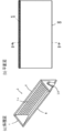
- FIGS. 7 to 9 are plan views of the medicine leveling device 100, FIG. 7 is an overall view thereof, and FIG. 8 is a schematic view for performing the process of leveling the medicine surface provided on the left side of FIG.
- FIG. 9 shows an enlarged view of a portion for assisting the step of leveling the drug surface provided on the right side of FIG.
- the medicine leveling device 100 is a thin and substantially flat member in the thickness direction, the illustration in the thickness direction is omitted.
- the medicine leveling device 100 includes a gripping member 102 that extends in the length direction, a rod-like member 104 that is integrally coupled to both ends thereof, and an auxiliary leveling member 105, and is injection-molded with a hard resin material.
- the gripping member 102 includes a long handheld first gripping member 102b and a second gripping member 102a formed integrally with the tip thereof.
- the second gripping member 102a is connected to the rod-shaped member 104 and is provided to secure a distance in the length direction of the rod-shaped member 104, and is a plate-shaped region 102d that is wider than the first gripping member 102b in the width direction. have. Further, as shown in FIG.
- the second gripping member 102 b has an edge portion 102 c that abuts on the opening / closing plate 8 extending in the distal direction from the plate-like region 102 when the medicine surface is smoothed.
- the second gripping member 102 a is rectangular, but may be other than a rectangle as long as the first gripping member 102 b is enlarged in the width direction.
- the recessed part of the reference number 103 is an injection molding trace.
- a connecting member 106 extending from the plate-like region 102d toward the rod-like member 104 is provided on the opposite side of the edge portion 102c of the second gripping member 102a in the width direction.
- the medicine leveling member 100 performs the leveling work while guiding the edge portion 102c to the opening / closing plate 8 and positioning the edge portion 102c in the traveling direction (the paper surface direction in FIG. 11).
- the edge portion 102c is inclined at ⁇ E with respect to the rod-shaped member 104 and the drug surface. From the viewpoint of equalizing the medicine with a margin in V ⁇ ⁇ 1, ⁇ E can be brought close to 90 ° to raise the medicine leveling device 100 in the direction of arrow A in FIG.
- there is a limit until the edge portion 102c contacts the opening / closing plate 8 (inclination limit in the direction of arrow B).
- the opening / closing plate 8 as shown in FIGS.
- the width w of the rod-shaped member 104 is preferably as small as possible, and may be any shape that can easily “cut” the convex surface of the medicine. Examples thereof include cross-sectional shapes such as a wing shape, a cylindrical shape, and an elliptical shape. Further, a steel wire or the like may be used as long as it easily cuts the convex surface of the medicine.
- the width w of the rod-shaped member 104 is preferably as small as possible. Therefore, when injection molding or the like is performed on the entire medicine leveling device 100 in terms of manufacturing, the thickness of the second gripping member 102a is also the thickness of the rod-shaped member 104 in manufacturing. It is often the same level. For this reason, the strength of the connection between the second gripping member 102a and the rod-shaped member 104 tends to be weak. Accordingly, in the medicine leveling device 100 of FIGS. 7 to 9, the connecting member 106 and the plate-like region 102d also serve as a reinforcing member.
- an auxiliary leveling member 105 of the medicine leveling device 100 of FIG. 7 is provided at the end opposite to the bar-shaped member 104.
- the medicine leveling operation is performed by the rod-shaped member 104, but it is this subsidy to secure the role of scavenging the medicine and other things stuck to the opening and closing plate 8 etc., which cannot be completely leveled by this. It is the leveling member 105.
- the auxiliary leveling member 105 is a flat plate member that is expanded and connected in the width direction at the tip of the first gripping member 102b.
- the auxiliary leveling member 105 is integrally formed of a plate-like region portion 105b and an edge portion 105a in order from the first gripping member 102b toward the tip. It is preferable that the portion for performing the scraping operation described above becomes the edge portion 105a and is provided on both sides in the width direction.
- FIG. 12 is a partial cross-sectional view of the touch pen member 107 along the longitudinal direction.
- the touch pen type member 107 is made of an electrically conductive material, and the outside of a pen core shaft portion 107b made of a conductive material that is electrically conductive with a soft pen core tip portion 107a such as rubber is covered with a pen body portion 107c made of an insulating material. It has a structure that is called.
- the air gap between the pen body portion 107c and the pen core shaft portion 107b does not have an air layer with a low relative dielectric constant. It is desirable to do.
- the medicine leveling device 100 can be used for both the leveling of the drug (powder) in the V ⁇ 1 and the operation of the drug packaging device.
- the operator often used the medicine leveling device 100 as a touch pen to the monitor while using powdered medicine, and in this case, the medicine adhered to the monitor was severely contaminated on the screen, and the operation mistakes associated therewith were possible. The problem was that there was a characteristic.
- the touch pen type member 107 as shown in FIG. 12 is used, the operator can clearly recognize one end for medicine leveling and the other end for touching the monitor. Screen contamination can be prevented.
- FIG. 10 shows a modified example 200 of the medicine leveling device 100 shown in FIGS. 7 to 9 (hereinafter simply referred to as “the drug leveling device 100”).
- FIG. 10 shows an enlarged view similar to FIG.
- the flat plate region 102d of the second gripping member 102a in the medicine leveling device 100 is not provided, and the rod-like member 104 and the connecting portion 106 are directly connected from the tip of the first gripping member 102b.
- the reinforcing member 108 is provided because the strength corresponding to the flat plate region 102d cannot be reinforced.
- the reinforcing member 108 is a belt-like plate member (or a rod-like member) that connects the connecting portion between the rod-like member 104 and the connecting member 106 and the tip of the first gripping member 102b.
- reinforcing member other reinforcing members may be considered as long as the connecting state between the gripping member and the rod-shaped member 104 and the strength of the rod-shaped member 104 itself are ensured. It should also be mentioned that the connecting member 106 and the plate-like region 102d of the medicine leveling device 100 also have a role as a reinforcing member.
- V ⁇ 6 Side plate 8: Opening / closing plate 14: Partition plate 100: Drug leveling instrument 102: Gripping member 104: Bar-shaped member
Landscapes
- Engineering & Computer Science (AREA)
- Mechanical Engineering (AREA)
- Quality & Reliability (AREA)
- Basic Packing Technique (AREA)
- Medical Preparation Storing Or Oral Administration Devices (AREA)
- Supply Of Fluid Materials To The Packaging Location (AREA)
Abstract
【課題】本発明は、散薬を均等に分割するための構造に特徴を備えた薬剤包装装置、およびこれに用いる薬剤収容容器(V枡)、並びにV枡内の薬剤を均す薬剤均し器具を提供する。 【解決手段】本薬剤収容容器(V枡)の前記開閉板は、その閉鎖時に、前記開閉板と前記側板までの水平距離が前記開閉板の上縁と下縁とを結ぶ線上よりも下方に向かって連続的又は階段的に漸近する形状を有する。また、本薬剤均し器具は、手持ち用の把持部分と、該把持部分の遠位先端に把持部分の主軸線に対して鋭角に傾斜して把持部分に一体に装着された薬剤を掻き均すための一直線の棒状部材とを備える。
Description
本発明は処方された散薬等の薬剤を均等に分割した後、1包毎に包装する薬剤包装装置、特に、散薬を均等に分割するための構造に特徴を備えた薬剤包装装置、およびこれに用いる薬剤収容容器(V枡)、並びにV枡内の薬剤を均す薬剤均し器具に関するものである。
従来、薬剤包装装置では、薬剤を1包ずつ包装するために、V枡内に処方情報に従った量の薬剤を収容し、その表面を分包機用ヘラ等の均し器具を用いて均等に均した後、V枡からその下方に位置する複数の分割容器に落下させるようにしている。
なお、V枡からその下方に位置する複数の分割容器に落下させる際のV枡については従来から知られている。(例えば特許文献1参照)。
また、前記均し器具は、V枡内に収容された薬剤に対して、V枡の長手方向に一方側から他方側、或いは、他方側から一方側の方向に移動させて薬剤を掻きならす均し動作を複数回繰り返すことにより、薬剤の表面が平坦となるようにすることを可能にするものである。
しかしながら、少量の薬剤を均等に分割するために、V枡に収容した薬剤の表面を同一水平面内に位置するように均等にならすのは著しく困難であり、不正確とならざるを得ない。
例えば、小児に対して投与される薬剤を分割する場合である。
薬剤が少量である場合、前記薬剤包装装置においてはV枡内に収容された薬剤の体積及び上面の表面積は標準的な量に比べ小さくなる。
このとき均し器具にあっては正確にならすことができる薬剤収容量に制限があることに加え、薬剤がV枡の薬剤収容部の深部に収容されることから、ヘラの可動範囲が制限され、収容した薬剤の表面を水平面にすることが困難である。
特に、少量の薬剤をV枡の薬剤収容部に収容し、かつ、一度に分割する数を多くする必要が生じた場合は、上記の可動範囲の問題に加え、均す範囲が増大するために収容した薬剤の表面を水平面にすることはさらに困難である。したがって、均し動作の速さや切り出し量などをV枡内に収容された薬剤の収容量に応じて調整することができないという問題があった。
また、ここで上記均し器具について説明すると、従来の均し器具は、V枡の薬剤収容部に収容・貯留された薬剤を均一にするためにヘラを傾斜させながら往復方向に動かして薬剤表面の凹凸のうち凸面を掃き崩して凹面を埋めていくことで表面を均一に均していくものであった。しかしながら、従来の均し器具では、ヘラで凸面を掃き崩す量しか凹面を埋めることができず均し作業に時間を要していた。また、逆に凸面を一回で多く掃き崩すとすれば、いきおい最終的な均し面より深く凸面を掃き崩してしまい凹面を埋める量以上の余分な薬剤がヘラの前端に溜まっていくという問題があった。
そこで、第一の本発明では、V枡内に収容した少量の薬剤を分割する場合においても薬剤を容易に均して正確な分割することを可能とする薬剤包装装置及びこれに用いるV枡を提供することを課題とする。
また、第二の本発明では、V枡に貯留する薬剤の表面を少ない工程で確実に均すための均し器具を提供することを課題とする。
第一の本発明は、前記課題を解決するための手段として、上方から投入された薬剤を貯留又は落下させ、薬剤をそれぞれ一包ずつ包装する薬剤包装装置に用いる薬剤収容容器(以下、「V枡」とも称する)を提供している。このV枡は、側板の両端部に端板をそれぞれ固定し、前記側板に対して下縁が接離可能となるように開閉板を設け、該開閉板と側板との間で前記端板に向かって移動させることにより貯留する薬剤の分割数を調整可能な仕切り板とを設け、前記開閉板は、その閉鎖時に、前記開閉板と前記側板までの水平距離が下方に向うにつれ前記開閉板の上縁と下縁とを結ぶ線上と前記側板までの水平距離よりも連続的又は階段的に漸近する形状を有する。
また、本発明は、上方から投入された薬剤を貯留又は落下させ、薬剤をそれぞれ一包ずつ包装する薬剤包装装置をも提供している。本薬剤包装装置では、上記同様のV枡と、V枡の下方に並設され、開閉可能な底板を有し、V枡から落下する薬剤を均等に分割して受け止める複数の分割容器と、前記複数の分割容器から落下する薬剤をそれぞれ1包ずつ包装する包装装置と、を備え、前記開閉板は、その閉鎖時に、前記開閉板と前記側板までの水平距離が下方に向うにつれ前記開閉板の上縁と下縁とを結ぶ線上と前記側板までの水平距離よりも連続的又は階段的に漸近する形状を有する。
本発明の薬剤収容容器(V枡)および薬剤包装装置によれば、V枡がその断面形状において下方に向かうにつれて従来のV枡の開閉板よりも狭くなっていくように形成されている。したがって、少量の薬剤を貯留させた場合であっても、深さ方向を大きくすることができ上方視の面積が広くなったところまで散剤の上面を位置させることができる。その結果、作業者は包装機用ヘラでV枡の薬剤の表面を長手方向(図1の左右方向)にならす均し動作を確実に複数回繰り返すことができ、薬剤を均等に分割することができる。
例えば具体的には、開閉板は、上に向かって凸状となる曲面部を設けることで開閉板と側板との間の水平距離を下方に向かって従来のV枡よりも連続的に近づけたり、少なくとも一つ屈曲部を設けたりすることで開閉板と側板との間の水平距離を下方に向かって階段的に近づけていく構成をしている。なお、また、開閉板は、着脱可能に形成した。
また、第二の本発明は薬剤をそれぞれ一包ずつ包装する薬剤包装装置に用いる薬剤収容容器に収容された薬剤を均す均し作業に用いられる薬剤均し器具を提供する。本薬剤均し器具は、手持ち用の把持部分と、把持部分の遠位先端に把持部分の主軸線に対して鋭角に傾斜して把持部分に一体に装着された薬剤を掻き均すための一直線の棒状部材と、を備えている。
本薬剤均し器具は、V枡(仕切り板は必須でない)に貯留された薬剤(散剤)の表面を均すためのものである。上述するように、従来の均し器具は、薬剤表面の凹凸のうち凸面を掃き崩して凹面を埋めていくことで表面を均していくものであり、作業工数が多く時間を要していたが、本発明の薬剤均し器具では薬剤の均し作業において新たな知見を得てこの知見に基づいた構成のものを創作提供するに至った。具体的には、粉状体としての薬剤(散剤)は、薬効成分は異なってもその薬剤の大部分は賦形剤等であるからその粒径、重量、凝集度、粘性等が所定の特殊性を有しており、これに注目して検証したところ、薬剤の表面を均すには従来のようなかき揚げ、押し付けという工程よりも、むしろ単に薬剤の凸面を切っていくだけの工程にする方が望ましいという知見を得た。その結果、薬剤表面の凸面を切っていく作業を最も簡単に行うには薬剤表面に接する部材の形状として棒状部材することが好ましかった。したがって、本発明では、これを形状として具現化している。
また、前記棒状部材は、把持部分の側部のエッジ部に対する傾斜角θEは、
28°=80°‐θ0°≦θE°≦100°-θ0°=53°
θ0:上記V枡の開閉板の上端と下端とを結ぶ線と前記側板との挟角
であることが好ましい。
均し作業中の薬剤均し器具は、その先端の棒状部材が薬剤表面に十分に接する必要がある。その観点では、薬剤均し器具を起こして使用した場合であっても棒状部材が薬剤表面に十分に接するようにする必要があり、θEが大きく90°に近づくことも差し支えない。その一方、薬剤均し器具により安定的な均し作業を実行させるという観点からみると、その側部のエッジ部をV枡の開閉板に当接させることで傾斜方向を位置決めしつつ移動させることが好ましい。このとき開閉板に当接するエッジ部の傾斜角θE(=90°-θ0°)は、従来のV枡の開閉板の場合の傾斜角と同じ又はこれより小さい角度(=薬剤均し器具が寝かされる角度)であることが好ましい。
この相反する両観点を鑑みると、両観点とも満足するθE=90°-θ0°近傍であることが望ましい。
また、種々のV枡に対応する汎用の薬剤均し器具を創作することを考慮して検証したところθ0は一般に52°前後であり、これに±10°程度の範囲であれば均し作業の安定性への影響が少ないこともわかった。以上を総合すると、
28°=80°‐θ0°≦θE°≦100°-θ0°=53°
であることが好ましいことが知得された。
28°=80°‐θ0°≦θE°≦100°-θ0°=53°
θ0:上記V枡の開閉板の上端と下端とを結ぶ線と前記側板との挟角
であることが好ましい。
均し作業中の薬剤均し器具は、その先端の棒状部材が薬剤表面に十分に接する必要がある。その観点では、薬剤均し器具を起こして使用した場合であっても棒状部材が薬剤表面に十分に接するようにする必要があり、θEが大きく90°に近づくことも差し支えない。その一方、薬剤均し器具により安定的な均し作業を実行させるという観点からみると、その側部のエッジ部をV枡の開閉板に当接させることで傾斜方向を位置決めしつつ移動させることが好ましい。このとき開閉板に当接するエッジ部の傾斜角θE(=90°-θ0°)は、従来のV枡の開閉板の場合の傾斜角と同じ又はこれより小さい角度(=薬剤均し器具が寝かされる角度)であることが好ましい。
この相反する両観点を鑑みると、両観点とも満足するθE=90°-θ0°近傍であることが望ましい。
また、種々のV枡に対応する汎用の薬剤均し器具を創作することを考慮して検証したところθ0は一般に52°前後であり、これに±10°程度の範囲であれば均し作業の安定性への影響が少ないこともわかった。以上を総合すると、
28°=80°‐θ0°≦θE°≦100°-θ0°=53°
であることが好ましいことが知得された。
さらに、前記把持部分と前記棒状部材との間には補強部材が備えられる。
薬剤の凸表面を切っていく棒状部材は、「切る」という目的を達するためには勢い細く脆弱な部材となっていく。このため補強部材を設けることが好ましい。
第一の本発明の薬剤包装装置及びこれに用いるV枡では、V枡内に収容した少量の薬剤を分割する場合においても薬剤を容易に均して正確な分割することを可能とする点で有利である。
また、第二の本発明の薬剤均し器具では、V枡に貯留する薬剤の表面の均し作業時間を短縮化しつつも、確実な均し工程を実行することができる。
以下、本発明の実施形態を添付図面に従って説明する。
図1は、V枡1を備えた薬剤包装装置を示し、V枡1のほかに、移動集合容器2、クリーナー装置3、開閉装置4及び包装装置5(ホッパー26のみ開示)を備えている。
V枡1は、図2に示すように、側板6の両端に端板7を固定し、両端板7に開閉板8を回動自在に設けたものである。
また、V枡1は、原点位置に移動させた移動集合容器2の上方に配設され、ベース9に立設させた第1支持壁10の両端から延び、端板7に固定されたアーム11によって支持されている。
前記側板6はアルミ合金で形成され、図5に示すように、その内面にはアルマイト処理により所定間隔で複数の水平基準ライン1aが形成されている。各水平基準ライン1aは、V枡1内に収容する薬剤(散薬)の表面を、包装機用ヘラ45等を利用してならすときに外方から目視可能となっている。
前記側板6の背面には上下一対のガイド壁12が長手方向に突設されている。ガイド壁12の対向面には突条12aがそれぞれ形成されている。前記開閉板8の両端部から直角同方向に腕部13がそれぞれ延設されている。この腕部13は、支軸13aを中心として端板7に回動自在に連結され、下記する第1開閉装置4aによって側板6に対して開閉するようになっている。
前記側板6には、仕切板14が往復移動自在(図1の左右方向)に配設されている。仕切板14から側板6の後方に向かってアーム部15が延設され、そのアーム部15には上下一対のローラ16が設けられている。ローラ16は、その外周面中央に、前記ガイド壁12の突条12aに係合するガイド溝16aが形成され、ガイド壁12を転動する。
ここで開閉板8の詳細について図6を使って説明する。図6を参照すれば、開閉板8に各特徴をもった形状のV枡の深さ方向の断面図を示しており、それぞれ(1)は、開閉板8が平板である従来型V枡1の例を示しており、(2)(3)は、開閉板8から側板6までの水平距離が開閉板8の上縁と下縁とを結ぶ線上(a-a’線)よりも下方に向かって連続的又は階段的に漸近するものとして、(2)は、開閉板8に上方に凸状となる曲面部を設けたV枡1の例、(3)は、開閉板8に屈曲部を設けたV枡1の例を示しており、(4)(5)(6)はそれぞれ(1)(2)(3)のV枡1に同量の薬剤を収容した際に、各薬剤の表面の高さが変化する様子を示し、図5平面図に示すBB断面図を示している。なお、BB断面図中の開閉板8は、側板6と対向する開閉板8の上面のみを示す。
開閉板8から側板6までの水平距離が下方に向かって連続的又は階段的に漸近するものとして下記のように前記開閉板8は上に向かって凸状となる曲面部が形成されている。
ここで言う上に向かって凸状となる曲面部とは、一例として図6(2)の断面図に表記の曲線aa'のように、BB断面おいて、側板6と切離可能となる部位近傍の開閉板8上の点aから側板6と切離可能となる部位と相対する開閉板8上の点a'とが成す直線aa'より上に凸となり、V枡の深部の収容体積を減少させ、且つ、開閉板8上端と側板6との間隔を従来技術のV枡1と同様又は従来技術のV枡1よりも広げる曲線aa'からなる、開閉板8に形成された曲面をいう。なお、前記曲面部は、側板6に形成しても、側板6と開閉板8の両方に形成してもよい。なお、側板6に形成する曲面部とは、BB断面において、開閉板8と切離可能となる部位近傍の側板6上の点から開閉板8と切離可能となる部位と相対する側板6上の点とが成す直線より上に凸となり、V枡1の深部の収容体積を減少させる曲線からなる、側板6に形成された曲面をいう。
なお、前記曲面部の下端は開閉板8の下端に位置させた方が好ましい。
また、開閉板8から側板6までの水平距離が下方に向かって連続的又は階段的に漸近するものの他の例として下記のように開閉板8に少なくとも一つ屈曲部を形成してもよい。
ここで言う屈曲部とは、一例として図6(3)に示すように、BB断面においてある特定の開閉板8上の点bと側板6と切離可能となる部位側の開閉板8上の任意の点aとが成す直線abの、水平面を基準とした傾きθ(0°<θ<90°)と、前記ある特定の開閉板8上の点bと前記の点bに対して前記の点aと相対する開閉板8上の任意の点a'とが成す直線ba'の前記基準における傾きθ’とが、θ’<θとなるように屈曲させた開閉板8の部位をいう。なお、開閉板8上の任意の点a'とは、仮にθ’=θに形成した場合、側板6と切離可能となる部位近傍の開閉板8上の点aと前記ある特定の開閉板8上の点bとが成す半直線ab上に位置するab<aa'となる点をいう。
またその他の例として、図示しないが開閉板8の前記屈曲部に対して下方・上方の板のどちらか一方が曲面部を形成してもよい。
なお、前記曲面部及び屈曲部は開閉板8の上面、つまり、側板6に対して対向する面のみに形成してもよい。
なお、仕切板14は開閉板8の複数種類の形状に対応するように形成することが好ましい。
また、開閉板8は着脱可能に形成してもよい。なお、V枡1の構成を変えるために、開閉板8を含む他の部材を含んだ構成で着脱可能に形成してもよい。
前記仕切板14による仕切位置すなわちV枡1内に収容する薬剤(散薬)の分割数は、仕切板14の移動位置を調整することにより決定し、永久磁石17a,17b及び位置検出センサ18a,18bにより検出する。永久磁石17a,17bは、仕切板14のアーム部15に上下一対で配設されている。一方、位置検出センサ18a,18bは、前記各永久磁石17a,17bを検出するように、前記V枡1の背後の各分包数に応じた位置に上下一対でそれぞれ配設されている。
移動集合容器2は、複数個の分割容器19を着脱可能に並設一体化した構成である。この移動集合容器2は、背面側に設けたローラ2aが前記第1支持壁10に設けた対向壁10a,10a間を転動し、前面側の突出部分がベース9から立設した第2支持壁20に設けた上下一対のローラ21,21間にガイドされることにより、図1中左右方向に移動自在となっている。また、移動集合容器2の背面にはラック22が設けられ、前記第2支持壁20に固定したモータ23の回転軸に設けたピニオン24が噛合している。これにより、モータ23を駆動すると、移動集合容器2は、ピニオン24及びラック22を介して往
復移動する。
復移動する。
前記各分割容器19は全て上方が開口する箱形状で、隣接する分割容器19同士で側壁上縁が鋭角となるように形成され、薬剤(散薬)を確実に分割できるようになっている。各分割容器19の底板25は、図2に示すように、支軸25aを中心として回動自在に取り付けられ、スプリング25bによって底を閉塞するように付勢されている。底板25には、支軸25aから側方に当接部25cが延設されている。なお、分割容器19の下端開口部を底板25で閉塞する手段としては、前記スプリング25bのほかに、マグネットやソレノイド等を使用してもよい。
開閉装置4は、各分割容器19の底板25を、順次、ホッパー26上で開放させる第1開閉装置4aと、クリーナー装置3の下方で開放させる第2開閉装置4bとから構成されている。
前記第1開閉装置4aは、図3に示すように、支軸27aを中心として回動自在に設けた第1アーム27と、第1カム28と、第1アーム27に支軸29aを中心に回動自在に連結され、第1カム28の動作を伝達するリンク29とからなる。第1カム28は第1モータ30によって所定角度回転する。そして、回転位置によって第1アーム27の回動位置が決まり、第1アーム27の押圧部27bが前記底板25の支軸25aから側方に延設された当接部25cを押圧する。これにより、底板25が回動して分割容器19の下方が開口する。
前記第2開閉装置4bは、図2及び図4に示すように、前記第1開閉装置4aと同様な構成の第2アーム30と第2カム31とからなる。第2アーム30は、移動集合容器2の下面に沿って回転自在に配設された軸部30aの両端に腕部30b,30cをそれぞれ設けたものである。一方の腕部30cは、先端が第2モータ32の駆動により回転位置を変更する第2カム31の外周に当接している。
クリーナー装置3は、図1に示すように、ダクト34、ハンドクリーナー35及び吸引装置36で構成される。ダクト34は、下面中央部に吸引口34aを有し、その下方に位置する分割容器19の開口部の背面側を覆うように、前記端板7の側方に配設されている。吸引装置36は、フィルタ36a及びファン36bを備え、前記ダクト34及びハンドクリーナー35がそれぞれ接続されている。
前記包装装置5は、散薬供給装置から供給した薬剤(散薬)をホッパー26で受け止め、巻回した包装紙を順次供給して1包ずつ包装するものである(ホッパー26以外は図略)。
次に、前記構成の薬剤分割包装装置の動作を説明する。
まず、V枡1内の仕切板14を所望分包数に対応する位置に移動させ、仕切板14が位置決めされれば、図7に示すようにV枡1内に薬剤(散薬)を収容し、その表面を薬剤均し器具(後述)でならす。
上述した図6(1)(2)(3)に示すような開閉板8に各特徴をもった形状のV枡1に同量の薬剤を収容した際の高さを比較した場合、開閉板8に曲面部および屈曲部を持つV枡1の高さはそれぞれA+α、A+α'(α>0、α’>0)となり、従来の開閉板8をもつV枡1の高さAに比べ収容された薬剤の表面の高さは高くなる。したがって、薬剤表面をならす作業者は、自身の手から従来より近い位置で作業できるために均しやすくなる。
また、図6(4)(5)(6)は開閉板8に各特徴をもったV枡1に同量の薬剤を収容した際に、各薬剤の表面の高さを揃えて図示したものである。
本願発明は、従来より薬剤(散薬)上面からの任意の高さにおける開口部の幅が従来よりも大きくなっていることが明白にわかる。
したがって、上記の理由から、薬剤(散薬)上面からの任意の高さにおける開口部の幅が従来よりも大きいために薬剤均し器具(ヘラ)の可動範囲が大きいため均し作業が従来よりも容易になる。また、開閉板8上端と側板6との間隔が従来技術のV枡1と同程度又は従来技術のV枡1よりも広いので、V枡1への薬剤(散薬)の投入が従来技術のV枡1と同程度、又は、従来技術のV枡1よりも行い易い。
このようにしてV枡1内への薬剤(散薬)の収容が完了すれば、移動集合容器2を原点位置に移動させ、開閉板8を開放することにより、薬剤(散薬)を各分割容器19に分割する。V枡1内の薬剤(散薬)は、前述のように均等にならされているため、各分割容器19に均等に分割することができる。また、V枡1の深部は幅が(前後方向の長さが)小さいため、深部に投入された薬剤が深くなるので、上記のように薬剤をならす表面を高くしても、V枡1の一番下の部分から分割容器までの距離が従来技術のV枡1と同じである。
従って、V枡1から分割容器19に薬剤が落下した時の薬剤の吹き上りを従来と同等に抑えることができる。
従って、V枡1から分割容器19に薬剤が落下した時の薬剤の吹き上りを従来と同等に抑えることができる。
次いで、各移動集合容器2を移動させながら、順次各分割容器19をホッパー26の上方に位置決めし、第1開閉装置4aによって底板25を開放することにより包装し、正確に分包された分包薬を得る。
ここで薬剤均し器具について言及する。
図7~図9は、薬剤均し器具100の平面図が示されており、図7はその全体図、図8は図7の左側に設けられた薬剤表面を均す工程の概ねを行うための部分の拡大図、図9は図7の右側に設けられた薬剤表面を均す工程を補助するための部分の拡大図を示している。
なお、薬剤均し器具100は厚み方向に薄く略平板状の部材であるため厚み方向の図は省略する。
図7~図9は、薬剤均し器具100の平面図が示されており、図7はその全体図、図8は図7の左側に設けられた薬剤表面を均す工程の概ねを行うための部分の拡大図、図9は図7の右側に設けられた薬剤表面を均す工程を補助するための部分の拡大図を示している。
なお、薬剤均し器具100は厚み方向に薄く略平板状の部材であるため厚み方向の図は省略する。
薬剤均し器具100は、概ね長さ方向に延びる把持部材102と、その両端に一体結合された棒状部材104と、補助均し部材105とを有し、硬い樹脂材料で射出成形されている。把持部材102は、手持ち用の長い第一把持部材102bとその先端と一体形成される第二把持部材102aとで構成される。第二把持部材102aは、棒状部材104に連結し、棒状部材104の長さ方向の距離を確保するために設けられるものであり、幅方向に第一把持部材102bよりも拡がった板状領域102dを有している。また、第二把持部材102bは、図11に示すように薬剤表面を均す作業を行うときに開閉板8に当接するエッジ部102cが板状領域102から先端方向に延びている。図7の例では第二把持部材102aは矩形であるが、第一把持部材102bを幅方向に拡大するものであれば矩形以外であってもよい。なお、参照番号103の凹部は射出成形跡である。
また、第二把持部材102aのエッジ部102cと幅方向反対側には、板状領域102dから棒状部材104に向けて延びる連結部材106が設けられている。
薬剤均し部材100は、そのエッジ部102cを開閉板8に接触、位置決めさせて進行方向(図11紙面方向)にガイドしながら均し作業を行うことが好ましい。図11では、このエッジ部102cは、棒状部材104及び薬剤表面に対してθEに傾斜している。θEはV升枡1内でスペースに余裕をもたせて薬剤を均すという視点からは薬剤均し器具100を図11の矢印A方向に起こすべく90°に近づけるのは差し支えない。その一方、エッジ部102cが開閉板8に当接するまでが限度であり(矢印B方向の傾斜限度)、その意味ではθEは、従来の開閉板8の傾斜角であるθ1と同じ又は小さい方が好ましい。したがって、θEは、相反する90°≧θE°、θE°≦θ1=90°-θ0°となる。
したがって、上記条件ともに両観点とも満足するθE=90°-θ0°近傍が一般的には望ましいと考えられる。
ここで実際のθ0は、通常(従来)の平板状の開閉板8ではθ0=52°近傍であることが一般的である。また、薬剤均し部材100の汎用性を考慮すれば図6(2)(3)に示すような開閉板8にも対応可能であるべきである。したがって、図6(1)(2)(3)で種々のθEの薬剤均し器具100を検証した。その結果、±10°(より好ましくは±5°)程度の範囲であれば均し作業の安定性を確保できることがわかった。したがって、θEは、
28°=80°‐θ0°≦θE°≦100°-θ0°=53°
であることが好ましいことが知得された。
したがって、上記条件ともに両観点とも満足するθE=90°-θ0°近傍が一般的には望ましいと考えられる。
ここで実際のθ0は、通常(従来)の平板状の開閉板8ではθ0=52°近傍であることが一般的である。また、薬剤均し部材100の汎用性を考慮すれば図6(2)(3)に示すような開閉板8にも対応可能であるべきである。したがって、図6(1)(2)(3)で種々のθEの薬剤均し器具100を検証した。その結果、±10°(より好ましくは±5°)程度の範囲であれば均し作業の安定性を確保できることがわかった。したがって、θEは、
28°=80°‐θ0°≦θE°≦100°-θ0°=53°
であることが好ましいことが知得された。
また、棒状部材104の幅wは小さいほど好ましく、薬剤の凸面を「切り」やすい形状であればよく、例えば翼形状、円筒状、楕円状等の断面形状が挙げられる。また、薬剤の凸面を「切り」やすいものであれば、鋼線などであってもよい。
なお、上述するように棒状部材104の幅wは小さいほど好ましいため、製造上、薬剤均し器具100全体として射出成形等を行うと製造上、第二把持部材102aの厚みも棒状部材104の厚みと同程度になる場合が多い。このため第二把持部材102aやこれと棒状部材104との連結の強度が弱くなりやすい。したがって、図7~図9の薬剤均し器具100では、連結部材106や板状領域102dが補強部材としての役割をも有している。
次に、図9を参照すれば棒状部材104と反対側の端部に図7の薬剤均し器具100の補助均し部材105が設けられている。概ね、棒状部材104で薬剤の均し作業は実行されるが、これで完全に均せなかった隅の位置や開閉板8等にこびりついた薬剤その他のものを掻き出す役割を担保するのがこの補助均し部材105である。
補助均し部材105は、第一把持部材102bの先端で幅方向に拡大して連結されている平板状の部材である。補助均し部材105は、第一把持部材102bから先端に向かって順に板状領域部105bとエッジ部105aとで一体に構成されている。上述する掻き出し作業を行う部分が、エッジ部105aとなり、幅方向両側に設けられることが好ましい。
なお、補助均し部材105の代替えとして、図12に示すように薬剤分包装置に備え付けのタッチパネル式モニタを操作するタッチペン式部材107が設けられてもよい。図12は、タッチペン式部材107の長手方向に沿った部分断面図を示している。タッチペン式部材107は、概ね導電性材料でゴム等の柔らかいペン芯先端部107aと電気的に導通する導電性材料製のペン芯軸部107bの外側が絶縁性材料製のペン本体部107cで覆われる構造を持つ。タッチペン式部材107の使用者の持ち手との静電容量結合を保つためには、ペン本体部107cとペン芯軸部107bとの間は、比誘電率の低い空気層の空隙がない構造にすることが望ましい。
このタッチペン式部材107を設けた場合、薬剤均し器具100によりV枡1内の薬剤(散薬)を均す作業と、薬剤分包装置の操作と、を兼用して行うことができる。実際に従来、作業者が散薬を使用しながら薬剤均し器具100をモニタへのタッチペンとして使用する場合が多く、この場合にモニタへの薬剤付着がひどく画面の汚れ、これに伴う操作ミスの可能性がある点が問題であった。これに対して、図12のようなタッチペン式部材107にすると一端を薬剤均し用、他端をモニタへのタッチ用と明確に作業者に認識させることができ、薬剤均し器具100によるモニタ画面の汚れを防止することができる。
次に、図7~図9に示す薬剤均し器具100(以下、単に「上記薬剤均し器具100」と称する)の変形例200を図10に示している。図10は、図8と同様の拡大図を示している。図10の薬剤均し器具200では、薬剤均し器具100における第二把持部材102aの平板領域102dを設けず、第一把持部材102bの先端から直接、棒状部材104や連結部106を連結している。したがって、平板領域102dに相当する強度補強ができないため補強部材108を設けている。補強部材108は、棒状部材104と連結部材106との連結部と第一把持部材102bの先端とを連結する帯状の板部材(又は棒状部材)。
なお、補強部材としては把持部材と棒状部材104との連結状態および棒状部材104自体の強度を確保するものであれば他の補強部材も考えられる。また、薬剤均し器具100の連結部材106や板状領域102dも補強部材としての役割を有することも言及しておく。
以上、本発明の薬剤収容容器、及びこれを用いる薬剤包装装置、並びに薬剤均し器具についての実施形態について説明してきたが、本発明はこれに限定されるものではなく、特許請求の範囲および明細書等に記載の精神や教示を逸脱しない範囲で他の変形例、改良例が得られることが当業者は理解できるであろう。
1:V枡
6:側板
8:開閉板
14:仕切板
100:薬剤均し器具
102:把持部材
104:棒状部材
6:側板
8:開閉板
14:仕切板
100:薬剤均し器具
102:把持部材
104:棒状部材
Claims (8)
- 上方から投入された薬剤を貯留又は落下させ、薬剤をそれぞれ一包ずつ包装する薬剤包装装置に用いる薬剤収容容器であって、
該薬剤収容容器は、側板の両端部に端板をそれぞれ固定し、前記側板に対して下縁が接離可能となるように開閉板を設け、該開閉板と側板との間で前記端板に向かって移動させることにより貯留する薬剤の分割数を調整可能な仕切り板とを設け、
前記開閉板は、
その閉鎖時に、前記開閉板と前記側板までの水平距離が下方に向うにつれ前記開閉板の上縁と下縁とを結ぶ線上と前記側板までの水平距離よりも連続的又は階段的に漸近する形状を有する、ことを特徴とする薬剤収容容器。 - 上方から投入された薬剤を貯留又は落下させ、薬剤をそれぞれ一包ずつ包装する薬剤包装装置であって、
側板の両端部に端板をそれぞれ固定し、前記側板に対して下縁が接離可能となるように開閉板を設け、該開閉板と側板との間に仕切板を設けて、該仕切板を前記端板に向かって移動させることにより薬剤の分割数を調整可能としてなる薬剤収容容器と、
該薬剤収容容器の下方に並設され、開閉可能な底板を有し、薬剤収容容器から落下する薬剤を均等に分割して受け止める複数の分割容器と、
前記複数の分割容器から落下する薬剤をそれぞれ1包ずつ包装する包装装置と、を備え、
前記開閉板は、
その閉鎖時に、前記開閉板と前記側板までの水平距離が下方に向うにつれ前記開閉板の上縁と下縁とを結ぶ線上と前記側板までの水平距離よりも連続的又は階段的に漸近する形状を有する、薬剤包装装置。 - 前記開閉板は、上に向かって凸状となる曲面部を設けたことを特徴とする請求項1又は2に記載の薬剤収容容器。
- 前記開閉板は、少なくとも一つ屈曲部を設けたことを特徴とする請求項1又は2に記載の薬剤収容容器。
- 前記開閉板は、着脱可能に形成したことを特徴とする請求項1~4のいずれか1項に記載の薬剤収容容器。
- 薬剤をそれぞれ一包ずつ包装する薬剤包装装置に用いる薬剤収容容器に収容された薬剤を均す均し作業に用いられる薬剤均し器具であって、
該薬剤均し器具は、手持ち用の把持部分と、該把持部分の遠位先端に把持部分の主軸線に対して鋭角に傾斜して把持部分に一体に装着された薬剤を掻き均すための一直線の棒状部材とを備える、ことを特徴とする薬剤均し器具。 - 前記薬剤収容容器は、側板の両端部に端板をそれぞれ固定し、前記側板に対して下縁が接離可能となるように開閉板を設け、
前記棒状部材は、把持部分の側部のエッジ部に対する傾斜角θEは、
28°≦θE°≦53°
θ0:前記開閉板の上端と下端とを結ぶ線と前記側板との挟角
であることを、ことを特徴とする請求項6に記載の薬剤均し器具。 - 前記把持部分と前記棒状部材との間には補強部材が備えられる、ことを特徴とする請求項6又は7に記載の薬剤均し器具。
Priority Applications (1)
| Application Number | Priority Date | Filing Date | Title |
|---|---|---|---|
| JP2015562895A JP6372762B2 (ja) | 2014-02-17 | 2015-02-17 | 薬剤収容容器、及びこれを用いる薬剤包装装置、並びに薬剤均し器具 |
Applications Claiming Priority (2)
| Application Number | Priority Date | Filing Date | Title |
|---|---|---|---|
| JP2014-027992 | 2014-02-17 | ||
| JP2014027992 | 2014-02-17 |
Publications (2)
| Publication Number | Publication Date |
|---|---|
| WO2015122541A2 true WO2015122541A2 (ja) | 2015-08-20 |
| WO2015122541A3 WO2015122541A3 (ja) | 2015-10-15 |
Family
ID=53800731
Family Applications (1)
| Application Number | Title | Priority Date | Filing Date |
|---|---|---|---|
| PCT/JP2015/054352 Ceased WO2015122541A2 (ja) | 2014-02-17 | 2015-02-17 | 薬剤収容容器、及びこれを用いる薬剤包装装置、並びに薬剤均し器具 |
Country Status (2)
| Country | Link |
|---|---|
| JP (1) | JP6372762B2 (ja) |
| WO (1) | WO2015122541A2 (ja) |
Family Cites Families (7)
| Publication number | Priority date | Publication date | Assignee | Title |
|---|---|---|---|---|
| JPS6130601U (ja) * | 1984-07-28 | 1986-02-24 | 正二 湯山 | 散薬の供給装置 |
| JP3428433B2 (ja) * | 1998-05-20 | 2003-07-22 | 株式会社湯山製作所 | 薬剤包装装置 |
| JP2003334235A (ja) * | 2003-03-31 | 2003-11-25 | Munekuni Machiya | 匙機能付均しへら |
| JP2007246114A (ja) * | 2006-03-15 | 2007-09-27 | Yuyama Manufacturing Co Ltd | 薬剤分包装置 |
| JP4104161B1 (ja) * | 2007-11-02 | 2008-06-18 | 株式会社湯山製作所 | 薬剤分包機のv枡に使用する仕切板 |
| JP2011239811A (ja) * | 2010-05-14 | 2011-12-01 | Takazono Sangyo Co Ltd | 均し具 |
| KR101295432B1 (ko) * | 2011-08-19 | 2013-08-09 | 송형록 | 가루약 분배 장치 |
-
2015
- 2015-02-17 WO PCT/JP2015/054352 patent/WO2015122541A2/ja not_active Ceased
- 2015-02-17 JP JP2015562895A patent/JP6372762B2/ja active Active
Also Published As
| Publication number | Publication date |
|---|---|
| JP6372762B2 (ja) | 2018-08-15 |
| JPWO2015122541A1 (ja) | 2017-03-30 |
| WO2015122541A3 (ja) | 2015-10-15 |
Similar Documents
| Publication | Publication Date | Title |
|---|---|---|
| CN103359335B (zh) | 药品切割装置及具有所述装置的自动药品包装机 | |
| ES2242923T5 (es) | Procedimiento y aparato para el transporte de polvo fino. | |
| JPWO2012133052A1 (ja) | 混注装置 | |
| JP2014231393A5 (ja) | ||
| US9394152B2 (en) | Pill tray spatula | |
| JP6372762B2 (ja) | 薬剤収容容器、及びこれを用いる薬剤包装装置、並びに薬剤均し器具 | |
| CN208894540U (zh) | 多角度旋转气缸内夹点胶治具 | |
| CN102862714B (zh) | 自助型全自动纸管充填方法及其充填机构 | |
| WO2008047661A1 (fr) | Cloison de séparation utilisable pour un mesureur en forme de v dans une machine de support de médicament | |
| CA3206085A1 (en) | A tub for the packaging of a plurality of nests of plunger stoppers with guiding features ensuring a reliable location of the nests within the tub | |
| CN217227978U (zh) | 生物制剂生产灌装用安瓿瓶输送装置 | |
| JP4104161B1 (ja) | 薬剤分包機のv枡に使用する仕切板 | |
| CN208165421U (zh) | 一种药片自动计数装置 | |
| CN204890589U (zh) | 一种药房用取药匙 | |
| US10406405B2 (en) | System for packaging golf balls | |
| CN110104242A (zh) | 泡罩码瓶机 | |
| KR20220057756A (ko) | 전동식 필름 절단장치 | |
| CN214930807U (zh) | 一种可调节剂量的片剂分装装置 | |
| CN214416253U (zh) | 护理用药物振荡器 | |
| JP2011037620A (ja) | 搬送装置 | |
| CN209617670U (zh) | 一种瓶装药品集中包装机 | |
| JP3053858U (ja) | シート材充填装置 | |
| CN204501639U (zh) | 切片药盒 | |
| CN209241601U (zh) | 一种注射液药盒 | |
| CN208393699U (zh) | 包装链条可调高装置 |
Legal Events
| Date | Code | Title | Description |
|---|---|---|---|
| 121 | Ep: the epo has been informed by wipo that ep was designated in this application |
Ref document number: 15749509 Country of ref document: EP Kind code of ref document: A2 |
|
| ENP | Entry into the national phase in: |
Ref document number: 2015562895 Country of ref document: JP Kind code of ref document: A |
|
| NENP | Non-entry into the national phase in: |
Ref country code: DE |
|
| 122 | Ep: pct application non-entry in european phase |
Ref document number: 15749509 Country of ref document: EP Kind code of ref document: A2 |