WO2015122261A1 - 撮像レンズ及び撮像装置 - Google Patents
撮像レンズ及び撮像装置 Download PDFInfo
- Publication number
- WO2015122261A1 WO2015122261A1 PCT/JP2015/051969 JP2015051969W WO2015122261A1 WO 2015122261 A1 WO2015122261 A1 WO 2015122261A1 JP 2015051969 W JP2015051969 W JP 2015051969W WO 2015122261 A1 WO2015122261 A1 WO 2015122261A1
- Authority
- WO
- WIPO (PCT)
- Prior art keywords
- lens
- imaging
- image
- imaging lens
- refractive power
- Prior art date
Links
Images


Classifications
-
- A—HUMAN NECESSITIES
- A61—MEDICAL OR VETERINARY SCIENCE; HYGIENE
- A61B—DIAGNOSIS; SURGERY; IDENTIFICATION
- A61B1/00—Instruments for performing medical examinations of the interior of cavities or tubes of the body by visual or photographical inspection, e.g. endoscopes; Illuminating arrangements therefor
- A61B1/00064—Constructional details of the endoscope body
- A61B1/00071—Insertion part of the endoscope body
- A61B1/0008—Insertion part of the endoscope body characterised by distal tip features
- A61B1/00096—Optical elements
-
- A—HUMAN NECESSITIES
- A61—MEDICAL OR VETERINARY SCIENCE; HYGIENE
- A61B—DIAGNOSIS; SURGERY; IDENTIFICATION
- A61B1/00—Instruments for performing medical examinations of the interior of cavities or tubes of the body by visual or photographical inspection, e.g. endoscopes; Illuminating arrangements therefor
- A61B1/04—Instruments for performing medical examinations of the interior of cavities or tubes of the body by visual or photographical inspection, e.g. endoscopes; Illuminating arrangements therefor combined with photographic or television appliances
- A61B1/05—Instruments for performing medical examinations of the interior of cavities or tubes of the body by visual or photographical inspection, e.g. endoscopes; Illuminating arrangements therefor combined with photographic or television appliances characterised by the image sensor, e.g. camera, being in the distal end portion
- A61B1/051—Details of CCD assembly
-
- G—PHYSICS
- G02—OPTICS
- G02B—OPTICAL ELEMENTS, SYSTEMS OR APPARATUS
- G02B23/00—Telescopes, e.g. binoculars; Periscopes; Instruments for viewing the inside of hollow bodies; Viewfinders; Optical aiming or sighting devices
- G02B23/24—Instruments or systems for viewing the inside of hollow bodies, e.g. fibrescopes
- G02B23/2407—Optical details
- G02B23/2423—Optical details of the distal end
- G02B23/243—Objectives for endoscopes
-
- G—PHYSICS
- G02—OPTICS
- G02B—OPTICAL ELEMENTS, SYSTEMS OR APPARATUS
- G02B23/00—Telescopes, e.g. binoculars; Periscopes; Instruments for viewing the inside of hollow bodies; Viewfinders; Optical aiming or sighting devices
- G02B23/24—Instruments or systems for viewing the inside of hollow bodies, e.g. fibrescopes
- G02B23/2476—Non-optical details, e.g. housings, mountings, supports
- G02B23/2484—Arrangements in relation to a camera or imaging device
Definitions
- the present invention relates to an imaging device using a solid-state imaging device such as a CCD type image sensor or a CMOS type image sensor, and an imaging lens used therefor.
- a solid-state imaging device such as a CCD type image sensor or a CMOS type image sensor
- an imaging lens used in an imaging device incorporated in a medical endoscope that is inserted into the body of a person to be observed has a particularly high demand for radial downsizing in order to reduce the burden on the person to be observed.
- a dedicated design is possible in applications that are mass-produced, such as for mobile terminals, so that the chief ray incident angle to the outermost periphery of the imaging surface is allowed to be about 30 °
- a general-purpose solid-state imaging device has to be used in order to arrange in a thin tube like a medical endoscope.
- an imaging lens having a two-lens configuration in which a first lens having a negative refractive power and a second lens having a positive refractive power are arranged in this order in order to achieve both a wide angle and a small size of the imaging lens are disclosed.
- Patent Documents 1 and 2 For example, see Patent Documents 1 and 2).
- the first lens is larger than the second lens, and at the same time, the first lens is larger than the imaging surface size.
- the radial size when incorporated in the imaging device is determined by the effective diameter of the first lens, and it is inevitable that the imaging device is enlarged in the radial direction.
- An object of the present invention is to provide a two-lens imaging lens and an imaging apparatus in which various aberrations are favorably corrected.
- an imaging lens reflecting one aspect of the present invention is an imaging lens for forming a subject image on a photoelectric conversion unit of a solid-state imaging device, and the object side
- a second lens having positive refractive power and having a convex surface facing the image side
- D3 thickness on the optical axis of the second lens f: focal length ⁇ Lmax of the entire imaging lens system: effective diameter Yd of the lens having the largest effective diameter Yd: maximum image height
- the entire length of the imaging lens is reduced and the angle is increased.
- the first lens and the second lens can be arranged concentrically with respect to the aperture stop, which is advantageous for aberration correction. It becomes the composition.
- Conditional expression (1) is a conditional expression for obtaining a small image pickup lens and good image-side telecentric characteristics while performing aberration correction.
- the thickness of the second lens can be appropriately set, the refractive power of the second lens can be appropriately secured, and good image-side telecentric characteristics can be obtained. it can.
- the thickness of the second lens is large, the light beam for each image height passing through the side surface of the second lens image passes through a different position, which is advantageous for correcting field curvature.
- the value of conditional expression (1) is less than the upper limit, the thickness of the second lens is not excessively increased, and the imaging lens can be reduced in the optical axis direction.
- Conditional expression (2) is a conditional expression for appropriately setting the ratio of the effective diameter of the lens having the largest effective diameter to the maximum image height of the image formed by the imaging lens.
- the value of conditional expression (2) is below the upper limit, the lens diameter does not become too large with respect to the maximum image height of the formed image, and the radial size of the entire imaging apparatus can be kept small.
- the value of conditional expression (2) exceeds the lower limit, the effective diameter of the imaging lens can be prevented from becoming too small with respect to the solid-state imaging device.
- the effective diameter of the imaging lens is reduced with respect to the maximum image height, the angle of the light beam emitted from the imaging lens increases accordingly. Therefore, in order to obtain good image side telecentric characteristics, it is important that the effective diameter of the imaging lens is not too small with respect to the maximum image height.
- the imaging lens may have a lens that has substantially no refractive power. That is, even when a lens having substantially no power is added to the above configuration, it is within the scope of the present invention.
- the imaging apparatus includes the imaging lens described above and an imaging element that photoelectrically converts an image formed by the imaging lens.
- the imaging lenses are arranged in an array in the direction perpendicular to the optical axis, and the imaging element can be configured to photoelectrically convert an image formed by each of the imaging lenses.
- a two-sheet configuration in which the chief ray incident angle to the periphery of the imaging surface is suppressed to be small and various aberrations are corrected while being sufficiently small in the radial direction as compared with the conventional type.
- An imaging lens and an imaging apparatus can be provided.
- FIG. 4 is an aberration diagram of Example 1 (spherical aberration (a), astigmatism (b), distortion (c)).
- FIG. 6 is a cross-sectional view in the optical axis direction of the imaging lens of Example 2.
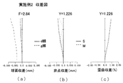
- FIG. 6 is an aberration diagram of Example 2 (spherical aberration (a), astigmatism (b), distortion (c)).
- 6 is a cross-sectional view in the optical axis direction of the imaging lens of Embodiment 3.
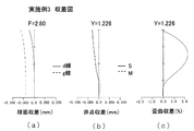
- FIG. FIG. 6 is an aberration diagram of Example 3 (spherical aberration (a), astigmatism (b), distortion (c)).
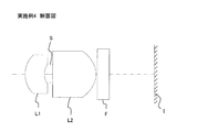
- 6 is a cross-sectional view in the optical axis direction of an imaging lens of Example 4.
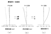
- FIG. FIG. 6 is an aberration diagram of Example 4 (spherical aberration (a), astigmatism (b), distortion (c)).
- FIG. 6 is a cross-sectional view in the optical axis direction of the imaging lens of Example 5.
- FIG. FIG. 6 is an aberration diagram of Example 5 (spherical aberration (a), astigmatism (b), distortion (c)).
- 7 is a cross-sectional view in the optical axis direction of an imaging lens of Example 6.
- FIG. FIG. 10 is an aberration diagram of Example 6 (spherical aberration (a), astigmatism (b), distortion (c)).
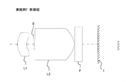
- 10 is a cross-sectional view in the optical axis direction of an imaging lens of Example 7.
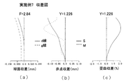
- FIG. FIG. 10 is an aberration diagram of Example 7 (spherical aberration (a), astigmatism (b), distortion (c)).
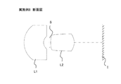
- FIG. 10 is a cross-sectional view in the optical axis direction of the imaging lens of Example 8.
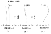
- FIG. 10 is an aberration diagram of Example 8 (spherical aberration (a), astigmatism (b), distortion (c)).
- 10 is a cross-sectional view in the optical axis direction of an imaging lens of Example 9.
- FIG. 10 is an aberration diagram of Example 9 (spherical aberration (a), astigmatism (b), distortion (c)).
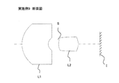
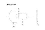
- FIG. 12 is a cross-sectional view in the optical axis direction of the imaging lens of Example 10.
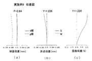
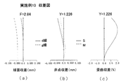
- FIG. 10 is an aberration diagram of Example 10 (spherical aberration (a), astigmatism (b), distortion (c)).
- FIG. 14 is a cross-sectional view in the optical axis direction of the imaging lens of Example 11.
- FIG. 10 is an aberration diagram of Example 11 (spherical aberration (a), astigmatism (b), distortion (c)).
- 14 is a cross-sectional view in the optical axis direction of the imaging lens of Example 12.
- FIG. 10 is an aberration diagram of Example 12 (spherical aberration (a), astigmatism (b), distortion (c)).
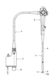
- FIG. 2 shows an overall configuration of an electronic endoscope having the imaging apparatus according to the first embodiment.
- the operation unit 2 is connected to the base end of the flexible insertion unit 1, and a connector 3 connected to a video processor (not shown) can be connected to extend from the vicinity of the upper end of the rear surface of the operation unit 2. It is connected to the tip of the flexible tube 4.
- An objective optical system OS serving as an imaging lens is disposed on the distal end main body 5 connected to the distal end of the insertion portion 1, and an image of a solid-state imaging device 8 such as a CCD type image sensor or a CMOS type image sensor is provided on the image side.
- the surface is arranged.
- Reference numeral 9 denotes a signal cable for transmitting an imaging signal output from the solid-state imaging element 8 to the signal connector unit 10 disposed at the tip of the connector 3.
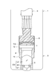
- FIG. 3 shows a tip optical unit portion that holds the objective optical system OS and the solid-state image sensor 8 in the tip body 5 of the electronic endoscope.
- the image sensor holding unit in which the solid-state image sensor 8 is fixed.
- the cylinder 12 has a front end side (lower side in FIG. 3) opened and a rear end side hermetically sealed.
- I is an imaging surface of the solid-state imaging device 8
- CG is a cover glass of the solid-state imaging device 8.
- Various filters are arranged between the objective optical system OS and the cover glass CG depending on the application.
- the lens holding cylinder 13 that holds the objective optical system OS is opened at the back end side (upper side in FIG. 3), and the back end side portion is fitted and fixed to the inner periphery on the front end side of the image sensor holding cylinder 12. Yes.
- the objective optical system OS includes, in order from the object side, a first lens L1 having a negative refractive power and a concave surface facing the image side, an aperture stop S provided on the light shielding member SH, a positive refractive power and an image side.
- the second lens L2 has a convex surface facing the surface.
- F is an attachment part for various optical filters.
- the distal end body 5 of the electronic endoscope shown in FIG. 3 When the distal end body 5 of the electronic endoscope shown in FIG. 3 is inserted into the body of the person to be observed, the reflected light of the part to be observed by a light source (not shown) is incident on the objective optical system OS, and further the solid-state imaging device 8 is converted into an electrical signal by being imaged on the imaging surface I and is input to the signal connector unit 10 via the cable 9 so that an image of the observed portion is displayed on an external monitor.
- the imaging lens of the present invention is applied to a compound eye optical system.
- the compound-eye optical system is an optical system in which a plurality of lens systems (single-eye optical systems) are arranged in an array with respect to one image sensor, and each lens system performs imaging of substantially the same field of view, and each lens.
- the system is usually divided into a field division type that performs imaging of different fields of view.
- the compound eye optical system according to the present invention can be used for any type, but here, from a plurality of images obtained by a plurality of lens systems that face the same direction and have a minute parallax, from individual images A type used for super-resolution processing for outputting one composite image having a higher resolution will be described.
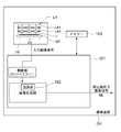
- FIG. 4 schematically shows the imaging apparatus according to the present embodiment.
- the imaging device DU includes an imaging unit LU, an image processing unit 101, a calculation unit 102, a memory 103, and the like.
- the imaging unit LU includes one imaging element SR and a compound-eye optical system LH that forms a plurality of images having minute parallax with respect to the imaging element SR.
- the image sensor SR for example, a solid-state image sensor such as a CCD image sensor or a CMOS image sensor having a plurality of pixels is used.
- the compound-eye optical system LH is provided on the light-receiving surface, that is, the imaging surface I, which is the photoelectric conversion unit of the image sensor SR, an optical image formed by each compound-eye optical system LH is provided. Each image is converted into an electrical signal by the image sensor SR.
- the image composition unit in the image processing unit 101 based on the electrical signals corresponding to the plurality of images sent from the imaging element SR by the arithmetic unit 102, one image data (composition) having a higher resolution from the plurality of images. Image processing is performed so as to obtain an image ML).
- FIG. 5 is a cross-sectional view of the compound eye optical system LH.
- the left side of FIG. 5 is the object side.
- the compound-eye optical system LH is a first unit in which a plurality of (here, nine arranged in 3 rows and 3 columns) object side lenses L1 and a flange portion L1f that connects the object side lenses L1 are integrally formed in order from the object side.
- a second array lens LA2 in which a flange portion L2f for connecting the image side lenses L2 to each other is integrally formed.
- the first array lens LA1 and the second array lens LA2 are each integrally formed of polycarbonate or acrylic, and are bonded with a light shielding member SH interposed therebetween.
- the optical axis X of the object side lens L1 having negative refractive power and having the concave surface facing the image side, the aperture stop S, and the image side lens L2 having positive refractive power and having the convex surface facing the image side coincide with each other.
- a single-eye optical system (imaging lens) is configured.
- the compound eye optical system LH is held by a lens frame (not shown), and this lens frame is fixed to a substrate on which the image sensor SR is mounted.
- D3 thickness on the optical axis of the second lens f: focal length ⁇ Lmax of the entire imaging lens system: effective diameter Yd of the lens having the largest effective diameter Yd: maximum image height
- the imaging lens satisfies the following conditional expression. 0.60 ⁇ f2 / f ⁇ 1.10 (3)
- f2 focal length of the second lens
- f focal length of the entire imaging lens system
- Conditional expression (3) is a conditional expression for appropriately setting the focal length of the second lens.
- the value of conditional expression (3) exceeds the lower limit, the positive refractive power of the second lens is not increased more than necessary, and various aberrations occurring in the second lens can be suppressed.
- the value of conditional expression (3) is less than the upper limit, the positive refractive power of the second lens can be appropriately secured, so that the downsizing of the imaging lens in the optical axis direction can be achieved. Image side telecentric characteristics can be obtained.
- f1 Focal length of the first lens
- f Focal length of the entire imaging lens system
- Conditional expression (4) is a conditional expression for appropriately setting the focal length of the first lens.
- the value of conditional expression (4) exceeds the lower limit, the negative refracting power of the first lens can be adequately secured, so that the wide angle of the imaging lens can be achieved.
- the value of conditional expression (4) is less than the upper limit, the negative refractive power of the first lens does not become too strong, and downsizing of the imaging lens in the optical axis direction can be achieved.
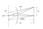
- Conditional expression (5) is a conditional expression for appropriately setting the relationship between the maximum image height of the image plane and the exit pupil position of the imaging lens.
- L2 is the second lens
- I is the image plane
- OA is the optical axis
- EP is the position of the exit pupil.
- Td is the image height on the image plane I
- EXPD is the distance on the optical axis from the exit pupil position EP to the image plane I.
- EXPD is positive when the exit pupil position EP is closer to the object side than the image plane I, and negative when it is closer to the object side than the image plane I.
- Conditional expression (6) is a conditional expression for appropriately setting the radius of curvature of the second lens image side surface. Since the value of conditional expression (6) is less than the upper limit, it is possible to provide a moderate curvature, and thus it is possible to ensure good image side telecentric characteristics. On the other hand, when the value of conditional expression (6) exceeds the lower limit, the curvature is not excessively strong and the possibility of impairing the moldability of the lens can be suppressed, and distortion aberration and image generated on the side surface of the second lens image can be suppressed. Surface curvature can be kept small.
- both surfaces of the first lens and both surfaces of the second lens have aspherical shapes.
- the surface described with “*” after each surface number is a surface having an aspheric shape, and the shape of the aspheric surface has the vertex of the surface as the origin and the X axis in the optical axis direction. (The image side is plus), and the height in the direction perpendicular to the optical axis is h, and is expressed by the following “Expression 1”
- Example 1 shows lens data of Example 1.
- a power of 10 for example, 2.5 ⁇ 10 ⁇ 02
- E for example, 2.5E-02
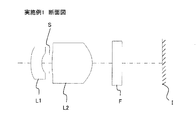
- FIG. 6 is a cross-sectional view of the imaging lens of Example 1.
- L1 is a first lens having negative refractive power and having a concave surface facing the image side
- L2 is a second lens having positive refractive power and having a convex surface facing the image side
- S is an aperture stop
- I Indicates an imaging surface.
- F is a parallel plate assuming an optical low-pass filter, an IR cut filter, a seal glass of a solid-state image sensor, or the like.
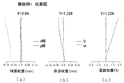
- FIG. 7 is an aberration diagram of Example 1 (spherical aberration (a), astigmatism (b), distortion (c)).
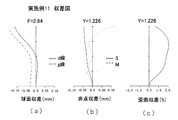
- the solid line represents the amount of spherical aberration with respect to the d-line and the dotted line, respectively, and in the astigmatism diagram, the solid line S represents the sagittal surface and the dotted line M represents the meridional surface (hereinafter the same).
- Example 2 Table 2 shows lens data of the imaging lens of Example 2.
- FIG. 8 is a cross-sectional view of the imaging lens of Example 2.
- L1 is a first lens having negative refractive power and having a concave surface facing the image side
- L2 is a second lens having positive refractive power and having a convex surface facing the image side
- S is an aperture stop
- I Indicates an imaging surface.
- F is a parallel plate assuming an optical low-pass filter, an IR cut filter, a seal glass of a solid-state image sensor, or the like.
- FIG. 9 is an aberration diagram of Example 2 (spherical aberration (a), astigmatism (b), distortion (c)).
- Example 3 shows lens data of the imaging lens of Example 3.
- FIG. 10 is a cross-sectional view of the imaging lens of Example 3.
- L1 is a first lens having negative refractive power and having a concave surface facing the image side
- L2 is a second lens having positive refractive power and having a convex surface facing the image side
- S is an aperture stop
- I Indicates an imaging surface.
- F is a parallel plate assuming an optical low-pass filter, an IR cut filter, a seal glass of a solid-state image sensor, or the like.
- FIG. 11 is an aberration diagram of Example 3 (spherical aberration (a), astigmatism (b), distortion (c)).
- Example 4 shows lens data of the imaging lens of Example 4.
- FIG. 12 is a sectional view of the imaging lens of Example 4.
- L1 is a first lens having negative refractive power and having a concave surface facing the image side
- L2 is a second lens having positive refractive power and having a convex surface facing the image side
- S is an aperture stop
- I Indicates an imaging surface.
- F is a parallel plate assuming an optical low-pass filter, an IR cut filter, a seal glass of a solid-state image sensor, or the like.
- FIG. 13 is an aberration diagram of Example 4 (spherical aberration (a), astigmatism (b), distortion (c)).
- Table 5 shows lens data of the imaging lens of Example 5.
- FIG. 14 is a sectional view of the imaging lens of Example 5.
- L1 is a first lens having negative refractive power and having a concave surface facing the image side
- L2 is a second lens having positive refractive power and having a convex surface facing the image side
- S is an aperture stop
- I Indicates an imaging surface.
- F is a parallel plate assuming an optical low-pass filter, an IR cut filter, a seal glass of a solid-state image sensor, or the like.
- FIG. 15 is an aberration diagram of Example 5 (spherical aberration (a), astigmatism (b), distortion (c)).
- Table 6 shows lens data of the imaging lens of Example 6.
- FIG. 16 is a cross-sectional view of the imaging lens of Example 6.
- L1 is a first lens having negative refractive power and having a concave surface facing the image side
- L2 is a second lens having positive refractive power and having a convex surface facing the image side
- S is an aperture stop
- I Indicates an imaging surface.
- F is a parallel plate assuming an optical low-pass filter, an IR cut filter, a seal glass of a solid-state image sensor, or the like.
- FIG. 17 is an aberration diagram of Example 6 (spherical aberration (a), astigmatism (b), distortion (c)).
- Table 7 shows lens data of the imaging lens of Example 7.
- FIG. 18 is a cross-sectional view of the imaging lens of Example 7.
- L1 is a first lens having negative refractive power and having a concave surface facing the image side
- L2 is a second lens having positive refractive power and having a convex surface facing the image side
- S is an aperture stop
- I Indicates an imaging surface.
- F is a parallel plate assuming an optical low-pass filter, an IR cut filter, a seal glass of a solid-state image sensor, or the like.
- FIG. 19 is an aberration diagram of Example 7 (spherical aberration (a), astigmatism (b), distortion (c)).
- Table 8 shows lens data of the imaging lens of Example 8.
- FIG. 20 is a sectional view of the imaging lens of Example 8.
- L1 is a first lens having negative refractive power and having a concave surface facing the image side
- L2 is a second lens having positive refractive power and having a convex surface facing the image side
- S is an aperture stop
- I Indicates an imaging surface.
- FIG. 20 is an aberration diagram of Example 8 (spherical aberration (a), astigmatism (b), distortion (c)).
- Example 9 shows lens data of the imaging lens of Example 9.
- FIG. 22 is a sectional view of the imaging lens of Example 9.
- L1 is a first lens having negative refractive power and having a concave surface facing the image side
- L2 is a second lens having positive refractive power and having a convex surface facing the image side
- S is an aperture stop
- I Indicates an imaging surface.
- FIG. 23 is an aberration diagram of Example 9 (spherical aberration (a), astigmatism (b), distortion (c)).
- Table 10 shows lens data of the imaging lens of Example 10.
- FIG. 24 is a cross-sectional view of the imaging lens of Example 10.
- L1 is a first lens having negative refractive power and having a concave surface facing the image side
- L2 is a second lens having positive refractive power and having a convex surface facing the image side
- S is an aperture stop
- I Indicates an imaging surface.
- FIG. 25 is an aberration diagram of Example 10 (spherical aberration (a), astigmatism (b), distortion (c)).
- Table 11 shows lens data of the imaging lens of Example 11.
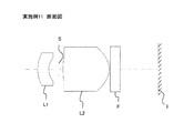
- FIG. 26 is a cross-sectional view of the imaging lens of Example 11.
- L1 is a first lens having negative refractive power and having a concave surface facing the image side
- L2 is a second lens having positive refractive power and having a convex surface facing the image side
- S is an aperture stop
- I Indicates an imaging surface.
- F is a parallel plate assuming an optical low-pass filter, an IR cut filter, a seal glass of a solid-state image sensor, or the like.
- FIG. 27 is an aberration diagram of Example 11 (spherical aberration (a), astigmatism (b), distortion (c)).
- Example 12 Table 12 shows lens data of the imaging lens of Example 12.
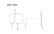
- FIG. 28 is a cross-sectional view of the imaging lens of Example 12.
- L1 is a first lens having negative refractive power and having a concave surface facing the image side
- L2 is a second lens having positive refractive power and having a convex surface facing the image side
- S is an aperture stop
- I Indicates an imaging surface.
- F is a parallel plate assuming an optical low-pass filter, an IR cut filter, a seal glass of a solid-state image sensor, or the like.
- FIG. 29 is an aberration diagram of Example 12 (spherical aberration (a), astigmatism (b), distortion (c)).
- Table 13 shows the values of each example corresponding to each conditional expression.
- the imaging lens according to the present invention is suitable for an imaging apparatus using an electronic endoscope or a compound-eye optical system as described above, but is not limited thereto.
- the imaging lens is applied to an imaging apparatus for a small portable terminal. You may do it.
Landscapes
- Physics & Mathematics (AREA)
- Health & Medical Sciences (AREA)
- Life Sciences & Earth Sciences (AREA)
- Surgery (AREA)
- Optics & Photonics (AREA)
- Engineering & Computer Science (AREA)
- Biomedical Technology (AREA)
- Molecular Biology (AREA)
- Pathology (AREA)
- Nuclear Medicine, Radiotherapy & Molecular Imaging (AREA)
- Biophysics (AREA)
- Heart & Thoracic Surgery (AREA)
- Medical Informatics (AREA)
- Radiology & Medical Imaging (AREA)
- Animal Behavior & Ethology (AREA)
- General Health & Medical Sciences (AREA)
- Public Health (AREA)
- Veterinary Medicine (AREA)
- Astronomy & Astrophysics (AREA)
- General Physics & Mathematics (AREA)
- Multimedia (AREA)
- Lenses (AREA)
Abstract
従来タイプより径方向に十分な小型化が可能でありながらも、撮像面周辺部への主光線入射角度が小さく抑えられ、諸収差が良好に補正された、2枚構成の撮像レンズ及び撮像装置を提供する。この撮像レンズは、物体側より順に、負の屈折力を有し像側に凹面を向けた第1レンズ、開口絞り、正の屈折力を有し像側に凸面を向けた第2レンズ、からなり、以下の条件式を満足する。 0.74<D3/f<1.50 (1) 0.68<ΦLmax/2Yd<1.70 (2) ただし、D3:前記第2レンズの光軸上の厚み f:撮像レンズ全系の焦点距離 ΦLmax:最も有効径の大きなレンズの有効径 Yd:最大像高
Description
本発明は、CCD型イメージセンサあるいはCMOS型イメージセンサ等の固体撮像素子を用いた撮像装置、及びそれに用いる撮像レンズに関する。
近年、CCD(Charge Coupled Device)型イメージセンサあるいはCMOS(Complementary Metal Oxide Semiconductor)型イメージセンサ等の固体撮像素子を用いた撮像素子の高性能化、小型化に伴い、このような固体撮像素子を用いた撮像装置が,携帯端末等に留まらず、更に広範な分野で用いられるようになってきた。また、これらの撮像装置に搭載される撮像レンズには、さらなる小型化への要求が高まっている。
例えば、被観察者の体内へと挿入される医療用内視鏡に内蔵された撮像装置に使用される撮像レンズには、被観察者の負担軽減のため径方向の小型化の要求が特に高いという傾向がある。また、固体撮像素子に関しても、携帯端末用のように大量生産される用途では専用の設計が可能になるから、撮像面の最周辺部への主光線入射角度が30°程度まで許容される場合があるのに対し、医療用内視鏡のように細い管内に配置するために、汎用の固体撮像素子を使用せざるを得ない場合がある。この場合、それに対応して撮像面への主光線入射角度も小さく抑えた撮像レンズを設計する必要がある。更に、撮像レンズの画角に関しても、近距離でも広い範囲の被写体を観察することが望まれるという観点から、撮像レンズの広角化の要求も高まっている。
これに対し、撮像レンズの広角化と小型化を両立するために、負の屈折力を有する第1レンズ、正の屈折力を有する第2レンズの順で配置した2枚構成の撮像レンズが開示されている(例えば、特許文献1、2参照)。
しかしながら、特許文献1に記載の撮像レンズは、第1レンズが第2レンズに比べて大きく、同時に第1レンズが撮像面サイズよりも大きくなっている。このような撮像レンズの場合、撮像装置に組み込んだ場合の径方向のサイズが第1レンズの有効径で決定されることとなり、撮像装置の径方向の大型化を免れない。
また、特許文献2に記載の撮像レンズは、第1レンズと第2レンズの有効径は共に撮像面サイズよりも小さくなってはいるものの、撮像面周辺部への主光線入射角度が20°超と大きく、汎用の固体撮像素子を使用する場合にはシェーディング等の不具合が発生する可能性があり好ましくない。
本発明は、このような問題点に鑑みてなされたものであり、従来タイプより径方向に十分な小型化が可能でありながらも、撮像面周辺部への主光線入射角度が小さく抑えられ、諸収差が良好に補正された、2枚構成の撮像レンズ及び撮像装置を提供することを目的とする。
上述した目的のうち少なくとも一つを実現するために、本発明の一側面を反映した撮像レンズは、固体撮像素子の光電変換部に被写体像を結像させるための撮像レンズであって、物体側より順に、
負の屈折力を有し像側に凹面を向けた第1レンズ、
開口絞り、
正の屈折力を有し像側に凸面を向けた第2レンズ、からなり、
以下の条件式を満足することを特徴とする撮像レンズ。
0.74<D3/f<1.50 (1)
0.68<ΦLmax/2Yd<1.70 (2)
ただし、
D3:前記第2レンズの光軸上の厚み
f:撮像レンズ全系の焦点距離
ΦLmax:最も有効径の大きなレンズの有効径
Yd:最大像高
負の屈折力を有し像側に凹面を向けた第1レンズ、
開口絞り、
正の屈折力を有し像側に凸面を向けた第2レンズ、からなり、
以下の条件式を満足することを特徴とする撮像レンズ。
0.74<D3/f<1.50 (1)
0.68<ΦLmax/2Yd<1.70 (2)
ただし、
D3:前記第2レンズの光軸上の厚み
f:撮像レンズ全系の焦点距離
ΦLmax:最も有効径の大きなレンズの有効径
Yd:最大像高
強い正の屈折力を有する第2レンズの前方に、比較的屈折力の弱い負の第1レンズを配置する、所謂レトロフォーカスタイプの撮像レンズとすることで、撮像レンズ全長の小型化と広角化を両立している。また、開口絞りを第1レンズと第2レンズの間に配置することで、開口絞りに対して、第1レンズと第2レンズをコンセントリックな配置とすることができるので、収差補正には有利な構成となる。
条件式(1)は、収差補正を行いつつ、撮像レンズの小型化と良好な像側テレセントリック特性を得るための条件式である。条件式(1)の値が下限を上回ることで、第2レンズの厚みを適度に持たせ、第2レンズの屈折力を適度に確保することができ、良好な像側テレセントリック特性を得ることができる。また、第2レンズの厚みが大きいと、第2レンズ像側面を通過する各像高ごとの光線が異なる位置を通過することになるので、像面湾曲の補正に有利となる。一方、条件式(1)の値が上限を下回ることで、必要以上に第2レンズの厚みが大きくなりすぎず、撮像レンズの光軸方向の小型化を達成できる。
条件式(2)は、撮像レンズにより形成される画像の最大像高に対する、最も有効径の大きなレンズの有効径との比を適切に設定するための条件式である。条件式(2)の値が上限を下回ることで、形成される画像の最大像高に対しレンズ径が大きくなりすぎず、撮像装置全系の径方向のサイズを小さく抑えることができる。一方、条件式(2)の値が下限を上回ることで、撮像レンズの有効径が固体撮像素子に対して小さくなりすぎないようにできる。撮像レンズの有効径が最大像高に対して小さくなると、撮像レンズから出射してくる光線角度はその分大きくなってくる。このため、良好な像側テレセントリック特性を得るためには、撮像レンズの有効径が最大像高に対して小さくなりすぎないことが重要となる。
上記撮像レンズは、実質的に屈折力を有しないレンズを有していてもよい。つまり、上記構成に、実質的にパワーを持たないレンズを付与した場合でも本発明の適用範囲内である。
本撮像装置は、上述の撮像レンズと、前記撮像レンズにより形成された画像を光電変換する撮像素子を有することを特徴とする。
上記撮像装置において、前記撮像レンズが光軸直交方向にアレイ状に配置され、前記撮像素子は前記撮像レンズの各々が形成する画像を光電変換するように構成できる。
本発明によれば、従来タイプより径方向に十分な小型化が可能でありながらも、撮像面周辺部への主光線入射角度が小さく抑えられ、諸収差が良好に補正された、2枚構成の撮像レンズ及び撮像装置を提供することができる。
以下、本発明の実施形態を、図面を参照して説明する。図2は第1の実施形態にかかる撮像装置を有する電子内視鏡の全体構成を示している。図2において、可撓性の挿入部1の基端に操作部2が連結され、図示されていないビデオプロセッサに接続されるコネクタ3が、操作部2の後面上端部近傍から延出する接続可撓管4の先端に連結されている。
挿入部1の先端に連結された先端部本体5には、撮像レンズとしての対物光学系OSが配置され、その像側にはCCD型イメージセンサ、CMOS型イメージセンサ等の固体撮像素子8の撮像面が配置されている。9は、固体撮像素子8から出力される撮像信号を、コネクタ3の先端に配置された信号コネクタ部10に伝送するための信号ケーブルである。
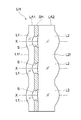
図3は、電子内視鏡の先端部本体5内において対物光学系OSと固体撮像素子8とを保持する先端光学ユニット部分を示しており、内部に固体撮像素子8が固定された撮像素子保持筒12は、先端側(図3において下方側)が開放されて後端側が気密に封止されている。Iは固体撮像素子8の撮像面、CGは固体撮像素子8のカバーガラスである。なお対物光学系OSとカバーガラスCGの間に、用途に応じ各種フィルタが配置される。
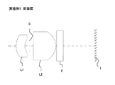
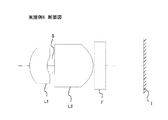
対物光学系OSを保持するレンズ保持筒13は、奥端側(図3において上方側)が開放されてその奥端側部分が撮像素子保持筒12の先端側の内周に嵌挿固定されている。対物光学系OSは、物体側より順に、負の屈折力を有し像側に凹面を向けた第1レンズL1、遮光部材SHに設けられた開口絞りS、正の屈折力を有し像側に凸面を向けた第2レンズL2、から構成されている。Fは、各種光学フィルタの取り付け部である。
図3に示す電子内視鏡の先端部本体5を被観察者の体内へと挿入したときに、不図示の光源による被観察部の反射光が対物光学系OSに入射し、更に固体撮像素子8の撮像面Iで結像することによって電気信号に変換され、ケーブル9を介して信号コネクタ部10に入力され、被観察部の像が外部のモニタに表示されるようになっている。
次に、第2の実施形態にかかる撮像装置等を説明する。本実施形態では、本発明の撮像レンズを複眼光学系に適用したものである。複眼光学系は、1つの撮像素子に対して複数のレンズ系(個眼光学系)がアレイ状に配置された光学系であり、各レンズ系がほぼ同じ視野の撮像を行うタイプと、各レンズ系が異なる視野の撮像を行う視野分割タイプと、に通常分けられる。本発明に係る複眼光学系は、いずれのタイプにも用いることができるが、ここでは同じ方向を向き、かつ、微小に視差を有する複数のレンズ系によって得られる複数の像から、個々の像よりも高い解像度を持つ1枚の合成画像を出力する超解像処理に用いられるタイプについて説明する。
図4に本実施形態にかかる撮像装置を模式的に示す。図4に示すように、撮像装置DUは、撮像ユニットLU、画像処理部101、演算部102、メモリー103等を有している。そして、撮像ユニットLUは、1つの撮像素子SRと、その撮像素子SRに対して、互いに微小な視差を有する複数の像を結像する複眼光学系LHと、を有している。撮像素子SRとしては、例えば複数の画素を有するCCD型イメージセンサ、CMOS型イメージセンサ等の固体撮像素子が用いられる。撮像素子SRの光電変換部である受光面すなわち撮像面I上には、被写体の光学像が形成されるように複眼光学系LHが設けられているので、各複眼光学系LHによって形成された光学像は、それぞれ撮像素子SRによって電気的な信号に変換される。画像処理部101内の画像合成部においては、演算部102により撮像素子SRから送られる複数の画像に相当する電気信号に基づいて、複数枚の画像からより解像度の高い1枚の画像データ(合成画像ML)を得るように画像処理を実行する。
図5は、複眼光学系LHの断面図である。図5の左方が物体側である。複眼光学系LHは、物体側から順に、複数(ここでは3行3列に並べた9個)の物体側レンズL1と、物体側レンズL1同士をつなげるフランジ部L1fが一体に形成された第1アレイレンズLA1と、複数(ここでは3行3列に並べた9個)の開口絞りSを有する遮光部材SHと、複数(ここでは3行3列に並べた9個)の像側レンズL2と、像側レンズL2同士をつなげるフランジ部L2fが一体に形成された第2アレイレンズLA2と、を有する。第1アレイレンズLA1と第2アレイレンズLA2は、それぞれポリカーボネート又はアクリル等で一体に成形され、遮光部材SHを介在させて接着されている。負の屈折力を有し像側に凹面を向けた物体側レンズL1と、開口絞りSと、正の屈折力を有し像側に凸面を向けた像側レンズL2の光軸Xは一致しており、これにより個眼光学系(撮像レンズ)を構成する。
複眼光学系LHは不図示の鏡枠に保持されており、この鏡枠は撮像素子SRが実装された基板に固定されている。
図3の第1レンズL1と、開口絞りSと、第2レンズL2とから構成される撮像レンズ(対物光学系OS)において次の条件式(1)(2)を満足する。また、図5の複眼光学系LHにおいても同様である。
0.74<D3/f<1.50 (1)
0.68<ΦLmax/2Yd<1.70 (2)
ただし、
D3:前記第2レンズの光軸上の厚み
f:撮像レンズ全系の焦点距離
ΦLmax:最も有効径の大きなレンズの有効径
Yd:最大像高
0.68<ΦLmax/2Yd<1.70 (2)
ただし、
D3:前記第2レンズの光軸上の厚み
f:撮像レンズ全系の焦点距離
ΦLmax:最も有効径の大きなレンズの有効径
Yd:最大像高
上記撮像レンズは、以下の条件式を満足することが好ましい。
0.60<f2/f<1.10 (3)
ただし、
f2:前記第2レンズの焦点距離
f:撮像レンズ全系の焦点距離
0.60<f2/f<1.10 (3)
ただし、
f2:前記第2レンズの焦点距離
f:撮像レンズ全系の焦点距離
条件式(3)は、第2レンズの焦点距離を適切に設定するための条件式である。条件式(3)の値が下限を上回ることで、必要以上に第2レンズの正の屈折力が強くなりすぎず、第2レンズで発生する諸収差を抑えることができる。一方、条件式(3)の値が上限を下回ることで、適度に第2レンズの正の屈折力を確保することができるので、撮像レンズの光軸方向の小型化を達成でき、また良好な像側テレセントリック特性を得ることができる。
また、以下の条件式を満足することが好ましい。
-5.00<f1/f<-0.80 (4)
ただし、
f1:前記第1レンズの焦点距離
f:撮像レンズ全系の焦点距離
-5.00<f1/f<-0.80 (4)
ただし、
f1:前記第1レンズの焦点距離
f:撮像レンズ全系の焦点距離
条件式(4)は、第1レンズの焦点距離を適切に設定するための条件式である。条件式(4)の値が下限を上回ることで、適度に第1レンズの負の屈折力を確保できるので、撮像レンズの広角化を達成できる。一方、条件式(4)の値が上限を下回ることで、第1レンズの負の屈折力が強くなりすぎず、撮像レンズの光軸方向の小型化を達成することができる。
また、以下の条件式を満足することが好ましい。
-0.20<Yd/EXPD<0.30 (5)
ただし、
Yd:最大像高
EXPD:射出瞳位置から像面までの光軸上の距離
-0.20<Yd/EXPD<0.30 (5)
ただし、
Yd:最大像高
EXPD:射出瞳位置から像面までの光軸上の距離
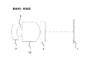
条件式(5)は、像面の最大像高と撮像レンズの射出瞳位置の関係を適切に設定するための条件式である。図1において、L2は第2レンズ、Iは像面、OAは光軸、EPは射出瞳の位置である。又、Tdは像面I上の像高であり、EXPDは射出瞳の位置EPから像面Iまでの光軸上の距離である。但し、EXPDは、射出瞳の位置EPが像面Iよりも物体側にあるときは正とし、像面Iよりも反物体側にあるときを負とする。
ここで、近軸的には像面Iへ入射する全ての光線は射出瞳から出射してくる。つまり、像高を射出瞳から像面までの距離で割るということは、射出瞳の光軸上の位置から像面へ入射する光線CRの正接(tanθ)を表すこととなる。したがって、条件式(5)の値が下限を上回ることで、像面への光線の入射角度が小さくなりすぎず、像面サイズに対しての、撮像レンズの径方向の大きさを小さく抑えることができるようになる。一方、条件式(5)の値が上限を下回ることで、像面への光線の入射角度が大きくなりすぎず、良好な像側テレセントリック特性を得ることができる。
また、以下の条件式を満足することが好ましい。
-0.70<r4/f<-0.35 (6)
ただし、
r4:前記第2レンズ像側面の曲率半径
f:撮像レンズ全系の焦点距離
-0.70<r4/f<-0.35 (6)
ただし、
r4:前記第2レンズ像側面の曲率半径
f:撮像レンズ全系の焦点距離
条件式(6)は、第2レンズ像側面の曲率半径を適切に設定するための条件式である。条件式(6)の値が上限を下回ることで、適度に曲率を持たせることができるので、良好な像側テレセントリック特性を確保することができる。一方、条件式(6)の値が下限を上回ることで、必要以上に曲率が強くなりすぎず、レンズの成形性を損なう恐れを抑制できると共に、第2レンズ像側面で発生する歪曲収差や像面湾曲を小さく抑えることができるようになる。
また、第1レンズの両面と第2レンズの両面が非球面形状を有することが好ましい。全ての面を非球面形状とすることで、2枚構成と簡素な構成でありながらも、周辺部まで良好に収差補正のなされた撮像レンズを得ることができる。
[実施例]
以下、上述した実施形態に用いることができる撮像レンズの実施例を示す。各実施例に使用する記号は下記の通りである。特に示さない限り、寸法に関する単位はmmである。
f :撮像レンズ全系の焦点距離
fB:バックフォーカス
F :Fナンバー
Yd:最大像高
ENTP:入射瞳位置(第1面から入射瞳位置までの距離)
EXTP:射出瞳位置(最終面から射出瞳位置までの距離)
H1 :前側主点位置(第1面から前側主点位置までの距離)
H2 :後側主点位置(最終面から後側主点位置までの距離)
R :曲率半径
D :軸上面間隔
Nd:レンズ材料のd線に対する屈折率
νd:レンズ材料のd線に対するアッベ数
以下、上述した実施形態に用いることができる撮像レンズの実施例を示す。各実施例に使用する記号は下記の通りである。特に示さない限り、寸法に関する単位はmmである。
f :撮像レンズ全系の焦点距離
fB:バックフォーカス
F :Fナンバー
Yd:最大像高
ENTP:入射瞳位置(第1面から入射瞳位置までの距離)
EXTP:射出瞳位置(最終面から射出瞳位置までの距離)
H1 :前側主点位置(第1面から前側主点位置までの距離)
H2 :後側主点位置(最終面から後側主点位置までの距離)
R :曲率半径
D :軸上面間隔
Nd:レンズ材料のd線に対する屈折率
νd:レンズ材料のd線に対するアッベ数
各実施例において、各面番号の後に「*」が記載されている面が非球面形状を有する面であり、非球面の形状は、面の頂点を原点とし、光軸方向にX軸をとり(像側をプラス)、光軸と垂直方向の高さをhとして以下の「数1」で表す。

Ai:i次の非球面係数
R :曲率半径
K :円錐定数
なお、特許請求の範囲及び実施例に記載の近軸曲率半径の意味合いについて、実際のレンズ測定の場面においては、レンズ中央近傍(具体的には、レンズ外径に対して10%以内の中央領域)での形状測定値を最小自乗法でフィッティングした際の近似曲率半径を近軸曲率半径であるとみなすことができる。また、例えば2次の非球面係数を使用した場合には、非球面定義式の基準曲率半径に2次の非球面係数も勘案した曲率半径を近軸曲率半径とみなすことができる。(例えば参考文献として、松居吉哉著「レンズ設計法」(共立出版株式会社)のP41~42を参照のこと)
(実施例1)
実施例1のレンズデータを表1に示す。なお、これ以降(表のレンズデータを含む)において、10のべき乗数(たとえば2.5×10-02)を、E(たとえば2.5E-02)を用いて表すものとする。
実施例1のレンズデータを表1に示す。なお、これ以降(表のレンズデータを含む)において、10のべき乗数(たとえば2.5×10-02)を、E(たとえば2.5E-02)を用いて表すものとする。
[表1]
実施例 1
f=2.28mm fB=2.98mm F=2.84 2Yd=2.453mm
ENTP=0.74mm EXTP=-4.87mm H1=2.36mm H2=0.7mm
面番号 R(mm) D(mm) Nd νd 有効半径(mm)
1* 3.582 0.549 1.58310 59.4 0.85
2* 1.113 0.375 0.50
3(絞り) ∞ 0.136 0.43
4* 13.952 2.000 1.58310 59.4 0.55
5* -1.186 0.050 1.04
6 ∞ 0.500 1.51630 64.1 1.08
7 ∞ 1.10
非球面係数
第1面 第4面
K= 0.50971E+01 K= 0.49998E+02
A4= 0.33109E+00 A4= 0.72939E-01
A6= -0.11308E+01 A6= 0.13359E+01
A8= 0.62085E+01 A8= -0.95070E+01
A10= -0.20313E+02 A10= 0.31063E+02
A12= 0.37395E+02 A12= 0.19642E+02
A14= -0.35734E+02 A14= -0.25232E+03
A16= 0.13787E+02 A16= -0.34765E+03
A18= 0.00000E+00 A18= 0.31505E+04
A20= 0.00000E+00 A20= -0.39197E+04
第2面 第5面
K= 0.31951E+01 K= -0.87221E+00
A4= 0.40609E+00 A4= -0.15699E-02
A6= 0.14098E+01 A6= -0.29701E-01
A8= -0.17577E+02 A8= 0.87492E-01
A10= 0.89269E+02 A10= -0.62487E-01
A12= -0.17467E+03 A12= -0.12745E+00
A14= -0.18841E+02 A14= 0.29602E+00
A16= 0.13583E+01 A16= -0.20426E+00
A18= 0.00000E+00 A18= 0.38298E-01
A20= 0.00000E+00 A20= 0.74203E-02
単レンズデータ
レンズ 始面 焦点距離(mm)
1 1 -3.017
2 4 1.971
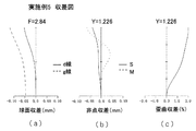
図6は実施例1の撮像レンズの断面図である。図中L1は、負の屈折力を有し像側に凹面を向けた第1レンズ、L2は、正の屈折力を有し像側に凸面を向けた第2レンズ、Sは開口絞り、Iは撮像面を示す。また、Fは光学的ローパスフィルタやIRカットフィルタ、固体撮像素子のシールガラス等を想定した平行平板である。図7は実施例1の収差図(球面収差(a)、非点収差(b)、歪曲収差(c))である。ここで、球面収差図において、実線はd線、点線はg線に対する球面収差量をそれぞれ表し、非点収差図において、実線Sはサジタル面、点線Mはメリディオナル面を表す(以下、同じ)。
(実施例2)
実施例2の撮像レンズのレンズデータを、表2に示す。
実施例2の撮像レンズのレンズデータを、表2に示す。
[表2]
実施例 2
f=2.28mm fB=2.97mm F=2.84 2Yd=2.453mm
ENTP=0.75mm EXTP=-4.88mm H1=2.36mm H2=0.69mm
面番号 R(mm) D(mm) Nd νd 有効半径(mm)
1* 2.432 0.559 1.75000 27.0 0.82
2* 0.968 0.371 0.49
3(絞り) ∞ 0.157 0.42
4* 6.978 1.939 1.58310 59.4 0.58
5* -1.165 0.050 1.04
6 ∞ 0.500 1.51630 64.1 1.08
7 ∞ 1.10
非球面係数
第1面 第4面
K= -0.38776E+02 K= 0.49310E+02
A4= 0.54937E+00 A4= 0.34152E-01
A6= -0.15676E+01 A6= 0.14487E+01
A8= 0.67492E+01 A8= -0.10459E+02
A10= -0.20595E+02 A10= 0.31589E+02
A12= 0.37395E+02 A12= 0.25308E+02
A14= -0.35734E+02 A14= -0.24472E+03
A16= 0.13787E+02 A16= -0.38104E+03
A18= 0.00000E+00 A18= 0.30063E+04
A20= 0.00000E+00 A20= -0.35851E+04
第2面 第5面
K= 0.16407E+01 K= -0.86385E+00
A4= 0.25752E+00 A4= -0.33855E-02
A6= 0.23435E+01 A6= -0.24974E-01
A8= -0.23798E+02 A8= 0.82448E-01
A10= 0.10864E+03 A10= -0.60869E-01
A12= -0.17467E+03 A12= -0.12280E+00
A14= -0.18841E+02 A14= 0.29365E+00
A16= 0.13583E+01 A16= -0.20595E+00
A18= 0.00000E+00 A18= 0.41839E-01
A20= 0.00000E+00 A20= 0.59069E-02
単レンズデータ
レンズ 始面 焦点距離(mm)
1 1 -2.562
2 4 1.876
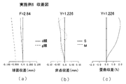
図8は実施例2の撮像レンズの断面図である。図中L1は、負の屈折力を有し像側に凹面を向けた第1レンズ、L2は、正の屈折力を有し像側に凸面を向けた第2レンズ、Sは開口絞り、Iは撮像面を示す。また、Fは光学的ローパスフィルタやIRカットフィルタ、固体撮像素子のシールガラス等を想定した平行平板である。図9は実施例2の収差図(球面収差(a)、非点収差(b)、歪曲収差(c))である。
(実施例3)
実施例3の撮像レンズのレンズデータを、表3に示す。
実施例3の撮像レンズのレンズデータを、表3に示す。
[表3]
実施例 3
f=2.27mm fB=0.55mm F=2.8 2Yd=2.453mm
ENTP=3.2mm EXTP=8.47mm H1=6.11mm H2=-1.72mm
面番号 R(mm) D(mm) Nd νd 有効半径(mm)
1* 1.077 1.071 1.58310 59.4 1.23
2* 0.569 0.999 0.67
3(絞り) ∞ 0.108 0.30
4* 2.047 3.000 1.58310 59.4 0.37
5* -0.960 0.500 1.15
6 ∞ 0.300 1.51630 64.1 1.50
7 ∞ 1.50
非球面係数
第1面 第4面
K= -0.79175E+00 K= -0.62656E+01
A4= 0.25051E-01 A4= 0.13553E-01
A6= 0.45312E-01 A6= 0.27201E+00
A8= -0.50358E-01 A8= -0.49665E+01
A10= 0.44294E-01 A10= 0.51254E+02
A12= -0.16317E-01 A12= -0.16776E+03
第2面 第5面
K= -0.60465E+00 K= -0.66381E+00
A4= -0.40339E-01 A4= 0.14331E+00
A6= 0.99058E-01 A6= -0.27488E-01
A8= 0.10162E+00 A8= 0.22075E-01
A10= -0.23472E+01 A10= -0.64318E-02
A12= 0.72086E+00 A12= 0.21115E-02
単レンズデータ
レンズ 始面 焦点距離(mm)
1 1 -9.322
2 4 1.772
図10は実施例3の撮像レンズの断面図である。図中L1は、負の屈折力を有し像側に凹面を向けた第1レンズ、L2は、正の屈折力を有し像側に凸面を向けた第2レンズ、Sは開口絞り、Iは撮像面を示す。また、Fは光学的ローパスフィルタやIRカットフィルタ、固体撮像素子のシールガラス等を想定した平行平板である。図11は実施例3の収差図(球面収差(a)、非点収差(b)、歪曲収差(c))である。
(実施例4)
実施例4の撮像レンズのレンズデータを、表4に示す。
実施例4の撮像レンズのレンズデータを、表4に示す。
[表4]
実施例 4
f=2.37mm fB=1.85mm F=2.84 2Yd=2.452mm
ENTP=1.05mm EXTP=-4.92mm H1=2.59mm H2=-0.52mm
面番号 R(mm) D(mm) Nd νd 有効半径(mm)
1* 1.227 0.788 1.63470 23.9 0.83
2* 0.727 0.238 0.39
3(絞り) ∞ 0.094 0.32
4* 34.381 1.780 1.54470 56.0 0.42
5* -0.936 0.050 0.99
6 ∞ 0.500 1.51630 64.1 1.07
7 ∞ 1.11
非球面係数
第1面 第4面
K= -0.57915E+00 K= 0.50000E+02
A4= 0.17289E+00 A4= -0.13591E+00
A6= -0.91471E+00 A6= 0.37831E+01
A8= 0.60516E+01 A8= -0.23921E+02
A10= -0.20226E+02 A10= -0.24724E+02
A12= 0.37382E+02 A12= 0.59255E+03
A14= -0.35451E+02 A14= 0.29807E+04
A16= 0.13550E+02 A16= -0.14320E+05
A18= 0.00000E+00 A18= -0.13446E+06
A20= 0.00000E+00 A20= 0.53922E+06
第2面 第5面
K= 0.11579E+01 K= -0.82532E+00
A4= 0.89405E-01 A4= -0.11207E-01
A6= -0.14906E+01 A6= -0.76539E-01
A8= 0.84421E+01 A8= 0.12650E+00
A10= 0.94267E+00 A10= -0.96137E-01
A12= -0.15809E+03 A12= -0.14434E+00
A14= -0.16643E+02 A14= 0.31026E+00
A16= 0.11143E+02 A16= -0.19203E+00
A18= 0.00000E+00 A18= 0.36866E-01
A20= 0.00000E+00 A20= 0.21589E-02
単レンズデータ
レンズ 始面 焦点距離(mm)
1 1 -7.269
2 4 1.704
図12は実施例4の撮像レンズの断面図である。図中L1は、負の屈折力を有し像側に凹面を向けた第1レンズ、L2は、正の屈折力を有し像側に凸面を向けた第2レンズ、Sは開口絞り、Iは撮像面を示す。また、Fは光学的ローパスフィルタやIRカットフィルタ、固体撮像素子のシールガラス等を想定した平行平板である。図13は実施例4の収差図(球面収差(a)、非点収差(b)、歪曲収差(c))である。
(実施例5)
実施例5の撮像レンズのレンズデータを、表5に示す。
実施例5の撮像レンズのレンズデータを、表5に示す。
[表5]
実施例 5
f=2.28mm fB=2.42mm F=2.84 2Yd=2.452mm
ENTP=0.95mm EXTP=-6.03mm H1=2.61mm H2=0.14mm
面番号 R(mm) D(mm) Nd νd 有効半径(mm)
1* 1.589 0.661 1.63470 23.9 0.85
2* 0.855 0.359 0.48
3(絞り) ∞ 0.291 0.36
4 ∞ 1.710 1.54470 56.0 0.60
5* -1.012 0.050 1.08
6 ∞ 0.500 1.51630 64.1 1.14
7 ∞ 1.16
非球面係数
第1面 第5面
K= -0.54096E+00 K= -0.94052E+00
A4= 0.18655E+00 A4= -0.14659E-01
A6= -0.10099E+01 A6= -0.68544E-01
A8= 0.61939E+01 A8= 0.12236E+00
A10= -0.20394E+02 A10= -0.81484E-01
A12= 0.37382E+02 A12= -0.14037E+00
A14= -0.35451E+02 A14= 0.30193E+00
A16= 0.13550E+02 A16= -0.20134E+00
A18= 0.36948E-01
A20= 0.64646E-02
第2面
A4= 0.15026E+00
A6= -0.33589E+01
A8= 0.13432E+02
A10= -0.73415E+01
A12= -0.15809E+03
A14= -0.16643E+02
A16= 0.11143E+02
単レンズデータ
レンズ 始面 焦点距離(mm)
1 1 -4.481
2 4 1.857
図14は実施例5の撮像レンズの断面図である。図中L1は、負の屈折力を有し像側に凹面を向けた第1レンズ、L2は、正の屈折力を有し像側に凸面を向けた第2レンズ、Sは開口絞り、Iは撮像面を示す。また、Fは光学的ローパスフィルタやIRカットフィルタ、固体撮像素子のシールガラス等を想定した平行平板である。図15は実施例5の収差図(球面収差(a)、非点収差(b)、歪曲収差(c))である。
(実施例6)
実施例6の撮像レンズのレンズデータを、表6に示す。
実施例6の撮像レンズのレンズデータを、表6に示す。
[表6]
実施例 6
f=2.25mm fB=1.65mm F=2.84 2Yd=2.452mm
ENTP=0.98mm EXTP=-4.86mm H1=2.45mm H2=-0.6mm
面番号 R(mm) D(mm) Nd νd 有効半径(mm)
1* 1.195 0.748 1.84700 23.8 0.78
2* 0.699 0.220 0.37
3(絞り) ∞ 0.094 0.29
4* 19.614 1.686 1.58310 59.4 0.39
5* -0.912 0.050 0.93
6 ∞ 0.500 1.51630 64.1 1.00
7 ∞ 1.04
非球面係数
第1面 第4面
K= -0.78388E+00 K= -0.50000E+02
A4= 0.18592E+00 A4= -0.57894E-01
A6= -0.89726E+00 A6= 0.29622E+01
A8= 0.60534E+01 A8= -0.21609E+02
A10= -0.20286E+02 A10= 0.43833E+01
A12= 0.37375E+02 A12= 0.65754E+03
A14= -0.35049E+02 A14= 0.22851E+04
A16= 0.13134E+02 A16= -0.22342E+05
A18= 0.00000E+00 A18= -0.16250E+06
A20= 0.00000E+00 A20= 0.88769E+06
第2面 第5面
K= 0.29327E+00 K= -0.79607E+00
A4= 0.43859E+00 A4= -0.87308E-02
A6= -0.17969E+01 A6= -0.72237E-01
A8= 0.26727E+02 A8= 0.11367E+00
A10= -0.31110E+02 A10= -0.90820E-01
A12= -0.15808E+03 A12= -0.13231E+00
A14= -0.16643E+02 A14= 0.31165E+00
A16= 0.11143E+02 A16= -0.20199E+00
A18= 0.00000E+00 A18= 0.29877E-01
A20= 0.00000E+00 A20= 0.14991E-01
単レンズデータ
レンズ 始面 焦点距離(mm)
1 1 -6.448
2 4 1.541
図16は実施例6の撮像レンズの断面図である。図中L1は、負の屈折力を有し像側に凹面を向けた第1レンズ、L2は、正の屈折力を有し像側に凸面を向けた第2レンズ、Sは開口絞り、Iは撮像面を示す。また、Fは光学的ローパスフィルタやIRカットフィルタ、固体撮像素子のシールガラス等を想定した平行平板である。図17は実施例6の収差図(球面収差(a)、非点収差(b)、歪曲収差(c))である。
(実施例7)
実施例7の撮像レンズのレンズデータを、表7に示す。
実施例7の撮像レンズのレンズデータを、表7に示す。
[表7]
実施例 7
f=1.82mm fB=1.08mm F=2.84 2Yd=2.452mm
ENTP=1.08mm EXTP=34.63mm H1=3mm H2=-0.74mm
面番号 R(mm) D(mm) Nd νd 有効半径(mm)
1* 1.246 0.606 1.84700 23.8 0.81
2* 0.684 0.463 0.49
3(絞り) ∞ 0.053 0.29
4* 1.518 2.700 1.58310 59.4 0.38
5* -0.977 0.050 1.09
6 ∞ 0.500 1.51630 64.1 1.16
7 ∞ 1.20
非球面係数
第1面 第4面
K= -0.29084E+01 K= -0.43439E+01
A4= 0.14553E+00 A4= -0.22098E+00
A6= -0.90018E+00 A6= 0.42741E+01
A8= 0.58240E+01 A8= -0.25861E+02
A10= -0.20266E+02 A10= -0.34590E+02
A12= 0.37375E+02 A12= 0.46439E+03
A14= -0.35049E+02 A14= 0.32714E+04
A16= 0.13134E+02 A16= -0.64107E+04
A18= 0.00000E+00 A18= -0.11414E+06
A20= 0.00000E+00 A20= 0.25537E+06
第2面 第5面
K= 0.43416E+00 K= -0.10562E+01
A4= -0.74308E+00 A4= 0.15311E-01
A6= 0.58826E+00 A6= 0.32395E-01
A8= -0.17845E+02 A8= 0.10397E-01
A10= 0.72042E+02 A10= -0.50933E-01
A12= -0.15808E+03 A12= -0.10028E+00
A14= -0.16643E+02 A14= 0.30375E+00
A16= 0.11143E+02 A16= -0.21663E+00
A18= 0.00000E+00 A18= 0.26928E-01
A20= 0.00000E+00 A20= 0.14525E-01
単レンズデータ
レンズ 始面 焦点距離(mm)
1 1 -3.536
2 4 1.695
図18は実施例7の撮像レンズの断面図である。図中L1は、負の屈折力を有し像側に凹面を向けた第1レンズ、L2は、正の屈折力を有し像側に凸面を向けた第2レンズ、Sは開口絞り、Iは撮像面を示す。また、Fは光学的ローパスフィルタやIRカットフィルタ、固体撮像素子のシールガラス等を想定した平行平板である。図19は実施例7の収差図(球面収差(a)、非点収差(b)、歪曲収差(c))である。
(実施例8)
実施例8の撮像レンズのレンズデータを、表8に示す。
実施例8の撮像レンズのレンズデータを、表8に示す。
[表8]
実施例 8
f=2.27mm fB=2.02mm F=2.84 2Yd=2.452mm
ENTP=2.19mm EXTP=-3.55mm H1=3.54mm H2=-0.24mm
面番号 R(mm) D(mm) Nd νd 有効半径(mm)
1* 1.565 1.408 1.63470 23.9 1.23
2* 0.576 0.448 0.45
3(絞り) ∞ 0.057 0.31
4* 1.878 1.701 1.54470 56.0 0.41
5* -0.938 0.85
非球面係数
第1面 第4面
K= -0.49603E+00 K= -0.11485E+01
A4= 0.19937E-01 A4= 0.74520E-01
A6= 0.86392E-02 A6= 0.19333E+00
A8= -0.22608E-02 A8= -0.22733E+01
A10= 0.62981E-03 A10= 0.16046E+02
A12= 0.91613E-03 A12= 0.30665E+02
A14= 0.10924E-03 A14= -0.26930E+03
A16= -0.19216E-03 A16= -0.17143E+04
A18= 0.00000E+00 A18= 0.94813E+03
A20= 0.00000E+00 A20= 0.29400E+05
第2面 第5面
K= -0.85447E+00 K= -0.17012E+01
A4= 0.65227E+00 A4= -0.99247E-01
A6= -0.92278E-01 A6= -0.13345E-02
A8= 0.72114E+01 A8= 0.15218E+00
A10= -0.10808E+02 A10= -0.16145E+00
A12= -0.40404E-03 A12= 0.10483E+00
A14= -0.41471E-05 A14= -0.14261E-01
A16= 0.25990E-06 A16= 0.34131E-01
A18= 0.00000E+00 A18= 0.51124E-01
A20= 0.00000E+00 A20= -0.61625E-01
単レンズデータ
レンズ 始面 焦点距離(mm)
1 1 -3.207
2 4 1.459
図20は実施例8の撮像レンズの断面図である。図中L1は、負の屈折力を有し像側に凹面を向けた第1レンズ、L2は、正の屈折力を有し像側に凸面を向けた第2レンズ、Sは開口絞り、Iは撮像面を示す。図20は実施例8の収差図(球面収差(a)、非点収差(b)、歪曲収差(c))である。
(実施例9)
実施例9の撮像レンズのレンズデータを、表9に示す。
実施例9の撮像レンズのレンズデータを、表9に示す。
[表9]
実施例 9
f=2.6mm fB=2.14mm F=2.84 2Yd=2.452mm
ENTP=4.66mm EXTP=-2.95mm H1=5.93mm H2=-0.45mm
面番号 R(mm) D(mm) Nd νd 有効半径(mm)
1* 2.463 2.621 1.63470 23.9 2.03
2* 0.692 0.973 0.65
3(絞り) ∞ 0.058 0.40
4* 1.489 1.950 1.54470 56.0 0.49
5* -1.303 0.85
非球面係数
第1面 第4面
K= -0.43915E+00 K= -0.29559E+01
A4= 0.37865E-02 A4= 0.62306E-01
A6= -0.13518E-02 A6= 0.31788E+00
A8= 0.13285E-02 A8= -0.17663E+01
A10= -0.54808E-03 A10= -0.68792E-01
A12= 0.11243E-03 A12= 0.19990E+02
A14= -0.97947E-05 A14= 0.65481E+02
A16= 0.17829E-06 A16= -0.28468E+03
A18= 0.00000E+00 A18= -0.13498E+04
A20= 0.00000E+00 A20= 0.40888E+04
第2面 第5面
K= -0.42769E+00 K= -0.14437E+01
A4= 0.82292E-01 A4= 0.32916E-01
A6= -0.22170E+00 A6= 0.16412E-01
A8= 0.58062E+00 A8= 0.58035E-01
A10= -0.72995E+00 A10= -0.18593E-01
A12= -0.40404E-03 A12= -0.20422E-02
A14= -0.41471E-05 A14= -0.14165E-01
A16= 0.25990E-06 A16= 0.33905E-01
A18= 0.00000E+00 A18= 0.51144E-01
A20= 0.00000E+00 A20= -0.61625E-01
単レンズデータ
レンズ 始面 焦点距離(mm)
1 1 -3.561
2 4 1.693
図22は実施例9の撮像レンズの断面図である。図中L1は、負の屈折力を有し像側に凹面を向けた第1レンズ、L2は、正の屈折力を有し像側に凸面を向けた第2レンズ、Sは開口絞り、Iは撮像面を示す。図23は実施例9の収差図(球面収差(a)、非点収差(b)、歪曲収差(c))である。
(実施例10)
実施例10の撮像レンズのレンズデータを、表10に示す。
実施例10の撮像レンズのレンズデータを、表10に示す。
[表10]
実施例 10
f=2.27mm fB=2.02mm F=2.84 2Yd=2.452mm
ENTP=2.19mm EXTP=-3.55mm H1=3.54mm H2=-0.24mm
面番号 R(mm) D(mm) Nd νd 有効半径(mm)
1* 1.565 1.408 1.63470 23.9 1.26
2* 0.576 0.448 0.46
3(絞り) ∞ 0.057 0.31
4* 1.878 1.701 1.54470 56.0 0.42
5* -0.938 0.87
非球面係数
第1面 第4面
K= -0.49603E+00 K= -0.11485E+01
A4= 0.19937E-01 A4= 0.74520E-01
A6= 0.86392E-02 A6= 0.19333E+00
A8= -0.22608E-02 A8= -0.22733E+01
A10= 0.62981E-03 A10= 0.16046E+02
A12= 0.91613E-03 A12= 0.30665E+02
A14= 0.10924E-03 A14= -0.26930E+03
A16= -0.19216E-03 A16= -0.17143E+04
A18= 0.00000E+00 A18= 0.94813E+03
A20= 0.00000E+00 A20= 0.29400E+05
第2面 第5面
K= -0.85447E+00 K= -0.17012E+01
A4= 0.65227E+00 A4= -0.99247E-01
A6= -0.92278E-01 A6= -0.13345E-02
A8= 0.72114E+01 A8= 0.15218E+00
A10= -0.10808E+02 A10= -0.16145E+00
A12= -0.40404E-03 A12= 0.10483E+00
A14= -0.41471E-05 A14= -0.14261E-01
A16= 0.25990E-06 A16= 0.34131E-01
A18= 0.00000E+00 A18= 0.51124E-01
A20= 0.00000E+00 A20= -0.61625E-01
単レンズデータ
レンズ 始面 焦点距離(mm)
1 1 -3.207
2 4 1.459
図24は実施例10の撮像レンズの断面図である。図中L1は、負の屈折力を有し像側に凹面を向けた第1レンズ、L2は、正の屈折力を有し像側に凸面を向けた第2レンズ、Sは開口絞り、Iは撮像面を示す。図25は実施例10の収差図(球面収差(a)、非点収差(b)、歪曲収差(c))である。
(実施例11)
実施例11の撮像レンズのレンズデータを、表11に示す。
実施例11の撮像レンズのレンズデータを、表11に示す。
[表11]
実施例 11
f=1.62mm fB=1.93mm F=2.84 2Yd=2.452mm
ENTP=0.92mm EXTP=-72.03mm H1=2.5mm H2=0.31mm
面番号 R(mm) D(mm) Nd νd 有効半径(mm)
1* 1.690 0.557 1.84700 23.8 0.83
2* 0.807 0.502 0.52
3(絞り) ∞ 0.215 0.29
4* 3.510 2.336 1.58310 59.4 0.52
5* -1.015 0.050 1.13
6 ∞ 0.500 1.51630 64.1 1.15
7 ∞ 1.16
非球面係数
第1面 第4面
K= 0.21660E+00 K= -0.19897E+02
A4= -0.14307E-01 A4= -0.60803E+00
A6= -0.88359E+00 A6= 0.73483E+01
A8= 0.63346E+01 A8= -0.21917E+02
A10= -0.20801E+02 A10= -0.13568E+03
A12= 0.37375E+02 A12= 0.26578E+03
A14= -0.35049E+02 A14= 0.43875E+04
A16= 0.13134E+02 A16= -0.13233E+04
A18= 0.00000E+00 A18= -0.10077E+06
A20= 0.00000E+00 A20= 0.21978E+06
第2面 第5面
K= 0.96271E+00 K= -0.96175E+00
A4= -0.10228E+01 A4= 0.15201E-01
A6= 0.51279E+01 A6= -0.70268E-01
A8= -0.24678E+02 A8= 0.14010E+00
A10= 0.68657E+02 A10= -0.85854E-01
A12= -0.15808E+03 A12= -0.14905E+00
A14= -0.16643E+02 A14= 0.30090E+00
A16= 0.11143E+02 A16= -0.19334E+00
A18= 0.00000E+00 A18= 0.40342E-01
A20= 0.00000E+00 A20= 0.22034E-02
単レンズデータ
レンズ 始面 焦点距離(mm)
1 1 -2.562
2 4 1.667
図26は実施例11の撮像レンズの断面図である。図中L1は、負の屈折力を有し像側に凹面を向けた第1レンズ、L2は、正の屈折力を有し像側に凸面を向けた第2レンズ、Sは開口絞り、Iは撮像面を示す。また、Fは光学的ローパスフィルタやIRカットフィルタ、固体撮像素子のシールガラス等を想定した平行平板である。図27は実施例11の収差図(球面収差(a)、非点収差(b)、歪曲収差(c))である。
(実施例12)
実施例12の撮像レンズのレンズデータを、表12に示す。
実施例12の撮像レンズのレンズデータを、表12に示す。
[表12]
実施例 12
f=2.06mm fB=2.6mm F=2.84 2Yd=2.452mm
ENTP=0.8mm EXTP=-3.36mm H1=2.14mm H2=0.54mm
面番号 R(mm) D(mm) Nd νd 有効半径(mm)
1* 1.970 0.684 1.75000 31.1 0.85
2* 0.694 0.290 0.42
3(絞り) ∞ 0.050 0.36
4* 4.962 1.570 1.58310 59.4 0.45
5* -0.934 0.050 0.88
6 ∞ 0.500 1.51630 64.1 0.94
7 ∞ 0.98
非球面係数
第1面 第4面
K= -0.17411E+02 K= 0.46286E+02
A4= 0.46750E+00 A4= 0.15381E+00
A6= -0.14161E+01 A6= 0.79743E+00
A8= 0.65427E+01 A8= -0.71053E+01
A10= -0.20492E+02 A10= 0.45658E+02
A12= 0.37395E+02 A12= 0.18597E+02
A14= -0.35734E+02 A14= -0.52485E+03
A16= 0.13787E+02 A16= -0.17540E+04
A18= 0.00000E+00 A18= 0.15820E+04
A20= 0.00000E+00 A20= 0.26547E+05
第2面 第5面
K= 0.26823E+00 K= -0.76244E+00
A4= 0.51512E+00 A4= -0.20029E-01
A6= 0.22851E+01 A6= -0.14199E-01
A8= -0.16456E+02 A8= 0.72057E-01
A10= 0.11897E+03 A10= -0.80270E-01
A12= -0.17467E+03 A12= -0.99007E-01
A14= -0.18841E+02 A14= 0.35466E+00
A16= 0.13583E+01 A16= -0.15809E+00
A18= 0.00000E+00 A18= 0.31684E-01
A20= 0.00000E+00 A20= -0.32805E-01
単レンズデータ
レンズ 始面 焦点距離(mm)
1 1 -1.853
2 4 1.495
図28は実施例12の撮像レンズの断面図である。図中L1は、負の屈折力を有し像側に凹面を向けた第1レンズ、L2は、正の屈折力を有し像側に凸面を向けた第2レンズ、Sは開口絞り、Iは撮像面を示す。また、Fは光学的ローパスフィルタやIRカットフィルタ、固体撮像素子のシールガラス等を想定した平行平板である。図29は実施例12の収差図(球面収差(a)、非点収差(b)、歪曲収差(c))である。
各条件式に対応する各実施例の値を表13に示す。

本発明は、本明細書に記載の実施形態・実施例に限定されるものではなく、他の実施形態や実施例を含むことは、本明細書に記載された実施形態や技術思想や実施例から本分野の当業者にとって明らかである。たとえば、本発明による撮像レンズは、上述したように電子内視鏡や複眼光学系を用いた撮像装置に好適であるが、これらに限定されず、たとえば、小型の携帯端末用の撮像装置に適用しても良い。
1 挿入部
2 操作部
3 コネクタ
4 接続可撓管
5 先端部本体
8 固体撮像素子
9 ケーブル
10 信号コネクタ部
12 撮像素子保持筒
13 レンズ保持筒
101 画像処理部
102 演算部
103 メモリー
DU 撮像装置
I 撮像面(像面)
L1 第1レンズ(物体側レンズ)
L1f フランジ部
L2 第2レンズ(像側レンズ)
L2f フランジ部
LA1 第1アレイレンズ
LA2 第2アレイレンズ
LH 複眼光学系
LU 撮像ユニット
ML 合成画像
OS 対物光学系
SH 遮光部材
SR 撮像素子
S 開口絞り
2 操作部
3 コネクタ
4 接続可撓管
5 先端部本体
8 固体撮像素子
9 ケーブル
10 信号コネクタ部
12 撮像素子保持筒
13 レンズ保持筒
101 画像処理部
102 演算部
103 メモリー
DU 撮像装置
I 撮像面(像面)
L1 第1レンズ(物体側レンズ)
L1f フランジ部
L2 第2レンズ(像側レンズ)
L2f フランジ部
LA1 第1アレイレンズ
LA2 第2アレイレンズ
LH 複眼光学系
LU 撮像ユニット
ML 合成画像
OS 対物光学系
SH 遮光部材
SR 撮像素子
S 開口絞り
Claims (9)
- 固体撮像素子の光電変換部に被写体像を結像させるための撮像レンズであって、物体側より順に、
負の屈折力を有し像側に凹面を向けた第1レンズ、
開口絞り、
正の屈折力を有し像側に凸面を向けた第2レンズ、からなり、
以下の条件式を満足することを特徴とする撮像レンズ。
0.74<D3/f<1.50 (1)
0.68<ΦLmax/2Yd<1.70 (2)
ただし、
D3:前記第2レンズの光軸上の厚み
f:撮像レンズ全系の焦点距離
ΦLmax:最も有効径の大きなレンズの有効径
Yd:最大像高 - 以下の条件式を満足することを特徴とする請求項1に記載の撮像レンズ。
0.60<f2/f<1.10 (3)
ただし、
f2:前記第2レンズの焦点距離
f:撮像レンズ全系の焦点距離 - 以下の条件式を満足することを特徴とする請求項1又は2に記載の撮像レンズ。
-5.00<f1/f<-0.80 (4)
ただし、
f1:前記第1レンズの焦点距離
f:撮像レンズ全系の焦点距離 - 以下の条件式を満足することを特徴とする請求項1~3のいずれか1項に記載の撮像レンズ。
-0.20<Yd/EXPD<0.30 (5)
ただし、
Yd:最大像高
EXPD:射出瞳位置から像面までの光軸上の距離 - 以下の条件式を満足することを特徴とする請求項1~4のいずれか1項に記載の撮像レンズ。
-0.70<r4/f<-0.35 (6)
ただし、
r4:前記第2レンズ像側面の曲率半径
f:撮像レンズ全系の焦点距離 - 第1レンズの両面と第2レンズの両面が非球面形状を有することを特徴とする請求項1~5のいずれか1項に記載の撮像レンズ。
- 実質的に屈折力を有しないレンズを有することを特徴とする請求項1~6のいずれか1項に記載の撮像レンズ。
- 請求項1~7のいずれかに1項に記載の撮像レンズと、前記撮像レンズにより形成された画像を光電変換する撮像素子を有することを特徴とする撮像装置。
- 前記撮像レンズが光軸直交方向にアレイ状に配置され、前記撮像素子は前記撮像レンズの各々が形成する画像を光電変換することを特徴とする請求項8に記載の撮像装置。
Applications Claiming Priority (2)
| Application Number | Priority Date | Filing Date | Title |
|---|---|---|---|
| JP2014025395 | 2014-02-13 | ||
| JP2014-025395 | 2014-02-13 |
Publications (1)
| Publication Number | Publication Date |
|---|---|
| WO2015122261A1 true WO2015122261A1 (ja) | 2015-08-20 |
Family
ID=53800009
Family Applications (1)
| Application Number | Title | Priority Date | Filing Date |
|---|---|---|---|
| PCT/JP2015/051969 WO2015122261A1 (ja) | 2014-02-13 | 2015-01-26 | 撮像レンズ及び撮像装置 |
Country Status (1)
| Country | Link |
|---|---|
| WO (1) | WO2015122261A1 (ja) |
Cited By (2)
| Publication number | Priority date | Publication date | Assignee | Title |
|---|---|---|---|---|
| CN108761768A (zh) * | 2018-08-06 | 2018-11-06 | 中山市众盈光学有限公司 | 一种内窥镜物镜光学系统 |
| WO2018220937A1 (ja) * | 2017-06-02 | 2018-12-06 | オリンパス株式会社 | 内視鏡対物光学系、内視鏡及び内視鏡システム |
Citations (10)
| Publication number | Priority date | Publication date | Assignee | Title |
|---|---|---|---|---|
| JPH05341185A (ja) * | 1992-05-25 | 1993-12-24 | Olympus Optical Co Ltd | 内視鏡用対物光学系 |
| JPH07318799A (ja) * | 1994-05-27 | 1995-12-08 | Olympus Optical Co Ltd | 内視鏡対物光学系 |
| JP2000162498A (ja) * | 1998-11-25 | 2000-06-16 | Matsushita Electric Works Ltd | 広角レンズ |
| JP2000171700A (ja) * | 1998-12-02 | 2000-06-23 | Konica Corp | 広角レンズ |
| JP2001504949A (ja) * | 1996-11-29 | 2001-04-10 | ユーエス プレシジョン レンズ インコーポレイテッド | 電子撮像装置用レンズ |
| JP2001174701A (ja) * | 1999-12-15 | 2001-06-29 | Tochigi Nikon Corp | 広角撮影レンズ系 |
| JP2002303792A (ja) * | 2001-04-03 | 2002-10-18 | Optech:Kk | ズームレンズおよびこのズームレンズを用いた撮像装置 |
| JP2003255225A (ja) * | 2002-03-04 | 2003-09-10 | Nidec Copal Corp | ズームレンズ |
| JP2011523538A (ja) * | 2008-05-20 | 2011-08-11 | ペリカン イメージング コーポレイション | 異なる種類の撮像装置を有するモノリシックカメラアレイを用いた画像の撮像および処理 |
| WO2012165281A1 (ja) * | 2011-06-01 | 2012-12-06 | コニカミノルタアドバンストレイヤー株式会社 | 複眼ユニット |
-
2015
- 2015-01-26 WO PCT/JP2015/051969 patent/WO2015122261A1/ja active Application Filing
Patent Citations (10)
| Publication number | Priority date | Publication date | Assignee | Title |
|---|---|---|---|---|
| JPH05341185A (ja) * | 1992-05-25 | 1993-12-24 | Olympus Optical Co Ltd | 内視鏡用対物光学系 |
| JPH07318799A (ja) * | 1994-05-27 | 1995-12-08 | Olympus Optical Co Ltd | 内視鏡対物光学系 |
| JP2001504949A (ja) * | 1996-11-29 | 2001-04-10 | ユーエス プレシジョン レンズ インコーポレイテッド | 電子撮像装置用レンズ |
| JP2000162498A (ja) * | 1998-11-25 | 2000-06-16 | Matsushita Electric Works Ltd | 広角レンズ |
| JP2000171700A (ja) * | 1998-12-02 | 2000-06-23 | Konica Corp | 広角レンズ |
| JP2001174701A (ja) * | 1999-12-15 | 2001-06-29 | Tochigi Nikon Corp | 広角撮影レンズ系 |
| JP2002303792A (ja) * | 2001-04-03 | 2002-10-18 | Optech:Kk | ズームレンズおよびこのズームレンズを用いた撮像装置 |
| JP2003255225A (ja) * | 2002-03-04 | 2003-09-10 | Nidec Copal Corp | ズームレンズ |
| JP2011523538A (ja) * | 2008-05-20 | 2011-08-11 | ペリカン イメージング コーポレイション | 異なる種類の撮像装置を有するモノリシックカメラアレイを用いた画像の撮像および処理 |
| WO2012165281A1 (ja) * | 2011-06-01 | 2012-12-06 | コニカミノルタアドバンストレイヤー株式会社 | 複眼ユニット |
Cited By (5)
| Publication number | Priority date | Publication date | Assignee | Title |
|---|---|---|---|---|
| WO2018220937A1 (ja) * | 2017-06-02 | 2018-12-06 | オリンパス株式会社 | 内視鏡対物光学系、内視鏡及び内視鏡システム |
| JP6463566B1 (ja) * | 2017-06-02 | 2019-02-06 | オリンパス株式会社 | 内視鏡対物光学系、内視鏡及び内視鏡システム |
| US10782511B2 (en) | 2017-06-02 | 2020-09-22 | Olympus Corporation | Objective optical system, endoscope, and endoscope system |
| CN108761768A (zh) * | 2018-08-06 | 2018-11-06 | 中山市众盈光学有限公司 | 一种内窥镜物镜光学系统 |
| CN108761768B (zh) * | 2018-08-06 | 2023-10-24 | 中山市众盈光学有限公司 | 一种内窥镜物镜光学系统 |
Similar Documents
| Publication | Publication Date | Title |
|---|---|---|
| JP6175903B2 (ja) | 撮像レンズ、撮像装置及び携帯端末 | |
| JP5839038B2 (ja) | 撮像レンズ及び撮像装置 | |
| US8638507B2 (en) | Fisheye lens system and photographing apparatus | |
| JP6525144B2 (ja) | 広角レンズ、レンズユニット、及び撮像装置 | |
| JP2016099550A (ja) | 撮像レンズおよび撮像レンズを備えた撮像装置 | |
| EP2725402B1 (en) | Imaging lens | |
| JP2014115431A (ja) | 撮像レンズ、撮像装置、及び携帯端末 | |
| JP6641933B2 (ja) | 撮像レンズ及び撮像装置 | |
| JP2014109764A (ja) | 撮像レンズ | |
| CN110297305B (zh) | 光学系统、透镜单元以及拍摄装置 | |
| JP2014160158A (ja) | 撮像レンズ、撮像装置及び携帯端末 | |
| CN111045191B (zh) | 光学系统、透镜单元以及摄像装置 | |
| WO2014034025A1 (ja) | 撮像レンズおよび撮像レンズを備えた撮像装置 | |
| KR101729470B1 (ko) | 촬영 렌즈 광학계 | |
| JP5069554B2 (ja) | 撮像レンズ | |
| JP2015084066A (ja) | 撮像レンズ、撮像装置及び携帯端末 | |
| WO2019044934A1 (ja) | 単焦点撮像光学系、レンズユニット、及び撮像装置 | |
| JP2009288377A (ja) | レンズユニット及びカメラモジュール | |
| JP2013024892A (ja) | 撮像レンズ及び撮像装置 | |
| JP5630505B2 (ja) | 撮像レンズ | |
| JP2012230233A (ja) | 撮像レンズ、撮像装置及び携帯端末 | |
| JP5806737B2 (ja) | 撮像レンズおよび撮像装置 | |
| WO2015122261A1 (ja) | 撮像レンズ及び撮像装置 | |
| JP2003215446A (ja) | 小型撮像レンズ | |
| WO2013018748A1 (ja) | 撮像レンズ |
Legal Events
| Date | Code | Title | Description |
|---|---|---|---|
| 121 | Ep: the epo has been informed by wipo that ep was designated in this application |
Ref document number: 15748470 Country of ref document: EP Kind code of ref document: A1 |
|
| NENP | Non-entry into the national phase |
Ref country code: DE |
|
| 122 | Ep: pct application non-entry in european phase |
Ref document number: 15748470 Country of ref document: EP Kind code of ref document: A1 |
|
| NENP | Non-entry into the national phase |
Ref country code: JP |