WO2015119135A1 - ガスタービンの制御装置、ガスタービン、及びガスタービンの制御方法 - Google Patents
ガスタービンの制御装置、ガスタービン、及びガスタービンの制御方法 Download PDFInfo
- Publication number
- WO2015119135A1 WO2015119135A1 PCT/JP2015/053057 JP2015053057W WO2015119135A1 WO 2015119135 A1 WO2015119135 A1 WO 2015119135A1 JP 2015053057 W JP2015053057 W JP 2015053057W WO 2015119135 A1 WO2015119135 A1 WO 2015119135A1
- Authority
- WO
- WIPO (PCT)
- Prior art keywords
- igv
- gas turbine
- turbine
- temperature
- inlet guide
- Prior art date
Links
- 238000000034 method Methods 0.000 title claims description 12
- 239000007789 gas Substances 0.000 claims abstract description 112
- 239000000446 fuel Substances 0.000 claims abstract description 42
- 239000000567 combustion gas Substances 0.000 claims abstract description 13
- 230000008859 change Effects 0.000 claims description 35
- 238000004519 manufacturing process Methods 0.000 claims description 3
- 238000010586 diagram Methods 0.000 description 17
- 230000007274 generation of a signal involved in cell-cell signaling Effects 0.000 description 13
- 230000007423 decrease Effects 0.000 description 11
- 238000002485 combustion reaction Methods 0.000 description 7
- 230000004043 responsiveness Effects 0.000 description 6
- 230000003111 delayed effect Effects 0.000 description 4
- 230000004044 response Effects 0.000 description 4
- 238000009529 body temperature measurement Methods 0.000 description 3
- 238000010248 power generation Methods 0.000 description 3
- 230000001052 transient effect Effects 0.000 description 3
- 230000001276 controlling effect Effects 0.000 description 2
- 239000002737 fuel gas Substances 0.000 description 2
- 230000010354 integration Effects 0.000 description 2
- 230000002123 temporal effect Effects 0.000 description 2
- 230000007704 transition Effects 0.000 description 2
- 230000005856 abnormality Effects 0.000 description 1
- 230000003247 decreasing effect Effects 0.000 description 1
- 238000001514 detection method Methods 0.000 description 1
- 230000000694 effects Effects 0.000 description 1
- 238000011084 recovery Methods 0.000 description 1
- 230000009467 reduction Effects 0.000 description 1
- 230000001105 regulatory effect Effects 0.000 description 1
Images

Classifications
-
- F—MECHANICAL ENGINEERING; LIGHTING; HEATING; WEAPONS; BLASTING
- F02—COMBUSTION ENGINES; HOT-GAS OR COMBUSTION-PRODUCT ENGINE PLANTS
- F02C—GAS-TURBINE PLANTS; AIR INTAKES FOR JET-PROPULSION PLANTS; CONTROLLING FUEL SUPPLY IN AIR-BREATHING JET-PROPULSION PLANTS
- F02C9/00—Controlling gas-turbine plants; Controlling fuel supply in air- breathing jet-propulsion plants
- F02C9/48—Control of fuel supply conjointly with another control of the plant
- F02C9/50—Control of fuel supply conjointly with another control of the plant with control of working fluid flow
- F02C9/54—Control of fuel supply conjointly with another control of the plant with control of working fluid flow by throttling the working fluid, by adjusting vanes
-
- F—MECHANICAL ENGINEERING; LIGHTING; HEATING; WEAPONS; BLASTING
- F02—COMBUSTION ENGINES; HOT-GAS OR COMBUSTION-PRODUCT ENGINE PLANTS
- F02C—GAS-TURBINE PLANTS; AIR INTAKES FOR JET-PROPULSION PLANTS; CONTROLLING FUEL SUPPLY IN AIR-BREATHING JET-PROPULSION PLANTS
- F02C7/00—Features, components parts, details or accessories, not provided for in, or of interest apart form groups F02C1/00 - F02C6/00; Air intakes for jet-propulsion plants
- F02C7/04—Air intakes for gas-turbine plants or jet-propulsion plants
- F02C7/042—Air intakes for gas-turbine plants or jet-propulsion plants having variable geometry
-
- F—MECHANICAL ENGINEERING; LIGHTING; HEATING; WEAPONS; BLASTING
- F02—COMBUSTION ENGINES; HOT-GAS OR COMBUSTION-PRODUCT ENGINE PLANTS
- F02C—GAS-TURBINE PLANTS; AIR INTAKES FOR JET-PROPULSION PLANTS; CONTROLLING FUEL SUPPLY IN AIR-BREATHING JET-PROPULSION PLANTS
- F02C9/00—Controlling gas-turbine plants; Controlling fuel supply in air- breathing jet-propulsion plants
- F02C9/16—Control of working fluid flow
- F02C9/20—Control of working fluid flow by throttling; by adjusting vanes
- F02C9/22—Control of working fluid flow by throttling; by adjusting vanes by adjusting turbine vanes
-
- F—MECHANICAL ENGINEERING; LIGHTING; HEATING; WEAPONS; BLASTING
- F02—COMBUSTION ENGINES; HOT-GAS OR COMBUSTION-PRODUCT ENGINE PLANTS
- F02C—GAS-TURBINE PLANTS; AIR INTAKES FOR JET-PROPULSION PLANTS; CONTROLLING FUEL SUPPLY IN AIR-BREATHING JET-PROPULSION PLANTS
- F02C9/00—Controlling gas-turbine plants; Controlling fuel supply in air- breathing jet-propulsion plants
- F02C9/26—Control of fuel supply
- F02C9/28—Regulating systems responsive to plant or ambient parameters, e.g. temperature, pressure, rotor speed
-
- H—ELECTRICITY
- H02—GENERATION; CONVERSION OR DISTRIBUTION OF ELECTRIC POWER
- H02K—DYNAMO-ELECTRIC MACHINES
- H02K7/00—Arrangements for handling mechanical energy structurally associated with dynamo-electric machines, e.g. structural association with mechanical driving motors or auxiliary dynamo-electric machines
- H02K7/18—Structural association of electric generators with mechanical driving motors, e.g. with turbines
- H02K7/1807—Rotary generators
- H02K7/1823—Rotary generators structurally associated with turbines or similar engines
-
- F—MECHANICAL ENGINEERING; LIGHTING; HEATING; WEAPONS; BLASTING
- F05—INDEXING SCHEMES RELATING TO ENGINES OR PUMPS IN VARIOUS SUBCLASSES OF CLASSES F01-F04
- F05D—INDEXING SCHEME FOR ASPECTS RELATING TO NON-POSITIVE-DISPLACEMENT MACHINES OR ENGINES, GAS-TURBINES OR JET-PROPULSION PLANTS
- F05D2220/00—Application
- F05D2220/30—Application in turbines
- F05D2220/32—Application in turbines in gas turbines
-
- F—MECHANICAL ENGINEERING; LIGHTING; HEATING; WEAPONS; BLASTING
- F05—INDEXING SCHEMES RELATING TO ENGINES OR PUMPS IN VARIOUS SUBCLASSES OF CLASSES F01-F04
- F05D—INDEXING SCHEME FOR ASPECTS RELATING TO NON-POSITIVE-DISPLACEMENT MACHINES OR ENGINES, GAS-TURBINES OR JET-PROPULSION PLANTS
- F05D2270/00—Control
- F05D2270/01—Purpose of the control system
- F05D2270/05—Purpose of the control system to affect the output of the engine
- F05D2270/053—Explicitly mentioned power
-
- F—MECHANICAL ENGINEERING; LIGHTING; HEATING; WEAPONS; BLASTING
- F05—INDEXING SCHEMES RELATING TO ENGINES OR PUMPS IN VARIOUS SUBCLASSES OF CLASSES F01-F04
- F05D—INDEXING SCHEME FOR ASPECTS RELATING TO NON-POSITIVE-DISPLACEMENT MACHINES OR ENGINES, GAS-TURBINES OR JET-PROPULSION PLANTS
- F05D2270/00—Control
- F05D2270/01—Purpose of the control system
- F05D2270/06—Purpose of the control system to match engine to driven device
- F05D2270/061—Purpose of the control system to match engine to driven device in particular the electrical frequency of driven generator
-
- F—MECHANICAL ENGINEERING; LIGHTING; HEATING; WEAPONS; BLASTING
- F05—INDEXING SCHEMES RELATING TO ENGINES OR PUMPS IN VARIOUS SUBCLASSES OF CLASSES F01-F04
- F05D—INDEXING SCHEME FOR ASPECTS RELATING TO NON-POSITIVE-DISPLACEMENT MACHINES OR ENGINES, GAS-TURBINES OR JET-PROPULSION PLANTS
- F05D2270/00—Control
- F05D2270/30—Control parameters, e.g. input parameters
- F05D2270/306—Mass flow
- F05D2270/3061—Mass flow of the working fluid
Definitions
- the present invention relates to a gas turbine control device, a gas turbine, and a gas turbine control method.
- a gas turbine used in a power plant or the like injects fuel into air compressed in a compressor and burns it, and guides a high-temperature and high-pressure combustion gas obtained as a result to the turbine to extract output.
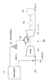
- FIG. 11 shows a basic configuration of this gas turbine.
- the gas turbine 100 includes a compressor 102, a combustor 103, and a turbine 101.
- the combustor 103 is supplied with air compressed by the compressor 102 and fuel gas whose flow rate is adjusted by a fuel flow rate adjustment valve 105 whose opening degree is adjusted according to the load.
- the combustor 103 the combusted high-temperature combustion gas is supplied to the turbine 101 and expands to drive the turbine 101.
- This driving force is transmitted to the generator 150 to generate power, and is transmitted to the compressor 102 to drive the compressor.
- the rotating shafts of the gas turbine 100, the generator 150, and the steam turbine 160 are coupled together.
- an inlet guide vane (InletVGuide Vane: IGV) 104 is provided in front of the first stage blade of the compressor 102.
- the inlet guide vane 104 changes the amount of air flowing between the moving blades of the compressor 102 and flowing into the combustor 103 by manipulating the opening degree of the guide vane at the compressor inlet. This is for controlling the exhaust gas temperature to a target value.
- the intake air is given a circumferential speed by the inlet guide vanes 104 and introduced into the compressor 102. In the compressor 102, energy is given to the introduced air through multistage moving blades and stationary blades, and the pressure rises.
- the inlet guide vanes 104 are configured such that a large number of movable vanes provided in the circumferential direction are movably supported, and an actuator is actuated by a drive signal from the operation control device 110 to move these movable vanes.
- the intake flow rate and combustion temperature are adjusted.
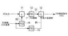
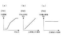
- the operation control device 110 has a configuration as shown in FIG. 12 in order to generate an IGV opening command to the actuator of the inlet guide vane 104. That is, the configuration includes a multiplier 11, a table function unit (FX1) 12, a limiter 13, a correction function unit (FX2) 14, and a limit function unit (FX3) 15. Basically, the IGV opening is set according to a function as shown in FIG. 13A in accordance with the generator output (GT output). Then, the correction function unit (FX2) 14 generates a GT output correction coefficient K2 based on the relationship corresponding to the compressor inlet temperature as shown in FIG. 13B, and the multiplier 11 outputs this correction coefficient K2 to the GT output.
- GT output generator output
- the limit function unit (FX3) 15 generates the IGV maximum opening M1 based on the relationship corresponding to the compressor inlet temperature as shown in FIG. 13C, and the limiter 13 generates the table function unit (FX1) 12. Is limited so that the IGV opening generated in step S1 does not exceed the IGV maximum opening M1.
- Patent Literature 1 and Patent Literature 2 are disclosed as prior arts for performing operation control corresponding to frequency fluctuations in this way.
- Patent Document 1 discloses a technique for switching to control based on recovery of a system frequency that is different from normal control when an abnormality in the system frequency is detected.
- Patent Document 2 discloses a governor-free control method for adjusting the rate of change of the system frequency to be within the limit.
- the gas turbine 100 increases the fuel with respect to the load increase according to the settling rate when the frequency is decreased due to the partial load or against the load increase command, while the combustion temperature (turbine inlet temperature) is increased. Since the temperature control operation is performed from the viewpoint of equipment protection such as equipment damage due to the rise of), there is a concern that a desired load cannot be obtained.
- the Grid Code request response for the shaft output shown in FIG. 14C may not be satisfied.
- the increase in the output (ST output) of the steam turbine 160 is delayed as shown in FIG.
- the present invention has been made in view of such circumstances, and is capable of increasing output without increasing the turbine inlet temperature, regardless of the operation state of the gas turbine, and a gas turbine control device. And it aims at providing the control method of a gas turbine.
- the gas turbine control device, gas turbine, and gas turbine control method of the present invention employ the following means.
- a gas turbine control apparatus supplies compressed air and fuel from a compressor having an inlet guide vane in a front stage to a combustor and rotates the turbine by combustion gas generated in the combustor.
- the IGV advance opening is performed.
- IGV control flag generating means for making the flag effective
- inlet guide blade opening setting means for setting the opening of the inlet guide blade to be opened as compared with the previous opening when the IGV preceding opening flag is effective Prepare.
- the IGV control flag generation means enables the IGV advance opening flag.
- the opening degree of the inlet guide vane is set by the inlet guide vane opening degree setting means so that the opening degree of the inlet guide vane is opened as compared with that.
- the turbine inlet temperature is proportional to the fuel / air ratio (fuel ratio / combustion air ratio)
- fuel / air ratio fuel ratio / combustion air ratio
- turbine inlet temperature decreases.
- turbine output turbine passage flow rate ⁇ turbine heat drop ⁇ efficiency
- the IGV control flag generation means may enable the IGV advance open flag when the system frequency is equal to or lower than a predetermined threshold value or when the output increase of the gas turbine is requested.
- the output can be increased without increasing the turbine inlet temperature regardless of the operating state of the gas turbine.
- the inlet guide vane opening degree setting means is configured such that the rate of change of the inlet guide vane opening degree is set so that the increase in turbine output is faster than the increase in compressor power. Also good.
- the temperature control means for setting the temperature adjustment according to the passenger compartment pressure is provided, and the temperature control means changes the opening degree of the inlet guide vane when the IGV advance open flag is valid.
- the followability of the exhaust gas temperature setting value or the blade path temperature setting value can be accelerated, and the temperature setting can be released in a transient manner, so that the load responsiveness to fluctuations in the system frequency can be improved.
- the temperature control means for setting the temperature adjustment according to the cabin pressure, and the temperature control means has a deviation between the target value based on the temperature adjustment setting and the measured blade path temperature or exhaust gas temperature.
- PI control means for generating a blade path temperature set value or an exhaust gas temperature set value of the turbine by performing proportional integral control based on the IGV, and when the IGV advance open flag is valid, control parameters in the PI control means are It may be set to a preset value.
- the temperature control means for setting the temperature adjustment according to the cabin pressure is provided, and the temperature control means changes the opening degree of the inlet guide blade when the IGV advance open flag is valid.
- a second correction unit that calculates a correction amount according to the rate of change by calculating a rate and corrects the blade path temperature setting value or the exhaust gas temperature setting value of the turbine generated based on the temperature control setting; Good.
- the blade path temperature setting value or the exhaust gas temperature setting value can be directly preceded, the follow-up performance can be accelerated, the temperature setting can be released in a transient manner, and the load response to fluctuations in the system frequency can be increased. Can be improved.
- the IGV control flag generation means may invalidate the IGV preceding opening flag with a certain delay when the IGV preceding opening flag switches from valid to invalid.
- the fuel flow rate may be increased according to the opening degree of the inlet guide vane when the IGV preceding opening flag is validated.
- the fuel flow rate can be increased in accordance with the increase in the air flow rate due to the opening of the inlet guide vanes becoming open, so that an excessive decrease in the turbine inlet temperature can be prevented.
- a gas turbine includes a compressor including an inlet guide vane in a front stage, a combustor that is supplied with compressed air and fuel from the compressor, and generates combustion gas, and the combustor.
- a turbine that is rotated by the generated combustion gas, a generator that is driven by the rotation of the turbine, and the control device described above are provided.
- compressed air and fuel from a compressor having an inlet guide vane in the preceding stage are supplied to the combustor, and the turbine is rotated by the combustion gas generated in the combustor.
- a gas turbine control method for driving a generator to increase an output of the gas turbine, and an IGV control flag valid step for validating an IGV advance open flag, and the IGV advance open flag is valid there is an inlet guide vane opening degree setting step for setting the opening degree of the inlet guide vane to be larger than before.
- FIG. 1 is a configuration diagram of a gas turbine according to a first embodiment of the present invention. It is a block diagram of the IGV control flag production
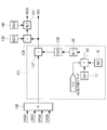
- FIG. 1 is a configuration diagram of a gas turbine 100 according to the first embodiment.
- a gas turbine 100 includes a compressor 102, a combustor 103, and a turbine 101.
- the air compressed by the compressor 102 and the fuel whose flow rate is adjusted by the fuel flow rate adjustment valve 105 are supplied to the combustor 103, where they are mixed and burned to generate high-pressure combustion gas.
- the high-temperature combustion gas is supplied to the turbine 101, and drives the turbine 101 by expanding. This driving force is transmitted to the generator 150 to generate power, and is transmitted to the compressor 102 to drive the compressor 102.
- the fuel flow rate adjustment valve 105 is actuated by a control signal 118 from the fuel control unit 112 of the operation control device 110.
- the fuel flow rate adjusting valve 105 adjusts the load and further the exhaust gas temperature by controlling the fuel flow rate of the fuel gas as described above.
- the rotating shafts of the gas turbine 100, the generator 150, and the steam turbine 160 are coupled together.
- An inlet guide vane (Inlet Guide Vane: IGV) 104 is provided on the front side of the first stage blade of the compressor 102.
- the intake air is given a circumferential speed by the inlet guide vanes 104 and introduced into the compressor 102.
- the inlet guide vanes 104 are configured such that a large number of movable vanes provided in the circumferential direction are rotatably supported, and the inlet guide vanes 104 are controlled by an IGV opening command from the IGV control unit 113 of the operation control device 110. These actuators are actuated to move these movable blades to adjust the intake air flow rate and the combustion temperature.
- a blade path temperature detector 123 that detects the temperature of the gas that has passed through the blades of the final stage is provided at the final stage of the turbine 101. Further, an exhaust gas temperature detector 124 for detecting the temperature of the exhaust gas is provided in the exhaust passage downstream of the position where the blade path temperature detector 123 is disposed. In addition, an intake air condition detector 121 that detects the intake air condition is provided to detect the intake air temperature and the intake air pressure. The pressure in the passenger compartment of the combustor 103 is detected by the passenger compartment pressure sensor 122. Furthermore, a generator output sensor (not shown) is provided to detect the load state of the turbine 101.
- the detection signals detected by the blade path temperature detector 123, the exhaust gas temperature detector 124, the intake air state detector 121, the vehicle interior pressure sensor 122, and the generator output sensor are input to the operation control device 110.
- the operation control device 110 includes a fuel control unit 112 that performs fuel supply control, a temperature control unit 114 that performs blade path temperature control and exhaust gas temperature control, and an IGV control unit 113 that performs opening degree control of the inlet guide vanes 104. And an IGV control flag generation unit 115 that generates an IGV preceding opening flag (IGV preceding opening signal).
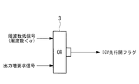
- FIG. 2 is a configuration diagram of the IGV control flag generation unit 115.
- the IGV control flag generation unit 115 validates the IGV preceding open flag when increasing the output of the gas turbine 100. For example, the IGV control flag generation unit 115 receives a low frequency signal when the system frequency is equal to or lower than the predetermined threshold value ⁇ , or when an output increase request signal that requests an increase in the output of the gas turbine 100 is input.
- the IGV preceding open flag is generated as valid by the OR gate 3.
- the gas turbine 100 increases the output in order to increase the system frequency.
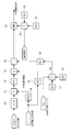
- the IGV control unit 113 is configured as shown in FIG.
- the multiplier 11, the table function unit (FX1) 12, the limiter 13, the correction function unit (FX2) 14, and the limit function unit (FX3) 15 have the same configuration as that of the conventional one (see FIG. 12).
- a configuration in which an addition amount based on the IGV preceding opening flag is added to the conventional IGV opening command and a configuration in which the rate of change of the IGV opening is limited are added. ing.
- the value of the GT output is input to the multiplier 11 via the filter 10.
- the signal generators (SG1) 17 and (SG2) 18 are switched by the signal switcher 19 in accordance with the IGV advance open flag, and the IGV in the normal operation by the adder 16 via the rate limiter 20. It is added to the opening command.
- the opening degree of the inlet guide vane 104 is set so as to be opened as compared to that. For example, when “0” is set in the signal generator (SG1) 17 and a predetermined value is set in the signal generator (SG2) 18, and the IGV advance open flag becomes valid, the IGV opening command during normal operation is set. Is added with a predetermined value of the signal generator (SG2) 18 so that the opening of the inlet guide vane 104 is opened more than usual.
- limits the change rate of IGV opening degree switches signal generator (SG3) 23 and (SG4) 24 with the signal switcher 25 according to a load cutoff flag, and supplies this to the change rate limiter 21
- the change rate limit value of the IGV opening is changed.
- the signal generator (SG3) 23 has a normal rate of change limit value (for example, 400 [% / min])
- the signal generator (SG4) 24 has a rate of change limit value at the time of load interruption ( For example, 3000 [% / min]) is set.
- the operation control device 110 of the gas turbine 100 When the gas turbine 100 is operated at a partial load and the system frequency is equal to or less than the predetermined threshold value ⁇ , or when the gas turbine 100 is operated at a partial load, an increase in the output of the gas turbine 100 is requested.
- the IGV control flag generation unit 115 validates the IGV advance open flag.
- the opening degree of the inlet guide vane 104 is set so as to be opened compared to that so far, and the opening degree of the inlet guide vane 104 is slightly open compared to the normal.
- the turbine inlet temperature is proportional to the fuel-air ratio (fuel amount / combustion air amount ratio)
- the fuel-air ratio that is, the turbine inlet temperature decreases. That is, when the IGV preceding opening flag is validated, the inlet guide vanes 104 are opened more easily than the normal setting, so that the intake air flow rate of the compressor 102 increases from the normal setting.
- the gas turbine 100 can be operated with a lower turbine inlet temperature than usual, so that the turbine output can be increased by increasing the air volume.
- the opening degree of the inlet guide vanes 104 is increased by 10 to 20%, and the air volume is increased by 5% to 10% from the rated flow rate.
- turbine output turbine passage flow rate ⁇ turbine heat drop ⁇ efficiency
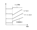
- the inlet guide vanes 104 When the inlet guide vanes 104 are opened, the intake air flow rate of the compressor 102 increases, so that the power of the compressor 102 increases. Therefore, as shown in the example of FIG. 4, when the inlet guide vanes 104 are sharply opened, the power of the compressor 102 increases faster than the increase in turbine output, and as a result, the GT output (generator output) is temporarily increased. May decrease. For this reason, in the rate limiter 20, the rate of change is set so that the increase in turbine output is faster than the increase in power of the compressor 102. Thereby, the temporary reduction of GT output accompanying the increase in the motive power of the compressor 102 by opening the inlet guide blade 104 can be suppressed.
- the operation control device 110 for the gas turbine 100 enables the IGV preceding open flag when the system frequency is equal to or lower than the predetermined threshold value ⁇ or when the output of the gas turbine 100 is requested to increase.
- the opening degree of the inlet guide vane 104 is set so as to be opened as compared to that. Therefore, regardless of the operating state of the gas turbine 100, the output can be increased without increasing the turbine inlet temperature.
- the gas turbine 100 performs opening control of the fuel flow rate adjustment valve 105 by a control signal 118 from a fuel control unit 112 provided in the operation control device 110, and performs load adjustment by fuel flow rate control.
- a fuel control unit 112 provided in the operation control device 110, and performs load adjustment by fuel flow rate control.
- this fuel control unit 112 based on the blade path temperature set value BPCSO in the blade path temperature control, the exhaust gas temperature set value EXCSO in the exhaust gas temperature control, the governor set value GVCSO in the governor control, or the load limit set value LDCSO in the load limit control, Of these, the lowest value is used as the final control signal 118 for the fuel flow control valve 105.
- the blade path temperature (exhaust gas temperature immediately after the final stage of the turbine 101) is measured, and this is compared with a target value based on the temperature control setting, and the blade is controlled by proportional integral (PI) control.
- a pass temperature set value BPCSO is generated.
- the exhaust gas temperature control the exhaust gas temperature (exhaust gas temperature in the exhaust duct downstream from the final stage of the turbine 101) is measured, and this is compared with the target value based on the temperature control setting, and the proportional integral (PI)
- the exhaust gas temperature set value EXCSO is generated by the control.
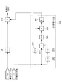
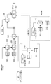
- FIG. 5 is a configuration diagram of a portion that generates the temperature adjustment setting (exhaust gas temperature adjustment setting) EXREF in the temperature control unit 114 of the second embodiment.
- the portion of the temperature control unit 114 that generates the temperature adjustment setting EXREF includes a function unit (FX11) 31, an adder 210, and a preceding signal generation unit 200.
- the function unit (FX11) 31 is set with a function indicating the relationship between the passenger compartment pressure and the temperature control setting during normal operation. That is, the temperature adjustment setting EXREF based on the function unit (FX11) 31 is generated during normal operation in which the opening command value IGV of the inlet guide vane 104 is, for example, 0 [degrees] or more.
- the preceding signal generation unit 200 includes first-order lag filters 202 and 203, a subtractor 204, a function unit (FX16) 205, a function unit (FX15) 201, a multiplier 206, and a rate limiter 207.
- the number of the first-order lag filters 202 and 203 may be one (for example, only 202) or three.
- the subtractor 204 and the first-order lag filters 202 and 203 calculate a change rate, and are not limited to this configuration as long as the change rate is detected.
- the subtracter 204 obtains a deviation between the IGV opening command value and the signal delayed by the first-order lag filters 202 and 203 and the signal not delayed, and this deviation is calculated as the IGV opening command value.
- the rate of change (pseudo-differential value).
- a correction amount (preceding signal) to the temperature adjustment setting EXREF is set in accordance with the change rate (pseudo-differential value) of the IGV opening command value.
- the function unit (FX15) 201 sets the operating range of the preceding signal generation unit 200 only when the opening degree of the inlet guide vane 104 is within a predetermined range.
- the function FX15 has a partial IGV opening degree. A state in which the gas turbine 100 is operating at a partial load by using a function that sets the opening range at the time of loading to “1” and “0” at the time of full opening, and multiplying this by the multiplier 206
- the correction (preceding signal) by the preceding signal generation unit 200 can be made effective only at.
- the rate limiter 207 limits the correction amount to the obtained temperature adjustment setting EXREF, that is, the time change rate of the preceding signal.
- the correction amount via the rate limiter 207 is added by the adder 210, and the temperature adjustment is performed. Generated as setting EXREF.
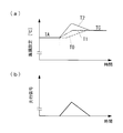
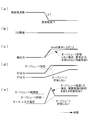
- the temporal transition of the temperature adjustment setting EXREF at this time is as shown by T1 in FIG. 6A, but the actual blade path temperature or exhaust gas temperature has a temperature measurement delay, so T0 in FIG. 6A. As shown in the figure, it changes slowly. Therefore, in the second embodiment, by adding the correction amount (preceding signal) by the preceding signal generation unit 200 as shown in FIG. 6B, the temporal transition of the temperature adjustment setting EXREF is shown in FIG. As shown in T2, the followability of the actual blade path temperature or exhaust gas temperature is made faster.
- the leading signal generation unit 200 calculates the change rate of the opening degree of the inlet guide vane 104 and calculates the correction amount according to the change rate. Since the temperature control setting EXREF is corrected, the followability of the blade path temperature setting value and the exhaust gas temperature setting value can be accelerated, the temperature setting can be released transiently, and the load responsiveness to fluctuations in the system frequency can be improved. it can.
- FIG. 7 is a configuration diagram of the blade path temperature control unit in the temperature control unit 114 according to the third embodiment, and a portion that generates the temperature adjustment setting EXREF is omitted as the configuration according to the second embodiment is used. .
- the configurations of the gas turbine 100 and the IGV control unit 113 according to the third embodiment are the same as those of the first embodiment, and description of each component is omitted.
- the blade path temperature control unit provided in the temperature control unit 114 includes signal generators (SG15) 301, (SG16) 303, (SG17) 308, (SG18) 309, (SG19). 311 and (SG20) 312, signal switchers 310 and 313, adder 302, subtractors 305 and 306, low value selector 304, and PI controller 307.
- a value that becomes a lower value between the value obtained by adding the predetermined value SG15 to the temperature adjustment setting EXREF by the adder 302 and the predetermined value SG16 is selected by the low value selector 304 and is set as the target value BPREF.
- a deviation between the value BPREF and the blade path temperature measurement value BPT from the blade path temperature detector 123 is obtained by the subtractor 305, and proportional integration control based on the deviation is performed by the PI controller 307 to generate the blade path temperature set value BPCSO.
- the upper limit value in the PI controller 307 is a deviation between the deviation by the subtractor 305 and the standby value RCSO.
- the blade path temperature control unit is characterized in that the control parameter in the PI control 307 is set to a preset value when the IGV advance open flag is valid.
- the proportional gain and the time constant are switched and set according to the IGV preceding open flag.
- the proportional gain is generated by switching the signal generators (SG17) 308 and (SG18) 309 with the signal switcher 310 in accordance with the IGV preceding open flag.
- the proportional gain at the normal time is set in the signal generator (SG17) 308, and the proportional gain at the time of IGV pre-opening is set in the signal generator (SG18) 309.
- the time constant is generated by switching the signal generators (SG19) 311 and (SG20) 312 with the signal switcher 313 in accordance with the IGV preceding open flag.
- the time constant at the normal time is set in the signal generator (SG19) 311 and the time constant at the time of IGV pre-opening is set in the signal generator (SG20) 312.
- the proportional gain and the time constant are preferably set to smaller values.
- the system frequency is equal to or lower than the predetermined threshold value ⁇ or when the output of the gas turbine 100 is requested to increase, there is urgency and follow-up.
- the deviation between the target value BPREF based on the temperature adjustment setting EXREF and the measured blade path temperature BPT is calculated.
- proportional integral control is performed by the PI controller 307 to generate the blade path temperature set value BPCSO of the turbine 101.
- the control parameter (proportional gain and time constant) in the PI controller 307 is set to a preset value, so that the movement of the blade path temperature set value BPCSO is accelerated in advance. It is possible to improve load responsiveness to fluctuations in system frequency and load increase.
- FIG. 8 is a configuration diagram of the blade path temperature control unit according to the temperature control unit 114 of the fourth embodiment, and the configuration according to the second embodiment is used for the part that generates the temperature adjustment setting EXREF. Omitted. Note that the configurations of the gas turbine 100 and the IGV control unit 113 according to the fourth embodiment are the same as those of the first embodiment, and description of each component will be omitted.
- the blade path temperature control unit provided in the temperature control unit 114 includes signal generators (SG15) 301 and (SG16) 303, adders 302 and 410, and subtractors 305 and 306. And a low value selector 304, a PI controller 307, and a preceding signal generator 400.
- a value that becomes a lower value between the value obtained by adding the predetermined value SG15 to the temperature adjustment setting EXREF by the adder 302 and the predetermined value SG16 is selected by the low value selector 304 and is set as the target value BPREF.
- a deviation between the value BPREF and the blade path temperature measurement value BPT from the blade path temperature detector 123 is obtained by the subtractor 305, and proportional integration control based on the deviation is performed by the PI controller 307 to generate the blade path temperature set value BPCSO.
- the upper limit value in the PI controller 307 is a deviation between the deviation by the subtractor 305 and the standby value RCSO.
- the blade path temperature control unit in the temperature control unit 114 of the fourth embodiment calculates a change rate of the opening degree of the inlet guide vane 104, calculates a correction amount according to the change rate, and based on the temperature adjustment setting EXREF. It is characterized in that a preceding signal generation unit 400 (second correction means) for correcting the generated blade path temperature set value BPCSO is added.
- the preceding signal generation unit 400 includes first-order lag filters 402 and 403, a subtractor 404, a function unit (FX18) 405, a function unit (FX17) 401, a multiplier 406, and a rate limiter 407.
- One or three primary delay filters may be used.
- the subtractor 204 and the first-order lag filters 202 and 203 calculate a change rate, and are not limited to this configuration as long as the change rate is detected.
- a subtracter 404 obtains a deviation between a signal obtained by delaying the IGV opening command value by the first-order lag filters 402 and 403 and a signal not delayed, and this deviation is obtained as the IGV opening command value.
- rate of change pseudo-differential value
- FX18 function unit
- a correction amount (preceding signal) to the blade path temperature set value BPCSO is set according to the magnitude of the change rate of the IGV opening command value (pseudo differential value).
- the function unit (FX17) 401 sets the operating range of the preceding signal generation unit 400 only when the opening degree of the inlet guide vane 104 is within a predetermined range.
- the IGV opening degree is a partial value.
- a state in which the gas turbine 100 is operating at a partial load by using a function such that the opening range at the time of loading is “1” and when the valve is fully opened is “0”, and this is multiplied by the multiplier 306.
- the correction (preceding signal) by the preceding signal generation unit 400 can be made effective only at.
- the rate limiter 407 limits the correction amount to the blade path temperature set value BPCSO, that is, the time change rate of the preceding signal.
- the correction amount via the rate limiter 407 is added by the adder 410, and the blade path temperature setting value BPCSO is added. It is generated as a temperature set value BPCSO.
- the leading signal generation unit 400 calculates the change rate of the opening degree of the inlet guide vane 104, calculates the correction amount according to the change rate, and the blade path. Since correction is performed by adding a correction amount (preceding signal) directly to the temperature setting value BPCSO, the movement of the blade path temperature setting value BPCSO is directly preceded to further speed up the follow-up and make the temperature setting escape transient. The speed can be increased, and the load responsiveness to fluctuations in system frequency and load increases can be improved.
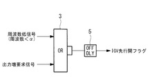
- FIG. 9 is a configuration diagram of the IGV control flag generation unit 115 according to the fifth embodiment.
- the overall configuration of the operation control apparatus 110 for the gas turbine 100 is the same as that of the first to fourth embodiments described above, and the description of each component is omitted.
- the IGV control flag generation unit 115 enables the IGV preceding open flag when the system frequency is equal to or less than the predetermined threshold value ⁇ or when the output of the gas turbine 100 is requested to increase.
- an off delay 5 is added to the output of the OR gate 3.
- This off-delay 5 makes it possible to invalidate the IGV advance open flag with a certain delay when the IGV advance open flag switches from valid to invalid.
- the delay time due to the off-delay 5 is, for example, about the boiler time constant, and is, for example, 5 to 10 minutes.
- the GTCC has a delay in the output (ST output) of the steam turbine 160 when the load increases and the upper limit due to the temperature control operation of the generator 150 output.
- the load responsiveness (followability) was poor at high loads.
- the load following performance is improved by opening the inlet guide vane 104 by a certain amount with the IGV preceding open flag. Since the operation frequently occurs, it is necessary to prevent the frequent occurrence from the viewpoint of performance and component life. Therefore, in the fifth embodiment, by adding the off-delay 5 to the IGV control flag generation unit 115, the IGV advance opening is continued for a certain period even after the frequency constant signal or the output increase request signal is turned off during the load increase. The flag is kept valid. Thus, frequent opening / closing operations of the inlet guide vanes 104 can be prevented from the viewpoint of performance and component life.
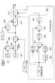
- FIG. 10 is a configuration diagram of the fuel control unit 112 according to the sixth embodiment. Further, the overall configuration of the operation control device 110 of the gas turbine 100 is the same as that of the first to fifth embodiments described above, and the description of each component is omitted.
- the fuel control unit 112 increases the fuel flow rate according to the opening degree of the inlet guide blade 104 when the IGV preceding opening flag is validated.
- the fuel control unit 112 includes a CSO correction unit 131 that corrects the CSO output from the low value selection unit 130.
- the low value selection unit 130 receives the governor set value GVCSO, the load limit set value LDCSO, the blade path temperature set value BPCSO, and the exhaust gas temperature set value EXCSO, and outputs the minimum CSO.
- the CSO correction unit 131 includes a signal generator (SG1) 17, a signal generator (SG2) 18, a signal switch 19, a rate limiter 20, a correction function unit (FX20) 136, and an adder 137. Yes.
- the signal generator (SG1) 17 generates a first signal which is set to 0, for example, the signal generator (SG2) 18 generates a second signal indicating a predetermined value, and the signal switcher 19 is a signal generator.
- (SG1) 17 and signal generator (SG2) 18 are switched according to whether the IGV preceding open flag is valid or invalid.
- the rate limiter 20 limits the rate of time change of the signal from the signal switching unit 19, and the correction function unit (FX20) 136 sets the fuel flow rate (CSO) corresponding to the increase in the air flow rate set by the IGV advance opening flag. A correction value is calculated.
- the adder 137 adds the correction value output from the correction function unit (FX20) 136 to the CSO output from the low value selection unit 130, and outputs the result as the corrected CSO.
- the signal switch 19 selects the first signal of the signal generator (SG1) 17 and the correction value corresponding to the first signal is a low value selection unit. It is added to the CSO output from 130. At this time, since the first signal is set to “0”, when the IGV preceding open flag is invalid, the CSO selected by the low value selection unit 130 is output as it is as the corrected CSO. On the other hand, when the IGV advance open flag is valid, the signal switch 19 selects the second signal of the signal generator (SG2) 18, and the correction value corresponding to the second signal is output from the low value selector 130. Added to CSO.
- the correction value is added to the CSO selected by the low value selection unit 130 and output as the corrected CSO.
- the flow rate of fuel supplied to the combustor 103 increases.
- the standby value RCSO is obtained by adding the value output from the signal generator (SG32) 138 to the CSO output from the adder 137 by the adder 139, and the change rate (output from the signal generator (SG33) 140 ( It is calculated via the rate limiter 141 according to (decrease rate).
- the turbine inlet temperature is excessively lowered by making the opening of the inlet guide vanes 104 more open than usual in order to improve load followability. Is concerned.
- the fuel flow rate can be increased according to the increase in the air flow rate due to the opening degree of the inlet guide vanes 104 becoming open, so that the turbine inlet port An excessive decrease in temperature can be prevented.
Landscapes
- Engineering & Computer Science (AREA)
- Chemical & Material Sciences (AREA)
- Combustion & Propulsion (AREA)
- Mechanical Engineering (AREA)
- General Engineering & Computer Science (AREA)
- Physics & Mathematics (AREA)
- Fluid Mechanics (AREA)
- Power Engineering (AREA)
- Control Of Turbines (AREA)
- Control Of Positive-Displacement Air Blowers (AREA)
- Geometry (AREA)
Priority Applications (4)
| Application Number | Priority Date | Filing Date | Title |
|---|---|---|---|
| US15/105,344 US10161317B2 (en) | 2014-02-05 | 2015-02-04 | Gas-turbine control device, gas turbine, and gas-turbine control method |
| KR1020167017342A KR101819844B1 (ko) | 2014-02-05 | 2015-02-04 | 가스 터빈의 제어 장치, 가스 터빈, 및 가스 터빈의 제어 방법 |
| DE112015000664.8T DE112015000664T5 (de) | 2014-02-05 | 2015-02-04 | Gasturbinen-Steuerungsvorrichtung, Gasturbine, und Gasturbinen-Steuerungsverfahren |
| CN201580003346.XA CN105849392B (zh) | 2014-02-05 | 2015-02-04 | 燃气涡轮的控制装置、燃气涡轮、以及燃气涡轮的控制方法 |
Applications Claiming Priority (2)
| Application Number | Priority Date | Filing Date | Title |
|---|---|---|---|
| JP2014-020529 | 2014-02-05 | ||
| JP2014020529A JP6223847B2 (ja) | 2014-02-05 | 2014-02-05 | ガスタービンの制御装置、ガスタービン、及びガスタービンの制御方法 |
Publications (1)
| Publication Number | Publication Date |
|---|---|
| WO2015119135A1 true WO2015119135A1 (ja) | 2015-08-13 |
Family
ID=53777939
Family Applications (1)
| Application Number | Title | Priority Date | Filing Date |
|---|---|---|---|
| PCT/JP2015/053057 WO2015119135A1 (ja) | 2014-02-05 | 2015-02-04 | ガスタービンの制御装置、ガスタービン、及びガスタービンの制御方法 |
Country Status (6)
Cited By (1)
| Publication number | Priority date | Publication date | Assignee | Title |
|---|---|---|---|---|
| CN112360629A (zh) * | 2020-11-27 | 2021-02-12 | 国网北京市电力公司 | 室外抗御极寒气候的燃气轮机发电机组及其运行方法 |
Families Citing this family (11)
| Publication number | Priority date | Publication date | Assignee | Title |
|---|---|---|---|---|
| JP6257035B2 (ja) * | 2014-03-25 | 2018-01-10 | 三菱日立パワーシステムズ株式会社 | ガスタービンの燃焼制御装置および燃焼制御方法並びにプログラム |
| US10221777B2 (en) * | 2014-03-25 | 2019-03-05 | Mitsubishi Hitachi Power Systems, Ltd. | Gas turbine combustion control device and combustion control method and program therefor |
| JP6335720B2 (ja) * | 2014-08-26 | 2018-05-30 | 三菱日立パワーシステムズ株式会社 | 制御装置、システム及び制御方法 |
| JP6763629B2 (ja) * | 2016-12-15 | 2020-09-30 | 三菱パワー株式会社 | ガスタービン制御装置、ガスタービン制御方法 |
| KR101971337B1 (ko) * | 2017-04-24 | 2019-04-22 | 두산중공업 주식회사 | 가스터빈 시스템 및 제어 방법 |
| KR101898386B1 (ko) * | 2017-04-24 | 2018-09-12 | 두산중공업 주식회사 | 가스터빈 시스템 및 제어 방법 |
| JP6867909B2 (ja) * | 2017-08-02 | 2021-05-12 | アズビル株式会社 | 熱式流量計 |
| JP6934835B2 (ja) * | 2018-04-13 | 2021-09-15 | 三菱パワー株式会社 | ガスタービンの制御装置及びガスタービン並びにガスタービンの制御方法 |
| US11486316B2 (en) | 2018-09-13 | 2022-11-01 | Pratt & Whitney Canada Corp. | Method and system for adjusting a variable geometry mechanism |
| JP7173897B2 (ja) * | 2019-02-28 | 2022-11-16 | 三菱重工業株式会社 | ガスタービンの運転方法およびガスタービン |
| CN110107407B (zh) * | 2019-04-19 | 2020-10-27 | 江苏国信淮安第二燃气发电有限责任公司 | 一种优化燃机igv控制提升燃气-蒸汽联合循环效率的方法 |
Citations (2)
| Publication number | Priority date | Publication date | Assignee | Title |
|---|---|---|---|---|
| JP2009114956A (ja) * | 2007-11-06 | 2009-05-28 | Mitsubishi Heavy Ind Ltd | ガスタービンの運転制御装置および運転制御方法 |
| JP2011111996A (ja) * | 2009-11-27 | 2011-06-09 | Mitsubishi Heavy Ind Ltd | ガスタービンの制御装置及びその方法並びに発電プラント |
Family Cites Families (9)
| Publication number | Priority date | Publication date | Assignee | Title |
|---|---|---|---|---|
| JP3887777B2 (ja) * | 2001-12-10 | 2007-02-28 | 株式会社日立製作所 | ガスタービン発電設備のガバナフリー制御方法及び制御装置 |
| JP2003206749A (ja) | 2002-01-17 | 2003-07-25 | Mitsubishi Heavy Ind Ltd | タービン設備及びその運転方法 |
| JP3684208B2 (ja) | 2002-05-20 | 2005-08-17 | 株式会社東芝 | ガスタービン制御装置 |
| JP4427532B2 (ja) * | 2006-09-21 | 2010-03-10 | 三菱重工業株式会社 | ガスタービンの運転制御装置 |
| JP2008121513A (ja) * | 2006-11-10 | 2008-05-29 | Mitsubishi Heavy Ind Ltd | ガスタービン発電システムおよびそのカロリ異常検知方法 |
| US8028511B2 (en) * | 2007-05-30 | 2011-10-04 | Mitsubishi Heavy Industries, Ltd. | Integrated gasification combined cycle power generation plant |
| JP5868671B2 (ja) * | 2011-11-28 | 2016-02-24 | 三菱日立パワーシステムズ株式会社 | 弁制御装置、ガスタービン、及び弁制御方法 |
| JP2014047728A (ja) * | 2012-08-31 | 2014-03-17 | Mitsubishi Heavy Ind Ltd | ガスタービンの制御装置、ガスタービン、及びガスタービンの制御方法 |
| JP6332747B2 (ja) * | 2014-08-06 | 2018-05-30 | 三菱日立パワーシステムズ株式会社 | 流量比算出装置、これを備えている制御装置、この制御装置を備えているガスタービンプラント、流量比算出方法、及び燃料系統の制御方法 |
-
2014
- 2014-02-05 JP JP2014020529A patent/JP6223847B2/ja active Active
-
2015
- 2015-02-04 WO PCT/JP2015/053057 patent/WO2015119135A1/ja active Application Filing
- 2015-02-04 KR KR1020167017342A patent/KR101819844B1/ko active Active
- 2015-02-04 DE DE112015000664.8T patent/DE112015000664T5/de active Pending
- 2015-02-04 US US15/105,344 patent/US10161317B2/en active Active
- 2015-02-04 CN CN201580003346.XA patent/CN105849392B/zh active Active
Patent Citations (2)
| Publication number | Priority date | Publication date | Assignee | Title |
|---|---|---|---|---|
| JP2009114956A (ja) * | 2007-11-06 | 2009-05-28 | Mitsubishi Heavy Ind Ltd | ガスタービンの運転制御装置および運転制御方法 |
| JP2011111996A (ja) * | 2009-11-27 | 2011-06-09 | Mitsubishi Heavy Ind Ltd | ガスタービンの制御装置及びその方法並びに発電プラント |
Cited By (2)
| Publication number | Priority date | Publication date | Assignee | Title |
|---|---|---|---|---|
| CN112360629A (zh) * | 2020-11-27 | 2021-02-12 | 国网北京市电力公司 | 室外抗御极寒气候的燃气轮机发电机组及其运行方法 |
| CN112360629B (zh) * | 2020-11-27 | 2024-05-28 | 国网北京市电力公司 | 室外抗御极寒气候的燃气轮机发电机组及其运行方法 |
Also Published As
| Publication number | Publication date |
|---|---|
| CN105849392B (zh) | 2018-05-29 |
| DE112015000664T5 (de) | 2016-12-01 |
| KR101819844B1 (ko) | 2018-01-17 |
| US20170002748A1 (en) | 2017-01-05 |
| JP6223847B2 (ja) | 2017-11-01 |
| KR20160091416A (ko) | 2016-08-02 |
| CN105849392A (zh) | 2016-08-10 |
| US10161317B2 (en) | 2018-12-25 |
| JP2015148168A (ja) | 2015-08-20 |
Similar Documents
| Publication | Publication Date | Title |
|---|---|---|
| JP6223847B2 (ja) | ガスタービンの制御装置、ガスタービン、及びガスタービンの制御方法 | |
| JP4838785B2 (ja) | ガスタービンの運転制御装置および運転制御方法 | |
| US7422414B2 (en) | Inlet guide vane control device of gas turbine | |
| JP4831820B2 (ja) | ガスタービン出力学習回路及びこれを備えたガスタービンの燃焼制御装置 | |
| WO2016035416A1 (ja) | 制御装置、システム及び制御方法、並びに動力制御装置、ガスタービン及び動力制御方法 | |
| JP6335720B2 (ja) | 制御装置、システム及び制御方法 | |
| JP2010025069A (ja) | 2軸式ガスタービンシステムの制御装置 | |
| US10196942B2 (en) | Multi-shaft combined cycle plant, and control device and operation method thereof | |
| JP4796015B2 (ja) | ガスタービンの運転制御装置および運転制御方法 | |
| JP6730116B2 (ja) | プラント制御装置、プラント制御方法、および発電プラント | |
| JP4885199B2 (ja) | ガスタービン運転制御装置及び方法 | |
| JP2005520086A (ja) | タービンの運転方法 | |
| JP5694112B2 (ja) | 一軸型複合サイクル発電プラント及びその運転方法 | |
| JP5484871B2 (ja) | ガスタービンの制御装置及びその方法並びに発電プラント | |
| JP2014047728A (ja) | ガスタービンの制御装置、ガスタービン、及びガスタービンの制御方法 | |
| JP5843515B2 (ja) | ガスタービン、ガスタービン制御装置、および発電システム | |
| JP5517870B2 (ja) | ガスタービンの制御装置、ガスタービン、及びガスタービンの制御方法 | |
| JP6267087B2 (ja) | 動力制御装置、ガスタービン及び動力制御方法 | |
| JP2002147253A (ja) | ガスタービン保護装置及び燃料制御装置 | |
| JP5595221B2 (ja) | ガスタービンの制御装置、ガスタービン、及びガスタービンの制御方法 | |
| JP2003254011A (ja) | 多軸型コンバインドサイクル発電プラントの運転方法 | |
| JP2003056309A (ja) | タービン制御装置 |
Legal Events
| Date | Code | Title | Description |
|---|---|---|---|
| 121 | Ep: the epo has been informed by wipo that ep was designated in this application |
Ref document number: 15746536 Country of ref document: EP Kind code of ref document: A1 |
|
| WWE | Wipo information: entry into national phase |
Ref document number: 15105344 Country of ref document: US |
|
| ENP | Entry into the national phase |
Ref document number: 20167017342 Country of ref document: KR Kind code of ref document: A |
|
| WWE | Wipo information: entry into national phase |
Ref document number: 112015000664 Country of ref document: DE |
|
| 122 | Ep: pct application non-entry in european phase |
Ref document number: 15746536 Country of ref document: EP Kind code of ref document: A1 |