WO2015115258A1 - 熱交換器 - Google Patents
熱交換器 Download PDFInfo
- Publication number
- WO2015115258A1 WO2015115258A1 PCT/JP2015/051449 JP2015051449W WO2015115258A1 WO 2015115258 A1 WO2015115258 A1 WO 2015115258A1 JP 2015051449 W JP2015051449 W JP 2015051449W WO 2015115258 A1 WO2015115258 A1 WO 2015115258A1
- Authority
- WO
- WIPO (PCT)
- Prior art keywords
- opening
- heat exchanger
- side wall
- space
- connection hole
- Prior art date
- Legal status (The legal status is an assumption and is not a legal conclusion. Google has not performed a legal analysis and makes no representation as to the accuracy of the status listed.)
- Ceased
Links
Images







Classifications
-
- C—CHEMISTRY; METALLURGY
- C04—CEMENTS; CONCRETE; ARTIFICIAL STONE; CERAMICS; REFRACTORIES
- C04B—LIME, MAGNESIA; SLAG; CEMENTS; COMPOSITIONS THEREOF, e.g. MORTARS, CONCRETE OR LIKE BUILDING MATERIALS; ARTIFICIAL STONE; CERAMICS; REFRACTORIES; TREATMENT OF NATURAL STONE
- C04B38/00—Porous mortars, concrete, artificial stone or ceramic ware; Preparation thereof
- C04B38/0006—Honeycomb structures
-
- F—MECHANICAL ENGINEERING; LIGHTING; HEATING; WEAPONS; BLASTING
- F28—HEAT EXCHANGE IN GENERAL
- F28F—DETAILS OF HEAT-EXCHANGE AND HEAT-TRANSFER APPARATUS, OF GENERAL APPLICATION
- F28F21/00—Constructions of heat-exchange apparatus characterised by the selection of particular materials
- F28F21/04—Constructions of heat-exchange apparatus characterised by the selection of particular materials of ceramic; of concrete; of natural stone
-
- F—MECHANICAL ENGINEERING; LIGHTING; HEATING; WEAPONS; BLASTING
- F28—HEAT EXCHANGE IN GENERAL
- F28F—DETAILS OF HEAT-EXCHANGE AND HEAT-TRANSFER APPARATUS, OF GENERAL APPLICATION
- F28F7/00—Elements not covered by group F28F1/00, F28F3/00 or F28F5/00
- F28F7/02—Blocks traversed by passages for heat-exchange media
-
- C—CHEMISTRY; METALLURGY
- C04—CEMENTS; CONCRETE; ARTIFICIAL STONE; CERAMICS; REFRACTORIES
- C04B—LIME, MAGNESIA; SLAG; CEMENTS; COMPOSITIONS THEREOF, e.g. MORTARS, CONCRETE OR LIKE BUILDING MATERIALS; ARTIFICIAL STONE; CERAMICS; REFRACTORIES; TREATMENT OF NATURAL STONE
- C04B2111/00—Mortars, concrete or artificial stone or mixtures to prepare them, characterised by specific function, property or use
- C04B2111/00439—Physico-chemical properties of the materials not provided for elsewhere in C04B2111/00
- C04B2111/00465—Heat conducting materials
Definitions
- the present invention relates to a heat exchanger made of a ceramic honeycomb structure.
- the honeycomb structure is composed of a large number of flow paths that are partitioned by inner walls. When a fluid passes through the flow path of the honeycomb structure, heat, a substance, and the like can be moved through the inner wall, so that it is widely used as a heat exchanger.
- Patent Document 1 is a high-temperature heat exchanger including an element made of a porous silicon carbide sintered body that exchanges heat between a fluid flowing through the inside and a fluid existing outside.
- a high temperature heat exchanger is described in which the element is a honeycomb structure having a plurality of cells extending in the longitudinal direction. It is described that a heat exchanger using such a honeycomb structure is excellent in strength and can efficiently exchange heat between fluids having different temperatures.
- the ceramic is used in the honeycomb structure because the atoms constituting the material are strongly bonded by a covalent bond and have high strength, heat resistance, and corrosion resistance. On the other hand, the ceramic material becomes a hard and brittle material due to such a feature of the covalent bond. For this reason, the ceramic honeycomb structure is manufactured by a simple forming method such as extrusion, and has a simple shape in which flow paths are arranged in one direction. Because of this shape, the parts to which the honeycomb structure is applied are designed on the assumption that the flow paths are aligned in one direction, and the degree of freedom in designing a heat exchanger using the honeycomb structure is small.
- the present invention exceeds the application range of such a conventional heat exchanger composed of a ceramic honeycomb structure, and has a honeycomb structure that can provide a new function to the honeycomb structure and handle a new fluid flow.
- An object is to provide a heat exchanger.
- the heat exchanger of the present invention for solving the above-mentioned problems has at least a first end face, a second end face, a first side wall, and a second side wall, and is partitioned by an inner wall from the first end face to the second end face.
- the first side wall Or a connection hole comprising a first opening formed in the second side wall and a second opening formed on a plurality of inner walls facing the first opening and connecting a plurality of flow paths;
- the flow path having the first or second opening has sealing portions on the first end face and the second end face, respectively, and the flow path having the first or second opening is the connection hole.
- the first space is configured by being connected,
- the flow path without the first opening and the second opening constitutes the second space extending from the first end surface to the second end surface, and the first space and the second space are mutually connected by the inner wall. Isolated.
- the connection hole is not formed in the outermost channel among the plurality of channels facing the first side wall or the second side wall.
- the flow path extends from the first end face toward the second end face.
- the side surface of the honeycomb structure has a first side wall and a second side wall, and the second side wall is located opposite to the first side wall.
- the heat exchanger composed of the honeycomb structure of the present invention unlike the conventional honeycomb structure in which the flow path extends in one direction, a fluid flow can be created in a direction crossing the honeycomb structure. Further, in such a honeycomb structure, since the first opening and the second opening are formed inside the first opening, not only the flow path located on the outermost periphery but also the flow path on the inner side. A fluid flow can be created. In addition, since the second opening is formed at a position facing the first opening, the fluid can be moved to the flow path inside the second opening in the shortest distance, and the fluid flows efficiently. A heat exchanger can be provided. Further, the connection hole is not formed in the outermost channel among the plurality of channels facing the first side wall or the second side wall.
- connection hole and the outside of the honeycomb structure separate a flow path that does not have at least one connection hole.
- the heat exchange is further separated by two large walls constituting the side walls and the flow path, and a small inner wall that intersects the two large side walls with the individual flow paths separated. It becomes a vessel structure, ensuring strength against the force from the outside of the heat exchanger, and easily preventing breakage such as cracks.
- the heat exchanger of the present invention is made of ceramic and has heat resistance and corrosion resistance and high strength, it can handle a fluid even in a severe environment such as a high temperature environment or a corrosive environment.
- the first space has the sealing portions on the first end surface and the second end surface, respectively, so that the fluid from the first end surface and the second end surface side is in the first space. Intrusion can be prevented.
- the first space is separated from the second space by the inner wall, the fluid flowing in the first space (first fluid) and the fluid flowing in the second space (second fluid) are in direct contact with each other. Absent. For this reason, functions, such as heat transfer and filtration, can be held in the inner wall.
- the honeycomb structure of the present invention desirably has the following aspect.
- the heat exchanger has a plurality of the connection holes. Since the heat exchanger of the present invention has a plurality of connection holes, a larger amount of fluid can flow in the direction crossing the flow path of the honeycomb structure.
- connection holes are alternately formed in the plurality of flow paths facing the first side wall or the second side wall.
- the connection holes are alternately formed in the plurality of flow paths facing the first side wall or the second side wall, whereby the flow in the direction crossing the flow path of the honeycomb structure is performed. Can be placed in alternating flow paths. For this reason, the area of the inner wall separating the fluid flowing along the flow path (second fluid) and the fluid flowing in the direction crossing the flow path (first fluid) can be increased.
- the number of the plurality of flow paths facing the first side wall or the second side wall is an odd number.
- the first sidewall or the first sidewall When the number of the plurality of channels facing the two side walls is an odd number, the channels can be arranged alternately and efficiently.
- the first space has a plurality of the connection holes. Since the heat exchanger of the present invention has a plurality of connection holes in the first space, the plurality of connection holes can serve as an inlet and an outlet for the fluid flowing in the first space. By providing the inlet and the outlet with a plurality of connection holes in the first space, the fluid flowing through the first space (first fluid) can be used continuously.
- having a plurality of connection holes in the first space has an effect of increasing the amount of heat passing through the inner wall.
- the amount of heat passing through the inner wall that separates the first space and the second space is proportional to the temperature difference between the first space and the second space.
- the said heat exchanger has the said connection hole in the said 1st side wall and the said 2nd side wall, respectively.
- the first fluid that connects the inlet and the outlet flows through the same distance by passing through any flow path by having connection holes in the first and second side walls, respectively. it can. For this reason, since the 1st fluid can be spread over the whole inner wall, the heat exchanger which can perform heat transfer or mass transfer efficiently can be provided.
- the first opening and the second opening are configured in a slit shape, and the length of the long side of the first opening is longer than the length of the long side of the second opening.
- the heat exchanger of the present invention can efficiently supply fluid from the side of the elongated channel by configuring the first opening and the second opening in a slit shape. Furthermore, by making the first opening larger than the second opening, the resistance of the first fluid in the first opening can be reduced while reducing the influence on the strength reduction of the entire heat exchanger, and the pressure can be reduced. Loss can be reduced efficiently.
- the plurality of second openings are longer in order toward the first opening.
- the heat exchanger of the present invention is configured such that the second opening becomes longer in order toward the first opening, thereby reducing the influence on the strength reduction of the honeycomb structure, while reducing the influence on the first opening.
- the resistance of the first fluid can be reduced, and the pressure loss can be reduced more efficiently.
- the first opening and the second opening are configured in a slit shape, and the length of the long side of the first opening and the length of the long sides of the plurality of second openings are Are also equal.
- the first opening and the second opening are formed in a slit shape, and the length of the long side of the first opening and the length of the long sides of the plurality of second openings are By configuring so that both are equal, the volume of the connection hole formed by the first opening and the second opening can be increased. By increasing the volume of the connection hole, the first fluid can be efficiently distributed according to the resistance generated in each flow path connected to the connection hole.
- connection hole is formed by stacking five or more second openings.
- the heat exchanger of this invention can supply a 1st fluid to the 6th flow path counted from the 1st side wall side by stacking the 2nd opening of five layers or more. By adopting such a configuration, the area of the inner wall that separates the first space and the second space can be increased.
- connection holes are stacked with 10 or more second openings.
- the heat exchanger of the present invention can supply the first fluid to the eleventh channel counted from the first side wall by stacking the second openings of five or more layers. With such a configuration, the area of the inner wall separating the first space and the second space can be further increased.
- the ceramic is made of silicon carbide, silicon-impregnated silicon carbide, alumina, cordierite, silicon nitride, aluminum nitride, or zirconia.
- the heat exchanger according to the present invention is made of any one of silicon carbide, silicon-impregnated silicon carbide, alumina, cordierite, silicon nitride, aluminum nitride, or zirconia. Can be provided.
- the conventional ceramic honeycomb structure New functions can be added that are not found in heat exchangers made of body.
- at least one channel is provided between the connection hole and the outside of the honeycomb structure, it is easy to ensure strength and prevent breakage such as cracks.
- FIG. 1A is a cross-sectional view taken along the line A-A ′ of FIG. 1
- FIG. 1A is a cross-sectional view taken along the line A-A ′ of FIG. 1
- FIG. 1A is a cross-sectional view taken along the line A-A ′ of FIG. 1
- FIG. 1B is a cross-sectional view taken along the line A-A ′ of FIG. 1
- FIG. 1A is a cross-sectional view taken along the line A-A ′ of FIG. 1
- FIG. 1B is a cross-sectional view taken along the line A-A ′ of FIG. 1
- FIG. 1A is a cross-sectional view taken along the line A-A ′ of FIG. 1
- FIG. 1A is a cross-sectional view taken along the line A-A ′ of FIG. 1
- FIG. 1A is a cross-sectional view taken along the line A-A ′ of FIG. 1
- FIG. 1A is a cross-sectional
- FIG. 6 is a cross-sectional view of a modification of the heat exchanger of FIG. 5, (a) is a cross-sectional view taken along the line CC ′ of FIG. 5 (a), (b) is a cross-sectional view taken along the line EE ′ of FIG. FIG. 5C is a sectional view taken along the line DD ′ of FIG. 5A and a sectional view taken along the line FF ′ of FIG. (A) is a perspective view of the heat exchanger of Embodiment 2 which concerns on this invention. (B) is a perspective view of the modification of the heat exchanger of Embodiment 2 which concerns on this invention.
- FIGS. 7C and 7C are cross-sectional views of a heat exchanger according to a second embodiment of the present invention, in which FIG. 7A is a cross-sectional view along GG ′ in FIG. 7A and FIG. 7B is a cross-sectional view along II ′ in FIG.
- FIGS. 7C and 7C are a sectional view taken along line HH ′ in FIG. 7A and a sectional view taken along line JJ ′ in FIG.
- It is explanatory drawing which shows an example of the manufacturing method of the connection hole of the heat exchanger which concerns on this invention, and a connection hole is comprised by 1st and 2nd opening of slit shape with the same length.
- connection hole is slit shape, 1st opening is longer than 2nd opening, and 2nd opening is 1st. It becomes longer toward the opening.
- a connection hole is slit shape, 1st opening is longer than 2nd opening, and 2nd opening is 1st. It becomes longer toward the opening.
- a connection hole is slit shape, 1st opening is shorter than 2nd opening, and 2nd opening is 1st.
- FIG. 4 is a cross-sectional photograph (a) of a connection hole of a heat exchanger made of a honeycomb structure of an experimental example according to the present invention and an explanatory diagram (b) thereof. It is explanatory drawing which shows in detail the cutting position and cutting
- the cross section of the honeycomb structure indicates a cross section cut in the depth direction of the connection hole along the flow path.
- FIG. 17 describes in detail the cutting position of FIG. 3, which is a cross-sectional view of FIG. 4 is a sectional view of FIG. 1
- FIG. 6 is a sectional view of FIG. 5
- FIG. 8 is a sectional view of FIG.
- the pattern and size of the honeycomb of the heat exchanger of the present invention are not particularly limited.
- a heat exchanger made of a honeycomb structure having an 8 ⁇ 8 grid-like flow path has been described.
- a hexagonal flow path honeycomb a combination of octagonal and quadrangular flow paths is used.
- honeycombs There are no particular limitations on honeycombs.
- the shape of the heat exchanger of the present invention is not particularly limited. Other cylinders such as hexahedrons and hexagonal cylinders can also be applied. In the case of a cylinder, a region where a group of connection holes are formed in the side surface can be defined as a first side wall, and a region on the opposite side can be defined as a second side wall.
- the heat exchanger of the present invention has at least a first end surface, a second end surface, a first side wall, and a second side wall, and has a plurality of flow paths partitioned by an inner wall and extending from the first end surface to the second end surface.
- a connection hole comprising: a first opening formed on a plurality of inner walls opposed to the first opening; and a second opening connected to a plurality of flow paths.
- the flow path having an opening has a sealing portion on each of the first end face and the second end face, and the flow path having the first or second opening is connected to the first through the connection hole.
- the channel without the said second space from the first end surface extending in a second end face constitutes a first space, the second space are separated from each other by the inner wall.
- the connection hole is not formed in the outermost channel among the plurality of channels facing the first side wall or the second side wall.
- the flow path extends from the first end face toward the second end face.
- the side surface of the honeycomb structure has a first side wall and a second side wall, and the second side wall is located opposite to the first side wall.
- a fluid flow can be created in a direction across the honeycomb structure.
- a heat exchanger has the first opening and the second opening formed inside the first opening, not only the flow path located on the outermost periphery but also the inner flow path.
- a fluid flow can be created.
- the second opening is formed at a position facing the first opening, the fluid can be moved to the flow path inside the second opening in the shortest distance, and the fluid flows efficiently.
- a honeycomb structure that can be provided can be provided. Furthermore, at least one channel is separated from the connection hole and the outside of the honeycomb structure.
- connection hole and the outside world have a single honeycomb structure separated by two large walls constituting the side walls and the flow path and a small inner wall that intersects the two large walls with the individual flow paths therebetween.
- the strength against the force from the outside of the honeycomb structure is ensured, and breakage such as cracks can be easily prevented.
- the heat exchanger of the present invention is made of ceramic and has heat resistance and corrosion resistance and high strength, it can handle a fluid even in a severe environment such as a high temperature environment or a corrosive environment.
- the first space has sealing portions on the first end surface and the second end surface, respectively, so that the fluid enters the first space from the first end surface and the second end surface side. Can be prevented. Furthermore, since the first space is separated from the second space by the inner wall, the fluid flowing in the first space (first fluid) and the fluid flowing in the second space (second fluid) are in direct contact with each other. Absent. For this reason, functions, such as heat transfer and filtration, can be held in the inner wall.
- the heat exchanger of the present invention is not particularly limited, but preferably has a plurality of connection holes. Since the heat exchanger of the present invention has a plurality of connection holes, a larger amount of fluid can flow in the direction crossing the flow path of the honeycomb structure.
- connection holes are alternately formed in the plurality of flow paths facing the first side wall or the second side wall.
- the connection holes are alternately formed in the plurality of flow paths facing the first side wall or the second side wall, whereby the flow in the direction crossing the flow path of the honeycomb structure is performed. Can be placed in alternating flow paths. For this reason, the area of the inner wall separating the fluid flowing along the flow path (second fluid) and the fluid flowing in the direction crossing the flow path (first fluid) can be increased. It is desirable that the number of the plurality of flow paths facing the first side wall or the second side wall is an odd number.
- the first side wall or the second side wall is formed.
- the number of the plurality of flow paths facing each other is an odd number, they can be arranged alternately and efficiently.
- the first space has a plurality of the connection holes. Since the heat exchanger of the present invention has a plurality of connection holes in the first space, the plurality of connection holes can serve as an inlet and an outlet for the fluid flowing in the first space. By providing an inlet and an outlet with a plurality of connection holes in the first space, the fluid (first fluid) flowing through the first space can be continuously supplied.
- having a plurality of connection holes in the first space has an effect of increasing the amount of heat passing through the inner wall.
- the amount of heat passing through the inner wall that separates the first space and the second space is proportional to the temperature difference between the first space and the second space.
- the heat exchanger of the present invention preferably has the connection holes on the first side wall and the second side wall, respectively.
- the first fluid that connects the inlet and the outlet flows through the same distance by passing through any flow path by having connection holes in the first and second side walls, respectively. it can. For this reason, since the first fluid can be spread over the entire inner wall, it is possible to provide a honeycomb structure capable of efficiently performing heat transfer or mass transfer.
- the first opening and the second opening are formed in a slit shape, and the length of the long side of the first opening is the length of the long side of the second opening. Longer than this is preferable.
- the first opening and the second opening are formed in a slit shape, whereby fluid can be efficiently supplied from the side of the elongated channel. Furthermore, by making the first opening larger than the second opening, it is possible to reduce the resistance of the first fluid in the first opening while reducing the influence on the strength reduction of the entire honeycomb structure, Pressure loss can be reduced efficiently.
- the plurality of second openings become longer in order toward the first opening.
- the heat exchanger of the present invention is configured such that the second opening becomes longer in order toward the first opening, thereby reducing the influence on the strength reduction of the honeycomb structure, while reducing the influence on the first opening.
- the resistance of the first fluid can be reduced, and the pressure loss can be reduced more efficiently.
- the first opening and the second opening are configured in a slit shape, and the length of the long side of the first opening and the length of the long sides of the plurality of second openings are It is preferable that all the lengths are equal.
- the first opening and the second opening are formed in a slit shape, and the length of the long side of the first opening and the length of the long sides of the plurality of second openings are By configuring so that both are equal, the volume of the connection hole formed by the first opening and the second opening can be increased. By increasing the volume of the connection hole, the first fluid can be efficiently distributed according to the resistance generated in each flow path connected to the connection hole.
- connection hole of the heat exchanger of the present invention is preferably formed by stacking five or more second openings.
- the heat exchanger of this invention can supply a 1st fluid to the 6th flow path counted from the 1st side wall side by stacking the 2nd opening of five layers or more.
- the area of the inner wall that separates the first space and the second space can be increased.
- the aspect ratio between the diameter or width and depth of the connection hole formed by stacking the second openings of five layers or more is 6 or more if the channel is a square channel, and the channel in the deep position is connected to the connection hole. Can be connected.
- connection hole of the heat exchanger of the present invention preferably has 10 or more layers of second openings stacked.
- the heat exchanger of the present invention can supply the first fluid to the eleventh channel counted from the first side wall by stacking the second openings of five or more layers. With such a configuration, the area of the inner wall separating the first space and the second space can be further increased.
- the aspect ratio of the diameter or width and depth of the connection hole formed by stacking the second openings of 10 layers or more is 11 or more in the case of a square channel, and a channel at a deeper position is connected. Can be connected with holes.
- the ceramic of the heat exchanger of the present invention is preferably made of any one of silicon carbide, silicon-impregnated silicon carbide, alumina, cordierite, silicon nitride, aluminum nitride, or zirconia.
- the heat exchanger according to the present invention is made of any one of silicon carbide, silicon-impregnated silicon carbide, alumina, cordierite, silicon nitride, aluminum nitride, or zirconia, so that it has heat resistance and corrosion resistance and has a high strength honeycomb structure. Can be provided.
- silicon carbide, silicon carbide impregnated with silicon, aluminum nitride, or silicon nitride When used in a heat exchanger, it is desirable to use silicon carbide, silicon carbide impregnated with silicon, aluminum nitride, or silicon nitride. These ceramics have high thermal conductivity and are suitable as heat exchangers.
- the heat exchanger of the present invention can be obtained by forming connection holes in the first side wall or the second side wall of the honeycomb-shaped ceramic. It can be obtained by forming the first and second openings. Connection holes can be formed in the honeycomb-shaped ceramic on the first side wall or the second side wall by laser processing.
- the laser processing machine used for laser processing is not particularly limited.
- a honeycomb-shaped ceramic can be processed by using a widely used high-power laser beam.
- the wavelength and output of the laser beam of the laser processing machine can be appropriately selected according to the honeycomb ceramic. Further, it is possible to perform processing more efficiently by using a laser processing machine combined with a water flow of a water jet that has recently been used.
- the laser processing method combined with the water jet water flow can guide the laser beam into the water jet water stream and guide it to the processing point while totally reflecting it, and the laser beam passes through a thin water stream without diffusing.
- the depth of focus is deep, and it has higher processing performance than a processing machine using only laser light.
- the heat exchanger of the present invention can be obtained by processing without penetrating the bottom of the connection hole by using a laser processing machine combined with a water flow of a high processing performance water jet. Processing while leaving the bottom of the connection hole can be realized by scattering laser light at a predetermined location and dispersing light energy. By inserting the light diffusing medium at a predetermined location, the laser light is weakened below and cannot be processed.
- the light diffusion medium is not particularly limited as long as light can be dispersed.
- a light-transmitting rod having a curved surface such as a glass rod, devitrified glass, glass having bubbles inside, water, and the like can be used. A light-transmitting substance is not heated by laser light, and light is scattered on a curved surface, so that the ability to process laser light can be reduced, and the bottom of the connection hole can be formed without penetrating. Can be processed.
- devitrified glass has a phase-separated interior even if the surface is not curved, so that light is easily scattered, the ability to process laser light can be reduced, and the bottom is formed without penetrating. be able to. Moreover, it can process by leaving the bottom of a connection hole by filling water in a predetermined location. When filled with water, a large amount of bubbles are generated by boiling water heated by mixing and processing with a water jet stream. For this reason, the laser beam is rapidly attenuated in the filled water, and processing can be performed while leaving the bottom of the connection hole.
- the heat exchanger of the present invention can be processed by tilting or scanning the laser beam according to the shape, although there are various modifications of the connection holes.
- connection hole having a desired shape can be formed by appropriately changing the length of the light diffusion medium inserted into each flow path.
- the sealing part of the heat exchanger of the present invention may be formed in any way and is not particularly limited.
- a plug made of the same ceramic material as that constituting the inner wall may be inserted.
- silicon powder may be applied to the plug as an adhesive and then fired. Silicon melts and functions as an adhesive. Further, for example, it can be obtained by injecting and baking a paste in which an inorganic binder, an organic binder, and inorganic particles are mixed.
- alumina sol, silica sol or the like can be used.
- organic binder polyvinyl alcohol, phenol resin or the like can be used.
- silicon carbide, alumina, cordierite, silicon nitride, aluminum nitride, zirconia or the like can be used.
- Embodiment 1 and Embodiment 2 of the present invention will be described.
- the first embodiment has sealing portions on the first end surface and the second end surface of the flow path constituting the first space, and a connection hole is formed on the first side wall to constitute the first space, and the second It is a heat exchanger with which the 1st end surface and 2nd end surface of this space are open
- Embodiment 2 is a heat exchanger of the following form.
- connection holes are alternately formed in addition to the outermost channel, and the bottom of the connection hole reaches the second end surface.
- the connection hole does not penetrate the second end face.
- the first end face and the second end face of the flow path having the first opening and the second opening each have a sealing portion, thereby constituting a first space.
- the flow path without the first opening and the second opening constitutes a second space extending from the first end surface to the second end surface, and the first space and the second space are separated from each other by the inner wall. .
- the first space has connection holes on the first and second side walls. Three independent spaces constitute the first space, and 40 5 ⁇ 8 independent flow paths constitute the second space.
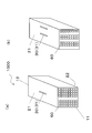
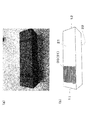
- FIG. 1 is a perspective view of a heat exchanger according to a first embodiment of the present invention.
- FIG. 2 is a perspective view of a modification of the heat exchanger according to the first embodiment of the present invention.
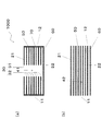
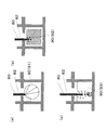
- 3 is a cross-sectional view of the heat exchanger according to the first embodiment of the present invention.
- FIG. 3A is a cross-sectional view taken along the line AA ′ in FIG. 1
- FIG. 3B is a cross-sectional view taken along the line BB ′ in FIG.
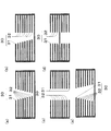
- FIG. 4 is a cross-sectional view of a modification of the connection hole of the heat exchanger according to the first embodiment of the present invention.
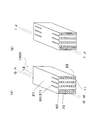
- FIG. 5 is a perspective view of a modification of the heat exchanger according to the first embodiment of the present invention.
- 6 is a cross-sectional view of a modification of the heat exchanger of FIG. 5, where (a) is a cross-sectional view along CC ′ in FIG. 5 (a), and (b) is a cross-sectional view along EE ′ in FIG. 5 (b).
- FIG. 5C is a sectional view taken along the line DD ′ of FIG. 5A and a sectional view taken along the line FF ′ of FIG.
- the heat exchanger of Embodiment 1 includes eight channels 60 that face the first side wall 21 of the honeycomb structure 1000 (heat exchanger) having 8 ⁇ 8 channels.
- three connection holes 30 are provided alternately.
- each connection hole 30 includes a first opening 31 formed in the first side wall 21 and a plurality of second openings 32 formed in the inner wall 50.
- the first opening 31 and the second opening 32 have a slit shape, and the lengths of the first opening 31 and the second opening 32 are the same.
- the cross section of the row adjacent to the row where the connection hole 30 is formed does not have a hole in the inner wall 50.
- connection holes 30 are alternately formed in the plurality of flow paths 60 facing the first side wall 21, and the bottom of the connection holes 30 reaches the second side wall 22. .
- the connection hole 30 does not penetrate the second side wall 22.
- the first end face 11 and the second end face 12 of the flow path having the first opening and the second opening each have a sealing portion 70, thereby forming a first space 41 (FIG. 3A). )reference).
- the flow path without the first opening and the second opening constitutes a second space 42 extending from the first end surface 11 to the second end surface 12 (see FIG. 3B), and the first space and the first space The two spaces are separated from each other by the inner wall.
- the first space has connection holes on the first and second side walls.
- the first space is composed of four independent spaces, and 32 4 ⁇ 8 independent flow paths constitute the second space.
- connection holes 30 are not particularly limited. 2 and 5 are modified examples in which the position and surface shape of the connection hole 30 are different.
- FIG. 2A shows a honeycomb structure 1000 (heat exchanger) having one slit-like connection hole 30, and FIG. 2B shows a part of the channel 60 facing the first side wall 21. A slit-like connection hole 30 is formed. Each connection hole 30 is also formed in a slit shape.
- FIG. 5A shows the four channels 60 alternately arranged in addition to the outermost channel among the eight channels 60 facing the first side wall 21 of the honeycomb structure having 8 ⁇ 8 channels 60.
- a honeycomb structure 1000 (heat exchanger) having a single circular connection hole 30 is shown.
- connection holes 30 is a honeycomb structure 1000 (heat exchanger) including five circular connection holes 30.
- FIG. 5C shows a honeycomb structure 1000 (heat exchanger) having one circular connection hole 30.
- connection hole 30 in the depth direction is not particularly limited.
- FIG. 4 shows a modification of the connection hole 30, is a cross-sectional view of the connection hole 30 in the flow path direction, and shows a cross-section A-A ′ of FIG. 1.
- A shows the connection hole whose cross-sectional shape is V-shaped, the first opening 31 is longer than the second opening 32, and the plurality of second openings 32 are sequentially directed toward the first opening 31. It is configured to be long.
- (B) shows the connection holes aligned so that one side of the first and second openings is vertical.
- the first opening 31 is longer than the second opening 32, and the plurality of second openings 32 are The connection hole is configured to become longer in order toward the first opening 31, and the connection hole has a trapezoidal cross section.
- C shows the connection hole 30 having the same length of the first opening 31 and the second opening 32 and penetrating the first side wall 21 and the second side wall 22.
- D shows the connection hole 30 in which the connection hole 30 is formed from the 1st side wall 21 and the 2nd side wall 22, and each shares the inner wall used as a bottom.
- (E) shows the connection hole 30 having a larger inside, the first opening 31 is shorter than the second opening 32, and the plurality of second openings 32 become shorter toward the first opening 31 in order. It is configured as follows.
- honeycomb pattern and size of the honeycomb structure 1000 are not particularly limited.
- the honeycomb structure 1000 (heat exchanger) having the 8 ⁇ 8 grid-like flow paths 60 has been described.
- a hexagonal flow path honeycomb, octagonal and quadrangular flow paths are used.
- the honeycomb structure (heat exchanger) of the present embodiment can be obtained by forming connection holes in the first side wall or the second side wall of the honeycomb-shaped ceramic.
- the first and second openings can be formed by inserting a light diffusion medium 90 into a flow path 60 facing the second side wall 22 and scanning with laser light 80 as shown in FIG. it can.
- the connection hole 30 having a desired shape can be obtained by appropriately changing the length of insertion of the light diffusion medium as shown in FIG.
- the connection hole 30 having a desired shape may be obtained by scanning the laser beam 80 while appropriately tilting it.
- the honeycomb structure 1000 (heat exchanger) of the present embodiment can be processed by leaving the bottom of the connection hole 30 by inserting the light diffusion medium 90.
- FIGS. 13 and 14 show how the laser light 80 is diffused by the light diffusion medium 90.
- FIGS. 13A, 13B, and 13C show only the laser beam 80
- FIGS. 14A, 14B, and 14C show processing by combining the laser beam 80 and the water flow 82.
- FIGS. As a processing machine in which the laser beam 80 and the water flow 82 are combined, for example, an MCS300 type laser processing machine manufactured by Makino Milling Co. can be used.
- FIGS. 13 (a) and 14 (a) are explanatory views using a glass rod 91 for the light diffusion medium 90, and processing is performed leaving the bottom of the connection hole 30 by diffusion of the laser light 80 by the convex surface of the glass. Can do.
- FIG. 13B and FIG. 14B are explanatory views using a devitrifying glass 91 for the light diffusion medium 90, and the laser light 80 is diffused by irregular reflection inside the glass to leave the bottom of the connection hole 30. can do.
- FIGS. 13 (c) and 14 (c) are explanatory views using water 93 as the light diffusion medium 90.
- the laser light 80 is diffused and connected by the turbulent reflection of bubbles generated by heat and water turbulence due to processing. Processing can be performed leaving the bottom of the hole 30.
- FIG.7 (a) is a perspective view of the heat exchanger of Embodiment 2 which concerns on this invention.
- (A) is a perspective view of the modification of the heat exchanger of Embodiment 2 which concerns on this invention.
- 8A and 8B are cross-sectional views of the heat exchanger according to the second embodiment of the present invention.
- FIG. 8A is a cross-sectional view taken along the line GG ′ of FIG. 7A
- FIG. 8B is a cross-sectional view taken along II of FIG. 'Cross sectional view
- (c) is a HH' sectional view of FIG. 7 (a) and JJ 'sectional view of FIG. 7 (b).
- connection holes 30 are alternately formed in addition to the outermost flow path among the plurality of flow paths 60 facing the first side wall 21. Reaches the second side wall 22. The connection hole 30 does not penetrate the second side wall 22.
- Each of the first end surface 11 and the second end surface 12 of the flow path having the first opening and the second opening has a sealing portion 70, thereby forming a first space 41 (FIG. 8A). ) And (b)).
- the flow path without the first opening and the second opening constitutes a second space 42 extending from the first end surface 11 to the second end surface 12 (see FIG. 8C), and the first space and the first space
- the two spaces are separated from each other by the inner wall.
- the first space has connection holes on the first and second side walls.
- the first space is composed of three independent spaces, and 40 5 ⁇ 8 independent flow paths constitute the second space.
- the first space can create a fluid flow from the first side wall 21 to the second side wall 22 (and vice versa).
- the second space can also create a fluid flow from the first end surface 11 to the second end surface 12 (and vice versa). Since the first space and the second space are separated by the inner wall, they do not mix with each other, and the amount of heat can be moved through the inner wall. This effect can be suitably used as a heat exchanger.
- the honeycomb structure (heat exchanger) of the present embodiment can be obtained by forming connection holes in the first side wall or the second side wall of the honeycomb-shaped ceramic.
- the first and second openings can be processed by inserting a light diffusion medium 90 into a flow path 60 facing the second side wall 22 and scanning with laser light 80. it can.
- the connection hole having a desired shape can be obtained by appropriately changing the length of insertion of the light diffusion medium 90 as shown in FIG.
- a connection hole having a desired shape may be obtained by scanning while appropriately tilting the laser beam 80.
- the honeycomb structure (heat exchanger) of the present embodiment can be processed while leaving the bottom of the connection hole by inserting a light diffusion medium.
- 13 and 14 show how the laser light is diffused by the light diffusion medium 90.
- FIGS. 13A, 13B, and 13C show processing using only laser light
- FIGS. 14A, 14B, and 14C show processing using laser light that also uses a water jet.
- a laser processing machine used in combination with a water jet an MCS300 laser processing machine manufactured by Makino Milling Co. can be used.
- FIGS. 13 (a) and 14 (a) are explanatory views using a glass rod 91 for the light diffusing medium 90, and processing is performed by diffusing the laser light 80 by the convex surface of the glass, leaving the bottom of the connection hole. it can.
- FIG. 13B and FIG. 14B are explanatory diagrams in which a devitrifying glass 92 is used for the light diffusion medium 90, and the laser light 80 is diffused by irregular reflection inside the glass so as to leave the bottom of the connection hole. be able to.
- FIGS. 13 (c) and 14 (c) are explanatory views using water 93 as the light diffusion medium 90.
- the laser light 80 is diffused and connected by the turbulent reflection of bubbles generated by heat and water turbulence due to processing. It can be processed leaving the bottom of the hole.
- FIG. 18 is a perspective view of the heat exchanger according to the third embodiment of the present invention.
- connection holes 30 are alternately formed in the plurality of flow paths 60 facing the first side wall 21, and the bottom of the connection holes 30 is the first. 2 side walls 22 are reached.
- the connection hole 30 is not formed in the outermost channel among the plurality of channels facing the first side wall 21 and the second side wall 22.
- the connection hole 30 is formed on the inner side with at least one layer of the flow path 60 not having the first opening 31 and the second opening 32.
- the plurality of flow paths facing the first side wall 21 and the second side wall 22 are an odd number of seven, of which three are formed with connection holes.
- connection hole 30 including the first opening 31 and the second opening 32 is formed after ensuring one or more channels from the outermost surfaces of the side walls 25 and 26. . Since one or more channels have a honeycomb structure, breakage such as cracks between the side walls 25 and 26 and the first opening 31 and the second opening 32 (connection hole 30) is difficult to occur. The strength of the structure 1000 (heat exchanger) is ensured.
- the first opening 31 (and the second opening 31 and the connection hole 30) closest to the outermost surface of the side wall 25 or 26 is the first opening 31 and the second opening 31 when viewed from the outermost surface of the side wall 25, 26.
- Two or more flow paths 60 that do not have the opening 32 may be formed apart.
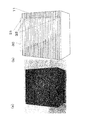
- FIG. 1000 the result of manufacturing a honeycomb structure (heat exchanger) according to the present invention by forming connection holes having a trapezoidal cross section in a honeycomb-shaped ceramic actually made of porous silicon carbide is shown in FIG.
- a honeycomb structure 1000 (heat exchanger) according to the present invention is formed using a honeycomb-shaped ceramic made of silicon carbide of 34 mm ⁇ 34 mm ⁇ 130 mm, having 24 ⁇ 24, a total of 576 square flow paths 60.
- the end surface in the longitudinal direction has a channel opening and is a first end surface 11 and a second end surface 12.
- the four surfaces other than the first end surface 11 and the second end surface 12 are side walls, of which the surface forming the connection hole 30 is the first side wall 21, and the opposite surface is the second side wall 22.
- the inner wall has a thickness of 0.25 mm, and the first and second side walls have a thickness of 0.3 mm.
- the size of the flow path is a square having a side of 1.14 mm.
- connection holes were formed in this honeycomb-shaped ceramic. Twelve connection holes 30 are formed by forming first openings in twelve flow paths alternately among the twenty-four flow paths facing the first side wall, and further forming second openings. did. That is, one of the connection holes at both ends is formed in the outermost flow path among the flow paths facing the first side wall 21, and the other is the outermost flow path among the flow paths facing the first side wall 21. 1 is formed inside. The bottom of the connection hole 30 is the second side wall 22, and the second opening is formed in all the inner walls.
- the distance between the first opening and the second opening and the first end face is 10 mm
- the first opening 31 extends from the first end face 11 to a position of 40 mm
- the second opening 32 in the lowermost layer is the first opening face. It extends from the end face 11 to a position of 25 mm.
- the second opening 32 becomes longer toward the first opening 31 in order, and the connection hole 30 has a trapezoidal cross section.
- the width of the first opening is 0.6 mm.
- connection hole When forming the connection hole, a circular glass rod longer than the flow path is inserted into the flow path facing the second side wall 22, and the circular glass up to a portion other than the trapezoidal basin is inserted into the other flow path. Inserted a stick. Next, it processed using the MCS300 type
- connection hole 30 had a trapezoidal cross section
- the inner wall 50 penetrated all
- the first opening 31 had a length of 30 mm
- the lowermost second opening 32 had a length of 15 mm.
- the method of forming the connection hole 30 in the honeycomb structure 1000 (heat exchanger) is not limited to the laser beam using the water flow 82. If the laser processing machine takes time and has a high output, the water flow is not used together. Can be processed.
- connection holes 30 can be selected as appropriate.
- connection holes force was applied by hand from the side surfaces of the connection holes alternately arranged.
- the side wall on the connection hole side formed in the outermost channel among the channels facing the first side wall 21 is easily cracked, but the outermost channel among the channels facing the other first side wall 21
- the connection hole formed inside one of the channels was not cracked. From these results, it is confirmed that the honeycomb structure in which the connection hole is not formed in the outermost channel among the plurality of channels facing the first side wall or the second side wall has high strength. It was done.
- the heat exchanger of the present invention can be used as a heat exchanger for an internal combustion engine, a combustion furnace, or the like.
Landscapes
- Engineering & Computer Science (AREA)
- Chemical & Material Sciences (AREA)
- Ceramic Engineering (AREA)
- Physics & Mathematics (AREA)
- Thermal Sciences (AREA)
- Mechanical Engineering (AREA)
- General Engineering & Computer Science (AREA)
- Materials Engineering (AREA)
- Structural Engineering (AREA)
- Organic Chemistry (AREA)
- Heat-Exchange Devices With Radiators And Conduit Assemblies (AREA)
- Porous Artificial Stone Or Porous Ceramic Products (AREA)
Abstract
少なくとも第1端面と第2端面と第1側壁と第2側壁とを有し、内壁によって仕切られ第1端面から第2端面に延びる複数の流路を有するセラミック製のハニカム構造体からなり、当該ハニカム構造体の内部に有する第1の空間と第2の空間との間で熱交換をする熱交換器において、第1側壁または第2側壁に形成された第1の開口と、第1の開口に対向する複数の内壁に形成され複数の流路を接続する第2の開口と、からなる接続孔を有し、 第1または第2の開口を有する流路は第1端面および第2端面にそれぞれ封止部を有し、第1または第2の開口を有する流路は接続孔で接続されることにより第1の空間を構成するとともに第1の開口および第2の開口のない流路は、第1端面から第2端面に延びる第2の空間を構成し、第1の空間と、第2の空間は内壁で互いに隔離されている。接続孔は、第1側壁または第2側壁が面する複数の流路のうち、最も外側の流路には形成されていない。
Description
本発明は、セラミック製のハニカム構造体からなる熱交換器に関する。
ハニカム構造体は、内部が内壁によって仕切られた多数の流路で構成されている。ハニカム構造体の流路を流体が通過する際に、内壁を介して熱、物質などを移動させることができるので、熱交換器として広く利用されている。
中でもセラミック製のハニカム構造体は、耐熱性、化学的安定性に優れるので、高い温度、腐食性環境下で使用される熱交換器に用いられている。
特許文献1には、内側を貫流する流体と外側に存在する流体との間で熱量の交換を行わせる多孔質炭化珪素焼結体製のエレメントを備えた高温用熱交換器であって、前記エレメントは長手方向に延びた複数のセルを有するハニカム構造体であることを特徴とした高温用熱交換器が記載されている。このようなハニカム構造体を用いた熱交換器によれば強度に優れると共に、温度の異なる流体間での熱量の交換を効率良く行わせることができることが記載されている。
特許文献1には、内側を貫流する流体と外側に存在する流体との間で熱量の交換を行わせる多孔質炭化珪素焼結体製のエレメントを備えた高温用熱交換器であって、前記エレメントは長手方向に延びた複数のセルを有するハニカム構造体であることを特徴とした高温用熱交換器が記載されている。このようなハニカム構造体を用いた熱交換器によれば強度に優れると共に、温度の異なる流体間での熱量の交換を効率良く行わせることができることが記載されている。
セラミックがハニカム構造体に用いられるのは、材料を構成する原子が共有結合で強く結合し、高強度、耐熱性、耐腐食性を有しているからである。一方、このような共有結合の特長によって、セラミック材料は、硬く、脆い材料となる。
このため、セラミック製のハニカム構造体は、押出成形など単純な成形方法によって製造され、一方向に流路が並んだ単純な形状である。このような形状であるため、ハニカム構造体を適用する部品は一方向に並んだ流路を前提に設計され、ハニカム構造体を用いた熱交換器の設計の自由度は小さい。
このため、セラミック製のハニカム構造体は、押出成形など単純な成形方法によって製造され、一方向に流路が並んだ単純な形状である。このような形状であるため、ハニカム構造体を適用する部品は一方向に並んだ流路を前提に設計され、ハニカム構造体を用いた熱交換器の設計の自由度は小さい。
本発明では、このような従来のセラミック製のハニカム構造体からなる熱交換器の適用範囲を超え、ハニカム構造体に新しい機能を付与し、新しい流体の流れを扱いことのできるハニカム構造体からなる熱交換器を提供することを目的とする。
前記課題を解決するための本発明の熱交換器は、少なくとも第1端面と第2端面と第1側壁と第2側壁とを有し、内壁によって仕切られ前記第1端面から前記第2端面に延びる複数の流路を有するセラミック製のハニカム構造体からなり、当該ハニカム構造体の内部に有する第1の空間と第2の空間との間で熱交換をする熱交換器において、前記第1側壁または前記第2側壁に形成された第1の開口と、前記第1の開口に対向する複数の内壁に形成され複数の流路を接続する第2の開口と、からなる接続孔を有し、前記第1または第2の開口を有する前記流路は前記第1端面および前記第2端面にそれぞれ封止部を有し、前記第1または第2の開口を有する前記流路は前記接続孔で接続されることにより前記第1の空間を構成するとともに、第1の開口および第2の開口のない前記流路は、第1端面から第2端面に延びる前記第2の空間を構成し、前記第1の空間と、前記第2の空間は前記内壁で互いに隔離されている。
ここで、前記接続孔は、前記第1側壁または前記第2側壁が面する複数の前記流路のうち、最も外側の流路には形成されていない。
ここで、前記接続孔は、前記第1側壁または前記第2側壁が面する複数の前記流路のうち、最も外側の流路には形成されていない。
本発明の熱交換器は、第1端面から第2端面に向かって流路が延びている。また、ハニカム構造体の側面は、第1側壁と第2側壁を有し、第2側壁は、第1側壁の反対に位置する。
本発明のハニカム構造体からなる熱交換器によれば、従来の一方向に流路の延びたハニカム構造体とは異なり、ハニカム構造体を横切る方向に流体の流れをつくることができる。また、このようなハニカム構造体は、第1の開口および第1の開口の内側に第2の開口が形成されているので、最外周に位置する流路のみならず、内側の流路にも流体の流れをつくることができる。また、第2の開口は第1の開口に対向する位置に形成されているので、第2の開口の内側の流路との流体の移動を最短距離で行うことができ、効率良く流体が流れることができる熱交換器を提供することができる。
また、接続孔は、第1側壁または第2側壁が面する複数の流路のうち、最も外側の流路には形成されていない。したがって、接続孔とハニカム構造体の外界とは少なくとも一層の接続孔を有していない流路を隔てていることとなる。つまり、接続孔と外界との間は、側壁および流路を構成する2枚の大きな壁と、個々の流路を隔て、2枚の大きな側壁と交差する小さな内壁で隔てられた一層の熱交換器構造となり、熱交換器の外側からの力に対し強度を確保し、ひび割れ等の破損を防止し易くなる。
また、接続孔は、第1側壁または第2側壁が面する複数の流路のうち、最も外側の流路には形成されていない。したがって、接続孔とハニカム構造体の外界とは少なくとも一層の接続孔を有していない流路を隔てていることとなる。つまり、接続孔と外界との間は、側壁および流路を構成する2枚の大きな壁と、個々の流路を隔て、2枚の大きな側壁と交差する小さな内壁で隔てられた一層の熱交換器構造となり、熱交換器の外側からの力に対し強度を確保し、ひび割れ等の破損を防止し易くなる。
また、本発明の熱交換器は、セラミックからなるので、耐熱性、耐蝕性を備え、高強度であるので、高温環境下あるいは腐食性環境下など過酷な環境下でも流体を扱うことができる。
さらに、本発明の熱交換器は、第1の空間が、第1端面および第2端面にそれぞれ封止部を有することによって、第1の空間に第1端面および第2端面側からの流体の侵入を防止することができる。さらに第1の空間は、第2の空間と内壁によって隔てられるため、第1の空間を流れる流体(第1の流体)と第2の空間を流れる流体(第2の流体)とが直接接することない。このため、内壁に伝熱、濾過などの機能を保有させることができる。
さらに、本発明の熱交換器は、第1の空間が、第1端面および第2端面にそれぞれ封止部を有することによって、第1の空間に第1端面および第2端面側からの流体の侵入を防止することができる。さらに第1の空間は、第2の空間と内壁によって隔てられるため、第1の空間を流れる流体(第1の流体)と第2の空間を流れる流体(第2の流体)とが直接接することない。このため、内壁に伝熱、濾過などの機能を保有させることができる。
さらに、本発明のハニカム構造体は、以下の態様であることが望ましい。
(1)前記熱交換器は、前記接続孔を複数有する。
本発明の熱交換器は、接続孔を複数有することによって、より多くの流体をハニカム構造体の流路を横切る方向に流体を流すことができる。
(1)前記熱交換器は、前記接続孔を複数有する。
本発明の熱交換器は、接続孔を複数有することによって、より多くの流体をハニカム構造体の流路を横切る方向に流体を流すことができる。
(2)前記接続孔は、前記第1側壁または前記第2側壁が面する複数の前記流路に交互に形成されている。
本発明の熱交換器は、接続孔が前記第1側壁または前記第2側壁が面する複数の前記流路に交互に形成されていることにより、ハニカム構造体の流路を横切る方向への流れを交互の流路に配置することができる。このため、流路に沿って流れる流体(第2の流体)と、流路を横切る方向に流れる流体(第1の流体)を隔てる内壁の面積を大きくとることができる。
本発明の熱交換器は、接続孔が前記第1側壁または前記第2側壁が面する複数の前記流路に交互に形成されていることにより、ハニカム構造体の流路を横切る方向への流れを交互の流路に配置することができる。このため、流路に沿って流れる流体(第2の流体)と、流路を横切る方向に流れる流体(第1の流体)を隔てる内壁の面積を大きくとることができる。
(3)前記第1側壁または前記第2側壁が面する複数の前記流路の数は奇数である。
接続孔が前記第1側壁または前記第2側壁が面する複数の前記流路のうち最も外側の流路には形成されることなく、交互に形成するためには、前記第1側壁または前記第2側壁が面する複数の流路の数が奇数であると、効率良く交互に配置することができる。
接続孔が前記第1側壁または前記第2側壁が面する複数の前記流路のうち最も外側の流路には形成されることなく、交互に形成するためには、前記第1側壁または前記第2側壁が面する複数の流路の数が奇数であると、効率良く交互に配置することができる。
(4)前記第1の空間は、複数の前記接続孔を有する。
本発明の熱交換器は、第1の空間に複数の接続孔を有することにより、複数の接続孔が、第1の空間を流れる流体の入口と出口となることができる。第1の空間に複数の接続孔により入口と出口を設けることによって、第1の空間を流れる流体(第1の流体)を連続的に使用することができる。
本発明の熱交換器は、第1の空間に複数の接続孔を有することにより、複数の接続孔が、第1の空間を流れる流体の入口と出口となることができる。第1の空間に複数の接続孔により入口と出口を設けることによって、第1の空間を流れる流体(第1の流体)を連続的に使用することができる。
また、第1の空間に複数の接続孔を有することにより、内壁を通過する熱量を大きくする効果もある。第1の空間と第2の空間を隔てる内壁を通過する熱量は、第1の空間と第2の空間の温度差に比例する。第1の空間を流れる流体に入口から入り出口への流れを形成することにより、常に新しい第1の流体を供給し、内壁に温度差が生させ移動する熱量を大きくすることができる。
(5)前記熱交換器は、前記接続孔を前記第1側壁および前記第2側壁にそれぞれ有することが好ましい。
本発明の熱交換器は、接続孔を第1側壁および第2側壁にそれぞれ有することにより、入口と出口を結ぶ第1の流体の流れる距離が、どの流路を通っても同等にすることができる。このため、内壁全体に第1の流体を行き渡らせることができるので効率良く熱移動または物質移動のできる熱交換器を提供することができる。
本発明の熱交換器は、接続孔を第1側壁および第2側壁にそれぞれ有することにより、入口と出口を結ぶ第1の流体の流れる距離が、どの流路を通っても同等にすることができる。このため、内壁全体に第1の流体を行き渡らせることができるので効率良く熱移動または物質移動のできる熱交換器を提供することができる。
(6)前記第1の開口および前記第2の開口は、スリット状に構成され、前記第1の開口の長辺の長さは、前記第2の開口の長辺の長さよりも長い。
本発明の熱交換器は、第1の開口および第2の開口をスリット状に構成することによって、細長い流路の横から効率良く流体を供給することができる。さらに第1の開口を第2の開口よりも大きくすることによって、熱交換器全体の強度低下への影響を小さくしながら第1の開口における第1の流体の抵抗を小さくすることができ、圧力損失を効率良く低減させることができる。
本発明の熱交換器は、第1の開口および第2の開口をスリット状に構成することによって、細長い流路の横から効率良く流体を供給することができる。さらに第1の開口を第2の開口よりも大きくすることによって、熱交換器全体の強度低下への影響を小さくしながら第1の開口における第1の流体の抵抗を小さくすることができ、圧力損失を効率良く低減させることができる。
(7)複数の前記第2の開口は、第1の開口に向かって順に長くなっている。
本発明の熱交換器は、第2の開口は、第1の開口に向かって順に長くなるように構成することによって、ハニカム構造体の強度低下への影響を小さくしながら、第1の開口における第1の流体の抵抗を小さくすることができ、圧力損失をさらに効率良く低減させることができる。
本発明の熱交換器は、第2の開口は、第1の開口に向かって順に長くなるように構成することによって、ハニカム構造体の強度低下への影響を小さくしながら、第1の開口における第1の流体の抵抗を小さくすることができ、圧力損失をさらに効率良く低減させることができる。
(8)前記第1の開口および第2の開口は、スリット状に構成され、前記第1の開口の長辺の長さおよび、複数の前記第2の開口の長辺の長さは、いずれも等しい。
本発明の熱交換器は、第1の開口および第2の開口が、スリット状に形成され、第1の開口の長辺の長さおよび、複数の第2の開口の長辺の長さが、いずれも等しくなるように構成することにより、第1の開口および第2の開口で形成される接続孔の容積を大きくすることができる。接続孔の容積を大きくすることによって、接続孔につながるそれぞれの流路で発生する抵抗に応じて効率良く第1の流体を分配することができる。
本発明の熱交換器は、第1の開口および第2の開口が、スリット状に形成され、第1の開口の長辺の長さおよび、複数の第2の開口の長辺の長さが、いずれも等しくなるように構成することにより、第1の開口および第2の開口で形成される接続孔の容積を大きくすることができる。接続孔の容積を大きくすることによって、接続孔につながるそれぞれの流路で発生する抵抗に応じて効率良く第1の流体を分配することができる。
(9)前記接続孔は5層以上の第2の開口が積み重なっている。
本発明の熱交換器は、5層以上の第2の開口を積み重ねることによって第1の側壁側から数えて6個目の流路に第1の流体を供給することができる。このような構成にすることによって、第1の空間と第2の空間を隔てる内壁の面積を大きくすることができる。
本発明の熱交換器は、5層以上の第2の開口を積み重ねることによって第1の側壁側から数えて6個目の流路に第1の流体を供給することができる。このような構成にすることによって、第1の空間と第2の空間を隔てる内壁の面積を大きくすることができる。
(10)前記接続孔は、10層以上の第2の開口が積み重なっている。
本発明の熱交換器は、5層以上の第2の開口を積み重ねることによって第1の側壁側から数えて11個目の流路に第1の流体を供給することができる。このような構成にすることによって、第1の空間と第2の空間を隔てる内壁の面積をさらに大きくすることができる。
本発明の熱交換器は、5層以上の第2の開口を積み重ねることによって第1の側壁側から数えて11個目の流路に第1の流体を供給することができる。このような構成にすることによって、第1の空間と第2の空間を隔てる内壁の面積をさらに大きくすることができる。
(11)前記セラミックは、炭化珪素、シリコン含浸した炭化珪素、アルミナ、コージェライト、窒化珪素、窒化アルミニウムまたはジルコニアのいずれかよりなる。
本発明の熱交換器は、炭化珪素、シリコン含浸した炭化珪素、アルミナ、コージェライト、窒化珪素、窒化アルミニウムまたはジルコニアのいずれかよりなることにより、耐熱性、耐食性を備え、高強度な熱交換器を提供することができる。
本発明の熱交換器は、炭化珪素、シリコン含浸した炭化珪素、アルミナ、コージェライト、窒化珪素、窒化アルミニウムまたはジルコニアのいずれかよりなることにより、耐熱性、耐食性を備え、高強度な熱交換器を提供することができる。
本発明によれば、熱交換器を構成するハニカム構造体の内壁によって形成される流路のみならず、流路を横切る方向に流体の流れを引き出すことができるので、従来のセラミック製のハニカム構造体からなる熱交換器にない新しい機能を付与することができる。また、接続孔とハニカム構造体の外界との間に少なくとも一層の流路を隔てているため、強度を確保し、ひび割れ等の破損を防止し易くなる。
本明細書において、ハニカム構造体の断面は、流路に沿って接続孔の深さ方向に切断された断面を示す。例えば、図17に図1の断面図である図3の切断位置が詳しく記載されている。図1の断面図である図4、図5の断面図である図6、図7の断面図である図8も同様に断面図が作成されている。
本発明の熱交換器のハニカムのパターン、大きさは特に限定されない。本実施形態では、8×8の格子状の流路を有するハニカム構造体よりなる熱交換器について説明したが、例えば6角形状の流路のハニカム、8角形と4角形の流路の組合せのハニカムなど特に限定されない。
本発明の熱交換器のハニカムのパターン、大きさは特に限定されない。本実施形態では、8×8の格子状の流路を有するハニカム構造体よりなる熱交換器について説明したが、例えば6角形状の流路のハニカム、8角形と4角形の流路の組合せのハニカムなど特に限定されない。
本発明の熱交換器の形状は、特に限定されない。6面体、6角柱などの角柱の他円柱なども適用できる。円柱の場合、側面のうち、一群の接続孔の形成されている領域を第1側壁、その反対側の領域を第2側壁と定義できる。
本発明の熱交換器は、少なくとも第1端面と第2端面と第1側壁と第2側壁とを有し、内壁によって仕切られ前記第1端面から前記第2端面に延びる複数の流路を有するセラミック製のハニカム構造体からなり、当該ハニカム構造体の内部に有する第1の空間と第2の空間との間で熱交換をする熱交換器において、前記第1側壁または前記第2側壁に形成された第1の開口と、前記第1の開口に対向する複数の内壁に形成され複数の流路を接続する第2の開口と、からなる接続孔を有し、前記第1または第2の開口を有する前記流路は前記第1端面および前記第2端面にそれぞれ封止部を有し、前記第1または第2の開口を有する前記流路は前記接続孔で接続されることにより前記第1の空間を構成するとともに、第1の開口および第2の開口のない前記流路は、第1端面から第2端面に延びる前記第2の空間を構成し、前記第1の空間と、前記第2の空間は前記内壁で互いに隔離されている。
ここで、前記接続孔は、前記第1側壁または前記第2側壁が面する複数の前記流路のうち、最も外側の流路には形成されていない。
ここで、前記接続孔は、前記第1側壁または前記第2側壁が面する複数の前記流路のうち、最も外側の流路には形成されていない。
本発明の熱交換器のハニカム構造体は、第1端面から第2端面に向かって流路が延びている。また、ハニカム構造体の側面は、第1側壁と第2側壁を有し、第2側壁は、第1側壁の反対に位置する。
本発明の熱交換器によれば、従来の一方向に流路の延びたハニカム構造体とは異なり、ハニカム構造体を横切る方向に流体の流れをつくることができる。また、このような熱交換器は、第1の開口および第1の開口の内側に第2の開口が形成されているので、最外周に位置する流路のみならず、内側の流路にも流体の流れをつくることができる。また、第2の開口は第1の開口に対向する位置に形成されているので、第2の開口の内側の流路との流体の移動を最短距離で行うことができ、効率良く流体が流れることができるハニカム構造体を提供することができる。
さらに、接続孔とハニカム構造体の外界とは少なくとも一層の流路を隔てていることとなる。つまり、接続孔と外界との間は、側壁および流路を構成する2枚の大きな壁と、個々の流路を隔て2枚の大きな壁と交差する小さな内壁で隔てられた一層のハニカム構造となり、ハニカム構造体の外側からの力に対し強度を確保し、ひび割れ等の破損を防止し易くなる。
さらに、接続孔とハニカム構造体の外界とは少なくとも一層の流路を隔てていることとなる。つまり、接続孔と外界との間は、側壁および流路を構成する2枚の大きな壁と、個々の流路を隔て2枚の大きな壁と交差する小さな内壁で隔てられた一層のハニカム構造となり、ハニカム構造体の外側からの力に対し強度を確保し、ひび割れ等の破損を防止し易くなる。
さらに本発明の熱交換器は、セラミックからなるので、耐熱性、耐蝕性を備え、高強度であるので、高温環境下あるいは腐食性環境下など過酷な環境下でも流体を扱うことができる。
本発明の熱交換器は、第1の空間が、第1端面および第2端面にそれぞれ封止部を有することによって、第1の空間に第1端面および第2端面側からの流体の侵入を防止することができる。さらに第1の空間は、第2の空間と内壁によって隔てられるため、第1の空間を流れる流体(第1の流体)と第2の空間を流れる流体(第2の流体)とが直接接することない。このため、内壁に伝熱、濾過などの機能を保有させることができる。
本発明の熱交換器は、特に限定されないが、接続孔を複数有することが好ましい。
本発明の熱交換器は、接続孔を複数有することによって、より多くの流体をハニカム構造体の流路を横切る方向に流体を流すことができる。
本発明の熱交換器は、接続孔を複数有することによって、より多くの流体をハニカム構造体の流路を横切る方向に流体を流すことができる。
本発明の熱交換器は、前記接続孔が、前記第1側壁または前記第2側壁が面する複数の前記流路に交互に形成されていることが好ましい。
本発明の熱交換器は、接続孔が前記第1側壁または前記第2側壁が面する複数の前記流路に交互に形成されていることにより、ハニカム構造体の流路を横切る方向への流れを交互の流路に配置することができる。このため、流路に沿って流れる流体(第2の流体)と、流路を横切る方向に流れる流体(第1の流体)を隔てる内壁の面積を大きくとることができる。
前記第1側壁または前記第2側壁が面する複数の前記流路の数は奇数であることが望ましい。接続孔が前記第1側壁または前記第2側壁が面する複数の前記流路に最も外側の流路には形成さることなく、交互に形成するためには、前記第1側壁または前記第2側壁が面する複数の流路の数が奇数であると、効率良く交互に配置することができる。
本発明の熱交換器は、接続孔が前記第1側壁または前記第2側壁が面する複数の前記流路に交互に形成されていることにより、ハニカム構造体の流路を横切る方向への流れを交互の流路に配置することができる。このため、流路に沿って流れる流体(第2の流体)と、流路を横切る方向に流れる流体(第1の流体)を隔てる内壁の面積を大きくとることができる。
前記第1側壁または前記第2側壁が面する複数の前記流路の数は奇数であることが望ましい。接続孔が前記第1側壁または前記第2側壁が面する複数の前記流路に最も外側の流路には形成さることなく、交互に形成するためには、前記第1側壁または前記第2側壁が面する複数の流路の数が奇数であると、効率良く交互に配置することができる。
本発明の熱交換器は、前記第1の空間は、複数の前記接続孔を有することが好ましい。
本発明の熱交換器は、第1の空間に複数の接続孔を有することにより、複数の接続孔が、第1の空間を流れる流体の入口と出口となることができる。第1の空間に複数の接続孔により入口と出口を設けることによって、第1の空間を流れる流体(第1の流体)を連続的に供給することができる。
本発明の熱交換器は、第1の空間に複数の接続孔を有することにより、複数の接続孔が、第1の空間を流れる流体の入口と出口となることができる。第1の空間に複数の接続孔により入口と出口を設けることによって、第1の空間を流れる流体(第1の流体)を連続的に供給することができる。
また、第1の空間に複数の接続孔を有することにより、内壁を通過する熱量を大きくする効果もある。第1の空間と第2の空間を隔てる内壁を通過する熱量は、第1の空間と第2の空間の温度差に比例する。第1の空間を流れる流体に入口から入り出口への流れを形成することにより、常に新しい第1の流体を供給し、内壁に温度差が生させ移動する熱量を大きくすることができる。
本発明の熱交換器は、前記接続孔を前記第1側壁および前記第2側壁にそれぞれ有することが好ましい。
本発明の熱交換器は、接続孔を第1側壁および第2側壁にそれぞれ有することにより、入口と出口を結ぶ第1の流体の流れる距離が、どの流路を通っても同等にすることができる。このため、内壁全体に第1の流体を行き渡らせることができるので効率良く熱移動または物質移動のできるハニカム構造体を提供することができる。
本発明の熱交換器は、接続孔を第1側壁および第2側壁にそれぞれ有することにより、入口と出口を結ぶ第1の流体の流れる距離が、どの流路を通っても同等にすることができる。このため、内壁全体に第1の流体を行き渡らせることができるので効率良く熱移動または物質移動のできるハニカム構造体を提供することができる。
本発明の熱交換器は、前記第1の開口および前記第2の開口が、スリット状に構成され、前記第1の開口の長辺の長さは、前記第2の開口の長辺の長さよりも長いことが好ましい。
本発明のハニカム構造体は、第1の開口および第2の開口をスリット状に構成することによって、細長い流路の横から効率良く流体を供給することができる。さらに第1の開口を第2の開口よりも大きくすることによって、ハニカム構造体全体の強度低下への影響を小さくしながら、第1の開口における第1の流体の抵抗を小さくすることができ、圧力損失を効率良く低減させることができる。
本発明のハニカム構造体は、第1の開口および第2の開口をスリット状に構成することによって、細長い流路の横から効率良く流体を供給することができる。さらに第1の開口を第2の開口よりも大きくすることによって、ハニカム構造体全体の強度低下への影響を小さくしながら、第1の開口における第1の流体の抵抗を小さくすることができ、圧力損失を効率良く低減させることができる。
本発明の熱交換器は、複数の前記第2の開口は、第1の開口に向かって順に長くなっていることが好ましい。
本発明の熱交換器は、第2の開口は、第1の開口に向かって順に長くなるように構成することによって、ハニカム構造体の強度低下への影響を小さくしながら、第1の開口における第1の流体の抵抗を小さくすることができ、圧力損失をさらに効率良く低減させることができる。
本発明の熱交換器は、第2の開口は、第1の開口に向かって順に長くなるように構成することによって、ハニカム構造体の強度低下への影響を小さくしながら、第1の開口における第1の流体の抵抗を小さくすることができ、圧力損失をさらに効率良く低減させることができる。
本発明の熱交換器は、前記第1の開口および第2の開口は、スリット状に構成され、前記第1の開口の長辺の長さおよび、複数の前記第2の開口の長辺の長さは、いずれも等しいことが好ましい。
本発明の熱交換器は、第1の開口および第2の開口が、スリット状に形成され、第1の開口の長辺の長さおよび、複数の第2の開口の長辺の長さが、いずれも等しくなるように構成することにより、第1の開口および第2の開口で形成される接続孔の容積を大きくすることができる。接続孔の容積を大きくすることによって、接続孔につながるそれぞれの流路で発生する抵抗に応じて効率良く第1の流体を分配することができる。
本発明の熱交換器は、第1の開口および第2の開口が、スリット状に形成され、第1の開口の長辺の長さおよび、複数の第2の開口の長辺の長さが、いずれも等しくなるように構成することにより、第1の開口および第2の開口で形成される接続孔の容積を大きくすることができる。接続孔の容積を大きくすることによって、接続孔につながるそれぞれの流路で発生する抵抗に応じて効率良く第1の流体を分配することができる。
本発明の熱交換器の前記接続孔は5層以上の第2の開口が積み重なっているが好ましい。
本発明の熱交換器は、5層以上の第2の開口を積み重ねることによって第1の側壁側から数えて6個目の流路に第1の流体を供給することができる。このような構成にすることによって、第1の空間と第2の空間を隔てる内壁の面積を大きくすることができる。
また、5層以上の第2の開口を積み重ねることにより形成される接続孔の径または幅と深さとのアスペクト比は正方形の流路であれば6以上となり、深い位置にある流路を接続孔でつなぐことができる。
本発明の熱交換器は、5層以上の第2の開口を積み重ねることによって第1の側壁側から数えて6個目の流路に第1の流体を供給することができる。このような構成にすることによって、第1の空間と第2の空間を隔てる内壁の面積を大きくすることができる。
また、5層以上の第2の開口を積み重ねることにより形成される接続孔の径または幅と深さとのアスペクト比は正方形の流路であれば6以上となり、深い位置にある流路を接続孔でつなぐことができる。
本発明の熱交換器の前記接続孔は、10層以上の第2の開口が積み重なっていることが好ましい。
本発明の熱交換器は、5層以上の第2の開口を積み重ねることによって第1の側壁側から数えて11個目の流路に第1の流体を供給することができる。このような構成にすることによって、第1の空間と第2の空間を隔てる内壁の面積をさらに大きくすることができる。
また、10層以上の第2の開口を積み重ねることにより形成される接続孔の径または幅と深さとのアスペクト比は正方形の流路であれば11以上となり、さらに深い位置にある流路を接続孔でつなぐことができる。
本発明の熱交換器は、5層以上の第2の開口を積み重ねることによって第1の側壁側から数えて11個目の流路に第1の流体を供給することができる。このような構成にすることによって、第1の空間と第2の空間を隔てる内壁の面積をさらに大きくすることができる。
また、10層以上の第2の開口を積み重ねることにより形成される接続孔の径または幅と深さとのアスペクト比は正方形の流路であれば11以上となり、さらに深い位置にある流路を接続孔でつなぐことができる。
本発明の熱交換器のセラミックは、炭化珪素、シリコン含浸した炭化珪素、アルミナ、コージェライト、窒化珪素、窒化アルミニウムまたはジルコニアのいずれかよりなることが好ましい。
本発明の熱交換器は、炭化珪素、シリコン含浸した炭化珪素、アルミナ、コージェライト、窒化珪素、窒化アルミニウムまたはジルコニアのいずれかよりなることにより、耐熱性、耐食性を備え、高強度なハニカム構造体を提供することができる。
熱交換器に用いる場合、炭化珪素、シリコンを含浸した炭化珪素、窒化アルミニウム、窒化珪素を用いることが望ましい。これらのセラミックは熱伝導率が高く、熱交換器として好適である。
本発明の熱交換器は、炭化珪素、シリコン含浸した炭化珪素、アルミナ、コージェライト、窒化珪素、窒化アルミニウムまたはジルコニアのいずれかよりなることにより、耐熱性、耐食性を備え、高強度なハニカム構造体を提供することができる。
熱交換器に用いる場合、炭化珪素、シリコンを含浸した炭化珪素、窒化アルミニウム、窒化珪素を用いることが望ましい。これらのセラミックは熱伝導率が高く、熱交換器として好適である。
本発明の熱交換器は、ハニカム状のセラミックの第1側壁または第2側壁に接続孔を形成することにより得ることができる。第1および第2の開口を形成することにより得ることができる。ハニカム状のセラミックに第1側壁または第2側壁にレーザー加工によって接続孔を形成することができる。レーザー加工に用いるレーザー加工機は特に限定されない。広く使用される高出力のレーザー光を用いることによってハニカム状のセラミックを加工することができる。レーザー加工機のレーザー光の波長、出力は、ハニカム状のセラミックに応じて適宜選択することができる。
また、近年利用されるようになったウォータージェットの水流を併用したレーザー加工機を利用するとより効率良く加工することができる。ウォータージェットの水流を併用したレーザー加工法は、ウォータージェットの水流中にレーザー光を導き、全反射させながら加工点に導くことができ、レーザー光が拡散することなく,細い水流中を通過するので、焦点の深度が深く、レーザー光だけの加工機よりも高い加工性能を有している。
また、近年利用されるようになったウォータージェットの水流を併用したレーザー加工機を利用するとより効率良く加工することができる。ウォータージェットの水流を併用したレーザー加工法は、ウォータージェットの水流中にレーザー光を導き、全反射させながら加工点に導くことができ、レーザー光が拡散することなく,細い水流中を通過するので、焦点の深度が深く、レーザー光だけの加工機よりも高い加工性能を有している。
本発明の熱交換器は、高い加工性能のウォータージェットの水流を併用したレーザー加工機を用いて、接続孔の底を貫通させることなく加工することによって得ることができる。
接続孔の底を残して加工するには、レーザー光を所定の箇所で散乱させ、光エネルギーを分散させることにより実現できる。所定の箇所に光拡散媒体を挿入することによりそれより下側ではレーザー光が弱められ、加工することができない。光拡散媒体は光を分散させることができれば特に限定されない。例えば、ガラス棒などの曲面を有する光透過性のある棒、失透ガラス、気泡を内部に有するガラス、水などが利用できる。光透過性のある物質は、レーザー光で加熱されることがない上に、曲面で光が散乱されるので、レーザー光の加工の能力を低下させることができ、貫通させることなく接続孔の底を残して加工することができる。
接続孔の底を残して加工するには、レーザー光を所定の箇所で散乱させ、光エネルギーを分散させることにより実現できる。所定の箇所に光拡散媒体を挿入することによりそれより下側ではレーザー光が弱められ、加工することができない。光拡散媒体は光を分散させることができれば特に限定されない。例えば、ガラス棒などの曲面を有する光透過性のある棒、失透ガラス、気泡を内部に有するガラス、水などが利用できる。光透過性のある物質は、レーザー光で加熱されることがない上に、曲面で光が散乱されるので、レーザー光の加工の能力を低下させることができ、貫通させることなく接続孔の底を残して加工することができる。
また、失透ガラスは、表面が曲面でなくても内部が相分離しているので、光が散乱しやすく、レーザー光の加工の能力を低下させることができ、貫通させることなく底を形成することができる。また、水を所定の箇所に充填することにより接続孔の底を残して加工することができる。水を充填すると、ウォータージェットの水流との混合および加工により加熱された水の沸騰により、大量の気泡を発生させる。このため、充填された水の中でレーザー光が急速に減衰し、接続孔の底を残して加工することができる。なお、水を充填していない場合でも、レーザー光とともに水流によって水が供給されるが、水流に用いられる水は量が少なくレーザー光がセラミックを加工する箇所(加工点)近傍で速やか飛散するので、レーザー光を弱めるほど区間に気泡を形成することができない。
本発明の熱交換器は、様々な接続孔の変形例があるが、形状に応じてレーザー光を、傾斜させたり、走査することにより加工することができる。
また、レーザー光を走査しながら加工する際に、それぞれの流路に挿入する光拡散媒体の長さを適宜変更することにより目的の形状の接続孔を形成することもできる。
本発明の熱交換器の封止部はどのように形成してもよく特に限定されない。例えば、内壁を構成する材料と同じセラミック材料からなる栓を挿入してもよい。例えば、ハニカム構造体が炭化珪素、窒化珪素、シリコン含浸した炭化珪素からなる場合は、シリコンの粉末を接着材として栓に塗布したのち、焼成しても良い。シリコンが溶融し、接着材として機能する。
また、例えば、無機バインダと有機バインダと無機粒子の混合したペーストを注入し、焼成することによって得ることもできる。無機バインダは、アルミナゾル、シリカゾルなどが利用でき、有機バインダは、ポリビニールアルコール、フェノール樹脂などが利用でき、無機粒子は炭化珪素、アルミナ、コージェライト、窒化珪素、窒化アルミニウム、ジルコニアなどが利用できる。
本発明の熱交換器の封止部はどのように形成してもよく特に限定されない。例えば、内壁を構成する材料と同じセラミック材料からなる栓を挿入してもよい。例えば、ハニカム構造体が炭化珪素、窒化珪素、シリコン含浸した炭化珪素からなる場合は、シリコンの粉末を接着材として栓に塗布したのち、焼成しても良い。シリコンが溶融し、接着材として機能する。
また、例えば、無機バインダと有機バインダと無機粒子の混合したペーストを注入し、焼成することによって得ることもできる。無機バインダは、アルミナゾル、シリカゾルなどが利用でき、有機バインダは、ポリビニールアルコール、フェノール樹脂などが利用でき、無機粒子は炭化珪素、アルミナ、コージェライト、窒化珪素、窒化アルミニウム、ジルコニアなどが利用できる。
次に、本発明の実施形態1、実施形態2について、説明する。
実施形態1は、第1の空間を構成する流路の第1端面および第2端面に封止部を有し、第1側壁に接続孔が形成され第1の空間を構成するとともに、第2の空間の第1端面および第2端面が開放している熱交換器である。
実施形態2は、以下形態の熱交換器である。
第1側壁が面する複数の流路のうち最も外側の流路以外に交互に接続孔が形成され、接続孔の底は第2端面まで達している。なお、接続孔は第2端面を貫通していない。第1の開口および第2の開口を有する流路の第1端面および第2端面はそれぞれ封止部を有することにより、第1の空間を構成している。
また第1の開口および第2の開口のない流路は、第1端面から第2端面に延びる第2の空間を構成し、第1の空間と第2の空間は内壁で互いに隔離されている。第1の空間は、第1側壁および第2側壁の側に接続孔を有している。3つの独立した空間が第1の空間を構成し、5×8の独立した流路40本が第2の空間を構成する。
第1側壁が面する複数の流路のうち最も外側の流路以外に交互に接続孔が形成され、接続孔の底は第2端面まで達している。なお、接続孔は第2端面を貫通していない。第1の開口および第2の開口を有する流路の第1端面および第2端面はそれぞれ封止部を有することにより、第1の空間を構成している。
また第1の開口および第2の開口のない流路は、第1端面から第2端面に延びる第2の空間を構成し、第1の空間と第2の空間は内壁で互いに隔離されている。第1の空間は、第1側壁および第2側壁の側に接続孔を有している。3つの独立した空間が第1の空間を構成し、5×8の独立した流路40本が第2の空間を構成する。
<実施形態1>
実施形態1の熱交換器について、図を用いながら説明する。
図1は本発明に係る実施形態1の熱交換器の斜視図。図2は本発明に係る実施形態1の熱交換器の変形例の斜視図。図3は本発明に係る実施形態1の熱交換器の断面図であり、(a)は、図1のA-A’断面図、(b)は図1のB-B’断面図である。図4は本発明に係る実施形態1の熱交換器の接続孔の変形例の断面図である。図1のA-A’の断面図に相当する。図5は本発明に係る実施形態1の熱交換器の変形例の斜視図。図6は図5の熱交換器の変形例の断面図であり、(a)は図5(a)のC-C’断面図、(b)は図5(b)のE-E’断面図、(c)は図5(a)のD-D’断面図および図5(b)のF-F’断面図である。
実施形態1の熱交換器について、図を用いながら説明する。
図1は本発明に係る実施形態1の熱交換器の斜視図。図2は本発明に係る実施形態1の熱交換器の変形例の斜視図。図3は本発明に係る実施形態1の熱交換器の断面図であり、(a)は、図1のA-A’断面図、(b)は図1のB-B’断面図である。図4は本発明に係る実施形態1の熱交換器の接続孔の変形例の断面図である。図1のA-A’の断面図に相当する。図5は本発明に係る実施形態1の熱交換器の変形例の斜視図。図6は図5の熱交換器の変形例の断面図であり、(a)は図5(a)のC-C’断面図、(b)は図5(b)のE-E’断面図、(c)は図5(a)のD-D’断面図および図5(b)のF-F’断面図である。
実施形態1の熱交換器は、図1に示すように、8×8の流路を有するハニカム構造体1000(熱交換器)の第1側壁21に面する8本の流路60のうち、最も外側の流路以外に、交互になるように接続孔30を3本有している。図3(a)に示すように、それぞれの接続孔30は、第1側壁21に形成された第1の開口31および内壁50に形成された複数の第2の開口32により構成される。図3(a)に示されるように第1の開口31および第2の開口32は、スリット状の形状であり、第1の開口31および第2の開口32の長さは同一である。図3(b)に示されるように、接続孔30の形成されている列の隣の列の断面は、内壁50に孔を有していない。
実施形態1のハニカム構造体1000(熱交換器)は第1側壁21が面する複数の流路60に交互に接続孔30が形成され、接続孔30の底は第2側壁22まで達している。なお、接続孔30は第2側壁22を貫通していない。第1の開口および第2の開口を有する流路の第1端面11および第2端面12にはそれぞれ封止部70を有することにより、第1の空間41を構成している(図3(a)参照)。
また第1の開口および第2の開口のない流路は、第1端面11から第2端面12に延びる第2の空間42を構成し(図3(b)参照)、第1の空間と第2の空間は内壁で互いに隔離されている。第1の空間は、第1側壁および第2側壁の側に接続孔を有している。第1の空間は4つの独立した空間で構成され、4×8の独立した流路32本が第2の空間を構成する。
接続孔30の位置、形状、数は特に限定されない。図2および図5は、接続孔30の位置、表面形状の異なる変形例である。図2(a)は1個のスリット状の接続孔30を有するハニカム構造体1000(熱交換器)を示し、図2(b)は、第1側壁21が面する流路60の一部にスリット状の接続孔30が形成されている。いずれの接続孔30もスリット状に形成されている。図5(a)は、8×8の流路60を有するハニカム構造体の第1側壁21に面する8本の流路60のうち、最も外側の流路以外に、交互になるように4個の円形の接続孔30を有するハニカム構造体1000(熱交換器)を示している。図5(b)は、8×8の流路を有するハニカム構造体1000(熱交換器)の第1側壁21に面する8本の流路60のうち、最も外側の流路以外に、交互になるように3つの群の接続孔30を有し、1つの群の接続孔30は、円形の接続孔30が5個で構成されるハニカム構造体1000(熱交換器)である。図5(c)は、1個の円形の接続孔30を有するハニカム構造体1000(熱交換器)を示す。
接続孔30の深さ方向の形状も特に限定されない。図4は、接続孔30の変形例を示し、接続孔30の流路方向の断面図であり、図1のA-A’断面を示す。(a)は、断面形状がV字状である接続孔を示し、第1の開口31が第2の開口32よりも長く、複数の第2の開口32が第1の開口31に向かって順に長くなるように構成されている。(b)は、第1および第2の開口の片側が垂直になるように揃った接続孔を示し、第1の開口31が第2の開口32よりも長く、複数の第2の開口32が第1の開口31に向かって順に長くなるように構成され接続孔の断面が台形である。(c)は、第1の開口31および第2の開口32の長さが同一で第1側壁21および第2側壁22を貫通した接続孔30を示す。(d)は、第1側壁21および第2側壁22から接続孔30が形成され、それぞれ底となる内壁を共有する接続孔30を示す。(e)は、内部の方が大きい接続孔30を示し、第1の開口31が第2の開口32よりも短く、複数の第2の開口32が第1の開口31に向かって順に短くなるように構成されている。
ハニカム構造体1000(熱交換器)のハニカムのパターン、大きさは特に限定されない。本実施形態では、8×8の格子状の流路60を有するハニカム構造体1000(熱交換器)について説明したが、例えば6角形状の流路のハニカム、8角形と4角形の流路の組合せのハニカムなど特に限定されない。
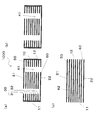
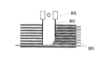
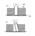
本実施形態のハニカム構造体(熱交換器)は、ハニカム状のセラミックの第1側壁または第2側壁に接続孔を形成することにより得ることができる。第1および第2の開口を形成する方法は,図9に示すように第2側壁22に面する流路60に光拡散媒体90を挿入し、レーザー光80を走査することによって加工することができる。接続孔30の形状によっては、図10のように光拡散媒体の挿入する長さを適宜変えることによって目的の形状の接続孔30を得ることができる。また、図11、図12に示されるようにレーザー光80を適宜傾斜させながら走査することにより、目的の形状の接続孔30を得てもよい。
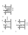
本実施形態のハニカム構造体1000(熱交換器)は、光拡散媒体90を挿入することによって接続孔30の底を残して加工することできる。図13、図14は、光拡散媒体90によってレーザー光80が拡散する様子を示している。図13(a)、(b)、(c)は、レーザー光80のみ、図14(a)、(b)、(c)は、レーザー光80と水流82との複合による加工を示している。レーザー光80と水流82との複合した加工機は、例えば牧野フライス社製MCS300型レーザー加工機を利用することができる。
図13(a)、図14(a)は、光拡散媒体90にガラス棒91を用いた説明図であり、ガラスの凸面によるレーザー光80の拡散によって接続孔30の底を残して加工することができる。
図13(b)、図14(b)は、光拡散媒体90に失透ガラス91を用いた説明図であり、ガラス内部の乱反射によってレーザー光80を拡散させ接続孔30の底を残して加工することができる。
図13(c)、図14(c)は、光拡散媒体90に水93を用いた説明図であり、加工による熱、水の乱流によって発生した気泡の乱反射によってレーザー光80を拡散させ接続孔30の底を残して加工することができる。
図13(b)、図14(b)は、光拡散媒体90に失透ガラス91を用いた説明図であり、ガラス内部の乱反射によってレーザー光80を拡散させ接続孔30の底を残して加工することができる。
図13(c)、図14(c)は、光拡散媒体90に水93を用いた説明図であり、加工による熱、水の乱流によって発生した気泡の乱反射によってレーザー光80を拡散させ接続孔30の底を残して加工することができる。
<実施形態2>
実施形態2の熱交換器について、図を用いながら説明する。
図7(a)は本発明に係る実施形態2の熱交換器の斜視図。(a)は本発明に係る実施形態2の熱交換器の変形例の斜視図。図8は本発明に係る実施形態2の熱交換器の断面図であり、(a)は図7(a)のG-G’断面図、(b)は図7(b)のI-I’断面図、(c)は図7(a)のH-H’断面図、および図7(b)のJ-J’断面図である。
実施形態2の熱交換器について、図を用いながら説明する。
図7(a)は本発明に係る実施形態2の熱交換器の斜視図。(a)は本発明に係る実施形態2の熱交換器の変形例の斜視図。図8は本発明に係る実施形態2の熱交換器の断面図であり、(a)は図7(a)のG-G’断面図、(b)は図7(b)のI-I’断面図、(c)は図7(a)のH-H’断面図、および図7(b)のJ-J’断面図である。
実施形態2のハニカム構造体1000(熱交換器)は第1側壁21が面する複数の流路60のうち、最も外側の流路以外に交互に接続孔30が形成され、接続孔30の底は第2側壁22まで達している。なお、接続孔30は第2側壁22を貫通していない。第1の開口および第2の開口を有する流路の第1端面11および第2端面12にはそれぞれ封止部70を有することにより、第1の空間41を構成している(図8(a)、(b)参照)。
また第1の開口および第2の開口のない流路は、第1端面11から第2端面12に延びる第2の空間42を構成し(図8(c)参照)、第1の空間と第2の空間は内壁で互いに隔離されている。第1の空間は、第1側壁および第2側壁の側に接続孔を有している。第1の空間は3つの独立した空間で構成され、5×8の独立した流路40本が第2の空間を構成する。
第1の空間は、第1側壁21から、第2側壁22への(およびその逆の)流体の流れを作ることができる。また第2の空間は、第1端面11から、第2端面12への(およびその逆の)流体の流れを作ることができる。第1の空間と第2の空間は内壁で隔てられているので、互いに混ざり合うことがなく、内壁を通じて熱量の移動をさせることができる。この効果は熱交換器として好適に利用することができる。
第1の空間は、第1側壁21から、第2側壁22への(およびその逆の)流体の流れを作ることができる。また第2の空間は、第1端面11から、第2端面12への(およびその逆の)流体の流れを作ることができる。第1の空間と第2の空間は内壁で隔てられているので、互いに混ざり合うことがなく、内壁を通じて熱量の移動をさせることができる。この効果は熱交換器として好適に利用することができる。
本実施形態のハニカム構造体(熱交換器)は、ハニカム状のセラミックの第1側壁または第2側壁に接続孔を形成することにより得ることができる。第1および第2の開口を形成する方法は、図9に示すように第2側壁22に面する流路60に光拡散媒体90を挿入し、レーザー光80を走査することによって加工することができる。接続孔の形状によっては、図10のように光拡散媒体90の挿入する長さを適宜変えることによって目的の形状の接続孔を得ることができる。また、図11、図12に示されるようにレーザー光80を適宜傾斜させながら走査することにより、目的の形状の接続孔を得てもよい。
本実施形態のハニカム構造体(熱交換器)は、光拡散媒体を挿入することによって接続孔の底を残して加工することできる。図13、図14は、光拡散媒体90によってレーザー光が拡散する様子を示している。図13(a)、(b)、(c)は、レーザー光のみ、図14(a)、(b)、(c)は、ウォータージェットを併用したレーザー光による加工を示している。ウォータージェットを併用したレーザー加工機は、牧野フライス社製MCS300型レーザー加工機を利用することができる。
図13(a)、図14(a)は、光拡散媒体90にガラス棒91を用いた説明図であり、ガラスの凸面によるレーザー光80の拡散によって接続孔の底を残して加工することができる。
図13(b)、図14(b)は、光拡散媒体90に失透ガラス92を用いた説明図であり、ガラス内部の乱反射によってレーザー光80を拡散させ接続孔の底を残して加工することができる。
図13(c)、図14(c)は、光拡散媒体90に水93を用いた説明図であり、加工による熱、水の乱流によって発生した気泡の乱反射によってレーザー光80を拡散させ接続孔の底を残して加工することができる。
図13(b)、図14(b)は、光拡散媒体90に失透ガラス92を用いた説明図であり、ガラス内部の乱反射によってレーザー光80を拡散させ接続孔の底を残して加工することができる。
図13(c)、図14(c)は、光拡散媒体90に水93を用いた説明図であり、加工による熱、水の乱流によって発生した気泡の乱反射によってレーザー光80を拡散させ接続孔の底を残して加工することができる。
<実施形態3>
実施形態3の熱交換器について、図を用いながら説明する。
図18は本発明に係る実施形態3の熱交換器の斜視図である。
実施形態3の熱交換器について、図を用いながら説明する。
図18は本発明に係る実施形態3の熱交換器の斜視図である。
実施形態3のハニカム構造体1000(熱交換器)は、実施形態2と同様、第1側壁21が面する複数の流路60に交互に接続孔30が形成され、接続孔30の底は第2側壁22まで達している。しかしながら、接続孔30は第1側壁21および第2側壁22が面する複数の流路のうち、最も外側の流路には形成されていない。結果的に、接続孔30が、第1の開口31および第2の開口32を有さない少なくとも一層の流路60を隔てて、内側に形成されている。第1側壁21および第2側壁22が面する複数の流路は奇数の7本であり、そのうち接続孔が形成されているのは3本である。
側壁25、26が接続孔に接していると、側壁25、26が薄板となってしまうため、強度の確保が困難となり、ひび割れ等の破損の発生の可能性が高くなる。一方、図18の構成によれば、第1の開口31および第2の開口32を含む接続孔30が、側壁25、26の最外面から必ず一層以上の流路を確保した上で形成される。一層以上の流路は、ハニカム構造となるため、側壁25、26と第1の開口31および第2の開口32(接続孔30)との間でのひび割れ等の破損が発生し難くなり、ハニカム構造体1000(熱交換器)の強度が確保される。
側壁25または26の最外面から最も近い第1の開口31(および第2の開口31、接続孔30)は、側壁25、26の最外面からから見て、第1の開口31および第2の開口32を有さない二つ以上の流路60を隔てて形成することもできる。
<実験例>
本実験例では、実際に多孔質の炭化珪素からなるハニカム状のセラミックに台形の断面を有する接続孔を形成し、本発明に係るハニカム構造体(熱交換器)を製造した結果について、図15、図16を用いて説明する。
24×24個、計576個の正方形の流路60を有し、34mm×34mm×130mmの炭化珪素からなるハニカム状のセラミックを用いて、本発明に係るハニカム構造体1000(熱交換器)を製作した。なお、長手方向の端面は、流路の開口を有し、第1端面11および第2端面12である。第1端面11および第2端面12以外の4つの面は側壁であり、そのうち接続孔30を形成する面が第1側壁21、その反対側の面が第2側壁22となる。内壁の厚さは0.25mm、第1および第2の側壁の厚さは、0.3mmである。流路の大きさは、一辺が1.14mmの正方形である。
本実験例では、実際に多孔質の炭化珪素からなるハニカム状のセラミックに台形の断面を有する接続孔を形成し、本発明に係るハニカム構造体(熱交換器)を製造した結果について、図15、図16を用いて説明する。
24×24個、計576個の正方形の流路60を有し、34mm×34mm×130mmの炭化珪素からなるハニカム状のセラミックを用いて、本発明に係るハニカム構造体1000(熱交換器)を製作した。なお、長手方向の端面は、流路の開口を有し、第1端面11および第2端面12である。第1端面11および第2端面12以外の4つの面は側壁であり、そのうち接続孔30を形成する面が第1側壁21、その反対側の面が第2側壁22となる。内壁の厚さは0.25mm、第1および第2の側壁の厚さは、0.3mmである。流路の大きさは、一辺が1.14mmの正方形である。
図15に示すように、このハニカム状のセラミックに接続孔を形成した。第1側壁に面する流路24本の内、交互となるよう12本の流路に第1の開口を形成し、さらに第2の開口を形成することにより、12個の接続孔30を形成した。すなわち、両端の接続孔のうち一方は、第1側壁21の面する流路のうち最も外側の流路に形成され、もう一方は第1側壁21の面する流路のうち最も外側の流路の1つ内側に形成される。接続孔30の底は、第2側壁22であり、全ての内壁には第2の開口が形成されている。第1の開口および第2の開口と第1端面との距離は10mm、第1の開口31は第1の端面11から40mmの位置まで延び、最下層の第2の開口32は、第1の端面11から25mmの位置まで延びている。第2の開口32は第1の開口31に向かって順に長くなり、接続孔30の断面は、台形である。また、第1の開口の幅は、0.6mmである。
詳しい加工方法は以下に説明する。接続孔を形成する際、第2側壁22に面する流路には、流路よりも長い円形のガラス棒を挿入し、その他の流路には、前記台形の流域以外の部分まで円形のガラス棒を挿入した。
次に第1側壁に面する流路に沿って牧野フライス社製MCS300型レーザー加工機を用いて加工した。レーザーの波長は532nm、出力80W、水流82のノズル径はφ80μm、走査速度は300mm/minで加工した。
次に第1側壁に面する流路に沿って牧野フライス社製MCS300型レーザー加工機を用いて加工した。レーザーの波長は532nm、出力80W、水流82のノズル径はφ80μm、走査速度は300mm/minで加工した。
このように加工して得られたハニカム構造体1000(熱交換器)を接続孔30に沿って切断し、接続孔30を確認した。図16に示すように接続孔30の断面は台形であり、内壁50は全て貫通し、第1の開口31が長さ30mm、最下層の第2の開口32が長さ15mmであった。
このように水流を用いたレーザー加工機で接続孔を形成できることが確認でできた。ハニカム構造体1000(熱交換器)に接続孔30を形成する方法は水流82を用いたレーザー光に限定されず、時間をかけ、高出力のレーザー加工機であれば、水流を併用することなく加工することができる。
このように水流を用いたレーザー加工機で接続孔を形成できることが確認でできた。ハニカム構造体1000(熱交換器)に接続孔30を形成する方法は水流82を用いたレーザー光に限定されず、時間をかけ、高出力のレーザー加工機であれば、水流を併用することなく加工することができる。
また、接続孔30の大きさ、配置、数は適宜選択することができる。
次に、交互に列となっている接続孔の側面から、手で力を加えた。第一側壁21の面する流路のうち最も外側の流路に形成された接続孔側の側壁は容易にクラックが入ったが、もう一方の第一側壁21の面する流路のうち最も外側の流路の1つ内側に形成された接続孔側はクラックが入らなかった。このような結果から、接続孔が、第1側壁または第2側壁が面する複数の流路のうち、最も外側の流路には形成されていないハニカム構造体は、高い強度を持つことが確認された。
本発明の熱交換器は、内燃機関、燃焼炉などの熱交換器として利用することができる。
11 第1端面
12 第2端面
21 第1側壁
22 第2側壁
30 接続孔
31 第1の開口
32 第2の開口
41 第1の空間
42 第2の空間
50 内壁
60 流路
70 封止部
80 レーザー光
82 水流(ウォータジェット)
85 レーザー源
90 光拡散媒体
91 ガラス棒
92 失透ガラス
93 水
1000 ハニカム構造体(熱交換器)
12 第2端面
21 第1側壁
22 第2側壁
30 接続孔
31 第1の開口
32 第2の開口
41 第1の空間
42 第2の空間
50 内壁
60 流路
70 封止部
80 レーザー光
82 水流(ウォータジェット)
85 レーザー源
90 光拡散媒体
91 ガラス棒
92 失透ガラス
93 水
1000 ハニカム構造体(熱交換器)
Claims (12)
- 少なくとも第1端面と第2端面と第1側壁と第2側壁とを有し、内壁によって仕切られ前記第1端面から前記第2端面に延びる複数の流路を有するセラミック製のハニカム構造体からなり、当該ハニカム構造体の内部に有する第1の空間と第2の空間との間で熱交換をする熱交換器であって、
前記第1側壁または前記第2側壁に形成された第1の開口と、前記第1の開口に対向する複数の内壁に形成され複数の流路を接続する第2の開口と、からなる接続孔を有し、
前記第1または第2の開口を有する前記流路は前記第1端面および前記第2端面にそれぞれ封止部を有し、前記第1または第2の開口を有する前記流路は前記接続孔で接続されることにより前記第1の空間を構成するとともに、
第1の開口および第2の開口のない前記流路は、第1端面から第2端面に延びる前記第2の空間を構成し、
前記第1の空間と、前記第2の空間は前記内壁で互いに隔離されており、
前記接続孔は、前記第1側壁または前記第2側壁が面する複数の前記流路のうち、最も外側の流路には形成されていないことを特徴とするハニカム構造体からなる熱交換器。 - 前記熱交換器は、前記接続孔を複数有することを特徴とする請求項1に記載の熱交換器。
- 前記接続孔は、前記第1側壁または前記第2側壁が面する複数の前記流路に交互に形成されていることを特徴とする請求項1または2に記載の熱交換器。
- 前記第1側壁または前記第2側壁が面する複数の前記流路の数は奇数であることを特徴とする請求項3に記載の熱交換器。
- 前記第1の空間は、複数の前記接続孔を有する請求項1~4のいずれか一項に記載の熱交換器。
- 前記熱交換器は、前記接続孔を前記第1側壁および前記第2側壁にそれぞれ有することを特徴とする請求項1~5のいずれか一項に記載の熱交換器。
- 前記第1の開口および前記第2の開口は、スリット状に構成され、
前記第1の開口の長辺の長さは、前記第2の開口の長辺の長さよりも長いことを特徴とする請求項1~6のいずれか一項に記載の熱交換器。 - 複数の前記第2の開口は、第1の開口に向かって順に長くなっていることを特徴とする請求項7に記載の熱交換器。
- 前記第1の開口および第2の開口は、スリット状に構成され、
前記第1の開口の長辺の長さおよび、複数の前記第2の開口の長辺の長さは、いずれも等しいことを特徴とする請求項1~8のいずれか一項に記載の熱交換器。 - 前記接続孔は5層以上の第2の開口が積み重なっていることを特徴とする請求項1~9のいずれか一項に記載の熱交換器。
- 前記接続孔は、10層以上の第2の開口が積み重なっていることを特徴とする請求項10に記載の熱交換器。
- 前記セラミックは、炭化珪素、シリコン含浸した炭化珪素、アルミナ、コージェライト、窒化珪素、窒化アルミニウムまたはジルコニアのいずれかよりなることを特徴とする請求項1~11のいずれか一項に記載の熱交換器。
Applications Claiming Priority (2)
| Application Number | Priority Date | Filing Date | Title |
|---|---|---|---|
| JP2014013446A JP2015140958A (ja) | 2014-01-28 | 2014-01-28 | 熱交換器 |
| JP2014-013446 | 2014-01-28 |
Publications (1)
| Publication Number | Publication Date |
|---|---|
| WO2015115258A1 true WO2015115258A1 (ja) | 2015-08-06 |
Family
ID=53756835
Family Applications (1)
| Application Number | Title | Priority Date | Filing Date |
|---|---|---|---|
| PCT/JP2015/051449 Ceased WO2015115258A1 (ja) | 2014-01-28 | 2015-01-21 | 熱交換器 |
Country Status (2)
| Country | Link |
|---|---|
| JP (1) | JP2015140958A (ja) |
| WO (1) | WO2015115258A1 (ja) |
Families Citing this family (3)
| Publication number | Priority date | Publication date | Assignee | Title |
|---|---|---|---|---|
| JP7018342B2 (ja) * | 2018-03-27 | 2022-02-10 | イビデン株式会社 | 熱交換器 |
| JP2019174012A (ja) * | 2018-03-27 | 2019-10-10 | イビデン株式会社 | 熱交換器 |
| CN112696967A (zh) * | 2020-12-24 | 2021-04-23 | 华能吉林发电有限公司农安生物质发电厂 | 一种折流板及管壳式换热器 |
Citations (5)
| Publication number | Priority date | Publication date | Assignee | Title |
|---|---|---|---|---|
| US4041591A (en) * | 1976-02-24 | 1977-08-16 | Corning Glass Works | Method of fabricating a multiple flow path body |
| JPS55102891A (en) * | 1978-09-22 | 1980-08-06 | Ceraver | Method of making indirect heat exchange element |
| JPS6091969U (ja) * | 1983-11-24 | 1985-06-24 | 川崎重工業株式会社 | セラミツクハニカム式熱交換器 |
| JPS60141541A (ja) * | 1983-12-29 | 1985-07-26 | Nippon Soken Inc | ブロツク型熱交換エレメントの製造方法 |
| WO2010110238A1 (ja) * | 2009-03-23 | 2010-09-30 | 株式会社Ihi | セラミック熱交換器及びその製造方法 |
-
2014
- 2014-01-28 JP JP2014013446A patent/JP2015140958A/ja active Pending
-
2015
- 2015-01-21 WO PCT/JP2015/051449 patent/WO2015115258A1/ja not_active Ceased
Patent Citations (6)
| Publication number | Priority date | Publication date | Assignee | Title |
|---|---|---|---|---|
| US4041591A (en) * | 1976-02-24 | 1977-08-16 | Corning Glass Works | Method of fabricating a multiple flow path body |
| JPS55102891A (en) * | 1978-09-22 | 1980-08-06 | Ceraver | Method of making indirect heat exchange element |
| JPS6091969U (ja) * | 1983-11-24 | 1985-06-24 | 川崎重工業株式会社 | セラミツクハニカム式熱交換器 |
| JPS60141541A (ja) * | 1983-12-29 | 1985-07-26 | Nippon Soken Inc | ブロツク型熱交換エレメントの製造方法 |
| US4746479A (en) * | 1983-12-29 | 1988-05-24 | Nippon Soken, Inc. | Method of manufacturing a block-type heat exchange element |
| WO2010110238A1 (ja) * | 2009-03-23 | 2010-09-30 | 株式会社Ihi | セラミック熱交換器及びその製造方法 |
Also Published As
| Publication number | Publication date |
|---|---|
| JP2015140958A (ja) | 2015-08-03 |
Similar Documents
| Publication | Publication Date | Title |
|---|---|---|
| WO2015115254A1 (ja) | 熱交換器 | |
| WO2015115257A1 (ja) | 熱交換器 | |
| CN108966583B (zh) | 散热器以及通信设备 | |
| CN102439389B (zh) | 陶瓷热交换器及其制造方法 | |
| FI79409B (fi) | Foerfarande foer konstruering av en vaermevaexlare jaemte enligt foerfarandet konstruerad vaermevaexlare. | |
| US20220282931A1 (en) | Heat exchanger device | |
| JP2015140958A (ja) | 熱交換器 | |
| WO2015115255A1 (ja) | ハニカム構造体 | |
| WO2015115256A1 (ja) | 熱交換器 | |
| RU2010130572A (ru) | Узел микрореактора, включающий в себя соединительную основу | |
| CN111692421A (zh) | 流体流动控制装置和系统以及使流体从其中流过的方法 | |
| WO2015068780A1 (ja) | ハニカム構造体 | |
| JPWO2015068783A1 (ja) | 熱交換器 | |
| CN106482556B (zh) | 一种在角孔与换热装置之间有翅片的盒形层叠换热器 | |
| JPWO2015068782A1 (ja) | ハニカム構造体の製造方法 | |
| WO2018062186A1 (ja) | ハニカム構造体とその製造方法及び排ガス浄化フィルタ | |
| RU2006105793A (ru) | Керамический элемент насадки и его применение | |
| JP7016692B2 (ja) | セラミック熱交換器 | |
| ES2333593T3 (es) | Cuerpo moldeado apilable y su uso. | |
| CN102089074A (zh) | 用于传热和传质塔的填料元件 | |
| JP6325674B2 (ja) | 熱交換器 | |
| JP6608598B2 (ja) | ハニカム構造体の製造方法 | |
| JP7712822B2 (ja) | ハニカム構造体、その製造方法、及びハニカム構造体の配置構造 | |
| WO2023045073A1 (zh) | 散热组件及光纤激光器 | |
| JP2025006328A (ja) | 伝熱ユニット |
Legal Events
| Date | Code | Title | Description |
|---|---|---|---|
| 121 | Ep: the epo has been informed by wipo that ep was designated in this application |
Ref document number: 15742926 Country of ref document: EP Kind code of ref document: A1 |
|
| NENP | Non-entry into the national phase |
Ref country code: DE |
|
| 122 | Ep: pct application non-entry in european phase |
Ref document number: 15742926 Country of ref document: EP Kind code of ref document: A1 |