WO2015115193A1 - 複フッ化物蛍光体及びその製造方法 - Google Patents
複フッ化物蛍光体及びその製造方法 Download PDFInfo
- Publication number
- WO2015115193A1 WO2015115193A1 PCT/JP2015/050918 JP2015050918W WO2015115193A1 WO 2015115193 A1 WO2015115193 A1 WO 2015115193A1 JP 2015050918 W JP2015050918 W JP 2015050918W WO 2015115193 A1 WO2015115193 A1 WO 2015115193A1
- Authority
- WO
- WIPO (PCT)
- Prior art keywords
- phosphor
- added
- solution
- dissolved
- fluoride
- Prior art date
- Legal status (The legal status is an assumption and is not a legal conclusion. Google has not performed a legal analysis and makes no representation as to the accuracy of the status listed.)
- Ceased
Links
Images
Classifications
-
- C—CHEMISTRY; METALLURGY
- C01—INORGANIC CHEMISTRY
- C01G—COMPOUNDS CONTAINING METALS NOT COVERED BY SUBCLASSES C01D OR C01F
- C01G23/00—Compounds of titanium
- C01G23/002—Compounds containing titanium, with or without oxygen or hydrogen, and containing two or more other elements
-
- C—CHEMISTRY; METALLURGY
- C01—INORGANIC CHEMISTRY
- C01G—COMPOUNDS CONTAINING METALS NOT COVERED BY SUBCLASSES C01D OR C01F
- C01G17/00—Compounds of germanium
- C01G17/006—Compounds containing germanium, with or without oxygen or hydrogen, and containing two or more other elements
-
- C—CHEMISTRY; METALLURGY
- C01—INORGANIC CHEMISTRY
- C01G—COMPOUNDS CONTAINING METALS NOT COVERED BY SUBCLASSES C01D OR C01F
- C01G19/00—Compounds of tin
- C01G19/006—Compounds containing tin, with or without oxygen or hydrogen, and containing two or more other elements
-
- C—CHEMISTRY; METALLURGY
- C01—INORGANIC CHEMISTRY
- C01G—COMPOUNDS CONTAINING METALS NOT COVERED BY SUBCLASSES C01D OR C01F
- C01G25/00—Compounds of zirconium
- C01G25/006—Compounds containing zirconium, with or without oxygen or hydrogen, and containing two or more other elements
-
- C—CHEMISTRY; METALLURGY
- C01—INORGANIC CHEMISTRY
- C01G—COMPOUNDS CONTAINING METALS NOT COVERED BY SUBCLASSES C01D OR C01F
- C01G27/00—Compounds of hafnium
- C01G27/006—Compounds containing hafnium, with or without oxygen or hydrogen, and containing two or more other elements
-
- C—CHEMISTRY; METALLURGY
- C09—DYES; PAINTS; POLISHES; NATURAL RESINS; ADHESIVES; COMPOSITIONS NOT OTHERWISE PROVIDED FOR; APPLICATIONS OF MATERIALS NOT OTHERWISE PROVIDED FOR
- C09K—MATERIALS FOR MISCELLANEOUS APPLICATIONS, NOT PROVIDED FOR ELSEWHERE
- C09K11/00—Luminescent materials, e.g. electroluminescent or chemiluminescent
- C09K11/08—Luminescent materials, e.g. electroluminescent or chemiluminescent containing inorganic luminescent materials
- C09K11/61—Luminescent materials, e.g. electroluminescent or chemiluminescent containing inorganic luminescent materials containing fluorine, chlorine, bromine, iodine or unspecified halogen elements
- C09K11/615—Halogenides
-
- C—CHEMISTRY; METALLURGY
- C09—DYES; PAINTS; POLISHES; NATURAL RESINS; ADHESIVES; COMPOSITIONS NOT OTHERWISE PROVIDED FOR; APPLICATIONS OF MATERIALS NOT OTHERWISE PROVIDED FOR
- C09K—MATERIALS FOR MISCELLANEOUS APPLICATIONS, NOT PROVIDED FOR ELSEWHERE
- C09K11/00—Luminescent materials, e.g. electroluminescent or chemiluminescent
- C09K11/08—Luminescent materials, e.g. electroluminescent or chemiluminescent containing inorganic luminescent materials
- C09K11/67—Luminescent materials, e.g. electroluminescent or chemiluminescent containing inorganic luminescent materials containing refractory metals
- C09K11/674—Halogenides
- C09K11/675—Halogenides with alkali or alkaline earth metals
-
- C—CHEMISTRY; METALLURGY
- C01—INORGANIC CHEMISTRY
- C01P—INDEXING SCHEME RELATING TO STRUCTURAL AND PHYSICAL ASPECTS OF SOLID INORGANIC COMPOUNDS
- C01P2002/00—Crystal-structural characteristics
- C01P2002/50—Solid solutions
-
- C—CHEMISTRY; METALLURGY
- C01—INORGANIC CHEMISTRY
- C01P—INDEXING SCHEME RELATING TO STRUCTURAL AND PHYSICAL ASPECTS OF SOLID INORGANIC COMPOUNDS
- C01P2002/00—Crystal-structural characteristics
- C01P2002/50—Solid solutions
- C01P2002/52—Solid solutions containing elements as dopants
- C01P2002/54—Solid solutions containing elements as dopants one element only
-
- C—CHEMISTRY; METALLURGY
- C01—INORGANIC CHEMISTRY
- C01P—INDEXING SCHEME RELATING TO STRUCTURAL AND PHYSICAL ASPECTS OF SOLID INORGANIC COMPOUNDS
- C01P2002/00—Crystal-structural characteristics
- C01P2002/80—Crystal-structural characteristics defined by measured data other than those specified in group C01P2002/70
- C01P2002/84—Crystal-structural characteristics defined by measured data other than those specified in group C01P2002/70 by UV- or VIS- data
-
- C—CHEMISTRY; METALLURGY
- C01—INORGANIC CHEMISTRY
- C01P—INDEXING SCHEME RELATING TO STRUCTURAL AND PHYSICAL ASPECTS OF SOLID INORGANIC COMPOUNDS
- C01P2004/00—Particle morphology
- C01P2004/60—Particles characterised by their size
- C01P2004/61—Micrometer sized, i.e. from 1-100 micrometer
-
- H—ELECTRICITY
- H10—SEMICONDUCTOR DEVICES; ELECTRIC SOLID-STATE DEVICES NOT OTHERWISE PROVIDED FOR
- H10H—INORGANIC LIGHT-EMITTING SEMICONDUCTOR DEVICES HAVING POTENTIAL BARRIERS
- H10H20/00—Individual inorganic light-emitting semiconductor devices having potential barriers, e.g. light-emitting diodes [LED]
- H10H20/80—Constructional details
- H10H20/85—Packages
- H10H20/851—Wavelength conversion means
- H10H20/8511—Wavelength conversion means characterised by their material, e.g. binder
- H10H20/8512—Wavelength conversion materials
Definitions
- the present invention relates to a formula A 2 MF 6 : Mn useful as a red fluoride phosphor for a blue LED (wherein M is one or more selected from Si, Ti, Zr, Hf, Ge and Sn 4
- M is one or more selected from Si, Ti, Zr, Hf, Ge and Sn 4
- the valence element, A is selected from Li, Na, K, Rb and Cs and is at least one or two or more alkali metals containing Na and / or K.
- the present invention relates to a phosphor (double fluoride phosphor) and a method for producing the same.
- Patent Document 1 discloses a double footing represented by a formula such as A 2 MF 6 (A is Na, K, Rb, etc., M is Si, Ge, Ti, etc.). It is described that a compound obtained by adding Mn to a compound (double fluoride phosphor) is useful.
- Patent Document 1 discloses a method in which a hydrofluoric acid solution in which all constituent elements are dissolved or dispersed is evaporated and concentrated.
- Patent Document 2 As another manufacturing method, in US Pat. No. 3,576,756 (Patent Document 2), after mixing a hydrofluoric acid solution in which each constituent element is dissolved, acetone, which is a water-soluble organic solvent, is added to lower the solubility. The method of making it precipitate by making it disclose is disclosed.
- Patent Document 3 Japanese Patent No. 4582259
- Patent Document 3 Japanese Patent Application Laid-Open No.
- Patent Document 4 disclose solutions containing hydrofluoric acid in which the element M and the element A in the above formulas are separate from each other. A method for precipitating phosphors by dissolving them in the solution and mixing them with Mn added to them is disclosed.
- the present invention has been made in view of the above circumstances, and an object thereof is to provide a method for producing a double fluoride phosphor suitable for industrialization and mass production, and a double fluoride phosphor produced by this production method. .
- the present inventors paid attention to the flow of substances in the production process of the double fluoride phosphor, and as a result of earnestly examining the process that can be reasonably and efficiently produced, the stirrer was provided.
- the present invention provides the following method for producing a double fluoride phosphor and the phosphor.
- Mn-activated double fluoride red phosphor represented by the following, it is characterized in that various components as raw materials are sequentially dissolved in water, and the red phosphor is finally precipitated in the solution from the obtained aqueous solution.
- a method for producing a double fluoride phosphor [2] Prepare water in a container, add hydrofluoric acid thereto, then add a compound containing M (where M is as described above), stir and dissolve, and then add A (note that A Is a compound containing Mn and a compound containing Mn or A (A is as described above) and a compound containing Mn, and stirring and dissolving to prepare a base solution, and finally this base solution Is added, and an additive for addition consisting of a fluoride of A (where A is as described above) or a hydrofluoric acid solution in which the fluoride is dissolved is added to the base solution, and A 2 MF 6 : Mn ( However, A and M are as described above), and the method for producing a double fluoride phosphor according to [1].
- the manufacturing method according to the present invention can add raw materials to one reaction vessel one after another, a double fluoride phosphor can be manufactured with a reasonable and high productivity.
- the production method according to the present invention comprises the following formula (I): A 2 MF 6 : Mn (I) Wherein M is one or more tetravalent elements selected from Si, Ti, Zr, Hf, Ge and Sn, A is selected from Li, Na, K, Rb and Cs, and at least Na and And / or one or more alkali metals containing K.)
- M is preferably Si, Ti or Ge, particularly Si or Ti, and A is preferably Na or K.
- M source tetravalent element source
- a source alkali metal source
- Mn source fluorine source
- hydrofluoric acid is used as a reaction medium.
- These raw materials are dissolved in water and reacted to obtain a phosphor as a precipitate.
- the order of dissolution is not limited, but a method of adding alkali metal A to a place where all others are dissolved is preferable. Further, it is preferable to add hydrofluoric acid prior to the source of M and the source of Mn so as to facilitate dissolution.
- fluorides, oxides, hydroxides, carbonates and the like can be used, preferably oxides and fluorides, and these are used alone or in combination of two or more.
- examples include SiO 2 and TiO 2 .
- the aqueous solution substantially contains the polyfluoro acid salt of element M.
- a solution of a polyfluoro acid salt such as H 2 SiF 6 can also be obtained and used.
- Manganese fluoride, carbonate, oxide, hydroxide, etc. can be used as the raw material of manganese, but it is used in the form of a compound containing A and Mn (fluoride, oxide, chloride, etc.).
- a and Mn fluoride, oxide, chloride, etc.
- a double fluoride represented by A 2 MnF 6 and a double oxide represented by A 2 MnO 3 are preferred.
- K 2 MnF 6 is used.
- alkali metal A As a source of alkali metal A (A is one or more selected from Li, Na, K, Rb and Cs, and contains at least Na and / or K), fluoride AF, hydrogen fluoride salt AHF 2 , A compound selected from nitrate ANO 3 , sulfate A 2 SO 4 , hydrogen sulfate AHSO 4 , carbonate A 2 CO 3 , bicarbonate AHCO 3, and hydroxide AOH is optionally added with hydrogen fluoride (fluoride fluoride). It can be dissolved in water together with an aqueous hydrogen acid solution to prepare an aqueous solution.
- fluoride AF hydrogen fluoride AHF 2 , nitrate ANO 3 , sulfate A 2 SO 4 , hydrogen sulfate AHSO 4 , carbonate A 2 CO 3 , bicarbonate AHCO 3 and hydroxide
- a compound selected from the product AOH may be prepared as a solid. Preference is given to fluoride or hydrogen fluoride.
- hydrofluoric acid is preferably 10 to 50% by mass, particularly 15 to 45% by mass, in the base solution described later.
- a compound containing M (however, M is as described above) is added, stirred and dissolved.
- concentration of these M compounds in the above hydrofluoric acid aqueous solution is 0.02 to 1.0 mol / liter, particularly 0.05 to 0.5 mol / liter, in the base solution described later. Is preferred.
- a compound containing A (provided that A is as described above) and a compound containing Mn, preferably one or more of the compounds containing A and Mn, are added, stirred and dissolved, and thereby the base solution To prepare.
- the concentrations of A and Mn are preferably 0.00005 to 0.4 mol / liter, particularly 0.0001 to 0.2 mol / liter in the base solution.
- the fluoride A or a hydrofluoric acid solution in which the fluoride is dissolved is added as an additive.
- the fluoride include sodium fluoride, sodium hydrogen fluoride, potassium fluoride, and potassium hydrogen fluoride, and sodium hydrogen fluoride or potassium hydrogen fluoride is particularly preferable.
- the concentration of hydrofluoric acid in the hydrofluoric acid solution is the same as or higher than the concentration of A when a material other than fluoride or hydrogen fluoride is used as the A raw material, and more than twice the concentration of A. It is preferable that When fluoride or hydrogen fluoride salt is used as the A raw material, the concentration of hydrofluoric acid is not limited.
- the concentration of alkali metal A is preferably 0.25 mol / liter or more, particularly 0.5 mol / liter or more.
- the amount of alkali metal A to be added is 2.0 to 10.0 (molar ratio), particularly 2.0 to 5.0 (molar ratio) with respect to the total of M and Mn in the base solution. Is preferred.
- the concentration of all the reactants in the mixed state is the total concentration of the elements M and Mn, and is preferably 0.02 to 1.0 mol / liter. More preferably, it is 0.05 to 0.5 mol / liter.
- the temperature of the liquid during the reaction is in the range of ⁇ 20 to 100 ° C., and heating or cooling can be performed. In the sense of suppressing the volatilization of the hydrogen fluoride gas, it is preferably 60 ° C. or lower, particularly preferably 50 ° C. or lower.
- the reaction apparatus for embodying the production method of the present invention needs to include a reaction vessel, an acid solution supply tank, a stirrer, a dropping tank, a pump, a powder supply apparatus, and a slurry discharge pipe.
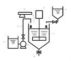
- one main reaction vessel 1 having a stirring mechanism 2 is provided with a solution supply tank 5 having a valve 3 for supplying various solutions and a pump 4 and a powder. It is preferable to use an apparatus provided with a body supply device 6, a dropping tank 8 having a valve-attached pipe 7, and a valve-attached pipe 9 that discharges a slurry containing the produced double fluoride phosphor.
- the stirrer is attached to the reaction vessel.
- a type in which a stirring blade is attached to the stirring shaft and the entire stirring shaft rotates is preferable.
- the shape of the stirring blade can be arbitrarily selected, but examples thereof include a flat plate shape (without or with an inclination) and an anchor shape.
- the solution in the reaction vessel is stirred at a rotational speed of 0.5 times / second to 100 times / second. Preferably, it is 1 to 10 times / second.
- a dripping tank is provided above the reaction vessel so that the liquid can be added to the reaction vessel by opening a valve, or a pump or the like is provided to control the flow rate to the reaction vessel so that the liquid can be added. Or you can choose either.
- a valve, or a pump or the like is provided to control the flow rate to the reaction vessel so that the liquid can be added. Or you can choose either.
- the powder feeder is necessary to add the powder raw material to the reaction solution in the reaction vessel. It is desirable that the powder supply device also has a mechanism capable of controlling the supply amount of the powder so that the substance can be added while observing the state of dissolution or the raw material of the alkali metal A is added as a powder and reacted.
- a slurry discharge pipe is necessary. The discharged slurry is subjected to solid-liquid separation by methods such as filtration, centrifugation, and decantation.
- the double fluoride phosphor of the present invention can be obtained as a solid product.
- the solid product after the solid-liquid separation can be subjected to a treatment such as washing and solvent replacement, if necessary, and can be dried by vacuum drying or the like.
- the phosphor obtained by the production method of the present invention is a bifluoride phosphor having Mn as an emission center, and emits red light when excited with blue (400 to 480 nm, for example, 450 nm) light.
- An emission spectrum having the strongest peak around 630 nm and consisting of several sharp linewidth peaks is shown.
- the absorptance for light at 450 nm is 0.7 or more, preferably 0.71 to 0.85, and the internal quantum efficiency is 0.8 or more, preferably 0.82. 0.92 and is suitable as a red phosphor for a white LED using a blue LED as an excitation source.
- Examples 1 to 3 are examples of K 2 SiF 6 : Mn
- Example 4 is an example of K 2 TiF 6 : Mn.
- a hydrofluoric acid aqueous solution in which manganese (II) was dissolved was placed on the anode side of the reaction tank, and a hydrofluoric acid aqueous solution was placed on the cathode side. Both electrodes were connected to a power source, and electrolysis was performed at a voltage of 3 V and a current of 0.75 A. After the electrolysis, an excessive solution of potassium fluoride saturated with an aqueous hydrofluoric acid solution was added to the reaction solution on the anode side. The produced yellow solid product was separated by filtration and collected to obtain K 2 MnF 6 .
- Example 1 The reaction apparatus shown in FIG. 1 was prepared. First, 10,000 cm 3 of water was measured and charged into the reaction vessel. While stirring by starting the stirrer attached to the reaction vessel, 25,000 cm 3 of 50% hydrofluoric acid (SA-X, 50% HF manufactured by Stella Chemifa) was reacted using a pump from the acid solution supply tank. The solution was fed into the container. While continuing the stirring, 810 g of silicon dioxide (Nippil VN3, SiO 2 manufactured by Tosoh Silica) was gradually supplied from the powder supply device on the upper side of the reaction vessel. SiO 2 was dissolved in the HF solution in the reaction vessel.
- SA-X 50% hydrofluoric acid
- SA-X 50% HF manufactured by Stella Chemifa
- K 2 MnF 6 prepared by the method of the above Reference Example was supplied from the powder supply device to the reaction vessel and dissolved in the liquid in the vessel.
- 10,000 cm 3 of 50% HF was charged into a dropping tank, and 2,036 g of potassium fluoride (anhydrous potassium fluoride, KF manufactured by Stella Chemifa) was added and dissolved therein.
- the rotation speed of the stirrer attached to the reaction vessel was adjusted to 200 rotations / minute (3.33 rotations / second).
- the KF solution was dropped from the dropping tank at a substantially constant rate over 1 minute 40 seconds. A light orange precipitate was formed in the liquid in the reaction vessel.
- Example 2 In the process of Example 1, instead of dissolving SiO 2 from the powder supply device, 40% hydrofluoric acid (40% H 2 SiF 6 manufactured by Morita Chemical Co., Ltd.) from the acid solution supply tank 3,520 cm 3 was fed and mixed. Thereafter, the same operation as in Example 1 was carried out to obtain 2,860 g of K 2 SiF 6 : Mn phosphor powder.
- Example 4 The same reactor shown in FIG. 1 as in Examples 1 to 3 was used. First, 20,000 cm 3 of water was measured and charged into the reaction vessel. While the stirrer attached to the reaction vessel was started and stirred, 50% HF 15,000 cm 3 was fed from the acid solution supply tank to the reaction vessel using a pump. With continued stirring, 1,433 g of titanium dioxide (high purity product TCA-123P, TiO 2 manufactured by Sakai Chemical Industry Co., Ltd.) was gradually fed from the powder feeder on the upper side of the reaction vessel. TiO 2 was dissolved in the HF solution in the reaction vessel.
- TCA-123P high purity product manufactured by Sakai Chemical Industry Co., Ltd.
- the phosphor was obtained as a pale orange powder of 3,980 g of K 2 TiF 6 : Mn by liquid removal, acetone washing and drying.
Landscapes
- Chemical & Material Sciences (AREA)
- Organic Chemistry (AREA)
- Inorganic Chemistry (AREA)
- Engineering & Computer Science (AREA)
- Materials Engineering (AREA)
- Life Sciences & Earth Sciences (AREA)
- Environmental & Geological Engineering (AREA)
- General Life Sciences & Earth Sciences (AREA)
- Geology (AREA)
- Luminescent Compositions (AREA)
- Led Device Packages (AREA)
Abstract
下記式(I) A2MF6:Mn (I) (式中、MはSi、Ti、Zr、Hf、Ge及びSnから選ばれる1種又は2種以上の4価元素、AはLi、Na、K、Rb及びCsから選ばれ、かつ少なくともNa及び/又はKを含む1種又は2種以上のアルカリ金属である。) で表されるMn賦活複フッ化物赤色蛍光体の製造において、水に原料となる各種成分を順次溶かし込み、得られた水溶液から最終的に上記赤色蛍光体を溶液中で析出させることを特徴とする複フッ化物蛍光体の製造方法に関するものであり、本発明によれば、一つの反応容器に対して原料を次々に加えていくことができるため、複フッ化物蛍光体を合理的で高い生産性で製造することができる。
Description
本発明は、青色LED用赤色フッ化物蛍光体として有用な式A2MF6:Mn(式中、MはSi、Ti、Zr、Hf、Ge及びSnから選ばれる1種又は2種以上の4価元素、AはLi、Na、K、Rb及びCsから選ばれ、かつ少なくともNa及び/又はKを含む1種又は2種以上のアルカリ金属である。)で表されるMn賦活複フッ化物赤色蛍光体(複フッ化物蛍光体)及びその製造方法に関する。
白色LED(Light Emitting Diode)の演色性向上、あるいは白色LEDを液晶ディスプレイのバックライトとして用いる場合の色再現性の向上の目的で、近紫外から青色のLEDに相当する光で励起されて赤色に発光する蛍光体が必要とされ、研究が進められている。この中で特表2009-528429号公報(特許文献1)には、A2MF6(AはNa,K,Rb等、MはSi,Ge,Ti等)などの式で表される複フッ化物にMnを添加したもの(複フッ化物蛍光体)が有用であることが記載されている。
上記蛍光体の製造方法については、特許文献1では構成各元素を全て溶解又は分散させたフッ化水素酸溶液を蒸発濃縮させて析出させる方法が開示されている。別の製法として、米国特許第3576756号明細書(特許文献2)には、構成各元素をそれぞれ溶解させたフッ化水素酸溶液を混合後、水溶性有機溶剤であるアセトンを加えて溶解度を低下させることにより析出させる方法が開示されている。更に、特許第4582259号公報(特許文献3)、及び特開2012-224536号公報(特許文献4)には、上記式における元素Mと、元素Aをそれぞれ別々の、フッ化水素酸を含む溶液に溶解し、そのどちらかにMnを添加しておいたものを改めて混合することにより蛍光体を析出させる方法が開示されている。
以上に述べた既知のMn添加A2MF6(AはNa,K,Rb等、MはSi,Ge,Ti等)複フッ化物蛍光体の製造工程は、実験室での少量合成には適用できる。しかし、工業的に大規模で実施するには更に検討が必要である。既知の方法のうちでは量産化に適性が高いと思われる水系溶液の混合による方法(特許第4582259号公報、特開2012-224536号公報)の場合でも、実際の工業的製造装置を念頭に置いた製造工程の検討は途上である。
本発明は、上記事情に鑑みなされたもので、工業化・量産に適した、複フッ化物蛍光体の製造方法、及びこの製造方法によって製造された複フッ化物蛍光体を提供することを目的とする。
本発明者らは、上記目的を達成するべく、複フッ化物蛍光体の製造工程における物質の流れに着目し、合理的に効率よく製造できる工程を鋭意検討を行った結果、撹拌装置を設えた主反応容器に水を入れ、これに式A2MF6:Mn(但し、A及びMは上記の通り)で示される複フッ化物蛍光体を製造するための原料を順次溶かし込むこと、特に水にフッ化水素酸を投入した後、Mを含む化合物、Aを含む化合物とMnを含む化合物又はAとMnを含む化合物を投入、撹拌、溶解し、更にこれにAのフッ化物又はこれを溶解したフッ化水素酸溶液を添加して、この添加領域に上記複フッ化物蛍光体の微粒子を析出させる方法が高生産性を有し、合理性の高い方法であることを知見し、本発明をなすに至った。
従って、本発明は、下記複フッ化物蛍光体の製造方法及び該蛍光体を提供する。
〔1〕 下記式(I)
A2MF6:Mn (I)
(式中、MはSi、Ti、Zr、Hf、Ge及びSnから選ばれる1種又は2種以上の4価元素、AはLi、Na、K、Rb及びCsから選ばれ、かつ少なくともNa及び/又はKを含む1種又は2種以上のアルカリ金属である。)
で表されるMn賦活複フッ化物赤色蛍光体の製造において、水に原料となる各種成分を順次溶かし込み、得られた水溶液から最終的に上記赤色蛍光体を溶液中で析出させることを特徴とする複フッ化物蛍光体の製造方法。
〔2〕 容器に水を準備し、これにフッ化水素酸を投入し、次にM(但し、Mは上記の通り)を含む化合物を投入して撹拌、溶解し、次いでA(但し、Aは上記の通り)を含む化合物とMnを含む化合物又はA(但し、Aは上記の通り)とMnとを含む化合物を投入して撹拌、溶解してベース溶液を調製し、最後にこのベース溶液を撹拌しながらA(但し、Aは上記の通り)のフッ化物又は該フッ化物を溶解したフッ化水素酸溶液からなる添加用剤を添加して、ベース溶液中にA2MF6:Mn(但し、A及びMは上記の通り)を析出させることを特徴とする〔1〕記載の複フッ化物蛍光体の製造方法。
〔3〕 ベース溶液を上記添加用剤の添加の際に撹拌機により0.5~100回/秒の範囲の回転数で撹拌することを特徴とする〔2〕記載の複フッ化物蛍光体の製造方法。
〔4〕 添加用剤を、毎秒該添加用剤の全量の1/500~1/10の範囲の一定量で添加することを特徴とする〔2〕又は〔3〕記載の複フッ化物蛍光体の製造方法。
〔5〕
撹拌機構を有する一つの主反応容器に、各種溶液を供給するバルブ付配管及びポンプと、粉体供給装置と、生成した複フッ化物蛍光体を含むスラリーを排出するバルブ付配管とが付設された装置を用いて複フッ化物蛍光体を製造することを特徴とする〔1〕~〔4〕のいずれかに記載の複フッ化物蛍光体の製造方法。
〔6〕
〔1〕~〔5〕のいずれかに記載の製造方法によって得られ、内部量子効率が0.8以上で、吸収率が0.7以上であることを特徴とする式A2MF6:Mn(但し、A及びMは上記の通り)で示される青色LED用赤色複フッ化物蛍光体。
〔1〕 下記式(I)
A2MF6:Mn (I)
(式中、MはSi、Ti、Zr、Hf、Ge及びSnから選ばれる1種又は2種以上の4価元素、AはLi、Na、K、Rb及びCsから選ばれ、かつ少なくともNa及び/又はKを含む1種又は2種以上のアルカリ金属である。)
で表されるMn賦活複フッ化物赤色蛍光体の製造において、水に原料となる各種成分を順次溶かし込み、得られた水溶液から最終的に上記赤色蛍光体を溶液中で析出させることを特徴とする複フッ化物蛍光体の製造方法。
〔2〕 容器に水を準備し、これにフッ化水素酸を投入し、次にM(但し、Mは上記の通り)を含む化合物を投入して撹拌、溶解し、次いでA(但し、Aは上記の通り)を含む化合物とMnを含む化合物又はA(但し、Aは上記の通り)とMnとを含む化合物を投入して撹拌、溶解してベース溶液を調製し、最後にこのベース溶液を撹拌しながらA(但し、Aは上記の通り)のフッ化物又は該フッ化物を溶解したフッ化水素酸溶液からなる添加用剤を添加して、ベース溶液中にA2MF6:Mn(但し、A及びMは上記の通り)を析出させることを特徴とする〔1〕記載の複フッ化物蛍光体の製造方法。
〔3〕 ベース溶液を上記添加用剤の添加の際に撹拌機により0.5~100回/秒の範囲の回転数で撹拌することを特徴とする〔2〕記載の複フッ化物蛍光体の製造方法。
〔4〕 添加用剤を、毎秒該添加用剤の全量の1/500~1/10の範囲の一定量で添加することを特徴とする〔2〕又は〔3〕記載の複フッ化物蛍光体の製造方法。
〔5〕
撹拌機構を有する一つの主反応容器に、各種溶液を供給するバルブ付配管及びポンプと、粉体供給装置と、生成した複フッ化物蛍光体を含むスラリーを排出するバルブ付配管とが付設された装置を用いて複フッ化物蛍光体を製造することを特徴とする〔1〕~〔4〕のいずれかに記載の複フッ化物蛍光体の製造方法。
〔6〕
〔1〕~〔5〕のいずれかに記載の製造方法によって得られ、内部量子効率が0.8以上で、吸収率が0.7以上であることを特徴とする式A2MF6:Mn(但し、A及びMは上記の通り)で示される青色LED用赤色複フッ化物蛍光体。
本発明に係る製造方法は、一つの反応容器に対して原料を次々に加えていくことができるため、複フッ化物蛍光体を合理的で高い生産性で製造することができる。
本発明に係る製造方法は、下記式(I)
A2MF6:Mn (I)
(式中、MはSi、Ti、Zr、Hf、Ge及びSnから選ばれる1種又は2種以上の4価元素、AはLi、Na、K、Rb及びCsから選ばれ、かつ少なくともNa及び/又はKを含む1種又は2種以上のアルカリ金属である。)
で示される複フッ化物蛍光体を得るための方法である。
ここで、MとしてはSi、Ti又はGe、特にSi又はTiが好ましく、またAとしてはNa又はKが好ましい。
A2MF6:Mn (I)
(式中、MはSi、Ti、Zr、Hf、Ge及びSnから選ばれる1種又は2種以上の4価元素、AはLi、Na、K、Rb及びCsから選ばれ、かつ少なくともNa及び/又はKを含む1種又は2種以上のアルカリ金属である。)
で示される複フッ化物蛍光体を得るための方法である。
ここで、MとしてはSi、Ti又はGe、特にSi又はTiが好ましく、またAとしてはNa又はKが好ましい。
本発明の製造方法は、水に原料となる各種成分を順次溶かし込み、得られた水溶液から最終的に上記式(I)の赤色蛍光体を析出させるものである。
この場合、原料としては、M源(4価元素源)、A源(アルカリ金属源)、Mn源、フッ素源、更には反応媒質としてフッ化水素酸を用いる。これらの原料を水に溶解させて反応させ、蛍光体を沈殿として得る。この溶解させる順序は限定的でないが、他のものがすべて溶解しているところへ、アルカリ金属Aを加える方法が好ましい。また、溶解しやすいようにフッ化水素酸はMの源及びMnの源に先立って加えることが好ましい。
この場合、原料としては、M源(4価元素源)、A源(アルカリ金属源)、Mn源、フッ素源、更には反応媒質としてフッ化水素酸を用いる。これらの原料を水に溶解させて反応させ、蛍光体を沈殿として得る。この溶解させる順序は限定的でないが、他のものがすべて溶解しているところへ、アルカリ金属Aを加える方法が好ましい。また、溶解しやすいようにフッ化水素酸はMの源及びMnの源に先立って加えることが好ましい。
4価元素Mの源としては、フッ化物、酸化物、水酸化物、炭酸塩などを用いることができ、好ましくは酸化物、フッ化物であり、これらは1種単独で又は2種以上を組み合せて用いることができる。例を挙げれば、SiO2、TiO2などである。これらをフッ化水素酸水溶液と共に水に溶解させると、実質的に元素Mのポリフルオロ酸塩を含む水溶液となっている。またH2SiF6などのポリフルオロ酸塩の溶液を入手して使用することもできる。
マンガンの原料としては、マンガンのフッ化物、炭酸塩、酸化物、水酸化物などを用いることができるが、AとMnとを含む化合物(フッ化物、酸化物、塩化物等)の形態で用いることが好適であり、マンガンの酸化状態と溶解しやすさの点からA2MnF6で表される複フッ化物や、A2MnO3で表される複酸化物が好ましい。実例を挙げれば、K2MnF6などである。
アルカリ金属A(AはLi、Na、K、Rb及びCsから選ばれる1種又は2種以上、少なくともNa及び/又はKを含む)の源としては、フッ化物AF、フッ化水素塩AHF2、硝酸塩ANO3、硫酸塩A2SO4、硫酸水素塩AHSO4、炭酸塩A2CO3、炭酸水素塩AHCO3及び水酸化物AOHから選ばれる化合物を、必要に応じてフッ化水素(フッ化水素酸水溶液)と共に水に溶解させて水溶液として調製することができる。一方、固体の場合は、フッ化物AF、フッ化水素塩AHF2、硝酸塩ANO3、硫酸塩A2SO4、硫酸水素塩AHSO4、炭酸塩A2CO3、炭酸水素塩AHCO3及び水酸化物AOHから選ばれる化合物を、固体として準備すればよい。好ましいのはフッ化物又はフッ化水素塩である。
上記原料を用いて複フッ化物蛍光体を製造する好適な方法としては、まず反応容器に水を入れ、更にこれにフッ化水素酸を投入する。この場合、フッ化水素酸の濃度は、後述するベース溶液中、10~50質量%、特に15~45質量%であることが好ましい。
次に、M(但し、Mは上記の通り)を含む化合物を投入して撹拌、溶解する。これらMの化合物を上記フッ化水素酸水溶液に溶解する場合の濃度は、後述するベース溶液中、0.02~1.0モル/リットル、特に0.05~0.5モル/リットルであることが好ましい。
次いで、A(但し、Aは上記の通り)を含む化合物とMnを含む化合物、好ましくはAとMnとを含む化合物の1種又は2種以上を投入して撹拌、溶解し、これによってベース溶液を調製する。この場合、Aの濃度、Mnの濃度は、それぞれベース溶液中0.00005~0.4モル/リットル、特に0.0001~0.2モル/リットルであることが好ましい。
最後に、このベース溶液を撹拌しながらA(但し、Aは上記の通り)のフッ化物又は該フッ化物を溶解したフッ化水素酸溶液を添加用剤として添加する。この場合、フッ化物としては、フッ化ナトリウム、フッ化水素ナトリウム、フッ化カリウム、フッ化水素カリウムが挙げられ、特にフッ化水素ナトリウム又はフッ化水素カリウムが好ましい。また、このフッ化水素酸溶液中におけるフッ化水素酸の濃度はA原料としてフッ化物、フッ化水素塩以外を用いた場合はAの濃度と同じかそれ以上、特にAの濃度の2倍以上であることが好ましい。A原料としてフッ化物、又はフッ化水素塩を用いた場合はフッ化水素酸の濃度は限定的でない。アルカリ金属Aの濃度は0.25モル/リットル以上、特に0.5モル/リットル以上であることが好ましい。なお、添加するアルカリ金属Aの量は、ベース溶液中のMとMnの合計に対し、2.0~10.0(モル比)、特に2.0~5.0(モル比)であることが好ましい。
反応物質がすべて混合された状態での濃度は、元素MとMnの合計の濃度で、0.02~1.0モル/リットルが好ましい。より好ましくは0.05~0.5モル/リットルである。
また、反応物質がすべて混合された状態での4価元素MとMnの合計とアルカリ金属Aの比は、A/(M+Mn)=2.0~10.0(モル比)、特に2.0~5.0(モル比)とすることが好ましい。
反応系に加えるMnのMに対する比は、Mn/(M+Mn)=0.002~0.4(モル比)、特に0.005~0.2(モル比)が好ましい。
また、反応物質がすべて混合された状態での4価元素MとMnの合計とアルカリ金属Aの比は、A/(M+Mn)=2.0~10.0(モル比)、特に2.0~5.0(モル比)とすることが好ましい。
反応系に加えるMnのMに対する比は、Mn/(M+Mn)=0.002~0.4(モル比)、特に0.005~0.2(モル比)が好ましい。
反応中の液の温度は-20~100℃の範囲で、加熱又は冷却して行うことができる。フッ化水素のガスの揮発を抑制する意味では60℃以下、特に50℃以下が好ましい。
本発明の製造方法を具現化するための反応装置は、反応容器、酸溶液供給槽、撹拌機、滴下槽、ポンプ、粉体供給装置、スラリー排出配管を備えていることが必要である。
本発明の製造方法を具現化するための反応装置は、反応容器、酸溶液供給槽、撹拌機、滴下槽、ポンプ、粉体供給装置、スラリー排出配管を備えていることが必要である。
より具体的には、製造装置として図1に示すように、撹拌機構2を有する一つの主反応容器1に、各種溶液を供給するバルブ付配管3及びポンプ4を有する溶液供給槽5と、粉体供給装置6と、バルブ付配管7を有する滴下槽8と、生成した複フッ化物蛍光体を含むスラリーを排出するバルブ付配管9とが付設された装置を用いることが好ましい。
このうち撹拌機は、反応容器に取り付けられる。撹拌軸に撹拌翼が取り付けられ、撹拌軸ごと回転する形式が好ましい。撹拌翼の形状は任意に選択できるが、例を挙げれば平板状(傾斜なし又は有り)、アンカー状などである。反応中は、反応容器中の溶液を回転数が、0.5回/秒から100回/秒の範囲で撹拌する。好ましくは1~10回/秒である。
滴下槽は、反応容器の上方に設けて、バルブを開けることにより液を反応容器に加えられるようにするか、又はポンプなどを設けて反応容器に流速を制御して液を添加できるようにするか、いずれかを選択できる。アルカリ金属Aを溶解したフッ化水素酸溶液を溶液に滴下する際に、投入フッ化水素酸溶液全量の1/500から1/10の量を一定で毎秒溶液中に滴下するようにできることが好ましい。この速度はより好ましくは1/200~1/20である。
粉体供給装置は粉末の原料を反応容器中の反応液に添加するために必要である。物質を溶解の様子を見ながら加えられるように、又はアルカリ金属Aの原料を粉末で加えて反応させるために、この粉体供給装置も粉体の供給量を制御できる機構のものが望ましい。沈殿として得られた蛍光体を固液分離するために、スラリー排出配管は必要である。排出されたスラリーは、ろ別、遠心分離、デカンテーションなどの方法により固液分離する。
本発明の複フッ化物蛍光体を固体生成物として得ることができる。固液分離後の固体生成物は、必要に応じて、洗浄、溶媒置換などの処理を実施することができ、また、真空乾燥などによって乾燥することができる。
本発明の製造方法によって得られた蛍光体はMnを発光中心とする複フッ化物蛍光体であり、青色(400~480nm、1例として450nm)光の励起により赤色発光を示す。630nm前後に最強ピークを有し、数本の鋭い線幅のピークからなる発光スペクトルを示す。本発明の範囲の標準的な条件で製造した場合、450nmの光に対する吸収率が0.7以上、好ましくは0.71~0.85、内部量子効率が0.8以上、好ましくは0.82~0.92を示し、青色LEDを励起源とする白色LED用の赤色蛍光体として好適である。
以下に、実施例及び比較例を挙げて、本発明を更に具体的に説明するが、本発明はこれらに限定されるものではない。なお、実施例1~3はK2SiF6:Mn、実施例4はK2TiF6:Mnの例である。
[参考例]
[K2MnF6の調製]
丸善株式会社発行、日本化学会編、新実験化学講座8「無機化合物の合成III」、1977年発行、1166ページ(非特許文献1)に記載されている方法に準拠し、以下の方法で調製した。
塩化ビニル樹脂製の反応槽の中央にフッ素樹脂系イオン交換膜の仕切り(隔膜)を設け、イオン交換膜を挟む2室の各々に、いずれも白金板からなる陽極と陰極を設置した。反応槽の陽極側にフッ化マンガン(II)を溶解させたフッ化水素酸水溶液、陰極側にフッ化水素酸水溶液を入れた。両極を電源につなぎ、電圧3V、電流0.75Aで電解を行った。電解を終えた後、陽極側の反応液に、フッ化水素酸水溶液に飽和させたフッ化カリウムの溶液を過剰に加えた。生成した黄色の固体生成物を濾別、回収し、K2MnF6を得た。
[K2MnF6の調製]
丸善株式会社発行、日本化学会編、新実験化学講座8「無機化合物の合成III」、1977年発行、1166ページ(非特許文献1)に記載されている方法に準拠し、以下の方法で調製した。
塩化ビニル樹脂製の反応槽の中央にフッ素樹脂系イオン交換膜の仕切り(隔膜)を設け、イオン交換膜を挟む2室の各々に、いずれも白金板からなる陽極と陰極を設置した。反応槽の陽極側にフッ化マンガン(II)を溶解させたフッ化水素酸水溶液、陰極側にフッ化水素酸水溶液を入れた。両極を電源につなぎ、電圧3V、電流0.75Aで電解を行った。電解を終えた後、陽極側の反応液に、フッ化水素酸水溶液に飽和させたフッ化カリウムの溶液を過剰に加えた。生成した黄色の固体生成物を濾別、回収し、K2MnF6を得た。
[実施例1]
図1に示す反応装置を用意した。まず、反応容器に水を10,000cm3計量して仕込んだ。反応容器に取り付けた撹拌機を起動して撹拌をしながら、酸溶液供給槽から、50%フッ化水素酸(ステラケミファ製SA-X、50%HF)25,000cm3をポンプを用いて反応容器に送液して仕込んだ。撹拌を続けたまま、二酸化ケイ素(東ソー・シリカ製NipsilVN3、SiO2)の810gを反応容器の上側にある粉体供給装置から少しずつ供給した。反応容器内のHF溶液にSiO2は溶解した。続いて、上記参考例の方法で作成したK2MnF6200gを粉体供給装置から反応容器に供給して、容器内の液に溶解させた。
ここまでの間に、並行して50%HFの10,000cm3を滴下槽に仕込み、ここにフッ化カリウム(ステラケミファ製無水フッ化カリウム、KF)2,036gを加えて溶解しておいた。反応容器につけた撹拌機の回転数を200回転/分(3.33回転/秒)に合わせた。滴下槽からKF溶液をほぼ一定の速度で1分40秒かけて滴下した。反応容器中の液には、淡橙色の沈殿が生じていた。
約10分後に、反応容器下部のスラリー排出配管のバルブを開け、配管がつながっている減圧濾過器にスラリーを送り、沈殿を濾別した。十分脱液後、ケーキ状になった沈殿に浸る位のアセトンを注いで洗浄した。ケーキを回収し真空乾燥した。2,850gの淡橙色粉末としてK2SiF6:Mnの蛍光体が得られた。
得られた粉末製品の粒度分布を、気流分散式レーザー回折法粒度分布測定器(HELOS&RODOS、Sympatec社製)によって測定した。その結果、粒径15.9μm以下の粒子が全体積の10%(D10=15.9μm)、粒径34.7μm以下の粒子が全体積の50%(D50=34.7μm)、粒径49.8μm以下の粒子が全体積の90%を占めた(D90=49.8μm)。
図1に示す反応装置を用意した。まず、反応容器に水を10,000cm3計量して仕込んだ。反応容器に取り付けた撹拌機を起動して撹拌をしながら、酸溶液供給槽から、50%フッ化水素酸(ステラケミファ製SA-X、50%HF)25,000cm3をポンプを用いて反応容器に送液して仕込んだ。撹拌を続けたまま、二酸化ケイ素(東ソー・シリカ製NipsilVN3、SiO2)の810gを反応容器の上側にある粉体供給装置から少しずつ供給した。反応容器内のHF溶液にSiO2は溶解した。続いて、上記参考例の方法で作成したK2MnF6200gを粉体供給装置から反応容器に供給して、容器内の液に溶解させた。
ここまでの間に、並行して50%HFの10,000cm3を滴下槽に仕込み、ここにフッ化カリウム(ステラケミファ製無水フッ化カリウム、KF)2,036gを加えて溶解しておいた。反応容器につけた撹拌機の回転数を200回転/分(3.33回転/秒)に合わせた。滴下槽からKF溶液をほぼ一定の速度で1分40秒かけて滴下した。反応容器中の液には、淡橙色の沈殿が生じていた。
約10分後に、反応容器下部のスラリー排出配管のバルブを開け、配管がつながっている減圧濾過器にスラリーを送り、沈殿を濾別した。十分脱液後、ケーキ状になった沈殿に浸る位のアセトンを注いで洗浄した。ケーキを回収し真空乾燥した。2,850gの淡橙色粉末としてK2SiF6:Mnの蛍光体が得られた。
得られた粉末製品の粒度分布を、気流分散式レーザー回折法粒度分布測定器(HELOS&RODOS、Sympatec社製)によって測定した。その結果、粒径15.9μm以下の粒子が全体積の10%(D10=15.9μm)、粒径34.7μm以下の粒子が全体積の50%(D50=34.7μm)、粒径49.8μm以下の粒子が全体積の90%を占めた(D90=49.8μm)。
[実施例2]
実施例1の工程のうち、SiO2を粉体供給装置から投入して溶解することに代えて、酸溶液供給槽から40%ケイフッ化水素酸(森田化学工業製、40%H2SiF6)3,520cm3を送液して混合した。あとは実施例1と同様に操作を進め、2,860gのK2SiF6:Mnの蛍光体粉末を得た。実施例1と同様にして測定した粒度分布の結果は、D10=16.1μm、D50=34.9μm、D90=49.2μmであった。
実施例1の工程のうち、SiO2を粉体供給装置から投入して溶解することに代えて、酸溶液供給槽から40%ケイフッ化水素酸(森田化学工業製、40%H2SiF6)3,520cm3を送液して混合した。あとは実施例1と同様に操作を進め、2,860gのK2SiF6:Mnの蛍光体粉末を得た。実施例1と同様にして測定した粒度分布の結果は、D10=16.1μm、D50=34.9μm、D90=49.2μmであった。
[実施例3]
実施例1の工程のうち、KFを50%HFに溶解して滴下槽から加えることをやめ、その代わりにフッ化水素カリウム(ステラケミファ製酸性フッ化カリウム、KHF2)の粉末2,737gを粉体供給装置から供給して反応させた。撹拌機の回転数を300回転/分(5回転/秒)にあわせた撹拌しているところへ、粉体供給装置からKHF2粉末を1分間かけて反応容器中の溶液に加えた。反応容器中ではKHF2が溶解しながら反応して淡橙色の沈殿が生じていった。約15分撹拌したのち、実施例1と同様に濾過、回収、乾燥してK2SiF6:Mnの蛍光体粉末2,835gを得た。実施例1と同様にして測定した粒度分布の結果は、D10=13.5μm、D50=32.9μm、D90=50.8μmであった。
実施例1の工程のうち、KFを50%HFに溶解して滴下槽から加えることをやめ、その代わりにフッ化水素カリウム(ステラケミファ製酸性フッ化カリウム、KHF2)の粉末2,737gを粉体供給装置から供給して反応させた。撹拌機の回転数を300回転/分(5回転/秒)にあわせた撹拌しているところへ、粉体供給装置からKHF2粉末を1分間かけて反応容器中の溶液に加えた。反応容器中ではKHF2が溶解しながら反応して淡橙色の沈殿が生じていった。約15分撹拌したのち、実施例1と同様に濾過、回収、乾燥してK2SiF6:Mnの蛍光体粉末2,835gを得た。実施例1と同様にして測定した粒度分布の結果は、D10=13.5μm、D50=32.9μm、D90=50.8μmであった。
[実施例4]
実施例1~3と同じ図1に示す反応装置を用いた。まず、反応容器に水を20,000cm3計量して仕込んだ。反応容器に取り付けた撹拌機を起動して撹拌をしながら、酸溶液供給槽から、50%HF15,000cm3をポンプを用いて反応容器に送液して仕込んだ。撹拌を続けたまま、二酸化チタン(堺化学工業製高純度品TCA-123P、TiO2)の1,433gを反応容器の上側にある粉体供給装置から少しずつ供給した。反応容器内のHF溶液にTiO2は溶解した。続いて、上記参考例の方法で作成したK2MnF6356gを粉体供給装置から反応容器に供給して、容器内の液に溶解させた。
ここまでの間に、並行して50%HFの5,000cm3と水5,000cm3を滴下槽に仕込み、ここにKF3,556gを加えて溶解しておいた。反応容器につけた撹拌機の回転数を200回転/分(3.33回転/秒)に合わせた。滴下槽からKF溶液をほぼ一定の速度で1分35秒かけて滴下した。反応容器中の液には、淡橙色の沈殿が生じていた。
約10分後に、実施例1と同様にして濾過操作を行った。更に脱液、アセトン洗浄、乾燥をして3,980gのK2TiF6:Mnの淡橙色粉末として蛍光体が得られた。実施例1と同様にして測定した粒度分布の結果は、D10=16.1μm、D50=38.9μm、D90=69.3μmであった。
実施例1~3と同じ図1に示す反応装置を用いた。まず、反応容器に水を20,000cm3計量して仕込んだ。反応容器に取り付けた撹拌機を起動して撹拌をしながら、酸溶液供給槽から、50%HF15,000cm3をポンプを用いて反応容器に送液して仕込んだ。撹拌を続けたまま、二酸化チタン(堺化学工業製高純度品TCA-123P、TiO2)の1,433gを反応容器の上側にある粉体供給装置から少しずつ供給した。反応容器内のHF溶液にTiO2は溶解した。続いて、上記参考例の方法で作成したK2MnF6356gを粉体供給装置から反応容器に供給して、容器内の液に溶解させた。
ここまでの間に、並行して50%HFの5,000cm3と水5,000cm3を滴下槽に仕込み、ここにKF3,556gを加えて溶解しておいた。反応容器につけた撹拌機の回転数を200回転/分(3.33回転/秒)に合わせた。滴下槽からKF溶液をほぼ一定の速度で1分35秒かけて滴下した。反応容器中の液には、淡橙色の沈殿が生じていた。
約10分後に、実施例1と同様にして濾過操作を行った。更に脱液、アセトン洗浄、乾燥をして3,980gのK2TiF6:Mnの淡橙色粉末として蛍光体が得られた。実施例1と同様にして測定した粒度分布の結果は、D10=16.1μm、D50=38.9μm、D90=69.3μmであった。
[比較例1]
40%のH2SiF6水溶液23cm3を、まず50%HF266cm3と混合した。これに、予め先述の参考例の方法で作製したK2MnF6粉末を1.33g加えて撹拌し溶解させた(溶液A)。
これとは別に、フッ化水素カリウム21.05gを50%HF68cm3、純水127cm3と混合し溶解させた(溶液B)。
溶液Aを室温(16℃)にて撹拌しながら、溶液B(17℃)を加えた。液の温度は26℃になり、淡榿色の沈殿(K2SiF6:Mn)が生じた。更に10分撹拌を続けたのち、この沈殿をブフナー漏斗でろ別し、できるだけ脱液した。更にアセトンで洗浄し、脱液、真空乾燥して、粉末製品K2SiF6:Mn18.01gを得た。
実施例1と同様にして測定した粒度分布の結果は、D10=10.5μm、D50=23.8μm、D90=35.4μmであった。
40%のH2SiF6水溶液23cm3を、まず50%HF266cm3と混合した。これに、予め先述の参考例の方法で作製したK2MnF6粉末を1.33g加えて撹拌し溶解させた(溶液A)。
これとは別に、フッ化水素カリウム21.05gを50%HF68cm3、純水127cm3と混合し溶解させた(溶液B)。
溶液Aを室温(16℃)にて撹拌しながら、溶液B(17℃)を加えた。液の温度は26℃になり、淡榿色の沈殿(K2SiF6:Mn)が生じた。更に10分撹拌を続けたのち、この沈殿をブフナー漏斗でろ別し、できるだけ脱液した。更にアセトンで洗浄し、脱液、真空乾燥して、粉末製品K2SiF6:Mn18.01gを得た。
実施例1と同様にして測定した粒度分布の結果は、D10=10.5μm、D50=23.8μm、D90=35.4μmであった。
[比較例2]
40%のH2SiF6水溶液23cm3を、まず50%HF146cm3と混合した。これに、予め先述の参考例の方法で作製したK2MnF6粉末を1.33g加えて撹拌し溶解させた(溶液A)。
これとは別に、フッ化水素カリウム21.05gを50%HF180cm3、純水90cm3と混合し溶解させた(溶液B)。
溶液Bを室温(16℃)にて撹拌しながら、溶液A(17℃)を加えた。液の温度は25℃になり、淡榿色の沈殿(K2SiF6:Mn)が生じた。更に10分撹拌を続けたのち、この沈殿をブフナー漏斗でろ別し、できるだけ脱液した。更にアセトンで洗浄し、脱液、真空乾燥して、粉末製品K2SiF6:Mn17.88gを得た。
実施例1と同様にして測定した粒度分布の結果は、D10=4.2μm、D50=11.3μm、D90=17.3μmであった。
40%のH2SiF6水溶液23cm3を、まず50%HF146cm3と混合した。これに、予め先述の参考例の方法で作製したK2MnF6粉末を1.33g加えて撹拌し溶解させた(溶液A)。
これとは別に、フッ化水素カリウム21.05gを50%HF180cm3、純水90cm3と混合し溶解させた(溶液B)。
溶液Bを室温(16℃)にて撹拌しながら、溶液A(17℃)を加えた。液の温度は25℃になり、淡榿色の沈殿(K2SiF6:Mn)が生じた。更に10分撹拌を続けたのち、この沈殿をブフナー漏斗でろ別し、できるだけ脱液した。更にアセトンで洗浄し、脱液、真空乾燥して、粉末製品K2SiF6:Mn17.88gを得た。
実施例1と同様にして測定した粒度分布の結果は、D10=4.2μm、D50=11.3μm、D90=17.3μmであった。
[実験例]
実施例により得られた粉末試料の発光スペクトル及び吸収率、量子効率を、量子効率測定装置QE1100(大塚電子(株)製)を用いて、励起波長450nmで測定した。吸収率と量子効率を表1に示す。
実施例により得られた粉末試料の発光スペクトル及び吸収率、量子効率を、量子効率測定装置QE1100(大塚電子(株)製)を用いて、励起波長450nmで測定した。吸収率と量子効率を表1に示す。

1 容器
2 撹拌機構
3、7、9 バルブ付配管
4 ポンプ
5 供給槽
6 粉体供給装置
8 滴下槽
2 撹拌機構
3、7、9 バルブ付配管
4 ポンプ
5 供給槽
6 粉体供給装置
8 滴下槽
Claims (6)
- 下記式(I)
A2MF6:Mn (I)
(式中、MはSi、Ti、Zr、Hf、Ge及びSnから選ばれる1種又は2種以上の4価元素、AはLi、Na、K、Rb及びCsから選ばれ、かつ少なくともNa及び/又はKを含む1種又は2種以上のアルカリ金属である。)
で表されるMn賦活複フッ化物赤色蛍光体の製造において、水に原料となる各種成分を順次溶かし込み、得られた水溶液から最終的に上記赤色蛍光体を溶液中で析出させることを特徴とする複フッ化物蛍光体の製造方法。 - 容器に水を準備し、これにフッ化水素酸を投入し、次にM(但し、Mは上記の通り)を含む化合物を投入して撹拌、溶解し、次いでA(但し、Aは上記の通り)を含む化合物とMnを含む化合物又はA(但し、Aは上記の通り)とMnとを含む化合物を投入して撹拌、溶解してベース溶液を調製し、最後にこのベース溶液を撹拌しながらA(但し、Aは上記の通り)のフッ化物又は該フッ化物を溶解したフッ化水素酸溶液からなる添加用剤を添加して、ベース溶液中にA2MF6:Mn(但し、A及びMは上記の通り)を析出させることを特徴とする請求項1記載の複フッ化物蛍光体の製造方法。
- ベース溶液を上記添加用剤の添加の際に撹拌機により0.5~100回/秒の範囲の回転数で撹拌することを特徴とする請求項2記載の複フッ化物蛍光体の製造方法。
- 添加用剤を、毎秒該添加用剤の全量の1/500~1/10の範囲の一定量で添加することを特徴とする請求項2又は3記載の複フッ化物蛍光体の製造方法。
- 撹拌機構を有する一つの主反応容器に、各種溶液を供給するバルブ付配管及びポンプと、粉体供給装置と、生成した複フッ化物蛍光体を含むスラリーを排出するバルブ付配管とが付設された装置を用いて複フッ化物蛍光体を製造することを特徴とする請求項1~4のいずれか1項記載の複フッ化物蛍光体の製造方法。
- 請求項1~5のいずれか1項記載の製造方法によって得られ、内部量子効率が0.8以上で、吸収率が0.7以上であることを特徴とする式A2MF6:Mn(但し、A及びMは上記の通り)で示される青色LED用赤色複フッ化物蛍光体。
Applications Claiming Priority (2)
| Application Number | Priority Date | Filing Date | Title |
|---|---|---|---|
| JP2014-015673 | 2014-01-30 | ||
| JP2014015673A JP2015140425A (ja) | 2014-01-30 | 2014-01-30 | 複フッ化物蛍光体及びその製造方法 |
Publications (1)
| Publication Number | Publication Date |
|---|---|
| WO2015115193A1 true WO2015115193A1 (ja) | 2015-08-06 |
Family
ID=53756770
Family Applications (1)
| Application Number | Title | Priority Date | Filing Date |
|---|---|---|---|
| PCT/JP2015/050918 Ceased WO2015115193A1 (ja) | 2014-01-30 | 2015-01-15 | 複フッ化物蛍光体及びその製造方法 |
Country Status (3)
| Country | Link |
|---|---|
| JP (1) | JP2015140425A (ja) |
| TW (1) | TW201540812A (ja) |
| WO (1) | WO2015115193A1 (ja) |
Cited By (2)
| Publication number | Priority date | Publication date | Assignee | Title |
|---|---|---|---|---|
| CN106433637A (zh) * | 2015-08-04 | 2017-02-22 | 云南民族大学 | 一种新型Mn4+激活的高色纯度氟化物红色发光材料制备方法 |
| CN118496847A (zh) * | 2024-03-31 | 2024-08-16 | 江门市科恒实业股份有限公司 | 一种高亮度的荧光粉及其制备方法 |
Families Citing this family (7)
| Publication number | Priority date | Publication date | Assignee | Title |
|---|---|---|---|---|
| US9512357B2 (en) * | 2014-07-22 | 2016-12-06 | General Electric Company | Red-emitting phosphors, associated processes and devices |
| KR101722052B1 (ko) * | 2015-08-13 | 2017-04-03 | 한국화학연구원 | 형광체의 제조방법 및 이에 따라 제조되는 형광체를 포함하는 발광소자 |
| KR102624694B1 (ko) | 2015-09-30 | 2024-01-12 | 덴카 주식회사 | 불화물 형광체, 발광 장치 및 불화물 형광체의 제조 방법 |
| TWI564367B (zh) * | 2015-11-16 | 2017-01-01 | 隆達電子股份有限公司 | 氟化物螢光粉、其製備方法及包含其之發光裝置與背光模組 |
| JP2018137321A (ja) * | 2017-02-21 | 2018-08-30 | シャープ株式会社 | 発光装置および画像表示装置 |
| JP6273394B1 (ja) * | 2017-06-14 | 2018-01-31 | デンカ株式会社 | フッ化物蛍光体とそれを用いた発光装置 |
| JP6273395B1 (ja) * | 2017-06-14 | 2018-01-31 | デンカ株式会社 | フッ化物蛍光体とそれを用いた発光装置 |
Citations (6)
| Publication number | Priority date | Publication date | Assignee | Title |
|---|---|---|---|---|
| JP2010209311A (ja) * | 2008-09-05 | 2010-09-24 | Mitsubishi Chemicals Corp | 蛍光体及びその製造方法と、その蛍光体を用いた蛍光体含有組成物及び発光装置、並びに、その発光装置を用いた画像表示装置及び照明装置 |
| JP2010254933A (ja) * | 2009-04-28 | 2010-11-11 | Mitsubishi Chemicals Corp | 蛍光体と、その蛍光体を用いた蛍光体含有組成物及び発光装置、並びに、その発光装置を用いた画像表示装置及び照明装置 |
| JP2011012091A (ja) * | 2009-06-30 | 2011-01-20 | Mitsubishi Chemicals Corp | 蛍光体及びその製造方法と、その蛍光体を用いた蛍光体含有組成物及び発光装置、並びに、その発光装置を用いた画像表示装置及び照明装置 |
| JP2012224536A (ja) * | 2011-04-08 | 2012-11-15 | Shin-Etsu Chemical Co Ltd | 複フッ化物及び複フッ化物蛍光体の製造方法 |
| JP2013014715A (ja) * | 2011-07-06 | 2013-01-24 | Nichia Corp | フッ化物蛍光体及びそのフッ化物蛍光体を用いた発光装置 |
| JP2013060506A (ja) * | 2011-09-13 | 2013-04-04 | Nichia Corp | フッ化物蛍光体及びそれを用いた発光装置 |
-
2014
- 2014-01-30 JP JP2014015673A patent/JP2015140425A/ja active Pending
-
2015
- 2015-01-15 WO PCT/JP2015/050918 patent/WO2015115193A1/ja not_active Ceased
- 2015-01-29 TW TW104103047A patent/TW201540812A/zh unknown
Patent Citations (6)
| Publication number | Priority date | Publication date | Assignee | Title |
|---|---|---|---|---|
| JP2010209311A (ja) * | 2008-09-05 | 2010-09-24 | Mitsubishi Chemicals Corp | 蛍光体及びその製造方法と、その蛍光体を用いた蛍光体含有組成物及び発光装置、並びに、その発光装置を用いた画像表示装置及び照明装置 |
| JP2010254933A (ja) * | 2009-04-28 | 2010-11-11 | Mitsubishi Chemicals Corp | 蛍光体と、その蛍光体を用いた蛍光体含有組成物及び発光装置、並びに、その発光装置を用いた画像表示装置及び照明装置 |
| JP2011012091A (ja) * | 2009-06-30 | 2011-01-20 | Mitsubishi Chemicals Corp | 蛍光体及びその製造方法と、その蛍光体を用いた蛍光体含有組成物及び発光装置、並びに、その発光装置を用いた画像表示装置及び照明装置 |
| JP2012224536A (ja) * | 2011-04-08 | 2012-11-15 | Shin-Etsu Chemical Co Ltd | 複フッ化物及び複フッ化物蛍光体の製造方法 |
| JP2013014715A (ja) * | 2011-07-06 | 2013-01-24 | Nichia Corp | フッ化物蛍光体及びそのフッ化物蛍光体を用いた発光装置 |
| JP2013060506A (ja) * | 2011-09-13 | 2013-04-04 | Nichia Corp | フッ化物蛍光体及びそれを用いた発光装置 |
Cited By (3)
| Publication number | Priority date | Publication date | Assignee | Title |
|---|---|---|---|---|
| CN106433637A (zh) * | 2015-08-04 | 2017-02-22 | 云南民族大学 | 一种新型Mn4+激活的高色纯度氟化物红色发光材料制备方法 |
| CN106433637B (zh) * | 2015-08-04 | 2018-09-14 | 云南民族大学 | 一种新型Mn4+激活的高色纯度氟化物红色发光材料制备方法 |
| CN118496847A (zh) * | 2024-03-31 | 2024-08-16 | 江门市科恒实业股份有限公司 | 一种高亮度的荧光粉及其制备方法 |
Also Published As
| Publication number | Publication date |
|---|---|
| JP2015140425A (ja) | 2015-08-03 |
| TW201540812A (zh) | 2015-11-01 |
Similar Documents
| Publication | Publication Date | Title |
|---|---|---|
| JP2015140425A (ja) | 複フッ化物蛍光体及びその製造方法 | |
| JP5845999B2 (ja) | 複フッ化物蛍光体の製造方法 | |
| JP6394307B2 (ja) | 複フッ化物蛍光体及びその製造方法 | |
| JP5804149B2 (ja) | 複フッ化物蛍光体の製造方法及び処理方法 | |
| JP6614072B2 (ja) | Mn賦活複フッ化物蛍光体及びその製造方法 | |
| KR102693295B1 (ko) | Mn 부활 복불화물 형광체 및 그의 제조 방법 | |
| JP6119623B2 (ja) | 複フッ化物蛍光体の製造方法 | |
| JP5828366B2 (ja) | 複フッ化物蛍光体の製造方法 | |
| JP2018062596A (ja) | 赤色蛍光体及びその製造方法 | |
| WO2015115188A1 (ja) | ヘキサフルオロマンガン(iv)酸塩及び複フッ化物蛍光体並びにそれらの製造方法 | |
| JP6112029B2 (ja) | 複フッ化物蛍光体の製造方法 | |
| JP2017008263A (ja) | 蛍光体の製造方法 |
Legal Events
| Date | Code | Title | Description |
|---|---|---|---|
| 121 | Ep: the epo has been informed by wipo that ep was designated in this application |
Ref document number: 15743798 Country of ref document: EP Kind code of ref document: A1 |
|
| NENP | Non-entry into the national phase |
Ref country code: DE |
|
| 122 | Ep: pct application non-entry in european phase |
Ref document number: 15743798 Country of ref document: EP Kind code of ref document: A1 |