WO2015115140A1 - ランフラットタイヤ - Google Patents
ランフラットタイヤ Download PDFInfo
- Publication number
- WO2015115140A1 WO2015115140A1 PCT/JP2015/050274 JP2015050274W WO2015115140A1 WO 2015115140 A1 WO2015115140 A1 WO 2015115140A1 JP 2015050274 W JP2015050274 W JP 2015050274W WO 2015115140 A1 WO2015115140 A1 WO 2015115140A1
- Authority
- WO
- WIPO (PCT)
- Prior art keywords
- tire
- carcass
- thickness
- section height
- cross
- Prior art date
- Legal status (The legal status is an assumption and is not a legal conclusion. Google has not performed a legal analysis and makes no representation as to the accuracy of the status listed.)
- Ceased
Links
Images

Classifications
-
- B—PERFORMING OPERATIONS; TRANSPORTING
- B60—VEHICLES IN GENERAL
- B60C—VEHICLE TYRES; TYRE INFLATION; TYRE CHANGING; CONNECTING VALVES TO INFLATABLE ELASTIC BODIES IN GENERAL; DEVICES OR ARRANGEMENTS RELATED TO TYRES
- B60C17/00—Tyres characterised by means enabling restricted operation in damaged or deflated condition; Accessories therefor
- B60C17/0009—Tyres characterised by means enabling restricted operation in damaged or deflated condition; Accessories therefor comprising sidewall rubber inserts, e.g. crescent shaped inserts
-
- B—PERFORMING OPERATIONS; TRANSPORTING
- B60—VEHICLES IN GENERAL
- B60C—VEHICLE TYRES; TYRE INFLATION; TYRE CHANGING; CONNECTING VALVES TO INFLATABLE ELASTIC BODIES IN GENERAL; DEVICES OR ARRANGEMENTS RELATED TO TYRES
- B60C11/00—Tyre tread bands; Tread patterns; Anti-skid inserts
-
- B—PERFORMING OPERATIONS; TRANSPORTING
- B60—VEHICLES IN GENERAL
- B60C—VEHICLE TYRES; TYRE INFLATION; TYRE CHANGING; CONNECTING VALVES TO INFLATABLE ELASTIC BODIES IN GENERAL; DEVICES OR ARRANGEMENTS RELATED TO TYRES
- B60C15/00—Tyre beads, e.g. ply turn-up or overlap
- B60C15/06—Flipper strips, fillers, or chafing strips and reinforcing layers for the construction of the bead
- B60C15/0603—Flipper strips, fillers, or chafing strips and reinforcing layers for the construction of the bead characterised by features of the bead filler or apex
-
- B—PERFORMING OPERATIONS; TRANSPORTING
- B60—VEHICLES IN GENERAL
- B60C—VEHICLE TYRES; TYRE INFLATION; TYRE CHANGING; CONNECTING VALVES TO INFLATABLE ELASTIC BODIES IN GENERAL; DEVICES OR ARRANGEMENTS RELATED TO TYRES
- B60C9/00—Reinforcements or ply arrangement of pneumatic tyres
- B60C9/02—Carcasses
-
- B—PERFORMING OPERATIONS; TRANSPORTING
- B60—VEHICLES IN GENERAL
- B60C—VEHICLE TYRES; TYRE INFLATION; TYRE CHANGING; CONNECTING VALVES TO INFLATABLE ELASTIC BODIES IN GENERAL; DEVICES OR ARRANGEMENTS RELATED TO TYRES
- B60C17/00—Tyres characterised by means enabling restricted operation in damaged or deflated condition; Accessories therefor
- B60C17/0009—Tyres characterised by means enabling restricted operation in damaged or deflated condition; Accessories therefor comprising sidewall rubber inserts, e.g. crescent shaped inserts
- B60C17/0027—Tyres characterised by means enabling restricted operation in damaged or deflated condition; Accessories therefor comprising sidewall rubber inserts, e.g. crescent shaped inserts comprising portions of different rubbers in a single insert
-
- B—PERFORMING OPERATIONS; TRANSPORTING
- B60—VEHICLES IN GENERAL
- B60C—VEHICLE TYRES; TYRE INFLATION; TYRE CHANGING; CONNECTING VALVES TO INFLATABLE ELASTIC BODIES IN GENERAL; DEVICES OR ARRANGEMENTS RELATED TO TYRES
- B60C13/00—Tyre sidewalls; Protecting, decorating, marking, or the like, thereof
- B60C2013/005—Physical properties of the sidewall rubber
- B60C2013/007—Thickness
-
- B—PERFORMING OPERATIONS; TRANSPORTING
- B60—VEHICLES IN GENERAL
- B60C—VEHICLE TYRES; TYRE INFLATION; TYRE CHANGING; CONNECTING VALVES TO INFLATABLE ELASTIC BODIES IN GENERAL; DEVICES OR ARRANGEMENTS RELATED TO TYRES
- B60C15/00—Tyre beads, e.g. ply turn-up or overlap
- B60C15/0009—Tyre beads, e.g. ply turn-up or overlap features of the carcass terminal portion
- B60C2015/009—Height of the carcass terminal portion defined in terms of a numerical value or ratio in proportion to section height
-
- B—PERFORMING OPERATIONS; TRANSPORTING
- B60—VEHICLES IN GENERAL
- B60C—VEHICLE TYRES; TYRE INFLATION; TYRE CHANGING; CONNECTING VALVES TO INFLATABLE ELASTIC BODIES IN GENERAL; DEVICES OR ARRANGEMENTS RELATED TO TYRES
- B60C15/00—Tyre beads, e.g. ply turn-up or overlap
- B60C15/06—Flipper strips, fillers, or chafing strips and reinforcing layers for the construction of the bead
- B60C15/0603—Flipper strips, fillers, or chafing strips and reinforcing layers for the construction of the bead characterised by features of the bead filler or apex
- B60C2015/061—Dimensions of the bead filler in terms of numerical values or ratio in proportion to section height
-
- B—PERFORMING OPERATIONS; TRANSPORTING
- B60—VEHICLES IN GENERAL
- B60C—VEHICLE TYRES; TYRE INFLATION; TYRE CHANGING; CONNECTING VALVES TO INFLATABLE ELASTIC BODIES IN GENERAL; DEVICES OR ARRANGEMENTS RELATED TO TYRES
- B60C17/00—Tyres characterised by means enabling restricted operation in damaged or deflated condition; Accessories therefor
- B60C17/0009—Tyres characterised by means enabling restricted operation in damaged or deflated condition; Accessories therefor comprising sidewall rubber inserts, e.g. crescent shaped inserts
- B60C2017/0054—Physical properties or dimensions of the inserts
- B60C2017/0072—Thickness
Definitions
- the present invention relates to a side-reinforced run-flat tire.
- Japanese Patent Laid-Open No. 2012-116212 discloses a side reinforcement in which a tire side portion is reinforced with a side reinforcing rubber (tire reinforcing layer) as a run flat tire that can safely travel a certain distance even when the internal pressure is reduced due to puncture or the like.
- a run-flat tire of the type is disclosed.
- An object of the present invention is to suppress a tensile force acting on a side reinforcing layer when a buckling occurs in a tire side portion in a run flat tire having a high tire section height (section height).
- a carcass straddling between a pair of bead parts, the bead part and the tread part are connected, and the carcass
- the maximum width of the carcass having the maximum width is provided on the tire side portion positioned on the outer side in the tire radial direction from the position of 40% of the tire cross-section height, and on the inner side in the tire width direction of the carcass.
- % Side reinforcing layer having a thickness of 65% or less of the thickness at the carcass maximum width position.
- the present invention is configured as described above, in a run flat tire having a high tire cross section height (section height), it is possible to suppress a tensile force acting on the side reinforcing layer when buckling occurs in the tire side portion.
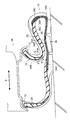
- FIG. 1 is a tire half sectional view showing one side of a cut surface obtained by cutting a run flat tire according to an embodiment of the present invention along a tire axial direction.
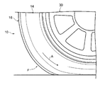
- FIG. 2 is a side view of the tire when the run flat tire shown in FIG. 1 in a running state is viewed from the tire axial direction.
- It is tire sectional drawing which shows the cross section which cut
- a run-flat tire 10 (hereinafter referred to as “tire 10”) according to an embodiment of the present invention will be described with reference to the drawings.
- an arrow X indicates the width direction of the tire 10 (tire width direction)
- an arrow R indicates the radial direction of the tire 10 (tire radial direction).
- the tire width direction here refers to a direction parallel to the rotation axis of the tire 10 and is also referred to as a tire axial direction.
- the tire radial direction refers to a direction orthogonal to the rotation axis of the tire 10.
- Reference sign CL indicates the equator plane of the tire 10 (tire equator plane).
- the rotation axis side of the tire 10 along the tire radial direction is “inner side in the tire radial direction”, and the opposite side of the tire 10 along the tire radial direction is “outer side in the tire radial direction”. It describes.
- the equatorial plane CL side of the tire 10 along the tire width direction is referred to as “inner side in the tire width direction”, and the side opposite to the equatorial plane CL along the tire width direction is referred to as “outer side in the tire width direction”.
- FIG. 1 shows one side of a cross section along the tire axial direction of the tire 10 when it is mounted on a standard rim 30 (shown by a two-dot chain line in FIG. 1) and filled with standard air pressure.
- the standard rim here is a rim defined in the Year 2013 edition of JATMA (Japan Automobile Tire Association).
- the standard air pressure is an air pressure corresponding to the maximum load capacity of Year Book 2013 version of JATMA (Japan Automobile Tire Association).
- the load is the maximum load (maximum load capacity) of a single wheel at the applicable size described in the following standard
- the internal pressure is the maximum load of a single wheel (specified in the following standard)
- the rim is a standard rim (or “Applied Rim” or “Recommended Rim”) in an applicable size described in the following standard.
- the standards are determined by industry standards that are valid in the region where the tire is produced or used. For example, in the United States, “The Tire and Rim Association Inc. Year Book” in Europe, in Europe “The European Tire and Rim Technical Standards Manual” in Japan, and in Japan, “Japan Tire” in Japan. Has been.
- the tire 10 of the present embodiment is a tire having a tire cross-section height SH (section height) of 115 mm or more and a flatness ratio of 55 or more.
- SH section height
- the present invention is not limited to this configuration, and the flatness ratio is 55. It may be less.
- tire cross section height refers to a length that is 1 ⁇ 2 of the difference between the tire outer diameter and the rim diameter, as defined by the Year 2013 edition of JATMA (Japan Automobile Tire Association).
- the run-flat tire 10 includes a carcass straddling a pair of bead portions 12 (only one bead portion 12 is shown in FIG. 1) and the bead portion 12. 22, a tire side portion 14 that connects the bead portion 12 and the tread portion 16, and a side reinforcing rubber 26 as a side reinforcing layer.
- a bead core 18 is embedded in each of the pair of bead portions 12, and a carcass 22 straddles the pair of bead cores 18.
- the end side of the carcass 22 is locked to the bead core 18.
- the end portion side of the carcass 22 is folded and locked around the bead core 18 from the tire inner side to the outer side, and the end portion 22C of the folded portion 22B is in contact with the carcass main body portion 22A.
- the carcass 22 extends in a toroidal shape from one bead core 18 to the other bead core 18 to constitute a tire skeleton.
- one end portion and the other end portion of the carcass 22 are folded and locked around the bead core 18, but not limited thereto, for example, a plurality of bead core pieces are arranged in the bead portion 12, The carcass 22 may be sandwiched between the plurality of bead core pieces.
- a belt layer 24A, a cap layer 24B, and a layer layer 24C are disposed outside the carcass main body 22A in the tire radial direction.
- the cap layer 24B covers the entire belt layer 24A, and the layer layer 24C covers the vicinity of the end of the belt layer 24A.
- the carcass 22, the belt layer 24A, the cap layer 24B, and the layer layer 24C can have the structure of each member used in a conventionally known run flat tire.
- a bead filler 20 extending from the bead core 18 to the outer side in the tire radial direction along the outer surface 220 of the carcass 22 is embedded.
- the bead filler 20 is disposed in a region surrounded by the carcass main body 22A and the folded portion 22B.
- the outer surface 220 of the carcass 22 is a surface on the tire outer side in the carcass main body portion 22A, and is a surface on the inner side of the tire in the folded portion 22B.
- the end portion 20 ⁇ / b> A of the bead filler 20 on the outer side in the tire radial direction enters the tire side portion 14. Further, the bead filler 20 is reduced in thickness toward the outer side in the tire radial direction.
- the height BH of the bead filler 20 is set within a range of 30 to 50% of the tire cross-section height SH, and is set to 42% as an example in the present embodiment. .
- the height BH of the bead filler 20 is higher than 50% of the tire cross-section height SH, the tire side portion 14 becomes hard and the ride comfort is deteriorated, and the height BH of the bead filler 20 is 30 of the tire cross-section height SH. If it is lower than%, run-flat durability is reduced.
- the “bead filler height BH” as used herein refers to the bead filler from the intersection of the bead seat extension line and the bead base extension line when the tire 10 is assembled to the standard rim 30 and the internal pressure is the standard air pressure.
- the height BH of the bead filler 20 is set within a range of 30 to 50% of the tire cross-section height SH, and the end portion 20A of the bead filler 20 is located from the maximum width position P of the carcass 22. Is also on the inner side in the tire radial direction.
- the “maximum width position P of the carcass 22” here refers to a position where the distance between the carcass 22 is the largest along the tire axial direction of the tire 10, and the maximum width position P is the tire cross-sectional height. It is located on the outer side in the tire radial direction from the position Q of 40% of SH.
- the tire side portion 14 is provided with a side reinforcing rubber 26 that reinforces the tire side portion 14 on the inner side in the tire axial direction of the carcass 22.
- the side reinforcing rubber 26 extends in the tire radial direction along the inner surface 22I of the carcass 22. Further, the side reinforcing rubber 26 has a shape whose thickness decreases as it goes to the bead core 18 side and the tread portion 16 side, for example, a substantially crescent shape.
- the end portion 26 ⁇ / b> A on the tread portion 16 side overlaps the tread portion 16 with the carcass 22 (carcass main body portion 22 ⁇ / b> A) interposed therebetween, and the end portion 26 ⁇ / b> B on the bead core 18 side overlaps with the bead filler 20.
- the side reinforcing rubber 26 is made of hard rubber, and is a reinforcing rubber for running a predetermined distance while supporting the weight of the vehicle and the occupant when the internal pressure of the tire 10 decreases due to puncture or the like.
- the thickness GB of the side reinforcing rubber 26 at the position Q of 40% of the tire cross-section height (section height) SH is 65% or less of the thickness GA of the side reinforcing rubber 26 at the carcass maximum width position P.
- the “thickness of the side reinforcing rubber” is a straight line drawn vertically from the inner surface of the side reinforcing rubber 26 to the carcass 22 when the tire 10 is assembled to the standard rim 30 and the internal pressure is set to the standard air pressure. Point to the length.
- the thickness GB of the side reinforcing rubber 26 is 40% or less of the total thickness SB of the tire side portion 14 at the position Q of 40% of the tire cross-section height SH. Further, the thickness SB of the entire tire side portion 14 at the position Q of 40% of the tire cross-section height SH is 90% to 110% of the total thickness SA of the tire side portion 14 at the carcass maximum width position P. Is set. Note that the thickness SB of the entire tire side portion 14 here refers to the length of a straight line drawn from the inner surface of the side reinforcing rubber 26 to the outer peripheral surface of the tire side portion 14 vertically.
- the side reinforcing rubber mainly composed of rubber is disposed.
- the present invention is not limited to this, and may be formed of other materials, for example, thermoplastic resin or the like as a main component. May be.
- the side reinforcement rubber 26 is formed of one type of rubber member, the present invention is not limited thereto, and may be formed of a plurality of rubber members.
- the side reinforcing rubber 26 may include other materials such as fillers, short fibers, and resins as long as the rubber member is a main component.
- a durometer hardness tester is 70 to 85, and a viscoelastic spectrometer.
- an inner liner (not shown) is disposed from one bead portion 12 to the other bead portion 12.
- an inner liner having butyl rubber as a main component is disposed.
- the present invention is not limited thereto, and other rubber members or resins may be used as a main component.
- the one-layer side reinforcing rubber 26 is sandwiched between the inner liner and the carcass 22, but the present invention is not limited to this. For example, a separate carcass is provided between the inner liner and the carcass 22. Then, the side reinforcing rubber 26 may be divided.
- the distance in the tire radial direction between the lower end portion of the bead core 18 and the lower end portion of the side reinforcing rubber 26 is preferably 50 to 80% of the height of the bead filler 20. In this embodiment, as an example, It is set at 65%. If it is higher than 80%, the run-flat running performance is lowered, and if it is lower than 50%, the ride comfort is deteriorated.
- the rim guard (rim protection) is not provided.
- the present invention is not limited thereto, and a rim guard may be provided.
- the graph shown in FIG. 4 is obtained by examining the rim detachment index with respect to the tire cross-section height SH using a run flat tire in which the tire width is 215 mm and the tire cross-section height SH is changed. Since the rim detachment here occurs through buckling, it indicates that the larger the numerical value of the rim detachment index, the less likely buckling occurs. According to FIG.
- the thickness GB of the side reinforcing rubber 26 at this position Q is 65% or less of the thickness GA of the side reinforcing rubber 26 at the carcass maximum width position P, so that it acts on the side reinforcing rubber 26.
- the tensile force can be greatly reduced. Thereby, the durability of the side reinforcing rubber 26 can be improved. That is, run flat durability can be improved. Moreover, damage to the side reinforcing rubber 26 can also be suppressed.
- the thickness GB of the side reinforcing rubber 26 at the position Q where the tire cross-section height SH is 40% is formed to be 10% or more of the thickness GA of the side reinforcing rubber 26 at the carcass maximum width position P. preferable.
- the thickness GB of the side reinforcing rubber 26 at the position Q of 40% of the tire cross-section height SH is set to 40% or less of the thickness SB of the entire tire side portion 14.
- the thickness SB of the entire tire side portion 14 at the position Q of 40% of the tire cross-section height SH is 90% to 110% of the total thickness SA of the tire side portion 14 at the carcass maximum width position P.
- the thickness is set. Thereby, it can suppress that the weight of the tire 10 increases excessively, ensuring run flat durability.
- the side reinforcing rubber 26 is composed of one type of rubber, but the present invention is not limited to this configuration, and the side reinforcing rubber 26 is composed of a plurality of types of rubber. It may be configured.
- the side reinforcing rubber 26 may have a configuration in which a plurality of types of different rubbers are stacked in the tire radial direction, and the side reinforcing rubber 26 may have a configuration in which a plurality of types of different rubbers are stacked in the tire axial direction.
- the side reinforcing rubber 26 may have a configuration in which different types of rubber are stacked in the tire radial direction.
- the present invention if the thickness of the side reinforcing rubber 26 at the position Q of 40% of the tire cross-section height SH is set to 65% or less of the thickness of the side reinforcing rubber 26 at the carcass maximum width position P, the present invention. The effect of can be obtained.
- the tire size used for the evaluation is 215 / 60R17.
- Each of the tires of Examples 1 to 3 employs the same structure as that of the tire 10 of the present embodiment described above, and the tires having different side reinforcement rubber thicknesses.
- the tires of Comparative Examples 1 and 2 have the same structure as the tires of Examples 1 to 3, but the thickness of the side reinforcing rubber at a position of 40% of the tire cross-section height SH is included in the present invention. There is no tire.
- Various numerical values of Examples 1 to 3 and Comparative Examples 1 and 2 are as shown in Table 1.
- the side reinforcing rubber was evaluated for cracking properties.
- the maximum in-plane principal strain value of the inner surface of the side reinforcing rubber is calculated by simulation using the finite element method, and the maximum in-plane principal strain value of Comparative Example 1 is expressed as an index with the reference value (100). It is. Table 1 below changes GB / GA. Table 2 shows changes in GB / SB. Furthermore, Table 3 changes SB / SA.
- Example 1 As shown in Table 1, in Comparative Example 2, the ratio of the thickness GB of the side reinforcing rubber at the position of 40% of the tire cross-section height SH to the thickness GA of the side reinforcing rubber at the carcass maximum width position (GB / GA). Is 66%. On the other hand, in Example 1, GB / GA is 65%. Moreover, the cracking property of the side reinforcing rubber is greatly improved. Moreover, in Example 2 and Example 3 which made GB / GA smaller than Example 1, it turns out that the cracking property of side reinforcement rubber is improved further.
- the thickness GB of the side reinforcing rubber is set to 40% or less of the thickness SB of the entire tire side portion at the position of 40% of the tire cross-section height. Yes. Thereby, compared with the comparative example 3 which made GB / SB 45% larger than 40%, the cracking property of the side reinforcement rubber is improved.
- the thickness SB of the entire tire side portion at the position of 40% of the tire cross-sectional height is set to 90% of the thickness SA of the entire tire side portion at the carcass maximum width position. It is set in the range of ⁇ 110%.
Landscapes
- Engineering & Computer Science (AREA)
- Mechanical Engineering (AREA)
- Tires In General (AREA)
Abstract
ランフラットタイヤ(10)は、一対のビード部(12)の間に跨るカーカス(22)と、ビード部(12)とトレッド部(16)とを連結し、カーカス(22)の幅が最大となるカーカス最大幅位置がタイヤ断面高さの40%の位置よりタイヤ径方向外側に設けられたタイヤサイド部(14)と、カーカスのタイヤ幅方向内側に設けられると共に、タイヤ断面高さの40%の位置における厚さが、カーカス最大幅位置における厚さの65%以下の厚さとされたサイド補強層(26)と、を有する。
Description
本発明は、サイド補強型のランフラットタイヤに関する。
パンクなどで内圧が低下した状態でも一定距離を安全に走行可能にするランフラットタイヤとして、特開2012-116212号公報には、タイヤサイド部をサイド補強ゴム(タイヤ補強層)で補強したサイド補強型のランフラットタイヤが開示されている。
ところで、サイド補強型のランフラットタイヤでは、内圧が低下した状態での走行時(ランフラット走行時)に、車両が旋回するなどしてスリップアングルが入力されると、タイヤサイド部がタイヤ内側に折れ曲がるバックリングが発生することがある。また、タイヤ断面高さ(セクションハイト)が高いランフラットタイヤでは特にバックリングが発生しやすく、このバックリングによって、サイド補強ゴムに引張力が作用する。
本発明は、タイヤ断面高さ(セクションハイト)が高いランフラットタイヤにおいて、タイヤサイド部のバックリング発生時に、サイド補強層へ作用する引張力を抑制することを課題とする。
本発明の第1態様に係るランフラットタイヤは、タイヤ断面高さが115mm以上のランフラットタイヤにおいて、一対のビード部間に跨るカーカスと、前記ビード部とトレッド部とを連結し、前記カーカスの幅が最大となるカーカス最大幅位置がタイヤ断面高さの40%の位置よりタイヤ径方向外側に位置するタイヤサイド部と、前記カーカスのタイヤ幅方向内側に設けられると共に、タイヤ断面高さの40%の位置における厚さが、前記カーカス最大幅位置における厚さの65%以下の厚さとされたサイド補強層と、を有する。
本発明は、上記の構成としたので、タイヤ断面高さ(セクションハイト)が高いランフラットタイヤにおいて、タイヤサイド部のバックリング発生時に、サイド補強層へ作用する引張力を抑制することができる。
(ランフラットタイヤ10の構成)
以下、図を参照しながら本発明の実施形態に係るランフラットタイヤ10(以下、「タイヤ10」と称す。)について説明する。なお、図中矢印Xはタイヤ10の幅方向(タイヤ幅方向)を示し、矢印Rはタイヤ10の径方向(タイヤ径方向)を示す。ここでいうタイヤ幅方向とは、タイヤ10の回転軸と平行な方向を指し、タイヤ軸方向ともいう。また、タイヤ径方向とは、タイヤ10の回転軸と直交する方向をいう。また、符号CLはタイヤ10の赤道面(タイヤ赤道面)を示している。さらに、本実施の形態では、タイヤ径方向に沿ってタイヤ10の回転軸側を「タイヤ径方向内側」、タイヤ径方向に沿ってタイヤ10の回転軸とは反対側を「タイヤ径方向外側」と記載する。一方、タイヤ幅方向に沿ってタイヤ10の赤道面CL側を「タイヤ幅方向内側」、タイヤ幅方向に沿ってタイヤ10の赤道面CLとは反対側を「タイヤ幅方向外側」と記載する。
以下、図を参照しながら本発明の実施形態に係るランフラットタイヤ10(以下、「タイヤ10」と称す。)について説明する。なお、図中矢印Xはタイヤ10の幅方向(タイヤ幅方向)を示し、矢印Rはタイヤ10の径方向(タイヤ径方向)を示す。ここでいうタイヤ幅方向とは、タイヤ10の回転軸と平行な方向を指し、タイヤ軸方向ともいう。また、タイヤ径方向とは、タイヤ10の回転軸と直交する方向をいう。また、符号CLはタイヤ10の赤道面(タイヤ赤道面)を示している。さらに、本実施の形態では、タイヤ径方向に沿ってタイヤ10の回転軸側を「タイヤ径方向内側」、タイヤ径方向に沿ってタイヤ10の回転軸とは反対側を「タイヤ径方向外側」と記載する。一方、タイヤ幅方向に沿ってタイヤ10の赤道面CL側を「タイヤ幅方向内側」、タイヤ幅方向に沿ってタイヤ10の赤道面CLとは反対側を「タイヤ幅方向外側」と記載する。
図1は、標準リム30(図1では、二点鎖線で示している。)に装着して標準空気圧を充填したときのタイヤ10のタイヤ軸方向に沿った断面の片側を示したものである。ここでいう標準リムとは、JATMA(日本自動車タイヤ協会)のYear Book2013年度版規定のリムである。また、上記標準空気圧とは、JATMA(日本自動車タイヤ協会)のYear Book2013年度版の最大負荷能力に対応する空気圧である。なお、日本以外では、荷重とは下記規格に記載されている適用サイズにおける単輪の最大荷重(最大負荷能力)のことであり、内圧とは下記規格に記載されている単輪の最大荷重(最大負荷能力)に対応する空気圧のことであり、リムとは下記規格に記載されている適用サイズにおける標準リム(または、”Approved Rim”、”Recommended Rim”)のことである。規格は、タイヤが生産又は使用される地域に有効な産業規格によって決められている。例えば、アメリカ合衆国では、”The Tire and Rim Association Inc.のYear Book ”で、欧州では”The European Tire and Rim Technical OrganizationのStandards Manual”で、日本では日本自動車タイヤ協会の“JATMA Year Book”にて規定されている。
なお、本実施の形態のタイヤ10は、タイヤ断面高さSH(セクションハイト)が115mm以上で、偏平率が55以上のタイヤであるが、本発明はこの構成に限定されず、偏平率は55未満であってもよい。ここでいう「タイヤ断面高さ」とは、JATMA(日本自動車タイヤ協会)のYear Book2013年度版で定義されるように、タイヤ外径とリム径との差の1/2の長さを指す。
図1に示すように、本実施の形態に係るランフラットタイヤ10は、一対のビード部12(図1では、片側のビード部12のみ図示している)と、ビード部12の間に跨るカーカス22と、ビード部12とトレッド部16とを連結するタイヤサイド部14と、サイド補強層としてのサイド補強ゴム26と、を備えている。
一対のビード部12には、ビードコア18がそれぞれ埋設されており、一対のビードコア18には、カーカス22が跨っている。このカーカス22の端部側はビードコア18に係止されている。なお、本実施形態では、一例として、カーカス22の端部側がビードコア18周りにタイヤ内側から外側へ折り返されて係止されており、折返し部分22Bの端部22Cがカーカス本体部22Aに接している。また、カーカス22は、一方のビードコア18から他方のビードコア18へトロイダル状に延びてタイヤの骨格を構成している。なお、本実施形態では、カーカス22の一端部及び他端部をビードコア18周りに折り返して係止しているが、これに限らず、例えば、ビード部12に複数のビードコア片を配置して、この複数のビードコア片でカーカス22を挟み込んだ構成としてもよい。
カーカス本体部22Aのタイヤ径方向外側には、ベルト層24A、キャップ層24B及びレイヤー層24Cがそれぞれ配設されている。キャップ層24Bは、ベルト層24A全体を覆い、レイヤー層24Cはベルト層24Aの端部近傍を覆っている。なお、カーカス22、ベルト層24A、キャップ層24B及びレイヤー層24Cには、従来公知のランフラットタイヤで用いる各部材の構造を用いることができる。
ビード部12には、ビードコア18からタイヤ径方向外側へカーカス22の外面22Oに沿って延びるビードフィラー20が埋設されている。本実施の形態では、ビードフィラー20は、カーカス本体部22Aと折返し部分22Bとで囲まれた領域に配置されている。なお、カーカス22の外面22Oは、カーカス本体部22Aにおいてはタイヤ外側の面であり、折返し部分22Bにおいてはタイヤ内側の面である。また、本実施の形態では、ビードフィラー20のタイヤ径方向外側の端部20Aがタイヤサイド部14に入り込んでいる。また、ビードフィラー20は、タイヤ径方向外側に向けて厚みが減少している。
図1に示すように、ビードフィラー20の高さBHは、タイヤ断面高さSHの30~50%の範囲内に設定されており、本実施形態では、一例として、42%に設定されている。ビードフィラー20の高さBHがタイヤ断面高さSHの50%より高い場合は、タイヤサイド部14が硬くなって乗り心地が悪くなり、ビードフィラー20の高さBHがタイヤ断面高さSHの30%より低い場合は、ランフラット耐久性が低下する。なお、ここでいう「ビードフィラーの高さBH」とは、タイヤ10を標準リム30に組み付けて内圧を標準空気圧とした状態におけるビードシートの延長線とビードベースの延長線との交点からビードフィラー20の端部20Aまでのタイヤ径方向に沿って計測した長さを指している。
また、最も好ましいのは、ビードフィラー20の高さBHがタイヤ断面高さSHの30~50%の範囲内に設定され、且つ、ビードフィラー20の端部20Aがカーカス22の最大幅位置Pよりもタイヤ径方向内側にあることである。ここでいう「カーカス22の最大幅位置P」とは、タイヤ10のタイヤ軸方向に沿ってカーカス22間の距離が最も広くなる位置を指しており、この最大幅位置Pは、タイヤ断面高さSHの40%の位置Qよりタイヤ径方向外側に位置している。
タイヤサイド部14には、カーカス22のタイヤ軸方向内側にタイヤサイド部14を補強するサイド補強ゴム26が配設されている。このサイド補強ゴム26は、カーカス22の内面22Iに沿ってタイヤ径方向に延びている。また、サイド補強ゴム26は、ビードコア18側及びトレッド部16側に向かうにつれて厚さが減少する形状、例えば、略三日月形状とされている。
サイド補強ゴム26は、トレッド部16側の端部26Aがカーカス22(カーカス本体部22A)を挟んでトレッド部16と重なり、ビードコア18側の端部26Bがカーカス22を挟んでビードフィラー20と重なっている。このサイド補強ゴム26は、硬質のゴムで形成され、タイヤ10の内圧がパンクなどで減少した場合に車両及び乗員の重量を支えた状態で所定の距離を走行させるための補強ゴムである。
ここで、タイヤ断面高さ(セクションハイト)SHの40%の位置Qにおけるサイド補強ゴム26の厚さGBは、カーカス最大幅位置Pにおけるサイド補強ゴム26の厚さGAの65%以下の厚さとされている。なお、ここでいう「サイド補強ゴムの厚さ」とは、タイヤ10を標準リム30に組み付けて内圧を標準空気圧とした状態において、サイド補強ゴム26の内面から垂直にカーカス22へ引いた直線の長さを指している。
サイド補強ゴム26の厚さGBは、タイヤ断面高さSHの40%の位置Qにおけるタイヤサイド部14全体の厚さSBの40%以下の厚さとされている。また、タイヤ断面高さSHの40%の位置Qにおけるタイヤサイド部14全体の厚さSBは、カーカス最大幅位置Pにおけるタイヤサイド部14全体の厚さSAの90%~110%の厚さに設定されている。なお、ここでいうタイヤサイド部14全体の厚さSBは、サイド補強ゴム26の内面から垂直にタイヤサイド部14の外周面まで引いた直線の長さを指している。
なお、本実施形態では、ゴムを主成分とするサイド補強ゴムを配設しているが、これに限らず、他の材料で形成してもよく、例えば、熱可塑性樹脂等を主成分として形成してもよい。また、サイド補強ゴム26を1種類のゴム部材で形成しているが、これに限らず、複数のゴム部材で形成してもよい。また、サイド補強ゴム26は、ゴム部材が主成分であれば、他にフィラー、短繊維、樹脂等の材料を含んでもよい。さらに、サイド補強ゴム26及びカーカス22よりタイヤ幅方向外側を構成するゴム部材の一例として、例えば、デュロメータ硬さ試験機を用いて20℃で測定したJIS硬度が70~85で、粘弾性スペクトロメータ(例えば、東洋精機製作所製スペクトロメータ)を用いて周波数20Hz、初期歪み10%、動歪み±2%、温度60℃の条件で測定した損失係数tanδが0.10以下の物性を有するゴム部材を含んでもよい。
サイド補強ゴム26の内面には、一方のビード部12から他方のビード部12に亘って図示しないインナーライナーが配設されている。本実施形態では、一例として、ブチルゴムを主成分とするインナーライナーを配設しているが、これに限らず、他のゴム部材や、樹脂を主成分としてもよい。なお、本実施形態では、インナーライナーとカーカス22との間に1層のサイド補強ゴム26を挟んでいるが、これに限らず、例えば、インナーライナーとカーカス22との間に別途カーカスを配設し、サイド補強ゴム26を分断してもよい。
ここで、ビードコア18の下端部とサイド補強ゴム26の下端部とのタイヤ径方向の距離は、ビードフィラー20の高さの50~80%とするのが好ましく、本実施形態では、一例として、65%で設定している。80%より高いと、ランフラット走行性が低下し、50%より低いと、乗り心地が悪化する。
なお、本実施形態では、タイヤ断面高さSHが高いタイヤ10を対象としているため、リムガード(リムプロテクション)を設けていないが、これに限らず、リムガードを設けてもよい。
(作用及び効果)
次に、本実施の形態のタイヤ10の作用及び効果について説明する。図2に示すように、ランフラット走行時には、タイヤ10の接地部分が大きく撓んだ状態となる。そして、この状態でコーナリングによってスリップアングルが入力されると、撓みがタイヤ10の進行方向前側へ伝播し、踏込側部分Fが大きく撓んだ状態となる(なお、図2の矢印は、タイヤ回転方向を示したものである)。この結果、車両の旋回内側に位置するタイヤサイド部14がタイヤ10の内側に折れ曲がって、バックリングが発生することがある。
次に、本実施の形態のタイヤ10の作用及び効果について説明する。図2に示すように、ランフラット走行時には、タイヤ10の接地部分が大きく撓んだ状態となる。そして、この状態でコーナリングによってスリップアングルが入力されると、撓みがタイヤ10の進行方向前側へ伝播し、踏込側部分Fが大きく撓んだ状態となる(なお、図2の矢印は、タイヤ回転方向を示したものである)。この結果、車両の旋回内側に位置するタイヤサイド部14がタイヤ10の内側に折れ曲がって、バックリングが発生することがある。
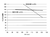
ところで、タイヤ断面高さSHが115mm以上のタイヤの場合、旋回内側に位置するタイヤにバックリングが発生しやすいことが確認されている。図4に示すグラフは、タイヤ幅を215mmにしてタイヤ断面高さSHを変更したランフラットタイヤを用いて、タイヤ断面高さSHに対するリム外れ指標を調べたものである。ここでいうリム外れは、バックリングを経て生じるため、リム外れ指標の数値が大きいほど、バックリングが発生しにくいことを示している。この図4によれば、タイヤ断面高さSHが高くなるほど、旋回内側のリム外れ指標の数値が小さくなっており、タイヤ断面高さSHが115mm以上のタイヤでは、旋回外側よりもバックリングが発生し易くなっているのが分かる。
図3に示すように、タイヤサイド部14にバックリングが発生した場合、サイド補強ゴム26の内面26Cに引張力又は圧縮力が作用する。この引張力は、タイヤ断面高さSHが40%の位置Qの近傍に矢印E及びE’方向に生じる。このため、タイヤ断面高さSHが40%の位置Qで引張力が大きくなりやすい。本実施形態では、この位置Qにおけるサイド補強ゴム26の厚さGBをカーカス最大幅位置Pにおけるサイド補強ゴム26の厚さGAの65%以下の厚さとしているので、サイド補強ゴム26に作用する引張力を大幅に減少させることができる。これにより、サイド補強ゴム26の耐久性を向上することができる。すなわち、ランフラット耐久性を向上できる。また、サイド補強ゴム26の破損も抑制することができる。
一方、サイド補強ゴム26の厚みを薄くし過ぎると、ランフラット耐久性の確保のためにビードフィラー20を厚くする必要があり、タイヤサイド部14が硬くなって乗り心地が悪化する。このため、タイヤ断面高さSHが40%の位置Qにおけるサイド補強ゴム26の厚さGBをカーカス最大幅位置Pにおけるサイド補強ゴム26の厚さGAの10%以上の厚さで形成するのが好ましい。
また、タイヤ断面高さSHの40%の位置Qにおけるサイド補強ゴム26の厚さGBを、タイヤサイド部14全体の厚さSBの40%以下としている。このように、タイヤサイド部14のサイド補強部以外の部分が厚いことで、バックリングの屈曲が緩和され、バックリング発生時にサイド補強ゴム26に引張力が作用するのを抑制することができる。
さらに、タイヤ10では、タイヤ断面高さSHの40%の位置Qにおけるタイヤサイド部14全体の厚さSBをカーカス最大幅位置Pにおけるタイヤサイド部14全体の厚さSAの90%~110%の厚さに設定している。これにより、ランフラット耐久性を確保しつつ、タイヤ10の重量が過剰に増加するのを抑制することができる。
なお、本実施形態では、図1に示すように、サイド補強ゴム26を1種類のゴムで構成しているが、本発明はこの構成に限定されず、サイド補強ゴム26を複数種類のゴムで構成してもよい。例えば、サイド補強ゴム26をタイヤ径方向に異なる複種類のゴムを重ねた構成としてもよく、サイド補強ゴム26をタイヤ軸方向に異なる複数種類のゴムを重ねた構成としてもよい。なお、サイド補強ゴム26をタイヤ径方向に異なる複種類のゴムを重ねた構成としてもよい。この場合、タイヤ断面高さSHの40%の位置Qにおけるサイド補強ゴム26の厚さをカーカス最大幅位置Pにおけるサイド補強ゴム26の厚さの65%以下の厚さに設定すれば、本発明の効果を得ることができる。
以上、本発明の実施の形態について説明したが、本発明はこうした実施の形態に限定されるものでなく、本発明の要旨を逸脱しない範囲において、種々なる態様で実施し得ることは勿論である。
(試験例)
本発明の効果を確かめるために、本発明に含まれるランフラットタイヤ(以下、単にタイヤと記載する。)を8種類(以下の実施例1~8)、本発明に含まれない比較例のタイヤを5種類(以下の比較例1~5)用意して以下の評価を行った。
本発明の効果を確かめるために、本発明に含まれるランフラットタイヤ(以下、単にタイヤと記載する。)を8種類(以下の実施例1~8)、本発明に含まれない比較例のタイヤを5種類(以下の比較例1~5)用意して以下の評価を行った。
はじめに、評価に用いた実施例1~3のタイヤ及び比較例1、2のタイヤについて説明する。なお、評価に用いたタイヤのサイズはいずれも215/60R17である。実施例1~3のタイヤは、いずれも前述の本実施の形態のタイヤ10の構造と同じ構造を採用しており、サイド補強ゴムの厚さがそれぞれ異なるタイヤである。また、比較例1、2のタイヤは、実施例1~3のタイヤと同じ構造とされているが、タイヤ断面高さSHの40%の位置におけるサイド補強ゴムの厚さが本発明に含まれないタイヤである。実施例1~3及び比較例1、2の各種数値に関しては、表1に示す通りである。
上述した実施離1~3のタイヤ及び比較例1、2のタイヤを用いて、サイド補強ゴムの割れ性について評価を行った。評価は、有限要素法を用いたシミュレーションによって、サイド補強ゴムの内面の面内主歪最大値を算出し、比較例1の面内主歪最大値を基準値(100)として指数で表したものである。以下の表1は、GB/GAを変化させたものである。また、表2は、GB/SBを変化させたものである。さらに、表3は、SB/SAを変化させたものである。
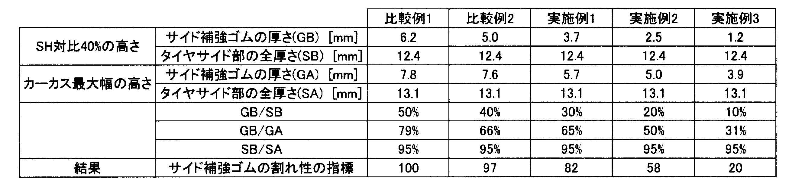
表1に示すように、比較例2では、カーカス最大幅位置におけるサイド補強ゴムの厚さGAに対するタイヤ断面高さSHの40%の位置におけるサイド補強ゴムの厚さGBの割合(GB/GA)が66%となっている。これに対して、実施例1では、GB/GAが65%となっている。また、サイド補強ゴムの割れ性が大幅に改善されている。また、GB/GAを実施例1より小さくした実施例2及び実施例3では、さらにサイド補強ゴムの割れ性が改善されているのが分かる。
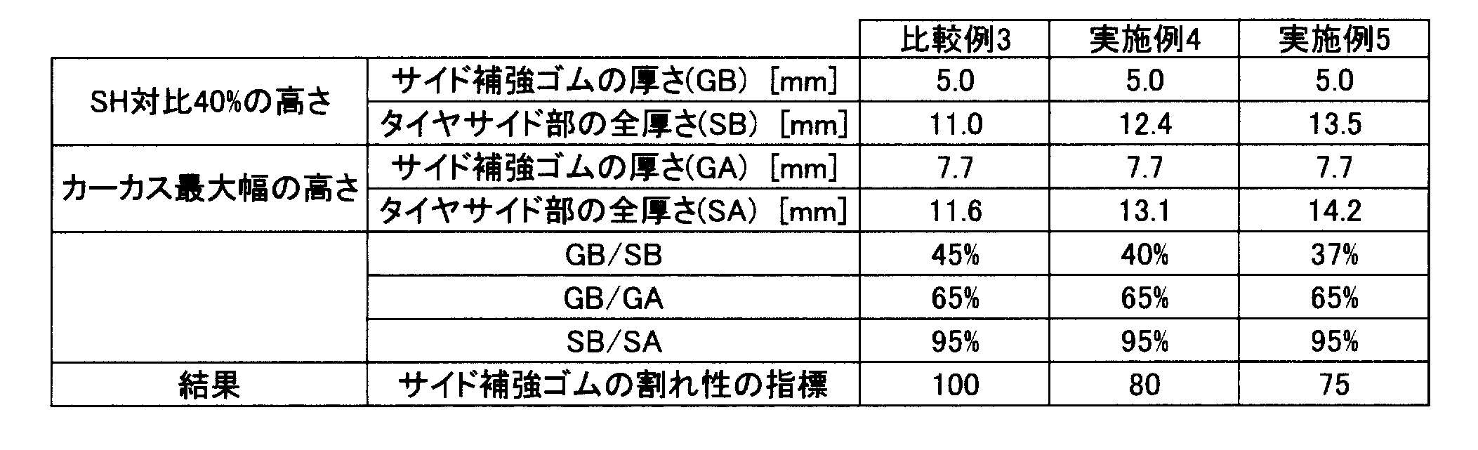
また、表2に示すように、実施例4、5のタイヤでは、タイヤ断面高さの40%の位置において、サイド補強ゴムの厚さGBをタイヤサイド部全体の厚さSBの40%以下としている。これにより、GB/SBを40%より大きい45%とした比較例3と比べて、サイド補強ゴムの割れ性が改善されている。
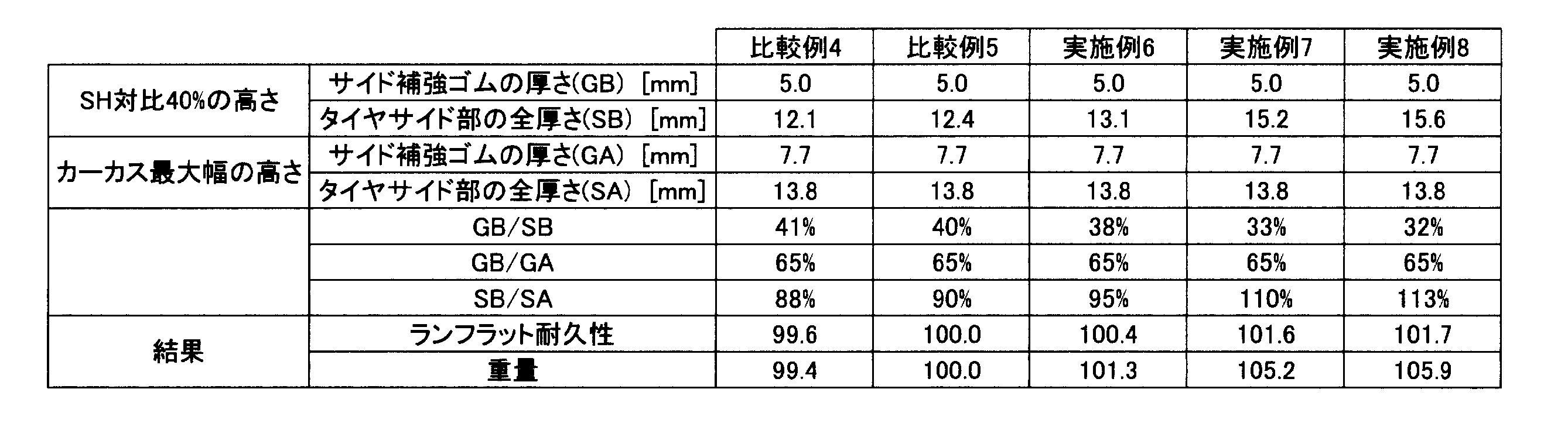
さらに、表3に示すように、実施例6~8では、タイヤ断面高さの40%の位置におけるタイヤサイド部全体の厚さSBをカーカス最大幅位置におけるタイヤサイド部全体の厚さSAの90~110%の範囲に設定している。これにより、SB/SAが88%である比較例4及び、SB/SAが113%である比較例5と比べて、ランフラット耐久性を確保しつつ、ランフラットタイヤの重量が過剰に増加するのを抑制できる。
2014年1月25日に出願された日本国特許出願2014-013597号の開示は、その全体が参照により本明細書に取り込まれる。
本明細書に記載されたすべての文献、特許出願、および技術規格は、個々の文献、特許出願、および技術規格が参照により取り込まれることが具体的かつ個々に記された場合と同程度に、本明細書中に参照により取り込まれる。
2014年1月25日に出願された日本国特許出願2014-013597号の開示は、その全体が参照により本明細書に取り込まれる。
本明細書に記載されたすべての文献、特許出願、および技術規格は、個々の文献、特許出願、および技術規格が参照により取り込まれることが具体的かつ個々に記された場合と同程度に、本明細書中に参照により取り込まれる。
Claims (3)
- タイヤ断面高さが115mm以上のランフラットタイヤにおいて、
一対のビード部間に跨るカーカスと、
前記ビード部とトレッド部とを連結し、前記カーカスの幅が最大となるカーカス最大幅位置がタイヤ断面高さの40%の位置よりタイヤ径方向外側に位置するタイヤサイド部と、
前記カーカスのタイヤ幅方向内側に設けられると共に、タイヤ断面高さの40%の位置における厚さが、前記カーカス最大幅位置における厚さの65%以下の厚さとされたサイド補強層と、
を有するランフラットタイヤ。 - タイヤ断面高さの40%の位置における前記サイド補強層の厚さが、タイヤ断面高さの40%の位置におけるタイヤサイド部全体の厚さの40%以下である請求項1に記載のランフラットタイヤ。
- タイヤ断面高さの40%の位置における前記タイヤサイド部全体の厚さは、前記カーカス最大幅位置における前記タイヤサイド部全体の厚さの90%~110%である請求項1又は2に記載のランフラットタイヤ。
Priority Applications (1)
| Application Number | Priority Date | Filing Date | Title |
|---|---|---|---|
| US15/111,816 US10414214B2 (en) | 2014-01-28 | 2015-01-07 | Run-flat tire |
Applications Claiming Priority (2)
| Application Number | Priority Date | Filing Date | Title |
|---|---|---|---|
| JP2014013597A JP6324740B2 (ja) | 2014-01-28 | 2014-01-28 | ランフラットタイヤ |
| JP2014-013597 | 2014-01-28 |
Publications (1)
| Publication Number | Publication Date |
|---|---|
| WO2015115140A1 true WO2015115140A1 (ja) | 2015-08-06 |
Family
ID=53756718
Family Applications (1)
| Application Number | Title | Priority Date | Filing Date |
|---|---|---|---|
| PCT/JP2015/050274 Ceased WO2015115140A1 (ja) | 2014-01-28 | 2015-01-07 | ランフラットタイヤ |
Country Status (3)
| Country | Link |
|---|---|
| US (1) | US10414214B2 (ja) |
| JP (1) | JP6324740B2 (ja) |
| WO (1) | WO2015115140A1 (ja) |
Cited By (1)
| Publication number | Priority date | Publication date | Assignee | Title |
|---|---|---|---|---|
| EP3202599A1 (en) * | 2016-02-05 | 2017-08-09 | Sumitomo Rubber Industries, Ltd. | Pneumatic tire |
Families Citing this family (1)
| Publication number | Priority date | Publication date | Assignee | Title |
|---|---|---|---|---|
| WO2020241237A1 (ja) * | 2019-05-28 | 2020-12-03 | 横浜ゴム株式会社 | タイヤ |
Citations (3)
| Publication number | Priority date | Publication date | Assignee | Title |
|---|---|---|---|---|
| JP2001322410A (ja) * | 2000-05-17 | 2001-11-20 | Ohtsu Tire & Rubber Co Ltd :The | 空気入りタイヤ |
| JP2006182294A (ja) * | 2004-12-28 | 2006-07-13 | Bridgestone Corp | 空気入りラジアルタイヤ |
| JP2013177115A (ja) * | 2012-02-08 | 2013-09-09 | Yokohama Rubber Co Ltd:The | 空気入りタイヤ |
Family Cites Families (7)
| Publication number | Priority date | Publication date | Assignee | Title |
|---|---|---|---|---|
| JPH0415111A (ja) * | 1990-05-07 | 1992-01-20 | Sumitomo Rubber Ind Ltd | 安全タイヤ |
| US5217549A (en) * | 1991-04-04 | 1993-06-08 | Bridgestone/Firestone, Inc. | Pneumatic safety tire |
| US5685927A (en) * | 1992-09-30 | 1997-11-11 | The Goodyear Tire & Rubber Company | Run-flat tire with wet handling design |
| JP4636194B2 (ja) * | 2009-05-18 | 2011-02-23 | 横浜ゴム株式会社 | 空気入りタイヤ及びその製造方法 |
| JP5263264B2 (ja) * | 2010-11-02 | 2013-08-14 | 横浜ゴム株式会社 | 空気入りランフラットタイヤ |
| JP5263271B2 (ja) | 2010-11-29 | 2013-08-14 | 横浜ゴム株式会社 | ランフラットタイヤ |
| US8573272B2 (en) * | 2011-09-02 | 2013-11-05 | The Goodyear Tire & Rubber Company | Self-supporting pneumatic tire |
-
2014
- 2014-01-28 JP JP2014013597A patent/JP6324740B2/ja active Active
-
2015
- 2015-01-07 US US15/111,816 patent/US10414214B2/en active Active
- 2015-01-07 WO PCT/JP2015/050274 patent/WO2015115140A1/ja not_active Ceased
Patent Citations (3)
| Publication number | Priority date | Publication date | Assignee | Title |
|---|---|---|---|---|
| JP2001322410A (ja) * | 2000-05-17 | 2001-11-20 | Ohtsu Tire & Rubber Co Ltd :The | 空気入りタイヤ |
| JP2006182294A (ja) * | 2004-12-28 | 2006-07-13 | Bridgestone Corp | 空気入りラジアルタイヤ |
| JP2013177115A (ja) * | 2012-02-08 | 2013-09-09 | Yokohama Rubber Co Ltd:The | 空気入りタイヤ |
Cited By (1)
| Publication number | Priority date | Publication date | Assignee | Title |
|---|---|---|---|---|
| EP3202599A1 (en) * | 2016-02-05 | 2017-08-09 | Sumitomo Rubber Industries, Ltd. | Pneumatic tire |
Also Published As
| Publication number | Publication date |
|---|---|
| JP2015140078A (ja) | 2015-08-03 |
| US10414214B2 (en) | 2019-09-17 |
| JP6324740B2 (ja) | 2018-05-16 |
| US20160325591A1 (en) | 2016-11-10 |
Similar Documents
| Publication | Publication Date | Title |
|---|---|---|
| CN105980175B (zh) | 缺气保用子午线轮胎 | |
| JP6454471B2 (ja) | ランフラットラジアルタイヤ | |
| JP6377390B2 (ja) | ランフラットラジアルタイヤ | |
| WO2015122092A1 (ja) | ランフラットラジアルタイヤ | |
| WO2015125387A1 (ja) | ランフラットタイヤ | |
| JP6525505B2 (ja) | ランフラットタイヤ | |
| JP6347979B2 (ja) | サイド補強型ランフラットラジアルタイヤ | |
| JP6411059B2 (ja) | 乗用車用サイド補強型ランフラットラジアルタイヤ | |
| JP6301105B2 (ja) | ランフラットラジアルタイヤ | |
| JP6324740B2 (ja) | ランフラットタイヤ | |
| WO2014199756A1 (ja) | ランフラットタイヤ | |
| JP6347978B2 (ja) | ランフラットタイヤ | |
| JP6268037B2 (ja) | ランフラットラジアルタイヤ | |
| JP6162023B2 (ja) | ランフラットラジアルタイヤ | |
| WO2021095884A1 (ja) | ランフラットタイヤ | |
| JP2015147474A (ja) | ランフラットラジアルタイヤ | |
| JP6274815B2 (ja) | ランフラットラジアルタイヤ | |
| WO2014192661A1 (ja) | 空気入りタイヤ | |
| JP2013141915A (ja) | 空気入りラジアルタイヤ |
Legal Events
| Date | Code | Title | Description |
|---|---|---|---|
| 121 | Ep: the epo has been informed by wipo that ep was designated in this application |
Ref document number: 15743288 Country of ref document: EP Kind code of ref document: A1 |
|
| WWE | Wipo information: entry into national phase |
Ref document number: 15111816 Country of ref document: US |
|
| NENP | Non-entry into the national phase |
Ref country code: DE |
|
| 122 | Ep: pct application non-entry in european phase |
Ref document number: 15743288 Country of ref document: EP Kind code of ref document: A1 |