WO2015114705A1 - ブロー成形装置およびブロー成形方法 - Google Patents
ブロー成形装置およびブロー成形方法 Download PDFInfo
- Publication number
- WO2015114705A1 WO2015114705A1 PCT/JP2014/005759 JP2014005759W WO2015114705A1 WO 2015114705 A1 WO2015114705 A1 WO 2015114705A1 JP 2014005759 W JP2014005759 W JP 2014005759W WO 2015114705 A1 WO2015114705 A1 WO 2015114705A1
- Authority
- WO
- WIPO (PCT)
- Prior art keywords
- preform
- blow molding
- liquid
- supply
- blow
- Prior art date
- Legal status (The legal status is an assumption and is not a legal conclusion. Google has not performed a legal analysis and makes no representation as to the accuracy of the status listed.)
- Ceased
Links
Images


Classifications
-
- B—PERFORMING OPERATIONS; TRANSPORTING
- B29—WORKING OF PLASTICS; WORKING OF SUBSTANCES IN A PLASTIC STATE IN GENERAL
- B29C—SHAPING OR JOINING OF PLASTICS; SHAPING OF MATERIAL IN A PLASTIC STATE, NOT OTHERWISE PROVIDED FOR; AFTER-TREATMENT OF THE SHAPED PRODUCTS, e.g. REPAIRING
- B29C49/00—Blow-moulding, i.e. blowing a preform or parison to a desired shape within a mould; Apparatus therefor
- B29C49/42—Component parts, details or accessories; Auxiliary operations
- B29C49/78—Measuring, controlling or regulating
- B29C49/783—Measuring, controlling or regulating blowing pressure
-
- B—PERFORMING OPERATIONS; TRANSPORTING
- B29—WORKING OF PLASTICS; WORKING OF SUBSTANCES IN A PLASTIC STATE IN GENERAL
- B29C—SHAPING OR JOINING OF PLASTICS; SHAPING OF MATERIAL IN A PLASTIC STATE, NOT OTHERWISE PROVIDED FOR; AFTER-TREATMENT OF THE SHAPED PRODUCTS, e.g. REPAIRING
- B29C49/00—Blow-moulding, i.e. blowing a preform or parison to a desired shape within a mould; Apparatus therefor
- B29C49/02—Combined blow-moulding and manufacture of the preform or the parison
- B29C49/06—Injection blow-moulding
-
- B—PERFORMING OPERATIONS; TRANSPORTING
- B29—WORKING OF PLASTICS; WORKING OF SUBSTANCES IN A PLASTIC STATE IN GENERAL
- B29C—SHAPING OR JOINING OF PLASTICS; SHAPING OF MATERIAL IN A PLASTIC STATE, NOT OTHERWISE PROVIDED FOR; AFTER-TREATMENT OF THE SHAPED PRODUCTS, e.g. REPAIRING
- B29C49/00—Blow-moulding, i.e. blowing a preform or parison to a desired shape within a mould; Apparatus therefor
- B29C49/08—Biaxial stretching during blow-moulding
- B29C49/10—Biaxial stretching during blow-moulding using mechanical means for prestretching
- B29C49/122—Drive means therefor
- B29C49/123—Electric drives, e.g. linear motors
-
- B—PERFORMING OPERATIONS; TRANSPORTING
- B29—WORKING OF PLASTICS; WORKING OF SUBSTANCES IN A PLASTIC STATE IN GENERAL
- B29C—SHAPING OR JOINING OF PLASTICS; SHAPING OF MATERIAL IN A PLASTIC STATE, NOT OTHERWISE PROVIDED FOR; AFTER-TREATMENT OF THE SHAPED PRODUCTS, e.g. REPAIRING
- B29C49/00—Blow-moulding, i.e. blowing a preform or parison to a desired shape within a mould; Apparatus therefor
- B29C49/42—Component parts, details or accessories; Auxiliary operations
- B29C49/46—Component parts, details or accessories; Auxiliary operations characterised by using particular environment or blow fluids other than air
-
- B—PERFORMING OPERATIONS; TRANSPORTING
- B29—WORKING OF PLASTICS; WORKING OF SUBSTANCES IN A PLASTIC STATE IN GENERAL
- B29C—SHAPING OR JOINING OF PLASTICS; SHAPING OF MATERIAL IN A PLASTIC STATE, NOT OTHERWISE PROVIDED FOR; AFTER-TREATMENT OF THE SHAPED PRODUCTS, e.g. REPAIRING
- B29C49/00—Blow-moulding, i.e. blowing a preform or parison to a desired shape within a mould; Apparatus therefor
- B29C49/02—Combined blow-moulding and manufacture of the preform or the parison
- B29C2049/023—Combined blow-moulding and manufacture of the preform or the parison using inherent heat of the preform, i.e. 1 step blow moulding
-
- B—PERFORMING OPERATIONS; TRANSPORTING
- B29—WORKING OF PLASTICS; WORKING OF SUBSTANCES IN A PLASTIC STATE IN GENERAL
- B29C—SHAPING OR JOINING OF PLASTICS; SHAPING OF MATERIAL IN A PLASTIC STATE, NOT OTHERWISE PROVIDED FOR; AFTER-TREATMENT OF THE SHAPED PRODUCTS, e.g. REPAIRING
- B29C49/00—Blow-moulding, i.e. blowing a preform or parison to a desired shape within a mould; Apparatus therefor
- B29C49/42—Component parts, details or accessories; Auxiliary operations
- B29C49/46—Component parts, details or accessories; Auxiliary operations characterised by using particular environment or blow fluids other than air
- B29C2049/4602—Blowing fluids
- B29C2049/465—Blowing fluids being incompressible
- B29C2049/4664—Blowing fluids being incompressible staying in the final article
-
- B—PERFORMING OPERATIONS; TRANSPORTING
- B29—WORKING OF PLASTICS; WORKING OF SUBSTANCES IN A PLASTIC STATE IN GENERAL
- B29C—SHAPING OR JOINING OF PLASTICS; SHAPING OF MATERIAL IN A PLASTIC STATE, NOT OTHERWISE PROVIDED FOR; AFTER-TREATMENT OF THE SHAPED PRODUCTS, e.g. REPAIRING
- B29C49/00—Blow-moulding, i.e. blowing a preform or parison to a desired shape within a mould; Apparatus therefor
- B29C49/42—Component parts, details or accessories; Auxiliary operations
- B29C49/78—Measuring, controlling or regulating
- B29C49/783—Measuring, controlling or regulating blowing pressure
- B29C2049/7831—Measuring, controlling or regulating blowing pressure characterised by pressure values or ranges
-
- B—PERFORMING OPERATIONS; TRANSPORTING
- B29—WORKING OF PLASTICS; WORKING OF SUBSTANCES IN A PLASTIC STATE IN GENERAL
- B29C—SHAPING OR JOINING OF PLASTICS; SHAPING OF MATERIAL IN A PLASTIC STATE, NOT OTHERWISE PROVIDED FOR; AFTER-TREATMENT OF THE SHAPED PRODUCTS, e.g. REPAIRING
- B29C49/00—Blow-moulding, i.e. blowing a preform or parison to a desired shape within a mould; Apparatus therefor
- B29C49/42—Component parts, details or accessories; Auxiliary operations
- B29C49/4273—Auxiliary operations after the blow-moulding operation not otherwise provided for
- B29C49/42815—Emptying the article, e.g. emptying hydraulic blowing fluid
-
- B—PERFORMING OPERATIONS; TRANSPORTING
- B29—WORKING OF PLASTICS; WORKING OF SUBSTANCES IN A PLASTIC STATE IN GENERAL
- B29L—INDEXING SCHEME ASSOCIATED WITH SUBCLASS B29C, RELATING TO PARTICULAR ARTICLES
- B29L2031/00—Other particular articles
- B29L2031/712—Containers; Packaging elements or accessories, Packages
- B29L2031/7158—Bottles
Definitions
- the present invention relates to a blow molding apparatus and a blow molding method for blow-molding a bottomed cylindrical preform into a casing, and more particularly to a device using a liquid as a pressurized fluid for performing blow molding.
- Resin casings such as expanded polypropylene (OPP) casings and polyethylene terephthalate (PET) casings (pet bottles) are used for various purposes such as beverages, foods, and cosmetics. Is used.
- OPP expanded polypropylene
- PET polyethylene terephthalate
- Such a casing heats a resin preform formed into a bottomed cylindrical shape by injection molding or the like to a temperature at which a stretching effect can be exhibited, and in this state, 2 In general, it is formed into a predetermined shape by axial stretch blow molding.
- a device that uses pressurized liquid instead of pressurized air as a pressurized fluid supplied into a preform is known.
- the content liquid that is finally filled in the housing as a product such as beverages, cosmetics, and medicines as the liquid
- the filling process of the content liquid into the housing can be omitted, and the production process and The configuration of the molding apparatus can be simplified.
- Patent Document 1 a blow molding die to which a preform heated to a stretchable temperature is attached, a blow nozzle that fits into a mouth tube portion of the preform attached to the die, A pressurized liquid supply unit that supplies liquid pressurized to the preform through the blow nozzle and a stretching rod that is movable in the vertical direction, while stretching the preform in the longitudinal direction (axial direction) by the stretching rod, Blow molding device that supplies pressurized liquid into the preform and stretches the preform in the transverse direction (radial direction) to form the preform into a casing having a shape along the cavity of the mold. Is described.
- a servo plunger type plunger pump driven by an electric motor can be used as a pressurized liquid supply unit.
- the present invention has been made in view of such problems, and its purpose is to accelerate the pressurization of the liquid supplied to the preform while suppressing the water hammer phenomenon caused by the reaction, and to improve the formability of the preform.
- Another object of the present invention is to provide a blow molding apparatus and a blow molding method capable of improving the stability of blow molding.
- the blow molding apparatus of the present invention supplies pressurized liquid to a bottomed cylindrical preform mounted on a blow molding die, and molds the preform into a shape along the cavity of the die.
- a blow molding device a blow nozzle that fits into a mouth tube portion of the preform, a plunger pump that supplies pressurized liquid to the preform through the blow nozzle, and pressurization into the preform
- control unit may change the operating speed and the operating force of the plunger pump from before the time elapses after a predetermined time has elapsed from the start of supply of the pressurized liquid into the preform. It is preferable to change to a lower value.
- the plunger pump is a servo plunger type using an electric motor as a drive source, and the control unit changes the rotation speed and torque of the electric motor, whereby the plunger pump It is preferable to change the operating speed and operating force.
- a seal body that opens and closes the blow nozzle is provided, and when the opening operation of the seal body is started, the pressurized liquid is supplied from the plunger pump into the preform. It is preferable to start.
- a pressurized liquid is supplied to a bottomed cylindrical preform mounted on a blow molding die, and the preform is molded into a shape along the cavity of the die.
- a blow molding method wherein a liquid supply step of supplying a pressurized liquid to a preform through a blow nozzle fitted to a mouth tube portion of the preform by a plunger pump, and pressurization into the preform During the supply of the liquid, the peak pressure control for controlling the peak pressure of the liquid supplied into the preform between 3.5 MPa and 5.0 MPa by changing the operating speed and operating force of the plunger pump And a process.
- the operating speed and the operating force of the plunger pump are set at the predetermined time after a predetermined time has elapsed from the start of the supply of pressurized liquid into the preform. It is preferable to change to a lower value than before the lapse.
- the increase in the pressure of the liquid due to the water hammer phenomenon is suppressed by changing the operating speed and operating force of the plunger pump. Since the peak pressure of the liquid supplied into the reform is controlled between 3.5 MPa and 5.0 MPa, the pressure of the liquid supplied to the preform is increased while the water hammer phenomenon caused by the reaction is suppressed. Preformability of the preform and blow molding stability can be improved.
- FIG. 6 is a modification of the blow molding processing procedure shown in FIG.
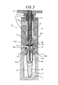
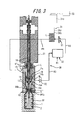
- a blow molding apparatus has a mold 1 for blow molding.
- the cavity 2 of the mold 1 has a bowl shape and opens upward on the upper surface of the mold 1.
- the mold 1 can be opened left and right, and the molded product can be taken out from the mold 1 by opening the mold 1.
- the mold 1 can be fitted with a preform PF that is blow-molded by this blow-molding device to form a casing.
- 1 and 2 show a state in which the preform PF is mounted on the mold 1.
- the preform PF is formed in a bottomed cylindrical shape as a whole by a resin material such as polypropylene (PP), for example, and a cylindrical mouth tube is formed at the upper end of the main body portion PFa having a test tube shape.
- PP polypropylene
- a portion having a shape in which the neck ring PFc is integrally provided at the lower end portion of the mouth tube portion PFb can be used while the portion PFb is integrally provided.
- the preform PF has a main body portion PFa disposed in the cavity 2 of the mold 1 along the axis thereof, and the neck ring PFc is in contact with the upper surface of the mold 1 so that the mouth tube portion PFb is formed of the mold PFb. 1 is protruded to the outside (upward in FIG. 1) and attached to the mold 1.
- a nozzle unit 10 is provided on the upper side of the mold 1 so as to be movable relative to the mold 1 in the vertical direction.
- the nozzle unit 10 has a cylindrical shape as a whole, and includes a filling head portion 11 and a support portion 21 to which the filling head portion 11 is detachably screwed in a cartridge manner.
- the filling head part 11 includes a holding member 12, a blow nozzle 13, and a supply cylinder part 14.
- the holding member 12 is formed in a block shape having a through hole penetrating in the vertical direction at the center thereof, and a cylindrical blow nozzle 13 is mounted inside the through hole.
- the mouth tube portion PFb of the preform PF attached to the mold 1 is disposed inside the through hole, and the blow nozzle 13 is fitted inside the mouth tube portion PFb.
- the neck ring PFc is sandwiched between the lower end of the holding member 12 and the upper surface of the mold 1, and the preform PF is held in a mounting posture perpendicular to the mold 1.
- a space S is defined between the outer peripheral surface of the mouth tube portion PFb of the preform PF attached to the mold 1 and the inner peripheral surface of the holding member 12.
- the supply cylinder portion 14 is configured as a cylindrical member provided with a supply path Fs extending in the vertical direction therein, and is fixed to the upper end of the holding member 12 and the mold 1 together with the holding member 12. It can be moved up and down relative to.
- An introduction port 14a that is continuous with the supply path Fs is provided on the upper end side of the supply cylinder portion 14, and a discharge port 14b that is continuous with the supply path Fs is provided on the lower end side.
- a conical seal surface 14c inclined in a reduced diameter toward the lower side is provided at the lower end of the inner surface forming the supply path Fs of the supply cylinder portion 14, and the supply axis is supplied to the shaft center of the seal surface 14c.
- a supply hole 14 d that opens the path Fs downward and communicates with the blow nozzle 13 is provided.
- the seal body 15 is formed in a short cylindrical shape, and a tapered contact surface 15a is provided on the outer peripheral edge of the lower end surface.
- the contact surface 15a has the same inclination angle as the seal surface 14c and can be in close contact with the seal surface 14c.
- An elongated cylindrical rod-like shaft body 16 is disposed along the axis of the supply path Fs inside the supply path Fs.
- the shaft body 16 penetrates the upper end of the supply cylinder portion 14 in a liquid-tight manner, and supports 21. Thus, it is supported so as to be movable in the vertical direction with respect to the filling head portion 11 and the support portion 21.
- the seal body 15 is coaxially fixed to the lower end of the shaft body 16 and is movable up and down together with the shaft body 16 inside the supply path Fs.
- the contact surface 15 a of the seal body 15 contacts the seal surface 14 c at the lower end of the supply cylinder portion 14, and the supply hole 14 d, that is, the blow nozzle 13 is closed by the seal body 15. .
- the contact surface 15a of the seal body 15 is separated from the seal surface 14c of the supply cylinder portion 14, and the supply hole 14d, that is, the blow nozzle 13 is opened.
- the shaft body 16 is hollow, and an extending rod 17 is slidably mounted on the inside thereof.
- the stretching rod 17 is movable relative to the shaft body 16 in the axial direction, and its lower end protrudes from the lower end of the seal body 15. As shown by a two-dot chain line in FIG. 2, the stretching rod 17 can stretch the preform PF in the longitudinal direction (axial direction) by moving downward.
- a guide body 18 made of polyether ether ketone (PEEK) resin having a short cylindrical shape is fixed to the lower end of the seal body 15 in order to guide the stretching rod 17.
- PEEK polyether ether ketone
- a plunger pump 31 and a liquid circulation part 32 are connected to the nozzle unit 10.
- the plunger pump 31 includes a cylinder 31a and a plunger 31b mounted in the cylinder 31a so as to be movable in the axial direction.
- the supply cylinder portion is connected via the pipe P1.
- the pressurized liquid L can be supplied from the 14 introduction ports 14a into the supply path Fs.
- the plunger pump 31 is a servo plunger type having an electric motor 31c as a drive source, and the plunger 31b is driven by the electric motor 31c so as to operate in the axial direction in the cylinder 31a. It has become.
- a control device 33 as a control unit is connected to the electric motor 31c, and the operation of the electric motor 31c is controlled by the control device 33.
- the controller 33 can operate the electric motor 31c and change the rotation speed (the number of rotations per unit time) and the torque of the electric motor 31c to various values. That is, the control device 33 can drive the plunger 31b with an arbitrary operating speed and operating force by controlling the rotational speed and torque of the electric motor 31c.
- the control device 33 can be configured to perform a control operation in conjunction with a control system for controlling the operation of the sealing body 15 and the stretching rod 17 of the blow molding device, or the control system 33 It can also be configured as part.
- the liquid circulating unit 32 adjusts the liquid L to a predetermined temperature while replenishing the liquid L from the pipe R1, supplies the liquid L to the plunger pump 31 through the pipe R2, and also adjusts the liquid L to the predetermined temperature.
- the supply path Fs that is, the liquid L is configured as follows: supply path Fs ⁇ discharge port 14b ⁇ pipe R3 ⁇ liquid circulation unit 32 ⁇ pipe R2 ⁇ plunger pump 31 ⁇ pipe P1 ⁇ introduction port 14a ⁇ supply path Fs.
- the circulation path CR can be circulated.
- the circulation path CR is provided with two electromagnetic valves V1 and V2, and a predetermined flow path is opened and closed by the corresponding valves V1 and V2 corresponding to each process of blow molding.
- connection cylinder part 14 is provided with a connection port 14e communicating with the blow nozzle 13 through a supply hole 14d.
- a deaeration mechanism that sucks out air in the preform PF prior to blow molding, or low pressure air is instantaneously supplied into the connection port 14e and remains in the connection port 14e.
- a mechanism for discharging the liquid can be connected.
- the seal body 15 moves upward and the supply hole 14d, that is, the blow nozzle 13 is opened in a state where the plunger pump 31 is operated, the liquid pressurized from the plunger pump 31 to the blow nozzle 13 via the supply path Fs. L is supplied.
- the preform PF can be blow-molded into a shape along the cavity 2 of the mold 1.
- the control device 33 when the seal body 15 moves upward and starts its opening operation, the control device 33 operates the electric motor 31c at a predetermined rotational speed and torque so that the plunger pump 31 performs the preform. Supply of pressurized liquid L into the PF is started.
- control device 33 sets the rotational speed and torque of the electric motor 31c to lower values than before the lapse of the predetermined time after the lapse of a predetermined time since the supply of the pressurized liquid L into the preform PF is started. change. That is, the control device 33 controls the electric motor 31c to operate at a constant rotational speed and torque until a predetermined time elapses after the supply of the pressurized liquid L into the preform PF is started. Then, after a predetermined time has elapsed since the supply of the pressurized liquid L into the preform PF was started, the rotational speed and torque of the electric motor 31c are changed to lower values than before.
- control device 33 changes the rotational speed and torque of the electric motor 31c to values lower than before after a predetermined time has elapsed since the supply of the pressurized liquid L into the preform PF was started.
- the peak pressure of the liquid L supplied into the preform PF is controlled between 3.5 MPa and 5.0 MPa.
- the pressure of the liquid L supplied into the preform PF can be measured by, for example, a pressure gauge provided in the blow nozzle 13 or the supply hole 14d.
- FIG. 3 is a view showing a state where a preform is blow-molded by the blow-molding apparatus shown in FIG. 1
- FIG. 4 is a view showing a state where blow-molding by the blow-molding apparatus shown in FIG. 1 is completed.
- FIG. 5 is a time chart showing the processing procedure of blow molding by the blow molding apparatus shown in FIG.
- the preform PF in which the portion excluding the mouth tube portion PFb is heated to a temperature suitable for blow molding, is mounted on the mold 1 for blow molding with the mouth tube portion PFb protruding upward and clamped. .
- the nozzle unit 10 is lowered (indicated by a three-dot chain line in FIG. 5), and the neck ring PFc is sandwiched between the holding member 12 and the upper surface of the mold 1 to hold the preform PF in the mold 1.
- the supply hole 14d is closed by the seal body 15 and the valves V1 and V2 of the circulation path CR are both opened, and the liquid L is circulated while being adjusted to a predetermined temperature by the liquid circulation section 32. It circulates through the road CR.
- FIG. 1 shows this state.
- the stretching rod 17 is moved downward (indicated by a two-dot chain line in FIG. 5), and the preform PF is moved in the longitudinal direction (axial direction) by the stretching rod 17. Stretch to.
- the valves V1 and V2 are closed to stop the circulation of the liquid L along the circulation path CR, as shown in FIG.
- the seal body 15 is moved upward together with the shaft body 16 to open the supply hole 14d, that is, the blow nozzle 13 (indicated by a one-dot chain line in FIG. 5).
- the operation of the electric motor 31c is started by the control device 33, and the plunger 31b starts to operate (shown by a broken line in FIG. 5).
- the pressurized liquid L fed from the plunger pump 31 is supplied into the preform PF through the supply hole 14d and the blow nozzle 13 (liquid supply step), and blow molding is performed.
- the control device 33 starts supplying a pressurized liquid L into the preform PF for a predetermined time (in the case of FIG. 5, about 0.5 seconds).
- a predetermined time in the case of FIG. 5, about 0.5 seconds.
- the plunger 31b is operated at a constant operating speed and operating force by operating the electric motor 31c at a constant rotational speed and torque.
- the seal body 15 is fully opened before the predetermined time has elapsed.
- control device 33 changes the rotation speed and torque of the electric motor 31c to values lower than before after a predetermined time has elapsed since the supply of the pressurized liquid L into the preform PF was started. This change is performed before the supply of the liquid L into the preform PF is completed.
- the control device 33 reduces the operating speed and operating force of the plunger 31b, and controls the supply pressure P of the liquid L supplied to the preform PF (peak pressure control step). That is, the control device 33 reduces the operating speed and the operating force of the plunger 31b after a predetermined time has elapsed since the start of the supply of the pressurized liquid L into the preform PF, thereby reducing the liquid L.
- the operating speed and operating force of the plunger pump 31, that is, the plunger 31 b are increased in the initial stage of supplying the liquid L, so that the inside of the preform PF is increased. It is possible to increase the shapeability of the preform PF by increasing the pressure of the liquid L to be supplied to the specified supply pressure P in a short time. Further, after a predetermined time has elapsed since the supply of the pressurized liquid L is started, the operating speed and operating force of the plunger 31b are reduced, and the liquid L is supplied into the preform PF at a supply pressure P lower than the initial supply.
- the pressure of the liquid L is accelerated, and the water hammer (water hammer action) is suppressed during the supply of the pressurized liquid L into the preform PF.
- the peak pressure of the liquid L supplied into the preform PF can be controlled between 3.5 MPa and 5.0 MPa.
- the liquid L is supplied into the preform PF at a supply pressure P lower than the initial supply, and a prescribed amount of the liquid L is supplied to the preform PF. Then, the operation of the plunger 31b is stopped, and this state is maintained until a predetermined holding time elapses with the seal body 15 being opened.
- the stretching rod 17 moves upward and is taken out of the preform PF, and the liquid L corresponding to the reduced amount of the stretching rod 17 taken out and removed is preformed by the operation of the plunger pump 31. Supplied in the PF.
- the filling amount of the liquid L can be adjusted by performing a suck-back process in which the plunger 31b of the plunger pump 31 is actuated in the return direction to suck the liquid L from the supply hole 14d.
- the plunger 31b is returned and the suck-back process is started 4.4 seconds after the blow molding processing procedure is started.
- the preform PF is expanded in the lateral direction (radial direction) in an expanded state by the pressure of the liquid L supplied from the plunger pump 31, and has a shape along the cavity 2 of the mold 1. It can be a skeleton.
- the seal body 15 When blow molding is completed, next, as shown in FIG. 4, the seal body 15 is lowered together with the shaft body 16 to close the supply hole 14d, that is, the blow nozzle 13, and the valves V1 and V2 are opened to circulate the liquid L again. Circulate along the road CR.
- the sealing body 15 is closed 5.5 seconds after the start of the processing procedure after the suck back process is completed. Further, after 6.4 seconds from the start of the processing procedure, the nozzle unit 10 moves up, and the mouth tube portion of the casing formed by blow-molding the preform PF is removed from the blow nozzle 13. Then, the mold 1 is opened and the casing filled with the liquid L is taken out, and the mouth tube portion is sealed with a cap or the like to complete the product containing the liquid L as the content liquid in the casing (bottle). To do.
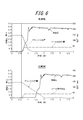
- FIG. 6 is a diagram comparing the time chart of the blow molding apparatus shown in FIG. 1 with the time chart of the blow molding apparatus of the comparative example.
- the operating speed and operating force of the plunger 31 b are changed from the start of the supply of the pressurized liquid L to the preform PF until the completion of the supply of the liquid L.
- the operating speed of the plunger 31 b is set to about one third of the operating speed of the blow molding apparatus (blow molding method) of the present invention shown in the upper time chart of FIG. 6. Therefore, the cycle of blow molding becomes long, and the manufacturing cost of the product is increased.
- the operation speed and the operation force of the plunger 31b are reduced after a predetermined time since the supply of the liquid L pressurized to the preform PF is started, and the initial supply is performed.
- the operating speed and operating force of the plunger 31b at the initial supply of the liquid L pressurized to the preform PF are increased, and the preform PF is supplied.
- the liquid supplied into the preform PF can be controlled between 3.5 MPa and 5.0 MPa. Accordingly, the preform PF can be blow-molded into a predetermined shape with high precision and stability by shortening the blow molding cycle and reducing the manufacturing cost of the product, and improving the shapeability of the preform PF. .
- the peak pressure of the liquid L is excessively increased by the water hammer phenomenon by changing the operating speed and operating force of the plunger pump 31 during the supply of the pressurized liquid L into the preform PF.
- the peak pressure of the liquid L supplied into the preform PF can be controlled between 3.5 MPa and 5.0 MPa. Therefore, while increasing the pressure of the liquid L supplied to the preform PF, the water hammer phenomenon due to the reaction can be suppressed, and the formability of the preform PF and the stability of blow molding can be improved.
- the present invention by suppressing the water hammer phenomenon as described above, the peak pressure of the liquid L is suppressed within the range of the pressure resistance of the blow molding device, and the nozzle unit 10 and the mold 1 are moved during the blow molding. It is possible to prevent a liquid leak or the like from occurring due to a gap therebetween.
- FIG. 7 is a modification of the blow molding process procedure shown in FIG. 5 and is a time chart when the holding time is shortened.
- the shaping of the preform is performed by increasing the pressure of the liquid L supplied to the preform PF while suppressing the occurrence of the water hammer phenomenon during the supply of the pressurized liquid L into the preform PF. Therefore, the retention time can be shortened as compared with the case shown in the blow molding time chart shown in FIG. Thereby, the cycle of blow molding can be further shortened, and the manufacturing cost of the product can be further increased.
- blow molding apparatus blow molding method
- the time from when the supply of pressurized liquid to the preform is started until the rotation speed and torque (plunger torque) of the servo motor (electric motor) are changed (time until the variable) is made different from each other.
- Three examples 1 to 3 were prepared. In the first embodiment, the time is set to 0.228 seconds, in the second embodiment, the time is set to 0.222 seconds, and in the third embodiment, the time is set to 0.241 seconds.
- the speed of the servo motor from the start of the supply of the pressurized liquid to the preform to the lapse of a predetermined time is the same at 3000 rpm, and the plunger torque is the same at 45 Nm.
- the speed of the servo motor after the lapse of a predetermined time from the start of supplying the liquid pressurized to the preform is the same at 1250 rpm, and the plunger torque is the same at 36.9 Nm. It is.
- Comparative Examples 1 to 5 were prepared as comparative examples for Examples 1 to 3. Comparative Examples 1 to 3 are shorter than Examples 1 to 3 in which the time from the start of supplying pressurized liquid to the preform until the servo motor rotation speed and plunger torque are changed is set shorter. In Comparative Example 1, the time is set to 0.205 seconds, in Comparative Example 2, the time is set to 0.180 seconds, and in Comparative Example 3, the time is set to 0.170 seconds.
- Comparative Examples 4 and 5 the speed of the servo motor and the plunger torque are kept constant from the start of the supply of the pressurized liquid to the preform until the completion of the supply of the liquid. .
- the servo motor speed is 1250 rpm and the servo motor torque (plunger torque) is 36.9 Nm.
- the servo motor speed is 3000 rpm and the servo motor torque (plunger torque). ) Is 45 Nm.
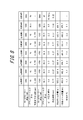
- a preform was blow-molded under the conditions of Examples 1 to 3 and Comparative Examples 1 to 5, and the peak pressure (MPa) of the liquid at that time, the bottle capacity (ml) immediately after blow molding, and 1 day after the blow molding The bottle capacity (ml) and the shrinkage (%) of the bottle capacity immediately after blow molding and one day later were compared.
- the comparison result is shown in FIG.
- Comparative Example 4 the peak pressure of the liquid at the time of blow molding is 4.0 MPa, which is the same as in Examples 1 to 3, but the pressurization time of the liquid is 1.0 second, which is about four times that of Examples 1 to 3. It becomes long. Therefore, in Comparative Example 4, compared with Examples 1 to 3, the bottle capacity immediately after blow molding is significantly reduced. As a result, in Comparative Example 4, the shrinkage rate of the bottle capacity is significantly increased to 6.1% compared to 2.3% in Examples 1 to 3. From this, it can be seen that, in Comparative Example 4, since the pressurization of the liquid is slow, the formability of the preform at the initial stage of pressurization cannot be sufficiently improved, and the blow molding of the preform is unstable. .
- Comparative Example 5 the speed of the servo motor and the plunger torque are increased compared to Comparative Example 4, so that the liquid pressurization time is 0.25 seconds, which is the same as in Examples 1 to 3.
- the peak pressure of the liquid at the time of blow molding becomes as high as 10.0 MPa or more. Therefore, in Comparative Example 5, the mold is mechanically opened at the time of blow molding, or the preform is damaged, so that blow molding cannot be completed, and the bottle capacity immediately after (bottle capacity immediately after blow molding), The bottle capacity after 1 day (bottle capacity after 1 day from blow molding) and the shrinkage rate could not be obtained.
- the control device 33 determines the operating speed and operating force of the plunger pump 31 (plunger 31b) after a predetermined time has elapsed since the start of supply of the pressurized liquid L into the preform PF.
- the value is changed to a value lower than that before the lapse of time.
- the value is not limited to this, and the operating speed and operating force of the plunger pump 31 are changed during the supply of the pressurized liquid L into the preform PF.
- the peak pressure of the liquid L supplied into the preform PF can be controlled between 3.5 MPa and 5.0 MPa, for example, the plan during the supply of the pressurized liquid L into the preform PF
- the operating speed and operating force of the jar pump 31 can be changed in multiple stages or continuously and gradually. It is also possible to change the fine actuation force.
- the plunger pump 31 is made into the servo plunger type with which the plunger 31b is driven by the electric motor 31c, it is not restricted to this,
- the operating speed and operating force of the plunger 31b are arbitrary. As long as it can be changed to the above, it can be configured to be driven by another drive mechanism such as a hydraulic cylinder or an air cylinder.
- the liquid L pressurized by opening the sealing body 15 in the middle of the longitudinal stretching by the stretching rod 17 is supplied into the preform PF, but the longitudinal stretching by the stretching rod 17 is started.
- the supply of the pressurized liquid L into the preform PF is started, or the supply of the pressurized liquid L into the preform PF is started after the longitudinal stretching by the stretching rod 17 is completed. You can also.
- the preform PF is expanded in both the longitudinal direction (axial direction) and the lateral direction (radial direction) in an expanded state only by the pressure of the liquid L supplied from the plunger pump 31 without using the stretching rod 17. It is also possible to adopt a configuration in which the casing has a shape along the cavity 2 of the mold 1.
- the preform PF a preform having a main body portion PFa and a mouth tube portion PFb but not having a neck ring PFc can be used.
- the material of the preform PF is not limited to polypropylene, but may be other resin materials.
Landscapes
- Engineering & Computer Science (AREA)
- Manufacturing & Machinery (AREA)
- Mechanical Engineering (AREA)
- Blow-Moulding Or Thermoforming Of Plastics Or The Like (AREA)
Abstract
ブロー成形用の金型(1)に装着された有底筒状のプリフォーム(PF)に加圧した液体(L)を供給してプリフォーム(PF)を金型(1)のキャビティ(2)に沿った形状に成形するブロー成形装置に、プリフォーム(PF)の口筒部(PFb)に嵌合するブローノズル(13)と、ブローノズル(13)を通してプリフォーム(PF)に加圧した液体(L)を供給するプランジャーポンプ(31)と、プリフォーム(PF)内への加圧した液体(L)の供給中に、プランジャーポンプ(31)の作動速度および作動力を変更して、プリフォーム(PF)内に供給される液体(L)のピーク圧を3.5MPa~5.0MPaの間に制御する制御装置(33)と、を設ける。
Description
本発明は、有底筒状のプリフォームを壜体にブロー成形するブロー成形装置およびブロー成形方法に関し、特に、ブロー成形を行うための加圧流体として液体を使用するものに関する。
延伸ポリプロピレン(OPP)製の壜体やポリエチレンテレフタレート(PET)製の壜体(ペットボトル)に代表されるような樹脂製の壜体は、飲料用、食品用、化粧料用等の様々な用途に使用されている。このような壜体は、射出成形等により有底筒状に形成された樹脂製のプリフォームを、延伸効果を発現させることのできる温度にまで加熱し、この状態でブロー成形装置を用いて2軸延伸ブロー成形することで所定の形状に形成されるのが一般的である。
ブロー成形装置としては、プリフォーム内に供給される加圧流体として、加圧エアに替えて加圧した液体を使用するようにしたものが知られている。この場合、液体として飲料、化粧品、薬品等の最終的に製品として壜体に充填される内容液を使用することにより、壜体への内容液の充填工程を省略して、その生産工程やブロー成形装置の構成を簡略化することができる。
例えば特許文献1には、延伸可能な温度にまで加熱されたプリフォームが装着されるブロー成形用の金型と、金型に装着されたプリフォームの口筒部に嵌合するブローノズルと、ブローノズルを通してプリフォームに加圧された液体を供給する加圧液体供給部と、上下方向に移動自在の延伸ロッドとを備え、延伸ロッドによりプリフォームを縦方向(軸方向)に延伸させつつ、プリフォーム内に加圧された液体を供給してプリフォームを横方向(径方向)に延伸させて、プリフォームを金型のキャビティに沿った形状の壜体に成形するようにしたブロー成形装置が記載されている。
プリフォーム内に供給される加圧流体として最終的に製品として壜体に充填される内容液を用いるようにしたブロー成形装置では、内容液を加圧供給するための加圧液体供給部として、電動モータにより駆動されるサーボプランジャータイプのプランジャーポンプを用いることができる。加圧液体供給部としてプランジャーポンプを用いることにより、製品となる壜体へ精度良く一定量の内容液を充填することができる。
しかしながら、プリフォームの賦形性を高めるためには、プリフォームに供給する液体を規定の圧力にまで短時間で昇圧する必要があるので、プランジャーポンプの作動速度は大きくなり、その反動で、プリフォーム内への加圧した液体の供給中にウォーターハンマー現象(水撃作用)が生じるおそれがある。ウォーターハンマー現象が生じると、プリフォーム内に供給される液体のピーク圧力が、例えば10MPa程度と、規定圧力よりも大幅に高くなって、プリフォームの賦形性やブロー成形の安定性を低下させる要因となっていた。
本発明は、このような課題に鑑みてなされたものであり、その目的は、プリフォームに供給する液体の昇圧を早くしつつ、その反動によるウォーターハンマー現象を抑えて、プリフォームの賦形性とブロー成形の安定性とを高めることができるブロー成形装置およびブロー成形方法を提供することにある。
本発明のブロー成形装置は、ブロー成形用の金型に装着された有底筒状のプリフォームに加圧した液体を供給して該プリフォームを前記金型のキャビティに沿った形状に成形するブロー成形装置であって、前記プリフォームの口筒部に嵌合するブローノズルと、前記ブローノズルを通して前記プリフォームに加圧した液体を供給するプランジャーポンプと、前記プリフォーム内への加圧した液体の供給中に、前記プランジャーポンプの作動速度および作動力を変更して、前記プリフォーム内に供給される液体のピーク圧を3.5MPa~5.0MPaの間に制御する制御部と、を有することを特徴とする。
本発明のブロー成形装置では、前記制御部は、前記プリフォーム内への加圧した液体の供給開始から所定時間経過後に、前記プランジャーポンプの作動速度および作動力を、当該時間の経過前よりも低い値に変更するのが好ましい。
本発明のブロー成形装置では、前記プランジャーポンプは電動モータを駆動源としたサーボプランジャータイプであり、前記制御部は、前記電動モータの回転速度およびトルクを変更することで、前記プランジャーポンプの作動速度および作動力を変更するのが好ましい。
本発明のブロー成形装置では、前記ブローノズルを開閉するシール体を備え、該シール体の開動作が開始されたときに、前記プランジャーポンプから前記プリフォーム内への加圧した液体の供給を開始するのが好ましい。
本発明のブロー成形方法は、ブロー成形用の金型に装着された有底筒状のプリフォームに加圧した液体を供給して該プリフォームを前記金型のキャビティに沿った形状に成形するブロー成形方法であって、プランジャーポンプにより、前記プリフォームの口筒部に嵌合するブローノズルを通して該プリフォームに加圧した液体を供給する液体供給工程と、前記プリフォーム内への加圧した液体の供給中に、前記プランジャーポンプの作動速度および作動力を変更して、前記プリフォーム内に供給される液体のピーク圧を3.5MPa~5.0MPaの間に制御するピーク圧制御工程と、を有することを特徴とする。
本発明のブロー成形方法では、前記ピーク圧制御工程においては、前記プリフォーム内への加圧した液体の供給開始から所定時間経過後に、前記プランジャーポンプの作動速度および作動力を、当該時間の経過前よりも低い値に変更するのが好ましい。
本発明によれば、プリフォーム内への加圧した液体の供給中に、プランジャーポンプの作動速度および作動力を変更することで、ウォーターハンマー現象による液体の圧力の上昇を抑制して、プリフォーム内に供給される液体のピーク圧を3.5MPa~5.0MPaの間に制御するようにしたので、プリフォームに供給する液体の昇圧を早くしつつ、その反動によるウォーターハンマー現象を抑えてプリフォームの賦形性やブロー成形の安定性を高めることができる。
図1、図2に示すように、本発明の一実施の形態であるブロー成形装置は、ブロー成形用の金型1を有している。この金型1のキャビティ2は壜形状となっており、金型1の上面において上方に向けて開口している。詳細は図示しないが、金型1は左右に型開きすることができるようになっており、金型1を開くことで成形後の製品を金型1から取り出すことができる。
金型1には、このブロー成形装置によりブロー成形されて壜体を形成するプリフォームPFを装着することができる。図1、図2においては、金型1にプリフォームPFを装着した状態を示す。図2に示すように、プリフォームPFとしては、例えばポリプロピレン(PP)等の樹脂材料により全体として有底円筒状に形成され、その試験管形状となる本体部PFaの上端に円筒状の口筒部PFbが一体に設けられるとともに、口筒部PFbの下端部にネックリングPFcが一体に設けられた形状のものを用いることができる。このプリフォームPFは、その本体部PFaが金型1のキャビティ2内にその軸心に沿って配置されるとともに、ネックリングPFcが金型1の上面に当接して口筒部PFbが金型1の外部(図1中では上方)に突出した状態となって金型1に装着される。
図1に示すように、金型1の上側には、金型1に対して上下方向に相対移動自在にノズルユニット10が設けられている。このノズルユニット10は全体として筒状で、充填ヘッド部11と、この充填ヘッド部11がカートリッジ式に着脱自在にねじ結合される支持部21とを備えている。
充填ヘッド部11は、保持部材12、ブローノズル13および供給筒部14を備えている。
保持部材12は、その中心に上下方向に貫通する貫通孔を備えたブロック状に形成され、この貫通孔の内側に筒状のブローノズル13が装着されている。ノズルユニット10が下端にまで下げられると、金型1に装着されたプリフォームPFの口筒部PFbが貫通孔の内部に配置されてブローノズル13が当該口筒部PFbの内側に嵌合するとともに、ネックリングPFcが保持部材12の下端と金型1の上面との間に挟み込まれて、プリフォームPFは金型1に対して垂直な装着姿勢に保持される。
なお、金型1に装着されたプリフォームPFの口筒部PFbの外周面と保持部材12の内周面との間にはこれを囲繞する空間Sが区画形成されている。
図2に示すように、供給筒部14は、その内部に上下方向に延びる供給路Fsを備えた円筒状の部材に構成され、保持部材12の上端に固定されて保持部材12とともに金型1に対して上下に相対移動可能となっている。供給筒部14の上端側には供給路Fsに連なる導入ポート14aが設けられ、下端側には供給路Fsに連なる排出ポート14bが設けられている。また、供給筒部14の供給路Fsを形成する内面の下端には、下方に向けて縮径状に傾斜する円錐面状のシール面14cが設けられ、このシール面14cの軸心には供給路Fsを下方に向けて開口させてブローノズル13に連通させる供給孔14dが設けられている。
供給路Fsの内部には供給孔14dつまりブローノズル13を開閉するためのシール体15が配置されている。シール体15は短円柱状に形成され、その下端面の外周縁部にはテーパー状の当接面15aが設けられている。この当接面15aは、シール面14cと同一の傾斜角度を有し、シール面14cと密着することができる。供給路Fsの内部には供給路Fsの軸心に沿って細長い円筒棒状の軸体16が配置されており、この軸体16は供給筒部14の上端を液密に貫通し、支持部21により充填ヘッド部11および支持部21に対して上下方向に移動自在に支持されている。シール体15は、軸体16の下端に同軸に固定され、この軸体16とともに供給路Fsの内部で上下に移動自在となっている。軸体16が下方のストローク端にまで移動するとシール体15の当接面15aが供給筒部14の下端部のシール面14cに当接し、供給孔14dつまりブローノズル13がシール体15により閉じられる。一方、軸体16とともにシール体15が上方に移動すると、シール体15の当接面15aが供給筒部14のシール面14cから離れて、供給孔14dつまりブローノズル13が開かれる。
軸体16は中空となっており、その内側には延伸ロッド17が摺動自在に装着されている。延伸ロッド17は軸体16に対して軸方向に相対移動可能となっており、その下端はシール体15の下端から突出している。図2に二点鎖線で示すように、延伸ロッド17は、下方に向けて移動することにより、プリフォームPFを縦方向(軸方向)に延伸することができる。
なお、シール体15の下端には、延伸ロッド17をガイドするために、短円筒状でポリエーテルエーテルケトン(PEEK)樹脂製のガイド体18が固定されている。
図1に示すように、ノズルユニット10にはプランジャーポンプ31および液体循環部32が接続されている。
プランジャーポンプ31は、シリンダ31aとこのシリンダ31a内に軸方向に沿って移動自在に装着されたプランジャー31bとを備えており、プランジャー31bが作動することにより配管P1を介して供給筒部14の導入ポート14aから供給路Fs内に加圧した液体Lを供給することができる。図示する場合では、プランジャーポンプ31は、駆動源として電動モータ31cを備えたサーボプランジャータイプとなっており、プランジャー31bは電動モータ31cにより駆動されてシリンダ31a内で軸方向に作動するようになっている。
電動モータ31cには制御部としての制御装置33が接続され、この制御装置33により電動モータ31cの作動が制御されるようになっている。制御装置33は、電動モータ31cを作動させるとともに電動モータ31cの回転速度(単位時間当たりの回転数)およびトルクを種々の値に変更することができる。つまり、制御装置33は、電動モータ31cの回転速度およびトルクを制御することにより、プランジャー31bを任意の作動速度および作動力で駆動することができる。また、この制御装置33は、このブロー成形装置のシール体15や延伸ロッド17等の作動を制御するための制御システムと連動して制御動作を行う構成とすることができ、または当該制御システムの一部として構成されることもできる。
液体循環部32は、液体Lを配管R1から新たに補給しながら所定の温度に調整して配管R2を通してプランジャーポンプ31に供給するとともに、液体Lを所定の温度に調整しながらプランジャーポンプ31と供給路Fsとの間を循環させる機能を有する。すなわち、液体Lを必要に応じて、供給路Fs→排出ポート14b→配管R3→液体循環部32→配管R2→プランジャーポンプ31→配管P1→導入ポート14a→供給路Fsと云うように構成される循環路CRを循環させることができる。
循環路CRには2つの電磁式のバルブV1,V2が設けられ、ブロー成形の各工程に対応して所定の流路が対応するバルブV1,V2により開閉される。
供給筒部14には供給孔14dを介してブローノズル13に連通する接続ポート14eが設けられている。この接続ポート14eには、例えば、ブロー成形に先立ってプリフォームPF内の空気を吸い出す脱気機構や、この接続ポート14e内に低圧のエアを瞬間的に供給して当該接続ポート14e内に残った液体を排出する機構等を接続することができる。
プランジャーポンプ31が作動した状態でシール体15が上方に移動して供給孔14dつまりブローノズル13が開かれると、プランジャーポンプ31から供給路Fsを介してブローノズル13に加圧された液体Lが供給される。このように、ブローノズル13を通して加圧された液体LをプリフォームPF内に供給(充填)することで、プリフォームPFを金型1のキャビティ2に沿った形状にブロー成形することができる。
本発明では、制御装置33は、シール体15が上方に移動してその開動作を開始したときに、電動モータ31cを予め定められた回転速度およびトルクで作動させ、プランジャーポンプ31からプリフォームPF内への加圧した液体Lの供給を開始させる。
また、制御装置33は、プリフォームPF内への加圧した液体Lの供給を開始してから所定時間経過後に、電動モータ31cの回転速度およびトルクを、当該時間の経過前よりも低い値に変更する。つまり、制御装置33は、プリフォームPF内への加圧した液体Lの供給を開始してから所定時間が経過するまでは、電動モータ31cを一定の回転速度およびトルクで作動するように制御し、プリフォームPF内への加圧した液体Lの供給を開始してから所定時間経過後に、電動モータ31cの回転速度およびトルクをそれまでよりも低い値に変更する。このように、制御装置33は、プリフォームPF内への加圧した液体Lの供給を開始してから所定時間経過後に、電動モータ31cの回転速度およびトルクをそれまでよりも低い値に変更することで、プリフォームPF内に供給される液体Lのピーク圧を3.5Mpa~5.0MPaの間に制御する。
なお、プリフォームPF内に供給される液体Lの圧力は、例えば、ブローノズル13や供給孔14dに設けた圧力計により計測する構成とすることができる。
図3は図1に示すブロー成形装置によりプリフォームをブロー成形している状態を示す図であり、図4は図1に示すブロー成形装置によるブロー成形が完了した状態を示す図である。また、図5は、図1に示すブロー成形装置によるブロー成形の処理手順を示すタイムチャート図である。
次に、このようなブロー成形装置を用いてプリフォームPFをブロー成形して壜体を形成する処理手順つまり本発明のブロー成形方法について図1~図5を適宜参照しつつ説明する。
まず、口筒部PFbを除く部分をブロー成形に適した温度に加熱したプリフォームPFを、口筒部PFbを上方に突出させた状態でブロー成形用の金型1に装着し、型締めする。
次に、ノズルユニット10を下降させ(図5において三点鎖線で示す)、保持部材12と金型1の上面との間にネックリングPFcを挟み込んでプリフォームPFを金型1に保持させる。このとき、シール体15により供給孔14dが閉じた状態とされるとともに循環路CRのバルブV1、V2がいずれも開状態とされ、液体Lは液体循環部32により所定の温度に調整されながら循環路CRを循環している。図1がこの状態を示す。
次に、図2に二点鎖線で示すように、延伸ロッド17を下方に向けて移動させ(図5において二点鎖線で示す)、この延伸ロッド17によりプリフォームPFを縦方向(軸方向)に延伸する。
そして、延伸ロッド17によるプリフォームPFの縦方向(軸方向)への延伸中に、バルブV1、V2を閉じて循環路CRに沿った液体Lの循環を停止させるとともに、図3に示すように、軸体16とともにシール体15を上方に移動させて供給孔14dつまりブローノズル13を開く(図5において一点鎖線で示す)。また、シール体15が開動作を開始すると、制御装置33により電動モータ31cの作動が開始されてプランジャー31bが作動を開始する(図5において破線で示す)。これにより、プランジャーポンプ31から圧送されてきた加圧された液体Lが、供給孔14dおよびブローノズル13を通してプリフォームPFの内部に供給され(液体供給工程)、ブロー成形が行われる。
このとき、図5から解るように、制御装置33は、プリフォームPF内への加圧した液体Lの供給を開始してから所定時間(図5に示す場合では、約0.5秒)が経過するまでは、電動モータ31cを一定の回転速度およびトルクで作動させることにより、プランジャー31bを一定の作動速度および作動力で作動させる。なお、シール体15は、当該所定時間が経過するよりも前に全開状態となる。
また、制御装置33は、プリフォームPF内への加圧した液体Lの供給を開始してから所定時間経過後に、電動モータ31cの回転速度およびトルクをそれまでよりも低い値に変更する。この変更は、プリフォームPF内への液体Lの供給の完了前に行われる。このような制御により、制御装置33は、プランジャー31bの作動速度および作動力を低減させ、プリフォームPFに供給される液体Lの供給圧Pを制御する(ピーク圧制御工程)。つまり、制御装置33は、プリフォームPF内への加圧した液体Lの供給を開始してから所定時間経過後には、プランジャー31bの作動速度および作動力が低減されることで、液体Lを供給初期よりも低い供給圧PでプリフォームPF内に供給する。プリフォームPF内への加圧した液体Lの供給を開始してから所定時間経過後にプランジャー31bの作動速度および作動力が低減されることは、図5において、当該時間の経過後にプランジャー31bの位置を示す破線の傾斜角度が変化していることで示される。
このように、プリフォームPF内へ加圧した液体Lを供給するにあたり、液体Lの供給初期において、プランジャーポンプ31つまりプランジャー31bの作動速度および作動力を大きくすることで、プリフォームPF内に供給する液体Lを規定の供給圧Pにまで短時間で昇圧して、プリフォームPFの賦形性を高めることができる。また、加圧した液体Lの供給を開始してから所定時間経過後に、プランジャー31bの作動速度および作動力を低減させて、供給初期よりも低い供給圧Pで液体LをプリフォームPF内に供給することにより、プリフォームPFに供給する液体Lの昇圧を早くしつつ、プリフォームPF内への加圧した液体Lの供給中にウォーターハンマー(水撃作用)が生じるのを抑制して、プリフォームPF内に供給される液体Lのピーク圧を、3.5Mpa~5.0MPaの間に制御することができる。
加圧した液体Lの供給を開始してから所定時間経過後に、供給初期よりも低い供給圧Pで液体LがプリフォームPF内に供給され、規定量の液体LがプリフォームPFに供給されると、プランジャー31bの作動が停止し、シール体15が開いたままで所定の保持時間が経過するまでこの状態が保持される。
なお、保持時間中において、延伸ロッド17は上方に向けて移動してプリフォームPFの外部に取り出され、延伸ロッド17が取り出されて減量した分の液体Lがプランジャーポンプ31の作動によりプリフォームPF内に供給される。
また、必要に応じて、プランジャーポンプ31のプランジャー31bを戻り方向に作動させて供給孔14dから液体Lを吸い込むサックバック工程を行ない、液体Lの充填量を調整することができる。図5に示す場合では、ブロー成形の処理手順が開始されて4.4秒後にプランジャー31bが戻り動作されてサックバック工程が開始されている。
このようなブロー成形により、プリフォームPFを、プランジャーポンプ31から供給される液体Lの圧力により横方向(径方向)に膨張状に延伸して、金型1のキャビティ2に沿った形状の壜体とすることができる。
なお、ブロー成形において、液体Lの圧力によりプリフォームPFの口筒部PFbが拡径変形するような場合には、図示しない加圧流路を介して保持部材12と口筒部PFbとの間の空間Sに加圧エアを供給することにより、このような拡径変形を効果的に抑制することができる。
ブロー成形が完了すると、次に、図4に示すように、軸体16とともにシール体15を下降させて供給孔14dつまりブローノズル13を閉じ、バルブV1、V2を開状態として液体Lを再び循環路CRに沿って循環させる。図5に示す場合では、サックバック工程が終了した処理手順開始5.5秒後にシール体15が閉じられている。また、処理手順開始6.4秒後にはノズルユニット10が上昇し、プリフォームPFをブロー成形して形成された壜体の口筒部がブローノズル13から取り外される。そして、金型1が型開きされて液体Lが充填された壜体が取り出され、その口筒部がキャップ等でシールされて液体Lを内容液として壜体(ボトル)に収容した製品が完成する。
図6は図1に示すブロー成形装置のタイムチャート図と比較例のブロー成形装置のタイムチャート図とを比較して示す図である。
図6の下側のタイムチャート図に示されるように、プリフォームPFに加圧した液体Lの供給を開始してからその液体Lの供給の完了まで、プランジャー31bの作動速度および作動力を一定としてプリフォームPFに加圧した液体Lを供給するようにした比較例のブロー成形装置(ブロー成形方法)では、ウォーターハンマーによる液体Lの供給圧Pのピーク圧の過度の上昇を抑えるために、図6の上側のタイムチャート図に示される本発明のブロー成形装置(ブロー成形方法)の場合よりも、プランジャー31bの作動速度を約3分の1の作動速度にまで遅くされている。そのため、ブロー成形のサイクルが長くなり、製品の製造コストが高められることになる。
これに対して本発明では、上記のように、プリフォームPFに加圧した液体Lの供給を開始してから所定時間経過後に、プランジャー31bの作動速度および作動力を低減させて、供給初期よりも低い供給圧Pで液体LをプリフォームPF内に供給することにより、プリフォームPFに加圧した液体Lの供給初期におけるプランジャー31bの作動速度および作動力を高くしてプリフォームPFに供給する液体Lの昇圧を早くしつつ、プリフォームPF内への加圧した液体Lの供給中にウォーターハンマー(水撃作用)が生じるのを抑制して、プリフォームPF内に供給される液体Lのピーク圧を、3.5Mpa~5.0MPaの間に制御することができる。これにより、ブロー成形のサイクルを短くして、製品の製造コストを低減させつつ、プリフォームPFの賦形性を高めて精度良く安定して所定の形状にプリフォームPFをブロー成形することができる。
また、本発明では、プリフォームPF内への加圧した液体Lの供給中に、プランジャーポンプ31の作動速度および作動力を変更することで、ウォーターハンマー現象により液体Lのピーク圧が過度に上昇するのを抑制して、プリフォームPF内に供給される液体Lのピーク圧を3.5MPa~5.0MPaの間に制御することができる。したがって、プリフォームPFに供給する液体Lの昇圧を早くしつつ、その反動によるウォーターハンマー現象を抑えてプリフォームPFの賦形性やブロー成形の安定性を高めることができる。
さらに、本発明では、上記のようにウォーターハンマー現象を抑制することにより、液体Lのピーク圧をブロー成形装置の耐圧の範囲内に抑えて、ブロー成形中にノズルユニット10と金型1との間に隙間が生じて液漏れ等が発生することを防止することができる。
図7は図5に示すブロー成形の処理手順の変形例であって保持時間を短縮した場合のタイムチャート図である。
本発明では、プリフォームPF内への加圧した液体Lの供給中にウォーターハンマー現象が生じるのを抑制しつつ、プリフォームPFに供給する液体Lの昇圧を早くすることでプリフォームの賦形性を高めることができるので、図5に示すブロー成形のタイムチャート図に示す場合に比べて、保持時間を短縮することもできる。これにより、ブロー成形のサイクルをさらに短くして、製品の製造コストをさらに高めることができる。
以下に、本発明のブロー成形装置(ブロー成形方法)の実施例について説明する。なお、本発明は以下に記載の実施例の内容に限定されるものではない。
実施例として、プリフォームに加圧した液体の供給を開始してからサーボモータ(電動モータ)の回転速度およびトルク(プランジャートルク)を変更するまでの時間(可変までの時間)を互いに相違させた3つの実施例1~3を用意した。実施例1では当該時間は0.228秒に設定され、実施例2では当該時間は0.222秒に設定され、実施例3では当該時間は0.241秒に設定されている。
全ての実施例1~3において、プリフォームに加圧した液体の供給を開始してから所定時間経過までのサーボモータの速度は3000rpmで同一であり、プランジャートルクも45Nmで同一である。また、全ての実施例1~3において、プリフォームに加圧した液体の供給を開始してから所定時間経過後におけるサーボモータの速度は1250rpmで同一であり、プランジャートルクも36.9Nmで同一である。
実施例1~3に対する比較例として、比較例1~5を用意した。比較例1~3は、実施例1~3に対して、プリフォームに加圧した液体の供給を開始してからサーボモータの回転速度およびプランジャートルクを変更するまでの時間を短く設定したものであり、比較例1では当該時間は0.205秒に設定され、比較例2では当該時間は0.180秒に設定され、比較例3では当該時間は0.170秒に設定されている。それ以外の条件、つまりプリフォームに加圧した液体の供給を開始してから所定時間経過までのサーボモータの速度とプランジャートルク、プリフォームに加圧した液体の供給を開始してから所定時間経過後におけるサーボモータの速度とプランジャートルク、および、液体の昇圧時間は全て実施例1~3の場合と同一である。
一方、比較例4、5は、プリフォームに加圧した液体の供給を開始してからその液体の供給の完了まで、サーボモータの速度とプランジャートルクを変更させずに一定にしたものである。比較例4では、サーボモータの速度は1250rpm、サーボモータのトルク(プランジャートルク)は36.9Nmとされており、比較例5では、サーボモータの速度は3000rpm、サーボモータのトルク(プランジャートルク)は45Nmとされている。
これらの実施例1~3および比較例1~5の条件でプリフォームをブロー成形し、そのときの液体のピーク圧力(MPa)、ブロー成形直後のボトル容量(ml)、ブロー成形から1日経過後のボトル容量(ml)およびブロー成形直後と1日後でのボトル容量の収縮率(%)を比較した。その比較結果を図8に示す。
図8に示す比較結果から明らかなように、実施例1~3の条件でプリフォームのブロー成形を行った場合は、液体のピーク圧力を3.5MPa~5.0MPaと過度に高くすることなく、0.27秒という短い昇圧時間で液体の供給圧を適度な圧力にまで高めてプリフォームのブロー成形を迅速に行うことができる。したがって、実施例1~3では、ブロー成形のサイクルを短くして、製品の製造コストを低減させることが可能であることが解る。
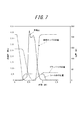
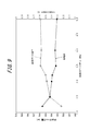
また、図8に示す比較結果から明らかなように、実施例1~3の条件でプリフォームのブロー成形を行った場合は、何れの場合でも、ブロー成形直後のボトル容量に対するブロー成形から1日経過後のボトル容量への収縮率は2.3%と小さくなっている。つまり、図9に示すように、ブロー成形に際してプリフォームに供給される液体のピーク圧力が3.5MPa~5.0MPaの範囲では、それ以下のピーク圧力の範囲に比べてブロー成形直後におけるボトル容量が大きくなり、これによりブロー成形直後のボトル容量に対するブロー成形から1日経過後のボトル容量への収縮率は2.3%と小さくなっている。このように、実施例1~3では、ブロー成形時における液体のピーク圧力を3.5MPa~5.0MPaの範囲に制御することにより、液体の昇圧の初期段階におけるプリフォームの賦形性を高めて、プリフォームを安定して所定形状にブロー成形できていることが解る。
これに対して、比較例1~3では、プリフォームに加圧した液体の供給を開始してからサーボモータの回転速度およびプランジャートルクを変更するまでの時間を実施例1~3よりも短くしたので、ブロー成形時における液体のピーク圧力は2.2MPa~3.0MPaと実施例1~3に比較して小さくなっている。その結果、比較例1~3では、その収縮率は2.4%~2.6%と、実施例1~3に比べて大きくなっているのが解る。図9に示すように、比較例1~3のように2.2MPa~3.0MPaのピーク圧力の範囲では、それ以上のピーク圧力の場合に比べてブロー成形直後におけるボトル容量が小さくなる。このことから、比較例1~3では、液体の昇圧の初期段階におけるプリフォームの賦形性が十分に高められず、プリフォームのブロー成形が不安定となっていることが解る。
一方、比較例4では、ブロー成形時における液体のピーク圧力は4.0MPaと実施例1~3と同等となるが、液体の昇圧時間は1.0秒と実施例1~3の4倍程度に長くなる。そのため、比較例4では、実施例1~3と比較して、ブロー成形直後におけるボトル容量が大幅に小さくなる。これにより、比較例4では、ボトル容量の収縮率も実施例1~3の2.3%に対して6.1%と大幅に大きくなる。このことから、比較例4では、液体の昇圧が遅いために、昇圧の初期段階におけるプリフォームの賦形性が十分に高められず、プリフォームのブロー成形が不安定となっていることが解る。
また、比較例5では、比較例4に比べてサーボモータの速度およびプランジャートルクが高められていることから、液体の昇圧時間が0.25秒と、実施例1~3の場合と同等になるが、ブロー成形時における液体のピーク圧力は10.0MPa以上と高くなる。そのため、比較例5では、ブロー成形時に金型が機械的に開き、またはプリフォームが破損するなどして、ブロー成形を完了することができず、直後ボトル容量(ブロー成形直後のボトル容量)、1日後ボトル容量(ブロー成形から1日経過後のボトル容量)および収縮率を得ることができなかった。このことから、比較例5のように、プリフォームに加圧した液体の供給を開始してからその液体の供給の完了まで、サーボモータの速度とプランジャートルクを変更させずに一定にしつつ、当該サーボモータの速度とプランジャートルクを高く設定して液体の昇圧時間を短くしようとすると、ウォーターハンマー現象により液体のピーク圧力が過度に高くなって、安定してプリフォームのブロー成形を行うことができないことが解る。
本発明は前記実施の形態に限定されるものではなく、その要旨を逸脱しない範囲で種々変更可能であることはいうまでもない。
例えば、前記実施の形態では、制御装置33は、プリフォームPF内への加圧した液体Lの供給開始から所定時間経過後に、プランジャーポンプ31(プランジャー31b)の作動速度および作動力を、当該時間の経過前よりも低い値に変更するようにしているが、これに限らず、プリフォームPF内への加圧した液体Lの供給中にプランジャーポンプ31の作動速度および作動力を変更してプリフォームPF内に供給される液体Lのピーク圧を3.5MPa~5.0MPaの間に制御することができれば、例えば、プリフォームPF内への加圧した液体Lの供給中にプランジャーポンプ31の作動速度および作動力を多段階に変化させたり、連続的に徐々に変化させたりするなど、種々のパターンでプランジャーポンプ31の作動速度および作動力を変更することもできる。
また、前記実施の形態では、プランジャーポンプ31はプランジャー31bが電動モータ31cにより駆動されるサーボプランジャータイプとされているが、これに限らず、プランジャー31bの作動速度および作動力を任意に変更可能なものであれば、例えば油圧シリンダやエアシリンダ等の他の駆動機構で駆動される構成のものとすることもできる。
さらに、前記実施の形態では、液体Lを循環路CRで循環させる構成とされているが、これに限らず、プランジャーポンプ31からブローノズル13を通してプリフォームPF内に加圧された液体Lを供給することができる構成であれば、液体Lを循環させない構成とすることもできる。
さらに、前記実施の形態では、延伸ロッド17による縦延伸の途中でシール体15を開いて加圧した液体LをプリフォームPF内に供給するようにしているが、延伸ロッド17による縦延伸の開始とともに加圧した液体LのプリフォームPF内への供給を開始し、または延伸ロッド17による縦延伸が完了してから加圧した液体LのプリフォームPF内への供給を開始するようにすることもできる。
なお、延伸ロッド17を用いることなく、プランジャーポンプ31から供給される液体Lの圧力のみで、プリフォームPFを縦方向(軸方向)と横方向(径方向)の両方に膨張状に延伸させて金型1のキャビティ2に沿った形状の壜体とする構成とすることもできる。
さらに、プリフォームPFとして、本体部PFaと口筒部PFbとを有するがネックリングPFcを備えない形状のものを用いることもできる。また、プリフォームPFの材質はポリプロピレンに限らず、他の樹脂材料とすることもできる。
1 金型
2 キャビティ
10 ノズルユニット
11 充填ヘッド部
12 保持部材
13 ブローノズル
14 供給筒部
14a 導入ポート
14b 排出ポート
14c シール面
14d 供給孔
14e 接続ポート
15 シール体
15a 当接面
16 軸体
17 延伸ロッド
18 ガイド体
21 支持部
31 プランジャーポンプ
31a シリンダ
31b プランジャー
31c 電動モータ
32 液体循環部
33 制御装置(制御部)
PF プリフォーム
PFa 本体部
PFb 口筒部
PFc ネックリング
S 空間
Fs 供給路
P1 配管
L 液体
R1 配管
R2 配管
R3 配管
CR 循環路
V1,V2 バルブ
Claims (7)
- ブロー成形用の金型に装着された有底筒状のプリフォームに加圧した液体を供給して該プリフォームを前記金型のキャビティに沿った形状に成形するブロー成形装置であって、
前記プリフォームの口筒部に嵌合するブローノズルと、
前記ブローノズルを通して前記プリフォームに加圧した液体を供給するプランジャーポンプと、
前記プリフォーム内への加圧した液体の供給中に、前記プランジャーポンプの作動速度および作動力を変更して、前記プリフォーム内に供給される液体のピーク圧を3.5MPa~5.0MPaの間に制御する制御部と、を有することを特徴とするブロー成形装置。 - 前記制御部は、前記プリフォーム内への加圧した液体の供給開始から所定時間経過後に、前記プランジャーポンプの作動速度および作動力を、当該時間の経過前よりも低い値に変更する、請求項1に記載のブロー成形装置。
- 前記プランジャーポンプは電動モータを駆動源としたサーボプランジャータイプであり、前記制御部は、前記電動モータの回転速度およびトルクを変更することで、前記プランジャーポンプの作動速度および作動力を変更する、請求項1または2に記載のブロー成形装置。
- 前記ブローノズルを開閉するシール体を備え、該シール体の開動作が開始されたときに、前記プランジャーポンプから前記プリフォーム内への加圧した液体の供給を開始する、請求項1または2に記載のブロー成形装置。
- 前記ブローノズルを開閉するシール体を備え、該シール体の開動作が開始されたときに、前記プランジャーポンプから前記プリフォーム内への加圧した液体の供給を開始する、請求項3に記載のブロー成形装置。
- ブロー成形用の金型に装着された有底筒状のプリフォームに加圧した液体を供給して該プリフォームを前記金型のキャビティに沿った形状に成形するブロー成形方法であって、
プランジャーポンプにより、前記プリフォームの口筒部に嵌合するブローノズルを通して該プリフォームに加圧した液体を供給する液体供給工程と、
前記プリフォーム内への加圧した液体の供給中に、前記プランジャーポンプの作動速度および作動力を変更して、前記プリフォーム内に供給される液体のピーク圧を3.5MPa~5.0MPaの間に制御するピーク圧制御工程と、を有することを特徴とするブロー成形方法。 - 前記ピーク圧制御工程においては、前記プリフォーム内への加圧した液体の供給開始から所定時間経過後に、前記プランジャーポンプの作動速度および作動力を、当該時間の経過前よりも低い値に変更する、請求項6に記載のブロー成形方法。
Priority Applications (3)
| Application Number | Priority Date | Filing Date | Title |
|---|---|---|---|
| US15/115,847 US10456973B2 (en) | 2014-01-30 | 2014-11-17 | Blow molding apparatus and blow molding method |
| EP14881196.1A EP3100844B1 (en) | 2014-01-30 | 2014-11-17 | Blow molding apparatus and blow molding method |
| CN201480074588.3A CN105939832B (zh) | 2014-01-30 | 2014-11-17 | 吹塑成形装置及吹塑成形方法 |
Applications Claiming Priority (2)
| Application Number | Priority Date | Filing Date | Title |
|---|---|---|---|
| JP2014015775A JP6230926B2 (ja) | 2014-01-30 | 2014-01-30 | ブロー成形装置およびブロー成形方法 |
| JP2014-015775 | 2014-01-30 |
Publications (1)
| Publication Number | Publication Date |
|---|---|
| WO2015114705A1 true WO2015114705A1 (ja) | 2015-08-06 |
Family
ID=53756329
Family Applications (1)
| Application Number | Title | Priority Date | Filing Date |
|---|---|---|---|
| PCT/JP2014/005759 Ceased WO2015114705A1 (ja) | 2014-01-30 | 2014-11-17 | ブロー成形装置およびブロー成形方法 |
Country Status (5)
| Country | Link |
|---|---|
| US (1) | US10456973B2 (ja) |
| EP (1) | EP3100844B1 (ja) |
| JP (1) | JP6230926B2 (ja) |
| CN (1) | CN105939832B (ja) |
| WO (1) | WO2015114705A1 (ja) |
Cited By (3)
| Publication number | Priority date | Publication date | Assignee | Title |
|---|---|---|---|---|
| WO2017087523A1 (en) * | 2015-11-16 | 2017-05-26 | Discma Ag | Method of forming a container using a liquid |
| WO2018025494A1 (ja) * | 2016-08-03 | 2018-02-08 | 株式会社吉野工業所 | 液体ブロー成形方法 |
| JP2018034447A (ja) * | 2016-08-31 | 2018-03-08 | 株式会社吉野工業所 | 液体ブロー成形方法 |
Families Citing this family (7)
| Publication number | Priority date | Publication date | Assignee | Title |
|---|---|---|---|---|
| JP6450641B2 (ja) * | 2015-04-30 | 2019-01-09 | 株式会社吉野工業所 | 液体ブロー成形装置および液体ブロー成形方法 |
| JP6605312B2 (ja) * | 2015-11-27 | 2019-11-13 | 株式会社吉野工業所 | 液体ブロー成形方法 |
| JP6685705B2 (ja) * | 2015-11-27 | 2020-04-22 | 株式会社吉野工業所 | 液体ブロー成形方法及び液体ブロー成形装置 |
| JP6629647B2 (ja) | 2016-03-11 | 2020-01-15 | 株式会社吉野工業所 | 液体ブロー成形装置及び液体ブロー成形方法 |
| JP6594823B2 (ja) | 2016-04-28 | 2019-10-23 | 株式会社吉野工業所 | 液体ブロー成形方法 |
| JP6864570B2 (ja) | 2017-04-27 | 2021-04-28 | 株式会社吉野工業所 | 液体入り容器の製造方法 |
| DE102024112652A1 (de) * | 2024-05-06 | 2025-11-06 | Khs Gmbh | Verfahren zum Erfassen des Betriebsverhaltens einer Behälterbehandlungsanlage |
Citations (3)
| Publication number | Priority date | Publication date | Assignee | Title |
|---|---|---|---|---|
| JP2013208834A (ja) | 2012-03-30 | 2013-10-10 | Yoshino Kogyosho Co Ltd | ブロー成形装置及び合成樹脂製容器の製造方法 |
| JP2013541448A (ja) * | 2010-10-18 | 2013-11-14 | アムコー リミテッド | 液圧又は水圧ブロー成型 |
| JP2014008636A (ja) * | 2012-06-28 | 2014-01-20 | Yoshino Kogyosho Co Ltd | 容器内部の陽圧化方法及び充填容器 |
Family Cites Families (4)
| Publication number | Priority date | Publication date | Assignee | Title |
|---|---|---|---|---|
| JP2006142369A (ja) * | 2004-11-24 | 2006-06-08 | Ykk Corp | 電動式射出ユニット及び同ユニットを備えたダイキャストマシンと電動式射出方法 |
| US7914726B2 (en) * | 2006-04-13 | 2011-03-29 | Amcor Limited | Liquid or hydraulic blow molding |
| US9044887B2 (en) * | 2011-05-27 | 2015-06-02 | Discma Ag | Method of forming a container |
| US8740609B2 (en) * | 2011-06-09 | 2014-06-03 | Amcor Limited | CSD cooling and pressurization to keep CO2 in solution during forming |
-
2014
- 2014-01-30 JP JP2014015775A patent/JP6230926B2/ja active Active
- 2014-11-17 CN CN201480074588.3A patent/CN105939832B/zh active Active
- 2014-11-17 WO PCT/JP2014/005759 patent/WO2015114705A1/ja not_active Ceased
- 2014-11-17 EP EP14881196.1A patent/EP3100844B1/en active Active
- 2014-11-17 US US15/115,847 patent/US10456973B2/en active Active
Patent Citations (3)
| Publication number | Priority date | Publication date | Assignee | Title |
|---|---|---|---|---|
| JP2013541448A (ja) * | 2010-10-18 | 2013-11-14 | アムコー リミテッド | 液圧又は水圧ブロー成型 |
| JP2013208834A (ja) | 2012-03-30 | 2013-10-10 | Yoshino Kogyosho Co Ltd | ブロー成形装置及び合成樹脂製容器の製造方法 |
| JP2014008636A (ja) * | 2012-06-28 | 2014-01-20 | Yoshino Kogyosho Co Ltd | 容器内部の陽圧化方法及び充填容器 |
Non-Patent Citations (1)
| Title |
|---|
| See also references of EP3100844A4 |
Cited By (8)
| Publication number | Priority date | Publication date | Assignee | Title |
|---|---|---|---|---|
| WO2017087523A1 (en) * | 2015-11-16 | 2017-05-26 | Discma Ag | Method of forming a container using a liquid |
| US11179874B2 (en) | 2015-11-16 | 2021-11-23 | Discma Ag | Method of forming a container using a liquid |
| WO2018025494A1 (ja) * | 2016-08-03 | 2018-02-08 | 株式会社吉野工業所 | 液体ブロー成形方法 |
| JP2018020484A (ja) * | 2016-08-03 | 2018-02-08 | 株式会社吉野工業所 | 液体ブロー成形方法 |
| US10857720B2 (en) | 2016-08-03 | 2020-12-08 | Yoshino Kogyosho Co., Ltd. | Liquid blow molding method |
| JP2018034447A (ja) * | 2016-08-31 | 2018-03-08 | 株式会社吉野工業所 | 液体ブロー成形方法 |
| WO2018042807A1 (ja) * | 2016-08-31 | 2018-03-08 | 株式会社吉野工業所 | 液体ブロー成形方法 |
| US11045992B2 (en) | 2016-08-31 | 2021-06-29 | Yoshino Kogyosho Co., Ltd. | Liquid blow molding method |
Also Published As
| Publication number | Publication date |
|---|---|
| CN105939832A (zh) | 2016-09-14 |
| JP2015139988A (ja) | 2015-08-03 |
| EP3100844A4 (en) | 2017-10-11 |
| US20170008216A1 (en) | 2017-01-12 |
| JP6230926B2 (ja) | 2017-11-15 |
| EP3100844A1 (en) | 2016-12-07 |
| CN105939832B (zh) | 2017-11-28 |
| US10456973B2 (en) | 2019-10-29 |
| EP3100844B1 (en) | 2019-01-09 |
Similar Documents
| Publication | Publication Date | Title |
|---|---|---|
| JP6230926B2 (ja) | ブロー成形装置およびブロー成形方法 | |
| JP6333577B2 (ja) | ブロー成形装置 | |
| EP3450133B1 (en) | Liquid blow molding method | |
| JP6275582B2 (ja) | ブロー成形装置 | |
| CN109641381B (zh) | 液体吹塑成型方法 | |
| JP6629647B2 (ja) | 液体ブロー成形装置及び液体ブロー成形方法 | |
| CN110545983B (zh) | 装有液体的容器的制造方法 | |
| WO2018025494A1 (ja) | 液体ブロー成形方法 | |
| EP3718738B1 (en) | Liquid blow molding method | |
| EP4296037B1 (en) | Method for manufacturing liquid container |
Legal Events
| Date | Code | Title | Description |
|---|---|---|---|
| 121 | Ep: the epo has been informed by wipo that ep was designated in this application |
Ref document number: 14881196 Country of ref document: EP Kind code of ref document: A1 |
|
| REEP | Request for entry into the european phase |
Ref document number: 2014881196 Country of ref document: EP |
|
| WWE | Wipo information: entry into national phase |
Ref document number: 2014881196 Country of ref document: EP |
|
| NENP | Non-entry into the national phase |
Ref country code: DE |
|
| WWE | Wipo information: entry into national phase |
Ref document number: 15115847 Country of ref document: US |