WO2015111463A1 - Gas-liquid contactor and co2 recovery device - Google Patents
Gas-liquid contactor and co2 recovery device Download PDFInfo
- Publication number
- WO2015111463A1 WO2015111463A1 PCT/JP2015/050662 JP2015050662W WO2015111463A1 WO 2015111463 A1 WO2015111463 A1 WO 2015111463A1 JP 2015050662 W JP2015050662 W JP 2015050662W WO 2015111463 A1 WO2015111463 A1 WO 2015111463A1
- Authority
- WO
- WIPO (PCT)
- Prior art keywords
- gas
- liquid
- filler
- filler layer
- contact device
- Prior art date
Links
Images


Classifications
-
- B—PERFORMING OPERATIONS; TRANSPORTING
- B01—PHYSICAL OR CHEMICAL PROCESSES OR APPARATUS IN GENERAL
- B01J—CHEMICAL OR PHYSICAL PROCESSES, e.g. CATALYSIS OR COLLOID CHEMISTRY; THEIR RELEVANT APPARATUS
- B01J19/00—Chemical, physical or physico-chemical processes in general; Their relevant apparatus
- B01J19/32—Packing elements in the form of grids or built-up elements for forming a unit or module inside the apparatus for mass or heat transfer
-
- B—PERFORMING OPERATIONS; TRANSPORTING
- B01—PHYSICAL OR CHEMICAL PROCESSES OR APPARATUS IN GENERAL
- B01D—SEPARATION
- B01D53/00—Separation of gases or vapours; Recovering vapours of volatile solvents from gases; Chemical or biological purification of waste gases, e.g. engine exhaust gases, smoke, fumes, flue gases, aerosols
- B01D53/34—Chemical or biological purification of waste gases
- B01D53/74—General processes for purification of waste gases; Apparatus or devices specially adapted therefor
- B01D53/77—Liquid phase processes
- B01D53/78—Liquid phase processes with gas-liquid contact
-
- B—PERFORMING OPERATIONS; TRANSPORTING
- B01—PHYSICAL OR CHEMICAL PROCESSES OR APPARATUS IN GENERAL
- B01D—SEPARATION
- B01D53/00—Separation of gases or vapours; Recovering vapours of volatile solvents from gases; Chemical or biological purification of waste gases, e.g. engine exhaust gases, smoke, fumes, flue gases, aerosols
- B01D53/14—Separation of gases or vapours; Recovering vapours of volatile solvents from gases; Chemical or biological purification of waste gases, e.g. engine exhaust gases, smoke, fumes, flue gases, aerosols by absorption
- B01D53/1425—Regeneration of liquid absorbents
-
- B—PERFORMING OPERATIONS; TRANSPORTING
- B01—PHYSICAL OR CHEMICAL PROCESSES OR APPARATUS IN GENERAL
- B01D—SEPARATION
- B01D53/00—Separation of gases or vapours; Recovering vapours of volatile solvents from gases; Chemical or biological purification of waste gases, e.g. engine exhaust gases, smoke, fumes, flue gases, aerosols
- B01D53/14—Separation of gases or vapours; Recovering vapours of volatile solvents from gases; Chemical or biological purification of waste gases, e.g. engine exhaust gases, smoke, fumes, flue gases, aerosols by absorption
- B01D53/1456—Removing acid components
- B01D53/1475—Removing carbon dioxide
-
- B—PERFORMING OPERATIONS; TRANSPORTING
- B01—PHYSICAL OR CHEMICAL PROCESSES OR APPARATUS IN GENERAL
- B01D—SEPARATION
- B01D53/00—Separation of gases or vapours; Recovering vapours of volatile solvents from gases; Chemical or biological purification of waste gases, e.g. engine exhaust gases, smoke, fumes, flue gases, aerosols
- B01D53/14—Separation of gases or vapours; Recovering vapours of volatile solvents from gases; Chemical or biological purification of waste gases, e.g. engine exhaust gases, smoke, fumes, flue gases, aerosols by absorption
- B01D53/1493—Selection of liquid materials for use as absorbents
-
- B—PERFORMING OPERATIONS; TRANSPORTING
- B01—PHYSICAL OR CHEMICAL PROCESSES OR APPARATUS IN GENERAL
- B01D—SEPARATION
- B01D53/00—Separation of gases or vapours; Recovering vapours of volatile solvents from gases; Chemical or biological purification of waste gases, e.g. engine exhaust gases, smoke, fumes, flue gases, aerosols
- B01D53/14—Separation of gases or vapours; Recovering vapours of volatile solvents from gases; Chemical or biological purification of waste gases, e.g. engine exhaust gases, smoke, fumes, flue gases, aerosols by absorption
- B01D53/18—Absorbing units; Liquid distributors therefor
- B01D53/185—Liquid distributors
-
- B—PERFORMING OPERATIONS; TRANSPORTING
- B01—PHYSICAL OR CHEMICAL PROCESSES OR APPARATUS IN GENERAL
- B01D—SEPARATION
- B01D53/00—Separation of gases or vapours; Recovering vapours of volatile solvents from gases; Chemical or biological purification of waste gases, e.g. engine exhaust gases, smoke, fumes, flue gases, aerosols
- B01D53/34—Chemical or biological purification of waste gases
- B01D53/46—Removing components of defined structure
- B01D53/62—Carbon oxides
-
- C—CHEMISTRY; METALLURGY
- C01—INORGANIC CHEMISTRY
- C01B—NON-METALLIC ELEMENTS; COMPOUNDS THEREOF; METALLOIDS OR COMPOUNDS THEREOF NOT COVERED BY SUBCLASS C01C
- C01B32/00—Carbon; Compounds thereof
- C01B32/50—Carbon dioxide
-
- B—PERFORMING OPERATIONS; TRANSPORTING
- B01—PHYSICAL OR CHEMICAL PROCESSES OR APPARATUS IN GENERAL
- B01D—SEPARATION
- B01D2252/00—Absorbents, i.e. solvents and liquid materials for gas absorption
- B01D2252/20—Organic absorbents
- B01D2252/204—Amines
-
- B—PERFORMING OPERATIONS; TRANSPORTING
- B01—PHYSICAL OR CHEMICAL PROCESSES OR APPARATUS IN GENERAL
- B01D—SEPARATION
- B01D2257/00—Components to be removed
- B01D2257/50—Carbon oxides
- B01D2257/504—Carbon dioxide
-
- B—PERFORMING OPERATIONS; TRANSPORTING
- B01—PHYSICAL OR CHEMICAL PROCESSES OR APPARATUS IN GENERAL
- B01D—SEPARATION
- B01D2258/00—Sources of waste gases
- B01D2258/02—Other waste gases
- B01D2258/0283—Flue gases
-
- B—PERFORMING OPERATIONS; TRANSPORTING
- B01—PHYSICAL OR CHEMICAL PROCESSES OR APPARATUS IN GENERAL
- B01J—CHEMICAL OR PHYSICAL PROCESSES, e.g. CATALYSIS OR COLLOID CHEMISTRY; THEIR RELEVANT APPARATUS
- B01J2219/00—Chemical, physical or physico-chemical processes in general; Their relevant apparatus
- B01J2219/32—Details relating to packing elements in the form of grids or built-up elements for forming a unit of module inside the apparatus for mass or heat transfer
- B01J2219/322—Basic shape of the elements
- B01J2219/32203—Sheets
- B01J2219/32206—Flat sheets
-
- B—PERFORMING OPERATIONS; TRANSPORTING
- B01—PHYSICAL OR CHEMICAL PROCESSES OR APPARATUS IN GENERAL
- B01J—CHEMICAL OR PHYSICAL PROCESSES, e.g. CATALYSIS OR COLLOID CHEMISTRY; THEIR RELEVANT APPARATUS
- B01J2219/00—Chemical, physical or physico-chemical processes in general; Their relevant apparatus
- B01J2219/32—Details relating to packing elements in the form of grids or built-up elements for forming a unit of module inside the apparatus for mass or heat transfer
- B01J2219/322—Basic shape of the elements
- B01J2219/32203—Sheets
- B01J2219/3221—Corrugated sheets
-
- B—PERFORMING OPERATIONS; TRANSPORTING
- B01—PHYSICAL OR CHEMICAL PROCESSES OR APPARATUS IN GENERAL
- B01J—CHEMICAL OR PHYSICAL PROCESSES, e.g. CATALYSIS OR COLLOID CHEMISTRY; THEIR RELEVANT APPARATUS
- B01J2219/00—Chemical, physical or physico-chemical processes in general; Their relevant apparatus
- B01J2219/32—Details relating to packing elements in the form of grids or built-up elements for forming a unit of module inside the apparatus for mass or heat transfer
- B01J2219/322—Basic shape of the elements
- B01J2219/32203—Sheets
- B01J2219/32213—Plurality of essentially parallel sheets
- B01J2219/32217—Plurality of essentially parallel sheets with sheets having corrugations which intersect at an angle of 90 degrees
-
- B—PERFORMING OPERATIONS; TRANSPORTING
- B01—PHYSICAL OR CHEMICAL PROCESSES OR APPARATUS IN GENERAL
- B01J—CHEMICAL OR PHYSICAL PROCESSES, e.g. CATALYSIS OR COLLOID CHEMISTRY; THEIR RELEVANT APPARATUS
- B01J2219/00—Chemical, physical or physico-chemical processes in general; Their relevant apparatus
- B01J2219/32—Details relating to packing elements in the form of grids or built-up elements for forming a unit of module inside the apparatus for mass or heat transfer
- B01J2219/322—Basic shape of the elements
- B01J2219/32203—Sheets
- B01J2219/32213—Plurality of essentially parallel sheets
- B01J2219/3222—Plurality of essentially parallel sheets with sheets having corrugations which intersect at an angle different from 90 degrees
-
- B—PERFORMING OPERATIONS; TRANSPORTING
- B01—PHYSICAL OR CHEMICAL PROCESSES OR APPARATUS IN GENERAL
- B01J—CHEMICAL OR PHYSICAL PROCESSES, e.g. CATALYSIS OR COLLOID CHEMISTRY; THEIR RELEVANT APPARATUS
- B01J2219/00—Chemical, physical or physico-chemical processes in general; Their relevant apparatus
- B01J2219/32—Details relating to packing elements in the form of grids or built-up elements for forming a unit of module inside the apparatus for mass or heat transfer
- B01J2219/322—Basic shape of the elements
- B01J2219/32203—Sheets
- B01J2219/32224—Sheets characterised by the orientation of the sheet
- B01J2219/32227—Vertical orientation
-
- B—PERFORMING OPERATIONS; TRANSPORTING
- B01—PHYSICAL OR CHEMICAL PROCESSES OR APPARATUS IN GENERAL
- B01J—CHEMICAL OR PHYSICAL PROCESSES, e.g. CATALYSIS OR COLLOID CHEMISTRY; THEIR RELEVANT APPARATUS
- B01J2219/00—Chemical, physical or physico-chemical processes in general; Their relevant apparatus
- B01J2219/32—Details relating to packing elements in the form of grids or built-up elements for forming a unit of module inside the apparatus for mass or heat transfer
- B01J2219/322—Basic shape of the elements
- B01J2219/32203—Sheets
- B01J2219/32224—Sheets characterised by the orientation of the sheet
- B01J2219/32234—Inclined orientation
-
- B—PERFORMING OPERATIONS; TRANSPORTING
- B01—PHYSICAL OR CHEMICAL PROCESSES OR APPARATUS IN GENERAL
- B01J—CHEMICAL OR PHYSICAL PROCESSES, e.g. CATALYSIS OR COLLOID CHEMISTRY; THEIR RELEVANT APPARATUS
- B01J2219/00—Chemical, physical or physico-chemical processes in general; Their relevant apparatus
- B01J2219/32—Details relating to packing elements in the form of grids or built-up elements for forming a unit of module inside the apparatus for mass or heat transfer
- B01J2219/322—Basic shape of the elements
- B01J2219/32203—Sheets
- B01J2219/32265—Sheets characterised by the orientation of blocks of sheets
- B01J2219/32268—Sheets characterised by the orientation of blocks of sheets relating to blocks in the same horizontal level
-
- B—PERFORMING OPERATIONS; TRANSPORTING
- B01—PHYSICAL OR CHEMICAL PROCESSES OR APPARATUS IN GENERAL
- B01J—CHEMICAL OR PHYSICAL PROCESSES, e.g. CATALYSIS OR COLLOID CHEMISTRY; THEIR RELEVANT APPARATUS
- B01J2219/00—Chemical, physical or physico-chemical processes in general; Their relevant apparatus
- B01J2219/32—Details relating to packing elements in the form of grids or built-up elements for forming a unit of module inside the apparatus for mass or heat transfer
- B01J2219/322—Basic shape of the elements
- B01J2219/32203—Sheets
- B01J2219/32265—Sheets characterised by the orientation of blocks of sheets
- B01J2219/32272—Sheets characterised by the orientation of blocks of sheets relating to blocks in superimposed layers
-
- B—PERFORMING OPERATIONS; TRANSPORTING
- B01—PHYSICAL OR CHEMICAL PROCESSES OR APPARATUS IN GENERAL
- B01J—CHEMICAL OR PHYSICAL PROCESSES, e.g. CATALYSIS OR COLLOID CHEMISTRY; THEIR RELEVANT APPARATUS
- B01J2219/00—Chemical, physical or physico-chemical processes in general; Their relevant apparatus
- B01J2219/32—Details relating to packing elements in the form of grids or built-up elements for forming a unit of module inside the apparatus for mass or heat transfer
- B01J2219/332—Details relating to the flow of the phases
- B01J2219/3325—Counter-current flow
-
- Y—GENERAL TAGGING OF NEW TECHNOLOGICAL DEVELOPMENTS; GENERAL TAGGING OF CROSS-SECTIONAL TECHNOLOGIES SPANNING OVER SEVERAL SECTIONS OF THE IPC; TECHNICAL SUBJECTS COVERED BY FORMER USPC CROSS-REFERENCE ART COLLECTIONS [XRACs] AND DIGESTS
- Y02—TECHNOLOGIES OR APPLICATIONS FOR MITIGATION OR ADAPTATION AGAINST CLIMATE CHANGE
- Y02C—CAPTURE, STORAGE, SEQUESTRATION OR DISPOSAL OF GREENHOUSE GASES [GHG]
- Y02C20/00—Capture or disposal of greenhouse gases
- Y02C20/40—Capture or disposal of greenhouse gases of CO2
-
- Y—GENERAL TAGGING OF NEW TECHNOLOGICAL DEVELOPMENTS; GENERAL TAGGING OF CROSS-SECTIONAL TECHNOLOGIES SPANNING OVER SEVERAL SECTIONS OF THE IPC; TECHNICAL SUBJECTS COVERED BY FORMER USPC CROSS-REFERENCE ART COLLECTIONS [XRACs] AND DIGESTS
- Y02—TECHNOLOGIES OR APPLICATIONS FOR MITIGATION OR ADAPTATION AGAINST CLIMATE CHANGE
- Y02P—CLIMATE CHANGE MITIGATION TECHNOLOGIES IN THE PRODUCTION OR PROCESSING OF GOODS
- Y02P20/00—Technologies relating to chemical industry
- Y02P20/151—Reduction of greenhouse gas [GHG] emissions, e.g. CO2
Definitions
- the present invention relates to a gas-liquid contact device and a CO 2 recovery device that perform absorption and distillation by gas-liquid contact using a treatment liquid, and more particularly to a gas-liquid contact device and a CO 2 recovery device that use a filler.
- a gas-liquid contact device in which CO 2 absorbing liquid is brought into contact with CO 2 contained in exhaust gas discharged from a boiler of a thermal power plant to reduce CO 2 contained in the exhaust gas (for example, Patent Documents). 1).
- the CO 2 absorbing liquid is sprayed from above the packing filled in the device, and the contact area between the CO 2 absorbing liquid flowing down the surface of the packing and the exhaust gas flowing between the packing is set.
- the recovery rate of CO 2 contained in the exhaust gas is improved.
- the gas-liquid drift in the gas-liquid contact device increases with the increase in the size of the device, and the absorption performance of CO 2 may be reduced. In some cases, sufficient CO 2 absorption performance may not be obtained simply by filling the gas.
- the present invention has been made in view of such circumstances, and even when the entire apparatus is enlarged, the gas-liquid drift in the apparatus can be reduced to prevent the gas absorption performance from being deteriorated. and to provide a liquid contacting device, and CO 2 recovery apparatus.
- the gas-liquid contact device of the present invention is provided with a plurality of filler portions through which the gas to be processed passes and the plurality of filler portions, respectively, and the liquid to be brought into contact with the gas to be processed is dispersed to fill the plurality of fillers.
- a plurality of liquid distributors that supply the material part, wherein the plurality of filler parts include a first filler layer and a second filler layer in which the liquid flow paths extend in a predetermined direction, respectively.
- the first filler layer and the second filler layer are laminated so that the extending directions of the flow paths are different from each other in the flow direction of the gas to be processed.
- this gas-liquid contact device since the liquid dispersed by the liquid disperser provided for each of the plurality of filler parts is supplied, even if the entire device is enlarged, the liquid disperser Liquid drift can be prevented.
- the gas-liquid contact device since the gas-liquid contact device has the first filler layer and the second filler layer laminated so that the extending directions of the flow paths of the liquid dispersed by the liquid disperser are different, The gas-liquid drift in the can be prevented.
- a gas-liquid contact apparatus provides a some filler part in an apparatus, it can prevent the expansion of the gas-liquid drift to an adjacent filler part. Therefore, even if the gas-liquid contact apparatus is a case where the whole apparatus is enlarged, the gas-liquid contact apparatus which can reduce the gas-liquid drift in an apparatus and can prevent the fall of gas absorption performance is realizable.
- the first filler layer and the second filler layer are laminated so that the extending directions of the flow paths are substantially orthogonal to each other.
- the flow path of the first filler layer and the second filler layer is provided obliquely with respect to the flow direction of the gas to be processed.
- the gas-liquid contact device increases the liquid residence time in the first filler layer and the second filler layer and improves the dispersibility of the liquid. This can be further prevented.
- the first filler layer and the second filler layer are plate-like fillers.
- the shape of the plate-like filler is preferably corrugated or flat.
- the gas-liquid contact device improves the dispersibility of the liquid in the first filler layer and the second filler layer, and can further prevent gas-liquid drift in the plurality of filler layers.
- the gas-liquid contact device of the present invention it is preferable to have a partition member that is provided between the plurality of filler portions and that partitions the plurality of filler portions.
- the gas-liquid contact device can further prevent the gas-liquid drift from spreading to the adjacent filler portion because the plurality of filler portions are separated by the partition member.
- CO 2 recovery apparatus of the present invention is provided with the gas-liquid contact apparatus, and the CO 2 absorber that by contacting the CO 2 absorbing liquid to absorb the exhaust gas and CO 2 containing CO 2 removing CO 2 from the flue gas , characterized by comprising a regenerator from CO 2 absorbent having absorbed CO 2 by releasing CO 2 to play the CO 2 absorbing solution.
- this CO 2 recovery apparatus since the CO 2 absorbing liquid dispersed by the liquid dispersers respectively provided for the plurality of filler parts is supplied, even if the entire apparatus is increased in size, It is possible to prevent liquid drift of the CO 2 absorbing liquid in the disperser.
- the CO 2 recovery device since the CO 2 recovery device has the first filler layer and the second filler layer laminated so that the extending directions of the flow paths of the CO 2 absorbent dispersed by the liquid disperser are different, a plurality of fillers Gas-liquid drift in the part can be prevented.
- the CO 2 recovery apparatus is provided with a plurality of filler parts in the apparatus, it is possible to prevent the gas-liquid drift from expanding to the adjacent filler parts. Therefore, the CO 2 recovery apparatus can realize a CO 2 recovery apparatus that can reduce gas-liquid drift in the apparatus and prevent a decrease in gas absorption performance even when the entire apparatus is enlarged.
- a gas-liquid contact device and a CO 2 recovery device capable of reducing gas-liquid drift in the device and preventing a decrease in gas absorption performance even when the entire device is enlarged are realized. it can.
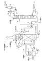
- FIG. 1 is a schematic view of a CO 2 recovery device provided with a gas-liquid contact device according to the first embodiment.
- FIG. 2 is a schematic perspective view of the internal structure of the gas-liquid contact device according to the first embodiment.
- FIG. 3 is a schematic perspective view of a unit unit in the gas-liquid contact device according to the first embodiment.
- FIG. 4 is a schematic perspective view of a unit unit in the gas-liquid contact device according to the second embodiment.
- FIG. 5 is a schematic perspective view of a unit unit in the gas-liquid contact device according to the third embodiment.
- FIG. 6 is a schematic perspective view of the gas-liquid contact device according to the fourth embodiment.
- FIG. 7 is a diagram showing the results of Examples and Comparative Examples.
- FIG. 1 is a schematic view of a CO 2 recovery device provided with a gas-liquid contact device according to a first embodiment of the present invention.
- the CO 2 recovery apparatus 10 as to recover the CO 2 high-concentration CO 2 gas 55 in the flue gas 11 containing CO 2 discharged from industrial facilities such as boilers and gas turbines It is a device for discharging.
- the CO 2 recovery apparatus 10 includes a cooling tower 13 for exhaust gas 11 containing CO 2 is introduced, and the CO 2 absorber 15 provided downstream of the cooling tower 13, downstream of the CO 2 absorption tower 15 And a regeneration tower 17 provided.
- the cooling tower 13 cools the exhaust gas 11 containing CO 2 with water 12.
- the CO 2 absorber 15, and a CO 2 absorbing liquid 14 to absorb the cooling off-gas 11 is cooled in 13 and CO 2 is contacted with CO 2 removed from the flue gas 11.
- a CO 2 absorption liquid 14 circulates between the CO 2 absorption tower 15 and the regeneration tower 17.
- the CO 2 absorption liquid 14 (lean solution) is fed to the regeneration tower 17 as a CO 2 absorption liquid (rich solution) 16 that has absorbed CO 2 in the CO 2 absorption tower 15.
- the CO 2 absorbing solution (rich solution) 16 is fed to the CO 2 absorbing tower 15 as a CO 2 absorbing solution (lean solution) 14 that has been regenerated by removing almost all of the CO 2 in the regenerating tower 17.
- the exhaust gas 11 containing CO 2 is pressurized by an exhaust gas blower or the like, then sent to the cooling tower 13, and cooled by countercurrent contact with the water 12 in the cooling tower 13.
- the water 12 heated to high temperature by exchanging heat with the exhaust gas 11 is extracted from the bottom of the cooling tower 13, cooled by the cooling water 18, and circulated as cooling water for the exhaust gas 11.
- the cooled exhaust gas 11 is discharged to a flue 19 provided between the cooling tower 13 and the CO 2 absorption tower 15.
- Exhaust gas 11 discharged from the cooling tower 13 is sent from the supply port 20 provided in the side wall of the bottom of the CO 2 absorber 15 via the flue 19 to the CO 2 absorber 15.
- the CO 2 absorption tower 15 is provided with a gas-liquid contact device 100 for bringing the CO 2 absorption liquid 14 (for example, a basic amine compound) and the exhaust gas 11 into counterflow contact with each other on the lower side.
- the gas-liquid contact device 100 is filled with a filler part 110 (not shown in FIG. 1, refer to FIG. 2), and a liquid dispersion in which a CO 2 absorbing liquid 14 is supplied to the upper part of the filler part 110.
- a container 120 (not shown in FIG. 1, see FIG. 2 etc.) is provided.
- the CO 2 absorption tower 15 has a water washing section 42 and a demister 43 on the upper side of the gas-liquid contact device 100.
- CO 2 flue gas 41 from which CO 2 has been removed after the CO 2 absorbing liquid 14 that is entrained CO 2 flue gas 41 in the water washing section 42 and the demister 43 is removed, is discharged from the top to the outside of the system .
- the rich solution 16 that has absorbed CO 2 in the exhaust gas 11 is stored at the bottom of the CO 2 absorption tower 15.
- Rich solution 16 stored in the bottom of the CO 2 absorber 15 is pumped by a rich solution discharge pump 44 provided outside the bottom of the CO 2 absorber 15.
- the rich solution 16 is heat-exchanged with the CO 2 absorbent 14 regenerated in the regeneration tower 17 in the rich / lean solution heat exchanger 45 and then supplied into the regeneration tower 17 from the top of the tower.
- the regeneration tower 17 releases CO 2 from the rich solution 16 and regenerates it as the lean solution 14.
- the rich solution 16 released from the top of the tower into the regeneration tower 17 is a CO 2 absorbent (lean solution) in which most of the CO 2 is released by endotherm and almost all of the CO 2 is removed at the bottom of the regeneration tower 17. ) 14.
- the lean solution 14 stored at the bottom of the regeneration tower 17 is supplied as a CO 2 absorbing solution by a lean solvent pump 46 and is cooled by exchanging heat with cooling water 48 in a lean solvent cooler 47, and then absorbing CO 2. Sent to tower 15. On the other hand, CO 2 gas 51 accompanied by water vapor is released from the top of the regeneration tower 17.
- the water vapor contained in the CO 2 gas 51 is condensed by the cooling water 53 by the condenser 52 and the water 56 is separated by the separation drum 54.
- the CO 2 gas 55 is discharged out of the system and recovered.
- the water 56 separated by the separation drum 54 is supplied to the upper portion of the regeneration tower 17 by a condensed water circulation pump 57.
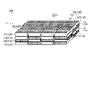
- FIG. 2 is a schematic perspective view of the internal structure of the gas-liquid contact device 100 according to the present embodiment.
- the gas-liquid contact device 100 includes a filler part 110 through which the exhaust gas 11 passes and a liquid distributor 120 provided on the filler part 110, respectively.
- a plurality of unit units 101 are arranged side by side (eight in this embodiment).
- the filler part 110 has a generally rectangular parallelepiped shape, and the first filler layer 111, the second filler layer 112, and the third filler layer 113 are in contact with each other along the flow direction of the exhaust gas 11, respectively. They are stacked in order.
- the liquid disperser 120 is disposed above the third filler layer 113 so as to be downstream of the filler part 110 in the flow direction D1 of the exhaust gas 11.
- the liquid disperser 120 generally has a substantially rectangular parallelepiped shape, and a liquid disperser body 121 having a flow path 121a (not shown in FIG. 2, refer to FIG. 3) for the CO 2 absorbing liquid 14 on its surface, And a liquid supply part 122 for the CO 2 absorbent 14 provided on the upper surface of the disperser body 121.
- the gas-liquid contact device is not configured by the single filler part 110 and the liquid distributor 120, but the unit unit 101 having the plurality of filler parts 110 and the liquid distributor 120. Are placed side by side.
- the gas-liquid contact device 100 can prevent the liquid drift of the CO 2 absorbing liquid 14 in the liquid disperser 120 even when the entire apparatus is enlarged, and the unit-to-unit unit 101 can be connected to the adjacent unit unit 101. Expansion of gas-liquid drift to the filler 110 can be prevented.
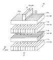
- FIG. 3 is a schematic perspective view of the unit unit 101 in the gas-liquid contact device 100 according to the present embodiment.
- the first filler layer 111, the second filler layer 112, and the third filler layer 113 are shown separated from each other for convenience of explanation.
- the liquid supply unit 122 of the liquid disperser 120 has a generally rectangular parallelepiped shape and is provided at the center of the liquid disperser 120.
- the liquid supply unit 122 has an open upper end and is configured to be able to supply the CO 2 absorbent 14 from above to the inside.
- a plurality of liquid supply ports 122 a are provided on the bottom surface of the liquid supply unit 122.
- the liquid disperser body 121 is generally in the shape of a substantially rectangular parallelepiped, and a plurality of CO 2 absorbing liquid flow paths 121 a are provided substantially in parallel in a direction substantially perpendicular to the flow direction D 1 of the exhaust gas 11. With this configuration, the CO 2 absorbing liquid 14 supplied into the liquid supply unit 122 is dispersed from the liquid supply port 122a through the flow path 121a of the liquid distributor main body 121, and below the liquid distributor 120. Are distributed from the lower surface side of the liquid disperser 120 and supplied to the filler 110 arranged in the above.
- the first filler layer 111, the second filler layer 112, and the third filler layer 113 of the filler portion 110 are each configured as a substantially rectangular parallelepiped plate member.
- Each of the first filler layer 111, the second filler layer 112, and the third filler layer 113 is configured by laminating a plurality of flat plate-like members, and the CO 2 absorbent 14 is provided in the gaps between the plate-like members.
- the flow paths 111a, 112a, 113a are provided.
- the first filler layer 111, the second filler layer 112, and the third filler layer 113 are provided with flow paths 111a to 113a through which the CO 2 absorbent 14 flows, respectively.
- the gas-liquid contact device 100 improves the dispersibility of the CO 2 absorbing liquid 14 in the first filler layer 111, the second filler layer 112, and the third filler layer 113. Gas-liquid drift in the plurality of filler portions 110 can be prevented.
- the extending direction D2 of the flow path 111a of the first filler layer 111 and the extending direction D3 of the flow path 112a of the second filler layer 112 are mutually different. They are stacked in different directions.
- the second filler layer 112 and the third filler layer 113 have an extending direction D3 of the flow path 112a of the second filler layer 112 and an extending direction D2 of the flow path 113a of the third filler layer 113. They are arranged in different directions.
- the first filler layer 111 and the second filler layer 112 have an extension direction D2 of the flow path 111a of the first filler layer 111 and an extension of the flow path 112a of the second filler layer 112.
- the layers are stacked so that the direction D3 is substantially perpendicular to the direction D3.
- the second filler layer 112 and the third filler layer 113 have an extending direction D3 of the flow path 112a of the second filler layer 112 and an extending direction D2 of the flow path 113a of the third filler layer 113. They are arranged so as to be substantially orthogonal.
- the first filler layer 111, the second filler layer 112, and the third filler layer 113 have substantially the extending direction D2 of the flow paths 111a and 113a of the first filler layer 111 and the third filler layer 113. Arranged to match. And the extending direction D3 of the flow path of the 2nd filler layer 112 arrange
- the flow paths 111a and 113a of the 113 are arranged so as to be substantially orthogonal to the extending direction D2.
- the CO 2 absorbing liquid 14 dispersed by the liquid disperser 120 and flowing down to the third filler layer 113 extends in the extending direction by the flow path 113a of the third filler layer 113. Dispersed along D ⁇ b> 2 and flows down to the second filler layer 112. The CO 2 absorbent 14 that has flowed down to the second filler layer 112 is dispersed along the extending direction D3 of the flow path 112a of the second filler layer 112 and flows down to the first filler layer 111.
- the CO 2 absorbent 14 flowing down to the first filler layer 111 is dispersed along the extending direction D2 of the flow path 111a of the first filler layer 111 to become the rich solution 16 and the CO 2 absorber 15. It is stored in the lower part of.
- the CO 2 absorbing liquid 14 flows down in the filler portion 110 while being dispersed in different directions, so that liquid drift in the liquid disperser can be prevented even when the entire apparatus is enlarged. Can do.
- the entire apparatus is enlarged. Even in this case, liquid drift in the liquid disperser 120 can be prevented.
- the first filler layer 111, the second filler layer 112, and the third filler layer 111 are different from each other in the extending directions D2 and D3 of the flow paths 111a to 113a of the CO 2 absorbent 14 dispersed by the liquid distributor 120. Since the filler layer 113 is laminated, gas-liquid drift in the plurality of filler portions 110 can be prevented.
- the gas-liquid contact apparatus 100 since the plurality of filler portions 110 are provided in the apparatus, it is possible to prevent the gas-liquid drift from spreading to the adjacent filler portions 110. Therefore, even if the gas-liquid contact apparatus 100 is a case where the whole apparatus is enlarged, the gas-liquid contact apparatus 100 which can reduce the gas-liquid drift in an apparatus and can prevent the fall of gas absorption performance is realizable.
- the first filler layer 111, the second filler layer 112, and the third filler layer 111 are stacked.
- the dispersibility of the liquid in the filler layer 113 is improved, and gas-liquid drift in the plurality of filler portions 110 can be further prevented.
- the filler portion 110 is configured by stacking three layers of the first filler layer 111, the second filler layer 112, and the third filler layer 113 has been described. It is not limited to the configuration.
- the filler part 110 may be configured by laminating at least two layers.
- liquid disperser 120 is not particularly limited as long as it can disperse the CO 2 absorbing liquid 14 and supply it to the filler part 110.
- gas-liquid contact apparatus 100 description has been given of the case using the CO 2 absorption tower 15 of the CO 2 recovery apparatus 10, the present embodiment is not limited thereto, for example, cooling towers 13 may be used.
- FIG. 4 is a schematic perspective view of the unit unit 201 in the gas-liquid contact device 100 according to the present embodiment.
- the first filler layer 211, the second filler layer 212, and the third filler layer 213 are shown apart from each other for convenience of explanation.
- a filler part 210 is disposed below the liquid distributor 120.
- the filler part 210 is configured by laminating a first filler layer 211, a second filler layer 212, and a third filler layer 213.
- the first filler layer 211, the second filler layer 212, and the third filler layer 213 of the filler portion 210 are each configured as a generally rectangular parallelepiped plate-like member.
- Each of the first filler layer 211, the second filler layer 212, and the third filler layer 213 is configured by obliquely laminating a plurality of plate-like members, and the CO 2 absorbing liquid 14 is interposed between the plate-like members.
- Channels 211a, 212a, and 213a are provided. That is, in the present embodiment, the flow paths 211a, 212a, and 213a of the CO 2 absorbent 14 are provided obliquely with respect to the flow direction D1 of the exhaust gas 11.
- the flow paths 211a, 212a, and 213a of the CO 2 absorbent 14 are provided obliquely with respect to the flow direction D1 of the exhaust gas 11.
- the residence time of the CO 2 absorbing liquid 14 in the filler part 210 becomes longer, so that the dispersibility of the CO 2 absorbing liquid 14 is improved and the gas-liquid drift in the filler part 210 is further increased. This can be further prevented.
- FIG. 5 is a schematic perspective view of the unit unit 301 in the gas-liquid contact device 100 according to the third embodiment of the present invention.
- the first filler layer 311, the second filler layer 312, and the third filler layer 313 are shown apart from each other for convenience of explanation.
- a filler part 310 is disposed below the liquid distributor 120.
- the filler part 310 is configured by laminating a first filler layer 311, a second filler layer 312, and a third filler layer 313.
- the first filler layer 311, the second filler layer 312, and the third filler layer 313 of the filler portion 310 are each configured as a substantially rectangular parallelepiped plate member.
- the first filler layer 311, the second filler layer 312, and the third filler layer 313 are each configured by obliquely laminating a plurality of corrugated plate-like members, and CO 2 between each plate-like member.
- Flow paths 311a, 312a, and 313a for the absorbing liquid 14 are provided. That is, in the present embodiment, the flow paths 311a, 312a, and 313a of the CO 2 absorbent 14 are provided in a wave shape with respect to the extending directions D2 and D3 of the flow paths 311a, 312a, and 313a of the exhaust gas 11.
- the structure since it has the structure same as the gas-liquid contact apparatus 100 which concerns on 1st Embodiment mentioned above, description is abbreviate
- the residence time of the CO 2 absorbing liquid 14 in the filler part 310 becomes longer, so that the dispersibility of the CO 2 absorbing liquid 14 is improved and the gas-liquid drift in the filler part 310 is further reduced. This can be further prevented.
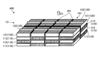
- FIG. 6 is a schematic perspective view of a gas-liquid contact device 400 according to the fourth embodiment of the present invention.
- the gas-liquid contact device 400 according to the present embodiment includes a filler part 110 through which the exhaust gas 11 passes, and a liquid distributor 120 provided on the filler part 110.
- a plurality of unit units 101 are arranged side by side (eight in this embodiment).
- a partition member 401 that partitions each unit unit 101 is provided between each unit unit 101.
- the partition member 401 since the plurality of filler portions 110 are partitioned by the partition member 401, the spread of gas-liquid drift to the adjacent filler layer can be further prevented.
- the example shown in FIG. 6 the example in which the flat partition member 401 is arranged has been described.
- the shape of the partition member 401 is not necessarily flat so long as each unit unit 101 can be partitioned. There is no need to be on top.
- Example 2 Next, examples performed for clarifying the effects of the present invention will be described.
- the inventors have described conventional gas-liquid contact devices 100 (Example 1) according to the first embodiment and gas-liquid contact devices 400 (Example 2) according to the fourth embodiment.
- the CO 2 absorption ratio was evaluated based on the liquid contact device (comparative example). The result is shown in FIG.
- the gas-liquid contact device 100 according to the first embodiment provided with a plurality of unit units 101 including a filler part 110 and a liquid distributor 120 is different from the conventional gas-liquid contact device.
- the CO 2 absorption ratio was about 1.04 times.
- the gas-liquid contact device 400 according to the fourth embodiment in which the partition member 401 is disposed between the plurality of unit units 101 has a CO 2 absorption rate of about 1.05 times that of the conventional gas-liquid contact device. The ratio is shown. This result is considered to be because the plurality of filler portions 110 are divided by the partition member 401, so that the spread of gas-liquid drift to the adjacent filler portions 110 can be further prevented.
- CO 2 recovery device 11 the exhaust gas 12,56 Water 13 cooling tower 14 CO 2 absorbing liquid 15 CO 2 absorption tower 16 rich solution 17 regenerator 18,48,53 coolant 19 flue 20 supply port 41 CO 2 flue gas 42 washing Unit 43 demister 44 rich solution discharge pump 45 rich lean solution heat exchanger 46 lean solvent pump 47 lean solvent cooler 51, 55 CO 2 gas 52 condenser 54 separation drum 57 condensed water circulation pump 100, 400 gas-liquid contact device 101, 201, 301 Unit unit 110, 210, 310 Filler part 111, 211, 311 First filler layer 111a, 211a, 311a Channel 112, 212, 312 Second filler layer 112a, 212a, 312a Channel 113, 213, 313 Third filler layer 113 , 213a, 313a flow path 120 liquid distributor 121 liquid distributor body 121a passage 122 liquid supply part 122a fluid supply opening 401 partition member
Abstract
Description
図1は、本発明の第1の実施形態に係る気液接触装置を備えたCO2回収装置の概略図である。図1に示すように、このCO2回収装置10は、ボイラやガスタービンなどの産業設備から排出されたCO2を含有する排ガス11中のCO2を回収して高濃度のCO2ガス55として排出する装置である。このCO2回収装置10は、CO2を含有する排ガス11が導入される冷却塔13と、この冷却塔13の後段に設けられたCO2吸収塔15と、このCO2吸収塔15の後段に設けられた再生塔17とを具備する。 (First embodiment)
FIG. 1 is a schematic view of a CO 2 recovery device provided with a gas-liquid contact device according to a first embodiment of the present invention. As shown in FIG. 1, the CO 2 recovery apparatus 10, as to recover the CO 2 high-concentration CO 2 gas 55 in the
次に、本発明の第2の実施の形態について説明する。なお、以下においては、上述した第1の実施の形態に係る気液接触装置100と共通する構成要素には同一の符号を付し、説明の重複を避ける。 (Second Embodiment)
Next, a second embodiment of the present invention will be described. In the following description, constituent elements common to the gas-
図5は、本発明の第3の実施の形態に係る気液接触装置100における単位ユニット301の模式的な斜視図である。なお、図5においては、説明の便宜上、第1充填材層311、第2充填材層312及び第3充填材層313を離間して示している。図5に示すように、本実施の形態においては、液分散器120の下方に充填材部310が配置される。この充填材部310は、第1充填材層311、第2充填材層312及び第3充填材層313が積層されて構成される。充填材部310の第1充填材層311、第2充填材層312及び第3充填材層313は、それぞれ概して略直方体形状の板状部材として構成されている。第1充填材層311、第2充填材層312及び第3充填材層313は、それぞれ複数の波板状の板状部材が斜めに積層して構成され、各板状部材の間にCO2吸収液14の流路311a、312a、313aが設けられている。すなわち、本実施の形態においては、CO2吸収液14の流路311a、312a、313aが排ガス11の流路311a、312a、313aの延在方向D2,D3に対して波状に設けられている。その他の構成については、上述した第1の実施の形態に係る気液接触装置100と同一の構成を有するので説明を省略する。 (Third embodiment)
FIG. 5 is a schematic perspective view of the
図6は、本発明の第4の実施の形態に係る気液接触装置400の模式的な斜視図である。図6に示すように、本実施の形態に係る気液接触装置400は、内部に排ガス11が通過する充填材部110と、この充填材部110上にそれぞれ設けられた液分散器120とを有する単位ユニット101が複数並設(本実施の形態では8つ)して配置されている。各単位ユニット101の間には、各単位ユニット101を仕切る仕切部材401が設けられている。その他の構成については、上述した第1の実施の形態に係る気液接触装置100と同一の構成を有するので説明を省略する。 (Fourth embodiment)
FIG. 6 is a schematic perspective view of a gas-
次に、本発明の効果を明確にするために行った実施例について説明する。本発明者らは、上述した第1の実施の形態に係る気液接触装置100(実施例1)及び第4の実施の形態に係る気液接触装置400(実施例2)について、従来の気液接触装置(比較例)を基準としてCO2吸収率比を評価した。その結果を図7に示す。図7に示すように、充填材部110及び液分散器120を備えた単位ユニット101を複数設けた上記第1の実施の形態に係る気液接触装置100は、従来の気液接触装置に対して約1.04倍のCO2吸収率比を示した。この結果は、液分散器120での液偏流、複数の充填材部110内における気液偏流及び隣接する充填材部110への気液偏流の拡大を防ぐことができたためと考えられる。また、複数の単位ユニット101間に仕切部材401を配置した上記第4の実施の形態に係る気液接触装置400は、従来の気液接触装置に対して約1.05倍のCO2吸収率比を示した。この結果は、仕切部材401によって複数の充填材部110が区分されるので、隣接する充填材部110への気液偏流の拡大をより一層防ぐことができたためと考えられる。 (Example)
Next, examples performed for clarifying the effects of the present invention will be described. The inventors have described conventional gas-liquid contact devices 100 (Example 1) according to the first embodiment and gas-liquid contact devices 400 (Example 2) according to the fourth embodiment. The CO 2 absorption ratio was evaluated based on the liquid contact device (comparative example). The result is shown in FIG. As shown in FIG. 7, the gas-
11 排ガス
12、56 水
13 冷却塔
14 CO2吸収液
15 CO2吸収塔
16 リッチ溶液
17 再生塔
18、48、53 冷却水
19 煙道
20 供給口
41 CO2除去排ガス
42 水洗部
43 デミスタ
44 リッチ溶液排出ポンプ
45 リッチ・リーン溶液熱交換器
46 リーンソルベントポンプ
47 リーンソルベントクーラ
51、55 CO2ガス
52 コンデンサ
54 分離ドラム
57 凝縮水循環ポンプ
100、400 気液接触装置
101、201、301 単位ユニット
110、210、310 充填材部
111、211、311 第1充填材層
111a、211a、311a 流路
112、212、312 第2充填材層
112a、212a、312a 流路
113、213、313 第3充填材層
113a、213a、313a 流路
120 液分散器
121 液分散器本体
121a 流路
122 液供給部
122a 液供給口
401 仕切部材 10 CO 2 recovery device 11 the
Claims (7)
- 被処理気体が通過する複数の充填材部と、
前記複数の充填材部上にそれぞれ設けられ、前記被処理気体と接触させる液体を分散させて前記複数の充填材部に供給する複数の液分散器とを備え、
前記複数の充填材部は、前記液体の流路がそれぞれ所定方向に延在して設けられた第1充填材層及び第2充填材層を含み、
前記第1充填材層及び前記第2充填材層は、前記被処理気体の流れ方向において前記流路の延在方向が相互に異なるように積層されたことを特徴とする、気液接触装置。 A plurality of filler parts through which the gas to be treated passes;
A plurality of liquid distributors provided on the plurality of filler parts, respectively, and supplying a liquid to be contacted with the gas to be processed and supplying the liquids to the filler parts;
The plurality of filler portions include a first filler layer and a second filler layer provided with the liquid flow paths extending in predetermined directions, respectively.
The gas-liquid contact device, wherein the first filler layer and the second filler layer are laminated so that the extending directions of the flow paths are different from each other in the flow direction of the gas to be processed. - 前記第1充填材層及び前記第2充填材層は、前記流路の延在方向が相互に略直交するように積層された、請求項1に記載の気液接触装置。 The gas-liquid contact device according to claim 1, wherein the first filler layer and the second filler layer are laminated so that the extending directions of the flow paths are substantially orthogonal to each other.
- 前記第1充填材層及び前記第2充填材層は、前記流路が前記被処理気体の流れ方向に対して斜めに設けられた、請求項1又は請求項2に記載の気液接触装置。 The gas-liquid contact device according to claim 1 or 2, wherein the first filler layer and the second filler layer are provided with the flow path obliquely with respect to a flow direction of the gas to be processed.
- 前記第1充填材層及び前記第2充填材層が、板状充填材である、請求項1から請求項3のいずれか1項に記載の気液接触装置。 The gas-liquid contact device according to any one of claims 1 to 3, wherein the first filler layer and the second filler layer are plate-like fillers.
- 前記板状充填材の形状が波板又は平板状である、請求項1から請求項4のいずれか1項に記載の気液接触装置。 The gas-liquid contact device according to any one of claims 1 to 4, wherein a shape of the plate-like filler is a corrugated plate or a flat plate shape.
- 前記複数の充填材部間に設けられ、前記複数の充填材部間を仕切る仕切部材を有する、請求項1から請求項5のいずれか1項に記載の気液接触装置。 The gas-liquid contact device according to any one of claims 1 to 5, further comprising a partition member provided between the plurality of filler portions and partitioning the plurality of filler portions.
- 請求項1から請求項6のいずれか1項に記載の気液接触装置を備え、CO2を含む排ガスとCO2を吸収するCO2吸収液とを接触させて前記排ガスからCO2を除去するCO2吸収塔と、
CO2を吸収したCO2吸収液からCO2を放出させてCO2吸収液を再生する再生塔と、
を具備することを特徴とするCO2回収装置。 Comprising a gas-liquid contact apparatus according to any one of claims 1 to 6 is brought into contact with CO 2 absorbing liquid to absorb the exhaust gas and CO 2 containing CO 2 removing CO 2 from the exhaust gas A CO 2 absorption tower,
A regenerator to regenerate the CO 2 absorbing liquid CO 2 from the absorbed CO 2 absorbing solution by releasing CO 2,
A CO 2 recovery device comprising:
Priority Applications (4)
| Application Number | Priority Date | Filing Date | Title |
|---|---|---|---|
| EP15740340.3A EP3067114A4 (en) | 2014-01-27 | 2015-01-13 | Gas-liquid contactor and co2 recovery device |
| CA2932711A CA2932711A1 (en) | 2014-01-27 | 2015-01-13 | Gas-liquid contactor and co2 recovery device |
| AU2015210222A AU2015210222B2 (en) | 2014-01-27 | 2015-01-13 | Gas-liquid contactor and CO2 recovery device |
| US15/102,141 US9919267B2 (en) | 2014-01-27 | 2015-01-13 | Gas-liquid contactor and CO2 recovery device |
Applications Claiming Priority (2)
| Application Number | Priority Date | Filing Date | Title |
|---|---|---|---|
| JP2014012720A JP6460629B2 (en) | 2014-01-27 | 2014-01-27 | Gas-liquid contact device and CO2 recovery device |
| JP2014-012720 | 2014-01-27 |
Publications (1)
| Publication Number | Publication Date |
|---|---|
| WO2015111463A1 true WO2015111463A1 (en) | 2015-07-30 |
Family
ID=53681271
Family Applications (1)
| Application Number | Title | Priority Date | Filing Date |
|---|---|---|---|
| PCT/JP2015/050662 WO2015111463A1 (en) | 2014-01-27 | 2015-01-13 | Gas-liquid contactor and co2 recovery device |
Country Status (6)
| Country | Link |
|---|---|
| US (1) | US9919267B2 (en) |
| EP (1) | EP3067114A4 (en) |
| JP (1) | JP6460629B2 (en) |
| AU (1) | AU2015210222B2 (en) |
| CA (1) | CA2932711A1 (en) |
| WO (1) | WO2015111463A1 (en) |
Families Citing this family (5)
| Publication number | Priority date | Publication date | Assignee | Title |
|---|---|---|---|---|
| CN106000008B (en) * | 2016-07-11 | 2019-03-15 | 南通星球石墨设备有限公司 | A kind of quenching absorption tower |
| US11446603B2 (en) * | 2017-07-06 | 2022-09-20 | Qatar Foundation For Education, Science, Andcommunity Development | Acid gas removal system for removing acidic gases from gaseous hydrocarbons |
| EP3424590A1 (en) * | 2017-07-07 | 2019-01-09 | Linde Aktiengesellschaft | Package for material and/or energy exchange with separate packaging units |
| CN108187999A (en) * | 2017-12-28 | 2018-06-22 | 郑州天舜电子技术有限公司 | A kind of efficient Chemical Manufacture material screening equipment |
| JP7412102B2 (en) * | 2019-07-24 | 2024-01-12 | 三菱重工業株式会社 | gas turbine plant |
Citations (10)
| Publication number | Priority date | Publication date | Assignee | Title |
|---|---|---|---|---|
| JPS49125604A (en) * | 1973-04-11 | 1974-12-02 | ||
| JPS5095439U (en) * | 1973-12-29 | 1975-08-09 | ||
| JPS51126970A (en) * | 1975-04-30 | 1976-11-05 | Gadelius Kk | A packing for vapor-liquid contact tow towers |
| JPS5217369A (en) * | 1975-06-06 | 1977-02-09 | Seghers Eng Nv | Packing material for gassliquid contact apparatus |
| JPS5326352U (en) * | 1976-08-13 | 1978-03-06 | ||
| JPS5624029A (en) * | 1979-08-06 | 1981-03-07 | Kureha Chem Ind Co Ltd | Removal of sulfur dioxide gas in exhaust gas |
| JPH06269629A (en) | 1993-03-19 | 1994-09-27 | Kansai Electric Power Co Inc:The | Gas/liquid contact device |
| JPH08276101A (en) * | 1994-12-29 | 1996-10-22 | Boc Group Inc:The | Liquid-vapor contact column |
| JP2003517919A (en) * | 1998-07-02 | 2003-06-03 | エービービー フラクト アクチボラグ | Liquid delivery part of contact device |
| JP2012232292A (en) * | 2011-04-18 | 2012-11-29 | Ihi Corp | Absorption tower, and biological deodorization apparatus using the same |
Family Cites Families (8)
| Publication number | Priority date | Publication date | Assignee | Title |
|---|---|---|---|---|
| EP0069241B1 (en) | 1981-07-08 | 1985-09-11 | Kühni AG | Packing for material exchange columns, and process for producing the packing |
| CH658198A5 (en) | 1983-01-04 | 1986-10-31 | Sulzer Ag | LIQUID DISTRIBUTOR IN A SUBSTANCE AND HEAT EXCHANGE COLUMN. |
| BR8403035A (en) * | 1983-06-21 | 1985-05-28 | Glitsch | PERFECTED TOWER FILLING GRID AND PERFECTED PROCESS TO PERFORM THE STEAM AND LIQUID CONTACT |
| JPH086499Y2 (en) * | 1990-09-25 | 1996-02-28 | 日鉄化工機株式会社 | Liquid disperser |
| JPH07121357B2 (en) | 1991-08-20 | 1995-12-25 | 日本ポリエステル株式会社 | Gas-liquid contact unit and gas-liquid contact device |
| EP0776695B1 (en) * | 1995-11-29 | 2002-04-17 | Sulzer Chemtech AG | Packing for a high-pressure counterflow column |
| PE20071048A1 (en) * | 2005-12-12 | 2007-10-18 | Basf Ag | PROCESS FOR THE RECOVERY OF CARBON DIOXIDE |
| FR2907025B1 (en) * | 2006-10-11 | 2009-05-08 | Inst Francais Du Petrole | CO2 CAPTURE PROCESS WITH THERMAL INTEGRATION OF REGENERATOR. |
-
2014
- 2014-01-27 JP JP2014012720A patent/JP6460629B2/en active Active
-
2015
- 2015-01-13 WO PCT/JP2015/050662 patent/WO2015111463A1/en active Application Filing
- 2015-01-13 AU AU2015210222A patent/AU2015210222B2/en not_active Ceased
- 2015-01-13 EP EP15740340.3A patent/EP3067114A4/en not_active Withdrawn
- 2015-01-13 CA CA2932711A patent/CA2932711A1/en active Pending
- 2015-01-13 US US15/102,141 patent/US9919267B2/en not_active Expired - Fee Related
Patent Citations (10)
| Publication number | Priority date | Publication date | Assignee | Title |
|---|---|---|---|---|
| JPS49125604A (en) * | 1973-04-11 | 1974-12-02 | ||
| JPS5095439U (en) * | 1973-12-29 | 1975-08-09 | ||
| JPS51126970A (en) * | 1975-04-30 | 1976-11-05 | Gadelius Kk | A packing for vapor-liquid contact tow towers |
| JPS5217369A (en) * | 1975-06-06 | 1977-02-09 | Seghers Eng Nv | Packing material for gassliquid contact apparatus |
| JPS5326352U (en) * | 1976-08-13 | 1978-03-06 | ||
| JPS5624029A (en) * | 1979-08-06 | 1981-03-07 | Kureha Chem Ind Co Ltd | Removal of sulfur dioxide gas in exhaust gas |
| JPH06269629A (en) | 1993-03-19 | 1994-09-27 | Kansai Electric Power Co Inc:The | Gas/liquid contact device |
| JPH08276101A (en) * | 1994-12-29 | 1996-10-22 | Boc Group Inc:The | Liquid-vapor contact column |
| JP2003517919A (en) * | 1998-07-02 | 2003-06-03 | エービービー フラクト アクチボラグ | Liquid delivery part of contact device |
| JP2012232292A (en) * | 2011-04-18 | 2012-11-29 | Ihi Corp | Absorption tower, and biological deodorization apparatus using the same |
Non-Patent Citations (1)
| Title |
|---|
| See also references of EP3067114A4 |
Also Published As
| Publication number | Publication date |
|---|---|
| EP3067114A1 (en) | 2016-09-14 |
| CA2932711A1 (en) | 2015-07-30 |
| US9919267B2 (en) | 2018-03-20 |
| JP2015139727A (en) | 2015-08-03 |
| EP3067114A4 (en) | 2017-02-08 |
| US20160310894A1 (en) | 2016-10-27 |
| AU2015210222A1 (en) | 2016-06-23 |
| AU2015210222B2 (en) | 2017-07-13 |
| JP6460629B2 (en) | 2019-01-30 |
Similar Documents
| Publication | Publication Date | Title |
|---|---|---|
| WO2015111463A1 (en) | Gas-liquid contactor and co2 recovery device | |
| JP7054116B2 (en) | Equipment and methods for recovering carbon dioxide in combustion exhaust gas | |
| JP5875245B2 (en) | CO2 recovery system and CO2 gas-containing moisture recovery method | |
| JP7106954B2 (en) | carbon dioxide recovery equipment | |
| US20110126715A1 (en) | Carbon dioxide gas recovery apparatus | |
| JP6855765B2 (en) | Gas-liquid contact device | |
| US10065149B2 (en) | Gas-liquid contactor and CO2-recovering apparatus provided therewith | |
| JP2016117060A (en) | Distributor tray for exchange column exchanging heat and/or material comprising bubbling means | |
| WO2019207671A1 (en) | Gas-liquid contact device | |
| JP5693076B2 (en) | Gas-liquid contact device and CO2 recovery device | |
| RU2682606C2 (en) | Distribution plate for exchange column between gas and liquid with liquid defector, heat exchange column and use thereof | |
| US10213727B2 (en) | CO2 recovery device and CO2 recovery method | |
| JP6990099B2 (en) | Carbon dioxide capture system and its operation method | |
| JP6862251B2 (en) | How to operate the carbon dioxide capture system and the carbon dioxide capture system | |
| WO2021152882A1 (en) | Gas treatment device and gas treatment method | |
| JP7189747B2 (en) | CO2 RECOVERY SYSTEM AND METHOD OF OPERATION THEREOF | |
| JP2018124049A (en) | Absorption refrigerating machine | |
| WO2022074976A1 (en) | Gas-treating device | |
| JP2019115872A (en) | Carbon dioxide recovery system and operation method of carbon dioxide recovery system | |
| JP2015097986A (en) | Distillation column, liquid heating method, and carbon dioxide recovery apparatus and carbon dioxide recovery method using the same | |
| JP2021178302A (en) | Gas-liquid contact device |
Legal Events
| Date | Code | Title | Description |
|---|---|---|---|
| 121 | Ep: the epo has been informed by wipo that ep was designated in this application |
Ref document number: 15740340 Country of ref document: EP Kind code of ref document: A1 |
|
| ENP | Entry into the national phase |
Ref document number: 2932711 Country of ref document: CA |
|
| WWE | Wipo information: entry into national phase |
Ref document number: 15102141 Country of ref document: US |
|
| REEP | Request for entry into the european phase |
Ref document number: 2015740340 Country of ref document: EP |
|
| WWE | Wipo information: entry into national phase |
Ref document number: 2015740340 Country of ref document: EP |
|
| ENP | Entry into the national phase |
Ref document number: 2015210222 Country of ref document: AU Date of ref document: 20150113 Kind code of ref document: A |
|
| NENP | Non-entry into the national phase |
Ref country code: DE |