WO2015111336A1 - 無線通信システム、基地局装置、端末装置、無線通信方法および集積回路 - Google Patents
無線通信システム、基地局装置、端末装置、無線通信方法および集積回路 Download PDFInfo
- Publication number
- WO2015111336A1 WO2015111336A1 PCT/JP2014/083597 JP2014083597W WO2015111336A1 WO 2015111336 A1 WO2015111336 A1 WO 2015111336A1 JP 2014083597 W JP2014083597 W JP 2014083597W WO 2015111336 A1 WO2015111336 A1 WO 2015111336A1
- Authority
- WO
- WIPO (PCT)
- Prior art keywords
- base station
- data
- station apparatus
- information
- station device
- Prior art date
Links
Images


Classifications
-
- H—ELECTRICITY
- H04—ELECTRIC COMMUNICATION TECHNIQUE
- H04W—WIRELESS COMMUNICATION NETWORKS
- H04W72/00—Local resource management
- H04W72/50—Allocation or scheduling criteria for wireless resources
- H04W72/56—Allocation or scheduling criteria for wireless resources based on priority criteria
-
- H—ELECTRICITY
- H04—ELECTRIC COMMUNICATION TECHNIQUE
- H04W—WIRELESS COMMUNICATION NETWORKS
- H04W16/00—Network planning, e.g. coverage or traffic planning tools; Network deployment, e.g. resource partitioning or cells structures
- H04W16/24—Cell structures
- H04W16/32—Hierarchical cell structures
-
- H—ELECTRICITY
- H04—ELECTRIC COMMUNICATION TECHNIQUE
- H04W—WIRELESS COMMUNICATION NETWORKS
- H04W48/00—Access restriction; Network selection; Access point selection
- H04W48/08—Access restriction or access information delivery, e.g. discovery data delivery
- H04W48/12—Access restriction or access information delivery, e.g. discovery data delivery using downlink control channel
-
- H—ELECTRICITY
- H04—ELECTRIC COMMUNICATION TECHNIQUE
- H04W—WIRELESS COMMUNICATION NETWORKS
- H04W48/00—Access restriction; Network selection; Access point selection
- H04W48/16—Discovering, processing access restriction or access information
-
- H—ELECTRICITY
- H04—ELECTRIC COMMUNICATION TECHNIQUE
- H04W—WIRELESS COMMUNICATION NETWORKS
- H04W76/00—Connection management
- H04W76/10—Connection setup
- H04W76/15—Setup of multiple wireless link connections
-
- H—ELECTRICITY
- H04—ELECTRIC COMMUNICATION TECHNIQUE
- H04W—WIRELESS COMMUNICATION NETWORKS
- H04W88/00—Devices specially adapted for wireless communication networks, e.g. terminals, base stations or access point devices
- H04W88/08—Access point devices
Definitions
- the present invention relates to a radio communication system, a base station apparatus, and a terminal apparatus, and more particularly, to a radio communication system, a base station apparatus, a terminal apparatus, a radio communication method, and an integrated circuit related to data control.
- the W-CDMA system is standardized as a third generation cellular mobile communication system, and services are provided. Also, HSDPA with higher communication speed has been standardized and is being serviced.
- EUTRA Evolved Universal Terrestrial Radio Access
- OFDM Orthogonal Frequency Division Division Multiplexing
- PAPR Peak to Average Power Ratio
- Advanced-EUTRA a further evolution of EUTRA.
- communication at a maximum transmission rate of 1 Gbps or more and uplink 500 Mbps or more is performed using a band up to a maximum of 100 MHz bandwidth in uplink and downlink.
- Advanced-EUTRA it is considered to realize a maximum of 100 MHz band by bundling a plurality of bands compatible with EUTRA so as to accommodate EUTRA mobile station apparatuses.
- one band of 20 MHz or less of EUTRA is called a component carrier (Component Carrier: CC).
- the component carrier is also called a cell.
- bundling a band of 20 MHz or less is called carrier aggregation (Carrier Aggregation: CA) (Non-patent Document 1).
- Non-Patent Document 2 in communication between a base station apparatus and a mobile station apparatus during carrier aggregation of a macro cell and a small cell, control information (control plane information: Control-Plane Information) is transmitted by the macro cell, and user information is transmitted by the small cell. It has been proposed to transmit (User-Plane Information).
- control plane information control-Plane Information
- User-Plane Information User-Plane Information
- the same radio bearer (Radio Bearer: RB) information is transmitted from the macro cell base station device and the small cell base station device to the mobile station device, and the same radio bearer (Radio Bearer: RB) information is also transmitted. Is also considered to be transmitted from the mobile station apparatus to the macro cell base station apparatus and the small cell base station apparatus. Note that the control for transmitting and receiving information on the same radio bearer between the base station apparatus and the mobile station apparatus via different base station apparatuses is referred to as bearer split.
- 3GPP TS Technical Specification 36.300, V11.7.0 (2013-09), Evolved Universal Terrestrial Radio Access (E-UTRA) and Evolved Universal Universal Terrestrial Radio Access Network (E-UTRAN), Overall description 3GPP TR (Technical Report) 36.842, V1.0.0 (2013-11), Study on Small Cell Enhancements for E-UTRA and E-UTRAN-Higher layer aspects (release 12)
- Non-Patent Document 2 in communication between the base station apparatus and the mobile station apparatus, bearer division is performed between the macro station base station apparatus and the small cell base station apparatus and the mobile station apparatus to transmit and receive data. In this case, unless an appropriate cell is selected and data transmission / reception is not controlled, the data throughput is lowered.
- the mobile station apparatus when performing bearer division of uplink data from a mobile station apparatus to a macro cell base station apparatus and a small cell base station apparatus, the mobile station apparatus must appropriately select a cell to transmit data.
- the present invention has been made in view of such circumstances, and a radio communication system, a base station apparatus, a mobile station apparatus, and a radio communication method for allowing a mobile station apparatus to efficiently perform data transmission processing at the time of dual connect bearer division And an integrated circuit.
- a wireless communication system is a wireless communication system in which a first base station device and a second base station device communicate with a terminal device, and the first base station device , Transmitting data control information related to data transmission / reception of the terminal device and priority base station device information indicating a priority of data transmission to the base station device to the terminal device, and the terminal device sets bearer division in the data control information Base station apparatus of either the first base station apparatus or the second base station apparatus based on at least one of the priority base station apparatus information and the terminal information of the terminal apparatus Are determined as data transmission destination base station apparatuses.
- the terminal information may be a transmission buffer amount and / or wireless channel quality information of the terminal device.
- a wireless communication system is a wireless communication system in which a first base station device and a second base station device communicate with a terminal device, The base station apparatus transmits data control information related to data transmission / reception of the terminal apparatus to the terminal apparatus using an RRC message, and the first base station apparatus or the second base station apparatus transmits a data transmission destination.
- the terminal apparatus transmits destination base station apparatus information indicating either the first base station apparatus or the second base station apparatus as a base station apparatus to the terminal apparatus using a MAC message,
- the terminal apparatus determines the first base station according to the transmission destination base station apparatus information for data for which bearer division is set in the data control information Equipment Determines any of the base station apparatus of the second base station device as the data transmission destination base station apparatus.
- the first base station device or the second base station device is a base station of the first base station device or the second base station device.
- the device information may be compared to determine the transmission destination base station device information.
- a terminal device is a terminal device that communicates with a first base station device and a second base station device, from the first base station device to the terminal device.
- the priority base station apparatus information Based on at least one of the terminal information of the terminal device, the base station device of either the first base station device or the second base station device is determined as a data transmission destination base station device.
- the terminal information may be a transmission buffer amount and / or radio channel quality information of the terminal device.
- mode of this invention is a terminal device which communicates with a 1st base station apparatus and a 2nd base station apparatus, Comprising: From the said 1st base station apparatus, the said An RRC message including data control information related to data transmission / reception of the terminal device is received, and the first base station device or the first base station device as a data transmission destination base station device from the first base station device or the second base station device.
- a bearer is transmitted with the data control information.
- the data transmission destination base station apparatus is set to either the first base station apparatus or the second base station apparatus in accordance with the transmission destination base station apparatus information for the data for which division is set. As A constant.
- a base station apparatus is a base station apparatus that communicates with a terminal apparatus by connecting to another base station apparatus, and data control information related to data transmission / reception of the terminal apparatus And priority base station apparatus information indicating the priority of data transmission to the base station apparatus is transmitted to the terminal apparatus.
- a base station apparatus is a base station apparatus that communicates with a terminal apparatus by connecting to another base station apparatus, and data control information related to data transmission / reception of the terminal apparatus Is transmitted to the terminal device using the RRC message, and the destination base station device information indicating either the own base station device or the other base station device is used as the data transmission destination base station device using the MAC message. And transmits the uplink transmission permission information of the base station apparatus to the terminal apparatus.
- the base station device information of the other base station device is received from the other base station device, and the base stations of the other base station device and the own base station device are received.
- the station apparatus information may be compared to determine the transmission destination base station apparatus information.
- a wireless communication method is a wireless communication method applied to a wireless communication system in which a first base station device and a second base station device communicate with a terminal device.
- the first base station device transmits data control information related to data transmission / reception of the terminal device and priority base station device information indicating a priority of data transmission to the base station device to the terminal device;
- the terminal device based on at least one of the priority base station device information and the terminal information of the terminal device, for the data for which bearer division is set in the data control information, Determining any one of the second base station devices as a data transmission destination base station device.
- a wireless communication method is a wireless communication method applied to a wireless communication system in which a first base station device and a second base station device communicate with a terminal device.
- the first base station apparatus transmits data control information related to data transmission / reception of the terminal apparatus to the terminal apparatus using an RRC message, and the first base station apparatus or the second base station apparatus
- the base station apparatus uses the destination base station apparatus information indicating either the first base station apparatus or the second base station apparatus as a data transmission destination base station apparatus using a MAC message.
- the transmission destination base station device information for the data for which bearer division is set in the data control information
- the transmission destination base Depending on the device information, and determining one of the base station apparatus of the first base station apparatus or said second base station as a data transmission destination base station apparatus.
- An integrated circuit is an integrated circuit applied to a base station apparatus that communicates with a terminal apparatus by connecting to another base station apparatus, and the terminal apparatus Means for transmitting data control information relating to data transmission / reception to the terminal device using an RRC message, and a destination base indicating either the own base station device or the other base station device as a data transmission destination base station device Means for transmitting station apparatus information to the terminal apparatus using a MAC message; and means for transmitting uplink transmission permission information of the own base station apparatus to the terminal apparatus.
- An integrated circuit is an integrated circuit applied to a terminal device that communicates with a first base station device and a second base station device, Means for receiving data control information related to data transmission / reception of the terminal device and priority base station device information indicating the priority of data transmission to the base station device from the base station device, and data in which bearer division is set by the data control information On the other hand, based on at least one of the priority base station device information and the terminal information of the terminal device, the base station device of either the first base station device or the second base station device transmits data. Means for determining as a destination base station apparatus;
- the mobile station apparatus can perform efficient data transmission to the macro cell base station apparatus or the small cell base station apparatus.
- the OFDM system is adopted as the downlink of EUTRA. Further, a DFT-spread OFDM single carrier communication system is employed as the uplink of EUTRA.
- FIG. 4 is a diagram showing a physical channel configuration of EUTRA.
- the downlink physical channel includes a physical downlink shared channel PDSCH (Physical Downlink Shared Channel), a physical downlink control channel PDCCH (Physical Downlink Control Channel), and a physical broadcast channel PBCH (Physical Broadcast Channel).
- PDSCH Physical Downlink Shared Channel
- PDCCH Physical Downlink Control Channel
- PBCH Physical Broadcast Channel
- there are physical signals such as downlink synchronization signals and downlink reference signals (Non-Patent Document 1).
- the uplink physical channel includes a physical random access channel PRACH (Physical Random Access Channel), a physical uplink shared channel PUSCH (Physical Uplink Shared Channel), and a physical uplink control channel PUCCH (Physical Uplink Control Channel).
- PRACH Physical Random Access Channel
- PUSCH Physical Uplink Shared Channel
- PUCCH Physical Uplink Control Channel
- FIG. 5 is a diagram illustrating a downlink channel configuration of EUTRA.
- the downlink channels shown in FIG. 5 are each composed of a logical channel, a transport channel, and a physical channel.
- the logical channel defines the type of data transmission service that is transmitted and received in a medium access control (MAC) layer.
- the transport channel defines what characteristics the data transmitted over the air interface has and how it is transmitted.
- a physical channel is a physical channel that carries data conveyed to the physical layer by a transport channel.
- the downlink logical channels include broadcast control channel BCCH (Broadcast Control Channel), paging control channel PCCH (Paging Control Channel), common control channel CCCH (Common Control Channel), dedicated control channel DCCH (Dedicated Control Channel), and dedicated traffic.
- BCCH Broadcast Control Channel
- PCCH Paging Control Channel
- CCCH Common Control Channel
- DCCH dedicated Control Channel
- a channel DTCH Dedicated Traffic Channel
- the downlink transport channels include a broadcast channel BCH (Broadcast Channel), a paging channel PCH (Paging Channel), and a downlink shared channel DL-SCH (Downlink Shared Channel).
- BCH Broadcast Channel
- PCH paging channel
- DL-SCH Downlink Shared Channel
- the downlink physical channels include a physical broadcast channel PBCH (Physical Broadcast Channel), a physical downlink control channel PDCCH (Physical Downlink Control Channel), and a physical downlink shared channel PDSCH (Physical Downlink Shared Channel). These channels are transmitted and received between the base station apparatus and the mobile station apparatus.
- PBCH Physical Broadcast Channel
- PDCCH Physical Downlink Control Channel
- PDSCH Physical Downlink Shared Channel
- Broadcast control channel BCCH is a downlink channel used to broadcast system control information.
- the paging control channel PCCH is a downlink channel used for transmitting paging information, and is used when the network does not know the cell position of the mobile station apparatus.
- the common control channel CCCH is a channel used for transmitting control information between the mobile station apparatus and the network, and is used by a mobile station apparatus that does not have a radio resource control (RRC) connection with the network. Is done.
- RRC radio resource control
- the dedicated control channel DCCH is a one-to-one (point-to-point) bidirectional channel and is a channel used for transmitting individual control information between the mobile station apparatus and the network.
- the dedicated control channel DCCH is used by a mobile station apparatus having an RRC connection.
- the dedicated traffic channel DTCH is a one-to-one bidirectional channel, is a channel dedicated to one mobile station apparatus, and is used for transferring user information (unicast data).
- the broadcast channel BCH is broadcast to the entire cell in a fixed and predefined transmission format.
- the downlink shared channel DL-SCH supports HARQ (Hybrid Automatic Repeat Request), dynamic adaptive radio link control, and discontinuous reception (DRX: Discontinuous Reception), and needs to be broadcast to the entire cell. .
- HARQ Hybrid Automatic Repeat Request
- DRX Discontinuous Reception
- the paging channel PCH supports DRX and needs to be broadcast to the entire cell.
- the paging channel PCH is mapped to a physical resource that is dynamically used for a traffic channel and other control channels, that is, a physical downlink shared channel PDSCH.
- the physical broadcast channel PBCH maps the broadcast channel BCH with a period of 40 milliseconds.
- the physical downlink control channel PDCCH includes downlink shared channel PDSCH resource allocation, hybrid automatic repeat request (HARQ) information for downlink data, and uplink transmission permission (uplink) that is resource allocation of the physical uplink shared channel PUSCH. This is a channel used for notifying the mobile station device of Uplink (grant).
- the physical downlink shared channel PDSCH is a channel used for transmitting downlink data or paging information.
- mapping between the transport channel and the physical channel is performed as follows. Broadcast channel BCH is mapped to physical broadcast channel PBCH. The paging channel PCH and the downlink shared channel DL-SCH are mapped to the physical downlink shared channel PDSCH. The physical downlink control channel PDCCH is used as a physical channel alone.
- mapping between logical channels and transport channels is performed as follows.
- the paging control channel PCCH is mapped to the paging channel PCH.
- Broadcast control channel BCCH is mapped to broadcast channel BCH and downlink shared channel DL-SCH.
- the common control channel CCCH, the dedicated control channel DCCH, and the dedicated traffic channel DTCH are mapped to the downlink shared channel DL-SCH.
- FIG. 6 is a diagram illustrating an uplink channel configuration of EUTRA.
- the uplink channels shown in FIG. 6 are each composed of a logical channel, a transport channel, and a physical channel. The definition of each channel is the same as the downlink channel.
- the uplink logical channels include a common control channel CCCH (Common Control Channel), a dedicated control channel DCCH (Dedicated Control Channel), and a dedicated traffic channel DTCH (Dedicated Traffic Channel).
- CCCH Common Control Channel
- DCCH dedicated Control Channel
- DTCH dedicated Traffic Channel
- the uplink transport channel includes an uplink shared channel UL-SCH (Uplink Shared Channel) and a random access channel RACH (Random Access Channel).
- UL-SCH Uplink Shared Channel
- RACH Random Access Channel
- the uplink physical channels include a physical uplink control channel PUCCH (Physical Uplink Control Channel), a physical uplink shared channel PUSCH (Physical Uplink Shared Channel) and a physical random access channel PRACH (Physical Random Access Channel). These channels are transmitted and received between the base station apparatus and the mobile station apparatus.
- the physical random access channel PRACH is mainly used for random access preamble transmission for acquiring transmission timing information from the mobile station apparatus to the base station apparatus. Random access preamble transmission is performed in a random access procedure.
- the common control channel CCCH is a channel used for transmitting control information between the mobile station device and the network, and is used by a mobile station device that has not established a radio resource control (RRC) connection with the network. Is done.
- RRC radio resource control
- the dedicated control channel DCCH is a one-to-one (point-to-point) bidirectional channel and is a channel used for transmitting individual control information between the mobile station apparatus and the network.
- the dedicated control channel DCCH is used by a mobile station apparatus having an RRC connection.
- the dedicated traffic channel DTCH is a one-to-one bidirectional channel, is a channel dedicated to one mobile station apparatus, and is used for transferring user information (unicast data).
- the uplink shared channel UL-SCH supports HARQ (Hybrid Automatic Repeat Request), dynamic adaptive radio link control, and discontinuous transmission (DTX). Limited control information is transmitted on the random access channel RACH.
- HARQ Hybrid Automatic Repeat Request
- DTX discontinuous transmission
- the physical uplink control channel PUCCH notifies the base station apparatus of response information (ACK / NACK) for downlink data, downlink radio channel quality information, and uplink data transmission request (scheduling request: Scheduling Request: SR).
- ACK / NACK response information
- SR uplink data transmission request
- the physical uplink shared channel PUSCH is a channel used for transmitting uplink data.
- the physical random access channel is a channel used for transmitting a random access preamble.
- the uplink shared channel UL-SCH is mapped to the physical uplink shared channel PUSCH.
- the random access channel RACH is mapped to the physical random access channel PRACH.
- the physical uplink control channel PUCCH is a physical channel without a mapped transport channel.
- the logical channel and the transport channel are mapped as follows.
- the common control channel CCCH, the dedicated control channel DCCH, and the dedicated traffic channel DTCH are mapped to the uplink shared channel UL-SCH.
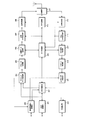
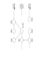
- FIG. 7 is a protocol stack for handling control data of the mobile station apparatus and base station apparatus of EUTRA.
- FIG. 8 is a protocol stack for handling user data of EUTRA mobile station apparatus and base station apparatus. 7 and 8 will be described below.
- the physical layer (Physical layer: PHY layer) provides a transmission service to an upper layer using a physical channel (Physical layer).
- the PHY layer is connected to an upper medium access control layer (Medium Access Control Layer) via a transport channel. Data moves between the MAC layer, the PHY layer, and the layer (layer) via the transport channel. Data transmission / reception is performed between the mobile station apparatus and the base station apparatus via a physical channel.
- Medium Access Control Layer Medium Access Control Layer
- the MAC layer maps various logical channels to various transport channels.
- the MAC layer is connected to an upper radio link control layer (Radio Link Control Layer: RLC layer) through a logical channel.
- the logical channel is roughly classified according to the type of information to be transmitted, and is divided into a control channel for transmitting control information and a traffic channel for transmitting user information.
- the MAC layer has a function to control the PHY layer to perform intermittent reception / intermittent transmission (DRX / DTX), a function to execute a random access procedure, a function to notify transmission power information, a function to perform HARQ control, etc. have.
- the RLC layer divides and concatenates the data received from the upper layer, and adjusts the data size so that the lower layer can transmit data appropriately.
- the RLC layer also has a function for guaranteeing QoS (Quality of Service) required by each data. That is, the RLC layer has functions such as data retransmission control.
- the packet data convergence protocol layer (Packet Data Convergence Protocol layer: PDCP layer) has a header compression function that compresses control information in order to efficiently transmit IP packets as user data in a wireless section.
- the PDCP layer also has a data encryption function.
- the radio resource control layer defines only control information.
- the RRC layer sets and resets a radio bearer (RB) and controls a logical channel, a transport channel, and a physical channel.
- the RB is divided into a signal radio bearer (Signaling Radio Bearer: SRB) and a data radio bearer (Data Radio Bearer: DRB).
- SRB Signal Radio Bearer
- DRB Data Radio Bearer
- the SRB is used as a route for transmitting an RRC message that is control information.
- DRB is used as a route for transmitting user information.
- Each RB is set between the RRC layers of the base station apparatus and the mobile station apparatus.
- the PHY layer corresponds to the physical layer of the first layer in the hierarchical structure of the generally known Open Systems Interconnection (OSI) model
- OSI Open Systems Interconnection
- the MAC layer, RLC layer, and PDCP layer are OSI.
- the RRC layer corresponds to the data link layer, which is the second layer of the model, and the network layer, which is the third layer of the OSI model.
- the random access procedure includes two access procedures: a contention-based random access procedure (Contention based Random Access procedure) and a non-contention based random access procedure (Non-contention based Random Access procedure) (Non-Patent Document 1).
- the contention-based random access procedure is a random access procedure that may collide between mobile station devices, and is being connected to the base station device during initial access from a state in which it is not connected (communication) to the base station device. However, this is performed for a scheduling request or the like when uplink data transmission occurs in the mobile station apparatus in a state where uplink synchronization is lost.
- the non-contention based random access procedure is a random access procedure in which no collision occurs between mobile station devices, and the base station device and the mobile station device are connected but move quickly when the uplink is out of synchronization.
- the mobile station device is instructed by the base station device in a special case such as when handover or the transmission timing of the mobile station device is not effective in order to establish uplink synchronization between the station device and the base station device.
- the non-contention based random access procedure is instructed by an RRC (Radio Resource Control: Layer 3) layer message and physical downlink control channel PDCCH control data.
- RRC Radio Resource Control: Layer 3
- the mobile station device 1-1 transmits a random access preamble to the base station device 3-1 (message 1: (1), step S1).
- the base station device 3-1 that has received the random access preamble transmits a response to the random access preamble (random access response) to the mobile station device 1-1 (message 2: (2), step S2).
- the mobile station device 1-1 transmits an upper layer (Layer2 / Layer3) message based on the scheduling information included in the random access response (message 3: (3), step S3).
- the base station device 3-1 transmits a collision confirmation message to the mobile station device 1-1 that has received the upper layer message of (3) (message 4: (4), step S4).
- contention-based random access is also referred to as random preamble transmission.
- the base station device 3-1 notifies the mobile station device 1-1 of the preamble number (or sequence number) and the random access channel number to be used (message 0: (1) ', step S11).
- the mobile station apparatus 1-1 transmits the random access preamble having the designated preamble number to the designated random access channel RACH (message 1: (2) ', step S12).
- the base station device 3-1 that has received the random access preamble transmits a response to the random access preamble (random access response) to the mobile station device 1-1 (message 2: (3) ', step S13).
- a contention based random access procedure is performed.
- the non-contention based random access procedure is also referred to as dedicated preamble transmission.
- the scheduling request (SR: Scheduling Request) is explained below.
- the physical uplink control channel PUCCH is a response (ACK / NACK) of downlink data transmitted on the physical downlink shared channel PUSCH, downlink radio channel quality information (Channel Quality Indicator: CQI), and an uplink data transmission request. Used for sending (Scheduling Request).
- the scheduling request is transmitted to the base station apparatus 3-1, using the physical uplink control channel PUCCH allocated from the base station apparatus 3-1. .
- the mobile station apparatus 1-1 After the scheduling request is transmitted, when the physical uplink shared channel PUSCH is allocated from the base station apparatus 3-1, the mobile station apparatus 1-1 transmits the mobile station apparatus 1-1 using the allocated physical uplink shared channel PUSCH. A buffer status report (Buffer Status Report: BSR) indicating data buffer status information is transmitted. The base station device 3-1 performs uplink data scheduling for the mobile station device 1-1 based on the buffer status report.
- BSR Buffer Status Report
- the mobile station apparatus 1-1 After transmitting the scheduling request, when the physical uplink shared channel PUSCH cannot be allocated from the base station apparatus 3-1, the mobile station apparatus 1-1 transmits the scheduling request again. If the physical uplink shared channel PUSCH cannot be allocated from the base station apparatus 3-1 even after repeating retransmission of the scheduling request, the mobile station apparatus 1-1 transmits the allocated physical uplink control channel PUCCH and uplink reference signal. Random access procedure for scheduling request is executed. Note that in the scheduling request based on the random access procedure, the mobile station apparatus 1-1 transmits a buffer status report by transmitting the message 3.
- the MAC layer has a function of mapping each logical channel to a transport channel. This procedure is called a logical channel prioritization (LCP) procedure.
- LCP logical channel prioritization
- the basic LCP procedure takes into account the priority of each logical channel and the transmission bit rate (Prioritized Bit Rate: PBR) that must be transmitted within a certain period corresponding to the QoS of the radio bearer.
- PBR Transmission Bit Rate
- the priority order is determined, and the data having the higher transmission priority at the time when the uplink grant is received is mapped to the transport channel.
- the MAC layer acquires information such as the logical channel number of each RB, the priority of the logical channel, and the PBR from the RRC layer.
- the MAC layer has a function of notifying the data amount of the transmission buffer corresponding to each logical channel. This function is called buffer status report (Buffer Status Report: BSR).
- BSR buffer Status Report
- each logical channel is assigned to a logical channel group (Logical Channel Group: LCG), and the transmission buffer amount for each LCG is notified to the base station apparatus as a MAC layer message.
- LCG Logical Channel Group
- BSR includes a Short BSR that reports the buffer status of one logical channel group and a Long BSR that reports the buffer status of multiple logical channel groups.
- the MAC layer transmits a scheduling request (SR) to the PHY layer.
- SR scheduling request
- the MAC layer transmits the BSR after radio resources are allocated.
- the PHY layer transmits the scheduling request using the physical uplink control channel PUCCH.
- the MAC layer instructs the PHY layer to make a scheduling request using the physical random access channel PRACH when the physical uplink control channel PUCCH for scheduling request transmission is not assigned (not valid). .
- Advanced-EUTRA a further evolution of EUTRA.
- communication at a maximum transmission rate of 1 Gbps or higher and 500 Mbps or higher of the uplink is performed using a band up to a maximum of 100 MHz bandwidth in the uplink and the downlink, respectively.
- Advanced-EUTRA is considering to realize a maximum of 100 MHz band by bundling a plurality of bands below 20 MHz of EUTRA so that EUTRA mobile station devices can be accommodated.
- one band below 20 MHz of EUTRA is called a component carrier (Component (Carrier: CC).
- Component (Carrier: CC) is called a component carrier (Component (Carrier: CC).
- CC component carrier
- one cell is configured by combining one downlink component carrier and one uplink component carrier.
- a single cell can be configured with only one downlink component carrier.
- the base station apparatus allocates a plurality of cells that match the communication capability and communication conditions of the mobile station apparatus, and communicates with the mobile station apparatus via the allocated plurality of cells.
- the some cell allocated to the mobile station apparatus is classified into a 1st cell (Primary Cell: PCell) and a cell other than that as a 2nd cell (Secondary Cell: SCell).
- a special function such as allocation of the physical uplink control channel PUCCH is set in the first cell.
- the mobile station apparatus does not perform downlink reception processing for the second cell immediately after allocation (or the radio resource indicated by the physical downlink control channel PDCCH). After not instructing activation (Activate or activation (activation)) from the base station device, start the downlink reception process for the second cell instructed to activate (or According to the radio resource allocation information indicated by the physical downlink control channel PDCCH).
- the mobile station apparatus is instructed to deactivate the second cell activated from the base station apparatus, and is then directed to the second cell instructed to be deactivated.
- the downlink reception process is stopped (or the radio resource allocation information indicated by the physical downlink control channel PDCCH is not followed).
- the second cell that is instructed to be activated by the base station device and is performing downlink reception processing is called an activated cell, and the second cell immediately after the allocation from the base station device to the mobile station device, and the deactivation
- the second cell that has been instructed to stop the downlink reception process is called a deactivated cell.
- the first cell is always an activated cell.
- the MAC layer of the mobile station device performs control of the PHY layer in order to manage the PHY layer to perform cell activation / deactivation and uplink transmission timing when performing carrier aggregation. Has the ability to do.
- the mobile station apparatus performs dual connection with two base station apparatuses and simultaneously connects to both base station apparatuses.
- Dual connect is not a high-speed backbone line (also referred to as a backhaul) that can be regarded as non-delayed like an optical fiber between a macro cell base station apparatus and a small cell base station apparatus, but uses a low-speed backbone line with a delay.
- the mobile station device is connected to the macro cell base station device and the small cell base station device, and the mobile station device and both base station devices transmit and receive data via a plurality of cells. This is assumed (Non-Patent Document 2).
- control data is transmitted and received between the macro cell base station apparatus and the mobile station apparatus
- user data is transmitted and received between the small cell base station apparatus and the mobile station apparatus.
- the base station apparatus that transmits and receives data based on the type of data (for example, QoS or logical channel). For example, the same data radio bearer data is transmitted from a different base station device of the macro cell base station device and the small cell base station device to the mobile station device, and the same data radio bearer data is transmitted from the mobile station device to the macro cell base. It is considered to transmit to a different base station device between the station device and the small cell base station device.
- the same data radio bearer data is transmitted from a different base station device of the macro cell base station device and the small cell base station device to the mobile station device, and the same data radio bearer data is transmitted from the mobile station device to the macro cell base. It is considered to transmit to a different base station device between the station device and the small cell base station device.
- At least control information (Control-plane information) of the mobile station apparatus 1-1 is transmitted / received between the base station apparatus 3-1 of the macro cell and the MME (Mobility Management Entity).
- At least user information (User-plane information) of the mobile station device 1-1 is transmitted and received between the small cell base station device 3-2 and the GW (Gateway).
- Control information for controlling the mobile station apparatus 1-1 is transmitted and received between the macro cell base station apparatus 3-1 and the small cell base station apparatus 3-2.
- At least control information is transmitted and received between the base station apparatus 3-1 and the mobile station apparatus 1-1 in the macro cell.
- the user information is transmitted and received between the small cell base station apparatus 3-2 and the mobile station apparatus 1-1. Note that user information may be transmitted and received between the macro cell base station apparatus 3-1 and the mobile station apparatus 1-1.
- At least control information (Control-plane information) of the mobile station apparatus 1-1 is transmitted and received between the base station apparatus 3-1 and MME (Mobility Management Entity) of the macro cell. Done. At least user information (User-plane information) of the mobile station apparatus 1-1 is transmitted and received between the base station apparatus 3-1 and GW (Gateway) in the macro cell.
- MME Mobility Management Entity
- User-plane information is transmitted and received between the base station apparatus 3-1 and GW (Gateway) in the macro cell.
- the macro cell base station apparatus 3-1 transfers the user information received from the GW to the small cell base station apparatus 3-2.
- the small cell base station apparatus 3-2 transfers the user information received from the mobile station apparatus 1-1 to the base station apparatus 3-1.
- transmission / reception of control information for controlling the mobile station apparatus 1-1 is performed between the base station apparatus 3-1 of the macro cell and the base station apparatus 3-2 of the small cell.
- Control information or user information is transmitted and received between the macro cell base station apparatus 3-1 and the mobile station apparatus 1-1.
- the user information is transmitted and received between the small cell base station apparatus 3-2 and the mobile station apparatus 1-1.
- bearer division (Bearer) in which information of the same radio bearer (Radio ⁇ ⁇ ⁇ Bearer: RB) is transmitted and received between the mobile station apparatus and both base station apparatuses via both the macro cell and the small cell. Split) is performed.
- the MAC layer of the mobile station device also has a function of controlling the PHY layer in order to manage transmission timing groups.
- FIG. 1 is a diagram illustrating a configuration of a mobile station apparatus according to an embodiment of the present invention.
- the mobile station apparatuses 1-1 to 1-3 include an uplink data processing unit 101, an uplink control unit 103-1, an uplink control unit 103-2, a transmission data storage unit 105-1, and a transmission data storage unit 105-2.
- the uplink data processing unit 101 has a PDCP layer function.
- the uplink data processing unit 101 performs processing such as header compression of user data IP packets, data encryption, data division and combination, and adjusts the data size.
- the uplink data processing unit 101 outputs the processed data to the uplink control unit 103-1 or the uplink control unit 103-2.
- the uplink data processing unit 101 may output data to the uplink control unit 103-1 or the uplink control unit 103-2 in accordance with an instruction from the base station device 3-1. Further, the uplink data processing unit 101 considers the amount of data stored in the transmission data storage unit 105-1 and the transmission data storage unit 105-2, or downlink radio channel quality information, etc. The data may be output to 103-1 or the uplink control unit 103-2.
- the uplink control unit 103-1 or the uplink control unit 103-2 has a function of the RLC layer.
- the uplink control unit 103-1 or the uplink control unit 103-2 performs processing such as data division and combination on the data input from the uplink data processing unit 101, and adjusts the data size. Also, the uplink control unit 103-1 or the uplink control unit 103-2 performs retransmission control on specific data.
- Uplink control section 103-1 or uplink control section 103-2 outputs the processed data to transmission data storage section 105-1 or transmission data storage section 105-2.
- the transmission data storage unit 105-1 accumulates (buffers) the data of each logical channel input from the uplink control unit 103-1, and is instructed by the specified data based on the instruction from the MAC control unit 125. Only the data amount is output to the transmission HARQ processing unit 107-1. In addition, the transmission data storage unit 105-1 outputs information on the amount of data accumulated based on an instruction from the MAC control unit 125 to the MAC control unit 125.
- the transmission data storage unit 105-1 indicates that new data has been generated in the MAC control unit 125 when new logical channel data is input from the uplink control unit 103-1 in a state where there is no logical channel data. Notice. Also, the transmission data storage unit 105-1 receives priority from the uplink control unit 103-1 when the logical channel data having a higher priority than the accumulated logical channel data is input from the uplink control unit 103-1. Notify that high data has occurred. Similar to the transmission data storage unit 105-1, the transmission data storage unit 105-2 processes the data input from the uplink control unit 103-2.
- the transmission HARQ processing unit 107-1 encodes input data from the transmission data storage unit 105-1, and performs puncture processing on the encoded data. Then, transmission HARQ processing section 107-1 outputs the punctured data to transmission processing section 109-1, and stores the encoded data.
- the transmission HARQ processing unit 107-1 when instructed to retransmit data from the MAC control unit 125, performs a puncture process different from the previously performed puncture from the stored encoded data, and transmits the punctured data. Output to the unit 109-1. Similar to transmission HARQ processing section 107-1, transmission HARQ processing section 107-2 processes the data input from transmission data storage section 105-2 and outputs it to transmission processing section 109-2.
- the transmission processing unit 109-1 modulates and encodes the data input from the transmission HARQ processing unit 107-1.
- the transmission processing unit 109-1 performs DFT (Discrete Fourier Transform (Discrete Fourier Transform))-IFFT (Inverse Fast Fourier Transform) processing on the modulated and encoded data, and after processing, CP (Cyclic prefix) is inserted, and the data after CP insertion is placed on the physical uplink shared channel (PUSCH) of each uplink component carrier (or cell) and output to the radio section 111-1.
- DFT Discrete Fourier Transform
- IFFT Inverse Fast Fourier Transform
- the transmission processing unit 109-1 generates an ACK or NACK signal when receiving a response to the received data from the PHY control unit 123, and uses the generated signal as the physical component of each uplink component carrier (or cell). It arrange
- the transmission processing unit 109-1 When receiving a scheduling request transmission instruction from the PHY control unit 123, the transmission processing unit 109-1 generates a scheduling request signal, and the generated signal is used for physical uplink control of each uplink component carrier (or cell). It arranges on the channel (PUCCH) and outputs it to the radio section 111-1.
- the transmission processing unit 109-1 When there is a random access preamble transmission instruction from the PHY control unit 123, the transmission processing unit 109-1 generates a random access preamble, places the generated signal in the physical random access channel (PRACH), and transmits the radio unit 111- Output to 1. Similarly to the transmission processing unit 109-1, the transmission processing unit 109-2 processes the data input from the transmission HARQ processing unit 107-2 and outputs the processed data to the radio unit 111-2.
- PRACH physical random access channel
- Radio section 111-1 up-converts the data input from transmission processing section 109-1 to the radio frequency of transmission position information (transmission cell information) instructed by PHY control section 123, adjusts the transmission power, and transmits Send data from the antenna. Radio section 111-1 down-converts the radio signal received from the reception antenna and outputs the result to reception processing section 113-1.
- the radio unit 111-2 up-converts the data input from the transmission processing unit 109-2 to the radio frequency of the transmission location information (transmission cell information) instructed by the PHY control unit 123, and adjusts the transmission power. To transmit data from the transmitting antenna. Radio section 111-2 down-converts the radio signal received from the reception antenna and outputs the result to reception processing section 113-2. Note that the frequencies controlled by the radio unit 111-1 and the radio unit 111-2 may be the same frequency band or different frequency bands.
- the reception processing unit 113-1 performs FFT (Fast Fourier ⁇ Transform) processing, decoding, demodulation processing, and the like on the signal input from the wireless unit 111-1.
- Reception processing section 113-1 outputs physical downlink shared channel (PDSCH) data among the demodulated data to reception HARQ processing section 115-1.
- the reception processing unit 113-1 includes the uplink transmission data response information (ACK / NACK) and uplink transmission permission information (Uplink grant: control data) acquired from the physical downlink control channel PDCCH among the demodulated data. Uplink grant) is output to the MAC control unit 125.
- FFT Fast Fourier ⁇ Transform
- the uplink transmission permission information includes transmission position information of uplink radio resources (physical uplink shared channel), data modulation / coding scheme, data size information, HARQ information, and the like. Further, the reception processing unit 113-1 measures the downlink reference signal, and measures the downlink radio channel quality between the base station device 3-1 and the mobile station device 1-1. Similarly to the reception processing unit 113-1, the reception processing unit 113-2 processes the data input from the radio unit 111-2, and outputs the processed data to the reception HARQ processing unit 115-2.
- the reception HARQ processing unit 115-1 performs a decoding process on the input data from the reception processing unit 113-1, and outputs the data to the MAC information extraction unit 117-1 when the decoding process is successful.
- the reception HARQ processing unit 115-1 stores the data that has failed in the decoding process when the input data decoding process has failed.
- the reception HARQ processing unit 115-1 When receiving the retransmission data, the reception HARQ processing unit 115-1 combines the stored data and the retransmission data, and performs a decoding process.
- reception HARQ processing unit 115-1 notifies the MAC control unit 125 of success or failure of the input data decoding process.
- reception HARQ processing section 115-2 processes the data input from reception processing section 113-2, and outputs the processed data to MAC information extraction section 117-2.
- the MAC information extraction unit 117-1 extracts the control data of the MAC layer (Medium Access Access Control layer) from the data input from the reception HARQ processing unit 115-1, and outputs the extracted control information to the MAC control unit 125.
- the MAC information extraction unit 117-1 outputs the remaining data to the downlink control unit 119-1.
- the MAC information extraction unit 117-2 processes the data input from the reception HARQ processing unit 115-2, and outputs the processed data to the downlink control unit 119-2. .
- the downlink control unit 119-1 has an RLC layer function, and performs processing such as division and combination of data input from the MAC information extraction unit 117-1.
- the downlink control unit 119-1 outputs the processed data to the downlink data processing unit 121.
- the downlink control unit 119-2 processes the data input from the MAC information extraction unit 117-1 and outputs the processed data to the downlink data processing unit 121. .
- the downlink data processing unit 121 has a PDCP layer function, and performs processing such as decompression (decompression) of a compressed IP header, decryption of encrypted data, and data division and combination.
- the downlink data processing unit 121 divides the RRC message into user data, outputs the RRC message to the RRC control unit 127, and outputs the user data to the upper layer.
- the PHY control unit 123 receives a transmission processing unit 109-1, a transmission processing unit 109-2, a wireless unit 111-1, a wireless unit 111-2, a reception processing unit 113-1, and a reception processing unit according to instructions from the MAC control unit 125. 113-2 is controlled.
- the PHY control unit 123 transmits the modulation / coding method and transmission position from the modulation / coding method, transmission power information and transmission position information (transmission cell information) notified from the MAC control unit 125 to the transmission processing unit 109-1 or transmission.
- the processor 109-2 is notified, and the frequency information and transmission power information of the transmission cell are notified to the radio unit 111-1 or the radio unit 111-2.
- the MAC control unit 125 includes the data control setting designated from the RRC control unit 127 and the data amount information acquired from the transmission data storage unit 105-1 or the transmission data storage unit 105-2 and the reception processing unit 113-1 or the reception processing unit. Based on the uplink transmission permission information acquired from 113-2, the data transmission destination and the data transmission priority are determined, and the transmission data storage unit 105-1 or the transmission data storage unit 105-2 is notified of the information regarding the data to be transmitted. To do. Further, the MAC control unit 125 notifies the HARQ information to the transmission HARQ processing unit 107-1 or the transmission HARQ processing unit 107-2, and outputs the modulation / coding scheme and transmission position information to the PHY control unit 123.
- the MAC control unit 125 triggers a buffer status report when notified of a change in the data accumulation state from the transmission data storage unit 103-1 or the transmission data storage unit 103-2.
- the MAC control unit 125 acquires the uplink transmission permission information from the reception processing unit 113-1 or the reception processing unit 113-2 while the buffer status report is triggered, the MAC control unit 125 stores the information on each logical channel in the transmission data storage unit 103. Instruct to report the amount of data accumulated.
- the MAC control unit 125 acquires information on the accumulated amount of data of each logical channel from the transmission data storage unit 105-1 or the transmission data storage unit 105-2, it creates a buffer status report and transmits the created buffer status report. The data is output to the data storage unit 105-1 or the transmission data storage unit 105-2.
- the MAC control unit 125 determines transmission of the scheduling request and instructs the PHY control unit 123 to transmit the scheduling request.
- the MAC control unit 125 creates a buffer status report, and transmits the created buffer status report to the transmission / reception data storage unit 105-1 or the transmission data storage unit 105-2. Output to.
- the MAC control unit 125 counts the number of transmissions of the scheduling request, and instructs the PHY control unit 123 to perform random access preamble transmission when the uplink transmission permission information is not acquired even when the number of transmissions of the scheduling request reaches the maximum number of transmissions. To do. Further, the MAC control unit 125 notifies the RRC control unit 127 of the release of uplink radio resources allocated to the own mobile station device.
- the MAC control unit 125 acquires response information for the uplink transmission data from the reception processing unit 113-1 or the reception processing unit 113-2, and when the response information indicates NACK (non-response), the transmission HARQ processing unit 107 -1 or the transmission HARQ processing unit 107-2 and the PHY control unit 123 are instructed to perform retransmission.
- the MAC control unit 125 instructs the PHY control unit 123 to transmit an ACK or NACK signal when the success / failure information of the data decoding process is acquired from the reception HARQ processing unit 115-1 or the reception HARQ processing unit 115-2. .
- the MAC control unit 125 has a MAC layer function and activates a cell (or component carrier) in the MAC control information input from the MAC information extraction unit 117-1 or the MAC information extraction unit 117-2.
- / Deactivation instruction information and discontinuous reception (DRX) control information, the radio unit 111-1 or the radio unit 111-2, the transmission processing unit 109-1 or the transmission processing unit 109-1 or the like for activation / deactivation control and DRX control Instructs the PHY control unit 123 to control the transmission processing unit 109-2 and the reception processing unit 113-1 or the reception processing unit 113-2.
- the MAC control unit 125 manages the validity / invalidity of uplink transmission timing using a transmission timing timer.
- the MAC control unit 125 has a transmission timing timer for each cell or transmission timing group, and starts or restarts a transmission timing timer corresponding to the case where transmission timing information is applied for each cell or transmission timing group.
- the transmission timing timer expires, the MAC control unit 125 stops uplink transmission for the cell whose transmission timing timer has expired.
- the MAC control unit 125 outputs the transmission timing information to the PHY control unit 123 among the MAC control information input from the MAC information extraction unit 117-1 or the MAC information extraction unit 117-2.
- the MAC control unit 125 manages uplink transmission timing and controls the PHY control unit 123.
- the RRC control unit 127 is connected to the base station device 3-1 and the base station device 3-2 such as RRC connection and connection release processing with the base station device 3-1, carrier aggregation setting, control data and data control setting of user data, etc. Make various settings for communication.
- the RRC control unit 127 exchanges information with an upper layer associated with various settings, and controls a lower layer associated with various settings.
- the RRC control unit 127 manages radio resources of each cell allocated from the base station device 3-1.
- the RRC control unit 127 creates an RRC message and outputs the created RRC message to the uplink data processing unit 101.
- the RRC control unit 127 analyzes the RRC message input from the downlink data processing unit 121.
- the RRC control unit 127 outputs information necessary for the MAC layer to the MAC control unit 125, and outputs information necessary for the physical layer to the PHY control unit 123.
- the RRC control unit 127 includes the logical channel of each data, the priority of the logical channel of each data, information indicating the relationship between the logical channel of each control data and the logical channel group, the base station apparatus (or cell, cell group) and the logical
- data control setting information such as relationship information with a channel
- the data transmission control setting information is output to the MAC control unit 125.
- the RRC control unit 127 recognizes that the base station device 3-1 and the base station device 3-2 communicate with each other through dual connection, the RRC control unit 127 notifies the MAC control unit 125 that the dual connection state is established.
- the RRC control unit 127 When the RRC control unit 127 is notified of the release of the uplink radio resource from the MAC layer, the RRC control unit 127 releases the uplink radio resource such as the physical uplink control channel PUCCH and the uplink reference signal assigned to the target cell. To do.
- the transmission processing unit 109-1, the transmission processing unit 109-2, the wireless unit 111-1, the wireless unit 111-2, the reception processing unit 113-1, the reception processing unit 113-2, and the PHY control unit 123 Perform the operation.
- the extraction unit 117-1, the MAC information extraction unit 117-2, and the MAC control unit 125 perform the operation of the MAC layer.
- the uplink control unit 103-1, the uplink control unit 103-2, the downlink control unit 119-1 and the downlink control unit 119-2 perform the operation of the RLC layer.
- the uplink data processing unit 101 and the downlink data processing unit 121 perform the PDCP layer operation, and the RRC control unit 127 performs the RRC layer operation.
- uplink control section 103-1 transmission data storage section 105-1, transmission HARQ processing section 107-1, transmission processing section 109-1 and radio section 111-1 perform transmission operations to base station apparatus 3-1.
- the uplink control unit 103-2, the transmission data storage unit 105-2, the transmission HARQ processing unit 107-2, the transmission processing unit 109-2, and the radio unit 111-2 perform a transmission operation to the base station apparatus 3-1.
- the downlink control unit 119-1, the MAC information extraction unit 117-1, the reception HARQ processing unit 115-1, the reception processing unit 113-1 and the radio unit 111-1 perform a reception operation on the base station device 3-1
- the link control unit 119-2, the MAC information extraction unit 117-2, the reception HARQ processing unit 115-2, the reception processing unit 113-2, and the radio unit 111-2 perform a reception operation on the base station apparatus 3-2.
- FIG. 2 is a diagram showing a configuration of the base station apparatus according to the embodiment of the present invention.
- the base station apparatus 3-1 includes a downlink data processing unit 201, a downlink control unit 203, a transmission data storage unit 205, a transmission HARQ processing unit 207, a transmission processing unit 209, a radio unit 211, a reception processing unit 213, and a reception HARQ process.
- the downlink data processing unit 201 has a PDCP layer function.
- the downlink data processing unit 201 performs processing such as header compression of the IP packet of user data, data encryption, data division and combination, and adjusts the data size.
- the downlink data processing unit 201 outputs the processed data to the downlink control unit 203 or the inter-base station communication unit 229.
- the downlink data processing unit 201 applies downlink radio channel quality information, the amount of downlink data for the mobile station apparatus 1-1, and all the mobile station apparatuses of the base station apparatus 3-1 or the base station apparatus 3-2. In consideration of at least one of the transmission data amount (traffic amount), the data is output to the downlink control unit 203 or the inter-base station communication unit 229.
- the downlink control unit 203 has an RLC layer function.
- the downlink control unit 203 performs processing such as data division and combination on the data input from the downlink data processing unit 201 and adjusts the data size. Further, the downlink control unit 203 performs retransmission control on specific data.
- the downlink control unit 203 outputs the processed data to the transmission data storage unit 205.
- the transmission data storage unit 205 accumulates the data input from the downlink control unit 203 for each user, and transmits the user data instructed based on the instruction from the MAC control unit 225 by the specified data amount. The data is output to the processing unit 207. In addition, the transmission data storage unit 205 outputs information on the amount of accumulated data to the MAC control unit 225.
- the transmission HARQ processing unit 207 performs encoding on the input data and performs puncture processing on the encoded data. Then, transmission HARQ processing section 207 outputs the punctured data to transmission processing section 209 and stores the encoded data.
- the transmission HARQ processing unit 207 is instructed to retransmit data from the MAC control unit 225, the transmission HARQ processing unit 207 performs puncture processing different from the previously performed puncture from the stored encoded data, and transmits the punctured data to the transmission processing unit 209. Output to.
- the transmission processing unit 209 modulates and encodes the data input from the transmission HARQ processing unit 207.
- the transmission processing unit 209 maps the modulated and encoded data to signals such as physical downlink control channel PDCCH, downlink synchronization signal, physical broadcast channel PBCH, physical downlink shared channel PDSCH and the like of each cell,
- the mapped data is subjected to OFDM signal processing such as serial / parallel conversion, IFFT (Inverse Fourier Transform (Inverse Fast Fourier Transform)) conversion, and CP insertion to generate an OFDM signal.
- OFDM signal processing such as serial / parallel conversion, IFFT (Inverse Fourier Transform (Inverse Fast Fourier Transform)) conversion, and CP insertion to generate an OFDM signal.
- the transmission processing unit 209 outputs the generated OFDM signal to the wireless unit 211. Further, when there is an instruction to respond to received data from the MAC control unit 225, the transmission processing unit 209 generates an ACK or NACK signal, places the generated signal on the physical downlink control channel PDCCH, and outputs it to the radio unit 211 To do. The transmission processing unit 209 places the uplink transmission permission information notified from the PHY control unit 223 on the physical downlink control channel PDCCH, and outputs the information to the radio unit 211.
- the radio unit 211 up-converts data input from the transmission processing unit 209 to a radio frequency, adjusts transmission power, and transmits data from the transmission antenna. Further, the radio unit 211 down-converts the radio signal received from the reception antenna and outputs it to the reception processing unit 213.
- the reception processing unit 213 performs FFT (Fast Fourier Transform) processing, decoding, demodulation processing, and the like on the signal input from the wireless unit 211.
- the reception processing unit 213 outputs the physical uplink shared channel (PUSCH) data to the reception HARQ processing unit 215 among the demodulated data.
- the reception processing unit 213 receives response information (ACK / NACK) of downlink transmission data, downlink radio channel quality information (CQI), and uplink of control data acquired from the physical uplink control channel PUCCH among the demodulated data.
- the link transmission request information (scheduling request) is output to the MAC control unit 225.
- the reception processing unit 213 measures an uplink reference signal to measure the uplink radio channel quality between the base station device 3-1 and the mobile station device 1-1.
- the reception HARQ processing unit 215 performs a decoding process on the input data from the reception processing unit 213, and outputs the data to the MAC information extraction unit 217 when the decoding process is successful.
- the reception HARQ processing unit 215 stores the data that has failed in the decoding process when the decoding process of the input data has failed.
- the reception HARQ processing unit 215 When receiving the retransmission data, the reception HARQ processing unit 215 combines the stored data and the retransmission data and performs a decoding process. Also, the reception HARQ processing unit 215 notifies the MAC control unit 225 of the success or failure of the input data decoding process.
- the MAC information extraction unit 217 extracts MAC layer control data from the data input from the reception HARQ processing unit 215, and outputs the extracted control data to the MAC control unit 225.
- the MAC information extraction unit 217 outputs the remaining data to the uplink control unit 219.
- the MAC layer control data includes a buffer status report.
- the uplink control unit 219 has an RLC layer function.
- the uplink control unit 219 performs processing such as data division and combination on the data input from the MAC information extraction unit 217, and adjusts the data size. Also, the uplink control unit 219 performs retransmission control for specific data.
- the uplink control unit 219 outputs the processed data to the uplink data processing unit 221.
- the uplink data processing unit 221 has a PDCP layer function.
- the uplink data processing unit 221 performs processing such as a decompression (decompression) function of a compressed IP header, a decryption function of encrypted data, and data division and combination.
- the uplink data processing unit 221 divides the RRC message and user data, outputs the RRC message to the RRC control unit 227, and outputs the user data to the GW communication unit 233.
- the PHY control unit 223 controls the transmission processing unit 209, the radio unit 211, and the reception processing unit 213 according to an instruction from the MAC control unit 225.
- the PHY control unit 223 creates uplink transmission permission information from the uplink scheduling result notified from the MAC control unit 225 and notifies the transmission processing unit 209 of the uplink transmission permission information.
- the MAC control unit 225 has a MAC layer function.
- the MAC control unit 225 controls the MAC layer based on information acquired from the RRC control unit 227 and lower layers.
- the MAC control unit 225 performs scheduling processing of data transmitted on the downlink and uplink.
- the MAC control unit 225 receives downlink transmission data response information (ACK / NACK), downlink radio channel quality information (CQI) input from the reception processing unit 213, and each user acquired from the transmission data storage unit 205.
- a downlink data scheduling process is performed from the data amount information.
- the MAC control unit 225 controls the transmission data storage unit 205, the transmission HARQ processing unit 207, and the transmission processing unit 209 based on the result of the scheduling process.
- the MAC control unit 225 performs uplink data scheduling processing from the uplink transmission request information (scheduling request) input from the reception processing unit 213 and the buffer status report input from the MAC information extraction unit 217.
- the MAC control unit 225 notifies the PHY control unit 223 of the result of the scheduling process.
- the MAC control unit 225 acquires response information for the uplink transmission data from the reception processing unit 213, and resends to the transmission HARQ processing unit 207 and the transmission processing unit 209 when the response information indicates NACK (non-response). Instruct.
- the MAC control unit 225 instructs the transmission processing unit 209 to transmit an ACK or NACK signal.
- the MAC control unit 225 performs activation / deactivation processing of the cell (or component carrier) assigned to the mobile station device 1-1.
- the MAC control unit 225 manages transmission timing groups and uplink transmission timing of each transmission timing group.
- the RRC control unit 227 performs RRC connection and connection release processing with the mobile station device 1-1, carrier aggregation setting, dual connect setting, and control cell and user data of the mobile station device 1-1 at which cell ( Alternatively, various settings for communication with the mobile station apparatus 1-1 such as data control settings for transmission / reception with the base station apparatus) are performed, information is exchanged with the higher layer according to the various settings, and the various settings are performed. Control the lower layers.
- the RRC control unit 227 creates various RRC messages and outputs the created RRC messages to the downlink data processing unit 201.
- the RRC control unit 227 analyzes the RRC message input from the uplink data processing unit 221.
- the RRC control unit 227 outputs information necessary for the MAC layer to the MAC control unit 225, and outputs information necessary for the physical layer to the PHY control unit 223. Also, the RRC control unit 227 notifies the necessary information to the inter-base station communication unit 229 and the MME communication unit 231 when performing handover or dual connection.
- the inter-base station apparatus communication unit 229 connects to another base station apparatus (base station apparatus 3-2) and transmits a control message between the base station apparatuses input from the RRC control unit 227 to the other base station apparatus. .
- the inter-base station apparatus communication unit 229 receives control messages between base station apparatuses from other base station apparatuses, and outputs the received control messages to the RRC control unit 227.
- Control messages between base station devices include messages related to handover, control messages related to connection and release of dual connect, messages related to data control of the mobile station device 1-1, and the like.
- the inter-base station apparatus communication unit 229 transmits the downlink user data of the mobile station apparatus 1-1 that is dual-connected to another base station apparatus.
- the inter-base station communication unit 229 receives uplink user data of the mobile station apparatus 1-1 that is dual-connected from another base station apparatus, and outputs the received data to the data uplink data processing unit 221.
- the MME communication unit 231 is connected to an MME (Mobility Management Entity), and transmits a control message (S1 message) between the base station apparatus and the MME input from the RRC control unit 227 to the MME. Also, the MME communication unit 231 receives a control message between the base station apparatus and the MME from the MME, and outputs the received control message to the RRC control unit 227. Control messages between the base station apparatus and the MME include a path switch request message and a path switch request response message.
- the inter-GW communication unit 233 is connected to the GW (Gateway), receives the user data of the mobile station device 1-1 sent from the GW, and outputs the received data to the downlink data processing unit 201. In addition, the inter-GW communication unit 233 transmits the user data of the mobile station device 1-1 input from the uplink data processing unit 221 to the GW.
- the transmission processing unit 209, the radio unit 211, and the reception processing unit 213 operate in the PHY layer, and transmit data storage unit 205, transmission HARQ processing unit 207, reception HARQ processing unit 215, MAC information extraction unit 217, MAC control.
- the unit 225 performs the operation of the MAC layer
- the downlink control unit 203 and the uplink control unit 219 perform the operation of the RLC layer
- the downlink data processing unit 201 and the uplink data processing unit 221 perform the operation of the PDCP layer.
- the RRC control unit 227 operates the RRC layer.
- FIG. 3 is a diagram showing a configuration of the base station apparatus according to the embodiment of the present invention.
- the base station apparatus 3-2 includes a downlink control unit 301, a transmission data storage unit 303, a transmission HARQ processing unit 305, a transmission processing unit 307, a radio unit 309, a reception processing unit 311, a reception HARQ processing unit 313, and a MAC information extraction unit. 315, an uplink control unit 317, a PHY control unit 319, a MAC control unit 321, an RRC control unit 323, an inter-base station communication unit 325, and an MME communication unit 327.
- the downlink control unit 301 has an RLC layer function, and performs processing such as data division and combination on the data input from the inter-base station communication unit 325 to adjust the data size. Further, the downlink control unit 301 performs retransmission control on specific data. The downlink control unit 301 outputs the processed data to the transmission data storage unit 303.
- the transmission data storage unit 303 accumulates the data input from the downlink control unit 301 for each user, and transmits the user data instructed based on the instruction from the MAC control unit 321 by the specified data amount. The data is output to the processing unit 305. In addition, the transmission data storage unit 303 outputs information on the amount of accumulated data to the MAC control unit 321.
- the transmission HARQ processing unit 305 encodes input data and performs puncture processing on the encoded data. Then, the transmission HARQ processing unit 305 outputs the punctured data to the transmission processing unit 307, and stores the encoded data. When the transmission HARQ processing unit 305 is instructed to retransmit the data from the MAC control unit 321, the transmission HARQ processing unit 305 performs puncture processing different from the previously performed puncture from the stored encoded data, and transmits the punctured data to the transmission processing unit 307. Output to.
- the transmission processing unit 307 modulates and encodes the data input from the transmission HARQ processing unit 305.
- the transmission processing unit 307 maps the modulated and encoded data to signals such as physical downlink control channel PDCCH, downlink synchronization signal, physical broadcast channel PBCH, physical downlink shared channel PDSCH and the like of each cell,
- the mapped data is subjected to OFDM signal processing such as serial / parallel conversion, IFFT (Inverse Fourier Transform (Inverse Fast Fourier Transform)) conversion, and CP insertion to generate an OFDM signal.
- OFDM signal processing such as serial / parallel conversion, IFFT (Inverse Fourier Transform (Inverse Fast Fourier Transform)) conversion, and CP insertion to generate an OFDM signal.
- the transmission processing unit 307 outputs the generated OFDM signal to the wireless unit 309.
- the transmission processing unit 307 when there is a response instruction for received data from the MAC control unit 321, the transmission processing unit 307 generates an ACK or NACK signal, places the generated signal in the physical downlink control channel PDCCH, and outputs it to the radio unit 309. To do.
- the transmission processing unit 307 arranges the uplink transmission permission information notified from the PHY control unit 319 in the physical downlink control channel PDCCH and outputs it to the radio unit 309.
- the radio unit 309 up-converts data input from the transmission processing unit 307 to a radio frequency, adjusts transmission power, and transmits data from the transmission antenna.
- the radio unit 309 down-converts the radio signal received from the reception antenna and outputs it to the reception processing unit 311.
- the reception processing unit 311 performs FFT (Fast Fourier Transform) processing, decoding, demodulation processing, and the like on the signal input from the wireless unit 309.
- the reception processing unit 311 outputs the physical uplink shared channel (PUSCH) data to the reception HARQ processing unit 313 among the demodulated data.
- the reception processing unit 311 includes, in the demodulated data, response information (ACK / NACK) of downlink transmission data of control data acquired from the physical uplink control channel PUCCH, downlink radio channel quality information (CQI), and uplink
- the link transmission request information (scheduling request) is output to the MAC control unit 321.
- the reception processing unit 313 measures the uplink reference signal, and measures the uplink radio channel quality between the base station device 3-2 and the mobile station device 1-1.
- the reception HARQ processing unit 313 performs a decoding process on the input data from the reception processing unit 311, and outputs the data to the MAC information extraction unit 315 when the decoding process is successful.
- the reception HARQ processing unit 313 stores the data that has failed in the decoding process when the decoding process of the input data has failed.
- the reception HARQ processing unit 313 When receiving the retransmission data, the reception HARQ processing unit 313 combines the stored data and the retransmission data and performs a decoding process.
- the reception HARQ processing unit 313 notifies the MAC control unit 321 of the success or failure of the input data decoding process.
- the MAC information extraction unit 315 extracts MAC layer control data from the data input from the reception HARQ processing unit 313, and outputs the extracted control data to the MAC control unit 321.
- the MAC information extraction unit 315 outputs the remaining data to the uplink control unit 317.
- the MAC layer control data includes a buffer status report.
- the uplink control unit 317 has an RLC layer function.
- the uplink control unit 317 performs processing such as data division and combination on the data input from the MAC information extraction unit 315, and adjusts the data size. Further, the uplink control unit 317 performs retransmission control on specific data.
- the uplink control unit 317 outputs the processed data to the inter-base station communication unit 325.
- the PHY control unit 319 controls the transmission processing unit 307, the wireless unit 309, and the reception processing unit 311 according to an instruction from the MAC control unit 321.
- the PHY control unit 319 creates uplink transmission permission information from the uplink scheduling result notified from the MAC control unit 321 and notifies the transmission processing unit 307 of it.
- the MAC control unit 321 has a MAC layer function.
- the MAC control unit 321 controls the MAC layer based on information acquired from the RRC control unit 323 and lower layers.
- the MAC control unit 321 performs scheduling processing of data transmitted on the downlink and uplink.
- the MAC control unit 321 receives downlink transmission data response information (ACK / NACK), downlink radio channel quality information (CQI) input from the reception processing unit 311, and each user acquired from the transmission data storage unit 303.
- a downlink data scheduling process is performed from the data amount information.
- the MAC control unit 321 controls the transmission data storage unit 303, the transmission HARQ processing unit 305, and the transmission processing unit 307 based on the result of the scheduling process.
- the MAC control unit 321 performs uplink data scheduling processing from the uplink transmission request information (scheduling request) input from the reception processing unit 311 and the buffer status report input from the MAC information extraction unit 315.
- the MAC control unit 321 notifies the result of the scheduling process to the PHY control unit 319.
- the MAC control unit 321 acquires response information for uplink transmission data from the reception processing unit 311, and resends to the transmission HARQ processing unit 305 and the transmission processing unit 307 when the response information indicates NACK (non-response). Instruct.
- the MAC control unit 321 instructs the transmission processing unit 307 to transmit an ACK or NACK signal.
- the MAC control unit 321 performs activation / deactivation processing of the cell (or component carrier) assigned to the mobile station device 1-1.
- the MAC control unit 321 performs management of transmission timing groups and uplink transmission timing of each transmission timing group.
- the RRC control unit 323 is connected to the mobile station apparatus 1-1, connection release processing, carrier aggregation setting, mobile station apparatus 1-1 control data, and data control setting of which cell is used to transmit and receive data.
- Various settings for communicating with the station apparatus 1-1 are performed, information is exchanged with an upper layer associated with the various settings, and lower layer control associated with the various settings is performed.
- the RRC control unit 323 creates a control message between the base station devices according to various settings, and outputs the created control message to the communication unit 325 between base stations.
- the RRC control unit 323 analyzes the control message between the base station devices from the communication unit 325 between the base station devices.
- the RRC control unit 323 outputs information necessary for the MAC layer to the MAC control unit 321, and outputs information necessary for the physical layer to the PHY control unit 319. Also, the RRC control unit 323 notifies the necessary information to the inter-base station communication unit 325 and the MME communication unit 327 when performing handover or dual connection.
- the base station apparatus communication unit 325 connects to another base station apparatus (base station apparatus 3-1), and transmits a control message between base station apparatuses input from the RRC control unit 323 to the other base station apparatus. .
- the inter-base station apparatus communication unit 325 receives a control message between base station apparatuses from another base station apparatus, and outputs the received control message to the RRC control unit 323. That is, in dual connect, various settings related to the radio link between the base station apparatus 3-3 and the mobile station apparatus 1-1 are notified to the mobile station apparatus 1-1 via the base station apparatus 3-1.
- Control messages between base station devices include messages related to handover, control messages related to connection and release of dual connect, messages related to data control of the mobile station device 1-1, and the like.
- the inter-base station apparatus communication unit 325 transmits the uplink user data of the dual-connected mobile station apparatus 1-1 to another base station apparatus (base station apparatus 3-1).
- the inter-base station apparatus communication unit 325 receives the downlink user data of the mobile station apparatus 1-1 that is dual-connected from another base station apparatus, and outputs the received data to the downlink control unit 301.
- the MME communication unit 327 is connected to an MME (Mobility Management Entity), and transmits a control message between the base station apparatus and the MME input from the RRC control unit 323 to the MME. Also, the MME communication unit 327 receives a control message between the base station apparatus and the MME from the MME, and outputs the received control message to the RRC control unit 323. Control messages between the base station apparatus and the MME include a path switch request message and a path switch request response message.
- MME Mobility Management Entity
- the transmission processing unit 307, the radio unit 309, the reception processing unit 311, and the PHY control unit 319 perform the operation of the PHY layer, and transmit data storage unit 303, transmission HARQ processing unit 305, reception HARQ processing unit 313, MAC information extraction.
- the unit 315 and the MAC control unit 321 perform the operation of the MAC layer
- the downlink control unit 301 and the uplink control unit 317 perform the operation of the RLC layer
- the RRC control unit 323 performs the operation of the RRC layer.
- a wireless communication system as described with reference to FIGS. 4 to 11 is assumed. Then, as shown in FIG. 4, the base station device 3-1 and the plurality of mobile station devices 1-1, 1-2, 1-3 communicate. Further, a wireless communication system is assumed in which the macro cell base station apparatus 3-1, the small cell base station apparatus 3-2, and the mobile station apparatus 1-1 described in FIG. 9 communicate via a plurality of cells. .
- the mobile station apparatus 1-1 is connected to the base station apparatus 3-1 and the base station apparatus 3-2 by dual connection.
- Control information control data
- user information user data
- the user information is transmitted and received between the small cell base station apparatus 3-2 and the mobile station apparatus 1-1.
- the base station device 3-1 is connected to the mobile station device 1-1 via the cell 1
- the base station device 3-2 is connected to the mobile station device 1-1 via the cell 2.
- the operations of the base station apparatus and the mobile station apparatus are shown.
- Each base station device may assign a plurality of cells to the mobile station device 1-1.
- Cell 1 may be set as transmission timing group 1 (or cell group 1)
- cell 2 may be set as transmission timing group 2 (or cell group 2).
- the base station apparatus 3-1 sets the control data radio bearer setting information as the logical channel of each control data, the priority of the logical channel of each control data, the logical channel of each control data and the logical channel group (LCG: Logical Data control information indicating the relationship of (Channel ⁇ ⁇ Group) is notified to the mobile station apparatus 1-1. Further, the base station device 3-1 uses the radio bearer setting information of each user data as the logical channel of each user data, the priority of the logical channel of each user data, and the relationship between the logical channel of each user data and the logical channel group , Information on the logical channel (or logical channel group) and transmission / reception cells are notified to the mobile station apparatus 1-1.
- LCG Logical Data control information indicating the relationship of (Channel ⁇ ⁇ Group)
- the base station device 3-1 sets the logical channel 1 corresponding to the control data 1, and sets the logical channel 1 to the logical channel group 1. Further, the base station apparatus 3-1 sets the logical channel 2 corresponding to the control data 2, and sets the logical channel 2 to the logical channel group 2. Further, the base station apparatus 3-1 sets the logical channel 3 corresponding to the user data 1, and sets the logical channel 3 to the logical channel group 3. Further, the base station apparatus 3-1 sets the logical channel 4 corresponding to the user data 2, and sets the logical channel 4 to the logical channel group 4.
- the base station device 3-1 transmits data of the logical channel 3 (or logical channel group 3) in the cell 1 (or base station device 3-1) and the cell 2 (or base station device 3-2). In this way, the data of the logical channel 4 (or logical channel group 4) is set to be transmitted by the cell 2 (or the base station apparatus 3-2). Further, the base station apparatus 3-1 sets the priority of the logical channel 1 higher than that of the logical channel 2, and sets the priority of the logical channel 3 higher than that of the logical channel 4.
- the base station apparatus 3-1 also transmits logical channel (or logical channel group) data to be transmitted to both the cell 1 (base station apparatus 3-1) and the cell 2 (base station apparatus 3-2).
- the mobile station apparatus 1-1 is notified of priority transmission cell (priority base station apparatus) information on which cell (base station apparatus) is to transmit data preferentially. That is, the base station apparatus 3-1 determines a cell to which data is preferentially transmitted with respect to data for which bearer division is set, and notifies the mobile station apparatus 1-1 of a cell to which data is preferentially transmitted. .
- the base station device 3-1 gives information instructing to preferentially transmit the data of the logical channel 3 (or logical channel group 3) to the cell 2 (or the base station device 3-2).
- the mobile station apparatus 1-1 is notified.
- the mobile station apparatus 1-1 When the mobile station apparatus 1-1 receives the above information from the base station apparatus 3-1, the data of the logical channel 1 and logical channel 2 (or logical channel group 1 and logical channel group 2) are transferred to the cell 1 (or base station).
- Device 3-1) and data of logical channel 3 (or logical channel group 3) is transmitted by cell 1 and cell 2 (or base station device 3-1 and base station device 3-2)
- Settings are made so that data of channel 4 (or logical channel group 4) is transmitted by cell 2 (or base station apparatus 3-2).
- the mobile station device 1-1 is set to transmit data of the logical channel 3 (or logical channel group 3) in the cell 1 and the cell 2 (or the base station device 3-1 and the base station device 3-2). Therefore, it is recognized that bearer split (bearer split) is set for the data of logical channel 3. More specifically, the mobile station apparatus 1-1 transmits a setting (rlc-Config) related to two or more RLC layers corresponding to (links to) one radio bearer from the base station apparatus 3-1, and RLC.
- rlc-Config a setting related to two or more RLC layers corresponding to (links to) one radio bearer from the base station apparatus 3-1, and RLC.
- bearer division (bearer recognizes that split) is set.
- the base station apparatus 3-1 may separately send information indicating whether or not to perform bearer splitting to each radio bearer (or logical channel). Further, the mobile station apparatus 1-1 performs setting (control) for preferentially transmitting data of the logical channel 3 (or logical channel group 3) to the cell 2. Further, the base station apparatus 3-1 notifies the information on the ratio of the amount of data transmitted to each base station apparatus of the base station apparatus 3-1 and the base station apparatus 3-2 with respect to the data to be bearer divided.
- the base station apparatus 3-1 may separately send information indicating whether or not to perform bearer splitting to each radio bearer (or logical channel). Further, the mobile station apparatus 1-1 performs setting (control) for preferentially transmitting data of the logical channel 3 (or logical channel group 3) to the cell 2. Further, the base station apparatus 3-1 notifies the information on the ratio of the amount of data transmitted to each base station apparatus of the base station apparatus 3-1 and the base station apparatus 3-2 with respect to the data to be bearer divided.
- the uplink data processing unit 101 of the mobile station apparatus 1-1 corresponds to the relationship between the logical channel (logical channel group) and the cell (base station apparatus). Input data to the transmitter.
- the uplink data processing unit 101 of the mobile station device 1-1 inputs the data to the transmission unit corresponding to the cell 1 (base station device 3-1). That is, when logical channel 1 data is generated, the uplink data processing unit 101 of the mobile station apparatus 1-1 inputs the data to the uplink control unit 103-1. After the processing, when the data is accumulated (buffered) in the transmission data storage unit 105-1, the MAC control unit 125 of the mobile station device 1-1 sends a buffer status report for the cell 1 (base station device 3-1). Trigger.
- the mobile station device 1-1 When the radio resource (physical uplink shared data channel PUSCH) of the cell 1 is allocated from the base station device 3-1, the mobile station device 1-1 sends the buffer status report and the data of the logical channel 1 via the cell 1. To the base station apparatus 3-1. Then, when the uplink transmission permission information of cell 1 is received again from base station apparatus 3-1, and the radio resource of cell 1 is allocated, mobile station apparatus 1-1 transmits the remaining data to base station apparatus 3 To -1. When the radio resource of the cell 1 is not allocated from the base station apparatus 3-1, a scheduling request using the physical uplink control channel PUCCH or a scheduling request using a random access procedure is performed.
- PUCCH physical uplink control channel
- the uplink data processing unit 101 of the mobile station apparatus 1-1 sends the data to the uplink control unit 103-2 because the priority transmission cell information is cell 2. input.
- the MAC control unit 125 of the mobile station apparatus 1-1 outputs a buffer status report for the cell 2 (base station apparatus 3-2). Trigger.
- the mobile station device 1-1 When the radio resource (physical uplink shared data channel PUSCH) of the cell 2 is allocated from the base station device 3-2, the mobile station device 1-1 sends the buffer status report and the data of the logical channel 3 via the cell 2. To the base station apparatus 3-2. When the radio resource of the cell 2 is assigned again from the base station device 3-2, the mobile station device 1-1 transmits the remaining data to the base station device 3-2. When the radio resource of the cell 2 is not allocated from the base station device 3-2, the mobile station device 1-1 sends a scheduling request using the physical uplink control channel PUCCH to the base station device 3-2, or Make a scheduling request using a random access procedure.
- PUCCH physical uplink control channel
- the mobile station apparatus 1-1 Data may be input to the transmission unit.
- the mobile station apparatus 1-1 Inputs data to the transmitter for cells that are not priority transmission cells.
- the uplink data processing unit 101 of the mobile station apparatus 1-1 sends an uplink control unit 103-1. Enter the data.
- the MAC control unit 125 of the mobile station apparatus 1-1 triggers a buffer status report for the cell 1 (base station apparatus 3-1) and transmits data to the cell 1 as well.
- the uplink data processing unit 101 of the mobile station apparatus 1-1 again performs the uplink control unit 103- Input data to 2.
- the threshold value of the transmission buffer may be notified from the base station device 3-1, or may be determined in advance between the base station device 3-1 and the mobile station device 1-1.
- the mobile station apparatus 1-1 may determine whether to transmit data to the base station apparatus 3-1 or the base station apparatus 3-2 in a state of radio channel quality between the mobile station apparatus and the base station apparatus. good.
- the mobile station apparatus 1-1 also determines the state of the radio channel quality between the mobile station apparatus and the base station apparatus, the state of the mobile station apparatus 1-1 such as the data amount of the transmission buffer, and the instruction from the base station apparatus 3-1.
- Whether to transmit data to the base station apparatus 3-1 or the base station apparatus 3-2 may be determined in consideration of at least one of the above.
- the mobile station apparatus 1-1 determines the data transmission destination base station apparatus in consideration of the internal information of the other mobile station apparatuses 1-1 (for example, the data transmission rate of each bearer). Also good.
- the above shows an example in which the mobile station apparatus 1-1 determines a cell to transmit data.
- the base station apparatus 3-1 or the base station apparatus 3-2 allows the mobile station apparatus to transmit data (base station apparatus). ) Is determined, the destination cell information is notified to the mobile station apparatus 1-1, and the mobile station apparatus 1-1 transmits data based on the destination cell information (destination base station apparatus information). Show.
- the base station apparatus 3-1 and the base station apparatus 3-2 determine in which cell (base station apparatus) the mobile station apparatus 1-1 is to transmit data to be subjected to bearer split. For example, each of the base station device 3-1 and the base station device 3-2 measures the uplink radio channel quality, and the cell (base station device) with good uplink radio channel quality is measured. A transmission instruction may be issued, or a transmission instruction may be issued to a cell (base station apparatus) with a small uplink data amount (traffic amount) of each base station apparatus.
- the base station device 3-1 and the base station device 3-2 have a good uplink radio channel quality and a cell (base station device) with a small uplink data amount (traffic amount) of the base station device.
- a transmission instruction may be issued.
- the base station apparatus 3-1 or the base station apparatus 3-2 may instruct transmission to either one of the cells (base station apparatus).
- the base station device 3-2 instructs the mobile station device 1-1 to transmit to the cell 2 of the small cell base station device 3-2.
- the mobile station apparatus 1-1 may be determined in advance so as to transmit to either one of the cells (base station apparatus). For example, immediately after the dual connect setting, the mobile station apparatus 1-1 decides between the mobile station apparatus and the base station apparatus to transmit to the cell 2 of the base station apparatus 3-2 of the small cell.
- the base station device 3-1 and the base station apparatus 3-2 determine in which cell (base station apparatus) the mobile station apparatus 1-1 is to transmit data to be subjected to bearer splitting (bearerlitsplit),
- the base station device 3-1 or the base station device 3-2 notifies the destination cell information to the mobile station device 1-1 as a MAC layer message or physical layer information.
- the base station device 3-1 and the base station device 3-2 may instruct the destination cell for all the data to be subjected to bearer division, or the bearer to be subjected to bearer division.
- the destination cell may be indicated every time.
- the base station device 3-2 sends the uplink radio channel quality between the base station device 3-2 and the mobile station device 1-1 (cell 2) to the base station device 3-1, or the base station device 3-2.
- the base station apparatus 3-1 may determine which cell the mobile station apparatus 1-1 should transmit by comparing with the information of the base station apparatus, or conversely, The base station device 3-1 transmits the uplink radio channel quality between the base station device 3-1 and the mobile station device 1-1 (cell 1) to the base station device 3-2 or the traffic of the base station device 3-1.
- the base station apparatus 3-2 may determine which cell the mobile station apparatus 1-1 should transmit by comparing the information of the base station apparatus 3-2 with the information of its own base station apparatus.
- the mobile station device 1-1 when either of the base station devices transmits data to the mobile station device 1-1, when the uplink radio channel quality deteriorates or when the traffic amount of the base station device increases, the mobile station device The base station apparatus that is performing data transmission in 1-1 may notify the other base station apparatus of the change of the transmission destination cell. Also, considering the communication speed (or transmission delay time) between the base station apparatus 3-1 and the base station apparatus 3-2, the base station apparatus 3-1 transmits to which mobile station apparatus 1-1 the cell. You may decide whether to do.
- the base station apparatus 1-1 While the mobile station apparatus 1-1 is executing data transmission in the cell 2 (base station apparatus 3-2), the traffic amount in the cell 2 (base station apparatus 3-2) increases, and the mobile station apparatus 1- When it becomes difficult to allocate the radio resource (physical uplink shared channel PUSCH) to 1, the base station device 3-2 notifies the base station device 3-1 of the change of the destination cell. Then, the base station apparatus 3-1 notifies the mobile station apparatus 1-1 of transmission destination cell information so as to transmit data in the cell 1.
- the radio resource physical uplink shared channel PUSCH
- the mobile station apparatus 1-1 When the mobile station apparatus 1-1 receives the transmission destination cell information, the mobile station apparatus 1-1 is set to transmit data to the cell indicated by the transmission destination cell information.
- the destination cell information may be transmitted as a MAC message or an RRC message.
- the uplink data processing unit 101 of the mobile station apparatus 1-1 The data is set to 103-2.
- the uplink data processing unit 101 of the mobile station apparatus 1-1 inputs the data processed by the uplink data processing unit 101 to the uplink control unit 103-2. To do. After data processing in the uplink control unit 103-2, when the data is accumulated (buffered) in the transmission data storage unit 105-2, the MAC control unit 125 of the mobile station apparatus 1-1 moves to the cell 2 (base station Trigger a buffer status report for device 3-2).
- the mobile station device 1-1 When the radio resource (physical uplink shared data channel PUSCH) of the cell 2 is allocated from the base station device 3-2, the mobile station device 1-1 sends the buffer status report and the data of the logical channel 3 via the cell 2. To the base station apparatus 3-2. When the radio resource of the cell 2 is assigned again from the base station device 3-2, the mobile station device 1-1 transmits the remaining data to the base station device 3-2. When the radio resource of the cell 2 is not allocated from the base station device 3-2, the mobile station device 1-1 sends a scheduling request using the physical uplink control channel PUCCH to the base station device 3-2, or Make a scheduling request using a random access procedure.
- PUCCH physical uplink control channel
- the base station apparatus 3-1 When the transmission cell is changed to 1, the base station apparatus 3-1 notifies the mobile station apparatus 1-1 of transmission destination cell information indicating that the cell 1 transmits data.
- the uplink data processing unit 101 of the mobile station apparatus 1-1 receives the uplink control unit 103-1. Set to output data.
- the uplink data processing unit 101 of the mobile station apparatus 1-1 inputs the data processed by the uplink data processing unit 101 to the uplink control unit 103-1. To do.
- the MAC control unit 125 of the mobile station apparatus 1-1 receives the cell 1 (base station Trigger a buffer status report for device 3-1).
- the mobile station device 1-1 When the radio resource (physical uplink shared data channel PUSCH) of the cell 1 is allocated from the base station device 3-1, the mobile station device 1-1 sends the buffer status report and the data of the logical channel 3 via the cell 1. To the base station apparatus 3-1. When the radio resource of the cell 1 is assigned again from the base station device 3-1, the mobile station device 1-1 transmits the remaining data to the base station device 3-1. When the radio resource of the cell 1 is not allocated from the base station device 3-1, the mobile station device 1-1 sends a scheduling request using the physical uplink control channel PUCCH to the base station device 3-1, or Make a scheduling request using a random access procedure.
- PUCCH physical uplink control channel
- the base station device 3-1 and the base station device 3-2 receive a scheduling request from the mobile station device 1-1 or receive a buffer status report from the mobile station device 1-1, An uplink radio resource is allocated to the device 1-1, and uplink transmission permission information indicating the uplink radio resource allocation is notified to the mobile station device 1-1 via the physical downlink control channel PDCCH.
- the mobile station apparatus 1-1 can perform buffer status report or uplink data transmission of the mobile station apparatus 1-1 to an appropriate cell (or base station apparatus). Further, the base station device 3-1 and the base station device 3-2 can cause the mobile station device 1-1 to execute uplink data transmission control for an appropriate cell (or base station device).
- a mobile station device is described as an example of a terminal device or a communication device, but the present invention is not limited to this, and is a stationary or non-movable electronic device installed indoors and outdoors.
- terminal devices or communication devices such as AV equipment, kitchen equipment, cleaning / washing equipment, air conditioning equipment, office equipment, vending machines, and other daily life equipment.
- the mobile station apparatus 1-1, the base station apparatus 3-1 and the base station apparatus 3-2 of the embodiment have been described using functional block diagrams.
- the function of each part of the station apparatus 3-1 and the base station apparatus 3-2 or a program for realizing a part of these functions is recorded on a computer-readable recording medium, and the program recorded on the recording medium is recorded.
- the mobile station apparatus and the base station apparatus may be controlled by being read and executed by a computer system.
- the “computer system” here includes an OS and hardware such as peripheral devices.
- the “computer-readable recording medium” means a storage device such as a flexible disk, a magneto-optical disk, a portable medium such as a ROM and a CD-ROM, and a hard disk incorporated in a computer system.
- the “computer-readable recording medium” means that a program is dynamically held for a short time, like a communication line when a program is transmitted via a network such as the Internet or a communication line such as a telephone line. In this case, it is intended to include those that hold a program for a certain period of time, such as a volatile memory inside a computer system serving as a server or a client in that case.
- the program may be a program for realizing a part of the functions described above, and may be a program capable of realizing the functions described above in combination with a program already recorded in a computer system. .
- each functional block used in each of the above embodiments may be realized as an LSI that is typically an integrated circuit.
- Each functional block may be individually formed into chips, or a part or all of them may be integrated into a chip.
- the method of circuit integration is not limited to LSI, and may be realized by a dedicated circuit or a general-purpose processor.
- an integrated circuit based on the technology can also be used.
- the present invention can be applied to mobile phones, personal computers, tablet computers, and the like.
Abstract
Description
本願は、2014年1月24日に、日本に出願された特願2014-010856号に基づき優先権を主張し、その内容をここに援用する。
[構成説明]
図1は、本発明の実施形態に係る移動局装置の構成を示す図である。移動局装置1-1~1-3は、上りリンクデータ処理部101、上りリンク制御部103-1、上りリンク制御部103-2、送信データ記憶部105-1、送信データ記憶部105-2、送信HARQ処理部107-1、送信HARQ処理部107-2、送信処理部109-1、送信処理部109-2、無線部111-1、無線部111-2、受信処理部113-1、受信処理部113-2、受信HARQ処理部115-1、受信HARQ処理部115-2、MAC情報抽出部117-1、MAC情報抽出部117-2、下りリンク制御部119-1、下りリンク制御部119-2、下りリンクデータ処理部121-1、下りリンクデータ処理部121-2、PHY制御部123、MAC制御部125、および、RRC制御部127から構成される。
図4~図11で説明したような無線通信システムを想定する。そして、図4が示すように、基地局装置3-1と複数の移動局装置1-1、1-2、1-3とが通信を行なう。また、図9で説明したマクロセルの基地局装置3-1およびスモールセルの基地局装置3-2と移動局装置1-1が複数のセルを介して通信を行なうような無線通信システムを想定する。
3-1 マクロセルの基地局装置
3-2 スモールセルの基地局装置
101、221、301 上りリンクデータ処理部
103-1、103-2、219、317 上りリンク制御部
105-1、105-2、205、303 送信データ記憶部
107-1、107-2、207、305 送信HARQ処理部
109-1、109-2、209、307 送信処理部
111-1、111-2、211、309 無線部
113-1、113-2、213、311 受信処理部
115-1、115-2、215、313 受信HARQ処理部
117-1、117-2、217、315 MAC情報抽出部
119-1、119-2、203、301 下りリンク制御部
121、201 下りリンクデータ処理部
123、223、319 PHY制御部
125、225、321 MAC制御部
127、227、323 RRC制御部
229、325 基地局装置間通信部
231、327 MME通信部
233 GW通信部
Claims (14)
- 第一の基地局装置および第二の基地局装置が端末装置と通信を行う無線通信システムであって、
前記第一の基地局装置は、前記端末装置のデータ送受信に関するデータ制御情報および基地局装置に対するデータ送信の優先度を示す優先基地局装置情報を前記端末装置に送信し、
前記端末装置は、前記データ制御情報でベアラ分割が設定されたデータに対して、前記優先基地局装置情報および前記端末装置の端末情報の少なくとも1つに基づいて、前記第一の基地局装置または前記第二の基地局装置のいずれかの基地局装置をデータ送信先基地局装置として決定する無線通信システム。 - 請求項1記載の無線通信システムであって、
前記端末情報は、前記端末装置の送信バッファ量および/または無線チャネル品質情報である無線通信システム。 - 第一の基地局装置および第二の基地局装置が端末装置と通信を行う無線通信システムであって、
前記第一の基地局装置は、前記端末装置のデータ送受信に関するデータ制御情報を、RRCメッセージを使用して前記端末装置に送信し、
前記第一の基地局装置または前記第二の基地局装置は、データ送信先の基地局装置として前記第一の基地局装置または前記第二の基地局装置のどちらか一方の基地局装置を示す送信先基地局装置情報を、MACメッセージを使用して前記端末装置に送信し、
前記端末装置は、前記送信先基地局装置情報を受信した場合、前記データ制御情報でベアラ分割が設定されたデータに対して、前記送信先基地局装置情報に応じて、前記第一の基地局装置または前記第二の基地局装置のいずれかの基地局装置をデータ送信先基地局装置として決定する無線通信システム。 - 請求項3記載の無線通信システムであって、
前記第一の基地局装置または前記第二の基地局装置は、前記第一の基地局装置および前記第二の基地局装置の基地局装置情報を比較して、前記送信先基地局装置情報を決定する無線通信システム。 - 第一の基地局装置および第二の基地局装置と通信を行う端末装置であって、
前記第一の基地局装置から前記端末装置のデータ送受信に関するデータ制御情報および基地局装置に対するデータ送信の優先度を示す優先基地局装置情報を受信し、
前記データ制御情報でベアラ分割が設定されたデータに対して、前記優先基地局装置情報および前記端末装置の端末情報の少なくとも1つに基づいて、前記第一の基地局装置または前記第二の基地局装置のいずれかの基地局装置をデータ送信先基地局装置として決定する端末装置。 - 請求項5記載の端末装置であって、
前記端末情報は、前記端末装置の送信バッファ量および/または無線チャネル品質情報である端末装置。 - 第一の基地局装置および第二の基地局装置と通信を行う端末装置であって、
前記第一の基地局装置から前記端末装置のデータ送受信に関するデータ制御情報含んだRRCメッセージを受信し、
前記第一の基地局装置または前記第二の基地局装置から、データ送信先の基地局装置として前記第一の基地局装置または前記第二の基地局装置のどちらか一方の基地局装置を示す送信先基地局装置情報を含んだMACメッセージを受信し、
前記送信先基地局装置情報を受信した場合、前記データ制御情報でベアラ分割が設定されたデータに対して、前記送信先基地局装置情報に応じて、前記第一の基地局装置または前記第二の基地局装置のいずれかの基地局装置をデータ送信先基地局装置として決定する端末装置。 - 他の基地局装置と接続して、端末装置と通信を行う基地局装置であって、
前記端末装置のデータ送受信に関するデータ制御情報および基地局装置に対するデータ送信の優先度を示す優先基地局装置情報を前記端末装置に送信する基地局装置。 - 他の基地局装置と接続して、端末装置と通信を行う基地局装置であって、
前記端末装置のデータ送受信に関するデータ制御情報を、RRCメッセージを使用して前記端末装置に送信し、
データ送信先の基地局装置として自基地局装置または前記他の基地局装置のいずれかを示す送信先基地局装置情報を、MACメッセージを使用して前記端末装置に送信し、
前記端末装置に自基地局装置の上りリンク送信許可情報を送信する基地局装置。 - 請求項9記載の基地局装置であって、
前記他の基地局装置から前記他の基地局装置の基地局装置情報を受信し、前記他の基地局装置と自基地局装置の基地局装置情報を比較して、送信先基地局装置情報を決定する基地局装置。 - 第一の基地局装置と第二の基地局装置とが端末装置と通信を行う無線通信システムに適用される無線通信方法であって、
前記第一の基地局装置は、前記端末装置のデータ送受信に関するデータ制御情報および基地局装置に対するデータ送信の優先度を示す優先基地局装置情報を前記端末装置に送信するステップと、
前記端末装置は、前記データ制御情報でベアラ分割が設定されたデータに対して、前記優先基地局装置情報および前記端末装置の端末情報の少なくとも1つに基づいて、前記第一の基地局装置または前記第二の基地局装置のいずれかの基地局装置をデータ送信先基地局装置として決定するステップとを含む無線通信方法。 - 第一の基地局装置と第二の基地局装置とが端末装置と通信を行う無線通信システムに適用される無線通信方法であって、
前記第一の基地局装置は、前記端末装置のデータ送受信に関するデータ制御情報をRRCメッセージを使用して前記端末装置に送信するステップと、
前記第一の基地局装置または前記第二の基地局装置は、データ送信先の基地局装置として前記第一の基地局装置または前記第二の基地局装置のどちらか一方の基地局装置を示す送信先基地局装置情報をMACメッセージを使用して前記端末装置に送信するステップと、
前記端末装置は、前記送信先基地局装置情報を受信した場合、前記データ制御情報でベアラ分割が設定されたデータに対して、前記送信先基地局装置情報に応じて、前記第一の基地局装置または前記第二の基地局装置のいずれかの基地局装置をデータ送信先基地局装置として決定するステップとを含む無線通信方法。 - 他の基地局装置と接続して、端末装置と通信を行う基地局装置に適用される集積回路であって、
前記端末装置のデータ送受信に関するデータ制御情報を、RRCメッセージを使用して前記端末装置に送信する手段と、
データ送信先の基地局装置として自基地局装置または前記他の基地局装置のいずれかを示す送信先基地局装置情報を、MACメッセージを使用して前記端末装置に送信する手段と、
前記端末装置に自基地局装置の上りリンク送信許可情報を送信する手段を有する集積回路。 - 第一の基地局装置および第二の基地局装置と通信を行う端末装置に適用される集積回路であって、
前記第一の基地局装置から前記端末装置のデータ送受信に関するデータ制御情報および基地局装置に対するデータ送信の優先度を示す優先基地局装置情報を受信する手段と、
前記データ制御情報でベアラ分割が設定されたデータに対して、前記優先基地局装置情報および前記端末装置の端末情報の少なくとも1つに基づいて、前記第一の基地局装置または前記第二の基地局装置のいずれかの基地局装置をデータ送信先基地局装置として決定する手段を有する集積回路。
Priority Applications (5)
| Application Number | Priority Date | Filing Date | Title |
|---|---|---|---|
| JP2015558757A JP6837746B2 (ja) | 2014-01-24 | 2014-12-18 | 端末装置、基地局装置および集積回路 |
| CN201480062801.9A CN105745969B (zh) | 2014-01-24 | 2014-12-18 | 基站装置、终端装置、无线通信方法及集成电路 |
| US15/110,561 US10159083B2 (en) | 2014-01-24 | 2014-12-18 | Wireless communication system, base station apparatus, terminal apparatus, wireless communication method, and integrated circuit |
| EP14879761.6A EP3099114B1 (en) | 2014-01-24 | 2014-12-18 | Base station apparatus, terminal apparatus and integrated circuit |
| US16/181,105 US10834734B2 (en) | 2014-01-24 | 2018-11-05 | Terminal apparatus and integrated circuit |
Applications Claiming Priority (2)
| Application Number | Priority Date | Filing Date | Title |
|---|---|---|---|
| JP2014-010856 | 2014-01-24 | ||
| JP2014010856 | 2014-01-24 |
Related Child Applications (2)
| Application Number | Title | Priority Date | Filing Date |
|---|---|---|---|
| US15/110,561 A-371-Of-International US10159083B2 (en) | 2014-01-24 | 2014-12-18 | Wireless communication system, base station apparatus, terminal apparatus, wireless communication method, and integrated circuit |
| US16/181,105 Continuation US10834734B2 (en) | 2014-01-24 | 2018-11-05 | Terminal apparatus and integrated circuit |
Publications (1)
| Publication Number | Publication Date |
|---|---|
| WO2015111336A1 true WO2015111336A1 (ja) | 2015-07-30 |
Family
ID=53681154
Family Applications (1)
| Application Number | Title | Priority Date | Filing Date |
|---|---|---|---|
| PCT/JP2014/083597 WO2015111336A1 (ja) | 2014-01-24 | 2014-12-18 | 無線通信システム、基地局装置、端末装置、無線通信方法および集積回路 |
Country Status (5)
| Country | Link |
|---|---|
| US (2) | US10159083B2 (ja) |
| EP (1) | EP3099114B1 (ja) |
| JP (1) | JP6837746B2 (ja) |
| CN (1) | CN105745969B (ja) |
| WO (1) | WO2015111336A1 (ja) |
Cited By (1)
| Publication number | Priority date | Publication date | Assignee | Title |
|---|---|---|---|---|
| JPWO2018030396A1 (ja) * | 2016-08-10 | 2019-06-13 | 株式会社Nttドコモ | ユーザ装置、及び通信方法 |
Families Citing this family (8)
| Publication number | Priority date | Publication date | Assignee | Title |
|---|---|---|---|---|
| CN105745969B (zh) * | 2014-01-24 | 2020-02-14 | 夏普株式会社 | 基站装置、终端装置、无线通信方法及集成电路 |
| WO2016072905A1 (en) * | 2014-11-07 | 2016-05-12 | Telefonaktiebolaget L M Ericsson (Publ) | A network node, a wireless communication device and methods therein for handling uplink transmissions |
| US10674529B2 (en) * | 2016-03-02 | 2020-06-02 | Lg Electronics Inc. | Method for transmitting a scheduling request in a wireless communication system and a device therefor |
| WO2018000644A1 (zh) | 2016-06-30 | 2018-01-04 | 华为技术有限公司 | 多连接通信方法和设备 |
| KR102394123B1 (ko) * | 2017-06-16 | 2022-05-04 | 삼성전자 주식회사 | 차세대 이동 통신 시스템에서 복수 개의 스케쥴링 요청을 전송하는 방법 및 장치 |
| CN109547176B9 (zh) * | 2017-08-11 | 2022-07-01 | 华为技术有限公司 | 一种通信方法和装置 |
| JP6807410B2 (ja) * | 2019-01-10 | 2021-01-06 | シャープ株式会社 | 端末装置、基地局装置、および、通信方法 |
| US20220174687A1 (en) * | 2019-03-28 | 2022-06-02 | Nokia Technologies Oy | Logical Channel Prioritization |
Citations (1)
| Publication number | Priority date | Publication date | Assignee | Title |
|---|---|---|---|---|
| WO2009096195A1 (ja) * | 2008-02-01 | 2009-08-06 | Panasonic Corporation | 通信端末および基地局 |
Family Cites Families (8)
| Publication number | Priority date | Publication date | Assignee | Title |
|---|---|---|---|---|
| CN102118866B (zh) * | 2010-12-24 | 2013-07-03 | 北京北方烽火科技有限公司 | 一种物理上行控制信道的资源分配方法和系统 |
| US10244500B2 (en) * | 2011-03-30 | 2019-03-26 | Wei Lu | Open wireless architecture (OWA) mobile cloud infrastructure and method |
| JP5758351B2 (ja) | 2012-06-22 | 2015-08-05 | 株式会社Nttドコモ | 無線通信システム |
| EP2765731B1 (en) | 2012-12-24 | 2021-06-16 | Innovative Sonic Corporation | Methods and apparatus of small cell enhancement in a wireless communication system |
| KR101670311B1 (ko) * | 2013-01-30 | 2016-10-28 | 이노베이티브 소닉 코포레이션 | 무선 통신 시스템에서 인터-노드 접속성을 처리하기 위한 방법 및 장치 |
| US10362590B2 (en) * | 2013-09-26 | 2019-07-23 | Kt Corporation | Method for transmitting uplink data and apparatus for same |
| ES2842958T3 (es) * | 2013-10-31 | 2021-07-15 | Nec Corp | Sistema de comunicación por radio, aparato de estación base y método |
| CN105745969B (zh) * | 2014-01-24 | 2020-02-14 | 夏普株式会社 | 基站装置、终端装置、无线通信方法及集成电路 |
-
2014
- 2014-12-18 CN CN201480062801.9A patent/CN105745969B/zh active Active
- 2014-12-18 EP EP14879761.6A patent/EP3099114B1/en active Active
- 2014-12-18 WO PCT/JP2014/083597 patent/WO2015111336A1/ja active Application Filing
- 2014-12-18 US US15/110,561 patent/US10159083B2/en not_active Expired - Fee Related
- 2014-12-18 JP JP2015558757A patent/JP6837746B2/ja active Active
-
2018
- 2018-11-05 US US16/181,105 patent/US10834734B2/en active Active
Patent Citations (1)
| Publication number | Priority date | Publication date | Assignee | Title |
|---|---|---|---|---|
| WO2009096195A1 (ja) * | 2008-02-01 | 2009-08-06 | Panasonic Corporation | 通信端末および基地局 |
Non-Patent Citations (2)
| Title |
|---|
| CATT: "RRM related issues of Dual Connectivity technique", 3GPP TSG RAN WG2 MEETING #81BIS R2- 130978, pages 1 - 4, XP050696971 * |
| See also references of EP3099114A4 * |
Cited By (2)
| Publication number | Priority date | Publication date | Assignee | Title |
|---|---|---|---|---|
| JPWO2018030396A1 (ja) * | 2016-08-10 | 2019-06-13 | 株式会社Nttドコモ | ユーザ装置、及び通信方法 |
| JP7073261B2 (ja) | 2016-08-10 | 2022-05-23 | 株式会社Nttドコモ | 端末、基地局、システム、及び通信方法 |
Also Published As
| Publication number | Publication date |
|---|---|
| EP3099114B1 (en) | 2018-11-28 |
| EP3099114A4 (en) | 2017-08-23 |
| CN105745969B (zh) | 2020-02-14 |
| JPWO2015111336A1 (ja) | 2017-03-23 |
| US10159083B2 (en) | 2018-12-18 |
| CN105745969A (zh) | 2016-07-06 |
| EP3099114A1 (en) | 2016-11-30 |
| US20160330752A1 (en) | 2016-11-10 |
| US10834734B2 (en) | 2020-11-10 |
| JP6837746B2 (ja) | 2021-03-03 |
| US20190075572A1 (en) | 2019-03-07 |
Similar Documents
| Publication | Publication Date | Title |
|---|---|---|
| US10205645B2 (en) | Wireless communication system, terminal device, wireless communication method, integrated circuit, and processing method | |
| JP6605448B2 (ja) | 無線通信システム、端末装置、無線通信方法および集積回路 | |
| JP5951030B2 (ja) | 端末装置、基地局装置、制御方法および集積回路 | |
| WO2015012077A1 (ja) | 無線通信システム、基地局装置、端末装置、無線通信方法および集積回路 | |
| JP6406587B2 (ja) | 通信システム、基地局装置および通信方法 | |
| US10834734B2 (en) | Terminal apparatus and integrated circuit | |
| WO2014181772A1 (ja) | 無線通信システム、基地局装置、端末装置、無線通信方法および集積回路 | |
| WO2015050099A1 (ja) | 無線通信システム、基地局装置、端末装置、無線通信方法および集積回路 | |
| JP6375566B2 (ja) | 無線通信システム、基地局装置および無線通信方法 | |
| WO2014112224A1 (ja) | 無線通信システム、基地局装置、端末装置、無線通信方法および集積回路 | |
| WO2014208622A1 (ja) | 無線通信システム、基地局装置、端末装置、無線通信方法および集積回路 | |
| WO2015025738A1 (ja) | 無線通信システム、基地局装置、端末装置、無線通信方法および集積回路 |
Legal Events
| Date | Code | Title | Description |
|---|---|---|---|
| 121 | Ep: the epo has been informed by wipo that ep was designated in this application |
Ref document number: 14879761 Country of ref document: EP Kind code of ref document: A1 |
|
| ENP | Entry into the national phase |
Ref document number: 2015558757 Country of ref document: JP Kind code of ref document: A |
|
| WWE | Wipo information: entry into national phase |
Ref document number: 15110561 Country of ref document: US |
|
| REEP | Request for entry into the european phase |
Ref document number: 2014879761 Country of ref document: EP |
|
| WWE | Wipo information: entry into national phase |
Ref document number: 2014879761 Country of ref document: EP |
|
| NENP | Non-entry into the national phase |
Ref country code: DE |