WO2015108121A1 - 石炭の自然発火予測方法 - Google Patents
石炭の自然発火予測方法 Download PDFInfo
- Publication number
- WO2015108121A1 WO2015108121A1 PCT/JP2015/050983 JP2015050983W WO2015108121A1 WO 2015108121 A1 WO2015108121 A1 WO 2015108121A1 JP 2015050983 W JP2015050983 W JP 2015050983W WO 2015108121 A1 WO2015108121 A1 WO 2015108121A1
- Authority
- WO
- WIPO (PCT)
- Prior art keywords
- coal
- determining
- determination step
- pile
- determined
- Prior art date
- Legal status (The legal status is an assumption and is not a legal conclusion. Google has not performed a legal analysis and makes no representation as to the accuracy of the status listed.)
- Ceased
Links
Images





Classifications
-
- G—PHYSICS
- G01—MEASURING; TESTING
- G01N—INVESTIGATING OR ANALYSING MATERIALS BY DETERMINING THEIR CHEMICAL OR PHYSICAL PROPERTIES
- G01N25/00—Investigating or analyzing materials by the use of thermal means
- G01N25/50—Investigating or analyzing materials by the use of thermal means by investigating flash-point; by investigating explosibility
-
- G—PHYSICS
- G01—MEASURING; TESTING
- G01N—INVESTIGATING OR ANALYSING MATERIALS BY DETERMINING THEIR CHEMICAL OR PHYSICAL PROPERTIES
- G01N25/00—Investigating or analyzing materials by the use of thermal means
- G01N25/50—Investigating or analyzing materials by the use of thermal means by investigating flash-point; by investigating explosibility
- G01N25/54—Investigating or analyzing materials by the use of thermal means by investigating flash-point; by investigating explosibility by determining explosibility
-
- G—PHYSICS
- G01—MEASURING; TESTING
- G01N—INVESTIGATING OR ANALYSING MATERIALS BY DETERMINING THEIR CHEMICAL OR PHYSICAL PROPERTIES
- G01N3/00—Investigating strength properties of solid materials by application of mechanical stress
- G01N3/60—Investigating resistance of materials, e.g. refractory materials, to rapid heat changes
-
- G—PHYSICS
- G01—MEASURING; TESTING
- G01N—INVESTIGATING OR ANALYSING MATERIALS BY DETERMINING THEIR CHEMICAL OR PHYSICAL PROPERTIES
- G01N33/00—Investigating or analysing materials by specific methods not covered by groups G01N1/00 - G01N31/00
- G01N33/22—Fuels; Explosives
- G01N33/222—Solid fuels, e.g. coal
-
- C—CHEMISTRY; METALLURGY
- C10—PETROLEUM, GAS OR COKE INDUSTRIES; TECHNICAL GASES CONTAINING CARBON MONOXIDE; FUELS; LUBRICANTS; PEAT
- C10L—FUELS NOT OTHERWISE PROVIDED FOR; NATURAL GAS; SYNTHETIC NATURAL GAS OBTAINED BY PROCESSES NOT COVERED BY SUBCLASSES C10G OR C10K; LIQUIFIED PETROLEUM GAS; USE OF ADDITIVES TO FUELS OR FIRES; FIRE-LIGHTERS
- C10L2290/00—Fuel preparation or upgrading, processes or apparatus therefore, comprising specific process steps or apparatus units
- C10L2290/60—Measuring or analysing fractions, components or impurities or process conditions during preparation or upgrading of a fuel
-
- C—CHEMISTRY; METALLURGY
- C10—PETROLEUM, GAS OR COKE INDUSTRIES; TECHNICAL GASES CONTAINING CARBON MONOXIDE; FUELS; LUBRICANTS; PEAT
- C10L—FUELS NOT OTHERWISE PROVIDED FOR; NATURAL GAS; SYNTHETIC NATURAL GAS OBTAINED BY PROCESSES NOT COVERED BY SUBCLASSES C10G OR C10K; LIQUIFIED PETROLEUM GAS; USE OF ADDITIVES TO FUELS OR FIRES; FIRE-LIGHTERS
- C10L5/00—Solid fuels
Definitions
- the present invention relates to a method for predicting spontaneous combustion of coal.
- coal may be stored in a coal storage facility as a coal layer (coal pile, pile).
- a coal layer coal pile, pile
- the coal is generally stored as a pile for about two weeks to one month.
- Coal generates heat (natural heat generation) even at room temperature. This exotherm is caused by a slow oxidation reaction (low temperature oxidation reaction) caused by oxygen in the atmosphere.
- this heat generation proceeds and the ignition temperature of coal is reached, the coal may ignite (spontaneous ignition) and a fire accident may occur.
- Patent Documents 1 to 3 describe techniques for predicting the temperature in the pile (heat generation, spontaneous ignition).
- Patent Document 1 states that “insert a plurality of gas sampling pipes into a coal bed of a coal storage facility, and measure the composition of gas generated from the coal collected through the sampling pipes. Is used to detect signs of spontaneous combustion of coal.
- Patent Document 2 (Claim 1, paragraphs [0014], [0015], etc.) describes the following technique. Substances such as ammonium carbonate monohydrate are mixed in the coal (3) stored in the coal storage facility. When the stored coal (3) is oxidized and the temperature inside the coal bed rises and exceeds about 60 ° C., the mixed ammonium carbonate monohydrate is decomposed and ammonia gas is generated. Thereby, the heat storage temperature inside the stored coal (3) can be known.
- Patent Document 3 states that “a plurality of temperature measuring robots (1) are regularly arranged in a coal storage yard at predetermined intervals, and if the temperature reaches the spontaneous ignition temperature, the point is It is specified, and water is injected from a water injection nozzle provided in advance at that point, and then cooled to prevent spontaneous ignition.
- the temperature in the pile is predicted by measuring the temperature and gas in the pile after the pile is created (after the pile). Therefore, it is necessary to put a pile in order to predict the temperature in the pile. Since the height of the pile is, for example, 10 m to 15 m, it takes cost and labor to form the pile.
- an object of the present invention is to provide a method for predicting spontaneous combustion of coal, in which the time and position when the coal reaches the spontaneous ignition temperature can be predicted without the need for actual piles.
- the present invention is a method for predicting spontaneous combustion of coal that constitutes a coal layer in a coal storage facility.
- the spontaneous ignition prediction method includes: a physical property value determining step for determining a physical property value of the coal; and a predicted value of a temporal change in temperature distribution in the coal bed based on the physical property value determined in the physical property value determining step.
- a temperature distribution predicted value determination step for determining a temperature distribution predicted value by analysis.
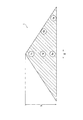
- FIG. 1 is a cross-sectional view of a pile 1.
- FIG. 2 is a diagram showing a flow of the spontaneous ignition prediction method S1.
- FIG. 3 is a graph showing the relationship between the flow velocity and the pressure loss (in the case of coal B).
- FIG. 4 is a graph showing measured values of oxygen consumption rate (in the case of coal A).
- FIG. 5 is a graph showing measured values of oxygen consumption rates (in the case of coal B).
- FIG. 6 is a graph showing the relationship between relative pressure and equilibrium moisture (in the case of coal A).
- FIG. 7 is a graph showing the relationship between relative pressure and equilibrium moisture (in the case of coal B).
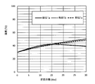
- FIG. 8 is a graph showing the relationship between the number of coal storage days and the temperature (in the case of coal A).
- FIG. 9 is a graph showing the relationship between the number of coal storage days and the temperature (in the case of coal B).
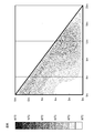
- FIG. 10 is a diagram showing an analysis result of the oxygen concentration distribution on the 24th day (in the case of coal A).
- FIG. 11 is a diagram showing an analysis result of the oxygen concentration distribution on the 24th day (in the case of coal B).
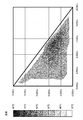
- FIG. 12 is a diagram showing an analysis result of the temperature distribution on the 24th day (in the case of coal A).
- FIG. 13 is a diagram illustrating an analysis result of the temperature distribution on the 24th day (in the case of coal B).
- FIG. 14 is a diagram showing actual measurement results of the temperature distribution on the 24th day (in the case of coal B).
- the pile 1 is a pile of coal (a pile of coal, a pile of coal, a packed bed of coal).
- the pile 1 is a coal storage pile formed when coal is stored (coal storage).
- the pile 1 is formed (formed) by a stacker facility.
- the stacker facility is a facility for stacking coal on a coal storage site, and is a facility for dropping coal onto the coal storage site and stacking the coal.
- the pile 1 is provided in a coal storage facility such as an office that uses coal.
- This pile 1 generates heat due to the oxidation reaction of coal. Details of the heat generation are as follows (a) to (d).
- Air atmosphere
- C The temperature of coal rises by this oxidation reaction.
- the pile 1 When the pile 1 is heated to some extent (before the coal is ignited), the pile 1 is paid out.
- the payout of the pile 1 is, for example, to break the pile 1 in order to use the coal, and for example, to break the pile 1 without using the coal (the pile 1 is then rebuilt).
- the temperature at which the pile 1 is discharged is, for example, about 60 ° C.
- the payout days of the pile 1 (the number of days from when the pile 1 is established until the payout is performed) is, for example, about 2 weeks to about 1 month.
- This pile 1 has a mountain shape.
- the shape of the pile 1 is, for example, a cone (such as a cone or a pyramid), a trapezoid (such as a truncated cone or a truncated pyramid), and a mountain range, for example.
- the cross-sectional shape of the pile 1 is a mountain shape.
- the cross-sectional shape of the pile 1 is, for example, a triangle, and is, for example, a trapezoid.
- the “cross section” is a plane perpendicular to the horizontal plane, and is a plane passing through the highest portion of the pile 1. Below, the case where the shape of the pile 1 is a cone shape (the cross-sectional shape of the pile 1 is a triangle) is demonstrated.
- a direction parallel to the bottom of the cross section of the pile 1 is defined as a left-right direction X.
- the height h of the pile 1 is about 10 m to 15 m.
- the part 1 a is a skirt part of the pile 1.
- part 1a is the lower end part of the cross section of the pile 1, and the left-right direction X outer side edge part.
- the part 1b is the middle abdomen of the pile 1.
- part 1b is an up-down direction center part of the cross section of the pile 1, and the left-right direction X outer side edge part.
- Site 1 c is the top of pile 1.
- the part 1 c is the upper end of the cross section of the pile 1.
- the part 1d is the central part of the cross section of the pile 1.
- the part 1d is the central part in the vertical direction and the central part in the horizontal direction X of the cross section of the pile 1.
- the site 1 e is the bottom of the cross section of the pile 1.
- part 1e is the lower end part of the cross section of the pile 1, and the left-right direction X center part.
- This pile 1 is made of coal.
- coal There are various brands of coal. Depending on the brand of coal, the ratio of the substances that make up the coal varies. Coal is composed of carbon, oxygen, hydrogen, nitrogen, sulfur, moisture, and inorganic content (ash). Coal with a higher ratio of oxygen to carbon atoms in the coal (O / C ratio) is more likely to generate heat. Examples of coal include coal A and coal B shown in Table 1. Coal B has a higher O / C ratio than coal A (highly exothermic). Coal B has a higher moisture content than coal A. In addition, the moisture [%] in Table 1 is the ratio of the mass of moisture to the mass of coal.
- the spontaneous ignition prediction method S1 (see FIG. 2) is a method for predicting the heat generation of the coal constituting the pile 1.
- the pile 1 will be described with reference to FIG. 1, and the spontaneous ignition prediction method S1 will be described with reference to FIG.
- the spontaneous ignition prediction method S1 is a method for predicting spontaneous ignition of coal by predicting a temporal change (heat generation characteristic) of the temperature distribution in the pile 1 by analysis (numerical analysis, calculation, simulation).
- the spontaneous ignition prediction method S1 is a method for predicting when and how a part of the pile 1 generates heat.
- the spontaneous ignition prediction method S1 performs the above prediction based on the physical property value of coal (refer to a physical property value determination step Sp described later).
- the spontaneous ignition prediction method S1 In the spontaneous ignition prediction method S1, it is not necessary to directly measure the pile 1 information (temperature, gas components, etc.). Therefore, the spontaneous ignition prediction method S1 does not need to be performed after the pile 1 is created.
- the spontaneous ignition prediction method S1 is performed before the pile 1 is set.
- the spontaneous ignition prediction method S1 may be performed while the pile 1 is being created or after the pile 1 is being created.
- the temperature in the pile 1 (temperature rise) depends on the heat generated by the oxidation reaction of coal, the heat conduction in the pile 1, and the heat taken away from the coal by desorption (evaporation) of water. Therefore, in the spontaneous ignition prediction method S1, a heat generation rate determination S10, an effective thermal conductivity determination S40, and an evaporation heat amount determination S50 are performed.
- heat generation rate S10 the heat generation rate of coal due to oxidation reaction is determined (estimated).
- the heat generation rate of coal due to the oxidation reaction is derived from the reaction rate of the oxidation reaction. This reaction rate depends on the oxygen concentration in the pile 1. Therefore, in the heat generation rate determination S10, an oxygen concentration determination S20 and a reaction rate determination S30 are performed.
- the oxygen concentration distribution in the pile 1 is determined.
- the oxygen concentration distribution in the pile 1 is derived from the pressure loss at each part in the pile 1 (details will be described later).
- the pressure loss depends on the particle size of the coal.
- the pressure loss also depends on the flow rate of air through the coal particles. Therefore, in the oxygen concentration determination S20, a particle size distribution determination step S21, a ventilation resistance coefficient determination step S22, a pressure loss determination step S23, and an oxygen concentration determination step S24 are performed.
- the particle size distribution determining step S21 is a step of determining the particle size distribution of the coal in the pile 1.
- step is omitted, and “determination of particle size distribution” is described (the same applies to other steps).
- the particle size distribution determining step S21 the filling state of the coal particles in the pile 1 is grasped.
- the particle size of coal varies depending on the site in the pile 1 (has a wide particle size distribution). For example, when the pile 1 has a conical shape, coal having a large particle diameter tends to gather at the skirt (part 1a).
- the necessity of determining the particle size distribution is as follows. There is an Ergun equation as an empirical equation for predicting pressure loss in the packed bed. The Ergun formula can be applied when the particle diameter is uniform.
- the method for determining the particle size distribution in the particle size distribution determining step S21 includes an experiment (experimental method) and an analysis (analysis method).
- the particle size distribution of the pile 1 is determined by actually measuring the particle size distribution of the minipile.
- the mini-pile is a test pile that simulates the pile 1 (actual).
- the size of the minipile is smaller than that of the pile 1 and can be manufactured, for example, in a laboratory.
- the height of the mini pile is, for example, 1/10 of the height h of the pile 1 (for example, when the height h of the pile 1 is 15 m, the height of the mini pile is 1.5 m).
- the particle size distribution of the pile 1 is estimated by actually measuring the particle size distribution of the mini pile.
- the particle size distribution is measured, for example, as follows. A coal particle group is collected from each part (referred to as parts 1a to 1e) of the mini pile corresponding to the parts 1a to 1e of the pile 1. Then, the average particle diameter is measured for each collected particle group.
- the parts where the particle diameter was collected and measured were the minipile parts 1a to 1e.
- the site where the measurement is performed need not be the sites 1a to 1e.
- the part where the measurement or the like is performed may be only a part of the parts 1a to 1e, for example, or may be a part other than the parts 1a to 1e.
- the number of parts where measurement or the like is performed may be 4 or less, or 6 or more.
- the estimated value may be calculated at (part). The same applies to ( ⁇ ) to ( ⁇ ) when measurement, analysis, etc. are performed in steps other than the particle size distribution determination step S21.
- the particle size distribution in the pile 1 is determined by analysis.
- An analysis for determining the particle size distribution includes, for example, a DEM simulation (DEM: Discrete Element Element Method).
- the particle size distribution determining step S21 includes an experiment and an analysis. Similarly, the following can be said for each step described below.
- what is determined by analysis may be determined by experiment if it can be determined by experiment.
- what is determined by experiment may be determined by analysis if it can be determined by analysis.
- when known information such as information previously examined by others
- neither experiment nor analysis is performed. May be determined.
- the temperature distribution predicted value determined in the temperature distribution predicted value determination step S60 described later is always determined by analysis.
- the ventilation resistance coefficient determination step S22 is a step of determining the ventilation resistance coefficient k.
- the airflow resistance coefficient k is determined from the relationship between the flow velocity of gas (air) passing through the coal particle group having a certain particle diameter (at a certain site) and the pressure loss.
- the ventilation resistance coefficient k is a coefficient (constant) in the relational expression between the flow velocity and the pressure loss.
- the ventilation resistance coefficient k varies depending on the portion in the pile 1.
- the parts where the airflow resistance coefficient k is determined are, for example, the parts 1a to 1e.
- the ventilation resistance coefficient k is determined by experimental measurement.
- the measurement and determination of the ventilation resistance coefficient k are performed, for example, as in the following (S22-a) to (S22-e).
- S22-a A system filled with coal of a certain particle diameter (coal at a certain part, for example, coal at the part 1a of the minipile) is prepared.
- This system includes a tube and a packed bed (a coal particle group, a coal particle group) in the tube.
- the cylinder is preferably a cylinder.
- Dry air is introduced from one end (inlet, for example, lower end) in the axial direction of the cylinder, and dried air is discharged from the other end (outlet, for example, upper end). Thereby, dry air passes through the packed bed.
- the pressure loss of air in the packed bed (pressure loss ⁇ P / L) is obtained from the pressure difference ( ⁇ P) between the inlet and outlet and the length (L) of the packed bed.
- a plurality of pressure losses ⁇ P / L are obtained using the value of the flow velocity (flow velocity u) of the dry air passing through the packed bed as a parameter. From this measurement result, the ventilation resistance coefficient k is obtained.
- the airflow resistance coefficient k is measured for each of a plurality of particle diameters (for example, the minipile portions 1b to 1e).
- FIG. 3 is a graph showing the relationship between the flow velocity u and the pressure loss ⁇ P / L for each of the parts 1a, 1b and 1c of the coal B minipile. As shown in this graph, the following relationship is established between the flow velocity u and the pressure loss ⁇ P / L.
- ⁇ P / L k ⁇ u
- k is a ventilation resistance coefficient [Pa / m 2 / s], which is an inclination of the graph of FIG.
- the pressure loss determination step S23 is a step for determining the pressure loss ⁇ P / L.
- the pressure loss ⁇ P / L is determined for each of a plurality of particle sizes (a plurality of parts, for example, parts 1a to 1e).
- the pressure loss ⁇ P / L is determined based on the ventilation resistance coefficient k determined in the ventilation resistance coefficient determination step S22 and the flow velocity u that changes with time according to the temperature change of the coal.
- the details of the “flow rate u that changes with time” are as follows. For example, when the temperature in the pile 1 rises, the volume of air expands.
- the pressure loss ⁇ P / L is determined using the ventilation resistance coefficient k. Thereby, the change with time of the pressure loss ⁇ P / L according to the change with time of the flow velocity u can be estimated.
- the “flow rate u that changes with time” can be predicted as follows.
- the temperature difference between the temperature of the pile 1 and the temperature of the air causes a difference in the density of the air (higher temperature is lower than low temperature). Due to this density difference, in the initial stage when the pile 1 is formed, air flows into the pile 1 from outside the pile 1. Therefore, from the relationship between this density difference and pressure loss ⁇ P / L (pressure loss ⁇ P / L not considering the flow rate u that changes with time, pressure loss ⁇ P / L based on the particle diameter), the initial stage where the pile 1 was formed It is possible to predict the flow velocity u of air in the pile 1 (initial flow velocity u). Based on this initial flow velocity u, the flow velocity u after the “certain time” has elapsed since the pile 1 was formed is predicted. Then, the flow velocity u is repeatedly predicted while changing the “certain time”. As a result, the “flow rate u changing with time” can be predicted.
- the oxygen concentration determination step S24 is a step of determining the oxygen concentration distribution (air state) in the pile 1.
- the oxygen concentration distribution is predicted (estimated) by analysis.
- the oxygen concentration in the pile 1 is derived from the pressure loss ⁇ P / L in the pile 1.
- the pressure loss ⁇ P / L varies depending on the particle diameter of coal (depending on the portion in the pile 1). Therefore, in the oxygen concentration determination step S24, the particle size distribution determined in the particle size distribution determination step S21 and the pressure loss ⁇ P / L determined in the pressure loss determination step S23 (pressure loss ⁇ P / L at a certain particle size). Based on the above, the oxygen concentration distribution is determined.
- the reaction rate of the oxidation reaction of the coal in the pile 1 is determined.
- the heat generation rate of coal is derived from the reaction rate of the oxidation reaction. Further, the oxidation reaction is deactivated (described later). Therefore, in the determination S30 of the reaction rate or the like, an inactivation characteristic determination step S31, various physical property value determination steps S32, a reaction rate determination step S33, and an exothermic rate determination step S34 are performed.
- the deactivation characteristic determination step S31 is a step of determining the deactivation characteristic of the reaction rate of the oxidation reaction of coal (ascertaining deactivation behavior). Deactivation occurs as follows. By the oxidation reaction, an oxide film is formed on the surface of the coal. As a result, the reaction rate of the oxidation reaction decreases as the oxidation reaction proceeds. This deactivation is a phenomenon similar to coal weathering. Since the oxidation reaction proceeds by the consumption of oxygen by coal, the reaction rate of the oxidation reaction can be organized by the oxygen consumption rate (OCR: Oxygen Consumption Rate). The oxygen consumption rate is measured by experiment.
- OCR Oxygen Consumption Rate
- the oxygen consumption rate is measured and determined, for example, as in the following (S31-a) to (S31-d).
- S31-a Coal (coal sample) and dry air are placed in a container (for example, a plastic container), and the container is sealed.
- S31-b The inside of the container is held at 30 ° C. for 1 hour.
- S31-c Thereafter, the oxygen concentration (gas composition) in the container is measured.
- the oxygen consumption rate (measured value of the oxygen consumption rate) OCR 0 is obtained from the oxygen decrease amount based on the decrease amount of the oxygen concentration, the coal sample weight, and the measurement time by the following equation.
- OCR 0 Oxygen reduction amount [mg] / (coal sample weight [g] ⁇ measurement time [day])
- FIGS. 4 and 5 are graphs showing the relationship between the oxygen consumption rate and the cumulative oxygen amount.
- the cumulative oxygen amount on the horizontal axis of the graph is the cumulative amount of oxygen decrease, and is the amount of oxygen accumulated in coal due to the oxidation reaction.
- FIG. 4 shows the measurement result of coal A
- FIG. 5 shows the measurement result of coal B. The following can be understood from the graphs of FIGS. 4 and 5.
- the oxygen consumption rate differs depending on the brand of coal (for example, between coal A and coal B). The higher the O / C ratio (coal B than coal A), the faster the oxygen consumption rate.
- the various physical property value determination step S32 is a step of determining physical property values (physical property values other than the deactivation characteristics) of coal used in the reaction rate determination step S33 and the heat generation rate determination step S34.
- the physical property values of coal determined in the various physical property value determination step S32 are the activation energy ⁇ E, the reaction order n, the solid density ⁇ s , the heat generation amount H, and the porosity ⁇ in the pile 1. These physical property values are determined by measurement of coal or minipile.
- the reaction rate determination step S33 is a step of determining (estimating by analysis) the reaction rate of the coal oxidation reaction (low-temperature oxidation reaction rate OCR).
- the low-temperature oxidation reaction rate OCR depends on the oxygen concentration C, the temperature T, and the like. These relationships can be expressed by the following equation (Arrhenius equation).
- OCR OCR 0 ⁇ exp [( ⁇ ⁇ E / R) (1 / T ⁇ 1 / T 0 )] ⁇ (C / 21) n
- OCR 0 Actual value of oxygen consumption rate [mg-O 2 / (g ⁇ day)]
- ⁇ E activation energy [kJ / mol]
- R Gas constant [kJ / (mol ⁇ K)]
- T Temperature [K]
- T 0 Initial temperature [K]
- C Oxygen concentration [mol%]
- n Reaction order [ ⁇ ]
- the heat generation rate determination step S34 is a step of determining (estimating by analysis) the heat generation rate (heat generation rate Q) due to the oxidation reaction of coal.
- the heat generation rate Q is determined based on the low temperature oxidation reaction rate OCR determined in the reaction rate determination step S33. More specifically, in the heat generation rate determination step S34, the heat generation rate Q is based on the low temperature oxidation reaction rate OCR determined based on the oxygen concentration C (oxygen concentration distribution) and the actually measured value OCR 0 (deactivation characteristics) of the oxygen consumption rate. Is determined.
- the heat generation rate Q is derived from the following equation.
- the effective thermal conductivity in the pile 1 is determined.
- the reason for determining the effective thermal conductivity is as follows. Heat generated by the oxidation of coal (more specifically, heat obtained by subtracting heat removed by evaporation of water from heat generated by oxidation) is transferred to the surroundings. Since there are voids between the coal particles in the pile 1, this heat transfer behavior depends on the effective thermal conductivity of the pile 1. Therefore, in the determination S40 of the effective thermal conductivity, a coal thermal conductivity determination step S41 and an effective thermal conductivity determination step S42 are performed.
- Coal thermal conductivity determination step S41 is a step of determining the thermal conductivity of coal (coal thermal conductivity k s ).
- the effective thermal conductivity determination step S42 is a step of determining an effective thermal conductivity (effective thermal conductivity k eff [W / (m ⁇ K)]) based on the porosity of the pile 1.
- the effective thermal conductivity k eff can be organized as a volume average of the thermal conductivity of air (fluid) and the thermal conductivity of coal (solid).
- the amount of heat taken from the coal by the evaporation (desorption) of water from the coal is determined.
- the details of evaporation are as follows.
- the amount of moisture adsorbed on coal depends on the relative pressure (water vapor pressure / saturated water vapor pressure) (depends on the relative humidity). For example, when the temperature of coal rises, water evaporates from the coal, and the evaporated water is released outside the pile 1 (outside the system). As water evaporates from the coal, heat is taken away from the coal. This heat is covered by the amount of heat generated by the coal oxidation reaction.
- the amount of moisture adsorbed on the coal depends on the adsorption / desorption characteristics (described later).
- an adsorption / desorption characteristic determination step S51, an atmospheric condition determination step S52, and a heat of evaporation determination step S53 are performed.
- the adsorption / desorption characteristic determination step S51 is a step of determining the adsorption / desorption characteristics of water with respect to coal. In the adsorption / desorption characteristic determination step S51, the relationship between the relative pressure and the moisture adsorption amount is determined. The adsorption / desorption characteristics vary depending on the brand of coal.
- the adsorption / desorption characteristics of water with respect to coal are measured, for example, as in the following (S51-a) to (S51-d).
- S51-a The coal sample is dried under reduced pressure at 107 ° C. for 6 hours.
- S51-b Thereafter, the coal sample is placed in a container capable of performing pressure operation.
- S51-c Water vapor is supplied into the container.
- S51-d The temperature in the container is kept constant, and the relationship between the relative pressure and the moisture adsorption amount is measured.
- the volume V of the water vapor in the container, the gas constant R, and the temperature T in the container are constant. Therefore, the number of moles n of water molecules adsorbed on the coal sample can be determined from the change in the water vapor pressure P in the container. As a result, moisture [%] in the coal sample can be derived.
- FIGS. 6 and 7 show the measurement results of the adsorption / desorption characteristics at 40.degree. 6 and 7 are graphs showing the relationship between relative pressure and equilibrium moisture (moisture in a coal sample when water adsorption / desorption on coal is in an equilibrium state).
- FIG. 6 shows the measurement result of coal A
- FIG. 7 shows the measurement result of coal B.
- Atmospheric condition determination step S52 is a step of determining air conditions (atmospheric conditions) in the vicinity of pile 1 (around pile 1 or in pile 1).
- the atmospheric conditions to be determined are, for example, atmospheric temperature and humidity.
- the evaporation heat amount determination step S53 is a step of determining the heat of evaporation when water evaporates from the coal.
- the heat of evaporation determination step S53 the heat of evaporation is determined based on the adsorption / desorption characteristics determined in the adsorption / desorption characteristic determination step S51 and the atmospheric conditions determined in the atmospheric condition determination step S52.
- the amount of heat of evaporation is determined from the amount of water evaporated from coal [g] and the latent heat of vaporization (2259 [J / g]).
- the temperature distribution predicted value determination step S60 is a step of determining the predicted value of the temperature distribution in the pile 1 over time (temperature distribution predicted value) by analysis.
- a temperature distribution predicted value is determined based on the physical property value of coal determined in physical property value determination step Sp (described later).
- the temperature distribution predicted value is determined based on the heat generation rate Q determined in the heat generation rate determination step S34 (in the heat generation rate determination S10).
- the temperature distribution predicted value determination step S60 is determined based on the effective thermal conductivity k eff determined in the effective thermal conductivity determination step S42 (in the effective thermal conductivity determination S40).
- the temperature distribution predicted value determination step S60 the temperature distribution predicted value is determined based on the heat of evaporation determined in the heat of evaporation determination step S53 (in the determination of heat of evaporation S50). In the temperature distribution predicted value determination step S60, the temperature distribution predicted value is determined in consideration of chemical reaction, fluid, heat transfer, and gas diffusion. In the temperature distribution predicted value determination step S60, conditions other than the conditions (relational expressions and values) used in each step described above may be used for the analysis.
- the “temperature distribution” predicted in the temperature distribution predicted value determination step S60 includes information on the position and temperature of each “plurality of parts” in the pile 1.
- the “plurality of parts” is set, for example, at intervals of several centimeters (for example, 1 cm intervals) on the top and bottom and the left and right in the cross section of the pile 1.
- the “plurality of sites” are the sites 1a to 1e (for example, 5 sites) of the pile 1 corresponding to the sites 1a to 1e where coal is extracted from the mini pile in the particle size distribution determination step S21 by experiment.
- the “plurality of parts” is between the parts 1a to 1e or around the parts 1a to 1e.
- the “predicted value of change with time” is a predicted value at each of a plurality of times.
- the interval between the “plural times” is, for example, several hours, for example, one day, or, for example, a plurality of days.
- the physical property value determining step Sp is a step of determining the physical property value of coal constituting the pile 1.
- the physical property value determining step Sp includes a particle size distribution determining step S21, a ventilation resistance coefficient determining step S22, a deactivation characteristic determining step S31, various physical property value determining steps S32, a coal thermal conductivity determining step S41, and an adsorption / desorption characteristic determining step. S51 is included.
- FIG. 8 Result of coal A
- FIG. 9 Result of coal B
- the temperature of Coal B which is a high O / C coal (Coal B having a higher O / C ratio than Coal A), is higher than that of Coal A.
- the temperature rise is remarkable in the part 1a (the part where the coal having a large particle diameter is larger than the other part) compared to the other part.
- the temperature increase is remarkable in the part 1a during the days of coal storage: Day 0 to Day 6.
- the number of days of coal storage In the 13th to 30th days, the temperature of the part 1b is higher than that of other parts.
- the temperature is approximately the same in the region 1b and the region 1c.
- the spontaneous ignition prediction method S1 was used to predict (analyze) the oxygen concentration distribution and temperature distribution in the pile 1 on the 24th day of coal storage.
- the analysis results are shown in FIGS.
- the triangle shown in FIGS. 10 to 13 is the right half portion of the cross section of the symmetrical pile 1 (the same applies to FIG. 14 described later).
- the analysis results of the oxygen concentration distribution are shown in FIG. 10 (result of coal A) and FIG. 11 (result of coal B). From this result, it can be seen that the oxygen concentration at the base of the pile 1 (in the vicinity of the portion 1a in FIG. 1) is higher than the other portions.
- the analysis result of temperature distribution is shown in FIG. 12 (result of coal A) and FIG.
- the temperature (temperature level) of the high temperature spot (the highest temperature in the pile 1) is about 70 ° C.
- the position of the high temperature spot is in the vicinity of the middle abdomen (part 1b in FIG. 1). More specifically, the position of the high temperature spot is about 5 m above the lower end (0 m) of the pile 1 and about 11 m outward from the center (0 m) in the left-right direction X of the pile 1 (right side in FIG. 13). Position.
- the analysis result and the measurement result were compared for the temperature distribution in the pile 1.
- the number of temperature measurement points is 15, and the interval between the measurement points is 2.5 m in the vertical direction and about 2 to 3 m in the horizontal direction X (see FIG. 1) (above the lower part of the pile 1). Increased spacing).
- the actual measurement result of the temperature distribution in the pile is shown in FIG. Comparing the analysis result shown in FIG. 13 with the actual measurement result shown in FIG. 14, it can be seen that the position of the high temperature spot (details are described above) and the temperature level (about 70 ° C.) are in good agreement.
- the spontaneous ignition prediction method S1 is a method for predicting spontaneous ignition of coal constituting the pile 1 (coal bed in the coal storage facility).
- the spontaneous ignition prediction method S1 includes a physical property value determining step Sp for determining a physical property value of coal, and a temperature distribution predicted value determining step S60.
- a temperature distribution predicted value determination step S60 based on the physical property value determined in the physical property value determination step Sp, a temperature distribution predicted value that is a predicted value of the temperature distribution in the pile 1 with time is determined by analysis. It is a step to do.
- the temperature distribution predicted value determined in the temperature distribution predicted value determination step S60 is determined based on the physical property value of coal. In order to determine the physical property value of coal, it is only necessary to have coal, and it is not necessary to build a real pile 1. Therefore, the cost and labor required to build the pile 1 can be reduced.
- the temperature distribution predicted value is a predicted value of the temperature distribution in the pile 1 with time. Therefore, if the predicted temperature distribution value is determined, it is possible to predict when the coal reaches the spontaneous ignition temperature (for example, the number of coal storage days) and the position (part) at which the coal reaches the spontaneous ignition temperature. As a result, it is possible to determine the upper limit of the number of coal storage days (upper limit of payout days) in which coal can be stored without spontaneous combustion.
- the spontaneous ignition prediction method S1 includes a heat generation rate determination step S34 for determining the heat generation rate Q due to the oxidation reaction of coal.
- the temperature distribution predicted value determination step S60 the temperature distribution predicted value is determined based on the heat generation rate Q determined in the heat generation rate determination step S34.
- the temperature change in the pile 1 greatly depends on the heat generated by the oxidation reaction of coal. Therefore, in the above [Configuration 2], the predicted temperature distribution value is determined based on the heat generation rate Q due to the oxidation reaction. Therefore, the temperature distribution predicted value can be predicted more reliably.
- the spontaneous ignition prediction method S1 includes an oxygen concentration determination step S24 that determines the oxygen concentration distribution in the pile 1.
- the heat generation rate Q is determined based on the oxygen concentration distribution determined in the oxygen concentration determination step S24.
- the heat generation rate Q due to the oxidation reaction of coal greatly depends on the oxygen concentration distribution in the pile 1. Therefore, in the above [Configuration 3], the heat generation rate is determined based on the oxygen concentration distribution. Therefore, the heat generation rate Q can be reliably predicted, and as a result, the temperature distribution predicted value can be predicted more reliably.
- the spontaneous ignition prediction method S1 includes a particle size distribution determination step S21 and a pressure loss determination step S23.
- the particle size distribution determining step S21 is a step of determining the particle size distribution of coal in the pile 1.
- the pressure loss determination step S23 determines the pressure loss ⁇ P / L of the gas passing through the coal particle group (of a certain part) with a certain particle diameter for each of a plurality of particle diameters (for example, for the parts 1a to 1e). It is a step to decide.
- the oxygen concentration determination step S24 is based on the particle size distribution determined in the particle size distribution determination step S21 and the pressure loss ⁇ P / L determined in the pressure loss determination step S23. It is a step to determine.
- the oxygen concentration distribution in the pile 1 depends on the pressure loss ⁇ P / L in the pile 1.
- the pressure loss ⁇ P / L depends on the particle size of the coal. Therefore, in the above [Configuration 4-1] to [Configuration 4-3], the oxygen concentration distribution is determined based on the pressure loss ⁇ P / L of each of the plurality of particle sizes and the particle size distribution. Therefore, the oxygen concentration distribution can be reliably predicted, and as a result, the heat generation rate Q and the temperature distribution predicted value can be predicted more reliably.
- Spontaneous ignition prediction method S1 is a method of determining a ventilation resistance coefficient k from a relationship between a flow velocity u of gas passing through a coal particle group having a certain particle diameter (at a certain site) and a pressure loss ⁇ P / L.
- a coefficient determination step S22 is included.
- the pressure loss determination step S23 the pressure loss ⁇ P / L is based on the ventilation resistance coefficient k determined in the ventilation resistance coefficient determination step S22 and the flow velocity u that changes with the temperature of coal. To decide.
- the pressure loss ⁇ P / L of a gas passing through a coal particle group having a certain particle size depends on the flow velocity u of the gas. This flow rate changes with time. Therefore, in the above [Configuration 5-1], the ventilation resistance coefficient k is determined from the relationship between the flow velocity u and the pressure loss ⁇ P / L. In the [Configuration 5-2], the pressure loss ⁇ P / L is determined based on the flow velocity u and the ventilation resistance coefficient k that change with time. Therefore, the pressure loss ⁇ P / L can be reliably predicted, and as a result, the oxygen concentration distribution, the heat generation rate Q, and the temperature distribution predicted value can be predicted more reliably.
- the spontaneous ignition prediction method S1 includes a deactivation characteristic determination step S31 that determines the deactivation characteristic of the reaction rate of the oxidation reaction of coal. [Configuration 6] In the heat generation rate determination step S34, the heat generation rate Q is determined based on the deactivation characteristics determined in the deactivation characteristic determination step S31.
- the heat generation rate Q is determined based on the deactivation characteristics. Therefore, the heat generation rate can be predicted with certainty, and as a result, the temperature distribution predicted value can be predicted with more certainty.
- the spontaneous ignition prediction method S1 includes an effective thermal conductivity determination step S42 that determines an effective thermal conductivity k eff based on the porosity in the pile 1.
- the temperature distribution predicted value determination step S60 determines a temperature distribution predicted value based on the effective thermal conductivity k eff determined in the effective thermal conductivity determination step S42.
- the heat conduction in the pile 1 depends on the effective heat conductivity k eff based on the porosity in the pile 1. Therefore, in the above [Configuration 7], the predicted temperature distribution value is determined based on the effective thermal conductivity k eff . Therefore, the temperature distribution predicted value can be predicted more reliably.
- the spontaneous ignition prediction method S1 includes an adsorption / desorption characteristic determination step S51 for determining water adsorption / desorption characteristics for coal, an atmospheric condition determination step S52 for determining atmospheric conditions in the vicinity of the pile 1, and an evaporation heat amount determination step S53. .
- adsorption / desorption characteristic determination step S51 for determining water adsorption / desorption characteristics for coal
- an atmospheric condition determination step S52 for determining atmospheric conditions in the vicinity of the pile 1
- an evaporation heat amount determination step S53 In the evaporation heat quantity determination step S53, water evaporates from the coal based on the adsorption / desorption characteristics determined in the adsorption / desorption characteristic determination step S51 and the atmospheric conditions determined in the atmospheric condition determination step S52. This is a step of determining the amount of heat of evaporation.
- a temperature distribution predicted value determination step S60 determines a temperature distribution predicted value based on the heat of evaporation determined in the heat of vapor determination step
- the amount of heat (evaporation heat) taken from the coal when the water in the coal evaporates depends on the adsorption / desorption characteristics and the atmospheric conditions. Therefore, in [Configuration 8-1] and [Configuration 8-2], the predicted temperature distribution value is determined based on the adsorption / desorption characteristics and atmospheric conditions. Therefore, the temperature distribution predicted value can be predicted more reliably.
- the above embodiment can be variously modified.
- the order of the steps shown in FIG. 2 may be changed to an order other than the order shown in FIG. 2 (if it is within the range in which the temperature distribution predicted value can be determined in the temperature distribution predicted value determining step S60) May be).
- the heat generation rate determination S10, the effective thermal conductivity determination S40, and the evaporation heat amount determination S50 need not be performed in the order shown in FIG.
- the various physical property value determination step S32 may be performed at the beginning of the spontaneous ignition prediction method S1 (for example, before the particle size distribution determination step S21).
Landscapes
- Health & Medical Sciences (AREA)
- Life Sciences & Earth Sciences (AREA)
- Chemical & Material Sciences (AREA)
- General Health & Medical Sciences (AREA)
- Physics & Mathematics (AREA)
- Analytical Chemistry (AREA)
- Biochemistry (AREA)
- General Physics & Mathematics (AREA)
- Immunology (AREA)
- Pathology (AREA)
- Food Science & Technology (AREA)
- Medicinal Chemistry (AREA)
- Engineering & Computer Science (AREA)
- Investigating Or Analyzing Materials Using Thermal Means (AREA)
- Solid Fuels And Fuel-Associated Substances (AREA)
Abstract
Description
部位1aは、パイル1の裾野部である。部位1aは、パイル1の断面の下端部、かつ、左右方向X外側端部である。
部位1bは、パイル1の中腹部である。部位1bは、パイル1の断面の上下方向中央部、かつ、左右方向X外側端部である。
部位1cは、パイル1の頂上部である。部位1cは、パイル1の断面の上端部である。
部位1dは、パイル1の断面の中央部である。部位1dは、パイル1の断面の上下方向中央部、かつ、左右方向X中央部である。
部位1eは、パイル1の断面の底部である。部位1eは、パイル1の断面の下端部、かつ、左右方向X中央部である。

部位1a:29.8 部位1b:6.2 部位1c:6.3
部位1d:4.2 部位1e:2.2
この結果から、粒子径の大きい石炭が、パイル1の裾野部(部位1a)に集まることがわかる。
ΔP/L=k・u
ここでkは通気抵抗係数[Pa/m2/s]であり、図3のグラフの傾きである。
OCR0=酸素減少量[mg]/(石炭試料重量[g]・測定時間[day])
OCR=OCR0・exp[(-△E/R)(1/T-1/T0)]・(C/21)n
OCR0:酸素消費速度の実測値[mg-O2/(g・day)]
ΔE:活性化エネルギー[kJ/mol]
R:気体定数[kJ/(mol・K)]
T:温度[K]
T0:初期温度[K]
C:酸素濃度[mol%]
n:反応次数[-]
Q=ΔH・(1-ε)・ρs・OCR
Q:発熱速度(酸化反応による石炭の発熱速度)[kcal/(m3・day)]
ΔH:発熱量(酸化反応による石炭の発熱量)[kcal/mg-O2]
ε:パイル1内の空隙率[-]
ρs:石炭の固体密度[kg/m3]
keff=εkf+(1-ε)ks
ε:パイル1内の空隙率[-]
kf:空気の熱伝導率[W/(m・K)]
ks:石炭の熱伝導率[W/(m・K)]
自然発火予測方法S1を用いて、パイル1内の温度の経時変化を予測(解析)した。石炭Aおよび石炭Bそれぞれについて解析を行った。パイル1をたてた時から30日間について解析を行った。部位1a(裾野部)、部位1b(中腹部)、及び部位1c(頂上部)について解析を行った。この解析では、高さh=15[m]の円錐状のパイル1を対象とした。解析結果を図8(石炭Aの結果)及び図9(石炭Bの結果)に示す。図8及び図9は、貯炭日数と温度との関係を示すグラフである。この結果から、次のことがわかる。石炭Aと石炭Bとを比較すると、高O/C炭である石炭B(石炭AよりもO/C比が高い石炭B)の方が、石炭Aよりも温度が上がりやすい。特に石炭Bでは、部位1a(他の部位に比べ大粒子径の石炭が多い部位)において、他の部位に比べて温度上昇が顕著である。具体的には、石炭Bにおいて、貯炭日数:0日目~6日目では、部位1aで温度上昇が顕著である。石炭Bにおいて、貯炭日数:13日目~30日目では、部位1bの温度が他の部位に比べて高い。石炭Bにおいて、貯炭日数:30日目では、部位1bと部位1cとでほぼ同じ温度である。
自然発火予測方法S1を用いて、貯炭日数:24日目の、パイル1内の酸素濃度分布および温度分布を予測(解析)した。解析結果を図10~図13に示す。図10~図13に示す三角形は、左右対称のパイル1の断面の右半分の部分である(後述する図14についても同様)。酸素濃度分布の解析結果を、図10(石炭Aの結果)及び図11(石炭Bの結果)に示す。この結果から、パイル1の裾野部(図1の部位1a付近)の酸素濃度が他の部分に比べて高いことがわかる。温度分布の解析結果を、図12(石炭Aの結果)及び図13(石炭Bの結果)に示す。図13から次のことがわかる。高温スポット(パイル1の中で最も温度が高くなる部位)の温度(温度レベル)は、約70℃である。高温スポットの位置は、中腹部(図1の部位1b)の近傍である。さらに詳しくは、高温スポットの位置は、パイル1の下端(0m)から上に約5mの位置、かつ、パイル1の左右方向Xの中央(0m)から外側(図13における右側)に約11mの位置である。
上記の解析の信頼性を検証するために、パイル1内の温度分布について、解析結果と実測結果とを比較した。具体的には、図13の解析結果に対応するパイル1(実物)について、温度分布を実測した。実測に用いたパイル1は、石炭Bにより構成され、高さh=15[m]であり、円錐状のものであり、貯炭日数は24日目である。なお、温度の測定箇所の数は15であり、測定箇所の間隔は、上下方向は2.5m、左右方向X(図1参照)は約2~3mである(パイル1の下部よりも上部で間隔を大きくした)。パイル内の温度分布の実測結果を図14に示す。図13に示す解析結果と、図14に示す実測結果とを比較すると、高温スポットの位置(詳細は上述)、及び、温度レベル(約70℃)が良好に一致していることがわかる。
次に、図2に示す自然発火予測方法S1による効果を説明する。自然発火予測方法S1は、パイル1(石炭貯蔵施設内の石炭層)を構成する石炭の自然発火を予測する方法である。自然発火予測方法S1は、石炭の物性値を決定する物性値決定ステップSpと、温度分布予測値決定ステップS60と、を有する。
[構成1]温度分布予測値決定ステップS60は、物性値決定ステップSpで決定された物性値に基づいて、パイル1内の温度分布の経時変化の予測値である温度分布予測値を解析により決定するステップである。
自然発火予測方法S1は、石炭の酸化反応による発熱速度Qを決定する発熱速度決定ステップS34を有する。
[構成2]温度分布予測値決定ステップS60では、発熱速度決定ステップS34で決定された発熱速度Qに基づいて温度分布予測値が決定される。
自然発火予測方法S1は、パイル1内の酸素濃度分布を決定する酸素濃度決定ステップS24を有する。
[構成3]発熱速度決定ステップS34では、酸素濃度決定ステップS24で決定された酸素濃度分布に基づいて発熱速度Qが決定される。
自然発火予測方法S1は、粒子径分布決定ステップS21と、圧力損失決定ステップS23と、を有する。
[構成4-1]粒子径分布決定ステップS21は、パイル1内の石炭の粒子径分布を決定するステップである。
[構成4-2]圧力損失決定ステップS23は、ある粒子径の(ある部位の)石炭粒子群を通る気体の圧力損失ΔP/Lを、複数の粒子径それぞれについて(例えば部位1a~1eについて)決定するステップである。
[構成4-3]酸素濃度決定ステップS24は、粒子径分布決定ステップS21で決定された粒子径分布、及び、圧力損失決定ステップS23で決定された圧力損失ΔP/L、に基づいて酸素濃度分布を決定するステップである。
[構成5-1]自然発火予測方法S1は、ある粒子径の(ある部位の)石炭粒子群を通る気体の流速uと圧力損失ΔP/Lとの関係から通気抵抗係数kを決定する通気抵抗係数決定ステップS22を有する。
[構成5-2]圧力損失決定ステップS23は、通気抵抗係数決定ステップS22で決定された通気抵抗係数k、及び、石炭の温度変化に伴い経時変化する流速u、に基づいて圧力損失ΔP/Lを決定する。
自然発火予測方法S1は、石炭の酸化反応の反応速度の失活特性を決定する失活特性決定ステップS31を有する。
[構成6]発熱速度決定ステップS34は、失活特性決定ステップS31で決定された失活特性に基づいて発熱速度Qを決定する。
自然発火予測方法S1は、パイル1内の空隙率に基づく有効熱伝導率keffを決定する有効熱伝導率決定ステップS42を有する。
[構成7]温度分布予測値決定ステップS60は、有効熱伝導率決定ステップS42で決定された有効熱伝導率keffに基づいて温度分布予測値を決定する。
自然発火予測方法S1は、石炭に対する水の吸脱着特性を決定する吸脱着特性決定ステップS51と、パイル1付近の大気条件を決定する大気条件決定ステップS52と、蒸発熱量決定ステップS53と、を有する。
[構成8-1]蒸発熱量決定ステップS53は、吸脱着特性決定ステップS51で決定された吸脱着特性、及び、大気条件決定ステップS52で決定された大気条件、に基づいて石炭から水が蒸発する際の蒸発熱量を決定するステップである。
[構成8-2]温度分布予測値決定ステップS60は、蒸発熱量決定ステップS53で決定された蒸発熱量に基づいて温度分布予測値を決定する。
上記実施形態は様々に変形できる。例えば、図2に示す各ステップの順序を、図2に示す順序以外の順序に変更してもよい(温度分布予測値決定ステップS60で温度分布予測値を決定できる範囲内であれば、変更してもよい)。例えば、発熱速度の決定S10と、有効熱伝導率の決定S40と、蒸発熱量の決定S50とは、図2に示す順に行う必要はない。また、例えば、各種物性値決定ステップS32は、自然発火予測方法S1の最初(例えば粒子径分布決定ステップS21の前)に行われてもよい。
なお、本出願は、2014年1月15日付けで出願された日本特許出願(特願2014-005154)に基づいており、その全体が引用により援用される。
S1 自然発火予測方法
S10 発熱速度の決定
S20 酸素濃度の決定
S21 粒子径分布決定ステップ
S22 通気抵抗係数決定ステップ
S23 圧力損失決定ステップ
S24 酸素濃度決定ステップ
S30 反応速度等の決定
S31 失活特性決定ステップ
S32 各種物性値決定ステップ
S33 反応速度決定ステップ
S34 発熱速度決定ステップ
S40 有効熱伝導率の決定
S41 石炭熱伝導率決定ステップ
S42 有効熱伝導率決定ステップ
S50 蒸発熱量の決定
S51 吸脱着特性決定ステップ
S52 大気条件決定ステップ
S53 蒸発熱量決定ステップ
S60 温度分布予測値決定ステップ
Sp 物性値決定ステップ
Claims (8)
- 石炭貯蔵施設内の石炭層を構成する石炭の自然発火予測方法であって、
前記石炭の物性値を決定する物性値決定ステップと、
前記物性値決定ステップで決定された前記物性値に基づいて、前記石炭層内の温度分布の経時変化の予測値である温度分布予測値を解析により決定する温度分布予測値決定ステップと、
を有する石炭の自然発火予測方法。 - 前記石炭の酸化反応による発熱速度を決定する発熱速度決定ステップを有し、
前記温度分布予測値決定ステップは、前記発熱速度決定ステップで決定された前記発熱速度に基づいて前記温度分布予測値を決定する、
請求項1に記載の石炭の自然発火予測方法。 - 前記石炭層内の酸素濃度分布を決定する酸素濃度決定ステップを有し、
前記発熱速度決定ステップは、前記酸素濃度決定ステップで決定された前記酸素濃度分布に基づいて前記発熱速度を決定する、
請求項2に記載の石炭の自然発火予測方法。 - 前記石炭層内の前記石炭の粒子径分布を決定する粒子径分布決定ステップと、
ある前記粒子径の石炭粒子群を通る気体の圧力損失を、複数の前記粒子径それぞれについて決定する圧力損失決定ステップと、
を有し、
前記酸素濃度決定ステップは、前記粒子径分布決定ステップで決定された前記粒子径分布、及び、前記圧力損失決定ステップで決定された前記圧力損失、に基づいて前記酸素濃度分布を決定する、
請求項3に記載の石炭の自然発火予測方法。 - ある前記粒子径の石炭粒子群を通る気体の流速と圧力損失との関係から通気抵抗係数を決定する通気抵抗係数決定ステップを有し、
前記圧力損失決定ステップは、前記通気抵抗係数決定ステップで決定された前記通気抵抗係数、及び、前記石炭の温度変化に伴い経時変化する前記流速、に基づいて前記圧力損失を決定する、
請求項4に記載の石炭の自然発火予測方法。 - 前記石炭の酸化反応の反応速度の失活特性を決定する失活特性決定ステップを有し、
前記発熱速度決定ステップは、前記失活特性決定ステップで決定された前記失活特性に基づいて前記発熱速度を決定する、
請求項2~5のいずれかに記載の石炭の自然発火予測方法。 - 前記石炭層内の空隙率に基づく有効熱伝導率を決定する有効熱伝導率決定ステップを有し、
前記温度分布予測値決定ステップは、前記有効熱伝導率決定ステップで決定された前記有効熱伝導率に基づいて前記温度分布予測値を決定する、
請求項1に記載の石炭の自然発火予測方法。 - 前記石炭に対する水の吸脱着特性を決定する吸脱着特性決定ステップと、
前記石炭層付近の大気条件を決定する大気条件決定ステップと、
前記吸脱着特性決定ステップで決定された前記吸脱着特性、及び、前記大気条件決定ステップで決定された前記大気条件、に基づいて前記石炭から水が蒸発する際の蒸発熱量を決定する蒸発熱量決定ステップと、
を有し、
前記温度分布予測値決定ステップは、前記蒸発熱量決定ステップで決定された前記蒸発熱量に基づいて前記温度分布予測値を決定する、
請求項1に記載の石炭の自然発火予測方法。
Priority Applications (2)
| Application Number | Priority Date | Filing Date | Title |
|---|---|---|---|
| CN201580004232.7A CN105899943A (zh) | 2014-01-15 | 2015-01-15 | 煤的自燃预测方法 |
| KR1020167018685A KR101907762B1 (ko) | 2014-01-15 | 2015-01-15 | 석탄의 자연 발화 예측 방법 |
Applications Claiming Priority (2)
| Application Number | Priority Date | Filing Date | Title |
|---|---|---|---|
| JP2014005154A JP6270494B2 (ja) | 2014-01-15 | 2014-01-15 | 石炭の自然発火予測方法 |
| JP2014-005154 | 2014-01-15 |
Publications (1)
| Publication Number | Publication Date |
|---|---|
| WO2015108121A1 true WO2015108121A1 (ja) | 2015-07-23 |
Family
ID=53543006
Family Applications (1)
| Application Number | Title | Priority Date | Filing Date |
|---|---|---|---|
| PCT/JP2015/050983 Ceased WO2015108121A1 (ja) | 2014-01-15 | 2015-01-15 | 石炭の自然発火予測方法 |
Country Status (4)
| Country | Link |
|---|---|
| JP (1) | JP6270494B2 (ja) |
| KR (1) | KR101907762B1 (ja) |
| CN (1) | CN105899943A (ja) |
| WO (1) | WO2015108121A1 (ja) |
Cited By (7)
| Publication number | Priority date | Publication date | Assignee | Title |
|---|---|---|---|---|
| JP2015132575A (ja) * | 2014-01-15 | 2015-07-23 | 株式会社神戸製鋼所 | 石炭の自然発火予測方法 |
| CN105510383A (zh) * | 2016-01-10 | 2016-04-20 | 西安科技大学 | 煤最短自然发火期与自然发火特性参数测试装置及方法 |
| CN114266160A (zh) * | 2021-12-23 | 2022-04-01 | 华中科技大学 | 一种圆形煤堆内部温度模拟方法和系统 |
| CN116819031A (zh) * | 2023-05-25 | 2023-09-29 | 安徽理工大学 | 一种基于耗氧速率积分的煤自燃倾向性测定方法 |
| JP7516318B2 (ja) | 2021-07-06 | 2024-07-16 | 株式会社神戸製鋼所 | 温度リスク判定方法及び温度リスク判定システム |
| CN119757460A (zh) * | 2024-12-24 | 2025-04-04 | 山东科技大学 | 采空区遗煤在低温氮气环境中自燃规律的模拟方法 |
| CN120375954A (zh) * | 2025-06-25 | 2025-07-25 | 西安科技大学 | 一种基于数值和图像融合的煤自燃温度预测方法 |
Families Citing this family (16)
| Publication number | Priority date | Publication date | Assignee | Title |
|---|---|---|---|---|
| JP6664194B2 (ja) * | 2015-11-12 | 2020-03-13 | Ihi運搬機械株式会社 | 石炭昇温予測管理システム |
| JP6594785B2 (ja) * | 2016-02-02 | 2019-10-23 | 千代田化工建設株式会社 | 貯炭場監視システムおよび貯炭場監視方法 |
| CN105823796A (zh) * | 2016-03-11 | 2016-08-03 | 华电电力科学研究院 | 一种煤场储煤自燃倾向性的测定方法 |
| JP6786940B2 (ja) * | 2016-08-08 | 2020-11-18 | 富士通株式会社 | 発熱検知装置、発熱検知方法および発熱検知プログラム |
| JP6996926B2 (ja) * | 2017-09-29 | 2022-01-17 | 株式会社Ihi | 石炭温度監視システム |
| KR101972673B1 (ko) * | 2017-12-13 | 2019-04-25 | (주) 피플아이 | Hmm을 이용한 저탄장 자연발화 예측 방법 |
| KR101972672B1 (ko) * | 2017-12-13 | 2019-04-25 | (주) 피플아이 | 재질과 온도를 고려한 저탄장 자연발화 방지를 위한 압력용기의 응력 해석방법 |
| WO2019127106A1 (zh) * | 2017-12-27 | 2019-07-04 | 常州坤宇环保科技有限公司 | 一种环保型高分子凝胶阻化剂及其制备方法和应用 |
| KR102103642B1 (ko) * | 2018-08-23 | 2020-04-22 | 한서대학교 산학협력단 | 심층신경망을 이용한 저탄장 자연발화 예측방법 |
| CN109184800B (zh) * | 2018-10-15 | 2020-05-29 | 西安科技大学 | 一种煤自燃预警分级方法及预警方法 |
| CN110412074A (zh) * | 2019-07-31 | 2019-11-05 | 辽宁工程技术大学 | 一种多功能煤氧化特征实验装置及其使用方法 |
| CN110578555B (zh) * | 2019-09-12 | 2021-05-04 | 辽宁工程技术大学 | 一种瓦斯抽采钻孔自燃危险预测方法 |
| JP7166314B2 (ja) * | 2020-08-03 | 2022-11-07 | 栗田工業株式会社 | 管理システム、管理装置、管理方法及びプログラム |
| CN113125675A (zh) * | 2021-04-19 | 2021-07-16 | 北京物资学院 | 边缘计算架构的堆场煤炭自燃预警装置和预警方法 |
| CN114264788B (zh) * | 2021-12-23 | 2023-09-29 | 徐州工程学院 | 一种用于工作面不同区域与煤自燃相关度大小的判定方法 |
| CN119104636A (zh) | 2023-09-20 | 2024-12-10 | 宁波工程学院 | 一种煤自燃动态进程特征测定的相似实验系统与方法 |
Family Cites Families (6)
| Publication number | Priority date | Publication date | Assignee | Title |
|---|---|---|---|---|
| JP2574049B2 (ja) | 1990-01-17 | 1997-01-22 | 武夫 三枝 | 有機・無機複合透明均質体及びその製法 |
| JPH03241233A (ja) | 1990-02-16 | 1991-10-28 | Matsushita Electric Ind Co Ltd | 電気コンロ |
| JPH0884782A (ja) | 1994-09-20 | 1996-04-02 | Babcock Hitachi Kk | 堆積石炭の自然発火防止装置 |
| JP3241233B2 (ja) | 1995-04-14 | 2001-12-25 | 三菱重工業株式会社 | 石炭の自然発火予知方法及び装置 |
| CN103063328B (zh) * | 2012-12-28 | 2015-04-29 | 中国神华能源股份有限公司 | 一种非接触式测量露天煤垛内部温度的方法和设备 |
| JP6270494B2 (ja) * | 2014-01-15 | 2018-01-31 | 株式会社神戸製鋼所 | 石炭の自然発火予測方法 |
-
2014
- 2014-01-15 JP JP2014005154A patent/JP6270494B2/ja active Active
-
2015
- 2015-01-15 KR KR1020167018685A patent/KR101907762B1/ko active Active
- 2015-01-15 CN CN201580004232.7A patent/CN105899943A/zh active Pending
- 2015-01-15 WO PCT/JP2015/050983 patent/WO2015108121A1/ja not_active Ceased
Non-Patent Citations (5)
| Title |
|---|
| HAEYANG PAK ET AL.: "Evaluation of Spontaneous Combustion in Stock Pile of Sub-bituminous Coal", KOBE STEEL ENGINEERING REPORTS, vol. 64, no. 1, April 2014 (2014-04-01), pages 22 - 27, XP055213515 * |
| HIROAKI TOMINAGA ET AL.: "Application of simulation technique.Simulation of spontaneous heat generation in coal pile", IDEMITSU TECHNICAL REPORT, vol. 38, no. 4, 15 August 1995 (1995-08-15), pages 8 - 16 * |
| HIROTOSHI YANAGI ET AL.: "Sekitan Silo no Shizen Hatsunetsu Simulation", PROCEEDINGS OF THE ANNUAL CONFERENCE OF THE JAPAN SOCIETY OF CIVIL ENGINEERS KYOTSU SESSION, vol. 50, 1995, pages 118 - 119 * |
| KYURO SASAKI ET AL.: "Water Vapor Adsorption of Coal and Numerical Simulation Related to Its Effect on Spontaneous Combustion in a Low Temperature Range", JOURNAL OF THE MINING AND MATERIALS PROCESSING INSTITUTE OF JAPAN, vol. 108, no. 6, 1992, pages 479 - 486, XP055213457 * |
| MASAHIRO OTA ET AL.: "Estimation of temperature rising behavior on coals stocked in a silo", KENKYU KIHO, vol. 54, 5 January 1990 (1990-01-05), pages 48 - 65 * |
Cited By (9)
| Publication number | Priority date | Publication date | Assignee | Title |
|---|---|---|---|---|
| JP2015132575A (ja) * | 2014-01-15 | 2015-07-23 | 株式会社神戸製鋼所 | 石炭の自然発火予測方法 |
| CN105510383A (zh) * | 2016-01-10 | 2016-04-20 | 西安科技大学 | 煤最短自然发火期与自然发火特性参数测试装置及方法 |
| CN105510383B (zh) * | 2016-01-10 | 2017-03-15 | 西安科技大学 | 煤最短自然发火期与自然发火特性参数测试装置及方法 |
| JP7516318B2 (ja) | 2021-07-06 | 2024-07-16 | 株式会社神戸製鋼所 | 温度リスク判定方法及び温度リスク判定システム |
| CN114266160A (zh) * | 2021-12-23 | 2022-04-01 | 华中科技大学 | 一种圆形煤堆内部温度模拟方法和系统 |
| CN114266160B (zh) * | 2021-12-23 | 2024-06-04 | 华中科技大学 | 一种圆形煤堆内部温度模拟方法和系统 |
| CN116819031A (zh) * | 2023-05-25 | 2023-09-29 | 安徽理工大学 | 一种基于耗氧速率积分的煤自燃倾向性测定方法 |
| CN119757460A (zh) * | 2024-12-24 | 2025-04-04 | 山东科技大学 | 采空区遗煤在低温氮气环境中自燃规律的模拟方法 |
| CN120375954A (zh) * | 2025-06-25 | 2025-07-25 | 西安科技大学 | 一种基于数值和图像融合的煤自燃温度预测方法 |
Also Published As
| Publication number | Publication date |
|---|---|
| KR101907762B1 (ko) | 2018-10-12 |
| JP6270494B2 (ja) | 2018-01-31 |
| KR20160098359A (ko) | 2016-08-18 |
| CN105899943A (zh) | 2016-08-24 |
| JP2015132575A (ja) | 2015-07-23 |
Similar Documents
| Publication | Publication Date | Title |
|---|---|---|
| JP6270494B2 (ja) | 石炭の自然発火予測方法 | |
| Young et al. | The impact of binary water–CO 2 isotherm models on the optimal performance of sorbent-based direct air capture processes | |
| Dutta et al. | Modeling of CO2 sorption on coal | |
| Mayerhofer et al. | Experimental investigation of pressure drop in packed beds of irregular shaped wood particles | |
| Xu et al. | Spontaneous combustion coal parameters for the Crossing-Point Temperature (CPT) method in a Temperature–Programmed System (TPS) | |
| Zhang et al. | Transient CFD modelling of low-temperature spontaneous heating behaviour in multiple coal stockpiles with wind forced convection | |
| Kokkola et al. | The role of low volatile organics on secondary organic aerosol formation | |
| Wu et al. | Thermal structure of methane hydrate fueled flames | |
| Zhang et al. | Modelling and parametric investigations on spontaneous heating in coal pile | |
| Hynes et al. | Uptake of HNO3 on water‐ice and coadsorption of HNO3 and HCl in the temperature range 210–235 K | |
| Li et al. | Effects of oxygen concentration on the macroscopic characteristic indexes of high-temperature oxidation of coal | |
| Li et al. | Adsorption kinetic and equilibrium study for removal of mercuric chloride by CuCl2-impregnated activated carbon sorbent | |
| Komatsu et al. | Hydrogen and carbon dioxide adsorption with tetra‐n‐butyl ammonium semi‐clathrate hydrates for gas separations | |
| CN103307872B (zh) | 一种窑内烟气温度检测方法及装置 | |
| Zhang et al. | Numerical study on heat transfer and release characteristics of key components in electrically heated tobacco products | |
| Hill et al. | Understanding the consequences of CO2 leakage downstream of the capture plant | |
| CN102879599A (zh) | 一种倾斜状态易燃液体火焰传播速度的测定方法和装置 | |
| Akiba et al. | Interfacial tension between (CO2+ N2) gas and tetrabutylammonium bromide aqueous solution | |
| CN109406372A (zh) | 一种松散介质液氮渗流运移特征测试实验装置及方法 | |
| JP6988651B2 (ja) | 石炭の酸化反応試験装置、及びこれを用いた石炭の酸化反応の含水率依存性の測定方法 | |
| Wang et al. | Methane desorption and adsorption measurements on activated carbon in 281–343 K and pressures to 1.2 MPa | |
| CN209570351U (zh) | 用于测试车辆的蒸发排放碳罐的系统以及执行测试的系统 | |
| Skarbalius et al. | Iterative method for fast estimation of convective drying characteristics of biomass | |
| Pham et al. | Numerical and experimental investigations of internal flow characteristics of n-butane adsorption in a carbon canister | |
| Hardjono et al. | Isobaric vapor-liquid equilibrium of 2-propanone+ 2-butanol system at 101.325 kPa: Experimental and molecular dynamics simulation |
Legal Events
| Date | Code | Title | Description |
|---|---|---|---|
| 121 | Ep: the epo has been informed by wipo that ep was designated in this application |
Ref document number: 15737111 Country of ref document: EP Kind code of ref document: A1 |
|
| ENP | Entry into the national phase |
Ref document number: 20167018685 Country of ref document: KR Kind code of ref document: A |
|
| WWE | Wipo information: entry into national phase |
Ref document number: IDP00201604565 Country of ref document: ID |
|
| NENP | Non-entry into the national phase |
Ref country code: DE |
|
| 122 | Ep: pct application non-entry in european phase |
Ref document number: 15737111 Country of ref document: EP Kind code of ref document: A1 |