WO2015104819A1 - ネットワーク経由映像伝送システム、伝送映像切換方法、および、プログラム - Google Patents
ネットワーク経由映像伝送システム、伝送映像切換方法、および、プログラム Download PDFInfo
- Publication number
- WO2015104819A1 WO2015104819A1 PCT/JP2014/050244 JP2014050244W WO2015104819A1 WO 2015104819 A1 WO2015104819 A1 WO 2015104819A1 JP 2014050244 W JP2014050244 W JP 2014050244W WO 2015104819 A1 WO2015104819 A1 WO 2015104819A1
- Authority
- WO
- WIPO (PCT)
- Prior art keywords
- transmission
- data
- frame
- output
- video
- Prior art date
- Legal status (The legal status is an assumption and is not a legal conclusion. Google has not performed a legal analysis and makes no representation as to the accuracy of the status listed.)
- Ceased
Links
Images










Classifications
-
- H—ELECTRICITY
- H04—ELECTRIC COMMUNICATION TECHNIQUE
- H04N—PICTORIAL COMMUNICATION, e.g. TELEVISION
- H04N21/00—Selective content distribution, e.g. interactive television or video on demand [VOD]
- H04N21/20—Servers specifically adapted for the distribution of content, e.g. VOD servers; Operations thereof
- H04N21/23—Processing of content or additional data; Elementary server operations; Server middleware
- H04N21/238—Interfacing the downstream path of the transmission network, e.g. adapting the transmission rate of a video stream to network bandwidth; Processing of multiplex streams
- H04N21/2381—Adapting the multiplex stream to a specific network, e.g. an Internet Protocol [IP] network
-
- H—ELECTRICITY
- H04—ELECTRIC COMMUNICATION TECHNIQUE
- H04H—BROADCAST COMMUNICATION
- H04H20/00—Arrangements for broadcast or for distribution combined with broadcast
- H04H20/42—Arrangements for resource management
-
- H—ELECTRICITY
- H04—ELECTRIC COMMUNICATION TECHNIQUE
- H04N—PICTORIAL COMMUNICATION, e.g. TELEVISION
- H04N21/00—Selective content distribution, e.g. interactive television or video on demand [VOD]
- H04N21/60—Network structure or processes for video distribution between server and client or between remote clients; Control signalling between clients, server and network components; Transmission of management data between server and client, e.g. sending from server to client commands for recording incoming content stream; Communication details between server and client
- H04N21/65—Transmission of management data between client and server
-
- H—ELECTRICITY
- H04—ELECTRIC COMMUNICATION TECHNIQUE
- H04N—PICTORIAL COMMUNICATION, e.g. TELEVISION
- H04N7/00—Television systems
- H04N7/18—Closed-circuit television [CCTV] systems, i.e. systems in which the video signal is not broadcast
Definitions
- the present invention relates to a video transmission system via a network, a transmission video switching method, and a program.
- the communication mode for the data communication can be switched according to the communication quality in the communication network that mediates the data communication. Is disclosed (see Patent Document 1).
- Patent Document 1 Patent Document 1 and the like
- the conventional data transmission system has a problem that the next frame to be output cannot be determined according to the received IP data amount.
- the present invention has been made in view of the above problems, and receives a plurality of video IP data whose total bandwidth capacity exceeds the maximum reception bandwidth of the NIC, and can switch video output contents without interruption. It is an object to provide a via video transmission system, a transmission video switching method, and a program.
- a video transmission system via a network is a video transmission system via a network in which a plurality of transmission devices and a reception device are communicably connected to each other, and output from the reception device.
- the transmission device that is not the transmission source of the received frame is configured to adjust the amount of IP data to be transmitted to the reception device in accordance with the empty bandwidth of the reception device, and the IP data to the reception device.
- IP data transmitting means for transmitting is a video transmission system via a network in which a plurality of transmission devices and a reception device are communicably connected to each other, and output from the reception device.
- the transmission video switching method is a transmission video switching method executed in a video transmission system via a network in which a plurality of transmission devices and a reception device are communicably connected, and is output in the reception device.
- the program according to the present invention is a program for causing a transmitting apparatus that is connected to the receiving apparatus to be communicable and that is not a transmission source of a frame output in the receiving apparatus, And a transmission amount adjusting step for adjusting the amount of IP data to be transmitted to the receiving device, and an IP data transmitting step for transmitting the IP data to the receiving device.
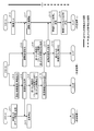
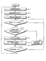
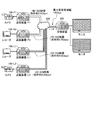
- FIG. 1 is a transition diagram showing the transition of the behavior of each device of the present embodiment.
- FIG. 2 is a diagram illustrating an example of the transition of the usage amount of the reception band of the reception device according to the present embodiment.
- FIG. 3 is a hardware configuration diagram showing an example of a schematic configuration of the network-mediated video transmission system in the present embodiment.
- FIG. 4 is a hardware configuration diagram showing an example of the configuration of the network-mediated video transmission system in the present embodiment.
- FIG. 5 is a hardware configuration diagram illustrating an example of a configuration of a network-mediated video transmission system at the time of switching transmission video in the present embodiment.
- FIG. 6 is a hardware configuration diagram illustrating an example of the configuration of a video transmission system via a network at the time of transmission video switching in the present embodiment.
- FIG. 7 is a hardware configuration diagram illustrating an example of the configuration of the transmission apparatus according to the present embodiment.
- FIG. 8 is a hardware configuration diagram illustrating an example of a configuration of the receiving device according to the present embodiment.
- FIG. 9 is a hardware configuration diagram illustrating an example of a configuration of a network-mediated video transmission system at the time of switching transmission video in the present embodiment.
- FIG. 10 is a hardware configuration diagram illustrating an example of a configuration of a network-mediated video transmission system at the time of transmission video switching in the present embodiment.
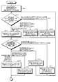
- FIG. 11A is a flowchart illustrating an example of processing in the receiving apparatus of this embodiment.
- FIG. 11B is a flowchart illustrating an example of processing in the receiving apparatus of this embodiment.
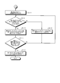
- FIG. 12 is a flowchart showing an example of processing in the transmission apparatus-F of the present embodiment.
- FIG. 13 is a flowchart illustrating an example of processing in the transmission apparatus-L of the present embodiment.
- FIG. 14 is a flowchart illustrating an example of a transmission amount adjustment process in the present embodiment.
- FIG. 15 is a hardware configuration diagram illustrating an example of the configuration of a video transmission system via a network at the time of transmission video switching in the present embodiment.
- FIG. 16 is a hardware configuration diagram illustrating an example of a configuration of a video transmission system via a network when switching transmission video in the present embodiment.
- FIG. 17A is a flowchart illustrating an example of processing in the receiving apparatus of this embodiment.
- FIG. 17B is a flowchart illustrating an example of processing in the receiving apparatus of this embodiment.
- FIG. 18 is a hardware configuration diagram illustrating an example of a configuration of a video transmission system via a network at the time of transmission video switching in the present embodiment.
- FIG. 19 is a hardware configuration diagram illustrating an example of a configuration of a video transmission system via a network at the time of transmission video switching in the present embodiment.
- FIG. 20A is a flowchart illustrating an example of processing in the receiving apparatus of this embodiment.
- FIG. 20B is a flowchart illustrating an example of processing in the receiving apparatus of this embodiment.
- FIG. 21 is a hardware configuration diagram illustrating an example of a configuration of a video transmission system via a network when switching transmission video in the present embodiment.
- FIG. 21 is a hardware configuration diagram illustrating an example of a configuration of a video transmission system via a network when switching transmission video in the present embodiment.
- FIG. 22 is a hardware configuration diagram illustrating an example of a configuration of a network-mediated video transmission system at the time of transmission video switching in the present embodiment.
- FIG. 23A is a flowchart illustrating an example of processing in the receiving apparatus of this embodiment.
- FIG. 23B is a flowchart illustrating an example of processing in the receiving apparatus of this embodiment.
- FIG. 1 is a transition diagram showing the transition of the behavior of each device of the present embodiment.
- the present embodiment schematically has the following basic features.
- the transmitting apparatus-F of the present embodiment inputs video from a camera or the like, converts the input video into IP packets, converts the IP video into IP data, and transmits the IP data to the receiving apparatus ( Step S-1).
- the transmission device-F may add a flag for identifying the beginning and / or end of the frame when converting the specification of the input video into IP data.
- the frame in the present embodiment may be a frame of a screen (that is, not a frame such as a data packet but one still image (frame) constituting a moving image).
- the transmission device-L inputs video from a camera or the like, converts the input video into IP packets, converts it into IP data, and accumulates (temporarily) IP data before transmission (step S-2).
- the process of step S-1 and the process of step S-2 may be either earlier in time or simultaneous.
- the receiving device receives the IP data transmitted from the transmitting device-F, converts the IP data into a video, and outputs the video (step S-3).
- the receiving apparatus may determine whether or not the received IP data has been received from the beginning to the end of the frame.
- the receiving device transmits a transmission stop (switch) instruction to the transmitting device-F (step S-4).
- the transmission device-F receives the transmission stop instruction transmitted from the reception device, and stops the transmission processing of the IP data to the reception device (step S-5).
- step S-6 the receiving device transmits an adjustment transmission instruction to the transmitting device-L (step S-6). Note that the process of step S-4 and the process of step S-6 may be performed earlier in time or at the same time.
- the transmitting apparatus-L starts adjusting and transmitting the IP data to the receiving apparatus (step S-7).
- the receiving device starts receiving the IP data transmitted from the transmitting device-L, and converts the IP data from the transmitting device-F until receiving IP data for one frame of the screen from the transmitting device-L.
- An image is output (step S-8).
- the receiving device determines whether or not it has received from the beginning to the end of the frame from the IP data received from the transmitting device-L, and when receiving IP data for one frame of the screen, from the transmitting device-L
- the video converted from the IP data starts to be output (step S-9). That is, after receiving one frame of the screen from the transmission device-L, the reception device outputs the video from the transmission device-L.
- the receiving apparatus may determine whether or not the received IP data has been received from the beginning to the end of the frame.
- step S-10 the reception apparatus transmits an adjustment transmission stop instruction to the transmission apparatus-L (step S-11).
- the transmitting device-L transmits the IP data to the receiving device using the full bandwidth (step S-12).
- the receiving device receives the IP data transmitted from the transmitting device-L, and continues to output the video obtained by converting the IP data from the transmitting device-L (step S-13).
- the transmission device-L converts the input video (video input) (for example, all video) into IP packets, converts them into IP data, and transmits the IP data to the reception device (step S-14). Exit.
- FIG. 2 is a diagram illustrating an example of the transition of the usage amount of the reception band of the reception device according to the present embodiment.
- ⁇ 1> indicates IP data (video data) transmitted from the transmitting apparatus-F
- ⁇ 2> indicates a transmitting apparatus- IP data (video data) adjusted and transmitted at L
- ⁇ 3> is transmitted from the transmission device-L using the entire band (including the amount accumulated in the period ⁇ 2>)
- ⁇ 4> indicates IP data (video data) transmitted from the transmission device-L.
- S-5, S-7, S-11, and S-12 in FIG. 2 show an example of the timing of each process (step) in FIG. For example, as shown in S-11 in FIG.
- the reception device adjusts the transmission amount to the transmission device-L and transmits the IP data. Send the data to instruct to stop sending. Then, the reception device finally outputs the video data transmitted from the transmission device-L.
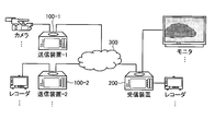
- FIG. 3 is a hardware configuration diagram showing an example of a schematic configuration of the network-mediated video transmission system in the present embodiment.
- FIG. 4 is a hardware configuration diagram showing an example of the configuration of the network-mediated video transmission system in the present embodiment.
- FIG. 5 and FIG. 6 are hardware configuration diagrams showing an example of the configuration of the network-mediated video transmission system at the time of switching the transmission video in the present embodiment.
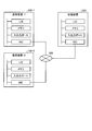
- FIG. 7 is a hardware configuration diagram illustrating an example of the configuration of the transmission device 100 according to the present embodiment.
- FIG. 8 is a hardware configuration diagram illustrating an example of the configuration of the receiving device 200 in the present embodiment.
- the video transmission system via a network schematically includes a plurality of transmission apparatuses (transmission apparatus 100-1 and transmission apparatus 100-2) and a reception apparatus 200 via a network 300.
- each device constituting the video transmission system via the network includes an LSI for converting video to IP data, an LSI for IP data transmission / reception processing, a memory for buffering IP video, and the like. It may be configured to include a storage device, an arbitrary number of input / output ports for video input / output, and a NIC (network interface) for transmitting and receiving IP data.
- the input / output port may be an SDI terminal, an HDMI (registered trademark) terminal, a display port terminal, or the like.
- a camera or a recorder is connected to the end of the input port that constitutes the input / output port, and a display (monitor), A recorder, a video storage device, or the like may be connected.
- the LSI a chip such as an FPGA or a CPU may be mounted.
- the storage device may be a RAM, an SSD, an HDD, or the like.
- NIC a twisted pair cable or an optical transceiver module such as SFP + or XFP may be used.
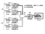
- FIG. 5 shows a video transmission system via a network configured by connecting n + m transmission devices 100 connected to a camera and a reception device 200 connected to a monitor via a network 300 so that they can communicate with each other.
- the receiving apparatus 200 receives IP data from the n transmitting apparatuses 100-F including the transmitting apparatus 100-F1 and the transmitting apparatus 100-F2 and converts the IP data received from the transmitting apparatus 100-F1 into It shows a video transmission system via a network (which outputs video based on the network).
- F is a code based on the first letter of First (since IP data (video data) is first transmitted). That is, the transmitting device 100-F is a device that first transmits a video to the receiving device 200.
- the transmission device 100-F is described as a transmission F.
- n (n is an arbitrary number greater than or equal to 1) transmitting apparatuses 100-F convert the input video to IP data and transmit it to the receiving apparatus 200. You may do it.
- the video output from the receiving device 200 in the initial state may be one of those received from the transmitting device 100-F.
- m (m is an arbitrary number greater than or equal to 1) transmission apparatuses 100-L are converting the input video into IP data and transmitting it to the reception apparatus 200. IP data may not be transmitted to the device 200.
- the receiving apparatus 200 receives the IP data from the n transmitting apparatuses 100-F, converts the IP data into videos, and outputs one video out of the n videos (the transmitting apparatus 100 in FIG. 5).
- -Video from F1 may be output. It should be noted that which video the receiving apparatus 200 outputs is arbitrary.
- the receiving apparatus 200 may use more than half of the reception band by the IP data transmitted from the transmitting apparatus 100-F. Further, the receiving apparatus 200 may continue to output any one video out of the frames (videos) received from the transmitting apparatus 100-F1 or the transmitting apparatus 100-F2.
- FIG. 6 illustrates a video transmission system via a network configured by connecting n + m transmission apparatuses 100 connected to a camera and a reception apparatus 200 connected to a monitor via a network 300 so that they can communicate with each other.
- the receiving device 200 receives IP data from the m transmitting devices 100-L including the transmitting device 100-L1 and the transmitting device 100-L2, and receives the video received from the transmitting device 100-L1).
- the video transmission system via the network (after switching) is output.
- L is a code based on the initial of Last (since IP data (video data) is finally transmitted). That is, the transmitting device 100-L is a device that finally transmits video to the receiving device 200.
- the transmission device 100-L is described as the transmission L.
- the receiving device 200 may determine to output video from any one of the transmitting device 100-L1 and the transmitting device 100-L2.
- n is an arbitrary number greater than or equal to 1
- transmitter apparatuses 100-F perform IP data transmission processing to receiver apparatus 200. You may stop.
- m is an arbitrary number greater than or equal to 1
- transmitting apparatus 100-L converts the input video to IP data and transmits it to receiving apparatus 200. May be.
- the video output from the receiving device 200 in the final state (after switching) is a video based on IP data transmitted from m transmitting devices 100-L (m is an arbitrary number of 1 or more). One of them (in FIG. 6, a video from the transmitting device 100-L1) may be used.
- the receiving apparatus 200 receives IP data from m transmitting apparatuses 100-L different from the n transmitting apparatuses 100-F, and out of the m images. One video image may be output. Note that the receiving apparatus 200 can arbitrarily select which transmitting apparatus 100-L to finally output the video received from the transmitting apparatus 100-L, but may select it in advance before the video switching process.
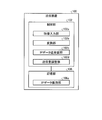
- the transmission device 100 includes at least a control unit 102 and a storage unit 106.
- the storage unit 106 stores various databases, tables, and / or files.
- the storage unit 106 is a storage unit, and for example, a memory such as a RAM / ROM, a fixed disk device such as a hard disk, a flexible disk, and / or an optical disk can be used.
- the storage unit 106 stores computer programs and the like for giving instructions to a CPU (Central Processing Unit) and performing various processes.
- CPU Central Processing Unit
- the IP data holding unit 106a holds (stores) IP data.
- the IP data holding unit 106 a may hold IP data that has not been transmitted to the receiving apparatus 200 by adjustment by the control unit 102. That is, the IP data holding unit 106a may be a memory that holds IP data before transmission.
- the transmission device 100 may further include an input / output interface unit that connects an external device (camera, recorder, or the like) and / or the network 300 and the control unit 102.
- the input / output interface unit may be an input / output port or a NIC.
- the transmission device 100 may further include an input / output unit that performs input / output (I / O) of data or commands.
- the input / output unit may be, for example, a key input unit, a touch panel, a control pad (for example, a touch pad and a game pad), a mouse, a keyboard, and a microphone.
- the input / output unit may be display means for displaying a display screen of an application or the like (for example, a display, a monitor, a touch panel, or the like including a liquid crystal or an organic EL).
- the input / output unit may be a sound output unit (for example, a speaker or the like) that outputs sound information as sound.
- control unit 102 includes a CPU and the like that control the transmission apparatus 100 in an integrated manner.
- the control unit 102 has an internal memory for storing a control program, a program defining various processing procedures, and necessary data, and performs information processing for executing various processes based on these programs.
- control unit 102 roughly includes a video input unit 102a, a conversion unit 102b, an IP data transmission / reception unit 102c, and a transmission amount adjustment unit 102d.
- the video input unit 102a inputs video.
- the video input unit 102a may input a video transmitted from an external device.
- the video input unit 102a may input video transmitted from an external device via an arbitrary number of input / output ports.
- the video input unit 102a may be included in any number of input / output ports.
- the conversion unit 102b converts the video into IP data.
- the conversion unit 102b may add identification information (flag) for identifying the beginning or end of the frame to the converted IP data.
- the conversion unit 102b may convert IP data into video.
- the conversion unit 102b may be included in the LSI.
- the IP data transmission / reception unit 102c transmits / receives IP data.
- the IP data transmitting / receiving unit 102c may transmit the IP data to the receiving device 200.
- the IP data transmission / reception unit 102c may transmit the IP data to the receiving device 200 based on the adjustment transmission stop instruction data instructing to transmit the IP data without adjusting.
- the IP data transmission / reception unit 102c may be included in the NIC.
- the transmission amount adjustment unit 102d adjusts the transmission amount.
- the transmission amount adjusting unit 102d may adjust the amount of IP data transmitted to the receiving apparatus 200 in accordance with the empty bandwidth of the receiving apparatus 200. Further, the transmission amount adjusting unit 102d adjusts the amount of IP data to be transmitted to the receiving apparatus 200 according to the empty band of the receiving apparatus 200 based on the empty capacity information regarding the empty capacity of the receiving band of the receiving apparatus 200. Also good. Further, the transmission amount adjustment unit 102d may be included in the LSI. Thus, the transmission amount adjustment unit 102d may perform a transmission amount adjustment process for adjusting the transmission amount.
- the receiving device 200 includes at least a control unit 202 and a storage unit 206.
- the storage unit 206 stores various databases, tables, and / or files.
- the storage unit 206 is storage means, and for example, a memory such as a RAM / ROM, a fixed disk device such as a hard disk, a flexible disk, and / or an optical disk can be used.
- the storage unit 206 stores computer programs and the like for giving instructions to the CPU and performing various processes.
- the IP data holding unit 206a holds (stores) IP data.
- the IP data holding unit 206a may be a memory or the like that holds the received IP data.
- the receiving device 200 may further include an input / output interface unit that connects an external device (such as a monitor, a recorder, or a video storage device) and / or the network 300 and the control unit 202.
- the input / output interface unit may be an input / output port or a NIC.
- the receiving apparatus 200 may further include an input / output unit that performs input / output (I / O) of data or commands.
- the input / output unit may be, for example, a key input unit, a touch panel, a control pad (for example, a touch pad and a game pad), a mouse, a keyboard, and a microphone.
- the input / output unit may be display means for displaying a display screen of an application or the like (for example, a display, a monitor, a touch panel, or the like including a liquid crystal or an organic EL).
- the input / output unit may be a sound output unit (for example, a speaker or the like) that outputs sound information as sound.
- the control unit 202 includes a CPU that controls the receiving device 200 in an integrated manner.
- the control unit 202 has an internal memory for storing a control program, a program defining various processing procedures, and necessary data, and performs information processing for executing various processes based on these programs.
- control unit 202 is roughly divided into an IP data transmission / reception unit 202a, an instruction transmission unit 202b, a frame start / end determination unit 202c, a next output frame determination unit 202d, a conversion unit 202e, and a video output unit 202f. Is provided.
- the IP data transmission / reception unit 202a transmits / receives IP data.
- the IP data transmission / reception unit 202a may receive the IP data transmitted from the transmission device 100.
- the IP data transmission / reception unit 202a may be included in the NIC.
- the instruction transmission unit 202b transmits instruction data.
- the instruction transmission unit 202b adjusts transmission start instruction data for instructing to start transmission after adjusting the IP data, including the free capacity information related to the free capacity of the reception band. You may transmit to the transmitter 100 which is not a transmission source.
- the instruction transmission unit 202b may transmit transmission stop instruction data instructing to stop transmission of IP data to the transmission apparatus 100 that is a transmission source.
- the instruction transmission unit 202b may transmit adjusted transmission stop instruction data for instructing transmission without adjusting IP data to the transmission apparatus 100 that is not the transmission source of the frame output in the reception apparatus 200.
- the instruction transmission unit 202b may perform an IP data transmission stop instruction, an adjustment transmission start instruction, an adjustment transmission stop instruction, and the like, and a transmission behavior instruction for manipulating the behavior of the transmission apparatus 100.
- the frame head / end discriminator 202c identifies the IP data at the head of the frame and the IP data at the end of the frame.
- the frame start / end determination unit 202c based on identification information (flag) identifying the start or end of the frame added to the IP data, the frame start IP data, the frame end IP data, May be identified. That is, the frame start / end determination unit 202c may determine whether the start data or the last data of the frame is the IP data. Further, the frame head / end determination unit 202c may be included in the LSI.
- the next output frame determination unit 202d determines the next frame to be output according to the usage amount of the reception band and / or the amount of IP data transmitted from the plurality of transmission devices 100.
- the next output frame determination unit 202d determines the frame obtained by converting the IP data as If the frame to be output is determined as the next frame to be output after the output of the output frame, and the amount of IP data is less than the threshold, the output frame is again output to the next frame after the output of the output frame.
- next output frame determination unit 202d may further determine a frame to be output next based on the identification by the frame head / end determination unit 202c.
- the threshold may be for one frame. That is, the next output frame determination unit 202d may determine a frame to be output next in accordance with the received IP data amount and / or the received bandwidth usage amount. Further, the next output frame determination unit 202d may be included in the LSI. As described above, the next output frame determination unit 202d determines the next frame to be output in accordance with the usage amount of the reception band of the reception device 200 and / or the amount of IP data received from the plurality of transmission devices 100. An output frame determination process may be performed.
- the conversion unit 202e converts IP data into video.
- the conversion unit 202e may convert the video into IP data.
- the conversion unit 202e may be included in the LSI.
- the video output unit 202f outputs video.
- the video output unit 202f may output the video via the input / output unit.
- the video output unit 202f may be included in any number of input / output ports.
- FIG. 9 and FIG. 10 are hardware configuration diagrams showing an example of the configuration of a network-mediated video transmission system at the time of transmission video switching in the present embodiment.
- FIG. 9 shows an initial state at the time of transmission video switching in the case of one transmission device 100-F and one transmission device 100-L.
- the transmission F transmits 3G-SDI video (capacity of about 7 Gbps in total) input from the camera to the reception device 200. Since the reception device 200 has one transmission F, the video from the transmission F is transmitted. Output.
- the reception bandwidth of the reception device 200 may be used for 7 Gbps out of 10 Gbps.
- SFP + may be used as the NIC, and the transmission / reception bandwidth capacity may be 10 Gbps.
- FIG. 10 shows the final state at the time of transmission video switching when there is one transmission device 100-F and one transmission device 100-L.
- the transmission L transmits 3G-SDI video (capacity of about 7 Gbps in total) input from the recorder to the reception device 200, and the reception device 200 switches the output video to the video from the transmission L.
- 3G-SDI video capacity of about 7 Gbps in total
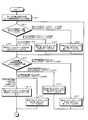
- FIG. 11 is a flowchart illustrating an example of processing in the receiving apparatus 200 of the present embodiment.
- the transmission F transmits IP data (video data) to the receiving apparatus 200 using the reception band of about 7 Gbps, and the receiving apparatus 200 outputs the received IP data as video.
- the instruction transmission unit 202b transmits transmission stop instruction data for instructing to stop transmission of IP data to the transmission F that is a transmission source, and receives IP data including free capacity information regarding the free capacity of the reception band (3 Gbps).
- the adjusted transmission start instruction data for instructing to start transmission after adjustment is transmitted to the transmission L which is not the transmission source of the frame output in the receiving apparatus 200 (step SA-1).
- the receiving apparatus 200 may transmit data instructing to start transmitting IP data by adjusting the transmission amount to the transmission L.
- the instruction data may be transmitted including information on the free capacity of the reception band of the reception device 200. Further, the receiving apparatus 200 may transmit data instructing to stop transmission to the transmission F.
- the transmission stop instruction data transmission and the adjustment transmission start instruction data transmission may be either first or simultaneously.
- the next output frame determination unit 202d receives the IP data amount (video data amount, that is, the received data amount) received from the transmission L and the IP data amount (video data amount) received from the transmission F every arbitrary time.
- the arbitrary time may be, for example, 32 ms (assuming a video format of 30 fps).
- next output frame determination unit 202d determines that the amount of received data from the transmission L is less than the threshold (for one frame) and the reception data from the transmission F is equal to or greater than the threshold (for one frame)
- the next output frame determination unit 202d After the output frame is output, it is determined that the frame from the transmission F is output, and the video output unit 202f outputs the frame from the transmission F after outputting the currently output frame (step SA-3).
- step SA-3 proceeds to step SA-2. That is, the video output unit 202f may output the video from the transmission F because IP data equal to or greater than the threshold is not transmitted from the transmission L.
- the threshold value of the received data may vary depending on the data amount in an arbitrary number of frames such as one frame or two frames, and / or the format of the video (eg, about 30,000,000 bytes for HD 720 / 60p ( If the transfer rate is 10 Gbps, it takes 2.64 ms for transmission), or if it is 3 GB Dual Link 1080 / 23.98p, about 16506000 bytes (for transfer rate of 10 Gbps, it takes 13.2 ms)).
- the video output unit 202f may output the video (frame) converted from the IP data (received data) by the conversion unit 202e.
- the next output frame determination unit 202d determines that the received data from the transmission F is less than the threshold (for one frame) and the amount of reception data from the transmission L is less than the threshold (for one frame)
- the current output After outputting the current frame, it is determined to output the same frame (the last frame received from the transmission F) as the previous output frame, and the video output unit 202f outputs the currently output frame and then from the transmission F.
- the last frame received is output (step SA-4), and the process proceeds to step SA-2. That is, the video output unit 202f outputs the previous output because there is no video to be newly output when the IP data is not transmitted from the transmission L above the threshold and the reception data from the transmission F is also transmitted below the threshold. May output the same.
- next output frame determination unit 202d determines that the amount of data received from the transmission L is equal to or greater than the threshold (for one frame)
- the next output frame determination unit 202d determines to output the frame from the transmission L after outputting the currently output frame.
- the video output unit 202f outputs the frame from the transmission L after outputting the currently output frame (step SA-5). That is, since IP data equal to or greater than the threshold value is transmitted from the transmission L, the video output unit 202f may output the transmission L video from the next time.
- the next output frame determination unit 202d determines the reception band usage amount of the reception device 200 and the IP data amount (video data amount) received from the transmission L at arbitrary time intervals (step SA-6).
- the next output frame determination unit 202d outputs the currently output frame when it is determined that the reception band usage is equal to or greater than the threshold (5 Gbps) and the received data from the transmission L is equal to or greater than the threshold (there is one frame). Thereafter, it is determined that the frame from the transmission L is output, and the video output unit 202f outputs the frame from the transmission L after outputting the currently output frame (step SA-7), and the processing is performed at step SA-6.
- the video output unit 202f can receive the new frame that is currently output from the transmission L One frame may be output.
- the control unit 202 can receive a new frame from the transmission L for one frame. May be output.
- the threshold of the reception band usage amount may be a variable capacity less than half of the band (for example, 5 Gbps or 4 Gbps when the total amount is 10 Gbps).
- next output frame determination unit 202d outputs the current output when the reception band usage amount of the reception device 200 is equal to or greater than the threshold (5 Gbps) and the received data from the transmission L is less than the threshold (no one frame).
- the video output unit 202f outputs the same frame as the previously output frame after outputting the currently output frame (step SA-). 8) The process proceeds to step SA-6. That is, the video output unit 202f is not able to receive one frame from the transmission L when the reception band usage amount is equal to or greater than the threshold, the transmission data from the transmission F is still received, and the band is being compressed. The same frame may be output.
- next output frame determination unit 202d outputs the current output when the reception band usage amount of the reception device 200 is less than the threshold (5 Gbps) and the reception data from the transmission L is equal to or greater than the threshold (there is one frame).
- the video output unit 202f outputs the frame from the transmission L and outputs the frame from the transmission L (step SA-9). ), The process proceeds to step SA-11. That is, the video output unit 202f has received a new frame from the transmission L when the reception bandwidth usage is less than the threshold, the transmission data from the transmission F cannot be received, and the bandwidth becomes empty. It may be output.
- next output frame determination unit 202d outputs the current output when the reception band usage amount of the receiving apparatus 200 is less than the threshold (5 Gbps) and the received data from the transmission L is less than the threshold (for one frame). After outputting the frame, it is determined that the same frame as the previously output frame is output again, and after outputting the currently output frame, the video output unit 202f outputs the same frame as the previously output frame again (step SA- 10). That is, the video output unit 202f uses the reception bandwidth less than the threshold, and the transmission data from the transmission F has not been received and the bandwidth has been vacated. May be output.
- the instruction transmission unit 202b transmits adjustment transmission stop instruction (adjustment release instruction) data for instructing transmission without adjusting the IP data to the transmission L (step SA-11). That is, the instruction transmission unit 202b may transmit data instructing the transmission L to adjust transmission amount and stop transmitting IP data.
- adjustment transmission stop instruction adjustment release instruction
- next output frame determination unit 202d determines whether or not the IP data amount (video data amount) received from the transmission L is equal to one frame every arbitrary time (step SA-12).
- the next output frame determination unit 202d may further determine whether or not the amount of IP data received from the transmission L is one frame based on the identification by the frame head / end determination unit 202c.
- next output frame determination unit 202d determines that the received data from the transmission L is less than the threshold (one frame), that is, not one frame (step SA-12: No)
- the next output frame determination unit 202d outputs the current data. After outputting the current frame, it is determined that the same frame as the previously output frame is output again, and the video output unit 202f outputs the same frame as the previously output frame after outputting the currently output frame (step S1). SA-13), the process proceeds to step SA-12.
- next output frame determination unit 202d determines that the received data from the transmission L is equal to or greater than the threshold (one frame), that is, one frame (step SA-12: Yes)
- the next output frame determination unit 202d outputs the current data.
- the video output unit 202f outputs the new frame from the transmission L after outputting the currently output frame (step SA). -14).
- next output frame determination unit 202d determines whether or not new frames received from the transmission L can be output continuously for the output frame 10 times or more (step SA-15).
- the number of determinations may be a variable arbitrary number.
- step SA-15 If the next output frame determination unit 202d determines that the new frames received from the transmission L have not been output continuously for the output frame 10 times or more (step SA-15: No), the process proceeds to step SA- 12.
- next output frame determination unit 202d determines that the new frame received from the transmission L has been output continuously for the output frame ten times or more (step SA-15: Yes)
- the frame received from the transmission L is determined.
- the video output unit 202f continues to output the frame received from the transmission L (step SA-16), and ends the process. That is, the receiving apparatus 200 may finally output the video from the transmission L.
- the NIC is added and the bandwidth is increased, or the processing of reducing the video data itself by performing the compression processing is not performed. Switching is possible.
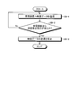
- FIG. 12 is a flowchart illustrating an example of processing in the transmission device 100-F of the present embodiment.
- IP data is transmitted from the transmission F to the reception device 200, and the reception device 200 continues to output the video (frame) received from the transmission F (the reception bandwidth of the reception device 200 is 7 Gbps).
- the IP data transmitting / receiving unit 102c transmits IP data (video data) to the receiving apparatus 200 (step SB-1).
- the IP data transmission / reception unit 102c may transmit the IP data obtained by converting the video input by the video input unit 102a by the conversion unit 102b to the reception device 200.
- the conversion unit 102b may add identification information (flag) for identifying the beginning or end of the frame to the converted IP data. That is, the transmission F may convert the input video into IP data and continue to transmit the IP data to the receiving device 200.
- the IP data transmission / reception unit 102c determines whether or not transmission stop instruction data instructing to stop transmission of IP data has been received from the receiving apparatus 200 (step SB-2).
- step SB-2 If it is determined that the IP data transmission / reception unit 102c has not received transmission stop instruction data for instructing to stop transmission of IP data from the receiving device 200 (step SB-2: No), the process proceeds to step SB-1. To migrate.
- the IP data transmitting / receiving unit 102c determines that it has received transmission stop instruction data instructing to stop transmission of IP data from the receiving device 200 (step SB-2: Yes)
- the IP data (video data) is transmitted to the receiving device. ) Is stopped (step SB-3), and the process is terminated. That is, the transmission F may receive data instructing to stop transmission of IP data from the receiving apparatus 200 and stop transmitting IP data to the receiving apparatus 200.
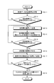
- FIG. 13 is a flowchart illustrating an example of processing in the transmission device 100-L of the present embodiment.
- IP data is transmitted from the transmission F to the reception device 200, and the reception device 200 continues to output the video (frame) received from the transmission F (the reception bandwidth of the reception device 200 is 7 Gbps).
- the IP data transmission / reception unit 102c maintains an IP data (video data) transmission stop state to the receiving apparatus 200, and adjusts the IP data from the receiving apparatus 200 to instruct to start transmission. Wait until transmission start instruction data is received (step SC-1). That is, the transmission L may stand by until receiving data instructing to transmit by adjusting the transmission amount from the receiving device 200.
- the transmission amount adjusting unit 102d determines whether or not the adjusted transmission start instruction (adjusted transmission instruction) data for instructing to start transmission after adjusting the IP data from the receiving apparatus 200 has been received (step). SC-2).
- step SC-2 determines that the adjusted transmission start instruction (adjusted transmission instruction) data for instructing to start transmission after adjusting the IP data is not received from the receiving apparatus 200 (step SC-2: No), the process proceeds to step SC-1.
- the transmission amount adjusting unit 102d determines that the adjusted transmission start instruction (adjusted transmission instruction) data instructing to start transmission after adjusting the IP data from the receiving apparatus 200 is received (step SC-2: Yes). Then, the transmission amount is adjusted, and the IP data transmitting / receiving unit 102c transmits the IP data of the transmission amount adjusted by the transmission amount adjusting unit 102d to the receiving device 200 (step SC-3).
- the transmission amount adjusting unit 102d may adjust the amount of IP data transmitted to the receiving apparatus 200 in accordance with the empty bandwidth of the receiving apparatus 200.
- the transmission amount adjusting unit 102d adjusts the amount of IP data to be transmitted to the receiving apparatus 200 according to the empty band of the receiving apparatus 200 based on the empty capacity information regarding the empty capacity of the receiving band of the receiving apparatus 200. Also good. That is, the transmission L obtains information on the free capacity of the reception band of the reception device 200 from the received adjustment transmission start instruction data, converts the input video into IP data, and adjusts the transmission amount according to the free capacity. And the IP data may be transmitted to the receiving apparatus 200.
- the transmission amount adjusting unit 102d stores (holds) the IP data (video data) accumulated as a result of adjusting the transmission amount in the IP data holding unit 106a (step SC-4). That is, the control unit 102 may hold the IP data accumulated as a result of the adjustment in the memory.
- the transmission amount adjustment unit 102d determines whether or not adjustment transmission stop instruction (adjustment release instruction) data instructing to transmit the IP data without adjustment from the receiving apparatus 200 has been received (step has been received) (step S1). SC-5).
- step SC-5 when the transmission amount adjusting unit 102d determines that it has not received adjustment transmission stop instruction (adjustment release instruction) data instructing transmission from the receiving apparatus 200 without adjusting IP data (step SC-5: No), the process proceeds to step SC-3. That is, the transmission L performs the processes of Step SC-3 and Step SC-4 until receiving the adjustment transmission stop instruction data for instructing to stop transmitting the IP data by adjusting the transmission amount from the receiving apparatus 200. It may be repeated.
- adjustment transmission stop instruction adjustment release instruction
- step SC-5 when the transmission amount adjusting unit 102d determines that the adjustment transmission stop instruction (adjustment release instruction) data instructing to transmit the IP data without adjusting is received from the receiving apparatus 200 (step SC-5: Yes). The transmission amount adjustment is stopped (step SC-6).
- the IP data transmitting / receiving unit 102c transmits the IP data to the receiving device 200 using all the usable bands (step SC-7).
- the IP data transmission / reception unit 102c may transmit the IP data using the full bandwidth until there is no more data stored in the IP data holding unit 106a (memory).
- the IP data transmitting / receiving unit 102c determines whether or not the IP data (video data) stored (accumulated) in the IP data holding unit 106a has been lost (step SC-8).
- step SC-8 No
- the process proceeds to step SC-7. To migrate.
- the IP data transmission / reception unit 102c determines that the IP data (video data) stored (accumulated) in the IP data holding unit 106a has been lost (step SC-8: Yes)
- the IP data transmission / reception unit 102c is input by the video input unit 102a.
- the IP data continues to be transmitted to the receiving apparatus 200 for the amount of video data (step SC-9), and the process ends. That is, the transmission L may convert the input video into IP data and transmit it to the receiving device 200.
- the transmission device 100-L that transmits IP data later adjusts the transmission amount, but without discarding the input video after starting to transmit the video, Video can be transmitted to the receiving device 200.
- FIG. 14 is a flowchart illustrating an example of a transmission amount adjustment process in the present embodiment.
- the transmission amount adjusting unit 102d sets the transmission limit amount based on the empty capacity information related to the empty capacity of the reception band of the receiving apparatus 200 transmitted from the receiving apparatus 200 (step SD-1). . That is, the transmission amount adjusting unit 102d may set the free capacity information (for example, 3G (bit), 1.5G (bit), or 10G (bit)) regarding the free capacity of the reception band of the receiving device 200.
- the free capacity information for example, 3G (bit), 1.5G (bit), or 10G (bit)
- the transmission amount adjusting unit 102d resets the accumulated transmission amount to the receiving apparatus 200 to 0 (step SD-2).
- the transmission amount adjusting unit 102d acquires the current time (step SD-3).
- the transmission amount adjusting unit 102d determines whether there is IP data (IP packet) to be transmitted to the receiving apparatus 200 (step SD-4).
- step SD-4 When determining that there is no IP packet to be transmitted to the receiving apparatus 200 (step SD-4: No), the transmission amount adjusting unit 102d stands by until an IP packet to be transmitted arrives.
- the transmission limit amount may be an arbitrarily set size (for example, 3 Gbps or 10 Gbps), or may be set for each process.
- step SD-5 No
- Step SD-5 Yes
- the IP packet is transmitted to the receiving apparatus 200 (Step SD-7).
- the transmission amount adjustment unit 102d adds the size of the IP packet transmitted by the IP data transmission / reception unit 102c in step SD-7 to the cumulative transmission amount (step SD-8).
- the predetermined time may be an arbitrarily settable time (for example, 10 ⁇ sec, 1 msec, 1 sec, etc.).
- step SD-9 If the transmission amount adjusting unit 102d determines that the predetermined time or more has elapsed (step SD-9: Yes), it resets the transmission limit amount, the accumulated transmission amount, and the time, and shifts the processing to step SD-1.
- step SD-9 determines that the predetermined time or more has not elapsed (step SD-9: No)
- the transmission amount adjusting unit 102d may wait for the next transmission IP packet.
- the transmission amount is adjusted by checking the data amount (accumulated transmission amount) transmitted at a predetermined time each time an IP packet is transmitted, and if the transmission amount specified at the predetermined time is exceeded, transmission processing is not performed. . You may implement
- FIG. 15 and FIG. 16 are hardware configuration diagrams showing an example of the configuration of the network-mediated video transmission system at the time of transmission video switching in the present embodiment.
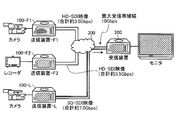
- FIG. 15 shows an initial state at the time of transmission video switching when there are two transmission apparatuses 100-F and one transmission apparatus 100-L.
- the transmission F1 transmits HD-SDI video (capacity of about 3.5 Gbps in total) input from the camera to the receiving device 200
- the transmission F2 transmits HD-SDI video (total of about 3 in total) from the recorder. .5 Gbps capacity) is transmitted to the receiving apparatus 200. Since the receiving apparatus 200 has two transmission Fs, the receiving apparatus 200 outputs video from the transmission F1 and / or the transmission F2.
- the reception bandwidth of the reception device 200 may be used for 7 Gbps out of 10 Gbps.
- XFP may be used as the NIC, and the transmission / reception bandwidth capacity may be 10 Gbps.
- the receiving apparatus 200 may divide the video from the transmission L1 and the video from the transmission L2 and output them to a monitor or the like.
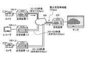
- FIG. 16 shows the final state at the time of transmission video switching in the case where there are two transmission devices 100-F and one transmission device 100-L.
- the sending L transmits 3G-SDI video (capacity of about 7 Gbps in total) input from the camera to the receiving device 200, and the receiving device 200 switches the output video to the video from the sending L.
- 3G-SDI video capacity of about 7 Gbps in total
- FIG. 17 is a flowchart illustrating an example of processing in the receiving apparatus 200 of the present embodiment.
- transmission F1 and / or transmission F2 uses the reception band of about 7 Gbps to transmit IP data (video data) to the reception device 200, and the IP data received by the reception device 200 as video.
- the instruction transmission unit 202b transmits transmission stop instruction data for instructing to stop transmission of IP data to the transmission F1 and the transmission F2 that are transmission sources, and the free capacity information regarding the free capacity of the reception band
- the adjusted transmission start instruction data for instructing to start transmission after adjusting the IP data (to 3 Gbps) is transmitted to the transmission L that is not the transmission source of the frame output in the receiving apparatus 200 (step SE-1) .
- the instruction data may be transmitted including information on the free capacity of the reception band of the reception device 200.
- transmission F1 and transmission F2 when there are a plurality of transmission apparatuses 100-F (transmission F1 and transmission F2) as in the present embodiment, it may be instructed to adjust the transmission amount to a capacity obtained by dividing the empty capacity by the number of units.
- the transmission stop instruction data transmission and the adjustment transmission start instruction data transmission may be either first or simultaneously.
- the next output frame determination unit 202d receives the IP data amount (video data amount, that is, the received data amount) received from the transmission L and the IP data amount (video data) received from the transmission F1 and the transmission F2 at arbitrary time intervals.
- Data amount is determined (step SE-2).
- the arbitrary time may be 41 ms (assuming a video format of 24 fps), for example.
- next output frame determination unit 202d determines that the amount of received data from the transmission L is less than the threshold (for one frame) and that the reception data from the transmission F1 and / or the transmission F2 is equal to or greater than the threshold (for one frame)
- the video output unit 202f outputs the currently output frame, and then transmits the transmission F1 and / or the transmission F2.
- step SE-3 the video output unit 202f may output the video from the transmission F1 and / or the transmission F2 because IP data equal to or greater than the threshold is not transmitted from the transmission L.
- the video output unit 202f may output the video (frame) converted from the IP data (received data) by the conversion unit 202e.
- next output frame determination unit 202d determines that the received data from the transmission F1 and the transmission F2 is less than the threshold (for one frame) and the amount of received data from the transmission L is less than the threshold (no one frame)
- it is determined to output the same frame as the previously output frame (the last frame received from the transmission F1 and / or the transmission F2), and the video output unit 202f is currently outputting
- the last frame received from transmission F1 and / or transmission F2 is output (step SE-4), and the process proceeds to step SE-2.
- the video output unit 202f when no IP data is transmitted from the transmission L over the threshold value and the reception data from the transmission F1 and the transmission F2 is also transmitted less than the threshold value, there is no new video to be output. You may output the same output.
- next output frame determination unit 202d determines that the amount of data received from the transmission L is equal to or greater than the threshold (for one frame)
- the next output frame determination unit 202d determines to output the frame from the transmission L after outputting the currently output frame.
- the video output unit 202f outputs the frame from the transmission L after outputting the currently output frame (step SE-5). That is, since IP data equal to or greater than the threshold value is transmitted from the transmission L, the video output unit 202f may output the transmission L video from the next time.
- the next output frame determination unit 202d determines the reception band usage amount of the reception device 200 and the IP data amount (video data amount) received from the transmission L at arbitrary intervals (step SE-6).
- the next output frame determination unit 202d outputs the currently output frame when it is determined that the reception band usage is equal to or greater than the threshold (4 Gbps) and the received data from the transmission L is equal to or greater than the threshold (there is one frame). Thereafter, it is determined to output a frame from the transmission L, and the video output unit 202f outputs a frame from the transmission L after outputting the currently output frame (step SE-7), and the processing is performed in step SE-6.
- the video output unit 202f can receive the new frame that is currently output from the transmission L One frame may be output. In this way, the control unit 202 can receive a new one frame transmission L from the transmission F1 and / or the transmission F2 when the reception band usage is equal to or greater than the threshold and the transmission data is still being compressed. A new frame may be output.
- next output frame determination unit 202d outputs the current output when the reception band usage amount of the receiving apparatus 200 is equal to or greater than the threshold (4 Gbps) and the received data from the transmission L is less than the threshold (no one frame).
- the video output unit 202f outputs the same frame as the previously output frame after outputting the current output frame (step SE-). 8) The process proceeds to step SE-6.
- the video output unit 202f can receive one frame from the transmission L when the reception band usage is equal to or greater than the threshold value and the transmission data from the transmission F1 and / or the transmission F2 still arrives and the band is being compressed. The same frame as the previous time may be output.
- next output frame determination unit 202d outputs the current output when the reception band usage amount of the reception device 200 is less than the threshold (4 Gbps) and the received data from the transmission L is equal to or greater than the threshold (there is one frame).
- the video output unit 202f outputs the frame from the transmission L after outputting the currently output frame (step SE-9). )
- the process proceeds to step SE-11. That is, the video output unit 202f is able to receive a new frame from the transmission L when the reception bandwidth usage is less than the threshold, the transmission data from the transmission F1 and the transmission F2 cannot be received, and the bandwidth becomes free. A new frame may be output.
- next output frame determination unit 202d outputs the current output when the reception band usage amount of the receiving apparatus 200 is less than the threshold (4 Gbps) and the received data from the transmission L is less than the threshold (for one frame). After outputting the frame, it is determined that the same frame as the previously output frame is output again, and the video output unit 202f outputs the same frame as the previously output frame after outputting the currently output frame (step SE-). 10). That is, the video output unit 202f uses the reception bandwidth less than the threshold value, and the transmission data from the transmission F1 and the transmission F2 has not been received and the bandwidth has been vacated. The same frame may be output.
- the instruction transmission unit 202b transmits adjustment transmission stop instruction (adjustment release instruction) data for instructing transmission without adjusting the IP data to the transmission L (step SE-11).
- next output frame determination unit 202d determines whether or not the IP data amount (video data amount) received from the transmission L is equal to one frame every arbitrary time (step SE-12).
- the next output frame determination unit 202d may further determine whether or not the amount of IP data received from the transmission L is one frame based on the identification by the frame head / end determination unit 202c.
- next output frame determining unit 202d determines that the received data from the transmission L is less than the threshold (one frame), that is, not one frame (step SE-12: No)
- the next output frame determining unit 202d outputs the current data. After outputting the current frame, it is determined that the same frame as the previously output frame is output again, and the video output unit 202f outputs the same frame as the previously output frame after outputting the currently output frame (step S1). SE-13), The process proceeds to step SE-12.
- next output frame determination unit 202d determines that the received data from the transmission L is equal to or greater than the threshold (one frame), that is, one frame (step SE-12: Yes)
- the next output frame determination unit 202d outputs the current data.
- the video output unit 202f outputs a new frame from the transmission L after outputting the currently output frame (step SE). -14).
- next output frame determination unit 202d determines whether or not new frames received from the transmission L can be output continuously for the output frame 10 times or more (step SE-15).
- step SE-15 No If the next output frame determination unit 202d determines that the new frame received from the transmission L has not been output continuously for the output frame 10 times or more (step SE-15: No), the process proceeds to step SE- 12.
- next output frame determination unit 202d determines that the new frames received from the transmission L can be output continuously for the output frame 10 times or more (step SE-15: Yes)
- the frame received from the transmission L is determined.
- the video output unit 202f continues to output the frame received from the transmission L (step SE-16), and ends the process.
- step SE-16 ends the process.
- output video can be switched without adding NICs to increase the bandwidth or performing compression processing to reduce the video data itself. It becomes possible.
- the transmission L for transmitting IP data later adjusts the transmission amount. However, all of the video transmitted to the receiving device 200 is discarded without discarding the video input after the video transmission starts. Can be sent.
- processing in the transmission apparatus 100-F and the transmission apparatus 100-L in the second embodiment is the same as the processing in the transmission apparatus 100-F and the transmission apparatus 100-L in the first embodiment illustrated in FIGS. Description is omitted.
- FIGS. 18 and FIG. 19 are hardware configuration diagrams showing an example of the configuration of a network-mediated video transmission system at the time of transmission video switching in the present embodiment.
- FIG. 18 shows an initial state at the time of transmission video switching in the case of one transmission device 100-F and two transmission devices 100-L.
- the transmission F transmits 3G-SDI video (capacity of about 7 Gbps in total) input from the camera to the reception device 200. Since the reception device 200 has one transmission F, the video from the transmission F is transmitted. Output.
- the reception bandwidth of the reception device 200 may be used for 7 Gbps out of 10 Gbps.
- SFP + may be used as the NIC, and the transmission / reception bandwidth capacity may be 10 Gbps.
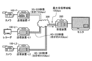
- FIG. 19 shows a final state at the time of transmission video switching in the case where there is one transmission device 100-F and two transmission devices 100-L.
- the transmission L1 transmits HD-SDI video (total capacity of about 4.0 Gbps) input from the recorder to the receiving device 200
- the transmission L2 transmits HD-SDI video (total of about 4 total) from the camera. .0 Gbps) to the receiving device 200
- the receiving device 200 switches the output video to the video from the sending L1 and / or sending L2.
- the receiving apparatus 200 may superimpose the video from the transmission L2 on the video from the transmission L1 using a corner wipe and output the video to the monitor or the like.
- FIG. 20 is a flowchart illustrating an example of processing in the receiving apparatus 200 of the present embodiment.
- the transmission F transmits IP data (video data) to the receiving apparatus 200 using a reception band of about 7 Gbps, and the receiving apparatus 200 outputs the received IP data as video.
- the instruction transmission unit 202b transmits transmission stop instruction data for instructing to stop transmission of IP data to the transmission F that is the transmission source, and receives the IP data including the free capacity information regarding the free capacity of the reception band (1).
- the adjusted transmission start instruction data for instructing to start transmission after adjusting (.5 Gbps) is transmitted to the transmission L1 and the transmission L2 that are not the transmission source of the frame output in the receiving apparatus 200 (step SF-1). That is, the receiving apparatus 200 may transmit data instructing to start transmitting IP data by adjusting the transmission amount to the transmission L1 and the transmission L2.
- the transmission stop instruction data transmission and the adjustment transmission start instruction data transmission may be either first or simultaneously.
- the next output frame determination unit 202d receives the IP data amount (image data amount, that is, the received data amount) received from the transmission L1 and the transmission L2 and the IP data amount (video image) received from the transmission F at arbitrary time intervals.
- Data amount is determined (step SF-2).
- the arbitrary time may be, for example, 16 ms (assuming a video format of 60 fps).
- the next output frame determination unit 202d determines that the amount of received data from the transmission L1 and the transmission L2 is less than the threshold (for one frame) and the reception data from the transmission F is equal to or greater than the threshold (for one frame)
- the video output unit 202f After outputting the output frame, it is determined that the frame from the transmission F is output, and the video output unit 202f outputs the frame from the transmission F after outputting the currently output frame (step SF-3). Then, the process proceeds to step SF-2. That is, the video output unit 202f may output the video from the transmission F because IP data equal to or greater than the threshold is not transmitted from the transmission L1 and the transmission L2. Note that the video output unit 202f may output the video (frame) converted from the IP data (received data) by the conversion unit 202e.
- next output frame determination unit 202d determines that the received data from the transmission F is less than the threshold (one frame) and the amount of received data from the transmission L1 and the transmission L2 is less than the threshold (not one frame)
- the video output unit 202f After outputting the currently output frame, it is determined to output the same frame as the previously output frame (the last frame received from the transmission F), and the video output unit 202f outputs the currently output frame
- the last frame received from the transmission F is output (step SF-4), and the process proceeds to step SF-2. That is, the video output unit 202f has no new video to be output when the IP data is not transmitted from the transmission L1 and the transmission L2 more than the threshold and the reception data from the transmission F is less than the threshold. You may output the same output.
- the next output frame determination unit 202d determines that the amount of data received from the transmission L1 and / or the transmission L2 is equal to or greater than the threshold (for one frame)
- the next output frame determination unit 202d outputs the currently output frame and then transmits the transmission L1 and / or
- the video output unit 202f determines to output the frame from the transmission L2, and outputs the frame from the transmission L1 and / or the transmission L2 after outputting the currently output frame (step SF-5). That is, the video output unit 202f may output the video of the transmission L1 and / or the transmission L2 from the next because the IP data of the threshold value or more is transmitted from the transmission L1 and / or the transmission L2.
- the next output frame determination unit 202d determines the reception band usage amount of the receiving apparatus 200 and the IP data amount (video data amount) received from the transmission L1 and the transmission L2 at arbitrary time intervals (step SF-6). ).
- the next output frame determination unit 202d outputs the current output when it is determined that the reception band usage is equal to or greater than the threshold (3 Gbps) and the received data from the transmission L1 and / or transmission L2 is equal to or greater than the threshold (there is one frame).
- the video output unit 202f outputs the frame currently output and then the frame from the transmission L1 and / or the transmission L2 (Step SF-7), and the process proceeds to step SF-6.
- the video output unit 202f outputs the currently output frame and then transmits the transmission L1. And / or a new frame received from the sending L2 may be output.
- the control unit 202 can receive from the transmission L1 and / or transmission L2 for one frame when the reception bandwidth usage is equal to or greater than the threshold and the transmission data is still received from the transmission F and the bandwidth is being compressed. A new frame may be output.
- next output frame determination unit 202d determines that the reception band usage amount of the reception device 200 is equal to or greater than the threshold (3 Gbps) and the received data from the transmission L1 and the transmission L2 is less than the threshold (no one frame)
- the video output unit 202f After outputting the output frame, it is determined that the same frame as the previously output frame is output again, and the video output unit 202f outputs the same frame as the previously output frame after outputting the currently output frame ( In step SF-8), the process proceeds to step SF-6. That is, the video output unit 202f can receive a new frame from the transmission L1 and / or the transmission L2 when the reception band usage is equal to or greater than the threshold value and the transmission data from the transmission F is still received and the band is being compressed. The same frame as the previous time may be output.
- next output frame determination unit 202d determines that the reception band usage amount of the receiving apparatus 200 is less than the threshold (3 Gbps) and the reception data from the transmission L1 and / or transmission L2 is equal to or greater than the threshold (there is one frame)
- the video output unit 202f decides to output one newly generated frame from the transmission L1 and / or the transmission L2, and outputs the currently output frame, then the transmission L1 and / Or the frame from the transmission L2 is output (step SF-9), and the process proceeds to step SF-11.
- the video output unit 202f is able to receive one frame from the transmission L1 and / or the transmission L2 when the reception bandwidth usage is less than the threshold, the transmission data from the transmission F cannot be received, and the bandwidth becomes free. Therefore, a new frame may be output.
- next output frame determination unit 202d determines that the reception band usage amount of the reception device 200 is less than the threshold (3 Gbps) and the received data from the transmission L1 and the transmission L2 is less than the threshold (for one frame)
- the next output frame determination unit 202d After outputting the current frame, it is determined that the same frame as the previously output frame is output again, and the video output unit 202f outputs the same frame as the previously output frame after outputting the currently output frame ( Step SF-10). That is, the video output unit 202f has a reception band usage amount less than the threshold value, and the transmission data from the transmission F cannot be received and the band is vacant. The same frame as the previous time may be output.
- the instruction transmission unit 202b transmits adjustment transmission stop instruction (adjustment release instruction) data for instructing transmission without adjusting IP data to the transmission L1 and the transmission L2 (step SF-11).
- adjustment transmission stop instruction adjustment release instruction
- next output frame determination unit 202d determines whether the IP data amount (video data amount) received from the transmission L1 and / or the transmission L2 is equal to one frame at arbitrary time intervals (step SF- 12).
- the next output frame determination unit 202d further determines whether or not the amount of IP data received from the transmission L1 and / or the transmission L2 is one frame based on the identification by the frame head / end determination unit 202c. May be.
- next output frame determination unit 202d determines that the received data from the transmission L1 and the transmission L2 is less than the threshold (one frame), that is, not one frame (step SF-12: No)
- the video output unit 202f After outputting the currently output frame, it is determined that the same frame as the previously output frame is output again, and after outputting the currently output frame, the video output unit 202f outputs the same frame as the previously output frame again. (Step SF-13), and the process proceeds to Step SF-12.
- next output frame determination unit 202d determines that the received data from the transmission L1 and / or the transmission L2 is equal to or greater than the threshold (one frame), that is, one frame (step SF-12: Yes) )
- the video output unit 202f After outputting the currently output frame, it is determined to output one newly generated frame from the transmission L1 and / or transmission L2, and the video output unit 202f outputs the currently output frame and then transmits the transmission L1. And / or output a new frame from the sending L2 (step SF-14).
- next output frame determination unit 202d determines whether or not new frames received from the transmission L1 and / or the transmission L2 can be output continuously for the output frame 10 times or more (step SF-15).
- step SF-15 No
- next output frame determination unit 202d determines that the new frame received from the transmission L1 and / or the transmission L2 can be output continuously for the output frame 10 times or more (step SF-15: Yes)
- the transmission L1 The video output unit 202f continues to output the frame received from the transmission L1 and / or the transmission L2 (step SF-16), and ends the process. That is, receiving apparatus 200 may finally output the video from transmission L1 and / or transmission L2.
- the third embodiment since there is one transmission apparatus 100-F and a plurality of transmission apparatuses 100-L, there are one transmission apparatus 100-F and one transmission apparatus 100-L.
- the output video can be separated from the first output video without interruption. It is possible to switch to output the video. Therefore, in the present embodiment, due to bandwidth limitations, output video can be switched without adding NICs to increase the bandwidth or performing compression processing to reduce the video data itself. It becomes possible.
- the transmission L1 and the transmission L2 for transmitting the IP data later adjust the transmission amount, but all of the reception devices are received without discarding the input video from the start of video transmission. 200 can transmit video.
- processing in the transmission device 100-F and the transmission device 100-L in the third embodiment is the same as the processing in the transmission device 100-F and the transmission device 100-L in the first embodiment illustrated in FIGS. Description is omitted.
- FIG. 21 and FIG. 22 are hardware configuration diagrams showing an example of the configuration of a network-mediated video transmission system at the time of transmission video switching in the present embodiment.
- FIG. 21 shows an initial state at the time of transmission video switching when there are two transmission apparatuses 100-F and two transmission apparatuses 100-L.
- the transmission F1 transmits HD-SDI video (capacity of about 3.5 Gbps in total) input from the camera to the receiving device 200
- the transmission F2 transmits HD-SDI video (total of about 3 in total) from the recorder. .5 Gbps capacity) is transmitted to the receiving apparatus 200.
- the receiving apparatus 200 Since the receiving apparatus 200 has two transmission Fs, the receiving apparatus 200 outputs video from the transmission F1 and / or the transmission F2.
- the reception bandwidth of the reception device 200 may be used for 7 Gbps out of 10 Gbps.
- SFP + may be used as the NIC, and the transmission / reception bandwidth capacity may be 10 Gbps.
- FIG. 22 shows a final state at the time of transmission video switching when there are two transmission apparatuses 100-F and two transmission apparatuses 100-L.
- the transmission L1 transmits HD-SDI video (total capacity of about 4.0 Gbps) input from the recorder to the receiving device 200
- the transmission L2 transmits HD-SDI video (total of about 4 total) from the camera. .0 Gbps) to the receiving device 200
- the receiving device 200 switches the output video to the video from the sending L1 and / or sending L2.
- the receiving apparatus 200 may output the video from the transmission L1 and the video from the transmission L2 to separate monitors or the like.
- FIG. 23 is a flowchart illustrating an example of processing in the receiving apparatus 200 of the present embodiment.
- transmission F1 and / or transmission F2 uses the reception band of about 7 Gbps to transmit IP data (video data) to the reception apparatus 200, and the IP data received by the reception apparatus 200 as video.
- the instruction transmission unit 202b transmits transmission stop instruction data for instructing to stop transmission of IP data to the transmission F1 and the transmission F2 that are transmission sources, and the free capacity information regarding the free capacity of the reception band
- the adjusted transmission start instruction data for instructing to start transmission after adjusting the IP data is transmitted to the transmission L1 and the transmission L2 that are not the transmission source of the frame output in the receiving apparatus 200 ( Step SG-1).
- the receiving apparatus 200 may transmit data instructing to start transmitting IP data by adjusting the transmission amount to the transmission L1 and the transmission L2.
- the instruction data may be transmitted including information on the free capacity of the reception band of the reception device 200.
- transmission F1 and transmission F2 transmission apparatuses 100-F
- it may be instructed to adjust the transmission amount to a capacity obtained by dividing the empty capacity by the number of units.
- the transmission stop instruction data transmission and the adjustment transmission start instruction data transmission may be either first or simultaneously.
- the next output frame determination unit 202d receives the IP data amount (video data amount, that is, the received data amount) received from the transmission L1 and the transmission L2 and the IP data received from the transmission F1 and the transmission F2 at arbitrary intervals.
- the amount (video data amount) is determined (step SG-2).
- the arbitrary time may be, for example, 40 ms (assuming a video format of 25 fps).
- the next output frame determination unit 202d determines that the amount of received data from the transmission L1 and the transmission L2 is less than the threshold (for one frame), and the reception data from the transmission F1 and / or the transmission F2 is equal to or greater than the threshold (there is one frame). If it is determined, after outputting the currently output frame, it is determined to output the frame from the transmission F1 and / or the transmission F2, and the video output unit 202f outputs the currently output frame, and then transmits the transmission F1 and / or Alternatively, the frame from the transmission F2 is output (step SG-3), and the process proceeds to step SG-2.
- the video output unit 202f may output the video from the transmission F1 and / or the transmission F2 because IP data equal to or greater than the threshold is not transmitted from the transmission L1 and the transmission L2. Note that the video output unit 202f may output the video (frame) converted from the IP data (received data) by the conversion unit 202e.
- next output frame determination unit 202d determines that the reception data from the transmission F1 and the transmission F2 is less than the threshold (for one frame), and the amount of reception data from the transmission L1 and the transmission L2 is less than the threshold (no one frame). If it is determined, after outputting the currently output frame, it is determined to output the same frame as the previously output frame (the last frame received from the transmission F1 and / or transmission F2), and the video output unit 202f After the output frame is output, the last frame received from transmission F1 and / or transmission F2 is output (step SG-4), and the process proceeds to step SG-2.
- the video output unit 202f has no new video to be output when no IP data is transmitted from the transmission L1 and the transmission L2 above the threshold value and the reception data from the transmission F1 and the transmission F2 is also transmitted less than the threshold value. Therefore, the same output as the previous output may be output.
- next output frame determination unit 202d determines that the amount of data received from the transmission L1 and / or the transmission L2 is equal to or greater than the threshold (for one frame)
- the next output frame determination unit 202d outputs the currently output frame and then transmits the transmission L1 and / or
- the video output unit 202f determines to output the frame from the transmission L2, and outputs the frame from the transmission L1 and / or the transmission L2 after outputting the currently output frame (step SG-5).
- the next output frame determination unit 202d determines the reception band usage amount of the receiving apparatus 200 and the IP data amount (video data amount) received from the transmission L1 and the transmission L2 at arbitrary intervals (step SG-6). ).
- the next output frame determination unit 202d outputs the current output when it is determined that the received bandwidth usage is equal to or greater than the threshold (5 Gbps) and the received data from the transmission L1 and / or transmission L2 is equal to or greater than the threshold (there is one frame).
- the video output unit 202f outputs the frame currently output and then the frame from the transmission L1 and / or the transmission L2 (Step SG-7), and the process proceeds to step SG-6.
- the control unit 202 when the reception band usage is equal to or greater than the threshold value and the transmission data is still received from the transmission F1 and / or the transmission F2 and the band is being compressed, the control unit 202 newly transmits one frame L1 and / or If it can be received from the transmission L2, a new frame may be output.
- next output frame determination unit 202d determines that the reception band usage amount of the receiving apparatus 200 is equal to or greater than the threshold (5 Gbps) and the received data from the transmission L1 and the transmission L2 is less than the threshold (no one frame)
- the video output unit 202f After outputting the output frame, it is determined that the same frame as the previously output frame is output again, and the video output unit 202f outputs the same frame as the previously output frame after outputting the currently output frame ( Step SG-8), The process proceeds to step SG-6.
- the video output unit 202f receives a new transmission from transmission L1 and / or transmission L2 when the reception bandwidth usage is equal to or greater than the threshold and transmission data from transmission F1 and / or transmission F2 still arrives and the bandwidth is being compressed. Since one frame has not been received, the same frame as the previous time may be output.
- next output frame determination unit 202d determines that the reception band usage amount of the reception device 200 is less than the threshold (5 Gbps) and the reception data from the transmission L1 and / or the transmission L2 is equal to or greater than the threshold (there is one frame)
- the video output unit 202f decides to output one newly generated frame from the transmission L1 and / or the transmission L2, and outputs the currently output frame, then the transmission L1 and / Or the frame from the transmission L2 is output (step SG-9), and the process proceeds to step SG-11.
- the video output unit 202f receives a new 1 from the transmission L1 and / or the transmission L2 when the reception bandwidth usage is less than the threshold, the transmission data from the transmission F1 and / or the transmission F2 cannot be received, and the bandwidth becomes empty. Since frames have been received, a new frame may be output.
- next output frame determination unit 202d determines that the reception band usage amount of the reception device 200 is less than the threshold (5 Gbps) and the reception data from the transmission L1 and the transmission L2 is less than the threshold (for one frame)
- the next output frame determination unit 202d After outputting the current frame, it is determined that the same frame as the previously output frame is output again, and the video output unit 202f outputs the same frame as the previously output frame after outputting the currently output frame ( Step SG-10).
- the video output unit 202f uses the reception bandwidth less than the threshold value, and the transmission data from the transmission F1 and / or the transmission F2 is not received and the bandwidth becomes empty. Since it has not been received, the same frame as the previous time may be output.
- the instruction transmission unit 202b transmits adjustment transmission stop instruction (adjustment release instruction) data instructing transmission without adjusting IP data to the transmission L1 and the transmission L2 (step SG-11).
- next output frame determination unit 202d determines whether or not the IP data amount (video data amount) received from the transmission L1 and / or the transmission L2 is equal to one frame every arbitrary time (step SG- 12).
- the next output frame determination unit 202d further determines whether or not the amount of IP data received from the transmission L1 and / or the transmission L2 is one frame based on the identification by the frame head / end determination unit 202c. May be.
- next output frame determination unit 202d determines that the received data from the transmission L1 and the transmission L2 is less than the threshold (one frame), that is, not one frame (step SG-12: No). After outputting the currently output frame, it is determined that the same frame as the previously output frame is output again, and after outputting the currently output frame, the video output unit 202f outputs the same frame as the previously output frame again. (Step SG-13), and the process proceeds to Step SG-12.
- next output frame determination unit 202d determines that the received data from the transmission L1 and / or the transmission L2 is equal to or greater than the threshold (one frame), that is, one frame (step SG-12: Yes) )
- the video output unit 202f After outputting the currently output frame, it is determined to output one newly generated frame from the transmission L1 and / or transmission L2, and the video output unit 202f outputs the currently output frame and then transmits the transmission L1. And / or output a new frame from the sending L2 (step SG-14).
- next output frame determining unit 202d determines whether or not new frames received from the transmission L1 and / or the transmission L2 can be output continuously for the output frame 10 times or more (step SG-15).
- step SG-15 No. The process proceeds to step SG-12.
- next output frame determination unit 202d determines that the new frame received from the transmission L1 and / or the transmission L2 can be output continuously for the output frame 10 times or more (step SG-15: Yes)
- the transmission L1 The video output unit 202f continues to output the frame received from the transmission L1 and / or the transmission L2 (step SG-16), and ends the process. That is, receiving apparatus 200 may finally output the video from transmission L1 and / or transmission L2.
- the fourth embodiment since there are a plurality of transmission apparatuses 100-F and a plurality of transmission apparatuses 100-L, there are one transmission apparatus 100-F and one transmission apparatus 100-L.
- the transmission L1 and the transmission L2 for transmitting the IP data later adjust the transmission amount, but all of the reception devices are received without discarding the input video from the start of video transmission. 200 can transmit video.
- processing in the transmission apparatus 100-F and the transmission apparatus 100-L in the fourth embodiment is the same as the processing in the transmission apparatus 100-F and the transmission apparatus 100-L in the first embodiment illustrated in FIGS. Description is omitted.
- a video transmission system via a network may perform processing in a stand-alone form.
- all or a part of the processes described as being automatically performed can be manually performed, or all of the processes described as being manually performed can be performed.
- a part can be automatically performed by a known method.
- processing procedure, control procedure, specific name, information including parameters such as registration data or search conditions for each processing, screen examples, or database configuration shown in the description and drawings are specially noted. It can be changed arbitrarily except for.
- each illustrated component is functionally conceptual and does not necessarily need to be physically configured as illustrated.
- each processing function provided in each device of the video transmission system via a network may be entirely or arbitrarily part of a CPU (Central Processing Unit).
- CPU Central Processing Unit
- it may be realized by a program interpreted and executed by the CPU, or may be realized as hardware by wired logic.
- the program is recorded on a non-transitory computer-readable recording medium including a programmed instruction for causing a computer to execute the method according to the present invention, which will be described later, and video via a network as necessary. Read mechanically into the transmission system.
- This computer program is executed by being loaded into the RAM, and constitutes a control unit in cooperation with the CPU.
- the computer program may be stored in an application program server connected to the video transmission system via a network via an arbitrary network 300, and may be downloaded in whole or in part as necessary. Is possible.
- the program according to the present invention may be stored in a computer-readable recording medium, or may be configured as a program product.
- the “recording medium” includes a memory card, USB memory, SD card, flexible disk, magneto-optical disk, ROM, EPROM, EEPROM, CD-ROM, MO, DVD, and Blu-ray (registered trademark). It includes any “portable physical medium” such as Disc.
- program is a data processing method described in an arbitrary language or description method, and may be in any form such as source code or binary code. Note that the “program” is not necessarily limited to a single configuration, but is distributed in the form of a plurality of modules and libraries, or in cooperation with a separate program typified by an OS (Operating System). Including those that achieve the function.
- OS Operating System
- a well-known structure and procedure can be used about the specific structure for reading a recording medium in each apparatus shown in embodiment, a reading procedure, or the installation procedure after reading.
- the storage unit 106 and various databases (IP data holding unit 106a and IP data holding unit 206a) stored in the storage unit 206 are a memory device such as a RAM or a ROM, a fixed disk device such as a hard disk, a flexible It is a storage means such as a disk and / or an optical disk, and may store various programs, tables, databases, and / or web page files used for various processes and website provision.
- the video transmission system via a network may be configured as an information processing apparatus such as a known personal computer or workstation, or may be configured by connecting any peripheral device to the information processing apparatus.
- the video transmission system via a network may be realized by installing software (including programs, data, etc.) that realizes the method of the present invention in the information processing apparatus.
- the specific form of distribution / integration of the devices is not limited to that shown in the figure, and all or a part of them may be functional or physical in arbitrary units according to various additions or according to functional loads. Can be distributed and integrated. That is, the above-described embodiments may be arbitrarily combined and may be selectively implemented.
- the network video transmission system, the transmission video switching method, and the program according to the present invention can be implemented in many industrial fields, particularly video processing fields that handle broadcast video, and are extremely useful. is there.
Landscapes
- Engineering & Computer Science (AREA)
- Signal Processing (AREA)
- Multimedia (AREA)
- Business, Economics & Management (AREA)
- General Business, Economics & Management (AREA)
- Two-Way Televisions, Distribution Of Moving Picture Or The Like (AREA)
- Data Exchanges In Wide-Area Networks (AREA)
Abstract
本発明は、複数の送信装置と、受信装置と、を通信可能に接続したネットワーク経由映像伝送システムにおける、受信装置において出力されているフレームの送信元でない送信装置にて、受信装置の空帯域に合わせて、当該受信装置に送信するIPデータの量を調整し、IPデータを受信装置に送信する。
Description
本発明は、ネットワーク経由映像伝送システム、伝送映像切換方法、および、プログラムに関する。
従来から、ネットワーク経由でデータを伝送し出力するシステムにおいて出力データの切換に関する技術が開示されている。
ここで、データ通信の両端に位置する通信装置が特別な機能を有していなくても、そのデータ通信についての通信態様をそのデータ通信を仲介する通信網における通信品質に応じて切り換えることを可能にする技術が開示されている(特許文献1を参照)。
また、経路切換時の揺らぎの発生を最小限に抑えることができるパケット無中断伝送システムが開示されている(特許文献2を参照)。
また、パケット中継網における経路切換時のパケットロスを低減するため、パケット通信網における現用系と予備系の通信時間を調停する技術が開示されている(特許文献3を参照)。
しかしながら、従来のデータ伝送システム(特許文献1等)においては、受信したIPデータ量に応じて、次に出力するフレームを決定することができないという問題点を有していた。
本発明は、上記問題点に鑑みてなされたもので、合計帯域容量がNICの最大受信帯域幅を超える複数映像のIPデータを受信し、無瞬断で映像出力内容を切り換えることができる、ネットワーク経由映像伝送システム、伝送映像切換方法、および、プログラムを提供することを目的とする。
このような目的を達成するため、本発明に係るネットワーク経由映像伝送システムは、複数の送信装置と、受信装置と、を通信可能に接続したネットワーク経由映像伝送システムであって、前記受信装置において出力されているフレームの送信元でない前記送信装置は、前記受信装置の空帯域に合わせて、当該受信装置に送信するIPデータの量を調整する送信量調整手段と、前記IPデータを前記受信装置に送信するIPデータ送信手段と、を備える。
また、本発明に係る伝送映像切換方法は、複数の送信装置と、受信装置と、を通信可能に接続したネットワーク経由映像伝送システムにおいて実行される伝送映像切換方法であって、前記受信装置において出力されているフレームの送信元でない前記送信装置において実行される、前記受信装置の空帯域に合わせて、当該受信装置に送信するIPデータの量を調整する送信量調整ステップと、前記IPデータを前記受信装置に送信するIPデータ送信ステップと、を含む。
また、本発明に係るプログラムは、受信装置に通信可能に接続された、前記受信装置において出力されているフレームの送信元でない送信装置に実行させるためのプログラムであって、前記受信装置の空帯域に合わせて、当該受信装置に送信するIPデータの量を調整する送信量調整ステップと、前記IPデータを前記受信装置に送信するIPデータ送信ステップと、を含む。
この発明によれば、出力映像を途切れさすことなく、最初に出力していた映像から別の映像を出力するよう切り換えることができる。
以下に、本発明に係るネットワーク経由映像伝送システム、伝送映像切換方法、および、プログラムの実施形態を図面に基づいて詳細に説明する。なお、この実施形態により本発明が限定されるものではない。
[1.本発明の実施形態の概要]
以下、本発明の実施形態の概要について図1を参照して説明し、その後、本実施形態の構成および処理等について詳細に説明する。図1は、本実施形態の各装置の挙動の遷移を示す遷移図である。本実施形態は、概略的に、以下の基本的特徴を有する。
以下、本発明の実施形態の概要について図1を参照して説明し、その後、本実施形態の構成および処理等について詳細に説明する。図1は、本実施形態の各装置の挙動の遷移を示す遷移図である。本実施形態は、概略的に、以下の基本的特徴を有する。
すなわち、本実施形態の送信装置-Fは、図1に示すように、カメラ等から映像を入力し、入力された映像をIPパケット化しIPデータに変換し、IPデータを受信装置に送信する(ステップS-1)。ここで、送信装置-Fは、入力された映像の仕様からIPデータに変換する際に、フレームの先頭、および/または、最後かを識別するフラグを付けてもよい。ここで、本実施形態におけるフレームとは、画面のフレーム(すなわち、データパケット等のフレームではなく、動画を構成する静止画1枚分(コマ)等)であってもよい。
そして、送信装置-Lは、カメラ等から映像を入力し、入力された映像をIPパケット化しIPデータに変換し、送信前のIPデータを(一時的に)溜める(ステップS-2)。なお、ステップS-1の処理と、ステップS-2の処理と、は時間的にどちらが先であってもよく、同時であってもよい。
そして、受信装置は、送信装置-Fから送信されたIPデータを受信し、IPデータを映像に変換し、映像を出力する(ステップS-3)。ここで、受信装置は、受信したIPデータから、フレームの先頭から最後までを受け取ったか否かを判別してもよい。
そして、受信装置は、送信停止(切換)指示を送信装置-Fに送信する(ステップS-4)。
そして、送信装置-Fは、受信装置から送信された送信停止指示を受信し、IPデータの受信装置への送信処理を停止する(ステップS-5)。
そして、受信装置は、調整送信指示を送信装置-Lに送信する(ステップS-6)。なお、ステップS-4の処理と、ステップS-6の処理と、は時間的にどちらが先であってもよく、同時であってもよい。
そして、送信装置-Lは、IPデータを受信装置に調整送信開始する(ステップS-7)。
そして、受信装置は、送信装置-Lから送信されたIPデータを受信開始し、送信装置-Lから画面の1フレーム分のIPデータを受信するまで、送信装置-FからのIPデータを変換した映像を出力する(ステップS-8)。
そして、受信装置は、送信装置-Lから受信したIPデータから、フレームの先頭から最後までを受け取ったか否かを判別し、画面の1フレーム分のIPデータを受信した場合、送信装置-LからのIPデータを変換した映像を出力し始める(ステップS-9)。すなわち、受信装置は、送信装置-Lから画面の1フレーム分受信した後は、送信装置-Lからの映像を出力するようになる。ここで、受信装置は、受信したIPデータから、フレームの先頭から最後までを受け取ったか否かを判別してもよい。
そして、受信装置は、受信帯域が半分(10Gbps中5Gbps)空いた場合(ステップS-10)、調整送信停止指示を送信装置-Lに送信する(ステップS-11)。
そして、送信装置-Lは、帯域をフルに使用してIPデータを受信装置に送信する(ステップS-12)。
そして、受信装置は、送信装置-Lから送信されたIPデータを受信し、送信装置-LからのIPデータを変換した映像を出力し続ける(ステップS-13)。
そして、送信装置-Lは、入力(映像入力)された映像(例えば、全ての映像等)をIPパケット化しIPデータに変換し、IPデータを受信装置に送信し(ステップS-14)、処理を終了する。
ここで、図2を参照して、本実施形態における受信装置の受信帯域の使用量の遷移の一例について説明する。図2は、本実施形態における受信装置の受信帯域の使用量の遷移の一例を示す図である。
図2に示すように、受信装置の受信帯域が10Gbpsの場合において、<1>は、送信装置-Fから送信されたIPデータ(映像データ)を示しており、<2>は、送信装置-Lで調整して送信されたIPデータ(映像データ)を示しており、<3>は、送信装置-Lから帯域を全て使用して送信された(<2>の期間に溜めた分を含む)IPデータ(映像データ)を示しており、<4>は、送信装置-Lから送信されたIPデータ(映像データ)を示している。ここで、図2のS-5、S-7、S-11およびS-12は、図1の各処理(ステップ)のタイミングの一例を示したものである。例えば、図2のS-11に示すように、受信装置は、送信装置-Fから送信された受信帯域使用量が5Gbpsを下回ったところで、送信装置-Lへ送信量を調整してIPデータを送信するのをやめるよう、指示するデータを送信する。そして、受信装置は、最終的には、送信装置-Lから送信された映像データを出力するようになる。
[2.本実施形態の構成]
本実施形態に係るネットワーク経由映像伝送システムの構成の一例について図3乃至図8を参照して説明する。図3は、本実施形態におけるネットワーク経由映像伝送システムの概略構成の一例を示すハードウェア構成図である。図4は、本実施形態におけるネットワーク経由映像伝送システムの構成の一例を示すハードウェア構成図である。図5および図6は、本実施形態における伝送映像の切換時のネットワーク経由映像伝送システムの構成の一例を示すハードウェア構成図である。図7は、本実施形態における送信装置100の構成の一例を示すハードウェア構成図である。図8は、本実施形態における受信装置200の構成の一例を示すハードウェア構成図である。
本実施形態に係るネットワーク経由映像伝送システムの構成の一例について図3乃至図8を参照して説明する。図3は、本実施形態におけるネットワーク経由映像伝送システムの概略構成の一例を示すハードウェア構成図である。図4は、本実施形態におけるネットワーク経由映像伝送システムの構成の一例を示すハードウェア構成図である。図5および図6は、本実施形態における伝送映像の切換時のネットワーク経由映像伝送システムの構成の一例を示すハードウェア構成図である。図7は、本実施形態における送信装置100の構成の一例を示すハードウェア構成図である。図8は、本実施形態における受信装置200の構成の一例を示すハードウェア構成図である。
図3および図4に示すように、ネットワーク経由映像伝送システムは、概略的に、複数の送信装置(送信装置100-1および送信装置100-2)と、受信装置200と、がネットワーク300を介して通信可能に接続して構成される。ここで、ネットワーク経由映像伝送システムを構成する各装置は、映像をIPデータへ変換する処理、および、IPデータの送受信処理のためのLSI、IPデータ化した映像をバッファリングするためのメモリ等の記憶装置、映像の入出力のための任意数の入出力ポート、および、IPデータを送受信するためのNIC(ネットワークインターフェース)を備えて構成されてもよい。ここで、入出力ポートは、SDI端子、HDMI(登録商標)端子、または、Display port端子などであってもよい。また、図4に示すように、入出力ポートを構成する入力ポートの先には、カメラ、または、レコーダ等が接続され、入出力ポートを構成する出力ポートの先には、ディスプレイ(モニタ)、レコーダ、または、映像蓄積装置等が接続されてもよい。また、LSIとしては、FPGA、または、CPUなどのチップが搭載されてもよい。また、記憶装置は、RAM、SSD、または、HDDなどであってもよい。また、NICとしては、ツイストペアケーブル、または、SFP+もしくはXFPなどの光トランシーバモジュールなどが使用されてもよい。
また、図5は、カメラに接続されたn+m台の送信装置100と、モニタに接続された受信装置200と、をネットワーク300を介して通信可能に接続して構成されるネットワーク経由映像伝送システムにおいて、初期状態の(受信装置200にて、送信装置100-F1および送信装置100-F2を含むn台の送信装置100-FからIPデータを受信し、送信装置100-F1から受信したIPデータに基づく映像を出力している)ネットワーク経由映像伝送システムを示している。ここで、Fは、Firstの頭文字に基づく符号である(最初にIPデータ(映像データ)を送信していることから)。すなわち、送信装置100-Fは、最初に受信装置200に映像を送信している装置である。なお、本明細書中において、送信装置100-Fを、送Fとして説明している。
ここで、図5に示すように、初期状態において、n台(nは1以上の任意の数)の送信装置100-Fは、入力された映像をIPデータへ変換し、受信装置200へ送信していてもよい。そして、初期状態で受信装置200が出力している映像は、これらの送信装置100-Fから受信したもののうちの一つであってもよい。一方、初期状態において、m台(mは1以上の任意の数)の送信装置100-Lは、入力された映像をIPデータへ変換し、受信装置200へ送信しようとしており、初期状態では受信装置200にIPデータを送信していなくてもよい。そして、初期状態において、受信装置200は、n台の送信装置100-FからIPデータを受信し、映像に変換し、n個の映像のうちの1つの映像(図5においては、送信装置100-F1からの映像)を出力していてもよい。なお、受信装置200が、どの映像を出力するかは、任意である。その際、受信装置200は、送信装置100-Fから送信されるIPデータにより、受信帯域の半分以上を使用していてもよい。また、受信装置200は、送信装置100-F1または送信装置100-F2から受信するフレーム(映像)のうち任意の1つの映像を出力し続けていてもよい。
次に、図6は、カメラに接続されたn+m台の送信装置100と、モニタに接続された受信装置200と、をネットワーク300を介して通信可能に接続して構成されるネットワーク経由映像伝送システムにおいて、最終的な状態(受信装置200にて、送信装置100-L1および送信装置100-L2を含むm台の送信装置100-LからIPデータを受信し、送信装置100-L1から受信した映像を出力している(切換後))のネットワーク経由映像伝送システムを示している。ここで、Lは、Lastの頭文字に基づく符号である(最終的にIPデータ(映像データ)を送信することから)。すなわち、送信装置100-Lは、最終的に受信装置200に映像を送信している装置である。なお、本明細書において、送信装置100-Lを、送Lとして説明している。また、受信装置200は、送信装置100-L1または送信装置100-L2のうち、任意の1台の装置からの映像を出力するように決定してもよい。
ここで、図6に示すように、最終的な状態(切換後)において、n台(nは1以上の任意の数)の送信装置100-Fは、受信装置200へのIPデータ送信処理を停止してもよい。一方、最終的な状態で(切換後)、m台(mは1以上の任意の数)の送信装置100-Lは、入力された映像をIPデータへ変換し、受信装置200へ送信していてもよい。そして、最終的な状態で(切換後)受信装置200が出力している映像は、m台(mは1以上の任意の数)の送信装置100-Lから送信されたIPデータに基づく映像のうち1つの映像(図6においては、送信装置100-L1からの映像)であってもよい。
そして、最終的な状態(切換後)において、受信装置200は、n台の送信装置100-Fとは別のm台の送信装置100-LからIPデータを受信し、m個の映像のうちの1つの映像を出力するようにしてもよい。なお、受信装置200は、どの送信装置100-Lから受信した映像を最終的に出力するかは、任意であるが、映像の切換処理の前に予め選択してもよい。
そして、最終的な状態(切換後)において、受信装置200は、n台の送信装置100-Fとは別のm台の送信装置100-LからIPデータを受信し、m個の映像のうちの1つの映像を出力するようにしてもよい。なお、受信装置200は、どの送信装置100-Lから受信した映像を最終的に出力するかは、任意であるが、映像の切換処理の前に予め選択してもよい。
また、図7に示すように、送信装置100は、制御部102と記憶部106とを少なくとも備えて構成される。ここで、記憶部106は、各種のデータベース、テーブル、および/または、ファイルなどを格納する。記憶部106は、ストレージ手段であり、例えばRAM・ROM等のメモリ、ハードディスクのような固定ディスク装置、フレキシブルディスク、および/または、光ディスク等を用いることができる。記憶部106には、CPU(Central Processing Unit)に命令を与え各種処理を行うためのコンピュータプログラム等が記録されている。
これら記憶部106の各構成要素のうち、IPデータ保持部106aは、IPデータを保持(記憶)する。ここで、IPデータ保持部106aは、制御部102による調整により、受信装置200に未送信のIPデータを保持してもよい。すなわち、IPデータ保持部106aは、送信前のIPデータを保持するメモリ等であってもよい。
ここで、送信装置100は、更に、外部装置(カメラ、または、レコーダ等)、および/または、ネットワーク300と、制御部102と、を接続する入出力インターフェース部を備えていてもよい。ここで、入出力インターフェース部は、入出力ポートまたはNIC等であってもよい。また、送信装置100は、更に、データまたはコマンド等の入出力(I/O)を行う入出力部を備えていてもよい。ここで、入出力部は、例えば、キー入力部、タッチパネル、コントロールパッド(例えば、タッチパッド、および、ゲームパッド等)、マウス、キーボード、および、マイク等であってもよい。また、入出力部は、アプリケーション等の表示画面を表示する表示手段(例えば、液晶または有機EL等から構成されるディスプレイ、モニタ、および、タッチパネル等)であってもよい。また、入出力部は、音声情報を音声として出力する音声出力手段(例えば、スピーカ等)であってもよい。
また、制御部102は、送信装置100を統括的に制御するCPU等からなる。制御部102は、制御プログラムと各種の処理手順等を規定したプログラムと所要データとを格納するための内部メモリを有し、これらプログラムに基づいて種々の処理を実行するための情報処理を行う。
ここで、制御部102は、大別して、映像入力部102aと、変換部102bと、IPデータ送受信部102cと、送信量調整部102dとを備える。
映像入力部102aは、映像を入力する。ここで、映像入力部102aは、外部装置から送信される映像を入力してもよい。例えば、映像入力部102aは、任意数の入出力ポートを介して外部装置から送信される映像を入力してもよい。また、映像入力部102aは、任意数の入出力ポートに含まれていてもよい。
変換部102bは、映像をIPデータに変換する。ここで、変換部102bは、フレームの先頭または最後を識別する識別情報(フラグ)を変換したIPデータに付加してもよい。また、変換部102bは、IPデータを映像に変換してもよい。また、変換部102bは、LSIに含まれていてもよい。
IPデータ送受信部102cは、IPデータを送受信する。ここで、IPデータ送受信部102cは、IPデータを受信装置200に送信してもよい。また、IPデータ送受信部102cは、IPデータを調整せずに送信するよう指示する調整送信停止指示データに基づいて、IPデータを受信装置200に送信してもよい。また、IPデータ送受信部102cは、NICに含まれていてもよい。
送信量調整部102dは、送信量を調整する。ここで、送信量調整部102dは、受信装置200の空帯域に合わせて、受信装置200に送信するIPデータの量を調整してもよい。また、送信量調整部102dは、受信装置200の受信帯域の空容量に関する空容量情報に基づいて、受信装置200の空帯域に合わせて、受信装置200に送信するIPデータの量を調整してもよい。また、送信量調整部102dは、LSIに含まれていてもよい。このように、送信量調整部102dは、送信量を調整する送信量調整処理を行ってもよい。
また、図8に示すように、受信装置200は、制御部202と記憶部206とを少なくとも備えて構成される。ここで、記憶部206は、各種のデータベース、テーブル、および/または、ファイルなどを格納する。記憶部206は、ストレージ手段であり、例えばRAM・ROM等のメモリ、ハードディスクのような固定ディスク装置、フレキシブルディスク、および/または、光ディスク等を用いることができる。記憶部206には、CPUに命令を与え各種処理を行うためのコンピュータプログラム等が記録されている。
これら記憶部206の各構成要素のうち、IPデータ保持部206aは、IPデータを保持(記憶)する。ここで、IPデータ保持部206aは、受信したIPデータを保持するメモリ等であってもよい。
ここで、受信装置200は、更に、外部装置(モニタ、レコーダ、または、映像蓄積装置等)、および/または、ネットワーク300と、制御部202と、を接続する入出力インターフェース部を備えていてもよい。ここで、入出力インターフェース部は、入出力ポートまたはNIC等であってもよい。また、受信装置200は、更に、データまたはコマンド等の入出力(I/O)を行う入出力部を備えていてもよい。ここで、入出力部は、例えば、キー入力部、タッチパネル、コントロールパッド(例えば、タッチパッド、および、ゲームパッド等)、マウス、キーボード、および、マイク等であってもよい。また、入出力部は、アプリケーション等の表示画面を表示する表示手段(例えば、液晶または有機EL等から構成されるディスプレイ、モニタ、および、タッチパネル等)であってもよい。また、入出力部は、音声情報を音声として出力する音声出力手段(例えば、スピーカ等)であってもよい。
また、制御部202は、受信装置200を統括的に制御するCPU等からなる。制御部202は、制御プログラムと各種の処理手順等を規定したプログラムと所要データとを格納するための内部メモリを有し、これらプログラムに基づいて種々の処理を実行するための情報処理を行う。
ここで、制御部202は、大別して、IPデータ送受信部202aと、指示送信部202bと、フレーム先頭最後判別部202cと、次出力フレーム決定部202dと、変換部202eと、映像出力部202fとを備える。
IPデータ送受信部202aは、IPデータを送受信する。ここで、IPデータ送受信部202aは、送信装置100から送信されたIPデータを受信してもよい。また、IPデータ送受信部202aは、NICに含まれていてもよい。
指示送信部202bは、指示データを送信する。ここで、指示送信部202bは、受信帯域の空容量に関する空容量情報を含む、IPデータを調整して送信開始するよう指示する調整送信開始指示データを、受信装置200において出力されているフレームの送信元でない送信装置100に送信してもよい。また、指示送信部202bは、IPデータを送信停止するよう指示する送信停止指示データを、送信元である送信装置100に送信してもよい。また、指示送信部202bは、IPデータを調整せずに送信するよう指示する調整送信停止指示データを、受信装置200において出力されているフレームの送信元でない送信装置100に送信してもよい。このように、指示送信部202bは、IPデータの送信停止指示、調整送信開始指示、および、調整送信停止指示など、ならびに、送信装置100の挙動を操作する送信挙動指示などを行ってもよい。
フレーム先頭最後判別部202cは、フレームの先頭のIPデータと、フレームの最後のIPデータと、を識別する。ここで、フレーム先頭最後判別部202cは、IPデータに付加されたフレームの先頭または最後を識別する識別情報(フラグ)に基づいて、フレームの先頭のIPデータと、フレームの最後のIPデータと、を識別してもよい。すなわち、フレーム先頭最後判別部202cは、IPデータに対して、フレームの先頭データか最終データか判別してもよい。また、フレーム先頭最後判別部202cは、LSIに含まれていてもよい。
次出力フレーム決定部202dは、受信帯域の使用量、および/または、複数の送信装置100から送信されるIPデータの量に応じて、次に出力するフレームを決定する。ここで、次出力フレーム決定部202dは、受信装置200において出力されているフレームの送信元でない送信装置100から送信されたIPデータの量が閾値以上である場合、IPデータを変換したフレームを、出力されているフレームの出力後に次に出力するフレームとして決定し、IPデータの量が閾値未満である場合、出力されているフレームを、再度、出力されているフレームの出力後に次に出力するフレームとして決定してもよい。また、次出力フレーム決定部202dは、更に、フレーム先頭最後判別部202cによる識別に基づいて、次に出力するフレームを決定してもよい。また、閾値は、1フレーム分であってもよい。すなわち、次出力フレーム決定部202dは、受信したIPデータ量、および/または、受信帯域使用量に応じて、次に出力するフレームを決定してもよい。また、次出力フレーム決定部202dは、LSIに含まれていてもよい。このように、次出力フレーム決定部202dは、受信装置200の受信帯域の使用量、および/または、複数の送信装置100から受信するIPデータ量に応じて、次に出力するフレームを決定する次出力フレーム決定処理を行ってもよい。
変換部202eは、IPデータを映像に変換する。ここで、変換部202eは、映像をIPデータに変換してもよい。また、変換部202eは、LSIに含まれていてもよい。
映像出力部202fは、映像を出力する。映像出力部202fは、映像を入出力部を介して出力させてもよい。また、映像出力部202fは、任意数の入出力ポートに含まれていてもよい。
[3.本実施形態の処理]
上述した構成のネットワーク経由映像伝送システムで実行される処理の一例について、図9乃至図23を参照して説明する。
上述した構成のネットワーク経由映像伝送システムで実行される処理の一例について、図9乃至図23を参照して説明する。
[3-1.実施例1]
本実施形態のネットワーク経由映像伝送システムにおける処理の一例について図9乃至図14を参照して説明する。図9および図10は、本実施形態における伝送映像の切換時のネットワーク経由映像伝送システムの構成の一例を示すハードウェア構成図である。
本実施形態のネットワーク経由映像伝送システムにおける処理の一例について図9乃至図14を参照して説明する。図9および図10は、本実施形態における伝送映像の切換時のネットワーク経由映像伝送システムの構成の一例を示すハードウェア構成図である。
まず、図9には、送信装置100-Fが1台、且つ、送信装置100-Lが1台の場合における、伝送映像切換時の初期状態が示されている。具体的には、送Fは、カメラから入力した3G-SDI映像(合計約7Gbpsの容量)を受信装置200に送信し、受信装置200は、送Fが1台なので、送Fからの映像を出力している。なお、本実施形態において、受信装置200の受信帯域幅は、10Gbps中7Gbps分使用してもよい。また、本実施形態において、NICとしては、SFP+を用い、送受信の帯域容量は、10Gbpsとしてもよい。
また、図10には、送信装置100-Fが1台、且つ、送信装置100-Lが1台の場合における、伝送映像切換時の最終的な状態が示されている。具体的には、送Lは、レコーダから入力した3G-SDI映像(合計約7Gbpsの容量)を受信装置200に送信し、受信装置200は、出力映像を送Lからの映像に切り換えている。
そして、図11を参照して、図9および図10に示す本実施形態のネットワーク経由映像伝送システムの受信装置200における処理の一例について説明する。図11(図11Aおよび図11B)は、本実施形態の受信装置200における処理の一例を示すフローチャートである。
図11に示すように、まず、送Fが受信帯域を約7Gbps使用して受信装置200へIPデータ(映像データ)を送信し、受信装置200が受信したIPデータを映像として出力している状態において、指示送信部202bは、IPデータを送信停止するよう指示する送信停止指示データを、送信元である送Fへ送信し、受信帯域の空容量に関する空容量情報を含む、IPデータを(3Gbpsに)調整して送信開始するよう指示する調整送信開始指示データを、受信装置200において出力されているフレームの送信元でない送Lに送信する(ステップSA-1)。すなわち、受信装置200から、送Lへ送信量を調整してIPデータを送信し始めるよう指示するデータを送信してもよい。ここで、指示データには、受信装置200の受信帯域の空容量の情報も含めて送信してもよい。また、受信装置200から、送Fへ送信を停止するよう、指示するデータを送信してもよい。ここで、送信停止指示データの送信と、調整送信開始指示データ送信と、は、どちらが先であってもよく、同時であってもよい。
そして、次出力フレーム決定部202dは、任意時間おきに、送Lから受信したIPデータ量(映像データ量、すなわち、受信データ量)、および、送Fから受信したIPデータ量(映像データ量)について判定する(ステップSA-2)。ここで、任意時間は、例えば、32ms(30fpsの映像フォーマット想定)であってもよい。また、任意時間は、フレームレートから導かれる可変の時間であってもよい(例:fps 60=1/60=16ms、または、fps 30=1/30=32ms)。すなわち、次出力フレーム決定部202dは、IPデータ送受信部202aにより受信されたIPデータ量について判定してもよい。
そして、次出力フレーム決定部202dは、送Lからの受信データ量が閾値(1フレーム分)未満、送Fからの受信データが閾値以上(1フレーム分あり)と判定した場合、現在出力しているフレームを出力後、送Fからのフレームを出力すると決定し、映像出力部202fは、現在出力しているフレームを出力後、送Fからのフレームを出力する(ステップSA-3)、処理をステップSA-2に移行させる。すなわち、映像出力部202fは、送Lから閾値以上のIPデータが送信されていないので、送Fから来た映像を出力しておいてもよい。ここで、受信データの閾値は、1フレームもしくは2フレームなど任意数のフレーム単位のデータ量、および/または、映像のフォーマット等によって変ってもよい(例:HD 720/60pなら、約3300000バイト(10Gbpsの転送速度なら、送信に2.64msかかる)、または、3G-B Dual Link 1080/23.98pなら、約16506000バイト(10Gbpsの転送速度なら、送信に13.2msかかる)等)。なお、映像出力部202fは、変換部202eによりIPデータ(受信データ)から変換された映像(フレーム)を出力してもよい。
また、次出力フレーム決定部202dは、送Fからの受信データが閾値(1フレーム分)未満であり、送Lからの受信データ量が閾値未満(1フレーム分ない)と判定した場合、現在出力しているフレームを出力後、前回出力したフレームと同じフレーム(送Fから受信した最後のフレーム)を出力すると決定し、映像出力部202fは、現在出力しているフレームを出力後、送Fから受信した最後のフレームを出力し(ステップSA-4)、処理をステップSA-2に移行させる。すなわち、映像出力部202fは、送Lから閾値以上IPデータが送信されておらず、送Fからの受信データも閾値未満しか送信されていない場合、新しく出力する映像が無いので、前回出力したものと同じものを出力してもよい。
また、次出力フレーム決定部202dは、送Lからの受信データ量が閾値以上(1フレーム分)と判定した場合、現在出力しているフレームを出力後、送Lからのフレームを出力すると決定し、映像出力部202fは、現在出力しているフレームを出力後、送Lからのフレームを出力する(ステップSA-5)。すなわち、映像出力部202fは、送Lから閾値以上のIPデータが送信されたので、次からは送Lの映像を出力してもよい。
そして、次出力フレーム決定部202dは、任意時間おきに、受信装置200の受信帯域使用量、および、送Lから受信したIPデータ量(映像データ量)について判定する(ステップSA-6)。
そして、次出力フレーム決定部202dは、受信帯域使用量が閾値(5Gbps)以上で、送Lからの受信データが閾値以上(1フレーム分あり)と判定した場合、現在出力しているフレームを出力後、送Lからのフレームを出力すると決定し、映像出力部202fは、現在出力しているフレームを出力後、送Lからのフレームを出力し(ステップSA-7)、処理をステップSA-6に移行させる。すなわち、映像出力部202fは、受信装置200の受信帯域使用量が閾値以上で、送Lからの受信データが閾値以上の場合、現在出力しているフレームを出力後、送Lから受信できた新しい1フレームを出力してもよい。このように、制御部202は、受信帯域使用量が閾値以上で、まだ送Fから送信データが届き、帯域を圧迫している際に、新しく1フレーム分送Lから受信できた場合、新しいフレームを出力してもよい。ここで、受信帯域使用量の閾値は、帯域の半分未満の可変の容量(例えば、全量が10Gbpsの場合、5Gbps、または、4Gbps等)であってもよい。
また、次出力フレーム決定部202dは、受信装置200の受信帯域使用量が閾値(5Gbps)以上で、送Lからの受信データが閾値未満(1フレーム分ない)と判定した場合、現在出力しているフレームを出力後、もう一度前回出力したフレームと同じフレームを出力すると決定し、映像出力部202fは、現在出力しているフレームを出力後、前回出力したフレームと同じフレームを出力し(ステップSA-8)、処理をステップSA-6に移行させる。すなわち、映像出力部202fは、受信帯域使用量が閾値以上で、まだ送Fからの送信データが届き、帯域を圧迫している際に、送Lから新しく1フレーム分受信できていないので、前回と同じフレームを出力してもよい。
また、次出力フレーム決定部202dは、受信装置200の受信帯域使用量が閾値(5Gbps)未満で、送Lからの受信データが閾値以上(1フレーム分ある)と判定した場合、現在出力しているフレームを出力後、送Lからの新しくできた1フレームを出力すると決定し、映像出力部202fは、現在出力しているフレームを出力後、送Lからのフレームを出力し(ステップSA-9)、処理をステップSA-11に移行させる。すなわち、映像出力部202fは、受信帯域使用量が閾値未満で、送Fからの送信データが届かなくなり、帯域が空いてきた際に、送Lから新しく1フレーム分受信できたので、新しいフレームを出力してもよい。
また、次出力フレーム決定部202dは、受信装置200の受信帯域使用量が閾値(5Gbps)未満で、送Lからの受信データが閾値(1フレーム分)未満と判定した場合、現在出力しているフレームを出力後、もう一度前回出力したフレームと同じフレームを出力すると決定し、映像出力部202fは、現在出力しているフレームを出力後、もう一度前回出力したフレームと同じフレームを出力する(ステップSA-10)。すなわち、映像出力部202fは、受信帯域使用量が閾値未満で、送Fからの送信データが届かなくなり帯域が空いてきたが、送Lから新しく1フレーム分受信できていないので、前回と同じフレームを出力してもよい。
そして、指示送信部202bは、IPデータを調整せずに送信するよう指示する調整送信停止指示(調整解除指示)データを、送Lに送信する(ステップSA-11)。すなわち、指示送信部202bは、送Lへ送信量を調整してIPデータを送信するのをやめるように指示するデータを送信してもよい。
そして、次出力フレーム決定部202dは、任意時間おきに、送Lから受信したIPデータ量(映像データ量)が1フレーム分になっているか否かについて判定する(ステップSA-12)。ここで、次出力フレーム決定部202dは、更に、フレーム先頭最後判別部202cによる識別に基づいて、送Lから受信したIPデータ量が1フレーム分になっているか否かについて判定してもよい。
そして、次出力フレーム決定部202dは、送Lからの受信データが閾値(1フレーム分)未満、すなわち、1フレーム分になっていないと判定した場合(ステップSA-12:No)、現在出力しているフレームを出力後、もう一度前回出力したフレームと同じフレームを出力すると決定し、映像出力部202fは、現在出力しているフレームを出力後、もう一度前回出力したフレームと同じフレームを出力し(ステップSA-13)、処理をステップSA-12に移行させる。
一方、次出力フレーム決定部202dは、送Lからの受信データが閾値(1フレーム分)以上、すなわち、1フレーム分になっていると判定した場合(ステップSA-12:Yes)、現在出力しているフレームを出力後、送Lからの新しくできた1フレームを出力すると決定し、映像出力部202fは、現在出力しているフレームを出力後、送Lからの新しいフレームを出力する(ステップSA-14)。
そして、次出力フレーム決定部202dは、出力したフレームについて10回以上、連続で送Lから受信した新しいフレームを出力できたか否か判定する(ステップSA-15)。ここで、判定回数は、可変の任意数であってもよい。
そして、次出力フレーム決定部202dは、出力したフレームについて10回以上、連続で送Lから受信した新しいフレームを出力できていないと判定した場合(ステップSA-15:No)、処理をステップSA-12に移行させる。
一方、次出力フレーム決定部202dは、出力したフレームについて10回以上、連続で送Lから受信した新しいフレームを出力できたと判定した場合(ステップSA-15:Yes)、送Lから受信したフレームを出力し続けると決定し、映像出力部202fは、送Lから受信したフレームを出力し続け(ステップSA-16)、処理を終了する。すなわち、受信装置200は、送Lからの映像を最終的に出力してもよい。このように、本実施形態においては、帯域幅の制限のために、NICを増設し帯域幅を増やしたり、圧縮処理をして映像データ自体を小さくしたりする処理を行わずに、出力映像の切り換えが可能になる。
次に、図12を参照して、図9および図10に示す本実施形態のネットワーク経由映像伝送システムの送信装置100-Fにおける処理の一例について説明する。図12は、本実施形態の送信装置100-Fにおける処理の一例を示すフローチャートである。
図12に示すように、まず、送Fから受信装置200へIPデータを送信し、受信装置200が送Fから受信した映像(フレーム)を出力し続けている(受信装置200の受信帯域を7Gbps使用している)状態において、IPデータ送受信部102cは、受信装置200へIPデータ(映像データ)を送信する(ステップSB-1)。ここで、IPデータ送受信部102cは、映像入力部102aにより入力された映像が、変換部102bにより変換されたIPデータを、受信装置200に送信してもよい。また、変換部102bは、フレームの先頭または最後を識別する識別情報(フラグ)を変換したIPデータに付加してもよい。すなわち、送Fは、入力された映像をIPデータへと変換し、受信装置200へIPデータを送信し続けてもよい。
そして、IPデータ送受信部102cは、受信装置200からIPデータを送信停止するよう指示する送信停止指示データを受信したか(が来たか)否か判定する(ステップSB-2)。
そして、IPデータ送受信部102cは、受信装置200からIPデータを送信停止するよう指示する送信停止指示データを受信していないと判定した場合(ステップSB-2:No)、処理をステップSB-1に移行させる。
一方、IPデータ送受信部102cは、受信装置200からIPデータを送信停止するよう指示する送信停止指示データを受信したと判定した場合(ステップSB-2:Yes)、受信装置へIPデータ(映像データ)の送信を停止し(ステップSB-3)、処理を終了する。すなわち、送Fは、受信装置200からIPデータの送信を停止するよう指示するデータを受信し、受信装置200へIPデータを送信するのを止めてもよい。
そして、図13を参照して、図9および図10に示す本実施形態のネットワーク経由映像伝送システムの送信装置100-Lにおける処理の一例について説明する。図13は、本実施形態の送信装置100-Lにおける処理の一例を示すフローチャートである。
図13に示すように、まず、送Fから受信装置200へIPデータを送信し、受信装置200が送Fから受信した映像(フレーム)を出力し続けている(受信装置200の受信帯域を7Gbps使用している)状態において、IPデータ送受信部102cは、受信装置200へIPデータ(映像データ)の送信停止状態を維持し、受信装置200からIPデータを調整して送信開始するよう指示する調整送信開始指示データを受信するまで待機する(ステップSC-1)。すなわち、送Lは、受信装置200から、送信量を調整して送信するよう指示するデータを受信するまで待機してもよい。
そして、送信量調整部102dは、受信装置200からIPデータを調整して送信開始するよう指示する調整送信開始指示(調整送信指示)データを受信したか(が来たか)否か判定する(ステップSC-2)。
そして、送信量調整部102dは、受信装置200からIPデータを調整して送信開始するよう指示する調整送信開始指示(調整送信指示)データを受信していないと判定した場合(ステップSC-2:No)、処理をステップSC-1に移行させる。
一方、送信量調整部102dは、受信装置200からIPデータを調整して送信開始するよう指示する調整送信開始指示(調整送信指示)データを受信したと判定した場合(ステップSC-2:Yes)、送信量を調整し、IPデータ送受信部102cは、送信量調整部102dにより調整された送信量のIPデータを受信装置200に送信する(ステップSC-3)。ここで、送信量調整部102dは、受信装置200の空帯域に合わせて、受信装置200に送信するIPデータの量を調整してもよい。また、送信量調整部102dは、受信装置200の受信帯域の空容量に関する空容量情報に基づいて、受信装置200の空帯域に合わせて、受信装置200に送信するIPデータの量を調整してもよい。すなわち、送Lは、受信した調整送信開始指示データから、受信装置200の受信帯域の空容量の情報を得て、入力された映像をIPデータへと変換し、空容量に合わせて、送信量を調整して、受信装置200へIPデータを送信してもよい。
そして、送信量調整部102dは、送信量を調整した結果、溜まってしまうIPデータ(映像データ)をIPデータ保持部106aに格納(保持)する(ステップSC-4)。すなわち、制御部102は、調整した結果、溜まってしまうIPデータをメモリへ保持してもよい。
そして、送信量調整部102dは、受信装置200からIPデータを調整せずに送信するよう指示する調整送信停止指示(調整解除指示)データを受信したか(が来たか)否か判定する(ステップSC-5)。
そして、送信量調整部102dは、受信装置200からIPデータを調整せずに送信するよう指示する調整送信停止指示(調整解除指示)データを受信していないと判定した場合(ステップSC-5:No)、処理をステップSC-3に移行させる。すなわち、送Lは、受信装置200から、送信量を調整してIPデータを送信するのをやめるよう指示する調整送信停止指示データを受信するまで、ステップSC-3およびステップSC-4の処理を繰り返してもよい。
一方、送信量調整部102dは、受信装置200からIPデータを調整せずに送信するよう指示する調整送信停止指示(調整解除指示)データを受信したと判定した場合(ステップSC-5:Yes)、送信量の調整をやめる(ステップSC-6)。
そして、IPデータ送受信部102cは、使用できる帯域を全て使用してIPデータを受信装置200に送信する(ステップSC-7)。ここで、IPデータ送受信部102cは、IPデータ保持部106a(メモリ)へ保持していた分が無くなるまで、帯域をフルに使用してIPデータを送信してもよい。
そして、IPデータ送受信部102cは、IPデータ保持部106aに記憶(溜めて)いたIPデータ(映像データ)が無くなったか否か判定する(ステップSC-8)。
そして、IPデータ送受信部102cは、IPデータ保持部106aに記憶(溜めて)いたIPデータ(映像データ)が無くなっていないと判定した場合(ステップSC-8:No)、処理をステップSC-7に移行させる。
一方、IPデータ送受信部102cは、IPデータ保持部106aに記憶(溜めて)いたIPデータ(映像データ)が無くなったと判定した場合(ステップSC-8:Yes)、映像入力部102aにより入力された映像のデータ量分だけ、IPデータを受信装置200に送信し続け(ステップSC-9)、処理を終了する。すなわち、送Lは、入力された映像をIPデータへと変換し、受信装置200へ送信してもよい。このように、本実施形態においては、後からIPデータを送信する送信装置100-Lは、送信量を調整しているが、映像を送信し始めてから入力された映像を破棄することなく、全て受信装置200に映像を送信できる。
ここで、図14を参照して、本実施形態における送信量調整処理の一例について説明する。図14は、本実施形態における送信量調整処理の一例を示すフローチャートである。
図14に示すように、送信量調整部102dは、受信装置200から送信された受信装置200の受信帯域の空容量に関する空容量情報に基づいて、送信限界量を設定する(ステップSD-1)。すなわち、送信量調整部102dは、受信装置200の受信帯域の空容量に関する空容量情報(例えば、3G(bit)、1.5G(bit)または10G(bit)等)をセットしてもよい。
そして、送信量調整部102dは、受信装置200への累積送信量を0にリセットする(ステップSD-2)。
そして、送信量調整部102dは、現時点の時刻を取得する(ステップSD-3)。
そして、送信量調整部102dは、受信装置200に送信するIPデータ(IPパケット)があるか否か判定する(ステップSD-4)。
そして、送信量調整部102dは、受信装置200に送信するIPパケットが無いと判定した場合(ステップSD-4:No)、送信するIPパケットが来るまで待機する。
一方、送信量調整部102dは、受信装置200に送信するIPパケットがあると判定した場合(ステップSD-4:Yes)、(累積送信量+送信IPパケットサイズ)<=送信限界量の条件を満たすか否か判定する(ステップSD-5)。ここで、送信限界量は、任意に設定可能なサイズ(例えば、3Gbpsまたは10Gbps等)であってもよく、処理毎に設定されてもよい。
そして、送信量調整部102dは、(累積送信量+送信IPパケットサイズ)<=送信限界量の条件を満たさない(すなわち、送信限界量を超えている)と判定した場合(ステップSD-5:No)、送信を保留し(ステップSD-6)、処理をステップSD-9に移行させる。
一方、IPデータ送受信部102cは、送信量調整部102dにより(累積送信量+送信IPパケットサイズ)<=送信限界量の条件を満たす(すなわち、送信限界量を超えていない)と判定された場合(ステップSD-5:Yes)、IPパケットを受信装置200に送信する(ステップSD-7)。
そして、送信量調整部102dは、累積送信量に、ステップSD-7にてIPデータ送受信部102cにより送信されたIPパケットのサイズを加算する(ステップSD-8)。
そして、送信量調整部102dは、所定時間以上経ったか否か判定する(ステップSD-9)。すなわち、送信量調整部102dは、(現時点の時刻-(ステップSD-3にて取得した時刻))>=所定時間の条件を満たす(前回リセットから所定時間経った)か否か判定してもよい。ここで、所定時間は、任意に設定可能な時間(例えば、10μsec、1msec、また、1sec等)であってもよい。
そして、送信量調整部102dは、所定時間以上経ったと判定した場合(ステップSD-9:Yes)、送信限界量、累積送信量および時刻をリセットし、処理をステップSD-1に移行させる。
一方、送信量調整部102dは、所定時間以上経っていないと判定した場合(ステップSD-9:No)、処理をステップSD-4に移行させる。すなわち、送信量調整部102dは、次の送信IPパケットを待ってもよい。このように、送信量の調整は、所定時間に送信したデータ量(累積送信量)をIPパケット送信のたびにチェックし、所定時間に指定した送信量を超えたら、送信処理をしないようにする。所定時間経ったら送信したデータ量をリセットするという方法で実現してもよい。
[3-2.実施例2]
本実施形態のネットワーク経由映像伝送システムにおける処理の一例について図15乃至図17を参照して説明する。図15および図16は、本実施形態における伝送映像の切換時のネットワーク経由映像伝送システムの構成の一例を示すハードウェア構成図である。
本実施形態のネットワーク経由映像伝送システムにおける処理の一例について図15乃至図17を参照して説明する。図15および図16は、本実施形態における伝送映像の切換時のネットワーク経由映像伝送システムの構成の一例を示すハードウェア構成図である。
まず、図15には、送信装置100-Fが2台、且つ、送信装置100-Lが1台の場合における、伝送映像切換時の初期状態が示されている。具体的には、送F1は、カメラから入力したHD-SDI映像(合計約3.5Gbpsの容量)を受信装置200に送信し、送F2は、レコーダから入力したHD-SDI映像(合計約3.5Gbpsの容量)を受信装置200に送信し、受信装置200は、送Fが2台なので、送F1および/または送F2からの映像を出力している。なお、本実施形態において、受信装置200の受信帯域幅は、10Gbps中7Gbps分使用してもよい。また、本実施形態において、NICとしては、XFPを用い、送受信の帯域容量は、10Gbpsとしてもよい。ここで、受信装置200は、送L1からの映像と送L2からの映像とを分割してモニタ等に出力させてもよい。
また、図16には、送信装置100-Fが2台、且つ、送信装置100-Lが1台の場合における、伝送映像切換時の最終的な状態が示されている。具体的には、送Lは、カメラから入力した3G-SDI映像(合計約7Gbpsの容量)を受信装置200に送信し、受信装置200は、出力映像を送Lからの映像に切り換えている。
そして、図17を参照して、図15および図16に示す本実施形態のネットワーク経由映像伝送システムの受信装置200における処理の一例について説明する。図17(図17Aおよび図17B)は、本実施形態の受信装置200における処理の一例を示すフローチャートである。
図17に示すように、まず、送F1および/または送F2が受信帯域を約7Gbps使用して受信装置200へIPデータ(映像データ)を送信し、受信装置200が受信したIPデータを映像として出力している状態において、指示送信部202bは、IPデータを送信停止するよう指示する送信停止指示データを、送信元である送F1および送F2へ送信し、受信帯域の空容量に関する空容量情報を含む、IPデータを(3Gbpsに)調整して送信開始するよう指示する調整送信開始指示データを、受信装置200において出力されているフレームの送信元でない送Lに送信する(ステップSE-1)。ここで、指示データには、受信装置200の受信帯域の空容量の情報も含めて送信してもよい。また、本実施形態のように送信装置100-Fが複数台(送F1および送F2)の場合は、空容量を台数分で等分した容量に送信量を調整するように指示してもよい。ここで、送信停止指示データの送信と、調整送信開始指示データ送信と、は、どちらが先であってもよく、同時であってもよい。
そして、次出力フレーム決定部202dは、任意時間おきに、送Lから受信したIPデータ量(映像データ量、すなわち、受信データ量)、および、送F1および送F2から受信したIPデータ量(映像データ量)について判定する(ステップSE-2)。ここで、任意時間は、例えば、41ms(24fpsの映像フォーマット想定)であってもよい。
そして、次出力フレーム決定部202dは、送Lからの受信データ量が閾値(1フレーム分)未満、送F1および/または送F2からの受信データが閾値以上(1フレーム分あり)と判定した場合、現在出力しているフレームを出力後、送F1および/または送F2からのフレームを出力すると決定し、映像出力部202fは、現在出力しているフレームを出力後、送F1および/または送F2からのフレームを出力し(ステップSE-3)、処理をステップSE-2に移行させる。すなわち、映像出力部202fは、送Lから閾値以上のIPデータが送信されていないので、送F1および/または送F2から来た映像を出力しておいてもよい。なお、映像出力部202fは、変換部202eによりIPデータ(受信データ)から変換された映像(フレーム)を出力してもよい。
また、次出力フレーム決定部202dは、送F1および送F2からの受信データが閾値(1フレーム分)未満であり、送Lからの受信データ量が閾値未満(1フレーム分ない)と判定した場合、現在出力しているフレームを出力後、前回出力したフレームと同じフレーム(送F1および/または送F2から受信した最後のフレーム)を出力すると決定し、映像出力部202fは、現在出力しているフレームを出力後、送F1および/または送F2から受信した最後のフレームを出力し(ステップSE-4)、処理をステップSE-2に移行させる。すなわち、映像出力部202fは、送Lから閾値以上IPデータが送信されておらず、送F1および送F2からの受信データも閾値未満しか送信されていない場合、新しく出力する映像が無いので、前回出力したものと同じものを出力してもよい。
また、次出力フレーム決定部202dは、送Lからの受信データ量が閾値以上(1フレーム分)と判定した場合、現在出力しているフレームを出力後、送Lからのフレームを出力すると決定し、映像出力部202fは、現在出力しているフレームを出力後、送Lからのフレームを出力する(ステップSE-5)。すなわち、映像出力部202fは、送Lから閾値以上のIPデータが送信されたので、次からは送Lの映像を出力してもよい。
そして、次出力フレーム決定部202dは、任意時間おきに、受信装置200の受信帯域使用量、および、送Lから受信したIPデータ量(映像データ量)について判定する(ステップSE-6)。
そして、次出力フレーム決定部202dは、受信帯域使用量が閾値(4Gbps)以上で、送Lからの受信データが閾値以上(1フレーム分あり)と判定した場合、現在出力しているフレームを出力後、送Lからのフレームを出力すると決定し、映像出力部202fは、現在出力しているフレームを出力後、送Lからのフレームを出力し(ステップSE-7)、処理をステップSE-6に移行させる。すなわち、映像出力部202fは、受信装置200の受信帯域使用量が閾値以上で、送Lからの受信データが閾値以上の場合、現在出力しているフレームを出力後、送Lから受信できた新しい1フレームを出力してもよい。このように、制御部202は、受信帯域使用量が閾値以上で、まだ送F1および/または送F2から送信データが届き、帯域を圧迫している際に、新しく1フレーム分送Lから受信できた場合、新しいフレームを出力してもよい。
また、次出力フレーム決定部202dは、受信装置200の受信帯域使用量が閾値(4Gbps)以上で、送Lからの受信データが閾値未満(1フレーム分ない)と判定した場合、現在出力しているフレームを出力後、もう一度前回出力したフレームと同じフレームを出力すると決定し、映像出力部202fは、現在出力しているフレームを出力後、前回出力したフレームと同じフレームを出力し(ステップSE-8)、処理をステップSE-6に移行させる。すなわち、映像出力部202fは、受信帯域使用量が閾値以上で、まだ送F1および/または送F2からの送信データが届き、帯域を圧迫している際に、送Lから新しく1フレーム分受信できていないので、前回と同じフレームを出力してもよい。
また、次出力フレーム決定部202dは、受信装置200の受信帯域使用量が閾値(4Gbps)未満で、送Lからの受信データが閾値以上(1フレーム分ある)と判定した場合、現在出力しているフレームを出力後、送Lからの新しくできた1フレームを出力すると決定し、映像出力部202fは、現在出力しているフレームを出力後、送Lからのフレームを出力し(ステップSE-9)、処理をステップSE-11に移行させる。すなわち、映像出力部202fは、受信帯域使用量が閾値未満で、送F1および送F2からの送信データが届かなくなり、帯域が空いてきた際に、送Lから新しく1フレーム分受信できたので、新しいフレームを出力してもよい。
また、次出力フレーム決定部202dは、受信装置200の受信帯域使用量が閾値(4Gbps)未満で、送Lからの受信データが閾値(1フレーム分)未満と判定した場合、現在出力しているフレームを出力後、もう一度前回出力したフレームと同じフレームを出力すると決定し、映像出力部202fは、現在出力しているフレームを出力後、もう一度前回出力したフレームと同じフレームを出力する(ステップSE-10)。すなわち、映像出力部202fは、受信帯域使用量が閾値未満で、送F1および送F2からの送信データが届かなくなり帯域が空いてきたが、送Lから新しく1フレーム分受信できていないので、前回と同じフレームを出力してもよい。
そして、指示送信部202bは、IPデータを調整せずに送信するよう指示する調整送信停止指示(調整解除指示)データを、送Lに送信する(ステップSE-11)。
そして、次出力フレーム決定部202dは、任意時間おきに、送Lから受信したIPデータ量(映像データ量)が1フレーム分になっているか否かについて判定する(ステップSE-12)。ここで、次出力フレーム決定部202dは、更に、フレーム先頭最後判別部202cによる識別に基づいて、送Lから受信したIPデータ量が1フレーム分になっているか否かについて判定してもよい。
そして、次出力フレーム決定部202dは、送Lからの受信データが閾値(1フレーム分)未満、すなわち、1フレーム分になっていないと判定した場合(ステップSE-12:No)、現在出力しているフレームを出力後、もう一度前回出力したフレームと同じフレームを出力すると決定し、映像出力部202fは、現在出力しているフレームを出力後、もう一度前回出力したフレームと同じフレームを出力し(ステップSE-13)、処理をステップSE-12に移行させる。
一方、次出力フレーム決定部202dは、送Lからの受信データが閾値(1フレーム分)以上、すなわち、1フレーム分になっていると判定した場合(ステップSE-12:Yes)、現在出力しているフレームを出力後、送Lからの新しくできた1フレームを出力すると決定し、映像出力部202fは、現在出力しているフレームを出力後、送Lからの新しいフレームを出力する(ステップSE-14)。
そして、次出力フレーム決定部202dは、出力したフレームについて10回以上、連続で送Lから受信した新しいフレームを出力できたか否か判定する(ステップSE-15)。
そして、次出力フレーム決定部202dは、出力したフレームについて10回以上、連続で送Lから受信した新しいフレームを出力できていないと判定した場合(ステップSE-15:No)、処理をステップSE-12に移行させる。
一方、次出力フレーム決定部202dは、出力したフレームについて10回以上、連続で送Lから受信した新しいフレームを出力できたと判定した場合(ステップSE-15:Yes)、送Lから受信したフレームを出力し続けると決定し、映像出力部202fは、送Lから受信したフレームを出力し続け(ステップSE-16)、処理を終了する。このように、実施例2においては、送信装置100-Fが複数台あり、送信装置100-Lが1台であるため、送信装置100-Fおよび送信装置100-Lが各1台の場合に比べ、受信装置200の受信帯域使用量の閾値を小さくすることで、出力映像を途切れさすことなく、最初に出力していた映像から別の映像を出力するよう切り替えることが可能にしている。そのため、本実施形態においては、帯域幅の制限のために、NICを増設し帯域幅を増やしたり、圧縮処理をして映像データ自体を小さくしたりする処理を行わずに、出力映像の切り換えが可能になる。また、本実施形態においては、後からIPデータを送信する送Lは、送信量を調整しているが、映像を送信し始めてから入力された映像を破棄することなく、全て受信装置200に映像を送信できる。
なお、実施例2の送信装置100-Fおよび送信装置100-Lにおける処理は、図12乃至図14に示す実施例1の送信装置100-Fおよび送信装置100-Lにおける処理と同様であるため説明を省略する。
[3-3.実施例3]
本実施形態のネットワーク経由映像伝送システムにおける処理の一例について図18乃至図20を参照して説明する。図18および図19は、本実施形態における伝送映像の切換時のネットワーク経由映像伝送システムの構成の一例を示すハードウェア構成図である。
本実施形態のネットワーク経由映像伝送システムにおける処理の一例について図18乃至図20を参照して説明する。図18および図19は、本実施形態における伝送映像の切換時のネットワーク経由映像伝送システムの構成の一例を示すハードウェア構成図である。
まず、図18には、送信装置100-Fが1台、且つ、送信装置100-Lが2台の場合における、伝送映像切換時の初期状態が示されている。具体的には、送Fは、カメラから入力した3G-SDI映像(合計約7Gbpsの容量)を受信装置200に送信し、受信装置200は、送Fが1台なので、送Fからの映像を出力している。なお、本実施形態において、受信装置200の受信帯域幅は、10Gbps中7Gbps分使用してもよい。また、本実施形態において、NICとして、SFP+を用い、送受信の帯域容量は、10Gbpsとしてもよい。
また、図19には、送信装置100-Fが1台、且つ、送信装置100-Lが2台の場合における、伝送映像切換時の最終的な状態が示されている。具体的には、送L1は、レコーダから入力したHD-SDI映像(合計約4.0Gbpsの容量)を受信装置200に送信し、送L2は、カメラから入力したHD-SDI映像(合計約4.0Gbpsの容量)を受信装置200に送信し、受信装置200は、出力映像を送L1および/または送L2からの映像に切り換えている。ここで、受信装置200は、送L1からの映像上に、送L2からの映像をコーナーワイプを用いて重畳させてモニタ等に出力させてもよい。
そして、図20を参照して、図18および図19に示す本実施形態のネットワーク経由映像伝送システムの受信装置200における処理の一例について説明する。図20(図20Aおよび図20B)は、本実施形態の受信装置200における処理の一例を示すフローチャートである。
図20に示すように、まず、送Fが受信帯域を約7Gbps使用して受信装置200へIPデータ(映像データ)を送信し、受信装置200が受信したIPデータを映像として出力している状態において、指示送信部202bは、IPデータを送信停止するよう指示する送信停止指示データを、送信元である送Fへ送信し、受信帯域の空容量に関する空容量情報を含む、IPデータを(1.5Gbpsに)調整して送信開始するよう指示する調整送信開始指示データを、受信装置200において出力されているフレームの送信元でない送L1および送L2に送信する(ステップSF-1)。すなわち、受信装置200から、送L1および送L2へ送信量を調整してIPデータを送信し始めるよう指示するデータを送信してもよい。ここで、送信停止指示データの送信と、調整送信開始指示データ送信と、は、どちらが先であってもよく、同時であってもよい。
そして、次出力フレーム決定部202dは、任意時間おきに、送L1および送L2から受信したIPデータ量(映像データ量、すなわち、受信データ量)、および、送Fから受信したIPデータ量(映像データ量)について判定する(ステップSF-2)。ここで、任意時間は、例えば、16ms(60fpsの映像フォーマット想定)であってもよい。
そして、次出力フレーム決定部202dは、送L1および送L2からの受信データ量が閾値(1フレーム分)未満、送Fからの受信データが閾値以上(1フレーム分あり)と判定した場合、現在出力しているフレームを出力後、送Fからのフレームを出力すると決定し、映像出力部202fは、現在出力しているフレームを出力後、送Fからのフレームを出力する(ステップSF-3)、処理をステップSF-2に移行させる。すなわち、映像出力部202fは、送L1および送L2から閾値以上のIPデータが送信されていないので、送Fから来た映像を出力しておいてもよい。なお、映像出力部202fは、変換部202eによりIPデータ(受信データ)から変換された映像(フレーム)を出力してもよい。
また、次出力フレーム決定部202dは、送Fからの受信データが閾値(1フレーム分)未満であり、送L1および送L2からの受信データ量が閾値未満(1フレーム分ない)と判定した場合、現在出力しているフレームを出力後、前回出力したフレームと同じフレーム(送Fから受信した最後のフレーム)を出力すると決定し、映像出力部202fは、現在出力しているフレームを出力後、送Fから受信した最後のフレームを出力し(ステップSF-4)、処理をステップSF-2に移行させる。すなわち、映像出力部202fは、送L1および送L2から閾値以上IPデータが送信されておらず、送Fからの受信データも閾値未満しか送信されていない場合、新しく出力する映像が無いので、前回出力したものと同じものを出力してもよい。
また、次出力フレーム決定部202dは、送L1および/または送L2からの受信データ量が閾値以上(1フレーム分)と判定した場合、現在出力しているフレームを出力後、送L1および/または送L2からのフレームを出力すると決定し、映像出力部202fは、現在出力しているフレームを出力後、送L1および/または送L2からのフレームを出力する(ステップSF-5)。すなわち、映像出力部202fは、送L1および/または送L2から閾値以上のIPデータが送信されたので、次からは送L1および/または送L2の映像を出力してもよい。
そして、次出力フレーム決定部202dは、任意時間おきに、受信装置200の受信帯域使用量、および、送L1および送L2から受信したIPデータ量(映像データ量)について判定する(ステップSF-6)。
そして、次出力フレーム決定部202dは、受信帯域使用量が閾値(3Gbps)以上で、送L1および/または送L2からの受信データが閾値以上(1フレーム分あり)と判定した場合、現在出力しているフレームを出力後、送L1および/または送L2からのフレームを出力すると決定し、映像出力部202fは、現在出力しているフレームを出力後、送L1および/または送L2からのフレームを出力し(ステップSF-7)、処理をステップSF-6に移行させる。すなわち、映像出力部202fは、受信装置200の受信帯域使用量が閾値以上で、送L1および/または送L2からの受信データが閾値以上の場合、現在出力しているフレームを出力後、送L1および/または送L2から受信できた新しい1フレームを出力してもよい。このように、制御部202は、受信帯域使用量が閾値以上で、まだ送Fから送信データが届き、帯域を圧迫している際に、新しく1フレーム分送L1および/または送L2から受信できた場合、新しいフレームを出力してもよい。
また、次出力フレーム決定部202dは、受信装置200の受信帯域使用量が閾値(3Gbps)以上で、送L1および送L2からの受信データが閾値未満(1フレーム分ない)と判定した場合、現在出力しているフレームを出力後、もう一度前回出力したフレームと同じフレームを出力すると決定し、映像出力部202fは、現在出力しているフレームを出力後、前回出力したフレームと同じフレームを出力し(ステップSF-8)、処理をステップSF-6に移行させる。すなわち、映像出力部202fは、受信帯域使用量が閾値以上で、まだ送Fからの送信データが届き、帯域を圧迫している際に、送L1および/または送L2から新しく1フレーム分受信できていないので、前回と同じフレームを出力してもよい。
また、次出力フレーム決定部202dは、受信装置200の受信帯域使用量が閾値(3Gbps)未満で、送L1および/または送L2からの受信データが閾値以上(1フレーム分ある)と判定した場合、現在出力しているフレームを出力後、送L1および/または送L2からの新しくできた1フレームを出力すると決定し、映像出力部202fは、現在出力しているフレームを出力後、送L1および/または送L2からのフレームを出力し(ステップSF-9)、処理をステップSF-11に移行させる。すなわち、映像出力部202fは、受信帯域使用量が閾値未満で、送Fからの送信データが届かなくなり、帯域が空いてきた際に、送L1および/または送L2から新しく1フレーム分受信できたので、新しいフレームを出力してもよい。
また、次出力フレーム決定部202dは、受信装置200の受信帯域使用量が閾値(3Gbps)未満で、送L1および送L2からの受信データが閾値(1フレーム分)未満と判定した場合、現在出力しているフレームを出力後、もう一度前回出力したフレームと同じフレームを出力すると決定し、映像出力部202fは、現在出力しているフレームを出力後、もう一度前回出力したフレームと同じフレームを出力する(ステップSF-10)。すなわち、映像出力部202fは、受信帯域使用量が閾値未満で、送Fからの送信データが届かなくなり帯域が空いてきたが、送L1および/または送L2から新しく1フレーム分受信できていないので、前回と同じフレームを出力してもよい。
そして、指示送信部202bは、IPデータを調整せずに送信するよう指示する調整送信停止指示(調整解除指示)データを、送L1および送L2に送信する(ステップSF-11)。
そして、次出力フレーム決定部202dは、任意時間おきに、送L1および/または送L2から受信したIPデータ量(映像データ量)が1フレーム分になっているか否かについて判定する(ステップSF-12)。ここで、次出力フレーム決定部202dは、更に、フレーム先頭最後判別部202cによる識別に基づいて、送L1および/または送L2から受信したIPデータ量が1フレーム分になっているか否かについて判定してもよい。
そして、次出力フレーム決定部202dは、送L1および送L2からの受信データが閾値(1フレーム分)未満、すなわち、1フレーム分になっていないと判定した場合(ステップSF-12:No)、現在出力しているフレームを出力後、もう一度前回出力したフレームと同じフレームを出力すると決定し、映像出力部202fは、現在出力しているフレームを出力後、もう一度前回出力したフレームと同じフレームを出力し(ステップSF-13)、処理をステップSF-12に移行させる。
一方、次出力フレーム決定部202dは、送L1および/または送L2からの受信データが閾値(1フレーム分)以上、すなわち、1フレーム分になっていると判定した場合(ステップSF-12:Yes)、現在出力しているフレームを出力後、送L1および/または送L2からの新しくできた1フレームを出力すると決定し、映像出力部202fは、現在出力しているフレームを出力後、送L1および/または送L2からの新しいフレームを出力する(ステップSF-14)。
そして、次出力フレーム決定部202dは、出力したフレームについて10回以上、連続で送L1および/または送L2から受信した新しいフレームを出力できたか否か判定する(ステップSF-15)。
そして、次出力フレーム決定部202dは、出力したフレームについて10回以上、連続で送L1および/または送L2から受信した新しいフレームを出力できていないと判定した場合(ステップSF-15:No)、処理をステップSF-12に移行させる。
一方、次出力フレーム決定部202dは、出力したフレームについて10回以上、連続で送L1および/または送L2から受信した新しいフレームを出力できたと判定した場合(ステップSF-15:Yes)、送L1および/または送L2から受信したフレームを出力し続けると決定し、映像出力部202fは、送L1および/または送L2から受信したフレームを出力し続け(ステップSF-16)、処理を終了する。すなわち、受信装置200は、送L1および/または送L2からの映像を最終的に出力してもよい。このように、実施例3においては、送信装置100-Fが1台あり、送信装置100-Lが複数台であるため、送信装置100-Fおよび送信装置100-Lが各1台の場合に比べ、各送信装置100-L当たりの調整送信量を減少させ、受信装置200の受信帯域使用量の閾値を小さくすることで、出力映像を途切れさすことなく、最初に出力していた映像から別の映像を出力するよう切り替えることが可能にしている。そのため、本実施形態においては、帯域幅の制限のために、NICを増設し帯域幅を増やしたり、圧縮処理をして映像データ自体を小さくしたりする処理を行わずに、出力映像の切り換えが可能になる。また、本実施形態においては、後からIPデータを送信する送L1および送L2は、送信量を調整しているが、映像を送信し始めてから入力された映像を破棄することなく、全て受信装置200に映像を送信できる。
なお、実施例3の送信装置100-Fおよび送信装置100-Lにおける処理は、図12乃至図14に示す実施例1の送信装置100-Fおよび送信装置100-Lにおける処理と同様であるため説明を省略する。
[3-4.実施例4]
本実施形態のネットワーク経由映像伝送システムにおける処理の一例について図21乃至図23を参照して説明する。図21および図22は、本実施形態における伝送映像の切換時のネットワーク経由映像伝送システムの構成の一例を示すハードウェア構成図である。
本実施形態のネットワーク経由映像伝送システムにおける処理の一例について図21乃至図23を参照して説明する。図21および図22は、本実施形態における伝送映像の切換時のネットワーク経由映像伝送システムの構成の一例を示すハードウェア構成図である。
まず、図21には、送信装置100-Fが2台、且つ、送信装置100-Lが2台の場合における、伝送映像切換時の初期状態が示されている。具体的には、送F1は、カメラから入力したHD-SDI映像(合計約3.5Gbpsの容量)を受信装置200に送信し、送F2は、レコーダから入力したHD-SDI映像(合計約3.5Gbpsの容量)を受信装置200に送信し、受信装置200は、送Fが2台なので、送F1および/または送F2からの映像を出力している。なお、本実施形態において、受信装置200の受信帯域幅は、10Gbps中7Gbps分使用してもよい。また、本実施形態において、NICとして、SFP+を用い、送受信の帯域容量は、10Gbpsとしてもよい。
また、図22には、送信装置100-Fが2台、且つ、送信装置100-Lが2台の場合における、伝送映像切換時の最終的な状態が示されている。具体的には、送L1は、レコーダから入力したHD-SDI映像(合計約4.0Gbpsの容量)を受信装置200に送信し、送L2は、カメラから入力したHD-SDI映像(合計約4.0Gbpsの容量)を受信装置200に送信し、受信装置200は、出力映像を送L1および/または送L2からの映像に切り換えている。ここで、受信装置200は、送L1からの映像と送L2からの映像とを別々のモニタ等に出力させてもよい。
そして、図23を参照して、図21および図22に示す本実施形態のネットワーク経由映像伝送システムの受信装置200における処理の一例について説明する。図23(図23Aおよび図23B)は、本実施形態の受信装置200における処理の一例を示すフローチャートである。
図23に示すように、まず、送F1および/または送F2が受信帯域を約7Gbps使用して受信装置200へIPデータ(映像データ)を送信し、受信装置200が受信したIPデータを映像として出力している状態において、指示送信部202bは、IPデータを送信停止するよう指示する送信停止指示データを、送信元である送F1および送F2へ送信し、受信帯域の空容量に関する空容量情報を含む、IPデータを(1.5Gbpsに)調整して送信開始するよう指示する調整送信開始指示データを、受信装置200において出力されているフレームの送信元でない送L1および送L2に送信する(ステップSG-1)。すなわち、受信装置200から、送L1および送L2へ送信量を調整してIPデータを送信し始めるよう指示するデータを送信してもよい。ここで、指示データには、受信装置200の受信帯域の空容量の情報も含めて送信してもよい。また、本実施形態のように送信装置100-Fが複数台(送F1および送F2)の場合は、空容量を台数分で等分した容量に送信量を調整するように指示してもよい。ここで、送信停止指示データの送信と、調整送信開始指示データ送信と、は、どちらが先であってもよく、同時であってもよい。
そして、次出力フレーム決定部202dは、任意時間おきに、送L1および送L2から受信したIPデータ量(映像データ量、すなわち、受信データ量)、および、送F1および送F2から受信したIPデータ量(映像データ量)について判定する(ステップSG-2)。ここで、任意時間は、例えば、40ms(25fpsの映像フォーマット想定)であってもよい。
そして、次出力フレーム決定部202dは、送L1および送L2からの受信データ量が閾値(1フレーム分)未満、送F1および/または送F2からの受信データが閾値以上(1フレーム分あり)と判定した場合、現在出力しているフレームを出力後、送F1および/または送F2からのフレームを出力すると決定し、映像出力部202fは、現在出力しているフレームを出力後、送F1および/または送F2からのフレームを出力する(ステップSG-3)、処理をステップSG-2に移行させる。すなわち、映像出力部202fは、送L1および送L2から閾値以上のIPデータが送信されていないので、送F1および/または送F2から来た映像を出力しておいてもよい。なお、映像出力部202fは、変換部202eによりIPデータ(受信データ)から変換された映像(フレーム)を出力してもよい。
また、次出力フレーム決定部202dは、送F1および送F2からの受信データが閾値(1フレーム分)未満であり、送L1および送L2からの受信データ量が閾値未満(1フレーム分ない)と判定した場合、現在出力しているフレームを出力後、前回出力したフレームと同じフレーム(送F1および/または送F2から受信した最後のフレーム)を出力すると決定し、映像出力部202fは、現在出力しているフレームを出力後、送F1および/または送F2から受信した最後のフレームを出力し(ステップSG-4)、処理をステップSG-2に移行させる。すなわち、映像出力部202fは、送L1および送L2から閾値以上IPデータが送信されておらず、送F1および送F2からの受信データも閾値未満しか送信されていない場合、新しく出力する映像が無いので、前回出力したものと同じものを出力してもよい。
また、次出力フレーム決定部202dは、送L1および/または送L2からの受信データ量が閾値以上(1フレーム分)と判定した場合、現在出力しているフレームを出力後、送L1および/または送L2からのフレームを出力すると決定し、映像出力部202fは、現在出力しているフレームを出力後、送L1および/または送L2からのフレームを出力する(ステップSG-5)。
そして、次出力フレーム決定部202dは、任意時間おきに、受信装置200の受信帯域使用量、および、送L1および送L2から受信したIPデータ量(映像データ量)について判定する(ステップSG-6)。
そして、次出力フレーム決定部202dは、受信帯域使用量が閾値(5Gbps)以上で、送L1および/または送L2からの受信データが閾値以上(1フレーム分あり)と判定した場合、現在出力しているフレームを出力後、送L1および/または送L2からのフレームを出力すると決定し、映像出力部202fは、現在出力しているフレームを出力後、送L1および/または送L2からのフレームを出力し(ステップSG-7)、処理をステップSG-6に移行させる。このように、制御部202は、受信帯域使用量が閾値以上で、まだ送F1および/または送F2から送信データが届き、帯域を圧迫している際に、新しく1フレーム分送L1および/または送L2から受信できた場合、新しいフレームを出力してもよい。
また、次出力フレーム決定部202dは、受信装置200の受信帯域使用量が閾値(5Gbps)以上で、送L1および送L2からの受信データが閾値未満(1フレーム分ない)と判定した場合、現在出力しているフレームを出力後、もう一度前回出力したフレームと同じフレームを出力すると決定し、映像出力部202fは、現在出力しているフレームを出力後、前回出力したフレームと同じフレームを出力し(ステップSG-8)、処理をステップSG-6に移行させる。すなわち、映像出力部202fは、受信帯域使用量が閾値以上で、まだ送F1および/または送F2からの送信データが届き、帯域を圧迫している際に、送L1および/または送L2から新しく1フレーム分受信できていないので、前回と同じフレームを出力してもよい。
また、次出力フレーム決定部202dは、受信装置200の受信帯域使用量が閾値(5Gbps)未満で、送L1および/または送L2からの受信データが閾値以上(1フレーム分ある)と判定した場合、現在出力しているフレームを出力後、送L1および/または送L2からの新しくできた1フレームを出力すると決定し、映像出力部202fは、現在出力しているフレームを出力後、送L1および/または送L2からのフレームを出力し(ステップSG-9)、処理をステップSG-11に移行させる。すなわち、映像出力部202fは、受信帯域使用量が閾値未満で、送F1および/または送F2からの送信データが届かなくなり、帯域が空いてきた際に、送L1および/または送L2から新しく1フレーム分受信できたので、新しいフレームを出力してもよい。
また、次出力フレーム決定部202dは、受信装置200の受信帯域使用量が閾値(5Gbps)未満で、送L1および送L2からの受信データが閾値(1フレーム分)未満と判定した場合、現在出力しているフレームを出力後、もう一度前回出力したフレームと同じフレームを出力すると決定し、映像出力部202fは、現在出力しているフレームを出力後、もう一度前回出力したフレームと同じフレームを出力する(ステップSG-10)。すなわち、映像出力部202fは、受信帯域使用量が閾値未満で、送F1および/または送F2からの送信データが届かなくなり帯域が空いてきたが、送L1および/または送L2から新しく1フレーム分受信できていないので、前回と同じフレームを出力してもよい。
そして、指示送信部202bは、IPデータを調整せずに送信するよう指示する調整送信停止指示(調整解除指示)データを、送L1および送L2に送信する(ステップSG-11)。
そして、次出力フレーム決定部202dは、任意時間おきに、送L1および/または送L2から受信したIPデータ量(映像データ量)が1フレーム分になっているか否かについて判定する(ステップSG-12)。ここで、次出力フレーム決定部202dは、更に、フレーム先頭最後判別部202cによる識別に基づいて、送L1および/または送L2から受信したIPデータ量が1フレーム分になっているか否かについて判定してもよい。
そして、次出力フレーム決定部202dは、送L1および送L2からの受信データが閾値(1フレーム分)未満、すなわち、1フレーム分になっていないと判定した場合(ステップSG-12:No)、現在出力しているフレームを出力後、もう一度前回出力したフレームと同じフレームを出力すると決定し、映像出力部202fは、現在出力しているフレームを出力後、もう一度前回出力したフレームと同じフレームを出力し(ステップSG-13)、処理をステップSG-12に移行させる。
一方、次出力フレーム決定部202dは、送L1および/または送L2からの受信データが閾値(1フレーム分)以上、すなわち、1フレーム分になっていると判定した場合(ステップSG-12:Yes)、現在出力しているフレームを出力後、送L1および/または送L2からの新しくできた1フレームを出力すると決定し、映像出力部202fは、現在出力しているフレームを出力後、送L1および/または送L2からの新しいフレームを出力する(ステップSG-14)。
そして、次出力フレーム決定部202dは、出力したフレームについて10回以上、連続で送L1および/または送L2から受信した新しいフレームを出力できたか否か判定する(ステップSG-15)。
そして、次出力フレーム決定部202dは、出力したフレームについて10回以上、連続で送L1および/または送L2から受信した新しいフレームを出力できていないと判定した場合(ステップSG-15:No)、処理をステップSG-12に移行させる。
一方、次出力フレーム決定部202dは、出力したフレームについて10回以上、連続で送L1および/または送L2から受信した新しいフレームを出力できたと判定した場合(ステップSG-15:Yes)、送L1および/または送L2から受信したフレームを出力し続けると決定し、映像出力部202fは、送L1および/または送L2から受信したフレームを出力し続け(ステップSG-16)、処理を終了する。すなわち、受信装置200は、送L1および/または送L2からの映像を最終的に出力してもよい。このように、実施例4においては、送信装置100-Fが複数台あり、送信装置100-Lが複数台であるため、送信装置100-Fおよび送信装置100-Lが各1台の場合に比べ、各送信装置100-L当たりの調整送信量を減少させることで、出力映像を途切れさすことなく、最初に出力していた映像から別の映像を出力するよう切り替えることを可能にしている。そのため、本実施形態においては、帯域幅の制限のために、NICを増設し帯域幅を増やしたり、圧縮処理をして映像データ自体を小さくしたりする処理を行わずに、出力映像の切り換えが可能になる。また、本実施形態においては、後からIPデータを送信する送L1および送L2は、送信量を調整しているが、映像を送信し始めてから入力された映像を破棄することなく、全て受信装置200に映像を送信できる。
なお、実施例4の送信装置100-Fおよび送信装置100-Lにおける処理は、図12乃至図14に示す実施例1の送信装置100-Fおよび送信装置100-Lにおける処理と同様であるため説明を省略する。
[4.他の実施形態]
さて、これまで本発明の実施形態について説明したが、本発明は、上述した実施形態以外にも、特許請求の範囲に記載した技術的思想の範囲内において種々の異なる実施形態にて実施されてよいものである。
さて、これまで本発明の実施形態について説明したが、本発明は、上述した実施形態以外にも、特許請求の範囲に記載した技術的思想の範囲内において種々の異なる実施形態にて実施されてよいものである。
例えば、ネットワーク経由映像伝送システムは、スタンドアローンの形態で処理を行ってもよい。
また、実施形態において説明した各処理のうち、自動的に行われるものとして説明した処理の全部または一部を手動的に行うこともでき、あるいは、手動的に行われるものとして説明した処理の全部または一部を公知の方法で自動的に行うこともできる。
このほか、明細書中および図面中で示した処理手順、制御手順、具体的名称、各処理の登録データもしくは検索条件等のパラメータを含む情報、画面例、または、データベース構成については、特記する場合を除いて任意に変更することができる。
また、ネットワーク経由映像伝送システムに関して、図示の各構成要素は機能概念的なものであり、必ずしも物理的に図示の如く構成されていることを要しない。
例えば、ネットワーク経由映像伝送システムの各装置が備える処理機能、特に制御部102、または、制御部202にて行われる各処理機能については、その全部または任意の一部を、CPU(Central Processing Unit)および当該CPUにて解釈実行されるプログラムにて実現してもよく、また、ワイヤードロジックによるハードウェアとして実現してもよい。尚、プログラムは、後述する、コンピュータに本発明に係る方法を実行させるためのプログラム化された命令を含む、一時的でないコンピュータ読み取り可能な記録媒体に記録されており、必要に応じてネットワーク経由映像伝送システムに機械的に読み取られる。すなわち、ROMまたはHDD(Hard Disk Drive)などの記憶部106、または、記憶部206などには、OS(Operating System)と協働してCPUに命令を与え、各種処理を行うためのコンピュータプログラムが記録されている。このコンピュータプログラムは、RAMにロードされることによって実行され、CPUと協働して制御部を構成する。
また、このコンピュータプログラムは、ネットワーク経由映像伝送システムに対して任意のネットワーク300を介して接続されたアプリケーションプログラムサーバに記憶されていてもよく、必要に応じてその全部または一部をダウンロードすることも可能である。
また、本発明に係るプログラムを、コンピュータ読み取り可能な記録媒体に格納してもよく、また、プログラム製品として構成することもできる。ここで、この「記録媒体」とは、メモリーカード、USBメモリ、SDカード、フレキシブルディスク、光磁気ディスク、ROM、EPROM、EEPROM、CD-ROM、MO、DVD、および、Blu-ray(登録商標) Disc等の任意の「可搬用の物理媒体」を含むものとする。
また、「プログラム」とは、任意の言語や記述方法にて記述されたデータ処理方法であり、ソースコードやバイナリコード等の形式を問わない。なお、「プログラム」は必ずしも単一的に構成されるものに限られず、複数のモジュールやライブラリとして分散構成されるものや、OS(Operating System)に代表される別個のプログラムと協働してその機能を達成するものをも含む。なお、実施形態に示した各装置において記録媒体を読み取るための具体的な構成、読み取り手順、あるいは、読み取り後のインストール手順等については、周知の構成や手順を用いることができる。
記憶部106、および、記憶部206に格納される各種のデータベース等(IPデータ保持部106a、および、IPデータ保持部206a)は、RAMもしくはROM等のメモリ装置、ハードディスク等の固定ディスク装置、フレキシブルディスク、および/または、光ディスク等のストレージ手段であり、各種処理やウェブサイト提供に用いる各種のプログラム、テーブル、データベース、および/または、ウェブページ用ファイル等を格納してもよい。
また、ネットワーク経由映像伝送システムは、既知のパーソナルコンピュータ、ワークステーション等の情報処理装置として構成してもよく、また、該情報処理装置に任意の周辺装置を接続して構成してもよい。また、ネットワーク経由映像伝送システムは、該情報処理装置に本発明の方法を実現させるソフトウェア(プログラム、データ等を含む)を実装することにより実現してもよい。
更に、装置の分散・統合の具体的形態は図示するものに限られず、その全部または一部を、各種の付加等に応じて、または、機能負荷に応じて、任意の単位で機能的または物理的に分散・統合して構成することができる。すなわち、上述した実施形態を任意に組み合わせて実施してもよく、実施形態を選択的に実施してもよい。
以上のように、本発明に係るネットワーク経由映像伝送システム、伝送映像切換方法、および、プログラムは、産業上の多くの分野、特に放送映像を扱う映像処理分野で実施することができ、極めて有用である。
100 送信装置
102 制御部
102a 映像入力部
102b 変換部
102c IPデータ送受信部
102d 送信量調整部
106 記憶部
106a IPデータ保持部
200 受信装置
202a IPデータ送受信部
202b 指示送信部
202c フレーム先頭最後判別部
202d 次出力フレーム決定部
202e 変換部
202f 映像出力部
206 記憶部
206a IPデータ保持部
300 ネットワーク
102 制御部
102a 映像入力部
102b 変換部
102c IPデータ送受信部
102d 送信量調整部
106 記憶部
106a IPデータ保持部
200 受信装置
202a IPデータ送受信部
202b 指示送信部
202c フレーム先頭最後判別部
202d 次出力フレーム決定部
202e 変換部
202f 映像出力部
206 記憶部
206a IPデータ保持部
300 ネットワーク
Claims (19)
- 複数の送信装置と、受信装置と、を通信可能に接続したネットワーク経由映像伝送システムであって、
前記受信装置において出力されているフレームの送信元でない前記送信装置は、
前記受信装置の空帯域に合わせて、当該受信装置に送信するIPデータの量を調整する送信量調整手段と、
前記IPデータを前記受信装置に送信するIPデータ送信手段と、
を備えたことを特徴とする、ネットワーク経由映像伝送システム。 - 前記受信装置は、
受信帯域の使用量、および/または、前記複数の送信装置から送信される前記IPデータの量に応じて、次に出力する前記フレームを決定する次出力フレーム決定手段、
を更に備えた、請求項1に記載のネットワーク経由映像伝送システム。 - 前記次出力フレーム決定手段は、
前記受信装置において出力されているフレームの送信元でない送信装置から送信された前記IPデータの量が閾値以上である場合、前記IPデータを変換した前記フレームを、前記出力されているフレームの出力後に次に出力する前記フレームとして決定し、前記IPデータの量が前記閾値未満である場合、前記出力されているフレームを、再度、前記出力されているフレームの出力後に次に出力する前記フレームとして決定する、請求項2に記載のネットワーク経由映像伝送システム。 - 前記受信装置は、
受信帯域の空容量に関する空容量情報を含む、前記IPデータを調整して送信開始するよう指示する調整送信開始指示データを、前記受信装置において出力されているフレームの送信元でない送信装置に送信する調整送信開始指示送信手段、
を更に備え、
前記送信量調整手段は、
前記空容量情報に基づいて、前記受信装置の前記空帯域に合わせて、当該受信装置に送信する前記IPデータの量を調整する、請求項1に記載のネットワーク経由映像伝送システム。 - 前記受信装置は、
前記IPデータを送信停止するよう指示する送信停止指示データを、前記送信元である前記送信装置に送信する送信停止指示送信手段、
を更に備えた、請求項1乃至4のいずれか一つに記載のネットワーク経由映像伝送システム。 - 前記受信装置は、
前記IPデータを前記調整せずに送信するよう指示する調整送信停止指示データを、前記受信装置において出力されているフレームの送信元でない送信装置に送信する調整送信停止指示送信手段、
を更に備え、
前記IPデータ送信手段は、
前記調整送信停止指示データに基づいて、前記IPデータを前記受信装置に送信する、請求項1乃至5のいずれか一つに記載のネットワーク経由映像伝送システム。 - 前記受信装置は、
前記フレームの先頭の前記IPデータと、前記フレームの最後の前記IPデータと、を識別するフレーム先頭最後判別手段、
を更に備え、
前記次出力フレーム決定手段は、
更に、フレーム先頭最後判別手段による前記識別に基づいて、次に出力する前記フレームを決定する、請求項2または3に記載のネットワーク経由映像伝送システム。 - 前記受信装置において出力されているフレームの送信元でない送信装置は、
前記送信量調整手段による前記調整により、前記受信装置に未送信の前記IPデータを保持するIPデータ保持手段、
を更に備えた、請求項1乃至7のいずれか一つに記載のネットワーク経由映像伝送システム。 - 前記閾値は、
1フレーム分である、請求項3に記載のネットワーク経由映像伝送システム。 - 複数の送信装置と、受信装置と、を通信可能に接続したネットワーク経由映像伝送システムにおいて実行される伝送映像切換方法であって、
前記受信装置において出力されているフレームの送信元でない前記送信装置において実行される、
前記受信装置の空帯域に合わせて、当該受信装置に送信するIPデータの量を調整する送信量調整ステップと、
前記IPデータを前記受信装置に送信するIPデータ送信ステップと、
を含むことを特徴とする伝送映像切換方法。 - 前記受信装置において実行される、
受信帯域の使用量、および、前記複数の送信装置から送信される前記IPデータの量に応じて、次に出力する前記フレームを決定する次出力フレーム決定ステップ、
を更に含む、請求項10に記載の伝送映像切換方法。 - 前記次出力フレーム決定ステップにて、
前記受信装置において出力されているフレームの送信元でない送信装置から送信された前記IPデータの量が閾値以上である場合、前記IPデータを変換した前記フレームを、前記出力されているフレームの出力後に次に出力する前記フレームとして決定し、前記IPデータの量が前記閾値未満である場合、前記出力されているフレームを、再度、前記出力されているフレームの出力後に次に出力する前記フレームとして決定する、請求項11に記載の伝送映像切換方法。 - 前記受信装置において実行される、
受信帯域の空容量に関する空容量情報を含む、前記IPデータを調整して送信開始するよう指示する調整送信開始指示データを、前記受信装置において出力されているフレームの送信元でない送信装置に送信する調整送信開始指示送信ステップ、
を更に含み、
前記送信量調整ステップにて、
前記空容量情報に基づいて、前記受信装置の前記空帯域に合わせて、当該受信装置に送信する前記IPデータの量を調整する、請求項10に記載の伝送映像切換方法。 - 前記受信装置において実行される、
前記IPデータを送信停止するよう指示する送信停止指示データを、前記送信元である前記送信装置に送信する送信停止指示送信ステップ、
を更に含む、請求項10乃至13のいずれか一つに記載の伝送映像切換方法。 - 前記受信装置において実行される、
前記IPデータを前記調整せずに送信するよう指示する調整送信停止指示データを、前記受信装置において出力されているフレームの送信元でない送信装置に送信する調整送信停止指示送信ステップ、
を更に含み、
前記IPデータ送信ステップにて、
前記調整送信停止指示データに基づいて、前記IPデータを前記受信装置に送信する、請求項10乃至14のいずれか一つに記載の伝送映像切換方法。 - 前記受信装置において実行される、
前記フレームの先頭の前記IPデータと、前記フレームの最後の前記IPデータと、を識別するフレーム先頭最後判別ステップ、
を更に含み、
前記次出力フレーム決定ステップにて、
更に、フレーム先頭最後判別ステップにおける前記識別に基づいて、次に出力する前記フレームを決定する、請求項11または12に記載の伝送映像切換方法。 - 前記受信装置において出力されているフレームの送信元でない送信装置において実行される、
前記送信量調整ステップにおける前記調整により、前記受信装置に未送信の前記IPデータを保持するIPデータ保持ステップ、
を更に含む、請求項10乃至16のいずれか一つに記載の伝送映像切換方法。 - 前記閾値は、
1フレーム分である、請求項12に記載の伝送映像切換方法。 - 受信装置に通信可能に接続された、前記受信装置において出力されているフレームの送信元でない送信装置に実行させるためのプログラムであって、
前記受信装置の空帯域に合わせて、当該受信装置に送信するIPデータの量を調整する送信量調整ステップと、
前記IPデータを前記受信装置に送信するIPデータ送信ステップと、
を含むことを特徴とするプログラム。
Priority Applications (2)
| Application Number | Priority Date | Filing Date | Title |
|---|---|---|---|
| PCT/JP2014/050244 WO2015104819A1 (ja) | 2014-01-09 | 2014-01-09 | ネットワーク経由映像伝送システム、伝送映像切換方法、および、プログラム |
| JP2015556678A JP6055117B2 (ja) | 2014-01-09 | 2014-01-09 | ネットワーク経由映像伝送システム、伝送映像切換方法、および、プログラム |
Applications Claiming Priority (1)
| Application Number | Priority Date | Filing Date | Title |
|---|---|---|---|
| PCT/JP2014/050244 WO2015104819A1 (ja) | 2014-01-09 | 2014-01-09 | ネットワーク経由映像伝送システム、伝送映像切換方法、および、プログラム |
Publications (1)
| Publication Number | Publication Date |
|---|---|
| WO2015104819A1 true WO2015104819A1 (ja) | 2015-07-16 |
Family
ID=53523669
Family Applications (1)
| Application Number | Title | Priority Date | Filing Date |
|---|---|---|---|
| PCT/JP2014/050244 Ceased WO2015104819A1 (ja) | 2014-01-09 | 2014-01-09 | ネットワーク経由映像伝送システム、伝送映像切換方法、および、プログラム |
Country Status (2)
| Country | Link |
|---|---|
| JP (1) | JP6055117B2 (ja) |
| WO (1) | WO2015104819A1 (ja) |
Cited By (1)
| Publication number | Priority date | Publication date | Assignee | Title |
|---|---|---|---|---|
| JP2022165499A (ja) * | 2021-04-20 | 2022-11-01 | 三菱電機株式会社 | 画像配信装置 |
Citations (3)
| Publication number | Priority date | Publication date | Assignee | Title |
|---|---|---|---|---|
| JP2003298677A (ja) * | 2002-04-05 | 2003-10-17 | Sony Corp | 情報配信システムおよび方法、情報送信装置および方法、情報受信装置および方法、記録媒体、並びにプログラム |
| WO2006013618A1 (ja) * | 2004-08-02 | 2006-02-09 | Mitsubishi Denki Kabushiki Kaisha | 伝送制御装置 |
| JP2007166537A (ja) * | 2005-12-16 | 2007-06-28 | Fujitsu Ltd | 映像配信方法および映像配信プログラム |
Family Cites Families (2)
| Publication number | Priority date | Publication date | Assignee | Title |
|---|---|---|---|---|
| JP2008005382A (ja) * | 2006-06-26 | 2008-01-10 | Sharp Corp | 通信システム |
| JP5800553B2 (ja) * | 2011-04-07 | 2015-10-28 | キヤノン株式会社 | 分配装置、映像分配方法、及びプログラム |
-
2014
- 2014-01-09 WO PCT/JP2014/050244 patent/WO2015104819A1/ja not_active Ceased
- 2014-01-09 JP JP2015556678A patent/JP6055117B2/ja not_active Expired - Fee Related
Patent Citations (3)
| Publication number | Priority date | Publication date | Assignee | Title |
|---|---|---|---|---|
| JP2003298677A (ja) * | 2002-04-05 | 2003-10-17 | Sony Corp | 情報配信システムおよび方法、情報送信装置および方法、情報受信装置および方法、記録媒体、並びにプログラム |
| WO2006013618A1 (ja) * | 2004-08-02 | 2006-02-09 | Mitsubishi Denki Kabushiki Kaisha | 伝送制御装置 |
| JP2007166537A (ja) * | 2005-12-16 | 2007-06-28 | Fujitsu Ltd | 映像配信方法および映像配信プログラム |
Cited By (1)
| Publication number | Priority date | Publication date | Assignee | Title |
|---|---|---|---|---|
| JP2022165499A (ja) * | 2021-04-20 | 2022-11-01 | 三菱電機株式会社 | 画像配信装置 |
Also Published As
| Publication number | Publication date |
|---|---|
| JP6055117B2 (ja) | 2016-12-27 |
| JPWO2015104819A1 (ja) | 2017-03-23 |
Similar Documents
| Publication | Publication Date | Title |
|---|---|---|
| JP3799285B2 (ja) | 無線lan基地局、無線端末およびプログラム | |
| RU2475996C1 (ru) | Система беспроводной передачи | |
| JP4846002B2 (ja) | ファイル転送システムおよびファイル転送方法 | |
| JP2003520006A (ja) | 相互接続装置のための待ち時間処理 | |
| JP6055117B2 (ja) | ネットワーク経由映像伝送システム、伝送映像切換方法、および、プログラム | |
| US11057450B2 (en) | Systems, methods, and devices for seamless switching between multiple source streams | |
| JP6215898B2 (ja) | 映像処理装置、映像処理システム、および、映像処理方法 | |
| KR101579850B1 (ko) | 10GbE 네트워크에서 비압축 HDMI/DVI 영상 패킷화 장치 및 그를 이용한 영상 송수신 방법 | |
| KR101710011B1 (ko) | 영상 데이터 전송 및 수신 방법 및 장치 | |
| JP2009088962A (ja) | 通信アダプタ、通信装置および通信方法 | |
| US10412441B2 (en) | Systems, methods, and devices for high-bandwidth digital content synchronization | |
| US12120167B2 (en) | Video coupler using wavelength division multiplexing | |
| JP6133960B2 (ja) | 映像処理装置、および、映像処理方法 | |
| US20050068976A1 (en) | Data transmitting apparatus, data transmitting/receiving system, and data transmitting/receiving method | |
| JP4613860B2 (ja) | Mpeg符号化ストリーム復号装置 | |
| JP5257466B2 (ja) | 通信装置、通信システム、通信方法、及び通信プログラム | |
| JP2001144775A (ja) | 送信装置およびプログラム記録媒体 | |
| CN114727046B (zh) | 容器虚拟子系统、无线投屏分享方法及系统 | |
| JP4998367B2 (ja) | データ伝送装置および帯域割当方法 | |
| KR100623710B1 (ko) | 하드웨어 리소스를 공유하여 복수의 동영상 콘텐츠를처리하는 방법 | |
| WO2010114491A1 (en) | A method and system for processing electronic image content for display | |
| EP1615439A2 (en) | Network receiving apparatus and network transmitting apparatus | |
| JP2009060553A (ja) | Mpegデータの送受信方法 | |
| KR101839415B1 (ko) | 영상 데이터 전송 및 수신 방법 및 장치 | |
| KR101845131B1 (ko) | Ieee1722 네트워크 기반 비디오 패킷 무손실 전송을 위한 버퍼 관리 방법 |
Legal Events
| Date | Code | Title | Description |
|---|---|---|---|
| 121 | Ep: the epo has been informed by wipo that ep was designated in this application |
Ref document number: 14878204 Country of ref document: EP Kind code of ref document: A1 |
|
| ENP | Entry into the national phase |
Ref document number: 2015556678 Country of ref document: JP Kind code of ref document: A |
|
| NENP | Non-entry into the national phase |
Ref country code: DE |
|
| 122 | Ep: pct application non-entry in european phase |
Ref document number: 14878204 Country of ref document: EP Kind code of ref document: A1 |