WO2015104772A1 - 内燃機関の制御装置 - Google Patents
内燃機関の制御装置 Download PDFInfo
- Publication number
- WO2015104772A1 WO2015104772A1 PCT/JP2014/006413 JP2014006413W WO2015104772A1 WO 2015104772 A1 WO2015104772 A1 WO 2015104772A1 JP 2014006413 W JP2014006413 W JP 2014006413W WO 2015104772 A1 WO2015104772 A1 WO 2015104772A1
- Authority
- WO
- WIPO (PCT)
- Prior art keywords
- fuel
- fuel injection
- gaseous fuel
- amount
- injection
- Prior art date
- Legal status (The legal status is an assumption and is not a legal conclusion. Google has not performed a legal analysis and makes no representation as to the accuracy of the status listed.)
- Ceased
Links
Images


Classifications
-
- F—MECHANICAL ENGINEERING; LIGHTING; HEATING; WEAPONS; BLASTING
- F02—COMBUSTION ENGINES; HOT-GAS OR COMBUSTION-PRODUCT ENGINE PLANTS
- F02D—CONTROLLING COMBUSTION ENGINES
- F02D41/00—Electrical control of supply of combustible mixture or its constituents
- F02D41/30—Controlling fuel injection
- F02D41/32—Controlling fuel injection of the low pressure type
- F02D41/34—Controlling fuel injection of the low pressure type with means for controlling injection timing or duration
-
- F—MECHANICAL ENGINEERING; LIGHTING; HEATING; WEAPONS; BLASTING
- F02—COMBUSTION ENGINES; HOT-GAS OR COMBUSTION-PRODUCT ENGINE PLANTS
- F02D—CONTROLLING COMBUSTION ENGINES
- F02D41/00—Electrical control of supply of combustible mixture or its constituents
- F02D41/0025—Controlling engines characterised by use of non-liquid fuels, pluralities of fuels, or non-fuel substances added to the combustible mixtures
- F02D41/0027—Controlling engines characterised by use of non-liquid fuels, pluralities of fuels, or non-fuel substances added to the combustible mixtures the fuel being gaseous
-
- F—MECHANICAL ENGINEERING; LIGHTING; HEATING; WEAPONS; BLASTING
- F02—COMBUSTION ENGINES; HOT-GAS OR COMBUSTION-PRODUCT ENGINE PLANTS
- F02D—CONTROLLING COMBUSTION ENGINES
- F02D19/00—Controlling engines characterised by their use of non-liquid fuels, pluralities of fuels, or non-fuel substances added to the combustible mixtures
- F02D19/06—Controlling engines characterised by their use of non-liquid fuels, pluralities of fuels, or non-fuel substances added to the combustible mixtures peculiar to engines working with pluralities of fuels, e.g. alternatively with light and heavy fuel oil, other than engines indifferent to the fuel consumed
- F02D19/0626—Measuring or estimating parameters related to the fuel supply system
- F02D19/0628—Determining the fuel pressure, temperature or flow, the fuel tank fill level or a valve position
-
- F—MECHANICAL ENGINEERING; LIGHTING; HEATING; WEAPONS; BLASTING
- F02—COMBUSTION ENGINES; HOT-GAS OR COMBUSTION-PRODUCT ENGINE PLANTS
- F02D—CONTROLLING COMBUSTION ENGINES
- F02D19/00—Controlling engines characterised by their use of non-liquid fuels, pluralities of fuels, or non-fuel substances added to the combustible mixtures
- F02D19/06—Controlling engines characterised by their use of non-liquid fuels, pluralities of fuels, or non-fuel substances added to the combustible mixtures peculiar to engines working with pluralities of fuels, e.g. alternatively with light and heavy fuel oil, other than engines indifferent to the fuel consumed
- F02D19/08—Controlling engines characterised by their use of non-liquid fuels, pluralities of fuels, or non-fuel substances added to the combustible mixtures peculiar to engines working with pluralities of fuels, e.g. alternatively with light and heavy fuel oil, other than engines indifferent to the fuel consumed simultaneously using pluralities of fuels
- F02D19/081—Adjusting the fuel composition or mixing ratio; Transitioning from one fuel to the other
-
- F—MECHANICAL ENGINEERING; LIGHTING; HEATING; WEAPONS; BLASTING
- F02—COMBUSTION ENGINES; HOT-GAS OR COMBUSTION-PRODUCT ENGINE PLANTS
- F02D—CONTROLLING COMBUSTION ENGINES
- F02D2200/00—Input parameters for engine control
- F02D2200/02—Input parameters for engine control the parameters being related to the engine
- F02D2200/06—Fuel or fuel supply system parameters
- F02D2200/0611—Fuel type, fuel composition or fuel quality
- F02D2200/0612—Fuel type, fuel composition or fuel quality determined by estimation
-
- F—MECHANICAL ENGINEERING; LIGHTING; HEATING; WEAPONS; BLASTING
- F02—COMBUSTION ENGINES; HOT-GAS OR COMBUSTION-PRODUCT ENGINE PLANTS
- F02D—CONTROLLING COMBUSTION ENGINES
- F02D41/00—Electrical control of supply of combustible mixture or its constituents
- F02D41/0025—Controlling engines characterised by use of non-liquid fuels, pluralities of fuels, or non-fuel substances added to the combustible mixtures
-
- Y—GENERAL TAGGING OF NEW TECHNOLOGICAL DEVELOPMENTS; GENERAL TAGGING OF CROSS-SECTIONAL TECHNOLOGIES SPANNING OVER SEVERAL SECTIONS OF THE IPC; TECHNICAL SUBJECTS COVERED BY FORMER USPC CROSS-REFERENCE ART COLLECTIONS [XRACs] AND DIGESTS
- Y02—TECHNOLOGIES OR APPLICATIONS FOR MITIGATION OR ADAPTATION AGAINST CLIMATE CHANGE
- Y02T—CLIMATE CHANGE MITIGATION TECHNOLOGIES RELATED TO TRANSPORTATION
- Y02T10/00—Road transport of goods or passengers
- Y02T10/10—Internal combustion engine [ICE] based vehicles
- Y02T10/30—Use of alternative fuels, e.g. biofuels
-
- Y—GENERAL TAGGING OF NEW TECHNOLOGICAL DEVELOPMENTS; GENERAL TAGGING OF CROSS-SECTIONAL TECHNOLOGIES SPANNING OVER SEVERAL SECTIONS OF THE IPC; TECHNICAL SUBJECTS COVERED BY FORMER USPC CROSS-REFERENCE ART COLLECTIONS [XRACs] AND DIGESTS
- Y02—TECHNOLOGIES OR APPLICATIONS FOR MITIGATION OR ADAPTATION AGAINST CLIMATE CHANGE
- Y02T—CLIMATE CHANGE MITIGATION TECHNOLOGIES RELATED TO TRANSPORTATION
- Y02T10/00—Road transport of goods or passengers
- Y02T10/10—Internal combustion engine [ICE] based vehicles
- Y02T10/40—Engine management systems
Definitions
- This disclosure relates to a control device for an internal combustion engine.
- the amount of fuel required for combustion differs from that when a liquid fuel is used, and various techniques are described in consideration of the difference in the amount of fuel.
- the injection amount of gaseous fuel is corrected according to the composition change of the gaseous fuel.
- the fuel composition varies greatly. Due to the variation in the fuel composition, the amount of fuel required for each combustion varies. In this case, when the amount of inert gas components (impurities) in the gaseous fuel increases, the amount of fuel required for each combustion increases, and in high rotation and high load operation where a large amount of fuel must be injected in a short time. The air-fuel ratio becomes unintentionally lean. Therefore, there is a possibility that inconveniences such as deterioration of exhaust emission and decrease in drivability may occur.
- CNG natural gas
- An object of the present disclosure is to provide a control device for an internal combustion engine that makes it possible to make an appropriate determination regarding the implementation of injection of gaseous fuel, and thereby suppress inconveniences such as deterioration of exhaust emission and drivability. Is.
- the control device for the internal combustion engine includes a pressure adjusting unit that adjusts the pressure of the gaseous fuel supplied from the fuel tank to a predetermined pressure, and a gas after pressure adjustment by the pressure adjusting unit in the internal combustion engine.
- the fuel injection system includes a gaseous fuel injection valve for injecting fuel, and sets a required amount of fuel injection by the gaseous fuel injection valve based on an operating state of the internal combustion engine, and based on the required amount, The fuel injection of the gaseous fuel injection valve is performed.
- running state determination part which determines whether it is a state which can implement the fuel injection of the said required quantity by the said gaseous fuel injection valve, and the said driving
- the operation condition determination unit variably sets a determination criterion for determining whether or not the required amount of fuel injection can be performed.
- the volume of fuel required for combustion is larger than that of liquid fuel.
- a desired amount of fuel is injected at a predetermined time in the combustion cycle in a high-load operation state. Otherwise, exhaust emissions will deteriorate due to an unintended shortage of fuel. For this reason, for example, in a high-load operation state, fuel injection is limited, thereby preventing an unintended fuel shortage.
- the determination criterion for determining whether or not the fuel injection of the required amount by the gaseous fuel injection valve can be performed is variably set based on the fuel composition. It is possible to properly limit the gaseous fuel while corresponding to the fuel composition. For example, in the case of gaseous fuel with a small amount of inert components, the range in which gaseous fuel injection can be performed without restriction is expanded, and conversely, in the case of a gaseous fuel with many inert components, gaseous fuel injection can be performed without limitation. The area can be narrowed. As a result, it is possible to make an appropriate determination regarding the implementation of the injection of the gaseous fuel, and to suppress inconveniences such as deterioration of exhaust emission and drivability.
- FIG. 1 is a schematic diagram showing the overall configuration of the engine control system
- FIG. 2 is a diagram showing an injection restriction region and a non-restriction region
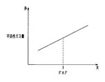
- FIG. 3 is a diagram showing the relationship between the air-fuel ratio correction coefficient and the amount of inert gas.
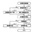
- FIG. 4 is a flowchart showing the control procedure of fuel injection of gaseous fuel
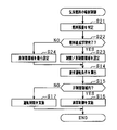
- FIG. 5 is a flowchart showing a control procedure of gaseous fuel injection in the second embodiment.
- compressed natural gas which is a gaseous fuel
- gasoline which is a liquid fuel
- FIG. 1 An overall schematic diagram of the fuel injection system is shown in FIG.
- the intake system 11 is an inline three-cylinder spark ignition engine, and an intake system 11 and an exhaust system 12 are connected to an intake port and an exhaust port, respectively.
- the intake system 11 has an intake manifold 13 and an intake pipe 14.
- the intake manifold 13 includes a plurality of intake branch pipe portions 13a (for the number of cylinders of the engine 10) connected to an intake port of the engine 10 and an intake air collection portion 13b connected to the intake pipe 14 on the upstream side.
- the number of intake branch pipe portions 13a is the number of cylinders of the engine 10.
- the intake pipe 14 is provided with a throttle valve 15 as an air amount adjusting unit.
- the throttle valve 15 is configured as an electronically controlled throttle valve whose opening degree is adjusted by a throttle actuator 15a such as a DC motor.
- the opening degree of the throttle valve 15 is detected by a throttle opening degree sensor 15b built in the throttle actuator 15a.
- the opening degree of the throttle valve 15 is the throttle opening degree.
- an intake valve is provided in the intake port of the engine 10, and an air-fuel mixture is introduced into the cylinder 24 or into the cylinder by opening the intake valve.
- the exhaust system 12 has an exhaust manifold 16 and an exhaust pipe 17.
- the exhaust manifold 16 has a plurality of exhaust branch pipe portions 16 a connected to the exhaust port of the engine 10 and an exhaust collecting portion 16 b connected to the exhaust pipe 17 on the downstream side.
- the number of exhaust branch pipe portions 16a is equal to the number of cylinders of the engine 10.
- the exhaust port of the engine 10 is provided with an exhaust valve. Exhaust gas after combustion of the engine 10 is discharged from the cylinders 24 of the engine 10 to the exhaust pipe 17 by opening the exhaust valve.
- the exhaust pipe 17 is provided with an exhaust sensor for detecting exhaust components and a catalyst 19 for purifying the exhaust. As the exhaust sensor, an air-fuel ratio sensor 18 that detects the air-fuel ratio from the oxygen concentration in the exhaust is provided.
- the engine 10 is provided with a variable valve operating device 26 that variably adjusts the opening / closing timing of an intake valve (not shown).
- a variable valve operating device 26 that variably adjusts the opening / closing timing of an intake valve (not shown).
- the opening timing and closing timing of the intake valve are advanced. It can be changed to the side or retarded side.
- the configuration of the variable valve device 26 is well known and will not be described here. For example, it may be provided with a hydraulically or electrically driven phase adjusting mechanism.
- the engine 10 of this embodiment is an engine with a supercharger, and supercharging of intake air is performed by a turbocharger 31 as a supercharger.
- the turbocharger 31 has an intake air compressor 32 provided in the intake pipe 14 and an exhaust turbine 33 provided in the exhaust pipe 17, and these are connected so as to be integrally rotatable by a rotating shaft (not shown).
- a bypass passage 34 is provided between an upstream portion and a downstream portion of the exhaust pipe 17 with the exhaust turbine 33 interposed therebetween, and an electric waste gate valve 35 is provided in the bypass passage 34.
- a spark plug 20 is provided in each cylinder 24 of the engine 10.
- a high voltage is applied to the ignition plug 20 at a desired ignition timing through an ignition device 20a including an ignition coil. By applying this high voltage, a spark discharge is generated between the opposing electrodes of each spark plug 20, and the fuel introduced into the cylinder 24 (combustion chamber) is ignited and used for combustion.
- the fuel injection system includes a first injection valve 21 that injects gaseous fuel and a second injection valve 22 that injects liquid fuel as a fuel injection unit that injects and supplies fuel to the engine 10.
- the second injection valve 22 corresponds to a liquid fuel injection valve.
- the first injection valve 21 is a port injection type that injects fuel into the intake branch pipe portion 13 a of the intake manifold 13, and the second injection valve 22 is placed in the cylinder 24 of the engine 10. It is a direct injection type that directly injects fuel.
- Each of the injection valves 21 and 22 is an open / close type control valve in which the valve body is lifted from the closed position to the open position by electrically driving the electromagnetic drive unit, and the valve opening drive input from the control unit 80 Each valve is driven to open by a signal.
- Each of these injection valves 21 and 22 is opened by energization, closed by energization interruption, and injects an amount of fuel corresponding to the energization time.
- the fuel includes gaseous fuel and liquid fuel.
- the gaseous fuel supply unit 40 that supplies gaseous fuel to the first injection valve 21 and the liquid fuel supply unit 70 that supplies liquid fuel to the second injection valve 22 will be described.
- a gas tank 42 is connected to the first injection valve 21 via a gas pipe 41.
- a regulator 43 is provided as a pressure adjustment unit that adjusts the pressure of the gaseous fuel supplied to the first injection valve 21 to reduce the pressure.
- the regulator 43 uses a predetermined set pressure (for example, 0.2 to 1.0 MPa), which is a high pressure state (for example, a maximum of 20 MPa) of gaseous fuel stored in the gas tank 42 as an injection pressure of the first injection valve 21.
- the pressure is adjusted so as to be a constant pressure within the range.
- the gaseous fuel after the decompression adjustment is supplied to the first injection valve 21 through the gas pipe 41.
- the gas pipe 41 further includes a tank main stop valve 44 disposed near the fuel outlet of the gas tank 42, and a shut-off valve disposed downstream of the tank main stop valve 44 and near the fuel inlet of the regulator 43. 45 is provided. These valves 44 and 45 allow and block the flow of gaseous fuel in the gas pipe 41. Both the tank main stop valve 44 and the shut-off valve 45 are electromagnetic on-off valves, and are normally closed types in which the flow of gaseous fuel is blocked when not energized and the flow of gaseous fuel is allowed when energized.
- pressure sensors 46a and 46b for detecting the fuel pressure and temperature sensors 47a and 47b for detecting the fuel temperature are provided on the upstream side and the downstream side of the regulator 43, respectively.
- a fuel tank 72 is connected to the second injection valve 22 via a fuel pipe 71.
- the fuel pipe 71 is provided with a fuel pump 73 that feeds the liquid fuel in the fuel tank 72 to the second injection valve 22.
- the fuel injection system is provided with a starter 25 as a starting device that applies initial rotation to the engine 10 when the engine is started.
- the control unit 80 includes a CPU 81, a ROM 82, a RAM 83, a backup RAM (BK RAM) 84, an interface (I / F) 85, and a bidirectional bus 86.
- the CPU 81, ROM 82, RAM 83, backup RAM 84, and interface 85 are connected to each other by a bidirectional bus 86.
- the CPU 81 executes a routine (program) for controlling the operation of each part in the fuel injection system.
- the ROM 82 stores in advance a routine executed by the CPU 81 and various data such as a map and a parameter that are referred to when the routine is executed.
- the map includes a table, a relational expression, and the like.
- the RAM 83 temporarily stores data as necessary when the CPU 81 executes a routine.
- the backup RAM 84 appropriately stores data under the control of the CPU 81 in a state where the power is turned on, and retains the stored data even after the power is shut off.
- the interface 85 is electrically connected to the throttle opening sensor 15b, the air-fuel ratio sensor 18, the pressure sensors 46a and 46b, the temperature sensors 47a and 47b, and other sensors provided in the fuel injection system.
- these sensors include a crank angle sensor, a cam angle sensor, an air flow meter, a cooling water temperature sensor, a vehicle speed sensor, an accelerator sensor, and the like.
- An output corresponding to detection signals from these sensors is transmitted to the CPU 81.
- the interface 85 is electrically connected to driving units such as the throttle actuator 15a, the ignition device 20a, the injection valves 21 and 22, the variable valve device 26, the waste gate valve 35, the tank main stop valve 44, and the shutoff valve 45.
- the drive unit is driven by outputting a drive signal sent from the CPU 81 to the drive unit. That is, the control unit 80 acquires the operating state of the engine 10 based on the output signal of the above-described sensor and controls the above-described driving unit based on the acquired operating state.
- a target air amount of the engine 10 is calculated based on an accelerator operation amount detected by an accelerator sensor, an engine rotation speed detected by a crank angle sensor, and the like, and based on the calculated value, the throttle actuator 15a Control the drive.
- the fuel injection amount is calculated based on the engine rotation speed, the intake air amount detected by the air flow meter, the engine load, and the like, and the driving of the injection valves 21 and 22 is controlled based on the calculated value.
- the fuel injection amount is a required amount.
- the optimal ignition timing is calculated based on the engine rotation speed, the intake air amount, and the like, and the drive of the ignition device 20a is controlled so that ignition is performed at the optimal ignition timing.
- the target valve opening timing or target valve closing timing of the intake valve is calculated based on the engine speed, the intake air amount, and the like, and the drive of the variable valve device 26 is controlled based on the calculated value.
- the control unit 80 has a function of switching between the gas fuel mode and the liquid fuel mode.
- the control unit 80 performs gaseous fuel injection by the first injection valve 21 in the gaseous fuel mode, and performs liquid fuel injection by the second injection valve 22 in the liquid fuel mode. Switching between these modes may be performed according to the remaining amount of fuel in the tank, an input signal from a fuel selection switch (not shown), or the like. Specifically, when the remaining amount of gaseous fuel in the gas tank 42 falls below a predetermined value or when the use of liquid fuel is selected by the fuel selection switch, the control unit 80 uses the second injection valve 22. The engine 10 is combusted by liquid fuel injection.
- control unit 80 controls the gaseous fuel by the first injection valve 21.
- the combustion of the engine 10 is performed by the injection of.
- the amount of fuel required for combustion is larger than that of liquid fuel, so that a desired amount of fuel cannot be injected at a predetermined time in the combustion cycle, for example, in a high-load operation state.
- a desired amount of fuel cannot be injected at a predetermined time in the combustion cycle, for example, in a high-load operation state.
- unintended fuel shortage will lead to deterioration of exhaust emissions. Therefore, for example, in the high load operation state, the injection of the gaseous fuel is limited, thereby preventing an unintended fuel shortage.
- the lean deviation of the air-fuel ratio may occur due to the fact that the desired fuel amount cannot be injected.
- the composition varies greatly. That is, there are areas where the mined natural gas is used as fuel without being refined, and the fuel composition varies greatly depending on the mining area.
- the inert gas such as nitrogen and carbon dioxide
- the injection restriction region is set with a margin in anticipation of an increase in the required fuel amount when a large amount of inert gas (impurities) is contained.
- the injection restriction region is the region A in FIG.
- the criterion for determining whether or not the fuel injection of the required amount by the first injection valve 21 can be performed is set variably based on the fuel composition, and the fuel composition at each time is set. Gaseous fuel restriction can be implemented appropriately while making it compatible.
- the boundary line between the injection restricted area A and the non-restricted area B in FIG. Specifically, as shown in FIG. 2, in the case of gaseous fuel with a large amount of inert gas, the criterion is shifted to a lower speed and a lower load side in order to narrow the region where the required amount of fuel injection can be performed, and vice versa.
- the determination criterion is shifted to a higher speed and a higher load side in order to expand a region where a required amount of fuel injection can be performed.
- the region is an unrestricted region B where the injection of gaseous fuel is not restricted.
- FIG. 4 is a flowchart showing a processing procedure related to injection control of gaseous fuel. This process is repeatedly performed at a predetermined cycle by the CPU 81 of the control unit 80 in the gaseous fuel mode.
- the control unit 80 determines whether or not learning of the gaseous fuel composition is completed.
- the fuel composition learning method may be arbitrary, in the present embodiment, the control unit 80 performs the fuel composition learning based on the fuel correction amount under the gaseous fuel mode. Briefly, the control unit 80 calculates an air-fuel ratio correction coefficient FAF required to make the actual air-fuel ratio coincide with the target air-fuel ratio when performing the air-fuel ratio feedback control, and based on the air-fuel ratio correction coefficient FAF. To calculate the fuel composition.
- the fuel amount to be increased by the correction increases with respect to the basic injection amount calculated based on the engine speed and the engine load, and the air-fuel ratio correction coefficient FAF is Larger value.
- the fuel amount is increased or decreased by correction (whether FAF> 1 or FAF ⁇ 1) is determined according to the reference fuel composition.
- the fuel composition is a reference composition that is a premise of the basic injection amount. If the amount of inert gas mixed in relative to the reference composition is large, the fuel amount is increased by correction (FAF> 1). Conversely, if the amount of inert gas mixed in relative to the reference composition is small, the correction is made. This reduces the amount of fuel (FAF ⁇ 1).
- the control unit 80 calculates the amount of inert gas as a parameter of the fuel composition based on the air-fuel ratio correction coefficient FAF.
- the inert gas amount calculated in this way is sequentially stored in the backup memory as a learning value.
- the learning of the fuel composition may be performed every time the vehicle is operated (once per trip) or every time fuel gas is replenished.
- the control unit 80 proceeds to S12, and sets the injection restriction region A and the non-restriction region B based on the amount of inert gas in the gaseous fuel (result of fuel composition learning).
- S12 corresponds to an area setting unit.
- the control unit 80 expands the injection restriction region A, that is, expands the region in which fuel injection by the first injection valve 21 is restricted, as the amount of the inert gas increases. More specifically, in FIG.
- the setting range in which the criterion is changed is La to Lc, and if the inert gas amount is larger than the predetermined amount K when the criterion is L1, the criterion is If it is shifted from L1 to La and the amount of the inert gas is less than the predetermined amount K, the determination criterion is shifted from L1 to Lc.
- the determination criterion is desirably changed in small increments according to the amount of inert gas. For example, it is appropriately changed according to the amount of inert gas, such as Lb, which is intermediate between L1 to La.
- control unit 80 proceeds to S13 and sets the injection restriction region A and the non-restriction region B so that the non-restriction region B is the narrowest.
- the non-restricted region B is minimized by setting the determination criterion to La.
- S13 corresponds to a minimum setting unit.
- the control unit 80 calculates the required operating condition of the engine 10 from the current vehicle and the operating state of the engine 10. Specifically, the engine operating state to be realized is calculated based on the accelerator operation amount, the transmission gear ratio, the electric load driving amount, and the like. In this case, the engine operating state includes the rotation speed and the load.
- the control unit 80 determines whether or not the requested operation condition calculated in S14 is in the unrestricted region B set in S12 and S13. If the controller 80 is in the non-restricted region B, the control unit 80 proceeds to S16 and performs normal control. At this time, the control unit 80 performs normal control for each of these without limiting the operation of the engine 10 and others. In addition, if the control unit 80 is not in the non-restricted region B (that is, if it is in the injection restricted region A), the control unit 80 proceeds to S17 and performs operation restriction on the engine 10 and others. Note that S15 corresponds to the operating state determination unit, and S17 corresponds to the injection limiting unit.
- the following restrictions are applied to the operation restriction. That is, when the required operating condition is in the injection restriction region A, it is necessary to reduce the fuel injection amount of the gaseous fuel with respect to the original fuel injection amount.
- the intake air amount of the engine 10 The fuel injection amount of the gaseous fuel is reduced by reducing.
- Specific means for reducing the intake air amount include the following (1) to (3). (1) The throttle valve 15 is controlled to reduce the opening. (2) The drive of the variable valve device 26 is controlled so that the closing timing of the intake valve is kept away from the intake bottom dead center. That is, the closing timing of the intake valve is advanced or retarded with respect to the intake bottom dead center. If the variable valve device 26 can change the lift amount of the intake valve, the lift amount is limited. (3) By adjusting the opening degree of the wastegate valve 35 of the turbocharger 31, the supercharging pressure is limited to a lower pressure side.
- the operation restriction is performed as described above, so that the fuel injection amount is suppressed from leaning against the intention, and as a result, the exhaust emission deteriorates. The inconvenience of doing is suppressed.
- the determination criterion for determining whether or not the fuel injection of the required amount by the first injection valve 21 can be performed is set variably based on the fuel composition, it is possible to correspond to the fuel composition at each time. Gaseous fuel restriction can be implemented properly. As a result, it is possible to make an appropriate judgment regarding the implementation of the injection of the gaseous fuel, and to suppress inconveniences such as deterioration of exhaust emission and drivability.
- the non-restricted region B is made narrower than when the amount is small.
- the non-restricted area B is an unrestricted operation area. Accordingly, when the amount of the inert gas is large, the fuel injection can be appropriately performed in consideration of the increase in the volume of the fuel injection.
- the non-restricted region B is set to the narrowest region (for example, a region using La in FIG. 2 as a criterion) among the changeable ranges. Accordingly, it is possible to suppress the deterioration of exhaust emission due to the lean deviation of the air-fuel ratio even when the fuel composition is unlearned while considering that there is a composition variation in the gaseous fuel.
- the fuel injection of the first injection valve 21 is limited by limiting the intake air amount.
- the restriction on the intake air amount and the restriction on the injection of the gaseous fuel it is possible to suppress the air-fuel ratio shift and thus to suppress the deterioration of the exhaust emission.
- the remaining amount of fuel in the gas tank 42 is determined, and the determination criterion is variably set based on the remaining amount of fuel.
- FIG. 5 is a flowchart showing a processing procedure relating to injection control of gaseous fuel in the present embodiment, and this processing is performed in place of FIG. 4 described above. 5 is obtained by changing a part of FIG. 4, and S11 to S13 in FIG. 4 are changed to S21 to S24.
- the control unit 80 determines the remaining amount of fuel in the gas tank 42. This remaining fuel amount is obtained from, for example, the detection value of the pressure sensor 46a provided on the upstream side of the regulator 43, or from the detection value of the tank internal pressure sensor when the gas tank 42 is provided with a tank internal pressure sensor. Good. S21 corresponds to a remaining amount determination unit.
- the control unit 80 determines whether or not fuel composition learning, which is calculation of the amount of inert gas in the gaseous fuel, is completed. This process is the same as S11 in FIG. Then, when S22 is YES, the control unit 80 proceeds to S23, and sets the injection restriction region A and the non-restriction region B based on the amount of inert gas in the gaseous fuel and the remaining amount of fuel.
- the control unit 80 sets the areas A and B based on the remaining amount of fuel in addition to the amount of inert gas. Specifically, the control unit 80 expands the injection restriction area A when the amount of inert gas is large, and narrows the injection restriction area A when the amount of inert gas is small. When it becomes less than Th, the areas A and B are set based on the remaining fuel amount. At this time, when the remaining amount of fuel becomes less than Th, the injection restriction region A may be expanded as the remaining amount decreases.
- the predetermined value Th is preferably determined based on whether or not the pressure adjustment at the set pressure is possible in the regulator 43, and the remaining amount of fuel is reduced to such an extent that the pressure adjustment at the set pressure is impossible. Is a determination value for determining.
- control unit 80 proceeds to S24, and performs the minimum setting of the non-restricted region B while taking into account the remaining amount of fuel. That is, when the remaining amount of fuel is small, it becomes difficult to perform the required amount of fuel injection. Therefore, the non-restricted region B is narrowed as the remaining amount of fuel decreases.
- control unit 80 calculates the required operating condition of the engine 10 and determines whether or not the required operating condition is in the non-restricted region B (S14, S15). Then, the control unit 80 performs normal control if it is in the non-restricted region B, and performs operation restriction on the engine 10 and others if it is not in the non-restricted region B (S16, S17).
- the tank internal pressure decreases, and it becomes difficult for the regulator 43 to adjust the fuel pressure to a predetermined pressure (that is, the fuel pressure becomes equal to or lower than the predetermined pressure).
- the regulator 43 since the fuel injection rate decreases as the remaining fuel amount decreases, the determination of whether or not the required amount of fuel injection by the first injection valve 21 can be performed is also affected, and the determination is made appropriately. Otherwise, the remaining gaseous fuel cannot be used properly. For example, there is a possibility that the determination that the vehicle cannot be traveled is made prematurely.
- the determination criterion is set based on the fuel remaining amount in addition to the fuel composition, it is prematurely determined that the remaining gas fuel is properly used and the vehicle cannot be driven. Can be suppressed.
- the fuel in the gas tank 42 can be properly used until the remaining amount becomes small, which can contribute to the extension of the travel distance of the vehicle.
- the following processing is performed instead of reducing the intake air amount of the engine 10 as described above. It may be. That is, in the case where the injection restriction of the gaseous fuel is performed, dual injection in which the liquid fuel is injected by the second injection valve 22 in addition to the injection of the gaseous fuel by the first injection valve 21 may be used. Specifically, in S17 of FIGS. 4 and 5, the required amount as the fuel injection amount is injected by the first injection valve 21 by the amount that can be injected by the first injection valve 21, and the remaining shortage is second. Injection is performed by the injection valve 22.
- the switching control may be performed in which the liquid fuel is injected by the second injection valve 22 instead of the gaseous fuel injection by the first injection valve 21. Specifically, in S17 of FIGS. 4 and 5, the fuel injection of the first injection valve 21 is stopped, and all the required amount as the fuel injection amount is injected by the second injection valve 22.
- the present disclosure has been embodied in a bi-fuel engine that uses gaseous fuel (CNG) and liquid fuel (gasoline) as fuel for combustion.
- CNG gaseous fuel
- gasoline liquid fuel
- this is changed to a gas engine that uses only gaseous fuel. It is also possible to embody the present disclosure.
- the CNG fuel is used as the gaseous fuel.
- gaseous fuel that is gas in the standard state can be used.
- a fuel mainly composed of methane, ethane, propane, butane, hydrogen, or the like is used. May be.
- the liquid fuel is not limited to gasoline fuel, and for example, light oil may be used.
Landscapes
- Engineering & Computer Science (AREA)
- Chemical & Material Sciences (AREA)
- Combustion & Propulsion (AREA)
- Mechanical Engineering (AREA)
- General Engineering & Computer Science (AREA)
- Output Control And Ontrol Of Special Type Engine (AREA)
- Electrical Control Of Air Or Fuel Supplied To Internal-Combustion Engine (AREA)
Abstract
エンジン(10)では、第1噴射弁(21)から気体燃料が噴射される。制御部(80)は、エンジン運転状態に基づいて第1噴射弁21による燃料噴射の要求量を設定し、該要求量に基づいて第1噴射弁(21)の燃料噴射を実施する。また、制御部(80)は、現時点のエンジン運転状態について、第1噴射弁(21)による要求量の燃料噴射が実施できる状態であるか否かを判定し、第1噴射弁(21)による要求量の燃料噴射が実施できる状態でないと判定した場合に、第1噴射弁(21)による燃料噴射の制限を実施する。またその一方で、第1噴射弁(21)に供給される気体燃料の組成を判定し、その燃料組成に基づいて、要求量の燃料噴射の実施の可否を判定する判定基準を可変に設定する。
Description
本開示は、2014年1月8日に出願された日本出願番号2014-1601号に基づくもので、ここにその記載内容を援用する。
本開示は、内燃機関の制御装置に関するものである。
天然ガス(CNG)等の気体燃料を用いる場合には、液体燃料を用いる場合に比べて燃焼に要する燃料量が異なり、その燃料量の差異を考慮した技術が各種記載されている。例えば、特許文献1に記載の技術では、液体燃料の噴射量に基づいて気体燃料の噴射量を算出するシステムにおいて、気体燃料の組成変化に応じて気体燃料の噴射量を補正する。そしてこれにより、気体燃料の組成が変化した場合でも安定した気体燃料噴射を実現でき、エミッション性能の低下や空燃比センサの故障誤検知を防止することが可能である。
しかしながら、天然ガス(CNG)等の気体燃料を用いる場合には、燃料組成が大きくばらつく。その燃料組成のばらつきに起因して、燃焼ごとに要する燃料量のばらつきが生じる。この場合、気体燃料中の不活性ガス成分(不純物)が多くなると、燃焼ごとに要する燃料量が多くなり、さらに短時間に大量の燃料を噴射しなければならない高回転と高負荷運転時においては、空燃比が意図せずリーンになる。したがって、排気エミッションの悪化やドライバビリティの低下等の不都合が生じるおそれがある。
本開示は、気体燃料の噴射の実施に関して適正な判断を行わせ、ひいては排気エミッションの悪化やドライバビリティの低下等の不都合を抑制することができる内燃機関の制御装置を提供することを目的とするものである。
本開示の第一の態様において、内燃機関の制御装置は、燃料タンクから供給される気体燃料の圧力を所定圧力に調整する圧力調整部と、内燃機関において前記圧力調整部による圧力調整後の気体燃料を噴射する気体燃料噴射弁とを備える燃料噴射システムに適用され、前記内燃機関の運転状態に基づいて前記気体燃料噴射弁による燃料噴射の要求量を設定するとともに、該要求量に基づいて前記気体燃料噴射弁の燃料噴射を実施するものである。そして、都度の前記内燃機関の運転状態について、前記気体燃料噴射弁による前記要求量の燃料噴射が実施できる状態であるか否かを判定する運転状態判定部と、前記運転状態判定部が、前記気体燃料噴射弁による前記要求量の燃料噴射が実施できる状態でないと判定した場合に、前記気体燃料噴射弁による燃料噴射の制限を実施する噴射制限部と、前記気体燃料噴射弁に供給される気体燃料の組成を判定する組成判定部と、前記組成判定部により判定した燃料組成に基づいて、前記運転状態判定部において前記要求量の燃料噴射の実施の可否を判定する判定基準を可変に設定する設定部と、を備える。
天然ガス等で構成される気体燃料を使用する場合、液体燃料に比べて燃焼に要する燃料体積量が大きくなるため、例えば高負荷運転状態において燃焼サイクル内の所定時期に所望の量の燃料を噴射しきれないと、意図しない燃料不足により排気エミッションの悪化等を招くことになる。そのため、例えば高負荷運転状態にあっては燃料噴射を制限し、これにより意図しない燃料不足が生じない。
一方で、気体燃料の場合は組成が大きくばらつくことが想定され、不活性成分(不純物)を多く含んでいる場合に必要燃料量が多くなることを見越して、余裕をもって噴射制限領域を設定しておく。しかしながら、実際に不活性成分(不純物)の少ない気体燃料を使用している場合には、噴射制限が不要に実施される。かかる場合には、過剰な噴射制限(本来不要な制限)が実施されることで、ドライバビリティの低下等の不都合を発生するおそれがある。
この点、上記構成では、気体燃料噴射弁による要求量の燃料噴射が実施できる状態であるか否かを判定するための判定基準を、燃料組成に基づいて可変に設定するようにしたため、都度の燃料組成に対応させつつ気体燃料の制限を適正に実施できる。例えば、不活性成分の少ない気体燃料の場合は気体燃料の噴射を制限無しで実施可能な領域を拡げ、逆に不活性成分の多い気体燃料の場合は気体燃料の噴射を制限無しで実施可能な領域を狭めることが可能となる。その結果、気体燃料の噴射の実施に関して適正な判断を行わせ、ひいては排気エミッションの悪化やドライバビリティの低下等の不都合を抑制することができる。
本開示についての上記目的およびその他の目的、特徴や利点は、添付の図面を参照しながら下記の詳細な記述により、より明確になる。その図面は、
図1は、エンジン制御システムの全体構成を示す概略図であり、
図2は、噴射制限領域と非制限領域とを示す図であり、
図3は、空燃比補正係数と不活性ガス量との関係を示す図であり、
図4は、気体燃料の燃料噴射の制御手順を示すフローチャートであり、
図5は、第2実施形態において気体燃料の燃料噴射の制御手順を示すフローチャートである。
(第1実施形態)
以下、本開示を具体化した実施形態について図面を参照しつつ説明する。本実施形態は、気体燃料である圧縮天然ガス(CNG)と液体燃料であるガソリンとをエンジン燃焼用の燃料として使用し、バイフューエルタイプの車載多気筒エンジンの燃料噴射システムとして具体化している。燃料噴射システムの全体概略図を図1に示す。
以下、本開示を具体化した実施形態について図面を参照しつつ説明する。本実施形態は、気体燃料である圧縮天然ガス(CNG)と液体燃料であるガソリンとをエンジン燃焼用の燃料として使用し、バイフューエルタイプの車載多気筒エンジンの燃料噴射システムとして具体化している。燃料噴射システムの全体概略図を図1に示す。
図1に示すエンジン10は直列3気筒の火花点火式エンジンよりなり、その吸気ポート及び排気ポートには吸気系統11、排気系統12がそれぞれ接続されている。吸気系統11は、吸気マニホールド13と吸気管14とを有している。吸気マニホールド13は、エンジン10の吸気ポートに接続される複数(エンジン10の気筒数分)の吸気分岐管部13aと、その上流側であって吸気管14に接続される吸気集合部13bとを有している。この場合、吸気分岐管部13aの数はエンジン10の気筒数分である。吸気管14には、空気量調整部としてのスロットル弁15が設けられている。このスロットル弁15は、DCモータ等のスロットルアクチュエータ15aにより開度調節される電子制御式のスロットル弁として構成されている。スロットル弁15の開度は、スロットルアクチュエータ15aに内蔵されたスロットル開度センサ15bにより検出される。この場合、スロットル弁15の開度はスロットル開度である。また、エンジン10の吸気ポートには吸気弁が設けられており、吸気弁の開動作により空気と燃料との混合気が気筒24内またはシリンダ内に導入される。
排気系統12は、排気マニホールド16と排気管17とを有している。排気マニホールド16は、エンジン10の排気ポートに接続される複数の排気分岐管部16aと、その下流側であって排気管17に接続される排気集合部16bとを有している。この場合、排気分岐管部16aの数はエンジン10の気筒数分である。エンジン10の排気ポートには排気弁が設けられており、排気弁の開動作によりエンジン10の燃焼後の排気がエンジン10の各気筒24内から排気管17に排出される。排気管17には、排気の成分を検出する排気センサと、排気を浄化する触媒19とが設けられている。排気センサとしては、排気中の酸素濃度から空燃比を検出する空燃比センサ18が設けられている。
エンジン10には、図示しない吸気弁の開閉時期を可変に調整する可変動弁装置26が設けられており、この可変動弁装置26により、吸気弁の開弁時期及び閉弁時期がそれぞれ進角側又は遅角側に変更できる。可変動弁装置26の構成については周知であるためその説明は割愛するが、例えば油圧駆動式又は電気駆動式の位相調機構を備えるものであるとよい。
また、本実施形態のエンジン10は過給機付きエンジンであり、過給機としてのターボチャージャ31により吸気の過給が行われる。ターボチャージャ31は、吸気管14に設けられた吸気コンプレッサ32と、排気管17に設けられた排気タービン33とを有しており、それらが図示しない回転軸により一体回転可能に連結されている。排気タービン33を挟んで排気管17の上流部と下流部との間にはバイパス通路34が設けられており、このバイパス通路34には電動式のウエストゲートバルブ35が設けられている。
エンジン10の各気筒24には点火プラグ20が設けられている。点火プラグ20には、点火コイル等よりなる点火装置20aを通じて、所望とする点火時期に高電圧が印加される。この高電圧の印加により、各点火プラグ20の対向電極間に火花放電が発生し、気筒24内(燃焼室内)に導入された燃料が着火され燃焼に供される。
また、燃料噴射システムは、エンジン10に対して燃料を噴射供給する燃料噴射部として、気体燃料を噴射する第1噴射弁21と、液体燃料を噴射する第2噴射弁22とを有している。本実施形態では、第2噴射弁22は液体燃料噴射弁に相当する。これら噴射弁21,22のうち、第1噴射弁21は、吸気マニホールド13の吸気分岐管部13aに燃料を噴射するポート噴射式であり、第2噴射弁22は、エンジン10の気筒24内に燃料を直接噴射する直噴式となっている。各噴射弁21,22は、電磁駆動部が電気的に駆動されることで弁体が閉位置から開位置にリフトされる開閉タイプの制御弁であり、制御部80から入力される開弁駆動信号によりそれぞれ開弁駆動される。これら各噴射弁21,22は、通電により開弁し、通電遮断により閉弁するとともに、通電時間に応じた量の燃料を噴射する。この場合、燃料は気体燃料と液体燃料含む。
ここで、第1噴射弁21に対して気体燃料を供給する気体燃料供給部40と、第2噴射弁22に対して液体燃料を供給する液体燃料供給部70とについて説明する。気体燃料供給部40において、第1噴射弁21にはガス配管41を介してガスタンク42が接続されている。ガス配管41の途中には、第1噴射弁21に供給される気体燃料の圧力を減圧調整する圧力調整部としてのレギュレータ43が設けられている。具体的に、レギュレータ43は、ガスタンク42内に貯蔵された高圧状態(例えば最大20MPa)の気体燃料が、第1噴射弁21の噴射圧である所定の設定圧(例えば0.2~1.0MPaの範囲内の一定圧)になるように減圧調整するものである。減圧調整後の気体燃料は、ガス配管41を通って第1噴射弁21に供給される。
ガス配管41には更に、ガスタンク42の燃料出口の付近に配置されたタンク主止弁44と、タンク主止弁44よりも下流側であってレギュレータ43の燃料入口の付近に配置された遮断弁45とが設けられている。これら各弁44,45によって、ガス配管41における気体燃料の流通が許容及び遮断される。タンク主止弁44及び遮断弁45はいずれも電磁式の開閉弁であり、非通電時において気体燃料の流通が遮断され、通電時において気体燃料の流通が許容される常閉式である。また、ガス配管41において、レギュレータ43の上流側及び下流側にはそれぞれ、燃料圧力を検出する圧力センサ46a,46bと、燃料温度を検出する温度センサ47a,47bとが設けられている。
液体燃料供給部70において、第2噴射弁22には、燃料配管71を介して燃料タンク72が接続されている。また、燃料配管71には、燃料タンク72内の液体燃料を第2噴射弁22に給送する燃料ポンプ73が設けられている。
その他、燃料噴射システムには、エンジン始動時にエンジン10に初期回転を付与する始動装置としてのスタータ25が設けられている。
制御部80は、CPU81と、ROM82と、RAM83と、バックアップRAM(BK RAM)84と、インターフェース(I/F)85と、双方向バス86とを備えている。CPU81、ROM82、RAM83、バックアップRAM84及びインターフェース85は、双方向バス86によって互いに接続されている。
CPU81は、燃料噴射システムにおける各部の動作を制御するためのルーチン(プログラム)を実行する。ROM82には、CPU81が実行するルーチン、及びこのルーチン実行の際に参照されるマップ、パラメータ等の各種データが予め格納されている。この場合、マップはテーブルや関係式等も含む。RAM83は、CPU81がルーチンを実行する際に、必要に応じてデータを一時的に格納する。バックアップRAM84は、電源が投入された状態でCPU81の制御下でデータを適宜格納するとともに、この格納されたデータを電源遮断後も保持する。
インターフェース85は、上述したスロットル開度センサ15b、空燃比センサ18、圧力センサ46a,46b、温度センサ47a,47bや、燃料噴射システムに設けられたその他のセンサと電気的に接続されている。この場合、これらのセンサにはクランク角センサ、カム角センサ、エアフロメータ、冷却水温センサ、車速センサ、アクセルセンサ等も含む。これらのセンサからの検出信号に相当する出力をCPU81に伝達する。また、インターフェース85は、スロットルアクチュエータ15a、点火装置20a、各噴射弁21,22、可変動弁装置26、ウエストゲートバルブ35、タンク主止弁44、遮断弁45等の駆動部と電気的に接続されており、CPU81から送出された駆動信号を駆動部に向けて出力することによりこれら駆動部を駆動させる。すなわち、制御部80は、上述のセンサの出力信号等に基づいてエンジン10の運転状態を取得し、その取得した運転状態に基づいて上述の駆動部を制御する。
具体的には、例えばアクセルセンサにより検出されるアクセル操作量及びクランク角センサにより検出されるエンジン回転速度等に基づいてエンジン10の目標空気量を算出し、その算出値に基づいてスロットルアクチュエータ15aの駆動を制御する。また、上記エンジン回転速度及びエアフロメータにより検出される吸入空気量またはエンジン負荷等に基づいて燃料噴射量を算出し、その算出値に基づいて各噴射弁21,22の駆動を制御する。この場合、燃料噴射量は要求量である。また、エンジン回転速度及び吸入空気量等に基づいて最適点火時期を算出し、その最適点火時期で点火が行われるように点火装置20aの駆動を制御する。さらに、エンジン回転速度及び吸入空気量等に基づいて吸気弁の目標開弁時期又は目標閉弁時期を算出し、その算出値に基づいて可変動弁装置26の駆動を制御する。
制御部80は、気体燃料モードと液体燃料モードとの切替を実施する機能を有する。制御部80は、気体燃料モードでは、第1噴射弁21による気体燃料の噴射を実施し、液体燃料モードでは、第2噴射弁22による液体燃料の噴射を実施する。これら各モードの切替は、タンク内の燃料残量や、図示しない燃料選択スイッチからの入力信号等に応じて実施されるとよい。具体的には、ガスタンク42内の気体燃料の残存量が所定値を下回った場合又は燃料選択スイッチにより液体燃料の使用が選択されている場合には、制御部80は、第2噴射弁22による液体燃料の噴射によりエンジン10の燃焼を実施する。また、燃料タンク72内の液体燃料の残存量が所定値を下回った場合又は燃料選択スイッチにより気体燃料の使用が選択されている場合には、制御部80は、第1噴射弁21による気体燃料の噴射によりエンジン10の燃焼を実施する。
ところで、CNG等の気体燃料を使用する場合、液体燃料に比べて燃焼に要する燃料体積量が大きいため、例えば高負荷運転状態において燃焼サイクル内の所定時期に所望の量の燃料を噴射しきれないと、意図しない燃料不足により排気エミッションの悪化等を招くことになる。そのため、例えば高負荷運転状態にあっては気体燃料の噴射を制限し、これにより意図しない燃料不足が生じない。例えば、図2において高回転かつ高負荷となる領域Aでは、所望の燃料量を噴射しきれないことに起因して、空燃比のリーンずれが生じるおそれがある。
一方で、CNGの場合は組成が大きくばらつくことが想定される。すなわち、採掘した天然ガスを精製することなく燃料としてそのまま使用する地域もあり、採掘地域によってその燃料組成が大きくばらつく。特に燃料中に窒素や二酸化炭素などの不活性ガスが多く混入している場合、同一空気量あたりに噴射しなければならない燃料体積量が増加する。地域によっては不活性ガスが全体の20%以上を占めている場合もあり、不活性ガス割合に比例して要求噴射量が多くなる。そのため、不活性ガス(不純物)を多く含んでいる場合に要求燃料量が多くなることを見越して、余裕をもって噴射制限領域を設定しておく。本実施形態では、噴射制限領域は図2の領域Aである。しかしながら、実際には不活性ガスの少ない気体燃料を使用している場合に、無駄に噴射制限が生じることがある。かかる場合には、過剰な噴射制限(本来不要な制限)が実施されてしまい、ドライバビリティの低下等の不都合を発生するおそれがある。
そこで本実施形態では、第1噴射弁21による要求量の燃料噴射が実施できる状態であるか否かを判定するための判定基準を、燃料組成に基づいて可変に設定し、都度の燃料組成に対応させつつ気体燃料の制限を適正に実施できる。この場合、図2において噴射制限領域Aと非制限領域Bとの境界線は判定基準である。具体的には、図2に示すように、不活性ガスの多い気体燃料の場合は、要求量の燃料噴射が実施できる領域を狭めるべく判定基準をより低回転と低負荷側にシフトさせ、逆に不活性ガスの少ない気体燃料の場合は、要求量の燃料噴射が実施できる領域を拡げるべく判定基準をより高回転と高負荷側にシフトさせる。この場合、領域は気体燃料の噴射が制限されない非制限領域Bである。
図4は、気体燃料の噴射制御に関する処理手順を示すフローチャートである。本処理は、気体燃料モードである場合に、制御部80のCPU81により所定周期で繰り返し実施される。
図4において、S11では、制御部80は、気体燃料組成の学習が完了しているか否かを判定する。燃料組成学習の手法は任意でよいが、本実施形態では、制御部80は、気体燃料モード下での燃料補正量に基づいて燃料組成の学習を実施する。簡単に説明すると、制御部80は、空燃比フィードバック制御を実施する場合において、実空燃比を目標空燃比に一致させるために要する空燃比補正係数FAFを算出し、その空燃比補正係数FAFに基づいて燃料組成の算出を実施する。この場合、気体燃料において不活性ガスの混入量が多いほど、エンジン回転速度やエンジン負荷に基づき算出される基本噴射量に対して、補正により増加させる燃料量が多くなり、空燃比補正係数FAFは大きい値となる。なお、補正により燃料量を増加させるか減少させるか(FAF>1であるかFAF<1であるか)は、基準とする燃料組成に応じて決まる。この場合、燃料組成は基本噴射量の前提となる基準組成である。その基準組成に対して不活性ガスの混入量が多いと、補正により燃料量を増加させること(FAF>1)になり、逆に基準組成に対して不活性ガスの混入量が少ないと、補正により燃料量を減少させること(FAF<1)になる。
本実施形態では、例えば図3の関係を用い、制御部80は、空燃比補正係数FAFに基づいて燃料組成のパラメータとしての不活性ガス量を算出する。こうして算出した不活性ガス量は、学習値としてバックアップ用のメモリに逐次記憶される。例えば、燃料組成の学習は、車両の運転が行われる都度(1トリップに一回)実施されるか、又は気体燃料の補給の都度実施されるとよい。
制御部80は、S11がYESの場合、S12に進み、気体燃料中の不活性ガス量(燃料組成学習の結果)に基づいて噴射制限領域A及び非制限領域Bの設定を実施する。S12が領域設定部に相当する。この場合、制御部80は、不活性ガス量が多いほど、噴射制限領域Aを拡げる、すなわち第1噴射弁21による燃料噴射を制限する領域を拡げる。より具体的には、図2では、判定基準が変更される設定範囲をLa~Lcとしており、不活性ガス量が、判定基準をL1とする場合の所定量Kよりも多ければ、判定基準がL1からLa側にシフトされ、不活性ガス量が所定量Kよりも少なければ、判定基準がL1からLc側にシフトされる。なお、判定基準は、不活性ガス量に応じて小刻みに変更されるのが望ましく、例えば不活性ガス量に応じてL1~Laの中間であるLb等に適宜変更される。
制御部80は、S11がNOの場合、S13に進み、非制限領域Bが最も狭くなるように噴射制限領域A及び非制限領域Bの設定を実施する。この場合、判定基準をLaとすることで、非制限領域Bを最小とする。S13が最小設定部に相当する。
S14では、制御部80は、今現在の車両及びエンジン10の運転状況から、エンジン10の要求運転条件を算出する。具体的には、アクセル操作量、トランスミッションの変速比、電気負荷の駆動量等に基づいて、実現すべきエンジン運転状態を算出する。この場合、エンジン運転状態は回転速度と負荷を含む。
S15では、制御部80は、S14で算出した要求運転条件が、S12,S13で設定した非制限領域Bに入っているか否かを判定する。そして、制御部80は、非制限領域Bに入っていれば、S16に進んで通常制御を実施する。このとき、制御部80は、エンジン10やその他について運転制限を実施することなく、これら各々について通常制御を実施する。また、制御部80は、非制限領域Bに入っていなければ(すなわち噴射制限領域Aに入っていれば)、S17に進んでエンジン10やその他について運転制限を実施する。なお、S15が運転状態判定部に相当し、S17が噴射制限部に相当する。
運転制限について具体的には、以下の各構成とする。すなわち、要求運転条件が噴射制限領域Aに入っている場合には、気体燃料の燃料噴射量を本来の燃料噴射量に対して減少させる必要があり、本実施形態では、エンジン10の吸入空気量を減少させることで気体燃料の燃料噴射量を減少させる。また、吸入空気量を減少させる手段として具体的には、次の(1)~(3)がある。
(1)スロットル弁15の開度を減じ側に制御する。
(2)吸気弁の閉弁時期を吸気下死点から遠ざけるよう可変動弁装置26の駆動を制御する。つまり、吸気弁の閉弁時期を吸気下死点に対して進角させる、又は遅角させる。なお、可変動弁装置26が吸気弁のリフト量を変更できるものであれば、そのリフト量の制限を実施する。
(3)ターボチャージャ31のウエストゲートバルブ35の開度を調整することで、過給圧をより低圧側に制限する。
(1)スロットル弁15の開度を減じ側に制御する。
(2)吸気弁の閉弁時期を吸気下死点から遠ざけるよう可変動弁装置26の駆動を制御する。つまり、吸気弁の閉弁時期を吸気下死点に対して進角させる、又は遅角させる。なお、可変動弁装置26が吸気弁のリフト量を変更できるものであれば、そのリフト量の制限を実施する。
(3)ターボチャージャ31のウエストゲートバルブ35の開度を調整することで、過給圧をより低圧側に制限する。
要求運転条件が噴射制限領域Aに入っている場合において、上記のとおり運転制限が実施されることで、燃料噴射量が意に反してリーンとなることが抑制され、その結果として排気エミッションが悪化するという不都合が抑制される。
以上詳述した本実施形態によれば、以下の優れた効果が得られる。
第1噴射弁21による要求量の燃料噴射が実施できる状態であるか否かを判定するための判定基準を、燃料組成に基づいて可変に設定するようにしたため、都度の燃料組成に対応させつつ気体燃料の制限を適正に実施できる。これにより、気体燃料の噴射の実施に関して適正な判断を行わせ、ひいては排気エミッションの悪化やドライバビリティの低下等の不都合を抑制することができる。
気体燃料中の不活性ガス量が多い場合に、少ない場合に比べて非制限領域Bを狭めるようにした。この場合、非制限領域Bは制限無し運転領域である。これにより、不活性ガス量が多い場合には燃料噴射の体積が増えることを加味して、燃料噴射を適正に実施できる。
気体燃料の組成学習が完了する以前は、非制限領域Bを、変更可能な範囲のうちで最も狭い領域(例えば図2のLaを判定基準とする領域)で設定するようにした。これにより、気体燃料に組成のばらつきが存在することを考慮しつつ、燃料組成が未学習の状態でも空燃比のリーンずれに起因する排気エミッションの悪化を抑制できる。
第1噴射弁21による要求量の燃料噴射が実施できないと判定される場合には、吸入空気量の制限を行うことで第1噴射弁21の燃料噴射の制限を実施する。この場合、吸入空気量の制限と気体燃料の噴射制限とを併せて実施することによって、空燃比ずれを抑制し、ひいては排気エミッションの悪化を抑制できる。
(第2実施形態)
本実施形態では、上記第1実施形態との相違点として、ガスタンク42内の燃料残量を判定し、その燃料残量に基づいて判定基準の可変設定を実施する。
本実施形態では、上記第1実施形態との相違点として、ガスタンク42内の燃料残量を判定し、その燃料残量に基づいて判定基準の可変設定を実施する。
図5は、本実施形態における気体燃料の噴射制御に関する処理手順を示すフローチャートであり、本処理は、上述の図4に置き換えて実施される。なお、図5は、図4の一部を変更したものであり、図4のS11~S13を、S21~S24に変更している。
図5において、S21では、制御部80は、ガスタンク42内の燃料残量の判定を実施する。この燃料残量は、例えばレギュレータ43の上流側に設けられた圧力センサ46aの検出値から求められる他、ガスタンク42にタンク内圧センサが設けられている場合にそのタンク内圧センサの検出値から求められるとよい。S21が残量判定部に相当する。
S22では、制御部80は、気体燃料中の不活性ガス量の算出である燃料組成学習が完了しているか否かを判定する。この処理は図4のS11と同じ処理である。そして、制御部80は、S22がYESの場合、S23に進み、気体燃料中の不活性ガス量と燃料残量とに基づいて噴射制限領域A及び非制限領域Bの設定を実施する。
この場合、制御部80は、図2に示す噴射制限領域A及び非制限領域Bを設定する際において、不活性ガス量に加えて燃料残量に基づいて各領域A,Bを設定する。具体的には、制御部80は、不活性ガス量が多い場合に噴射制限領域Aを拡げ、不活性ガス量が少ない場合に噴射制限領域Aを狭めることに加えて、燃料残量が所定値Thよりも少なくなった場合に、その燃料残量に基づいて各領域A,Bを設定する。このとき、燃料残量が残り少なくなってTh未満となった場合に、その残量が少ないほど、噴射制限領域Aを拡げるとよい。所定値Thは、レギュレータ43において設定圧での圧力調整が可能か否かを基準として定められているとよく、その設定圧での圧力調整が不可となる程度まで燃料残量が減っていることを判定するための判定値である。
また、制御部80は、S22がNOの場合、S24に進み、燃料残量を加味しつつ、非制限領域Bの最小設定を実施する。つまり、燃料残量が少ない場合には、要求量の燃料噴射を実施することが厳しくなることから、燃料残量が少なくなるほど非制限領域Bをより狭める。
S14以降は、図4で説明したとおりである。略述すると、制御部80は、エンジン10の要求運転条件を算出し、その要求運転条件が非制限領域Bに入っているか否かを判定する(S14,S15)。そして、制御部80は、非制限領域Bに入っていれば通常制御を実施し、非制限領域Bに入っていなければエンジン10やその他について運転制限を実施する(S16,S17)。
要するに、ガスタンク42内の燃料残量の低下が生じると、タンク内圧が低下し、レギュレータ43において燃圧を所定圧力に調整することが困難になる(すなわち燃圧が所定圧力以下になる)。この場合、燃料残量の低下に伴い燃料の噴射率が低下することから、第1噴射弁21による要求量の燃料噴射が実施できるかどうかの判断にも影響が及び、その判断が適正に行われないと、残り少なくなった気体燃料を適正に使用できなくなる。例えば、車両走行ができなくなるとの判断が時期尚早に行われるおそれがある。
この点、燃料組成に加えて、燃料残量に基づいて判定基準の設定を行うため、残り少なくなった気体燃料を適正に使用し、車両走行ができなくなるとの判断が時期尚早に行われるといった不都合を抑制できる。また、ガスタンク42内の燃料を残り僅かになるまで適正に使用することができるようになり、車両の走行距離の延長化にも寄与できる。
(他の実施形態)
上記実施形態を例えば次のように変更してもよい。
上記実施形態を例えば次のように変更してもよい。
要求運転条件が噴射制限領域Aに入っており、気体燃料の噴射制限を実施する場合に、既述のようにエンジン10の吸入空気量を減少させることに代えて、以下の処理を実施するようにしてもよい。すなわち、気体燃料の噴射制限が実施される場合に、第1噴射弁21による気体燃料の噴射に加えて、第2噴射弁22による液体燃料の噴射を実施するデュアル噴射にしてもよい。具体的には、図4,図5のS17において、燃料噴射量としての要求量のうち第1噴射弁21で噴射可能な分だけ第1噴射弁21で噴射し、残りの不足分を第2噴射弁22で噴射する。
本構成においても、空燃比ずれに伴う排気エミッションの悪化を抑制できるとともに、さらにドライバビリティの低下を抑制できる。また、気体燃料使用を継続しつつ不足分に応じて液体燃料を使用することで、できる限り気体燃料を用いての運転を継続することができる。
又は、気体燃料の噴射制限が実施される場合に、第1噴射弁21による気体燃料の噴射に代えて、第2噴射弁22による液体燃料の噴射を実施する切替制御にしてもよい。具体的には、図4,図5のS17において、第1噴射弁21の燃料噴射を停止させ、燃料噴射量としての要求量を全て第2噴射弁22で噴射する。
本構成においても、空燃比ずれに伴う排気エミッションの悪化を抑制できるとともに、さらにドライバビリティの低下を抑制できる。また、自動的に液体燃料に切り替えることで、不活性ガス量の多い気体燃料を用いる場合であっても車両の走行性能を損なうことを抑制できる。
上記実施形態では、気体燃料(CNG)と液体燃料(ガソリン)とを燃焼用の燃料として使用するバイフューエルエンジンにて本開示を具体化したが、これを変更し、気体燃料のみを用いるガスエンジンにて本開示を具体化することも可能である。
上記実施形態では、気体燃料としてCNG燃料を用いたが、標準状態で気体となるその他の気体燃料を用いることもでき、例えばメタン、エタン、プロパン、ブタン、水素などを主成分とする燃料を用いてもよい。また、液体燃料についてもガソリン燃料に限らず、例えば軽油などを用いてもよい。
本開示は、実施例に準拠して記述されたが、本開示は当該実施例や構造に限定されるものではないと理解される。本開示は、様々な変形例や均等範囲内の変形をも包含する。加えて、様々な組み合わせや形態、さらには、それらに一要素のみ、それ以上、あるいはそれ以下、を含む他の組み合わせや形態をも、本開示の範疇や思想範囲に入るものである。
Claims (6)
- 燃料タンク(42)から供給される気体燃料の圧力を所定圧力に調整する圧力調整部(43)と、内燃機関(10)において前記圧力調整部による圧力調整後の気体燃料を噴射する気体燃料噴射弁(21)とを備える燃料噴射システムに適用され、前記内燃機関の運転状態に基づいて前記気体燃料噴射弁による燃料噴射の要求量を設定するとともに、該要求量に基づいて前記気体燃料噴射弁の燃料噴射を実施する内燃機関の制御装置であって、
都度の前記内燃機関の運転状態について、前記気体燃料噴射弁による前記要求量の燃料噴射が実施できる状態であるか否かを判定する運転状態判定部(80、S15)と、
前記運転状態判定部が、前記気体燃料噴射弁による前記要求量の燃料噴射が実施できる状態でないと判定した場合に、前記気体燃料噴射弁による燃料噴射の制限を実施する噴射制限部(80、S17)と、
前記気体燃料噴射弁に供給される気体燃料の組成を判定する組成判定部(80、S11)と、
前記組成判定部により判定した燃料組成に基づいて、前記運転状態判定部において前記要求量の燃料噴射の実施の可否を判定する判定基準を可変に設定する領域設定部(80、S12)と、を備える内燃機関の制御装置。 - 前記組成判定部は、前記気体燃料の組成判定として当該気体燃料に含まれる不活性ガス量を算出するものであり、
前記設定部は、前記不活性ガス量が多い場合に、少ない場合に比べて、前記気体燃料噴射弁による前記要求量の燃料噴射が実施できるとする制限無し運転領域を狭めるようにして前記判定基準を設定する請求項1に記載の内燃機関の制御装置。 - 前記運転状態判定部は、前記気体燃料噴射弁による前記要求量の燃料噴射が実施できるとする制限無し運転領域を定めておき、前記内燃機関の運転状態が前記制限無し運転領域に入っているか否かに基づいて、前記気体燃料噴射弁による前記要求量の燃料噴射が実施できる状態か否かを判定するものであり、
前記組成判定部による気体燃料の組成判定が完了する以前は、前記制限無し運転領域を、前記組成判定が完了した状態での設定範囲のうち最も狭い領域で設定する最小設定部(80、S13)を備える請求項1又は2に記載の内燃機関の制御装置。 - 前記燃料タンク内の燃料残量を判定する残量判定部(80、S21)を備え、
前記設定部は、前記残量判定部により判定した燃料残量に基づいて、前記判定基準を可変に設定する請求項1乃至3のいずれか1項に記載の内燃機関の制御装置。 - 前記噴射制限部は、前記運転状態判定部が、前記気体燃料噴射弁による前記要求量の燃料噴射が実施できる状態でないと判定した場合に、前記内燃機関に吸入される空気量を制限することで前記気体燃料噴射弁による燃料噴射の制限を実施するものである請求項1乃至4のいずれか1項に記載の内燃機関の制御装置。
- 液体燃料を噴射する液体燃料噴射弁(22)を備える燃料噴射システムに適用され、
前記噴射制限部により前記気体燃料噴射弁による燃料噴射の制限が実施される場合に、当該気体燃料噴射弁による燃料噴射に加えて又は当該燃料噴射に代えて、前記液体燃料噴射弁による燃料噴射を実施する実施部を備える請求項1乃至5のいずれか1項に記載の内燃機関の制御装置。
Applications Claiming Priority (2)
| Application Number | Priority Date | Filing Date | Title |
|---|---|---|---|
| JP2014001601A JP2015129470A (ja) | 2014-01-08 | 2014-01-08 | 内燃機関の制御装置 |
| JP2014-001601 | 2014-01-08 |
Publications (1)
| Publication Number | Publication Date |
|---|---|
| WO2015104772A1 true WO2015104772A1 (ja) | 2015-07-16 |
Family
ID=53523629
Family Applications (1)
| Application Number | Title | Priority Date | Filing Date |
|---|---|---|---|
| PCT/JP2014/006413 Ceased WO2015104772A1 (ja) | 2014-01-08 | 2014-12-24 | 内燃機関の制御装置 |
Country Status (2)
| Country | Link |
|---|---|
| JP (1) | JP2015129470A (ja) |
| WO (1) | WO2015104772A1 (ja) |
Cited By (1)
| Publication number | Priority date | Publication date | Assignee | Title |
|---|---|---|---|---|
| WO2022023004A1 (de) * | 2020-07-29 | 2022-02-03 | Man Truck & Bus Se | Ermitteln einer brenngaszusammensetzung |
Families Citing this family (1)
| Publication number | Priority date | Publication date | Assignee | Title |
|---|---|---|---|---|
| JP5999123B2 (ja) * | 2014-02-26 | 2016-09-28 | 株式会社豊田自動織機 | ガスヒートポンプエンジンの排気浄化システム |
Citations (6)
| Publication number | Priority date | Publication date | Assignee | Title |
|---|---|---|---|---|
| JP2002235571A (ja) * | 2001-02-07 | 2002-08-23 | Denso Corp | 内燃機関の燃料供給制御装置 |
| JP2007247582A (ja) * | 2006-03-17 | 2007-09-27 | Toyota Motor Corp | 内燃機関の出力制御装置 |
| JP2008057500A (ja) * | 2006-09-01 | 2008-03-13 | Toyota Motor Corp | 内燃機関の運転制御装置 |
| JP2009191666A (ja) * | 2008-02-13 | 2009-08-27 | Mitsubishi Motors Corp | エンジンの制御装置 |
| WO2010073353A1 (ja) * | 2008-12-26 | 2010-07-01 | トヨタ自動車株式会社 | 内燃機関の制御装置 |
| WO2013118276A1 (ja) * | 2012-02-09 | 2013-08-15 | トヨタ自動車株式会社 | 多種燃料内燃機関の制御システム |
-
2014
- 2014-01-08 JP JP2014001601A patent/JP2015129470A/ja active Pending
- 2014-12-24 WO PCT/JP2014/006413 patent/WO2015104772A1/ja not_active Ceased
Patent Citations (6)
| Publication number | Priority date | Publication date | Assignee | Title |
|---|---|---|---|---|
| JP2002235571A (ja) * | 2001-02-07 | 2002-08-23 | Denso Corp | 内燃機関の燃料供給制御装置 |
| JP2007247582A (ja) * | 2006-03-17 | 2007-09-27 | Toyota Motor Corp | 内燃機関の出力制御装置 |
| JP2008057500A (ja) * | 2006-09-01 | 2008-03-13 | Toyota Motor Corp | 内燃機関の運転制御装置 |
| JP2009191666A (ja) * | 2008-02-13 | 2009-08-27 | Mitsubishi Motors Corp | エンジンの制御装置 |
| WO2010073353A1 (ja) * | 2008-12-26 | 2010-07-01 | トヨタ自動車株式会社 | 内燃機関の制御装置 |
| WO2013118276A1 (ja) * | 2012-02-09 | 2013-08-15 | トヨタ自動車株式会社 | 多種燃料内燃機関の制御システム |
Cited By (2)
| Publication number | Priority date | Publication date | Assignee | Title |
|---|---|---|---|---|
| WO2022023004A1 (de) * | 2020-07-29 | 2022-02-03 | Man Truck & Bus Se | Ermitteln einer brenngaszusammensetzung |
| US12066350B2 (en) | 2020-07-29 | 2024-08-20 | Man Truck & Bus Se | Determining the composition of a combustion gas |
Also Published As
| Publication number | Publication date |
|---|---|
| JP2015129470A (ja) | 2015-07-16 |
Similar Documents
| Publication | Publication Date | Title |
|---|---|---|
| KR100250844B1 (ko) | 원통내 분사식 내연 기관의 점화 시기 제어 장치 | |
| US20150136097A1 (en) | Control system for multi-fuel internal combustion engine | |
| KR101262067B1 (ko) | 기체연료 직접 연료분사시스템 | |
| US20160290248A1 (en) | Fuel supply system for internal combustion engine and control method therefor | |
| WO2013099094A1 (ja) | 内燃機関の制御装置 | |
| WO2014108969A1 (ja) | 内燃機関の燃料噴射制御装置 | |
| JP5862552B2 (ja) | 内燃機関の燃料噴射制御装置 | |
| US20140121941A1 (en) | Intake Pressure Control In Internal Combustion Engine | |
| WO2015104772A1 (ja) | 内燃機関の制御装置 | |
| JP5874622B2 (ja) | 内燃機関の燃料噴射制御装置 | |
| US20250290463A1 (en) | Fuel supply device for internal combustion engine | |
| JP5557094B2 (ja) | 内燃機関の燃料供給装置 | |
| JP2015137579A (ja) | 内燃機関の制御装置 | |
| JP2015129491A (ja) | 内燃機関の燃料供給制御装置 | |
| WO2014115503A1 (ja) | 内燃機関の制御装置 | |
| JP6265064B2 (ja) | ガス燃料の噴射制御装置 | |
| WO2014091680A1 (ja) | 内燃機関の燃料噴射制御装置及び車両の燃料噴射システム | |
| JP2013160138A (ja) | 燃料供給制御装置 | |
| JP2015048790A (ja) | エンジン制御装置 | |
| JP2015224583A (ja) | 内燃機関の制御装置 | |
| JP6446286B2 (ja) | 気体燃料供給装置 | |
| US20250297584A1 (en) | Fuel supply device for internal combustion engine | |
| JP2015140791A (ja) | 内燃機関の制御装置 | |
| JP2010024853A (ja) | 内燃機関の制御装置 | |
| WO2014208009A1 (ja) | 内燃機関の噴射制御装置 |
Legal Events
| Date | Code | Title | Description |
|---|---|---|---|
| 121 | Ep: the epo has been informed by wipo that ep was designated in this application |
Ref document number: 14877717 Country of ref document: EP Kind code of ref document: A1 |
|
| NENP | Non-entry into the national phase |
Ref country code: DE |
|
| 122 | Ep: pct application non-entry in european phase |
Ref document number: 14877717 Country of ref document: EP Kind code of ref document: A1 |