WO2015102060A1 - Electric power conversion device - Google Patents
Electric power conversion device Download PDFInfo
- Publication number
- WO2015102060A1 WO2015102060A1 PCT/JP2014/067644 JP2014067644W WO2015102060A1 WO 2015102060 A1 WO2015102060 A1 WO 2015102060A1 JP 2014067644 W JP2014067644 W JP 2014067644W WO 2015102060 A1 WO2015102060 A1 WO 2015102060A1
- Authority
- WO
- WIPO (PCT)
- Prior art keywords
- phase
- voltage
- command value
- current
- control unit
- Prior art date
Links
Images


Classifications
-
- H—ELECTRICITY
- H02—GENERATION; CONVERSION OR DISTRIBUTION OF ELECTRIC POWER
- H02M—APPARATUS FOR CONVERSION BETWEEN AC AND AC, BETWEEN AC AND DC, OR BETWEEN DC AND DC, AND FOR USE WITH MAINS OR SIMILAR POWER SUPPLY SYSTEMS; CONVERSION OF DC OR AC INPUT POWER INTO SURGE OUTPUT POWER; CONTROL OR REGULATION THEREOF
- H02M7/00—Conversion of ac power input into dc power output; Conversion of dc power input into ac power output
- H02M7/42—Conversion of dc power input into ac power output without possibility of reversal
- H02M7/44—Conversion of dc power input into ac power output without possibility of reversal by static converters
- H02M7/48—Conversion of dc power input into ac power output without possibility of reversal by static converters using discharge tubes with control electrode or semiconductor devices with control electrode
- H02M7/483—Converters with outputs that each can have more than two voltages levels
- H02M7/4833—Capacitor voltage balancing
-
- H—ELECTRICITY
- H02—GENERATION; CONVERSION OR DISTRIBUTION OF ELECTRIC POWER
- H02M—APPARATUS FOR CONVERSION BETWEEN AC AND AC, BETWEEN AC AND DC, OR BETWEEN DC AND DC, AND FOR USE WITH MAINS OR SIMILAR POWER SUPPLY SYSTEMS; CONVERSION OF DC OR AC INPUT POWER INTO SURGE OUTPUT POWER; CONTROL OR REGULATION THEREOF
- H02M7/00—Conversion of ac power input into dc power output; Conversion of dc power input into ac power output
- H02M7/42—Conversion of dc power input into ac power output without possibility of reversal
- H02M7/44—Conversion of dc power input into ac power output without possibility of reversal by static converters
- H02M7/48—Conversion of dc power input into ac power output without possibility of reversal by static converters using discharge tubes with control electrode or semiconductor devices with control electrode
- H02M7/483—Converters with outputs that each can have more than two voltages levels
- H02M7/4835—Converters with outputs that each can have more than two voltages levels comprising two or more cells, each including a switchable capacitor, the capacitors having a nominal charge voltage which corresponds to a given fraction of the input voltage, and the capacitors being selectively connected in series to determine the instantaneous output voltage
-
- H—ELECTRICITY
- H02—GENERATION; CONVERSION OR DISTRIBUTION OF ELECTRIC POWER
- H02M—APPARATUS FOR CONVERSION BETWEEN AC AND AC, BETWEEN AC AND DC, OR BETWEEN DC AND DC, AND FOR USE WITH MAINS OR SIMILAR POWER SUPPLY SYSTEMS; CONVERSION OF DC OR AC INPUT POWER INTO SURGE OUTPUT POWER; CONTROL OR REGULATION THEREOF
- H02M7/00—Conversion of ac power input into dc power output; Conversion of dc power input into ac power output
- H02M7/42—Conversion of dc power input into ac power output without possibility of reversal
- H02M7/44—Conversion of dc power input into ac power output without possibility of reversal by static converters
- H02M7/48—Conversion of dc power input into ac power output without possibility of reversal by static converters using discharge tubes with control electrode or semiconductor devices with control electrode
- H02M7/53—Conversion of dc power input into ac power output without possibility of reversal by static converters using discharge tubes with control electrode or semiconductor devices with control electrode using devices of a triode or transistor type requiring continuous application of a control signal
- H02M7/537—Conversion of dc power input into ac power output without possibility of reversal by static converters using discharge tubes with control electrode or semiconductor devices with control electrode using devices of a triode or transistor type requiring continuous application of a control signal using semiconductor devices only, e.g. single switched pulse inverters
- H02M7/5387—Conversion of dc power input into ac power output without possibility of reversal by static converters using discharge tubes with control electrode or semiconductor devices with control electrode using devices of a triode or transistor type requiring continuous application of a control signal using semiconductor devices only, e.g. single switched pulse inverters in a bridge configuration
- H02M7/53871—Conversion of dc power input into ac power output without possibility of reversal by static converters using discharge tubes with control electrode or semiconductor devices with control electrode using devices of a triode or transistor type requiring continuous application of a control signal using semiconductor devices only, e.g. single switched pulse inverters in a bridge configuration with automatic control of output voltage or current
-
- H—ELECTRICITY
- H02—GENERATION; CONVERSION OR DISTRIBUTION OF ELECTRIC POWER
- H02J—CIRCUIT ARRANGEMENTS OR SYSTEMS FOR SUPPLYING OR DISTRIBUTING ELECTRIC POWER; SYSTEMS FOR STORING ELECTRIC ENERGY
- H02J3/00—Circuit arrangements for ac mains or ac distribution networks
- H02J3/18—Arrangements for adjusting, eliminating or compensating reactive power in networks
- H02J3/1821—Arrangements for adjusting, eliminating or compensating reactive power in networks using shunt compensators
- H02J3/1835—Arrangements for adjusting, eliminating or compensating reactive power in networks using shunt compensators with stepless control
- H02J3/1842—Arrangements for adjusting, eliminating or compensating reactive power in networks using shunt compensators with stepless control wherein at least one reactive element is actively controlled by a bridge converter, e.g. active filters
- H02J3/1857—Arrangements for adjusting, eliminating or compensating reactive power in networks using shunt compensators with stepless control wherein at least one reactive element is actively controlled by a bridge converter, e.g. active filters wherein such bridge converter is a multilevel converter
-
- H—ELECTRICITY
- H02—GENERATION; CONVERSION OR DISTRIBUTION OF ELECTRIC POWER
- H02M—APPARATUS FOR CONVERSION BETWEEN AC AND AC, BETWEEN AC AND DC, OR BETWEEN DC AND DC, AND FOR USE WITH MAINS OR SIMILAR POWER SUPPLY SYSTEMS; CONVERSION OF DC OR AC INPUT POWER INTO SURGE OUTPUT POWER; CONTROL OR REGULATION THEREOF
- H02M1/00—Details of apparatus for conversion
- H02M1/0003—Details of control, feedback or regulation circuits
-
- Y—GENERAL TAGGING OF NEW TECHNOLOGICAL DEVELOPMENTS; GENERAL TAGGING OF CROSS-SECTIONAL TECHNOLOGIES SPANNING OVER SEVERAL SECTIONS OF THE IPC; TECHNICAL SUBJECTS COVERED BY FORMER USPC CROSS-REFERENCE ART COLLECTIONS [XRACs] AND DIGESTS
- Y02—TECHNOLOGIES OR APPLICATIONS FOR MITIGATION OR ADAPTATION AGAINST CLIMATE CHANGE
- Y02E—REDUCTION OF GREENHOUSE GAS [GHG] EMISSIONS, RELATED TO ENERGY GENERATION, TRANSMISSION OR DISTRIBUTION
- Y02E40/00—Technologies for an efficient electrical power generation, transmission or distribution
- Y02E40/20—Active power filtering [APF]
Definitions
- the present invention relates to a three-phase power conversion device in which a plurality of unit cells each composed of a plurality of semiconductor switches and DC capacitors are connected in a delta connection to cascade-connected arms.
- MMC multi-level converters in which the outputs of a plurality of converters are cascade-connected have been proposed, one of which is a modular multi-level converter.
- MMC is a converter that can be connected to the power system because of its high withstand voltage and large capacity.
- High voltage direct current transmission (HVDC), BTB (Back To Back) (asynchronous interconnection device), frequency converter (FC), Applications such as a reactive power compensator (STATCOM) are widely studied.
- the MMC is composed of an arm in which a plurality of unit converters called cells (hereinafter referred to as unit cells) are cascade-connected.
- the unit cell includes a plurality of semiconductor switches and a DC capacitor, and outputs a voltage across the DC capacitor or a zero voltage by turning on and off the semiconductor switch.
- the three-phase MMC can be configured in various ways depending on the arm connection method, and one of the converter configurations is a delta connection cascade system.
- the delta connection cascade converter has a configuration in which a plurality of unit cells are connected in cascade, and an arm in which reactors are connected in series is connected in delta connection, and is connected in parallel to an AC power system via a reactor or a transformer.
- each cell is provided with a DC capacitor. Since this DC capacitor does not have a power supply, it is necessary to control the voltage within a certain range.
- a characteristic of the three-phase MMC is that the DC capacitor voltage is constant and balanced because control is performed so that a reactive current having a phase difference of 90 degrees flows from the system voltage when the system is balanced.
- the same current as in the balanced state flows to the unbalanced system voltage when the system is unbalanced, the effective current flows through the system voltage, so that the capacitor is charged and discharged and unbalanced. Therefore, the DC voltage is unbalanced during unbalance.
- the present invention has been made to solve the above problems, and is capable of reducing the current flowing through the power conversion unit when balancing the DC capacitor voltage between phases due to system imbalance.
- An object is to provide an apparatus.
- a power conversion device includes a power conversion unit connected to a three-phase AC circuit and a converter control unit for controlling the power conversion unit, and the power conversion unit is connected to the AC circuit and is connected to a delta connection.
- Each arm has a configuration in which one or a plurality of cascade-connected unit cells and a reactor are connected in series, and the unit cell includes a series body of a plurality of semiconductor switches connected in series to each other.
- a DC capacitor connected in parallel with the series body, and the converter control unit includes: a phase DC voltage control unit that calculates each phase arm current command value based on the DC capacitor voltage of each cell; and each phase arm current command
- the negative phase current command value calculation unit that calculates the negative phase current command value based on the value, and the reverse of the normal phase component that controls the output current of the power conversion unit based on the negative phase current command value and the predetermined positive phase current command value Phase component
- An output current control unit that calculates a voltage command value including one of them, a circulating current control unit that calculates a zero-phase voltage command value that controls a circulating current based on each phase arm current command value, a positive phase component, and a negative phase component
- a voltage command value calculation unit that calculates the output voltage command value of each unit cell based on the voltage command value including both, the zero-phase voltage command value, each cell DC capacitor voltage, and each phase arm current, and based on the output voltage command value
- a gate signal generation unit that calculates a gate
- the power conversion device is configured as described above, and controls the unbalance of each cell DC capacitor voltage between phases due to system imbalance by the circulating current and the reverse phase current. Therefore, the rated current of the power converter can be reduced, and the power converter can be downsized.
- the first embodiment includes a power conversion unit and a converter control unit, and the converter control unit includes three voltage control systems (phase DC voltage control unit, total voltage control unit, cell DC voltage control unit) and two currents.
- a control system output current control unit, circulating current control unit), two calculation units (reverse phase current command value calculation unit, phase voltage command value calculation unit), and a gate signal generation unit are provided.
- the present invention relates to a power converter that controls the imbalance of each cell DC voltage between phases by circulating current and reverse phase current.
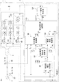
- FIG. 1 is an overall configuration diagram of the power conversion device
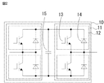
- FIGS. 2 and 3 are circuit diagrams of unit cells
- the converter control unit 4 is a block diagram
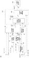
- FIG. 5 is a block diagram of a phase DC voltage control unit
- FIG. 6 is a block diagram of a total voltage control unit
- FIG. 7 is a block diagram of a negative phase current command value calculation unit
- an output current control unit 8 is a block diagram of the circulating current control unit
- FIG. 10 is a block diagram of the voltage command value calculation unit
- FIG. 11 is a block diagram of the cell DC voltage control unit. .
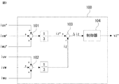
- FIG. 1 shows a configuration of an entire system including a power conversion device 1 according to Embodiment 1 of the present invention.
- the entire system includes a power conversion device 1, an AC power system 2, and a transformer 3, and the power conversion device 1 is connected in parallel to the AC power system 2 via the transformer 3.
- the power converter device 1 is connected to the alternating current power grid
- the power conversion device 1 includes a power conversion unit 6 and a converter control unit 7.
- the power conversion unit 6 includes an arm 4 in each phase, and each arm 4 is formed by connecting a plurality of unit cells 10 and an arm reactor 5 in series.
- the arm 4 of each phase is connected by delta connection, and the connection end of each phase arm is connected to the AC power system 2.
- the arm reactor 5 is inserted to suppress a circulating current component, which will be described later, and the insertion position is limited to the position shown in FIG. 1 as long as it is connected in series with the unit cell 10. In addition, a plurality may be inserted in a distributed manner.
- the power conversion unit 6 includes an arm current detection unit 40 that detects the current of each arm 4. Furthermore, a DC capacitor voltage detector 50 that detects the voltage of the DC capacitor 15 of the unit cell 10 described later is provided.
- the power conversion unit 6 receives a voltage signal from the AC voltage detection unit 20 that detects the AC voltage of the AC power system 2, and further detects a current from the output current detection unit 30 that detects the output current of the AC power system 2. Receive a signal.
- the configuration of the converter control unit 7 in FIG. 1 is mainly described with respect to the exchange of signals with the AC power system 2 and the power conversion unit 6, and thus a part of the configuration unit is omitted.
- the configuration and function of the converter control unit 7 will be described later with reference to FIG.
- FIG. 2 is a circuit diagram showing the internal configuration of the unit cell 10.
- the unit cell 10 constituted by a full bridge has two series bodies 11 each composed of a self-extinguishing type switching element 13 such as an IGBT (Insulated-Gate Bipolar Transistors) connected in parallel, and further has a DC capacitor 15 in parallel. It is a connected configuration.
- the serial body 11 is formed by connecting a plurality (in this case, two) of semiconductor switches 12 including diodes 14 connected in reverse parallel to the switching element 13 in series. Then, as shown in FIG.
- the unit cell 10 has a terminal of the semiconductor switch 12 serving as an internal intermediate connection point of each series body 11 as an output end, and the switching element 13 is turned on / off to turn off the output end.
- the same polarity, reverse polarity voltage or zero voltage of the DC capacitor 15 is output.
- FIG. 3 is a circuit diagram showing an internal configuration of the unit cell 10 configured by a half bridge.
- the unit cell 10 is composed of a serial body 11 composed of switching elements 13 and a DC capacitor 15 connected in parallel to the serial body 11.
- the serial body 11 is formed by serially connecting a plurality (two in this case) of semiconductor switches 12 including diodes 14 connected in antiparallel to the switching element 13.
- the unit cell 10 has both terminals of one semiconductor switch 12 as output terminals, and the switching element 13 is turned on / off, so that the same polarity voltage or zero of the DC capacitor 15 is output from this output terminal. Output voltage.
- the unit cell 10 is composed of a series body constituted by semiconductor switches and a DC capacitor connected in parallel to the series body, and a DC capacitor voltage is selectively output to an output terminal by the semiconductor switch of the series body.
- the configuration is not limited to FIGS. 2 and 3.
- unit cell will be referred to as “cell” as appropriate.
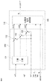
- FIG. 4 is an overall block diagram of converter control unit 7 for controlling power conversion unit 6 according to Embodiment 1 of the present invention.
- the converter control unit 7 includes three voltage control systems (phase DC voltage control unit 60, total voltage control unit 70, cell DC voltage control unit 140) and two current control systems (output current control unit 90) as main components. , Circulating current control unit 100), and further two operation units (reverse phase current command value calculation unit 80, phase voltage command value calculation unit 130).
- a function unit in which the phase voltage command value calculation unit 130 and the cell DC voltage control unit 140 are combined is used as a voltage command value calculation unit 110.
- the output current control unit 90 performs power control of the power conversion unit 6 by controlling the effective current iq and the reactive current id.
- the positive phase current command values id * and iq * are constituted by a positive phase reactive current command value id * and a positive phase active current command value iq * , and are predetermined values determined from the operating conditions of the power converter 1.
- the positive phase active current command value iq * is calculated by, for example, the all voltage control unit 70
- the positive phase reactive current command value id * is calculated from, for example, the positive phase voltage of the AC power system 2.
- the circulating current control unit 100 balances the DC capacitor voltage between the phases by controlling the current circulating in the delta connection.
- the circulating current command value iz * for controlling the circulating current is calculated by the phase DC voltage control unit 60.
- the cell DC voltage control unit 140 controls the DC capacitor voltage of each cell.
- the output voltage command value vcell * is the voltage command values vd * and vq * including both the positive phase component and the negative phase component output from the output current control unit 90, and the zero phase voltage command output from the circulating current control unit 100. It is calculated based on the value vz * , each cell DC voltage vcell, and arm currents iuv, ivw, iwu. Note that “DC capacitor voltage” is appropriately described as “DC voltage”.
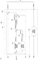
- FIG. 5 is a block diagram showing an internal configuration of phase DC voltage control unit 60 of converter control unit 7 of power conversion device 1 according to the first embodiment.
- the phase DC voltage controller 60 includes a voltage calculator 61, an estimated converter voltage calculator 62, a subtractor 63, a controller 64, a multiplier 65, and a filter 66.
- the voltage calculation unit 61 performs a representative voltage value vdc such as an average value, maximum value or minimum value of all cell DC capacitor voltages from the all cell DC capacitor voltage vdccell, and representative values vuv, vvw of each phase voltage. , Vwu are calculated based on each cell DC voltage vdccell.
- the subtractor 63 calculates errors ⁇ vuv, ⁇ vvw, ⁇ vwu between the representative value vdc of the all-cell DC capacitor voltage and the representative values vuv, vvw, vwu of each phase voltage.
- the controller 64 sets each phase current command value so that the errors ⁇ vuv, ⁇ vvw, ⁇ vwu become zero, that is, causes the representative values vuv, vvw, vwu of each phase voltage to follow the representative value vdc of all cell DC capacitor voltages. Is calculated. Further, since the representative values vuv, vvw, and vwu of each phase voltage vibrate at 2f (f is the fundamental frequency), the AC component of 2f is removed by the filter 66 before being input to the subtractor 63, and only the DC component is obtained. It is said.
- the arm current command value is calculated by multiplying the output of the controller 64 by the output voltage of each arm 4.
- the power converter 1 does not have a mechanism for detecting the output voltage of each arm 4
- the estimated converter voltages varmuv and varmvw having the same phase as the output voltage of each arm 4 are detected using a detection value such as a system voltage.
- Varmwu is calculated.
- the multiplier 65 calculates a product of components (estimated converter voltage) varuv, varmvw, varmwu having the same phase as the voltage of the transformer 3 and the output of the controller 64.
- the estimated converter voltages varnuv, varmw, and varmwu values obtained by calculating the line voltage by the estimated converter voltage calculator 62 from the system voltages vu, vv, and vw are used. That is, the arm current command values iuv * , ivw * , and iwu * that are outputs of the phase DC voltage control unit 60 are values obtained by multiplying the output of the controller 64 and the estimated converter voltage.
- FIG. 6 is a block diagram showing an internal configuration of total voltage control unit 70 of power conversion device 1 according to the first embodiment of the present invention.
- the total voltage control unit 70 includes a DC voltage representative value calculation unit 71, a subtracter 72, and a controller 73.
- a DC voltage representative value calculation unit 71 calculates a voltage representative value vdc such as an average value, a maximum value, or a minimum value of the all cell DC capacitor voltage from the all cell DC capacitor voltage vdccell.
- the subtractor 72 calculates an error ⁇ vdc between the DC total voltage command value vdc * and the voltage representative value vdc calculated by the DC voltage representative value calculation unit 71.
- the direct current total voltage command value vdc * is set to 1.
- the controller 73 calculates the positive phase active current command value iq * so that the calculated error ⁇ vdc becomes zero, that is, the representative value vdc of the all-cell DC capacitor voltage follows the DC total voltage command value vdc *. To do.
- the DC capacitor voltage of all cells is controlled to be constant.
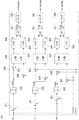
- FIG. 7 is a block diagram showing an internal configuration of the negative phase current command value calculation unit 80 of the power conversion device 1 according to the first embodiment of the present invention.
- the negative phase current command value calculation unit 80 includes subtractors 81 and 85, an adder 82, a three-phase / two-phase coordinate conversion unit 83, and a filter 84.
- the arm current command value iuv *, IVW *, negative sequence current command value from the IWU * idn * calculates the iqn *.
- the negative phase current command values idn * and iqn * are composed of a negative phase reactive current command value idn * and a negative phase active current command value iqn * .
- the arm current command values iuv * , ivw * , iwu * which are outputs of the phase DC voltage control unit 60, are added by the adder 82, and divided by 3, to calculate the circulating current command value iz * .
- the subtractor 81 calculates the difference ⁇ iuv * , ⁇ ivw * , ⁇ iwu * between the arm current command values iuv * , ivw * , iwu * and the circulating current command value iz * , which is the output of the phase DC voltage control unit 60, to obtain a positive value.
- the three-phase / two-phase coordinate conversion unit 83 performs three-phase / two-phase coordinate conversion on the extracted normal phase component and reverse phase component using the normal phase coordinate system.
- the subtractor 85 calculates the negative phase current command values idn * and iqn * by subtracting the output of the filter 84 that extracts the positive phase component from the output of the three-phase / two-phase coordinate conversion unit 83.
- the filter 84 used for normal phase component extraction has a function of extracting the positive phase component by removing the negative phase component from the filter input value.
- the positive phase component is a direct current component and the negative phase component is a frequency component (2f) that is twice the fundamental frequency, so a first order lag, 2f moving average, 2f notch filter, or the like is used.
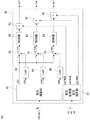
- FIG. 8 is a block diagram showing an internal configuration of output current control unit 90 of power conversion device 1 according to the first embodiment of the present invention.
- the output current control unit 90 includes a reference voltage calculation unit 91, a three-phase / two-phase coordinate conversion unit 92, and an adder 93.
- the reference voltage calculation unit 91 includes a three-phase / two-phase coordinate conversion unit 94, an adder 95, a subtractor 96, and a controller 97.
- the adder 95 adds the positive phase current command values id * , iq * and the negative phase current command values idn * , iqn * to calculate the current command values idpn * , iqpn * .
- idpn * id * + idn * (1)
- iqpn * iq * + iqn * (2)
- the three-phase / two-phase coordinate conversion unit 94 calculates a positive-phase reactive current id and a positive-phase effective current iq obtained by three-phase / two-phase conversion of the output currents iu, iv, and iw in the positive-phase coordinate system.
- the subtractor 96 calculates errors ⁇ id and ⁇ iq between the current command values idpn * and iqpn * and the positive phase reactive current id and the positive phase active current iq that are the outputs of the three-phase / two-phase coordinate conversion unit 94.
- the controller 97 calculates so that the calculated errors ⁇ id and ⁇ iq become zero, that is, the positive phase reactive current id and the positive phase active current iq follow the current command values idpn * and iqpn *.
- the negative phase reference voltages vdref and vqref are output.
- the three-phase / two-phase coordinate conversion unit 92 calculates positive phase voltages vd, vq obtained by three-phase / two-phase conversion of the system voltages vu, vv, vw in the positive phase coordinate system.
- the output current control unit 90 adds the positive phase voltages vd and vq to the positive phase negative phase reference voltages (vdref and vqref) output from the controller 97 in a feedforward manner by an adder 93 to obtain a positive phase component and Voltage command values vd * and vq * including both negative phase components are calculated.
- the voltage command values vd * and vq * including both the positive phase component and the negative phase component are the reactive voltage command value vd * including both the positive phase component and the negative phase component, and both the positive phase component and the negative phase component.
- FIG. 9 is a block diagram showing an internal configuration of circulating current control unit 100 of power conversion device 1 according to Embodiment 1 of the present invention.
- the circulating current control unit 100 includes adders 101 and 102, a subtractor 103, and a controller 104.
- arm current command values iuv * , ivw * , iwu * which are outputs of phase DC voltage control unit 60, are added by adder 101, and divided by 3, to calculate circulating current command value iz * . .
- the arm current values iuv, ivw, iwu are added by the adder 102, and divided by 3, to calculate the circulating current iz.
- the subtractor 103 calculates an error ⁇ iz between the circulating current command value iz * and the circulating current iz.
- the controller 104 calculates a zero-phase voltage command value vz * so that the error ⁇ iz becomes zero, that is, the circulating current iz follows the circulating current command value iz * .
- FIG. 10 shows an internal configuration of the voltage command value calculation unit 110.
- Voltage command value calculation unit 110 includes phase voltage command value calculation unit 130 and cell DC voltage control unit 140.
- the phase voltage command value calculation unit 130 includes a two-phase / three-phase coordinate conversion unit 131 and an adder 132.
- the internal configuration of the cell DC voltage control unit 140 will be described later.
- the voltage command value calculation unit 110 includes voltage command values vd * , vq * , a zero phase voltage command value vz * including both a positive phase component and a negative phase component, each cell DC voltage vdccell, and each phase arm current iuv, Based on ivw and iwu, the output voltage command value vcell * of each unit cell 10 is calculated.
- the phase voltage command value calculation unit 130 calculates the arm voltage command value of each phase, and the cell DC voltage control unit 140 calculates the output voltage command value of each cell.
- the two-phase / three-phase coordinate conversion unit 131 converts the voltage command values vd * and vq * including both the normal phase component and the reverse phase component into three phases in the normal phase coordinate system.
- the adder 132 adds the zero-phase voltage command value vz * to the voltage command value including both the normal phase component and the reverse phase component converted into the three phases, and each phase arm voltage command value vuv * , vvw *. , Vwu * is calculated.
- the cell DC voltage control unit 140 outputs the output of each cell based on each phase arm voltage command value vuv * , vvw * , vwu * , arm current iuv, ivw, iwu, and each cell DC voltage vdccell.
- the voltage command value vcell * is calculated.
- FIG. 11 is a block diagram showing the internal configuration of the cell DC voltage controller 140.
- the cell DC voltage control unit 140 includes a cell individual control unit 141 having N cells.
- the cell individual control unit 141 includes a phase representative value calculation unit 142, a cell voltage extraction unit 143, a filter 144, subtracters 145 and 148, a controller 146, and a multiplier 147.
- the phase representative value calculation unit 142 calculates each phase voltage representative value vdcubav such as the DC capacitor voltage average value, maximum value, or minimum value of each phase from each cell DC voltage vdccell. Further, the cell voltage extraction unit 143 calculates each cell DC voltage vdcuv1 from each cell DC voltage vdccell. The filter 144 removes the AC component of the frequency 2f from each cell DC voltage vdcuv1 and calculates vdcuvf1. The subtractor 145 subtracts vdcuvf1 from each phase voltage representative value vdcuvav to calculate an error ⁇ vdcuv1. The controller 146 calculates vdcuv1ref so that the calculated error ⁇ vdcuv1 becomes zero.
- the multiplier 147 multiplies the arm current iuv in phase with the control output vdcuv1ref.
- Each cell DC voltage command value vdcuv1 * is calculated by subtracting the output of the multiplier 147 from each phase arm voltage command value vuv * by a subtractor 148.
- vdccu1 * to vdcwuN * are output voltage command values vcell * of each cell.
- the gate signal generation unit 120 performs PWM control based on the output voltage command value vcell * of each cell, which is an output of the voltage command value calculation unit 110, and generates a gate signal for controlling on / off driving of the switching element 13 of each cell. Calculate.
- the power conversion device of the first embodiment includes a power conversion unit and a converter control unit
- the converter control unit includes three voltage control systems (phase DC voltage control unit, total voltage control unit, cell).
- DC voltage control unit DC voltage control unit
- two current control systems output current control unit, circulating current control unit
- two calculation units reverse phase current command value calculation unit, phase voltage command value calculation unit
- gate signal A generation unit and is configured to control the unbalance of each cell DC voltage between phases due to system imbalance by the circulating current and the negative phase current.
- the power converter device of Embodiment 1 suppresses the increase in the unit cell current with respect to a steady state at the time of system
- the positive phase effective current command value is calculated and generated from the all cell DC capacitor voltage and the DC total voltage command value by the all voltage control unit 70 shown in FIG. 4 has been described.
- the host control system may calculate the positive phase reactive current command value from the voltage of the system power supply, and the power converter may receive and use the positive phase reactive current command value from the host control system.
- FIG. The power conversion device according to the second embodiment has a configuration in which a function unit for controlling a reverse phase current is further added to the output current control unit of the power conversion device according to the first embodiment.
- FIG. 12 is a configuration diagram of the controller 297, with a focus on differences from the first embodiment.
- the overall configuration of the power conversion device of the second embodiment is the same as that of the power conversion device 1 of the first embodiment.
- the configuration of the controller 97 of the output current control unit 90 is different, and in order to distinguish it from the controller 97 of the first embodiment, the controller 297 is shown in FIG.
- the only difference between the converter control unit (output current control unit) of the second embodiment and the converter control unit (output current control unit) of the first embodiment is the configuration and function of the controller 297. Since other parts are the same as those in the first embodiment, the description thereof is omitted.
- the controller 297 includes a comparator 201, integrators 202 and 206, adders 203 and 208, two-phase / two-phase coordinate conversion units 204 and 207, and a filter 205.
- the output current control unit including the controller 297 is a voltage command value including both the positive phase component and the negative phase component so that the errors ⁇ id and ⁇ iq from the subtractor 96 of FIG. 8 described in the first embodiment become zero.
- vd * and vq * are calculated. That is, the voltage command values vd * and vq * including both the positive phase component and the negative phase component are calculated so that the positive phase reactive current id and the positive phase active current iq follow the current command values idpn * and iqpn * .
- the steady-state deviations ⁇ did and ⁇ diq which are the outputs of the comparator 201, include a positive phase component and a negative phase component, which are controlled by the integrators 202 and 206, respectively.
- the anti-phase component the output of the comparator 201 is coordinate-converted into the anti-phase coordinate system by the two-phase / two-phase coordinate conversion unit 204, and the anti-phase component is extracted by the filter 205.
- the extracted anti-phase component is controlled by the integrator 206, and the output is coordinate-converted into a normal-phase coordinate system by the two-phase / two-phase coordinate conversion unit 207.
- the anti-phase component is also controlled.
- the negative phase The current can be controlled according to the command value.
- the power conversion device of the second embodiment has a configuration in which a function unit for controlling a reverse phase current is further added to the output current control unit of the power conversion device of the first embodiment. For this reason, since the increase of the unit cell current with respect to a steady state at the time of system
- Embodiment 3 FIG.
- the power converter of Embodiment 3 is configured to include a normal phase current control unit and a negative phase current control unit in the output current control unit.
- FIG. 13 is a configuration diagram of the reference voltage calculation unit 391.
- the overall configuration of the power conversion device according to the third embodiment is the same as that of power conversion device 1 according to the first embodiment.
- the configuration of the reference voltage calculation unit 391 of the output current control unit is different, and in order to distinguish it from the reference voltage calculation unit 91 of the first embodiment, the reference voltage calculation unit 391 is illustrated in FIG.
- the only difference between the output current control unit of the third embodiment and the output current control unit of the first embodiment is the configuration and function of the reference voltage calculation unit 391. Since other parts are the same as those in the first embodiment, the description thereof is omitted.
- the reference voltage calculation unit 391 includes a normal phase current control unit 301, a reverse phase current control unit 302, three-phase / two-phase coordinate conversion units 303 and 304, and an adder 305.
- the positive phase current control unit 301 includes a subtractor 306 and a controller 307
- the negative phase current control unit 302 includes a subtractor 308 and a controller 309.
- the positive phase current control unit 301 uses the subtractor 306 to calculate the positive phase current command values id * , iq * , the positive phase reactive current id, and the errors ⁇ id, ⁇ iq of the positive phase active current iq. Further, the controller 307 corrects the calculated errors ⁇ id and ⁇ iq so as to be zero, that is, the positive phase reactive current id and the positive phase active current iq follow the positive phase current command values id * and iq *. Phase effective / reactive voltage command values vd1 * and vq1 * are calculated.
- the negative phase current control unit 302 uses the subtractor 308 to calculate the negative phase current command values idn * , iqn * , the negative phase reactive current idn, and the errors ⁇ idn, ⁇ iqn of the negative phase active current iqn. Further, the controller 309 causes the calculated errors ⁇ idn and ⁇ iqn to become zero, that is, the negative-phase reactive current idn and the negative-phase active current iqn follow the negative-phase current command values idn * and iqn *. Valid / invalid voltage command values vdn * and vqn * are calculated.
- the three-phase / two-phase coordinate conversion unit 303 calculates a positive-phase reactive current id and a positive-phase effective current iq obtained by three-phase / two-phase conversion of the output currents iu, iv, and iw in the positive-phase coordinate system. Further, the three-phase / two-phase coordinate conversion unit 304 calculates a negative-phase reactive current idn and a negative-phase effective current iqn obtained by three-phase / two-phase conversion of the output currents iu, iv, and iw in the negative-phase coordinate system.
- the output current control unit includes the negative phase current control unit, thereby controlling the negative phase current according to the command value in addition to the effect of the power conversion device according to the first embodiment. It becomes possible.
- the power conversion device of the third embodiment has a configuration in which an output current control unit includes a normal phase current control unit and a negative phase current control unit. For this reason, since the increase of the unit cell current with respect to a steady state at the time of system
- Embodiment 4 The power conversion device according to the fourth embodiment is configured to include a mechanism for detecting an arm output voltage.
- FIG. 14 is an overall configuration diagram of the power conversion device.
- FIG. 14 is an overall configuration diagram of the power conversion device.
- the overall configuration of the power conversion device of the fourth embodiment is the same as that of the power conversion device 1 of the first embodiment, except that it includes an arm output voltage detection unit 408 that detects an arm output voltage.
- it is set as the power converter 401, the power converter 406, the converter control part 407, and the phase DC voltage control part 460 in FIG.
- the only difference between the power conversion device of the fourth embodiment and the power conversion device of the first embodiment is that it includes an arm output voltage detection unit 408 that detects an arm output voltage. Since other parts are the same as those in the first embodiment, the description thereof is omitted.
- the arm output voltage detector 408 detects the arm output voltage.
- the phase DC voltage control unit 460 multiplies the detected arm output voltage by the multiplier 65 with the output of the controller 64 of FIG. 5 described in the first embodiment, so that the arm current command values iuv * , ivw * , iwu * Is calculated. That is, in the phase DC voltage control unit 460, the estimated converter voltage varmuv, varmvw, varmwu is not calculated by the estimated converter voltage calculation unit 62 of FIG. 5, but the arm output voltage detected by the arm output voltage detection unit 408 is calculated. Use.
- the power conversion device by using the actual arm output voltage as the estimated converter voltage varmuv, varmvw, varmwu, in addition to the effects of the first embodiment, The accuracy of voltage control is further improved.
- the power conversion device is configured to include a mechanism for detecting the arm output voltage. For this reason, since the increase of the unit cell current with respect to a steady state at the time of system
- Embodiment 5 FIG.
- the power converter of Embodiment 5 is configured to take into account the voltage drop from the transformer to the cell output terminal when the estimated value of each arm output voltage is calculated by the phase DC voltage controller.
- FIG. 15 is a block diagram illustrating the configuration of the estimated converter voltage calculation unit 562. The difference from Embodiments 1 and 4 will be mainly described.
- the overall configuration of the power conversion device of the fifth embodiment is the same as that of the power conversion device 1 of the first embodiment.
- a specific configuration example of the estimated converter voltage calculation unit is shown, and in order to distinguish from the estimated converter voltage calculation unit 62 of the first embodiment, the estimated converter voltage calculation unit in FIG. 562. Since the fifth embodiment shows a specific configuration example of the estimated converter voltage calculation unit, the configuration and function of the estimated converter voltage calculation unit 562 will be described.
- the estimated converter voltage calculation unit 562 includes subtractors 501, 503, multipliers 502, 504, and calculators 505, 506, 507.
- the voltage difference between the system voltages is calculated from the system voltages vu, vv, and vw by the subtractor 501 and is multiplied by 1 / ⁇ 3 by the multiplier 502 to calculate the system line voltages vsuv, vsvw, and vswu.
- a multiplier 504 multiplies the positive phase reactive current command value id * by the reactance X of the transformer 3 to calculate a voltage drop.
- the subtracter 503 subtracts the voltage drop from the system line voltages vsuv, vsvw, and vswu. As a result, estimated converter voltages varmuv, varmvw, varmwu are calculated.
- the accuracy of voltage control of the power conversion device according to the fourth embodiment is calculated by considering the voltage drop from the system voltage in the calculation of the estimated converter voltages varmuv, varmvw, and varmwu. In addition to the effect of improving, the mechanism for detecting the arm output voltage becomes unnecessary.
- the power conversion device is configured to take into account the voltage drop of the transformer when calculating the estimated value of each arm output voltage in the phase DC voltage control unit. For this reason, since the increase of the unit cell current with respect to a steady state at the time of system
- Embodiment 6 FIG.
- the power conversion device is configured such that the estimated converter voltage calculation unit of the phase DC voltage control unit includes a single-phase detection function unit.
- FIG. 16 is a block diagram showing the configuration of the estimated converter voltage calculation unit 662. A description will be given centering on differences from the fifth embodiment.
- the overall configuration of the power conversion device according to the sixth embodiment is the same as that of power conversion device 1 according to the first embodiment.
- another specific configuration example of the estimated converter voltage calculation unit is shown. To distinguish from the estimated converter voltage calculation unit 562 of the fifth embodiment, the estimated converter voltage in FIG. The calculation unit 662 is used. Since Embodiment 6 shows another specific configuration example of the estimated converter voltage calculation unit, the configuration and function of the estimated converter voltage calculation unit 662 will be described.
- the estimated converter voltage calculation unit 662 includes a subtractor 601, multipliers 602, 603, and 604, a two-phase / two-phase coordinate conversion unit 605, a filter 606, and calculators 607 and 608.
- the voltage difference between the system voltages is calculated from the system voltages vu, vv, and vw by the subtractor 601 and multiplied by 1 / ⁇ 3 by the multiplier 602 to calculate the system line voltages vsuv, vsvw, and vswu.
- Grid line voltage vsuv, vsvw, sin ⁇ to vswu L, cos ⁇ L (where, as reference phase of ⁇ , ⁇ L ⁇ + ⁇ / 6) by multiplying by the multiplier 603 and 604, and line wire using a reference phase
- a signal having a phase difference of 90 degrees is calculated with respect to the inter-voltages vsuv, vsvw, vswu.
- the output signals of the multipliers 603 and 604 are subjected to rotational coordinate conversion from the normal phase coordinate system by the two-phase / two-phase coordinate conversion unit 605. Thereafter, filtering is performed by the filter 606 to detect a voltage vector having a single-phase phase that does not include harmonics.
- the computing unit 607 computes the phase ⁇ from the voltage vector, and the computing unit 608 computes the estimated converter voltages varmuv, varmvw, varmwu.
- the power conversion device has a single-phase phase detection function in the estimated converter voltage calculation unit, detects a single-phase phase voltage vector that does not include harmonics, and based on this, the estimated converter Voltages varmuv, varmvw, varmwu are calculated. For this reason, the synchronization accuracy of the phase of the reference voltage is improved, and the arm current maximum value at the time of unbalance can be reduced.
- the power conversion device of the sixth embodiment is configured such that the estimated converter voltage calculation unit of the phase DC voltage control unit has a single-phase detection function. For this reason, since the increase of the unit cell current with respect to a steady state at the time of system
- the present invention relates to a power converter that can reduce the current flowing through the power converter when the system is unbalanced, and can be widely applied to a large power converter.
Abstract
Description
変換器を多重化する方法は、様々存在し、リアクトル多重や変圧器多重、直接多重などがある。変圧器で多重化すると、交流側は変圧器で絶縁されるため各変換器の直流を共通化できるというメリットがある。しかし、出力電圧が高電圧となると多重変圧器の構成が複雑となる点および変圧器のコストが高くなる点がデメリットである。(例えば、特許文献1)。 Large-capacity power converters are often configured by multiplexing a plurality of converters in series or in parallel because the converter output becomes a high voltage or a large current. Multiplexing converters not only increases the converter capacity, but also synthesizes the output to reduce harmonics contained in the output voltage waveform and reduce the harmonic current that flows out of the converter. It is known to do.
There are various methods for multiplexing converters, including reactor multiplexing, transformer multiplexing, and direct multiplexing. When multiplexed by a transformer, the AC side is insulated by the transformer, so that there is an advantage that the DC of each converter can be shared. However, when the output voltage is high, the configuration of the multiple transformer becomes complicated and the cost of the transformer increases. (For example, patent document 1).
三相MMCはアームの結線方法により様々な構成が可能であり、その中の1つの変換器構成として、デルタ結線カスケード方式がある。デルタ結線カスケード変換器は、複数の単位セルをカスケード接続し、更にリアクトルを直列接続したアームをデルタ結線した構成であり、リアクトルまたは変圧器を介し、交流電力系統に並列接続した構成である。そのため、系統から相間を流れる電流と、系統側には出力されず変換器のデルタ結線内を循環する電流の2つの電流成分が存在する。したがって、三相MMCでは、これらの電流成分を制御する必要がある。また、各々のセルには直流コンデンサが構成されており、この直流コンデンサは電源を持たないため、電圧を一定の範囲内に制御する必要がある。 The MMC is composed of an arm in which a plurality of unit converters called cells (hereinafter referred to as unit cells) are cascade-connected. The unit cell includes a plurality of semiconductor switches and a DC capacitor, and outputs a voltage across the DC capacitor or a zero voltage by turning on and off the semiconductor switch.
The three-phase MMC can be configured in various ways depending on the arm connection method, and one of the converter configurations is a delta connection cascade system. The delta connection cascade converter has a configuration in which a plurality of unit cells are connected in cascade, and an arm in which reactors are connected in series is connected in delta connection, and is connected in parallel to an AC power system via a reactor or a transformer. For this reason, there are two current components, a current flowing between the phases from the system and a current circulating in the delta connection of the converter that is not output to the system side. Therefore, it is necessary to control these current components in the three-phase MMC. Each cell is provided with a DC capacitor. Since this DC capacitor does not have a power supply, it is necessary to control the voltage within a certain range.
特許文献1の開示発明では、不平衡率が高い系統事故においては相間の直流コンデンサ電圧をバランスさせるために大きな循環電流を流す必要があり、変換器、すなわち電力変換部に流れる電流が大きくなるという問題があった。 A characteristic of the three-phase MMC is that the DC capacitor voltage is constant and balanced because control is performed so that a reactive current having a phase difference of 90 degrees flows from the system voltage when the system is balanced. However, since the same current as in the balanced state flows to the unbalanced system voltage when the system is unbalanced, the effective current flows through the system voltage, so that the capacitor is charged and discharged and unbalanced. Therefore, the DC voltage is unbalanced during unbalance.
In the disclosed invention of
実施の形態1は、電力変換部と変換器制御部を備え、変換器制御部は3つの電圧制御系(相直流電圧制御部、全電圧制御部、セル直流電圧制御部)と、2つの電流制御系(出力電流制御部、循環電流制御部)と、2つの演算部(逆相電流指令値演算部、相電圧指令値演算部)と、さらにゲート信号生成部とを備え、系統不平衡による相間の各セル直流電圧のアンバランスを循環電流と逆相電流により制御する電力変換装置に関するものである。
The first embodiment includes a power conversion unit and a converter control unit, and the converter control unit includes three voltage control systems (phase DC voltage control unit, total voltage control unit, cell DC voltage control unit) and two currents. A control system (output current control unit, circulating current control unit), two calculation units (reverse phase current command value calculation unit, phase voltage command value calculation unit), and a gate signal generation unit are provided. The present invention relates to a power converter that controls the imbalance of each cell DC voltage between phases by circulating current and reverse phase current.
なお、図1では、電力変換装置1は変圧器3を介して交流電力系統2に接続されているが、連系リアクトルを介して接続される構成であってもよい。 FIG. 1 shows a configuration of an entire system including a
In addition, in FIG. 1, although the
アームリアクトル5は、後述する循環電流成分を抑制するために挿入するもので、単位セル10と直列に接続されるものであれば、その挿入位置は、図1に示された位置に限られるものではなく、また、複数個を分散して挿入するものであってもよい。
電力変換部6は、各アーム4の電流を検出するアーム電流検出部40を備える。さらに後で説明する単位セル10の直流コンデンサ15の電圧を検出する直流コンデンサ電圧検出部50を備える。また、電力変換部6は、交流電力系統2の交流電圧を検出する交流電圧検出部20からの電圧信号を受信し、さらに交流電力系統2の出力電流を検出する出力電流検出部30からの電流信号を受信する。 The
The
The
図2は、単位セル10の内部構成を示す回路図である。フルブリッジで構成されている単位セル10は、IGBT(Insulated-Gate Bipolar Transistors)等の自己消弧型のスイッチング素子13から構成される直列体11を2つ並列接続し、さらに直流コンデンサ15を並列接続した構成である。直列体11は、このスイッチング素子13に逆並列に接続されたダイオード14からなる半導体スイッチ12を複数(ここでは、2つ)直列接続したものである。そして、単位セル10は図2に示すように、それぞれの直列体11の内部中間接続点となる半導体スイッチ12の端子を出力端とし、スイッチング素子13をオン・オフさせることにより、この出力端から直流コンデンサ15の同極性、逆極性電圧またはゼロ電圧を出力する。 Next, a specific internal configuration of the
FIG. 2 is a circuit diagram showing the internal configuration of the
なお、以降「単位セル」を適宜、「セル」と記載する。 The
Hereinafter, “unit cell” will be referred to as “cell” as appropriate.
出力電流制御部90では、有効電流iqと無効電流idを制御することで、電力変換部6の電力制御を行っている。正相電流指令値id*、iq*は、正相無効電流指令値id*と正相有効電流指令値iq*で構成され、電力変換装置1の運転条件から定まる所定の値である。ここで、正相有効電流指令値iq*は、例えば全電圧制御部70で演算され、正相無効電流指令値id*は、例えば交流電力系統2の正相電圧から演算される。
循環電流制御部100では、デルタ結線内を循環する電流を制御することで、相間の直流コンデンサ電圧をバランスさせている。循環電流を制御するための循環電流指令値iz*は、相直流電圧制御部60で演算される。
セル直流電圧制御部140では、各セルの直流コンデンサ電圧を制御している。出力電圧指令値vcell*は、出力電流制御部90の出力である正相成分と逆相成分の両方を含む電圧指令値vd*、vq*、循環電流制御部100の出力である零相電圧指令値vz*と、各セル直流電圧vcellおよびアーム電流iuv、ivw、iwuに基づいて演算される。
なお、「直流コンデンサ電圧」を適宜、「直流電圧」と記載する。 First, the functional outline of the
The output
The circulating
The cell DC
Note that “DC capacitor voltage” is appropriately described as “DC voltage”.
vu、vv、vw:系統電圧
iu、iv、iw:出力電流
iuv、ivw、iwu:アーム電流
vdccell:各セル直流電圧(N個:各アームのセル数n×3アーム)
iuv*、ivw*、iwu*:アーム電流指令値
id*、iq*:正相電流指令値
idn*、iqn*:逆相電流指令値
vd*、vq*:正相成分と逆相成分の両方を含む電圧指令値
vz*:零相電圧指令値
vcell*:出力電圧指令値(N個:各アームのセル数n×3アーム)
vuv*、vvw*、vwu*:アーム電圧指令値 When the configuration and function of each unit of the
vu, vv, vw: system voltage iu, iv, iw: output current iuv, ivw, iwu: arm current vdccell: DC voltage of each cell (N cells: number of cells in each arm n × 3 arm)
iuv * , ivw * , iwu * : arm current command value id * , iq * : positive phase current command value idn * , iqn * : negative phase current command value vd * , vq * : both positive phase component and negative phase component Vz * : Zero-phase voltage command value vcell * : Output voltage command value (N: number of cells in each arm n × 3 arms)
vuv * , vvw * , vwu * : Arm voltage command value
図5は、実施の形態1による電力変換装置1の変換器制御部7の相直流電圧制御部60の内部構成を示すブロック図である。
相直流電圧制御部60は、電圧演算部61、推定変換器電圧演算部62、減算器63、制御器64、乗算器65、およびフィルタ66から構成される。 Next, the configuration and operation of the phase
FIG. 5 is a block diagram showing an internal configuration of phase DC
The phase
また、各相電圧の代表値vuv、vvw、vwuは2f(fは基本周波数)で振動しているため、減算器63に入力する前にフィルタ66により2fの交流分を除去し、直流分のみとしている。 In the phase DC
Further, since the representative values vuv, vvw, and vwu of each phase voltage vibrate at 2f (f is the fundamental frequency), the AC component of 2f is removed by the
乗算器65は変圧器3の電圧と同位相の成分(推定変換器電圧)varmuv、varmvw、varmwuと制御器64の出力の積を演算する。ここで、推定変換器電圧varnuv、varmvw、varmwuは、系統電圧vu、vv、vwから推定変換器電圧演算部62で線間電圧を演算した値を用いる。つまり、相直流電圧制御部60の出力であるアーム電流指令値iuv*、ivw*、iwu*は、制御器64の出力と推定変換器電圧を乗算した値である。 In order to charge / discharge the
The
図6は、本発明の実施の形態1による電力変換装置1の全電圧制御部70の内部構成を示すブロック図である。全電圧制御部70は、直流電圧代表値演算部71、減算器72、および制御器73から構成される。 Next, the configuration and operation of the total
FIG. 6 is a block diagram showing an internal configuration of total
制御器73は、演算された誤差Δvdcがゼロとなるよう、すなわち、全セル直流コンデンサ電圧の代表値vdcを直流全電圧指令値vdc*に追従させるように正相有効電流指令値iq*を演算する。
電圧代表値に全セル直流コンデンサ電圧の平均値、および最大値または最小値の平均値のいずれかを用いることで、全セルの直流コンデンサ電圧が一定に制御される。 In the all
The
By using either the average value of all cell DC capacitor voltages and the average value of the maximum value or the minimum value as the voltage representative value, the DC capacitor voltage of all cells is controlled to be constant.
図7は本発明の実施の形態1による電力変換装置1の逆相電流指令値演算部80の内部構成を示すブロック図である。逆相電流指令値演算部80は、減算器81、85、加算器82、三相/二相座標変換部83、およびフィルタ84から構成される。 Next, the configuration and operation of the negative phase current command
FIG. 7 is a block diagram showing an internal configuration of the negative phase current command
相直流電圧制御部60の出力であるアーム電流指令値iuv*、ivw*、iwu*を加算器82で加算し、3で割って循環電流指令値iz*を演算する。
減算器81は、相直流電圧制御部60の出力であるアーム電流指令値iuv*、ivw*、iwu*と循環電流指令値iz*の差Δiuv*、Δivw*、Δiwu*を演算して、正相成分と逆相成分を抽出する。抽出した正相成分と逆相成分を三相/二相座標変換部83により、正相座標系で三相/二相座標変換する。
減算器85は、三相/二相座標変換部83の出力から正相成分を抽出するフィルタ84の出力を減算することで逆相電流指令値idn*、iqn*を演算する。
なお、正相成分抽出に用いるフィルタ84は、フィルタ入力値から逆相成分を除き、正相成分を抽出する機能を有する。正相座標系では正相成分は直流成分、逆相成分は基本波周波数の2倍周波数成分(2f)となるため、一次遅れ、2f移動平均、2fのノッチフィルタ等を用いる。 In the inverse-phase current command
The arm current command values iuv * , ivw * , iwu * , which are outputs of the phase DC
The
The
Note that the
図8は本発明の実施の形態1による電力変換装置1の出力電流制御部90の内部構成を示すブロック図である。出力電流制御部90は、基準電圧演算部91、三相/二相座標変換部92、および加算器93から構成される。そして基準電圧演算部91は、三相/二相座標変換部94、加算器95、減算器96および制御器97から構成される。 Next, the configuration and operation of the output
FIG. 8 is a block diagram showing an internal configuration of output
idpn*=id*+idn*(1)
iqpn*=iq*+iqn*(2)
三相/二相座標変換部94は、出力電流iu、iv、iwを正相座標系で三相/二相変換した正相無効電流id、正相有効電流iqを演算する。減算器96は、電流指令値idpn*、iqpn*と三相/二相座標変換部94の出力である正相無効電流id、正相有効電流iqとの誤差Δid、Δiqを演算する。
制御器97は、演算された誤差Δid、Δiqがゼロとなるよう、すなわち、正相無効電流id、正相有効電流iqを電流指令値idpn*、iqpn*に追従させるように演算し、正相逆相基準電圧vdref、vqrefを出力する。
三相/二相座標変換部92は、系統電圧vu、vv、vwを正相座標系で三相/二相変換した正相電圧vd、vqを演算する。
出力電流制御部90では、加算器93でこの正相電圧vd、vqをフィードフォワード的に制御器97の出力である正相逆相基準電圧(vdref、vqref)に加算して、正相成分と逆相成分の両方を含む電圧指令値vd*、vq*を演算する。なお、正相成分と逆相成分の両方を含む電圧指令値vd*、vq*は、正相成分と逆相成分の両方を含む無効電圧指令値vd*と正相成分と逆相成分の両方を含む有効電圧指令値vq*で構成される。 In the output
idpn * = id * + idn * (1)
iqpn * = iq * + iqn * (2)
The three-phase / two-phase coordinate
The
The three-phase / two-phase coordinate
The output
図9は本発明の実施の形態1による電力変換装置1の循環電流制御部100の内部構成を示すブロック図である。循環電流制御部100は、加算器101、102、減算器103、および制御器104から構成される。 Next, the configuration and operation of the circulating
FIG. 9 is a block diagram showing an internal configuration of circulating
減算器103は、循環電流指令値iz*と循環電流izの誤差Δizを演算する。制御器104は、この誤差Δizがゼロとなるよう、すなわち、循環電流izを循環電流指令値iz*に追従させるような零相電圧指令値vz*を演算する。 In circulating
The
図10は電圧指令値演算部110の内部構成を示す。電圧指令値演算部110は、相電圧指令値演算部130とセル直流電圧制御部140から構成される。
相電圧指令値演算部130は、二相/三相座標変換部131と加算器132から構成される。セル直流電圧制御部140の内部構成は後述する。
電圧指令値演算部110は全体として、正相成分と逆相成分の両方を含む電圧指令値vd*、vq*と零相電圧指令値vz*と各セル直流電圧vdccellと各相アーム電流iuv、ivw、iwuに基づき単位セル10それぞれの出力電圧指令値vcell*を演算する。 Next, the configuration and operation of the voltage command
FIG. 10 shows an internal configuration of the voltage command
The phase voltage command
As a whole, the voltage command
相電圧指令値演算部130では、二相/三相座標変換部131により正相成分と逆相成分の両方を含む電圧指令値vd*、vq*を正相座標系で三相に変換する。加算器132は、三相に変換された各正相成分と逆相成分の両方を含む電圧指令値に零相電圧指令値vz*をそれぞれ加算し、各相アーム電圧指令値vuv*、vvw*、vwu*を演算する。
詳細は後述するがセル直流電圧制御部140は、これら各相アーム電圧指令値vuv*、vvw*、vwu*とアーム電流iuv、ivw、iwu、および各セル直流電圧vdccellに基づき、各セルの出力電圧指令値vcell*を演算する。 The phase voltage command
In the phase voltage command
Although details will be described later, the cell DC
図11はセル直流電圧制御部140の内部構成を示すブロック図である。セル直流電圧制御部140は、セル数N個のセル個別制御部141を備える。セル個別制御部141は、相代表値演算部142、セル電圧抽出部143、フィルタ144、減算器145、148、制御器146、および乗算器147から構成される。 Next, the configuration and operation of the cell
FIG. 11 is a block diagram showing the internal configuration of the cell
さらに、制御出力vdcuv1refと同相のアーム電流iuvを乗算器147で乗算する。各相アーム電圧指令値vuv*から乗算器147の出力を減算器148で減算することで、各セル直流電圧指令値vdcuv1*を演算する。vdcuv1*からvdcwuN*が各セルの出力電圧指令値vcell*である。 In the cell
Further, the
本実施の形態1では、正相有効電流指令値を図4に示す全電圧制御部70で全セル直流コンデンサ電圧と直流全電圧指令値とから演算して生成する場合を説明した。しかし、電力変換装置の損失(例えばリアクトルの損失や単位セル内の半導体スイッチング素子の損失)をあらかじめ測定し、この測定値から正相有効電流指令値を算出して設定した値を用いてもよい。
また、正相無効電流指令値を電力変換装置内部で交流電力系統の正相電圧から演算する場合を説明した。しかし、上位制御システムで系統電源の電圧から正相無効電流指令値を演算し、電力変換装置は、上位制御システムからこの正相無効電流指令値を受信して、使用してもよい。 As described above, the power conversion device of the first embodiment includes a power conversion unit and a converter control unit, and the converter control unit includes three voltage control systems (phase DC voltage control unit, total voltage control unit, cell). DC voltage control unit), two current control systems (output current control unit, circulating current control unit), two calculation units (reverse phase current command value calculation unit, phase voltage command value calculation unit), and gate signal A generation unit, and is configured to control the unbalance of each cell DC voltage between phases due to system imbalance by the circulating current and the negative phase current. For this reason, since the power converter device of
In the first embodiment, the case where the positive phase effective current command value is calculated and generated from the all cell DC capacitor voltage and the DC total voltage command value by the all
Moreover, the case where the positive phase reactive current command value is calculated from the positive phase voltage of the AC power system inside the power converter has been described. However, the host control system may calculate the positive phase reactive current command value from the voltage of the system power supply, and the power converter may receive and use the positive phase reactive current command value from the host control system.
実施の形態2の電力変換装置は、実施の形態1の電力変換装置の出力電流制御部に逆相電流を制御する機能部をさらに追加した構成としたものである。
The power conversion device according to the second embodiment has a configuration in which a function unit for controlling a reverse phase current is further added to the output current control unit of the power conversion device according to the first embodiment.
実施の形態2の変換器制御部(出力電流制御部)が実施の形態1の変換器制御部(出力電流制御部)と異なっている部分は、制御器297の構成、機能のみである。他の部分は、実施の形態1の場合と同一であるので、説明は省略する。 The overall configuration of the power conversion device of the second embodiment is the same as that of the
The only difference between the converter control unit (output current control unit) of the second embodiment and the converter control unit (output current control unit) of the first embodiment is the configuration and function of the
比較器201の出力である定常偏差Δdid、Δdiqには正相成分と逆相成分が含まれており、それぞれを積分器202,206で制御する。逆相成分については比較器201の出力を二相/二相座標変換部204で逆相座標系へ座標変換し、フィルタ205で逆相成分を抽出する。そして抽出した逆相成分を積分器206で制御し、その出力を二相/二相座標変換部207で、正相座標系へと座標変換する。その演算結果を積分器202の出力に加算器208で加算することで、逆相成分も制御する。 The output current control unit including the
The steady-state deviations Δdid and Δdiq, which are the outputs of the
実施の形態3の電力変換装置は、出力電流制御部に正相電流制御部と逆相電流制御部とを備える構成としたものである。
The power converter of
実施の形態3の出力電流制御部が実施の形態1の出力電流制御部と異なっている部分は、基準電圧演算部391の構成、機能のみである。他の部分は、実施の形態1の場合と同一であるので、説明は省略する。 The overall configuration of the power conversion device according to the third embodiment is the same as that of
The only difference between the output current control unit of the third embodiment and the output current control unit of the first embodiment is the configuration and function of the reference
正相電流制御部301は、減算器306および制御器307から構成され、逆相電流制御部302は、減算器308および制御器309から構成されている。 In FIG. 13, the reference
The positive phase
また、逆相電流制御部302は、減算器308により逆相電流指令値idn*、iqn*と逆相無効電流idn、逆相有効電流iqnの誤差Δidn、Δiqnを演算する。さらに、制御器309は演算された誤差Δidn、Δiqnがゼロになるよう、すなわち、逆相無効電流idn、逆相有効電流iqnを逆相電流指令値idn*、iqn*に追従するように逆相有効・無効電圧指令値vdn*、vqn*を演算する。 The positive phase
Further, the negative phase
つまり、実施の形態3の出力電流制御部では、正相無効電流id、正相有効電流iqおよび逆相無効電流idn、逆相有効電流iqnそれぞれを個別に4軸で制御する。 Add the negative phase valid / invalid voltage command values vdn * and vqn * output from the negative phase
That is, in the output current control unit of the third embodiment, the positive phase reactive current id, the positive phase active current iq, the negative phase reactive current idn, and the negative phase active current iqn are individually controlled on four axes.
実施の形態4の電力変換装置は、アーム出力電圧を検出する機構を備える構成としたものである。
The power conversion device according to the fourth embodiment is configured to include a mechanism for detecting an arm output voltage.
なお、図14において、図1と同一あるいは相当部分には、同一の符号を付している。 Hereinafter, the configuration and operation of the power conversion device according to the fourth embodiment will be described focusing on differences from the first embodiment based on FIG. 14, which is an overall configuration diagram of the power conversion device.
In FIG. 14, the same or corresponding parts as in FIG.
実施の形態4の電力変換装置が実施の形態1の電力変換装置と異なっている部分は、アーム出力電圧を検出するアーム出力電圧検出部408を備えることのみである。他の部分は、実施の形態1の場合と同一であるので、説明は省略する。 The overall configuration of the power conversion device of the fourth embodiment is the same as that of the
The only difference between the power conversion device of the fourth embodiment and the power conversion device of the first embodiment is that it includes an arm output
実施の形態5の電力変換装置は、相直流電圧制御部で各アーム出力電圧の推定値を演算する際、変圧器からセル出力端までの電圧ドロップ分を考慮する構成としたものである。
The power converter of
実施の形態5は、推定変換器電圧演算部の具体的構成例を示したものであるため、推定変換器電圧演算部562の構成と機能を説明する。 The overall configuration of the power conversion device of the fifth embodiment is the same as that of the
Since the fifth embodiment shows a specific configuration example of the estimated converter voltage calculation unit, the configuration and function of the estimated converter
乗算器504で正相無効電流指令値id*に変圧器3のリアクタンスXを乗ずることで、電圧ドロップ分を演算する。この電圧ドロップ分に演算器505、506、507で基準位相θに対する位相差(2/3π、4/3π)を考慮して、減算器503で系統線間電圧vsuv、vsvw、vswuから減算する。この結果、推定変換器電圧varmuv、varmvw、varmwuが演算される。 The voltage difference between the system voltages is calculated from the system voltages vu, vv, and vw by the
A
実施の形態6の電力変換装置は、相直流電圧制御部の推定変換器電圧演算部に単相位相検出機能部を備える構成としたものである。
The power conversion device according to the sixth embodiment is configured such that the estimated converter voltage calculation unit of the phase DC voltage control unit includes a single-phase detection function unit.
実施の形態6は、推定変換器電圧演算部の他の具体的構成例を示したものであるため、推定変換器電圧演算部662の構成と機能を説明する。 The overall configuration of the power conversion device according to the sixth embodiment is the same as that of
Since
系統線間電圧vsuv、vsvw、vswuにsinωL、cosωL(ここで、θを基準位相として、ωL=θ+π/6)を乗算器603、604で乗ずることで、基準位相を用いて系統線間電圧vsuv、vsvw、vswuに対して、90度位相の異なる信号を演算する。乗算器603、604の出力信号を二相/二相座標変換部605で正相座標系から回転座標変換する。その後、フィルタ606によりフィルタリングを行うことで、高調波の含まない単相位相の電圧ベクトルを検出する。演算器607で電圧ベクトルから位相θを演算し、さらに演算器608で推定変換器電圧varmuv、varmvw、varmwuを演算する。 The voltage difference between the system voltages is calculated from the system voltages vu, vv, and vw by the
Grid line voltage vsuv, vsvw, sinω to vswu L, cosω L (where, as reference phase of θ, ω L = θ + π / 6) by multiplying by the
Claims (12)
- 三相の交流回路に接続される電力変換部と前記電力変換部を制御するための変換器制御部とを備え、
前記電力変換部は、前記交流回路に接続されデルタ結線された3つのアームを備え、
前記各アームは、1つまたは複数カスケード接続した単位セルとリアクトルとを直列に接続した構成であり、
前記単位セルは、互いに直列接続された複数の半導体スイッチの直列体とこの直列体と並列に接続された直流コンデンサとを備え、
前記変換器制御部は、前記各セルの直流コンデンサ電圧に基づき各相アーム電流指令値を演算する相直流電圧制御部と、
前記各相アーム電流指令値に基づき逆相電流指令値を演算する逆相電流指令値演算部と、
前記逆相電流指令値と所定の正相電流指令値とに基づき前記電力変換部の出力電流を制御する正相成分と逆相成分の両方を含む電圧指令値を演算する出力電流制御部と、
前記各相アーム電流指令値に基づいて循環電流を制御する零相電圧指令値を演算する循環電流制御部と、
前記正相成分と逆相成分の両方を含む電圧指令値と前記零相電圧指令値と前記各セル直流コンデンサ電圧と各相アーム電流に基づき前記単位セルそれぞれの出力電圧指令値を演算する電圧指令値演算部と、
前記出力電圧指令値に基づき前記単位セルの半導体スイッチを制御するためのゲート信号を演算するゲート信号生成部とを備え、
系統不平衡による相間の前記各セル直流コンデンサ電圧のアンバランスを前記循環電流と逆相電流により制御する電力変換装置。 A power converter connected to a three-phase AC circuit, and a converter controller for controlling the power converter,
The power conversion unit includes three arms connected to the AC circuit and delta-connected,
Each of the arms has a configuration in which one or a plurality of cascade-connected unit cells and a reactor are connected in series,
The unit cell includes a series body of a plurality of semiconductor switches connected in series with each other and a DC capacitor connected in parallel with the series body,
The converter control unit is a phase DC voltage control unit that calculates each phase arm current command value based on the DC capacitor voltage of each cell;
A negative phase current command value calculation unit for calculating a negative phase current command value based on each phase arm current command value;
An output current control unit for calculating a voltage command value including both a positive phase component and a negative phase component for controlling the output current of the power converter based on the negative phase current command value and a predetermined positive phase current command value;
A circulating current control unit for calculating a zero-phase voltage command value for controlling the circulating current based on each phase arm current command value;
Voltage command for calculating the output voltage command value of each unit cell based on the voltage command value including both the positive phase component and the negative phase component, the zero phase voltage command value, the DC capacitor voltage of each cell, and the arm current of each phase A value calculator,
A gate signal generation unit that calculates a gate signal for controlling the semiconductor switch of the unit cell based on the output voltage command value;
The power converter which controls the imbalance of each said cell DC capacitor voltage between phases by system imbalance by the said circulating current and a negative phase current. - 前記正相電流指令値は、正相有効電流指令値と正相無効電流指令値から構成され、前記出力電圧指令値と前記各セル直流コンデンサ電圧の代表値との誤差をゼロとするように前記正相有効電流指令値を演算する全電圧制御部を備える請求項1に記載の電力変換装置。 The positive phase current command value is composed of a positive phase active current command value and a positive phase reactive current command value, and the error between the output voltage command value and the representative value of each cell DC capacitor voltage is set to zero. The power converter according to claim 1, further comprising an all-voltage control unit that calculates a positive-phase effective current command value.
- 前記正相電流指令値は、正相有効電流指令値と正相無効電流指令値から構成され、前記電力変換装置の損失に基づき前記正相有効電流指令値を設定する請求項1に記載の電力変換装置。 The electric power according to claim 1, wherein the positive phase current command value includes a positive phase active current command value and a positive phase reactive current command value, and sets the positive phase active current command value based on a loss of the power converter. Conversion device.
- 前記交流回路の正相電圧から前記正相無効電流指令値を演算する請求項2または請求項3に記載の電力変換装置。 The power converter according to claim 2 or 3, wherein the positive phase reactive current command value is calculated from a positive phase voltage of the AC circuit.
- 上位制御システムで系統電源の電圧から前記正相無効電流指令値を演算し、この正相無効電流指令値を受信して使用する請求項2または請求項3に記載の電力変換装置。 The power converter according to claim 2 or 3, wherein the host control system calculates the positive phase reactive current command value from the voltage of the system power supply and receives and uses the positive phase reactive current command value.
- 前記逆相電流指令値演算部は、前記各相アーム電流指令値から、正相成分と零相成分を除去することで前記逆相電流指令値を演算する請求項1記載の電力変換装置。 The power converter according to claim 1, wherein the negative phase current command value calculation unit calculates the negative phase current command value by removing a normal phase component and a zero phase component from each phase arm current command value.
- 前記出力電流制御部は、前記出力電流を前記正相電流指令値と前記逆相電流指令値の和により演算する出力電流指令値に追従させる請求項1または請求項6に記載の電力変換装置。 The power converter according to claim 1 or 6, wherein the output current control unit causes the output current to follow an output current command value calculated by a sum of the normal phase current command value and the negative phase current command value.
- 前記出力電流制御部は、前記出力電流指令値と前記出力電流から定常偏差を演算し、前記定常偏差を座標変換して逆相成分を抽出し、前記逆相成分を制御する請求項7に記載の電力変換装置。 The said output current control part calculates a stationary deviation from the said output current command value and the said output current, coordinate-transforms the said stationary deviation, extracts a negative phase component, and controls the said negative phase component. Power converter.
- 前記出力電流制御部は、前記出力電流の正相成分を前記正相電流指令値に追従させる正相電流制御部、および前記出力電流の逆相電流成分を前記逆相電流指令値に追従させる逆相電流制御部を備える請求項1または請求項6に記載の電力変換装置。 The output current control unit includes a positive phase current control unit that causes the positive phase component of the output current to follow the positive phase current command value, and a reverse phase that causes the negative phase current component of the output current to follow the negative phase current command value. The power converter according to claim 1 or 6 provided with a phase current control part.
- 前記相直流電圧制御部は、前記各アームの出力電圧の検出電圧を用いて前記各相アーム電流指令値を演算する請求項1から請求項3、または請求項6のいずれか1項に記載の電力変換装置。 7. The phase DC voltage control unit according to claim 1, wherein the phase DC voltage control unit calculates each phase arm current command value by using a detection voltage of an output voltage of each arm. Power conversion device.
- 前記相直流電圧制御部は、前記交流回路の系統電圧から前記交流回路と前記電力変換部の接続を介する変圧器からセル出力端までのインピーダンスドロップ電圧を補正して前記各アームの出力電圧の推定値を演算し、この演算結果を用いて前記各相アーム電流指令値を演算する請求項1から請求項3、または請求項6のいずれか1項に記載の電力変換装置。 The phase DC voltage control unit corrects an impedance drop voltage from a transformer to a cell output terminal via a connection between the AC circuit and the power conversion unit from a system voltage of the AC circuit to estimate an output voltage of each arm. The power converter according to claim 1, wherein a value is calculated, and each phase arm current command value is calculated using the calculation result.
- 前記相直流電圧制御部は、前記交流回路の系統電圧から系統線間電圧を演算し、基準位相を用いて、各々の系統線間電圧に対して90度異なる高調波成分を含まない単相位相の電圧ベクトルを演算し、これに基づき前記各アームの出力電圧の推定値を演算し、この演算結果を用いて前記各相アーム電流指令値を演算する請求項1から請求項3、または請求項6のいずれか1項に記載の電力変換装置。 The phase DC voltage control unit calculates a system line voltage from the system voltage of the AC circuit, and uses a reference phase, and does not include a harmonic component that differs by 90 degrees with respect to each system line voltage. 4 to 3, or an estimated value of the output voltage of each arm based on the calculated voltage vector, and the phase arm current command value is calculated using the calculated result. The power conversion device according to any one of 6.
Priority Applications (3)
| Application Number | Priority Date | Filing Date | Title |
|---|---|---|---|
| JP2015555864A JP6147363B2 (en) | 2014-01-06 | 2014-07-02 | Power converter |
| EP14877401.1A EP3093977B1 (en) | 2014-01-06 | 2014-07-02 | Electric power conversion device |
| US15/109,688 US9712084B2 (en) | 2014-01-06 | 2014-07-02 | Electric power conversion device |
Applications Claiming Priority (2)
| Application Number | Priority Date | Filing Date | Title |
|---|---|---|---|
| JP2014-000069 | 2014-01-06 | ||
| JP2014000069 | 2014-01-06 |
Publications (1)
| Publication Number | Publication Date |
|---|---|
| WO2015102060A1 true WO2015102060A1 (en) | 2015-07-09 |
Family
ID=53493405
Family Applications (1)
| Application Number | Title | Priority Date | Filing Date |
|---|---|---|---|
| PCT/JP2014/067644 WO2015102060A1 (en) | 2014-01-06 | 2014-07-02 | Electric power conversion device |
Country Status (4)
| Country | Link |
|---|---|
| US (1) | US9712084B2 (en) |
| EP (1) | EP3093977B1 (en) |
| JP (1) | JP6147363B2 (en) |
| WO (1) | WO2015102060A1 (en) |
Cited By (11)
| Publication number | Priority date | Publication date | Assignee | Title |
|---|---|---|---|---|
| JP2017143627A (en) * | 2016-02-09 | 2017-08-17 | 株式会社東芝 | Control device for power converter |
| JP2018129963A (en) * | 2017-02-09 | 2018-08-16 | 株式会社東芝 | Controller of power converter |
| WO2018211624A1 (en) * | 2017-05-17 | 2018-11-22 | 三菱電機株式会社 | Power conversion device |
| JP2019140743A (en) * | 2018-02-07 | 2019-08-22 | 富士電機株式会社 | Power converter |
| CN110350571A (en) * | 2019-07-15 | 2019-10-18 | 贵州电网有限责任公司 | A kind of control method promoting flexible DC transmission exchange side fault ride-through capacity |
| JP2020205681A (en) * | 2019-06-14 | 2020-12-24 | 富士電機株式会社 | Power converter |
| JP2021019481A (en) * | 2019-07-24 | 2021-02-15 | 株式会社明電舎 | Modular multilevel cascade converter |
| JP2021019482A (en) * | 2019-07-24 | 2021-02-15 | 株式会社明電舎 | Modular multilevel cascade converter |
| WO2021182460A1 (en) * | 2020-03-11 | 2021-09-16 | 株式会社日立製作所 | Control device and control method for frequency converter and control device for variable-speed pumped-storage hydroelectricity system |
| JP7000602B1 (en) * | 2020-09-18 | 2022-01-19 | 東芝三菱電機産業システム株式会社 | Power converter |
| JP7383208B1 (en) | 2023-03-16 | 2023-11-17 | 三菱電機株式会社 | power converter |
Families Citing this family (19)
| Publication number | Priority date | Publication date | Assignee | Title |
|---|---|---|---|---|
| EP3093975B1 (en) * | 2014-01-09 | 2022-09-28 | Mitsubishi Electric Corporation | Power conversion system |
| EP3176934B1 (en) * | 2014-08-01 | 2021-05-12 | Mitsubishi Electric Corporation | Power conversion device |
| CN106165281B (en) * | 2015-03-11 | 2018-03-23 | 三菱电机株式会社 | Converter and power-converting device |
| JP6509352B2 (en) * | 2015-09-17 | 2019-05-08 | 三菱電機株式会社 | Power converter |
| WO2017046909A1 (en) * | 2015-09-17 | 2017-03-23 | 三菱電機株式会社 | Power conversion device |
| EP3352361B1 (en) * | 2015-09-17 | 2019-11-27 | Mitsubishi Electric Corporation | Power conversion device |
| JP6651795B2 (en) * | 2015-11-06 | 2020-02-19 | 住友電気工業株式会社 | Power factor improving device, bidirectional AC / DC converter, and computer program |
| WO2017168518A1 (en) * | 2016-03-28 | 2017-10-05 | 三菱電機株式会社 | Power conversion device |
| KR101904101B1 (en) * | 2016-12-26 | 2018-10-05 | 효성중공업 주식회사 | Method for removing DC component of MMC converter output |
| US10819217B2 (en) * | 2017-03-03 | 2020-10-27 | Mitsubishi Electric Corporation | Power conversion device and communication method |
| EP3382880B1 (en) * | 2017-03-27 | 2021-05-05 | General Electric Technology GmbH | Improvements in or relating to the control of voltage source converters |
| CN110622408B (en) * | 2017-05-18 | 2021-07-27 | 东芝三菱电机产业系统株式会社 | Power conversion device |
| WO2018229857A1 (en) * | 2017-06-13 | 2018-12-20 | 三菱電機株式会社 | Power conversion system |
| CN107994599B (en) * | 2017-12-07 | 2020-10-16 | 南京南瑞继保电气有限公司 | Coordination control method and device for series voltage source converter valve group |
| US10826381B2 (en) * | 2018-04-17 | 2020-11-03 | Abb Schweiz Ag | Method and control system for zero-sequence current compensation for ground current reduction |
| JP6585872B1 (en) * | 2018-10-30 | 2019-10-02 | 東芝三菱電機産業システム株式会社 | Power converter |
| CN111308311A (en) * | 2018-12-12 | 2020-06-19 | 北京金风科创风电设备有限公司 | Fault diagnosis method and device for filter circuit of converter and storage medium |
| CN110212556B (en) * | 2019-03-20 | 2021-10-29 | 浙江工业大学 | Automatic switching device and method for three-phase unbalance and reactive power management |
| EP3952097A4 (en) * | 2019-03-29 | 2022-05-11 | Tohoku University | Electric power converting device, and electricity generating system |
Citations (4)
| Publication number | Priority date | Publication date | Assignee | Title |
|---|---|---|---|---|
| JP2011223784A (en) | 2010-04-13 | 2011-11-04 | Hitachi Ltd | Power conversion apparatus |
| JP2012044839A (en) * | 2010-08-23 | 2012-03-01 | Tokyo Institute Of Technology | Power converter |
| JP2013198389A (en) * | 2012-03-23 | 2013-09-30 | Toshiba Corp | Power conversion device control unit, control method, and control program |
| JP2013251933A (en) * | 2012-05-30 | 2013-12-12 | Hitachi Ltd | Controller and control method of voltage type power converter |
Family Cites Families (11)
| Publication number | Priority date | Publication date | Assignee | Title |
|---|---|---|---|---|
| AU2765599A (en) * | 1998-02-13 | 1999-08-30 | Wisconsin Alumni Research Foundation | Hybrid topology for multilevel power conversion |
| WO2010145708A1 (en) * | 2009-06-18 | 2010-12-23 | Abb Technology Ag | An arrangement for exchanging power |
| CA2763930C (en) * | 2009-06-18 | 2016-07-26 | Abb Technology Ag | An arrangement for exchanging power |
| US8711591B2 (en) * | 2010-05-11 | 2014-04-29 | Abb Research Ltd. | AC/DC converter |
| WO2012163841A1 (en) * | 2011-05-30 | 2012-12-06 | Abb Technology Ltd | A voltage source converter for a hvdc transmission system |
| KR101410731B1 (en) * | 2013-02-13 | 2014-06-24 | 한국전기연구원 | Method for suppressing circulating currents from modular multi-level converter based high voltage direct-current system |
| US9595887B2 (en) * | 2013-02-15 | 2017-03-14 | Mitsubishi Electric Corporation | Three-phase power conversion device |
| JP6038289B2 (en) * | 2013-04-02 | 2016-12-07 | 三菱電機株式会社 | Power converter |
| US9851769B2 (en) * | 2013-07-04 | 2017-12-26 | Abb Schweiz Ag | Method for balancing a chain-link converter in delta configuration |
| KR101512188B1 (en) * | 2014-02-11 | 2015-04-22 | 한국전기연구원 | A driving method of the modular multi-level converter and the apparatus thereof |
| US9590483B1 (en) * | 2015-10-15 | 2017-03-07 | Ge Energy Power Conversion Technology Ltd | Control of balance of arm capacitor voltages in STATCOMS based on chain links of H bridge modules |
-
2014
- 2014-07-02 WO PCT/JP2014/067644 patent/WO2015102060A1/en active Application Filing
- 2014-07-02 JP JP2015555864A patent/JP6147363B2/en active Active
- 2014-07-02 EP EP14877401.1A patent/EP3093977B1/en active Active
- 2014-07-02 US US15/109,688 patent/US9712084B2/en active Active
Patent Citations (4)
| Publication number | Priority date | Publication date | Assignee | Title |
|---|---|---|---|---|
| JP2011223784A (en) | 2010-04-13 | 2011-11-04 | Hitachi Ltd | Power conversion apparatus |
| JP2012044839A (en) * | 2010-08-23 | 2012-03-01 | Tokyo Institute Of Technology | Power converter |
| JP2013198389A (en) * | 2012-03-23 | 2013-09-30 | Toshiba Corp | Power conversion device control unit, control method, and control program |
| JP2013251933A (en) * | 2012-05-30 | 2013-12-12 | Hitachi Ltd | Controller and control method of voltage type power converter |
Cited By (18)
| Publication number | Priority date | Publication date | Assignee | Title |
|---|---|---|---|---|
| JP2017143627A (en) * | 2016-02-09 | 2017-08-17 | 株式会社東芝 | Control device for power converter |
| JP2018129963A (en) * | 2017-02-09 | 2018-08-16 | 株式会社東芝 | Controller of power converter |
| WO2018211624A1 (en) * | 2017-05-17 | 2018-11-22 | 三菱電機株式会社 | Power conversion device |
| JPWO2018211624A1 (en) * | 2017-05-17 | 2020-03-12 | 三菱電機株式会社 | Power converter |
| JP7040077B2 (en) | 2018-02-07 | 2022-03-23 | 富士電機株式会社 | Power converter |
| JP2019140743A (en) * | 2018-02-07 | 2019-08-22 | 富士電機株式会社 | Power converter |
| JP2020205681A (en) * | 2019-06-14 | 2020-12-24 | 富士電機株式会社 | Power converter |
| JP7251339B2 (en) | 2019-06-14 | 2023-04-04 | 富士電機株式会社 | power converter |
| CN110350571A (en) * | 2019-07-15 | 2019-10-18 | 贵州电网有限责任公司 | A kind of control method promoting flexible DC transmission exchange side fault ride-through capacity |
| JP2021019482A (en) * | 2019-07-24 | 2021-02-15 | 株式会社明電舎 | Modular multilevel cascade converter |
| JP2021019481A (en) * | 2019-07-24 | 2021-02-15 | 株式会社明電舎 | Modular multilevel cascade converter |
| JP7322566B2 (en) | 2019-07-24 | 2023-08-08 | 株式会社明電舎 | Modular multilevel cascade converter |
| JP7322567B2 (en) | 2019-07-24 | 2023-08-08 | 株式会社明電舎 | Modular multilevel cascade converter |
| WO2021182460A1 (en) * | 2020-03-11 | 2021-09-16 | 株式会社日立製作所 | Control device and control method for frequency converter and control device for variable-speed pumped-storage hydroelectricity system |
| JP7425633B2 (en) | 2020-03-11 | 2024-01-31 | 株式会社日立製作所 | Control device and control method for frequency converter, and control device for variable speed pumped storage power generation system |
| JP7000602B1 (en) * | 2020-09-18 | 2022-01-19 | 東芝三菱電機産業システム株式会社 | Power converter |
| WO2022059169A1 (en) * | 2020-09-18 | 2022-03-24 | 東芝三菱電機産業システム株式会社 | Power conversion device |
| JP7383208B1 (en) | 2023-03-16 | 2023-11-17 | 三菱電機株式会社 | power converter |
Also Published As
| Publication number | Publication date |
|---|---|
| EP3093977A1 (en) | 2016-11-16 |
| JP6147363B2 (en) | 2017-06-14 |
| EP3093977B1 (en) | 2020-03-04 |
| US9712084B2 (en) | 2017-07-18 |
| US20160336874A1 (en) | 2016-11-17 |
| EP3093977A4 (en) | 2017-06-07 |
| JPWO2015102060A1 (en) | 2017-03-23 |
Similar Documents
| Publication | Publication Date | Title |
|---|---|---|
| JP6147363B2 (en) | Power converter | |
| US9379632B2 (en) | Power converter and method for controlling same | |
| US10326355B2 (en) | Power conversion device | |
| EP3627684B1 (en) | Power conversion device | |
| US20160056727A1 (en) | Power conversion device | |
| EP2560275A1 (en) | Power converter | |
| KR102485705B1 (en) | Method for controlling three phase equivalent voltage of multilevel inverter | |
| Nieves et al. | Enhanced control strategy for MMC-based STATCOM for unbalanced load compensation | |
| US11271508B2 (en) | Power conversion device, motor driving system, and control method | |
| US11063530B2 (en) | Method for removing direct current component at output terminal of MMC converter | |
| JP7224565B1 (en) | Power conversion device and control device | |
| Saxena et al. | Wind-PV based microgrid assisted EV charging infrastructure control | |
| JP2010110120A (en) | Ac power supply system | |
| JP7221795B2 (en) | Power converter and adjustable speed pumped storage system | |
| Monteiro et al. | A three-phase four-wire unified power quality conditioner without series transformers | |
| Kim et al. | Selective control algorithm for N-phase switching power pole of 4-leg interlinking converter in AC/DC hybrid microgrid | |
| JP7249471B1 (en) | power converter | |
| Vengatesh et al. | Improvement of power quality using a hybrid UPQC in renewable energy | |
| US11949322B2 (en) | Power conversion device | |
| JP2020102934A (en) | Power conversion device | |
| JP7383208B1 (en) | power converter | |
| US20230411963A1 (en) | Reactive power compensation device | |
| JP2016103902A (en) | Power conversion device and control method therefor | |
| Prasad et al. | Simulation for Fault Forbearance Operation for Three-Phase Three-level H-Bridge Multilevel Inverter by Space Vector Modulation technique | |
| Kant et al. | Multipulse AC-DC Conversion Fed 3 rd Harmonic Injection Based SPWM Controlled Cascaded MLI Driven VCIMD |
Legal Events
| Date | Code | Title | Description |
|---|---|---|---|
| 121 | Ep: the epo has been informed by wipo that ep was designated in this application |
Ref document number: 14877401 Country of ref document: EP Kind code of ref document: A1 |
|
| ENP | Entry into the national phase |
Ref document number: 2015555864 Country of ref document: JP Kind code of ref document: A |
|
| REEP | Request for entry into the european phase |
Ref document number: 2014877401 Country of ref document: EP |
|
| WWE | Wipo information: entry into national phase |
Ref document number: 2014877401 Country of ref document: EP |
|
| WWE | Wipo information: entry into national phase |
Ref document number: 15109688 Country of ref document: US |
|
| NENP | Non-entry into the national phase |
Ref country code: DE |