WO2015098923A1 - Magnetic toner - Google Patents
Magnetic toner Download PDFInfo
- Publication number
- WO2015098923A1 WO2015098923A1 PCT/JP2014/084068 JP2014084068W WO2015098923A1 WO 2015098923 A1 WO2015098923 A1 WO 2015098923A1 JP 2014084068 W JP2014084068 W JP 2014084068W WO 2015098923 A1 WO2015098923 A1 WO 2015098923A1
- Authority
- WO
- WIPO (PCT)
- Prior art keywords
- fine particles
- magnetic toner
- inorganic fine
- particles
- magnetic
- Prior art date
Links
Images


Classifications
-
- G—PHYSICS
- G03—PHOTOGRAPHY; CINEMATOGRAPHY; ANALOGOUS TECHNIQUES USING WAVES OTHER THAN OPTICAL WAVES; ELECTROGRAPHY; HOLOGRAPHY
- G03G—ELECTROGRAPHY; ELECTROPHOTOGRAPHY; MAGNETOGRAPHY
- G03G9/00—Developers
- G03G9/08—Developers with toner particles
- G03G9/083—Magnetic toner particles
- G03G9/0839—Treatment of the magnetic components; Combination of the magnetic components with non-magnetic materials
-
- G—PHYSICS
- G03—PHOTOGRAPHY; CINEMATOGRAPHY; ANALOGOUS TECHNIQUES USING WAVES OTHER THAN OPTICAL WAVES; ELECTROGRAPHY; HOLOGRAPHY
- G03G—ELECTROGRAPHY; ELECTROPHOTOGRAPHY; MAGNETOGRAPHY
- G03G9/00—Developers
- G03G9/08—Developers with toner particles
- G03G9/0821—Developers with toner particles characterised by physical parameters
-
- G—PHYSICS
- G03—PHOTOGRAPHY; CINEMATOGRAPHY; ANALOGOUS TECHNIQUES USING WAVES OTHER THAN OPTICAL WAVES; ELECTROGRAPHY; HOLOGRAPHY
- G03G—ELECTROGRAPHY; ELECTROPHOTOGRAPHY; MAGNETOGRAPHY
- G03G9/00—Developers
- G03G9/08—Developers with toner particles
- G03G9/0827—Developers with toner particles characterised by their shape, e.g. degree of sphericity
-
- G—PHYSICS
- G03—PHOTOGRAPHY; CINEMATOGRAPHY; ANALOGOUS TECHNIQUES USING WAVES OTHER THAN OPTICAL WAVES; ELECTROGRAPHY; HOLOGRAPHY
- G03G—ELECTROGRAPHY; ELECTROPHOTOGRAPHY; MAGNETOGRAPHY
- G03G9/00—Developers
- G03G9/08—Developers with toner particles
- G03G9/083—Magnetic toner particles
-
- G—PHYSICS
- G03—PHOTOGRAPHY; CINEMATOGRAPHY; ANALOGOUS TECHNIQUES USING WAVES OTHER THAN OPTICAL WAVES; ELECTROGRAPHY; HOLOGRAPHY
- G03G—ELECTROGRAPHY; ELECTROPHOTOGRAPHY; MAGNETOGRAPHY
- G03G9/00—Developers
- G03G9/08—Developers with toner particles
- G03G9/083—Magnetic toner particles
- G03G9/0835—Magnetic parameters of the magnetic components
-
- G—PHYSICS
- G03—PHOTOGRAPHY; CINEMATOGRAPHY; ANALOGOUS TECHNIQUES USING WAVES OTHER THAN OPTICAL WAVES; ELECTROGRAPHY; HOLOGRAPHY
- G03G—ELECTROGRAPHY; ELECTROPHOTOGRAPHY; MAGNETOGRAPHY
- G03G9/00—Developers
- G03G9/08—Developers with toner particles
- G03G9/083—Magnetic toner particles
- G03G9/0836—Other physical parameters of the magnetic components
-
- G—PHYSICS
- G03—PHOTOGRAPHY; CINEMATOGRAPHY; ANALOGOUS TECHNIQUES USING WAVES OTHER THAN OPTICAL WAVES; ELECTROGRAPHY; HOLOGRAPHY
- G03G—ELECTROGRAPHY; ELECTROPHOTOGRAPHY; MAGNETOGRAPHY
- G03G9/00—Developers
- G03G9/08—Developers with toner particles
- G03G9/087—Binders for toner particles
- G03G9/08702—Binders for toner particles comprising macromolecular compounds obtained by reactions only involving carbon-to-carbon unsaturated bonds
- G03G9/08706—Polymers of alkenyl-aromatic compounds
- G03G9/08708—Copolymers of styrene
- G03G9/08711—Copolymers of styrene with esters of acrylic or methacrylic acid
-
- G—PHYSICS
- G03—PHOTOGRAPHY; CINEMATOGRAPHY; ANALOGOUS TECHNIQUES USING WAVES OTHER THAN OPTICAL WAVES; ELECTROGRAPHY; HOLOGRAPHY
- G03G—ELECTROGRAPHY; ELECTROPHOTOGRAPHY; MAGNETOGRAPHY
- G03G9/00—Developers
- G03G9/08—Developers with toner particles
- G03G9/087—Binders for toner particles
- G03G9/08784—Macromolecular material not specially provided for in a single one of groups G03G9/08702 - G03G9/08775
- G03G9/08795—Macromolecular material not specially provided for in a single one of groups G03G9/08702 - G03G9/08775 characterised by their chemical properties, e.g. acidity, molecular weight, sensitivity to reactants
-
- G—PHYSICS
- G03—PHOTOGRAPHY; CINEMATOGRAPHY; ANALOGOUS TECHNIQUES USING WAVES OTHER THAN OPTICAL WAVES; ELECTROGRAPHY; HOLOGRAPHY
- G03G—ELECTROGRAPHY; ELECTROPHOTOGRAPHY; MAGNETOGRAPHY
- G03G9/00—Developers
- G03G9/08—Developers with toner particles
- G03G9/097—Plasticisers; Charge controlling agents
- G03G9/09708—Inorganic compounds
- G03G9/09725—Silicon-oxides; Silicates
Landscapes
- Physics & Mathematics (AREA)
- General Physics & Mathematics (AREA)
- Chemical & Material Sciences (AREA)
- Spectroscopy & Molecular Physics (AREA)
- Chemical Kinetics & Catalysis (AREA)
- Inorganic Chemistry (AREA)
- Developing Agents For Electrophotography (AREA)
Abstract
A magnetic toner containing magnetic toner particles that contain a binding resin and a magnetic substance, and inorganic particulates, wherein the average circularity of the magnetic toner is 0.955 or greater and, when the inorganic particulates are classified, in accordance with the strength of adhesion to the magnetic tone particles, into weak-adhesion inorganic particulates, medium-adhesion inorganic particulates, and strong-adhesion inorganic particulates in increasing order of adhesion strength, the weak-adhesion inorganic particulate content, the ratio of medium-adhesion inorganic particulates to weak-adhesion inorganic particulates, and the coverage (X) of the surfaces of the magnetic toner particles by the strong-adhesion inorganic particulates are in a specific range.
Description
本発明は、電子写真法などを利用した記録方法に用いられる磁性トナーに関する。
The present invention relates to a magnetic toner used in a recording method using electrophotography or the like.
近年、複写機やプリンターなどの画像形成装置は、使用目的および使用環境の多様化が進むとともに、さらなる高速化、高画質化、高安定化が求められている。例えば、従来はオフィス内で使用されることが主流であったプリンターなどが、高温、高湿度などの過酷な環境下でも使用されるようになってきており、そのような場合でも安定した画質を提供することが重要となっている。
In recent years, image forming apparatuses such as copiers and printers have been required to have higher speed, higher image quality, and higher stability as the purpose of use and use environment have diversified. For example, printers that were conventionally used in offices are now being used in harsh environments such as high temperatures and high humidity. It is important to provide.
複写機やプリンターにおいては、装置の小型化や省エネ化が進んでおり、これらの点で有利な磁性トナーを用いた磁性一成分現像方式が好ましく用いられる。
In copiers and printers, downsizing and energy saving of devices are progressing, and a magnetic one-component developing system using magnetic toner that is advantageous in these respects is preferably used.
磁性一成分現像方式では、内部にマグネットロールなどの磁界発生手段を設けたトナー担持体(以下、現像スリーブという)上に、磁性トナー層規制部材(以下、現像ブレードという)により、磁性トナー層を形成する。そして、この磁性トナー層を現像スリーブにより、現像領域に搬送し、現像する。
In the magnetic one-component developing method, a magnetic toner layer is formed on a toner carrier (hereinafter referred to as a developing sleeve) provided with a magnetic field generating means such as a magnet roll by a magnetic toner layer regulating member (hereinafter referred to as a developing blade). Form. Then, the magnetic toner layer is conveyed to the development area by the developing sleeve and developed.
磁性トナーへの電荷付与は、現像ブレードと現像スリーブの当接部(以下、ブレードニプ部という)で、現像ブレードおよび現像スリーブと接触し、その際の摩擦によって帯電する。
The charge imparted to the magnetic toner comes into contact with the developing blade and the developing sleeve at the contact portion between the developing blade and the developing sleeve (hereinafter referred to as a blade nip portion), and is charged by friction at that time.
装置の小型化という点においては、現像スリーブの小径化が重要な技術となる。小径化された現像スリーブの場合には、スリーブ裏でのトナーとスリーブの接触面積が小さくなることから、帯電機会が減少する。また、現像ニップ部の現像領域が狭くなることにより、現像スリーブから磁性トナーが飛翔しにくくなり、帯電性が弱い、すなわち現像力が弱い磁性トナーが現像スリーブに留まりやすい。
In terms of downsizing the device, it is important to reduce the diameter of the developing sleeve. In the case of a developing sleeve having a reduced diameter, the contact area between the toner and the sleeve on the back of the sleeve is reduced, and the charging opportunity is reduced. Further, since the developing area of the developing nip portion is narrowed, the magnetic toner is less likely to fly from the developing sleeve, and the magnetic toner having a low charging property, that is, a weak developing force, tends to stay on the developing sleeve.
この場合、ブレードニップ内の磁性トナー層において磁性トナーの入れ替わりが悪くなり、磁性トナーの帯電が立ち上がりにくい。
In this case, the replacement of the magnetic toner in the magnetic toner layer in the blade nip is deteriorated, and the magnetic toner is hardly charged.
また、使用環境が多様化していることを考えると、磁性トナーが、例えば、高温多湿環境下に長期放置されることも想定される。その場合、磁性トナーの樹脂成分が軟化することで磁性トナー表面に付着した外添剤が一部埋めこまれる。その状態で長期耐久試験を行うと、ブレードニップ部において磁性トナーがシェアを受けてさらに外添剤が埋没し、長期耐久試験後半には、磁性トナーの流動性が低下し、帯電が立ち上がりにくくなる。
In view of the diversification of use environments, it is also assumed that the magnetic toner is left for a long time in, for example, a high temperature and high humidity environment. In this case, the external toner adhering to the surface of the magnetic toner is partially buried by softening the resin component of the magnetic toner. When a long-term durability test is performed in this state, the magnetic toner receives a share at the blade nip portion, and the external additive is further buried, and in the latter half of the long-term durability test, the fluidity of the magnetic toner is reduced and charging is difficult to start. .
特に、磁性トナーにおいては、磁性体を含有しない非磁性トナーに比べて、磁性体の分散性が帯電性に大きく影響を与えやすく、磁性トナーの帯電量が立ち上がりにくい場合には様々な画像欠陥を生じやすい。
In particular, in magnetic toners, the dispersibility of the magnetic material tends to greatly affect the chargeability compared to a non-magnetic toner that does not contain a magnetic material. Prone to occur.
こうした課題に対して、磁性トナー内における磁性体の分散状態の指標である誘電特性を制御し、環境変動に伴う現像性の変化を安定させる手法が数多く提案されている。
In response to these problems, many methods have been proposed to stabilize the change in developability associated with environmental fluctuations by controlling the dielectric characteristics, which are indicators of the dispersion state of the magnetic material in the magnetic toner.
例えば、特許文献1では、高温域および常温域における誘電正接(tanδ)を制御し、環境変動に伴うトナーの帯電性の変化を小さくするよう試みている。
For example, in Patent Document 1, an attempt is made to control the dielectric loss tangent (tan δ) in a high temperature range and a normal temperature range to reduce the change in the charging property of the toner accompanying the environmental change.
確かに、ある特定の条件下において一定の効果を得ているが、特に磁性体含有量が多いところでの高度な原材料分散性については十分には言及されておらず、磁性トナーの帯電の立ち上がり性、そして定着性の点では未だ改善の余地があった。
Certainly, a certain effect is obtained under certain conditions, but the high dispersibility of the raw material is not sufficiently mentioned particularly when the magnetic substance content is high, and the rising property of charging of the magnetic toner is not sufficiently mentioned. And there was still room for improvement in terms of fixability.
また、特許文献2においては、トナーの環境変動を抑制するために、低温低湿条件下の飽和含水率HLと、高温高湿条件下の飽和含水率HHとの比を特定の範囲内としたトナーが開示されている。
Further, in Patent Document 2, in order to suppress the environmental fluctuation of the toner, the toner in which the ratio of the saturated water content HL under the low temperature and low humidity condition and the saturated water content HH under the high temperature and high humidity condition is within a specific range. Is disclosed.
含水率を上記のように制御することにより、確かにある特定の条件下では、画像濃度再現性や転写性について一定の効果を得ている。しかし、特に着色剤として磁性体を相当量含有させた場合の帯電の立ち上がり性や定着性については言及されておらず、本発明の効果を得るには不十分であった。
By controlling the water content as described above, certain effects are obtained with respect to image density reproducibility and transferability under certain specific conditions. However, there is no mention of the rising property and fixing property of the charge when a considerable amount of a magnetic material is contained as a colorant, which is insufficient to obtain the effects of the present invention.
また、特許文献3においては、トナー粒子および数平均粒子径が50nm以上300nm以下の球形粒子を含み、前記球形粒子の遊離率が5体積%以上40体積%以下である画像形成装置が開示されている。これにより、特定の環境下での像保持体の汚染や像保持体および中間転写体の損傷、ならびに、画像欠陥の抑制に一定の効果は上げている。
Patent Document 3 discloses an image forming apparatus including toner particles and spherical particles having a number average particle diameter of 50 nm or more and 300 nm or less, and the release rate of the spherical particles is 5 volume% or more and 40 volume% or less. Yes. As a result, a certain effect has been achieved in suppressing the contamination of the image carrier, the damage of the image carrier and the intermediate transfer member, and the image defect under a specific environment.
一方、特許文献4においては、大径粒子を固定化し、小径粒子を外添するトナーについて開示されている。これにより、定着離型性の向上と、トナー流動性の安定化を図ることができ、荷電性、搬送性、および、離型性に優れた粉砕トナーを得ることができるとしている。
On the other hand, Patent Document 4 discloses a toner in which large particles are fixed and small particles are externally added. Thereby, the fixing releasability can be improved and the toner fluidity can be stabilized, and a pulverized toner excellent in chargeability, transportability and releasability can be obtained.
さらに、特許文献5においては、外添剤の被覆状態を制御し、さらにトナーの誘電特性を制御し、主に停止スジといった課題に有効な技術が開示されている。
Further, Patent Document 5 discloses a technique that is effective mainly for the problem of stopping streaks by controlling the coating state of the external additive and further controlling the dielectric characteristics of the toner.
しかし、これらの発明においては、球形粒子または大径粒子の固定化条件または遊離条件から推測される、それら粒子の遊離率が比較的高かったりするなど、その他添加される無機微粒子についての付着状態の制御が不十分である。
However, in these inventions, the adhesion state of other added inorganic fine particles such as a relatively high release rate of the spherical particles or large-diameter particles estimated from the immobilization conditions or release conditions of the particles is relatively high. Insufficient control.
そのため、無機微粒子の付着状態が変化しやすい高温高湿環境下で保管された後に長期耐久試験を行った場合などでは、磁性トナーの帯電立ち上がり性としては不十分であり、本発明の意図する効果は得られなかった。
Therefore, when a long-term durability test is performed after storage in a high-temperature and high-humidity environment where the adhesion state of the inorganic fine particles is likely to change, the charge rising property of the magnetic toner is insufficient, and the intended effect of the present invention Was not obtained.
また、樹脂組成や粘度の制御も不十分であり、本発明が意図する定着温度領域の確保という観点では不十分であった。
Further, the control of the resin composition and the viscosity is insufficient, and it is insufficient from the viewpoint of securing the fixing temperature range intended by the present invention.
すなわち、保管環境によらず優れた帯電立ち上がり性を長期に渡り維持でき、さらに、幅広い定着温度領域を有する磁性トナーにより、高品位な画像を得るには依然として改善の余地があった。
That is, excellent charge rising property can be maintained for a long time regardless of the storage environment, and there is still room for improvement in order to obtain a high-quality image with a magnetic toner having a wide fixing temperature range.
本発明は、上記のような問題点を解決できる磁性トナーを提供するものである。すなわち、保管環境によらず優れた帯電立ち上がり性を長期に渡り維持でき、さらに、幅広い定着温度領域を有する磁性トナーを提供するものである。
The present invention provides a magnetic toner capable of solving the above problems. That is, the present invention provides a magnetic toner that can maintain an excellent charge rising property for a long period of time regardless of the storage environment, and further has a wide fixing temperature range.
本発明者らは、高い円形度を持つ磁性トナー粒子に対して無機微粒子を特定の付着状態とすることで、上記問題を解決し得ることを見出し、本発明の完成に至った。
The present inventors have found that the above problem can be solved by bringing inorganic fine particles into a specific adhesion state with respect to magnetic toner particles having a high degree of circularity, and have completed the present invention.
すなわち、本発明は以下のとおりである。
That is, the present invention is as follows.
結着樹脂および磁性体を含有する磁性トナー粒子と、
該磁性トナー粒子の表面に固着された無機微粒子と、
を含有する磁性トナーであって、
該磁性トナーの平均円形度が0.955以上であり、
該無機微粒子を、該磁性トナー粒子への固着強度に応じて、固着強度の弱い順に、弱固着無機微粒子、中固着無機微粒子、強固着無機微粒子とした場合、
(1)該弱固着無機微粒子の含有量が、該磁性トナー100質量部中に0.10質量部以上0.30質量部以下であり、
(2)該中固着無機微粒子が、該弱固着無機微粒子の2.0倍以上5.0倍以下存在し、
(3)X線光電子分光装置(ESCA)により求めた、該磁性トナーの表面の該強固着無機微粒子による被覆率Xが、60.0面積%以上90.0面積%以下であり、
弱固着無機微粒子は、界面活性剤を含むイオン交換水に該磁性トナーを加えた分散液を、振とう速度:46.7cm/秒、振とうの幅:4.0cm、で2分間振とうした場合に剥がれる無機微粒子であり、
中固着無機微粒子は、該振とうでは剥がれないが、強度120W/cm2で30分間の超音波分散により剥がれる無機微粒子であり、
強固着無機微粒子は、該振とうおよび該超音波分散でも剥がれない無機微粒子であることを特徴とする磁性トナー。 Magnetic toner particles containing a binder resin and a magnetic material;
Inorganic fine particles fixed on the surface of the magnetic toner particles;
A magnetic toner containing
The average circularity of the magnetic toner is 0.955 or more,
When the inorganic fine particles are weakly fixed inorganic fine particles, medium-fixed inorganic fine particles, and strongly bonded inorganic fine particles in order of decreasing fixing strength according to the fixing strength to the magnetic toner particles,
(1) The content of the weakly fixed inorganic fine particles is 0.10 parts by mass or more and 0.30 parts by mass or less in 100 parts by mass of the magnetic toner.
(2) The medium-fixed inorganic fine particles are present 2.0 times or more and 5.0 times or less of the weakly fixed inorganic fine particles,
(3) The coverage X with the strongly adhered inorganic fine particles on the surface of the magnetic toner, determined by an X-ray photoelectron spectrometer (ESCA), is 60.0 area% or more and 90.0 area% or less,
For the weakly fixed inorganic fine particles, a dispersion obtained by adding the magnetic toner to ion-exchanged water containing a surfactant was shaken for 2 minutes at a shaking speed of 46.7 cm / sec and a shaking width of 4.0 cm. Inorganic fine particles that peel off when
Medium-fixing inorganic fine particles are inorganic fine particles that are not peeled off by the shaking, but are peeled off by ultrasonic dispersion for 30 minutes at a strength of 120 W / cm 2 .
A magnetic toner, wherein the firmly adhered inorganic fine particles are inorganic fine particles that are not peeled off by the shaking and the ultrasonic dispersion.
本発明によれば、長期保管した際にも優れた帯電の立ち上がり性を維持でき、幅広い定着温度領域を有する磁性トナーを提供することが可能である。
According to the present invention, it is possible to provide a magnetic toner having a wide fixing temperature range that can maintain excellent charge rising property even after long-term storage.
以下、本発明を詳細に説明する。
Hereinafter, the present invention will be described in detail.
本発明は、
結着樹脂および磁性体を含有する磁性トナー粒子と、
該磁性トナー粒子の表面に固着された無機微粒子と、
を含有する磁性トナーであって、
該磁性トナーの平均円形度が0.955以上であり、
該無機微粒子を、該磁性トナー粒子への固着強度に応じて、固着強度の弱い順に、弱固着無機微粒子、中固着無機微粒子、強固着無機微粒子とした場合、
(1)該弱固着無機微粒子の含有量が、該磁性トナー100質量部中に0.10質量部以上0.30質量部以下であり、
(2)該中固着無機微粒子が、該弱固着無機微粒子の2.0倍以上5.0倍以下存在し、
(3)X線光電子分光装置(ESCA)により求めた、該磁性トナーの表面の該強固着無機微粒子による被覆率Xが、60.0面積%以上90.0面積%以下であり、
弱固着無機微粒子は、界面活性剤を含むイオン交換水に該磁性トナーを加えた分散液を、振とう速度:46.7cm/秒、振とうの幅:4.0cm、で2分間振とうした場合に剥がれる無機微粒子であり、
中固着無機微粒子は、該振とうでは剥がれないが、強度120W/cm2で30分間の超音波分散により剥がれる無機微粒子であり、
強固着無機微粒子は、該振とうおよび該超音波分散でも剥がれない無機微粒子であることを特徴とする磁性トナーに関する。 The present invention
Magnetic toner particles containing a binder resin and a magnetic material;
Inorganic fine particles fixed on the surface of the magnetic toner particles;
A magnetic toner containing
The average circularity of the magnetic toner is 0.955 or more,
When the inorganic fine particles are weakly fixed inorganic fine particles, medium-fixed inorganic fine particles, and strongly bonded inorganic fine particles in order of decreasing fixing strength according to the fixing strength to the magnetic toner particles,
(1) The content of the weakly fixed inorganic fine particles is 0.10 parts by mass or more and 0.30 parts by mass or less in 100 parts by mass of the magnetic toner.
(2) The medium-fixed inorganic fine particles are present 2.0 times or more and 5.0 times or less of the weakly fixed inorganic fine particles,
(3) The coverage X with the strongly adhered inorganic fine particles on the surface of the magnetic toner, determined by an X-ray photoelectron spectrometer (ESCA), is 60.0 area% or more and 90.0 area% or less,
For the weakly fixed inorganic fine particles, a dispersion obtained by adding the magnetic toner to ion-exchanged water containing a surfactant was shaken for 2 minutes at a shaking speed of 46.7 cm / sec and a shaking width of 4.0 cm. Inorganic fine particles that peel off when
Medium-fixing inorganic fine particles are inorganic fine particles that are not peeled off by the shaking, but are peeled off by ultrasonic dispersion for 30 minutes at a strength of 120 W / cm 2 .
The strongly adhered inorganic fine particles are related to a magnetic toner characterized in that they are inorganic fine particles that are not peeled off by the shaking and the ultrasonic dispersion.
本発明者らの検討によれば、上記のような磁性トナーを用いることにより、長期保管後に長期使用するような状況においても、優れた帯電の立ち上がり性(以下、迅速帯電性ともいう)を示す磁性トナーを提供することが可能である。
According to the study by the present inventors, by using the magnetic toner as described above, excellent charge rising property (hereinafter also referred to as quick chargeability) is exhibited even in a situation where the toner is used for a long time after long-term storage. Magnetic toner can be provided.
磁性トナーにおいて添加される無機微粒子について、固着強度の違いなどによりその存在状態を詳細に制御することにより、上述のような性能を付与しうる理由については明確ではないが、本発明者らは以下のように推測している。
About the inorganic fine particles added in the magnetic toner, it is not clear why the above-mentioned performance can be imparted by controlling the existence state in detail by the difference in fixing strength, etc. I guess that.
まず、本発明においては、X線光電子分光装置(ESCA)により求めた、該磁性トナーの表面の該強固着無機微粒子による被覆率Xが60.0面積%以上90.0面積%以下であることが重要である。より好ましくは、63.0面積%以上85.0面積%以下、さらに好ましくは、65.0面積%以上80.0面積%以下である。
First, in the present invention, the coverage X with the strongly adhered inorganic fine particles on the surface of the magnetic toner determined by an X-ray photoelectron spectrometer (ESCA) is 60.0 area% or more and 90.0 area% or less. is important. More preferably, they are 63.0 area% or more and 85.0 area% or less, More preferably, they are 65.0 area% or more and 80.0 area% or less.
まず、本発明における強固着無機微粒子についてであるが、これは磁性トナーを水中に分散し、超音波による大きなシェアを与えても磁性トナー粒子の表面から剥がれなかった無機微粒子を指す。そのため、強固着無機微粒子は磁性トナー粒子の表面に埋没し、一体化していると考えている。
First, regarding the firmly adhered inorganic fine particles in the present invention, this refers to inorganic fine particles that are not peeled off from the surface of the magnetic toner particles even when the magnetic toner is dispersed in water and given a large share by ultrasonic waves. For this reason, it is considered that the strongly adhered inorganic fine particles are embedded in the surface of the magnetic toner particles and integrated.
強固着無機微粒子による被覆率Xが60.0面積%以上であるということは、磁性トナー粒子の表面の大部分について無機微粒子が強固に打ちこまれ、ある程度埋没した状態であるといえる。この無機微粒子は、さらなる磁性トナー粒子への埋没は難しく、それ以上の変化は起きにくい。そのため、高温多湿環境下のような無機微粒子の埋没が発生しやすい状況で長期保管された場合でも、初期状態を維持できると考えられる。
If the coverage X with the strongly adhered inorganic fine particles is 60.0 area% or more, it can be said that the inorganic fine particles are strongly struck and buried to some extent on the surface of the magnetic toner particles. The inorganic fine particles are difficult to be embedded in further magnetic toner particles, and further changes are unlikely to occur. Therefore, it is considered that the initial state can be maintained even when stored for a long period of time in a state where the embedment of inorganic fine particles is likely to occur, such as in a high temperature and humidity environment.
また、一般的に無機微粒子は磁性トナー粒子の表面よりも流動性に優れる。無機微粒子で覆われた磁性トナー粒子の表面は、無機微粒子そのものに近い表面性状となり、高い流動性を得ることから、優れた迅速帯電性が得られていると考えている。
In general, inorganic fine particles have better fluidity than the surface of magnetic toner particles. The surface of the magnetic toner particles covered with the inorganic fine particles has a surface property close to that of the inorganic fine particles themselves, and high fluidity is obtained. Therefore, it is considered that excellent quick chargeability is obtained.
上記のことから、磁性トナー粒子の表面を強固着無機微粒子で覆うことで、長期保管、長期使用を経てもなお、優れた迅速帯電性を維持できる。
From the above, by covering the surfaces of the magnetic toner particles with firmly adhered inorganic fine particles, excellent quick chargeability can be maintained even after long-term storage and long-term use.
被覆率Xは、強固着無機微粒子の個数平均粒子径、添加量、外添条件などにより制御できる。
The coating rate X can be controlled by the number average particle size, the amount added, the external addition conditions, and the like of the firmly adhered inorganic fine particles.
強固着無機微粒子が少ない場合、すなわち、強固着無機微粒子による被覆率Xが60.0面積%未満の場合、磁性トナー粒子の表面の露出部に耐久や長期保管によって無機微粒子が埋没していく。そうすると、現像スリーブ上のトナー層が一部動きにくくなることから、磁性トナーの迅速帯電性は低下する傾向である。
When the amount of strongly adhered inorganic fine particles is small, that is, when the coverage X with the firmly adhered inorganic fine particles is less than 60.0 area%, the inorganic fine particles are buried in the exposed portion of the surface of the magnetic toner particles by durability or long-term storage. As a result, a part of the toner layer on the developing sleeve becomes difficult to move, so that the quick chargeability of the magnetic toner tends to decrease.
一方、強固着無機微粒子が多い場合、すなわち、強固着無機微粒子による被覆率Xが90.0面積%を超える場合、磁性トナー粒子に熱が伝わりにくく、熱定着がしにくくなる。また、強固着無機微粒子によって完全に被覆してしまうと、後述する中固着無機微粒子や弱固着無機微粒子の制御が難しくなる。
On the other hand, when the amount of strongly adhered inorganic fine particles is large, that is, when the coverage X with the firmly adhered inorganic fine particles exceeds 90.0 area%, heat is not easily transmitted to the magnetic toner particles, and heat fixing is difficult. In addition, when it is completely covered with strongly adhered inorganic fine particles, it becomes difficult to control medium-fixed inorganic particles and weakly-adhered inorganic fine particles described later.
ここで、上述した強固着無機微粒子による効果は、磁性トナーの円形度が高い場合に顕著に効果が現れる。すなわち、磁性トナーの平均円形度が0.955以上であることが重要である。より好ましくは0.957以上0.980以下である。円形度が高い磁性トナーは、表面の凹凸が少ないため、強固着無機微粒子による被覆率Xを上記範囲に制御しやすくかつ均一に被覆しやすい。そのため、長期放置や耐久による無機微粒子の埋め込みを抑制できる。平均円形度が低い場合、すなわち0.955未満である場合、耐久試験や長期保管において、例えば凸部のような無機微粒子が固着しにくい部分を起点に劣化現象が進行する傾向である。平均円形度は、磁性トナーの製造方法や、製造条件の調整によって上記範囲に調整することが可能である。
Here, the above-described effect of the firmly adhered inorganic fine particles is remarkable when the circularity of the magnetic toner is high. That is, it is important that the average circularity of the magnetic toner is 0.955 or more. More preferably, it is 0.957 or more and 0.980 or less. Since the magnetic toner having a high degree of circularity has less surface irregularities, it is easy to control the coverage X with the strongly adhered inorganic fine particles within the above range and to coat uniformly. Therefore, the embedding of inorganic fine particles due to long-term standing or durability can be suppressed. When the average circularity is low, that is, less than 0.955, in the durability test and long-term storage, for example, the deterioration phenomenon tends to progress starting from a portion where the inorganic fine particles are difficult to adhere. The average circularity can be adjusted to the above range by adjusting the manufacturing method of magnetic toner and manufacturing conditions.
また、本発明においては、磁性トナー表面の強固着無機微粒子の上に、さらに中固着無機微粒子と弱固着無機微粒子が適当量存在することが重要である。
In the present invention, it is important that moderately fixed inorganic fine particles and weakly fixed inorganic fine particles are present in appropriate amounts on the firmly adhered inorganic fine particles on the surface of the magnetic toner.
ここで、迅速帯電性を高度に維持するためには、中固着無機微粒子および弱固着無機微粒子が、以下の条件を満たすことが重要である。
Here, in order to maintain high rapid chargeability, it is important that the medium-fixed inorganic fine particles and the weakly-fixed inorganic fine particles satisfy the following conditions.
本発明のトナーにおいては、中固着無機微粒子が、弱固着無機微粒子の2.0倍以上5.0倍以下存在するように、無機微粒子の固着状態を制御することが重要である。制御方法としては、例えば、外添工程において、2段階混合を実施し、1段目の外添工程と2段目の外添工程において、それぞれ無機微粒子の添加量や外添強度を調整する方法が挙げられる。また、当該比は、共着させる無機微粒子と弱固着させる無機微粒子の個数平均粒子径を適宜選択することでも制御することができる。より好ましくは、中固着無機微粒子が、弱固着無機微粒子の2.2倍以上5.0倍以下であり、さらに好ましくは、2.5倍以上5.0倍以下である。
In the toner of the present invention, it is important to control the fixing state of the inorganic fine particles so that the medium-fixed inorganic fine particles are present at 2.0 to 5.0 times the weakly fixed inorganic fine particles. As a control method, for example, two-stage mixing is performed in the external addition step, and the amount of inorganic fine particles added and the strength of external addition are adjusted in the first-stage external addition step and the second-stage external addition step, respectively. Is mentioned. The ratio can also be controlled by appropriately selecting the number average particle diameter of the inorganic fine particles to be co-attached and the inorganic fine particles to be weakly fixed. More preferably, the medium-fixed inorganic fine particles are 2.2 times or more and 5.0 times or less, more preferably 2.5 times or more and 5.0 times or less of the weakly fixed inorganic fine particles.
また、弱固着無機微粒子の含有量が、磁性トナー100質量部中に、0.10質量部以上0.30質量部以下であることが重要である。好ましくは0.12質量部以上0.27質量部以下であり、より好ましくは0.15質量部以上0.25質量部以下である。
Also, it is important that the content of the weakly fixed inorganic fine particles is 0.10 parts by mass or more and 0.30 parts by mass or less in 100 parts by mass of the magnetic toner. Preferably they are 0.12 mass part or more and 0.27 mass parts or less, More preferably, they are 0.15 mass part or more and 0.25 mass parts or less.
弱固着無機微粒子の含有量を上記範囲に制御する方法としては、例えば、無機微粒子の添加量の調整や上述のような2段階混合により、1段目、2段目それぞれの外添条件の調整をすることにより制御することができる。
As a method for controlling the content of the weakly fixed inorganic fine particles within the above range, for example, the adjustment of the external addition conditions for the first and second stages by adjusting the addition amount of the inorganic fine particles and the two-stage mixing as described above. It can be controlled by doing.
弱固着無機微粒子量の測定方法は後述するが、弱固着無機微粒子は、磁性トナー表面で比較的自由に挙動することが可能であると考えられる。弱固着無機微粒子が磁性トナー100質量部中に0.10質量部以上0.30質量部以下存在することにより、磁性トナー間の潤滑性を高め、凝集力を低減する効果を発揮させることができると考えられる。
Although a method for measuring the amount of weakly fixed inorganic fine particles will be described later, it is considered that weakly fixed inorganic fine particles can behave relatively freely on the surface of the magnetic toner. The presence of 0.10 parts by mass or more and 0.30 parts by mass or less of weakly fixed inorganic fine particles in 100 parts by mass of the magnetic toner can enhance the lubricity between the magnetic toners and exhibit the effect of reducing the cohesive force. it is conceivable that.
0.10質量部未満ではこの潤滑性および凝集力低減の効果が十分に得られず、0.30質量部を超える場合には、潤滑性が必要以上に高くなりやすく、磁性トナーが密に詰まりやすくなり、かえって流動性を低下させやすい。
If the amount is less than 0.10 parts by mass, the effect of reducing the lubricity and cohesive force cannot be obtained sufficiently. If the amount exceeds 0.30 parts by mass, the lubricity tends to be higher than necessary, and the magnetic toner is densely packed. It tends to be easier, and on the contrary, it tends to lower the fluidity.
中固着無機微粒子の測定方法についても後述するが、中固着無機微粒子は、弱固着無機微粒子に比べて埋没しているものの、強固着無機微粒子に比べると、磁性トナー粒子の表面により露出していると考えられる。
Although the measurement method of the medium-fixed inorganic fine particles will be described later, although the medium-fixed inorganic fine particles are buried as compared with the weakly-fixed inorganic fine particles, they are exposed on the surface of the magnetic toner particles as compared with the firmly-adhered inorganic fine particles. it is conceivable that.
本発明者らは、この中固着無機微粒子が、固定化されながらも適度に露出している状態により、ブレードニップ内や現像スリーブ裏などの磁性トナーが圧密されるような状態のときに、磁性トナーを回転させる効果を発揮すると推測している。このとき、磁性トナーが自転するだけでなく、他の磁性トナー粒子の表面の中固着無機微粒子と噛みこみ合うような相互作用をすることで、他の磁性トナー粒子をも回転させる効果があると考えている。
In the state where the magnetic toner such as the inside of the blade nip and the back of the developing sleeve is consolidated by the state in which the fixed inorganic fine particles are appropriately exposed while being fixed, It is estimated that the effect of rotating the toner is exhibited. At this time, not only the magnetic toner rotates, but also has an effect of rotating other magnetic toner particles by interacting with the medium-fixed inorganic fine particles on the surface of other magnetic toner particles. thinking.
すなわち、中固着無機微粒子の作用により、ブレードニップ部における磁性トナー層内の磁性トナーが大きく混ざり合うことで、磁性トナー間の摩擦による帯電も相まって、磁性トナーが迅速に帯電されると思われる。
That is, the magnetic toner in the magnetic toner layer in the blade nip portion is largely mixed by the action of the medium-fixed inorganic fine particles, so that it is considered that the magnetic toner is quickly charged together with the charging due to friction between the magnetic toners.
また、現像スリーブ裏で圧密された磁性トナーがパッキング状態になってしまうと、一部凝集した磁性トナーが現像スリーブに供給されることで、ブレードニップ部の磁性トナー層が不適切に厚くなりやすい。
In addition, when the magnetic toner compacted on the back of the developing sleeve is in a packing state, the magnetic toner layer in the blade nip portion tends to be inappropriately thick because the partially aggregated magnetic toner is supplied to the developing sleeve. .
その結果、ブレードニップ部において磁性トナーの入れ替わりが遅くなり、磁性トナーの迅速帯電性としては不十分になりやすい。
As a result, the replacement of the magnetic toner is delayed at the blade nip portion, and the quick chargeability of the magnetic toner tends to be insufficient.
中固着無機微粒子のこれらの作用を最大限に発揮するには、前述のように、中固着無機微粒子が、弱固着無機微粒子の2.0倍以上5.0倍以下存在するように、無機微粒子の固着状態を制御することが重要である。
In order to maximize the effects of the medium-fixed inorganic fine particles, as described above, the medium-fixed inorganic fine particles are present in an amount of 2.0 to 5.0 times that of the weakly-fixed inorganic fine particles. It is important to control the state of sticking.
中固着無機微粒子と弱固着無機微粒子がこの量比関係にあるとき、初めて、現像スリーブ裏の磁性トナーにより、現像スリーブ上に均一な磁性トナー層を形成し、かつ、ブレードニップ部における磁性トナー層が素早く混合され続ける。これにより、現像スリーブ上の磁性トナー層内において、磁性トナーの迅速帯電性が格段に向上すると考えられる。
When the medium-fixed inorganic fine particles and the weakly-adhered inorganic fine particles are in this quantity ratio relationship, for the first time, a uniform magnetic toner layer is formed on the developing sleeve with the magnetic toner on the back of the developing sleeve, and the magnetic toner layer in the blade nip portion is formed. Continue to mix quickly. Thereby, it is considered that the quick chargeability of the magnetic toner is remarkably improved in the magnetic toner layer on the developing sleeve.
中固着無機微粒子が、弱固着無機微粒子の5.0倍を超える場合、潤滑性および凝集力低減の作用が、中固着無機微粒子による噛みこみ合う作用に対して弱くなる。その結果、現像スリーブ裏およびブレードニップ部における磁性トナー層の混ざりを加速する効果が得られない。
When the medium-fixed inorganic fine particles exceed 5.0 times the weakly-fixed inorganic fine particles, the effect of reducing lubricity and cohesive force is weak against the meshing action of the medium-fixed inorganic fine particles. As a result, the effect of accelerating the mixing of the magnetic toner layer at the back of the developing sleeve and the blade nip cannot be obtained.
一方、中固着無機微粒子が、弱固着無機微粒子の2.0倍未満の場合、中固着無機微粒子による噛みこみ合う作用が十分に得られず、上記同様、やはり混ざりを加速する効果を十分に得ることができない。
On the other hand, when the medium-fixed inorganic fine particles are less than 2.0 times the weakly-adhered inorganic fine particles, the meshing action by the medium-fixed inorganic fine particles cannot be sufficiently obtained. I can't.
なお、上述した迅速帯電性を高め、維持する効果は、強固着無機微粒子による被覆率Xが60.0面積%以上90.0面積%以下であり、さらに平均円形度が0.955以上であるときに初めて得ることが可能である。
The effect of enhancing and maintaining the rapid chargeability described above is that the coverage X by the firmly adhered inorganic fine particles is 60.0 area% or more and 90.0 area% or less, and the average circularity is 0.955 or more. Sometimes it is possible to get for the first time.
ここで、強固着無機微粒子による被覆率Xが90.0面積%を超える場合には、先述した低温定着性の阻害以外にも、中固着無機微粒子と弱固着無機微粒子の量比関係を本発明の範囲に制御することが難しくなる。
Here, when the coverage X by the strongly adhered inorganic fine particles exceeds 90.0 area%, in addition to the above-described inhibition of the low-temperature fixability, the amount ratio relationship between the medium-adhered inorganic fine particles and the weakly-adhered inorganic fine particles is represented by the present invention. It becomes difficult to control within the range.
また、平均円形度が0.955を下回る場合には磁性トナー表面の凹凸が多く、無機微粒子による均一な被覆は達成しにくい。そのため、中固着無機微粒子同士の噛み込みの効果や、弱固着無機微粒子による潤滑性向上の効果が小さくなる。
In addition, when the average circularity is less than 0.955, there are many irregularities on the surface of the magnetic toner, and uniform coating with inorganic fine particles is difficult to achieve. Therefore, the effect of biting between the medium-fixed inorganic fine particles and the effect of improving the lubricity by the weakly-adhered inorganic fine particles are reduced.
本発明者らは、弱固着無機微粒子の一次粒子の個数平均粒子径(D1)に対する、該強固着無機微粒子の一次粒子の個数平均粒子径(D1)の比(強固着無機微粒子のD1/弱固着無機微粒子のD1)が、
好ましくは4.0以上25.0以下、
より好ましくは5.0以上20.0以下、
さらに好ましくは6.0以上15.0以下
であることを実験的に見出した。 The inventors of the present invention have a ratio of the number average particle diameter (D1) of the primary particles of the strongly adhered inorganic fine particles to the number average particle diameter (D1) of the primary particles of the weakly adhered inorganic fine particles (D1 / weak of the strongly adhered inorganic fine particles). D1) of the fixed inorganic fine particles is
Preferably 4.0 or more and 25.0 or less,
More preferably, it is 5.0 or more and 20.0 or less,
More preferably, it was experimentally found to be 6.0 or more and 15.0 or less.
この理由については明確ではないが、以下のように推測している。
This reason is not clear, but is presumed as follows.
前述の弱固着無機微粒子による磁性トナー間の潤滑性向上および凝集力低減の効果をさらに発揮させるためには、磁性トナー粒子の表面に存在する無機微粒子同士のすべり性を活用することが非常に有効であると思われる。
In order to further improve the lubricity between magnetic toners and reduce the cohesive force due to the above-mentioned weakly fixed inorganic fine particles, it is very effective to utilize the sliding property between the inorganic fine particles present on the surface of the magnetic toner particles. It seems to be.
さらに、そのためには、比較的自由に挙動可能な弱固着無機微粒子に対して、磁性トナー粒子の表面に強固着されている無機微粒子一粒子の占める面積が大きい方がすべり性を最大限活用できると考えられる。
Furthermore, for that purpose, the larger the area occupied by one inorganic fine particle firmly adhered to the surface of the magnetic toner particle, the weaker the fixed inorganic fine particle which can behave relatively freely, the maximum utilization of the slipping property can be achieved. it is conceivable that.
弱固着無機微粒子の一次粒子の個数平均粒子径(D1)に対する、該強固着無機微粒子の一次粒子の個数平均粒子径(D1)の比が4.0未満の場合、上記の無機微粒子同士のすべり性が十分に得られにくくなる傾向にある。
When the ratio of the number average particle diameter (D1) of the primary particles of the firmly adhered inorganic fine particles to the number average particle diameter (D1) of the primary particles of the weakly fixed inorganic fine particles is less than 4.0, the slip of the inorganic fine particles described above It tends to be difficult to obtain sufficient properties.
一方、上記比が25.0を超える場合には、弱固着無機微粒子に対して強固着無機微粒子があまりに大きいため、弱固着無機微粒子の好ましい量を満足しにくく、また、長期耐久試験に伴う埋め込みも抑制しにくくなる傾向にある。
On the other hand, when the above ratio exceeds 25.0, the firmly adhered inorganic fine particles are too large with respect to the weakly adhered inorganic fine particles, so that it is difficult to satisfy the preferred amount of the weakly adhered inorganic fine particles. Tends to be difficult to suppress.
また、強固着無機微粒子の一次粒子の個数平均粒子径(D1)は、好ましくは50nm以上200nm以下、より好ましくは60nm以上180nm以下、さらに好ましくは70nm以上150nm以下である。
In addition, the number average particle diameter (D1) of the primary particles of the firmly adhered inorganic fine particles is preferably 50 nm to 200 nm, more preferably 60 nm to 180 nm, and further preferably 70 nm to 150 nm.
強固着無機微粒子の一次粒子の個数平均粒子径(D1)が50nm未満の場合、上記のすべり性が十分に得られにくく、また、長期耐久試験に伴う弱固着無機微粒子および中固着無機微粒子の埋没を抑制しにくくなる傾向にある。
When the number average particle diameter (D1) of primary particles of strongly adhered inorganic fine particles is less than 50 nm, it is difficult to sufficiently obtain the above-mentioned sliding property, and embedding of weakly fixed inorganic fine particles and medium fixed inorganic fine particles accompanying a long-term durability test Tends to be difficult to suppress.
一方、強固着無機微粒子の一次粒子の個数平均粒子径(D1)が200nmを超える場合、磁性トナーの表面の該強固着無機微粒子による被覆率Xが60.0面積%以上に調整しにくくなる傾向にある。
On the other hand, when the number average particle diameter (D1) of primary particles of strongly adhered inorganic fine particles exceeds 200 nm, the coverage X with the strongly adhered inorganic fine particles on the surface of the magnetic toner tends to be difficult to adjust to 60.0 area% or more. It is in.
強固着無機微粒子の一次粒子の個数平均粒子径(D1)は、強固着させる無機微粒子を適宜選択することにより制御することができる。
The number average particle diameter (D1) of primary particles of strongly adhered inorganic fine particles can be controlled by appropriately selecting the inorganic fine particles to be firmly adhered.
また、弱固着無機微粒子および/または中固着無機微粒子の一次粒子の個数平均粒子径(D1)が5nm以上30nm以下であることが好ましい。より好ましくは5nm以上25nm以下、さらに好ましくは5nm以上20nm以下である。
In addition, it is preferable that the number average particle diameter (D1) of primary particles of weakly fixed inorganic fine particles and / or intermediately fixed inorganic fine particles is 5 nm or more and 30 nm or less. More preferably, they are 5 nm or more and 25 nm or less, More preferably, they are 5 nm or more and 20 nm or less.
上記範囲であることにより、弱固着無機微粒子においては潤滑性および凝集力低減効果を発揮させやすい。また、中固着無機微粒子においては、噛みこみによる磁性トナーの撹拌効果を発揮させやすい。
In the above range, the weakly fixed inorganic fine particles can easily exhibit the lubricity and the cohesive force reducing effect. In addition, the medium-fixed inorganic fine particles can easily exert the stirring effect of the magnetic toner by biting.
さらに、本発明の磁性トナーにおいては、周波数100kHz、温度30℃における誘電正接(tanδ)が6.0×10⁻³以下であることが好ましい。
Further, in the magnetic toner of the present invention, the dielectric loss tangent (tan δ) at a frequency of 100 kHz and a temperature of 30 ° C. is preferably 6.0 × 10 −3 or less.
ここで誘電率を測定する条件として周波数を100kHzとしたのは、磁性体の分散状態を検証するために好適な周波数であるためである。100kHzより低周波数であると安定して測定しにくくなり、磁性トナーの誘電率の差が見づらくなる傾向がある。また120kHzで測定したところ、100kHzとほぼ同じ値が安定して得られ、それ以上の高周波数の場合は、性能差のある磁性トナー間で、誘電率差がやや小さくなる傾向があった。また、温度30℃というのは画像プリント中のカートリッジ内部の温度を想定した場合に、低温時から高温時までの磁性トナー物性を代表できる温度である。
Here, the reason why the frequency is set to 100 kHz as a condition for measuring the dielectric constant is that the frequency is suitable for verifying the dispersion state of the magnetic substance. If the frequency is lower than 100 kHz, it is difficult to stably measure, and the difference in the dielectric constant of the magnetic toner tends to be difficult to see. Further, when measured at 120 kHz, the same value as 100 kHz was stably obtained, and when the frequency was higher than that, the difference in dielectric constant tended to be slightly reduced between magnetic toners having different performance. The temperature of 30 ° C. is a temperature that can represent the physical properties of the magnetic toner from the low temperature to the high temperature, assuming the temperature inside the cartridge during image printing.
tanδを比較的低く制御することにより、磁性トナー中で、磁性体が高度に均一分散されているために、電荷がリークしにくくなる。
By controlling tan δ to be relatively low, the magnetic substance is highly uniformly dispersed in the magnetic toner, so that electric charges are less likely to leak.
すなわち、tanδを好ましくは本発明の範囲に制御することによって、磁性トナー粒子が帯電しやすく、電荷をリークさせにくい特性となり、その結果、上述した弱固着、中固着、強固着無機微粒子の効果と相まって、より迅速帯電性を向上する。
That is, by controlling tan δ preferably within the range of the present invention, the magnetic toner particles are easily charged and the charge is not easily leaked. As a result, the effects of the above-described weakly fixed, intermediately fixed, and strongly adhered inorganic fine particles are obtained. Combined with this, quick chargeability is improved.
磁性トナーの誘電正接は、磁性体の分散状態の制御などにより調整することができる。
The dielectric loss tangent of the magnetic toner can be adjusted by controlling the dispersion state of the magnetic material. *
誘電正接は、磁性トナー中の磁性体の均一分散により低くすることができる。例えば、磁性トナー製造工程における、溶融混練時の混練時温度を上げて混練物の粘度を低下させることにより、磁性体の均一分散を促進させることができる。また、磁性体を減らすと、磁性トナー粒子内に凝集体が含まれる頻度が低くなり、均一分散傾向となるため、誘電正接としても下がる傾向である。
The dielectric loss tangent can be lowered by uniform dispersion of the magnetic substance in the magnetic toner. For example, uniform dispersion of the magnetic material can be promoted by increasing the kneading temperature at the time of melt kneading and lowering the viscosity of the kneaded product in the magnetic toner production process. In addition, when the magnetic material is reduced, the frequency of the aggregation contained in the magnetic toner particles is reduced and the dispersion tends to be uniform, and therefore the dielectric loss tangent tends to decrease.
上述のように、磁性体を均一分散させ、誘電正接を低く制御するためには、溶融混練工程を有する、粉砕法が好ましく用いられる。一方、水系媒体中における製造方法も知られているが、tanδを本発明で述べる範囲にまで低下させるという観点では適さない。例えば、溶解懸濁法や懸濁重合法で磁性トナー粒子を製造すると、磁性体が表面近傍に存在する確率が高まるために誘電正接は大きくなる傾向であり、6.0×10⁻³以下とすることは難しい。
As described above, in order to uniformly disperse the magnetic substance and control the dielectric loss tangent to be low, a pulverization method having a melt-kneading step is preferably used. On the other hand, although a production method in an aqueous medium is also known, it is not suitable from the viewpoint of reducing tan δ to the range described in the present invention. For example, when magnetic toner particles are produced by the dissolution suspension method or suspension polymerization method, the probability that the magnetic substance is present in the vicinity of the surface increases, so the dielectric loss tangent tends to increase, and it is 6.0 × 10 −3 or less. Difficult to do.
また、磁性トナーの定荷重押し出し方式の細管式レオメーターを用いて測定された軟化温度(Ts)は60.0℃以上73.0℃以下であり、軟化点(Tm)との差(Tm-Ts)が45.0℃以上57.0℃以下であることが好ましい。
Further, the softening temperature (Ts) measured using a constant load extrusion type capillary rheometer of the magnetic toner is 60.0 ° C. or more and 73.0 ° C. or less, and the difference (Tm−) from the softening point (Tm). Ts) is preferably 45.0 ° C. or higher and 57.0 ° C. or lower.
軟化温度(Ts)と軟化点(Tm)はどちらも磁性トナーの溶融し易さの指標であるが、軟化温度は磁性トナーの溶け始めの温度、軟化点は磁性トナーが完全に溶解してしまう温度、と置き換えて考えることができる。低い定着温度のとき、耐熱フィルムと支持ローラーで形成される定着領域における記録媒体の温度は、紙の場合100℃以下になることがある。このような温度でも磁性トナーが軟化し、圧力により迅速に粒子が密着するよう制御することで、トナー粒子間の空隙が無くなり、熱伝導が効率的に行われるようになることから、定着に有利である。
Both the softening temperature (Ts) and the softening point (Tm) are indicators of the ease of melting of the magnetic toner, but the softening temperature is the temperature at which the magnetic toner begins to melt, and the softening point is that the magnetic toner is completely dissolved. It can be considered by replacing with temperature. When the fixing temperature is low, the temperature of the recording medium in the fixing area formed by the heat-resistant film and the support roller may be 100 ° C. or less in the case of paper. The magnetic toner is softened even at such a temperature, and control is performed so that the particles are quickly brought into close contact with each other by pressure, thereby eliminating gaps between the toner particles and efficiently conducting heat, which is advantageous for fixing. It is.
軟化温度(Ts)は、このような低温における磁性トナーの軟化のしやすさを高度に制御することができる。軟化温度(Ts)が73.0℃以下であると、上記のような定着に厳しい条件下でも磁性トナーが溶融しやすく、定着が良好に行われる。しかしながら、軟化温度(Ts)が60.0℃を下回ると低温定着には好ましいが、保存安定性の観点では適さない。
The softening temperature (Ts) can highly control the ease of softening of the magnetic toner at such a low temperature. When the softening temperature (Ts) is 73.0 ° C. or lower, the magnetic toner is easily melted even under the severe conditions for fixing as described above, and the fixing is performed well. However, when the softening temperature (Ts) is less than 60.0 ° C., it is preferable for low-temperature fixing, but is not suitable from the viewpoint of storage stability.
軟化温度(Ts)は離型剤の組成と、結着樹脂中における低分子量重合体の含有量によって、調整することができる。また、軟化点(Tm)は高分子量重合体の含有量や分子量によって調整することができる。
The softening temperature (Ts) can be adjusted by the composition of the release agent and the content of the low molecular weight polymer in the binder resin. The softening point (Tm) can be adjusted by the content and molecular weight of the high molecular weight polymer.
上述のようにTsを下げることで低温定着性を伸ばすことができるが、一方でTm-Tsをある程度大きく取っておくことも大切である。Tm-Tsは低温定着性、高温オフセット性を満足する領域、すなわち定着領域の広さに対応する指標である。本発明者らの検討結果によると、Tm-Tsを45.0℃以上であれば十分な定着領域が確保できるが、57.0を超えると、低温定着性か高温オフセット性どちらかの性能が低下する傾向にある。
As described above, lowering Ts can improve low-temperature fixability, but it is also important to keep Tm−Ts large to some extent. Tm−Ts is an index corresponding to the area satisfying the low temperature fixing property and the high temperature offset property, that is, the size of the fixing region. According to the examination results of the present inventors, a sufficient fixing region can be secured if Tm−Ts is 45.0 ° C. or higher, but if it exceeds 57.0, the performance of either low temperature fixing property or high temperature offset property is achieved. It tends to decrease.
本発明の磁性トナーは、テトラヒドロフラン(THF)可溶分のゲルパーミエーションクロマトグラフィー(GPC)により測定された分子量分布において、
分子量4000以上8000以下の領域にメインピーク(MA)を有し、かつ、分子量100000以上500000以下の領域にサブピーク(MB)を有し、かつ、メインピークの面積(SA)とサブピークの面積(SB)を合計した総面積に対する、メインピークの面積の比率(SA/(SA+SB))が、70%以上であることが好ましい。 The magnetic toner of the present invention has a molecular weight distribution measured by gel permeation chromatography (GPC) soluble in tetrahydrofuran (THF).
It has a main peak (M A ) in a region having a molecular weight of 4000 or more and 8000 or less, a sub peak (M B ) in a region having a molecular weight of 100,000 or more and 500,000 or less, and the area of the main peak (S A ) and the sub peak to the total area of the total area (S B), the ratio of the area of the main peak (S a / (S a + S B)) is preferably 70% or more.
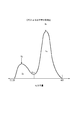
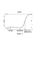
ここで、図5に示すように、メインピーク(MA)とサブピーク(MB)の間には極小値(MMin)が存在する。そして、分子量4000から極小値(MMin)までの分子量分布曲線の面積をSAとし、極小値(MMin)から分子量500万までの分子量分布曲線の面積をSBとする。
Here, as shown in FIG. 5, there is a minimum value (M Min ) between the main peak (M A ) and the sub peak (M B ). The area of the molecular weight distribution curve from the molecular weight 4000 to the minimum value (M Min ) is S A, and the area of the molecular weight distribution curve from the minimum value (M Min ) to the molecular weight 5 million is S B.
本発明において、メインピークの分子量(MA)を4000以上10000以下と低い領域で制御することにより低温定着をより高度に達成することができる。メインピークの分子量(MA)が10000を超えると低温定着性に劣り、4000未満にすると保存安定性に劣る傾向にある。また、サブピークの分子量を(MB)100000以上500000以下とすることにより、優れた耐オフセット性を維持することができる。100000未満であると高温オフセットが発生しやすく、500000を超えると定着阻害を発生しやすい傾向にある。このとき、メインピークの面積(SA)とサブピークの面積(SB)を合計した総面積に対する、メインピークの面積の比率(SA/(SA+SB))が、70%以上であると、低温定着と耐オフセット性が両立できるため、好ましい。70%を下回ると、低温定着に寄与する分子量5000以上10000以下の成分が少なくなる傾向にある。
In the present invention, the low temperature fixing can be achieved to a higher degree by controlling the molecular weight (M A ) of the main peak in a low region of 4000 or more and 10,000 or less. When the molecular weight (M A ) of the main peak exceeds 10,000, the low-temperature fixability tends to be poor, and when it is less than 4000, the storage stability tends to be poor. Further, by setting the molecular weight of the sub-peak to (M B ) 100,000 or more and 500,000 or less, excellent offset resistance can be maintained. When it is less than 100,000, high temperature offset tends to occur, and when it exceeds 500,000, fixing inhibition tends to occur. At this time, the ratio of the area of the main peak (S A / (S A + S B )) to the total area obtained by adding the area of the main peak (S A ) and the area of the sub peak (S B ) is 70% or more. And low temperature fixing and offset resistance can be achieved. If it is less than 70%, the component having a molecular weight of 5000 or more and 10,000 or less that contributes to low-temperature fixing tends to decrease.
なお、上記分子量分布は、低分子量重合体と、高分子量重合体を併用することで調整することができる。ここで、「低分子量重合体」とは、ピーク分子量が、4000~10000程度のものを意味する。一方、「高分子量重合体」とは、ピーク分子量が、10万~50万程度のものを意味する。
The molecular weight distribution can be adjusted by using a low molecular weight polymer and a high molecular weight polymer in combination. Here, the “low molecular weight polymer” means a polymer having a peak molecular weight of about 4000 to 10,000. On the other hand, “high molecular weight polymer” means one having a peak molecular weight of about 100,000 to 500,000.
本発明における磁性トナーの結着樹脂としては、スチレン系樹脂、ポリエステル系樹脂、エポキシ樹脂、および、ポリウレタン樹脂などが挙げられるが、特に限定されず従来公知の樹脂を用いることができる。中でも磁性体や離型剤などの分散性の観点で、スチレン系樹脂を主成分とすることが好ましい。なお、結着樹脂の主成分とは、本発明においては、結着樹脂中の少なくとも50質量%以上と定義する。
Examples of the binder resin of the magnetic toner in the present invention include styrene resins, polyester resins, epoxy resins, polyurethane resins, and the like, but are not particularly limited, and conventionally known resins can be used. Among these, from the viewpoint of dispersibility of a magnetic material or a release agent, it is preferable that a styrene resin is a main component. The main component of the binder resin is defined as at least 50% by mass or more in the binder resin in the present invention.
好ましく用いることのできるスチレン系樹脂としては、具体的にスチレン-プロピレン共重合体、スチレン-ビニルトルエン共重合体、スチレン-ビニルナフタリン共重合体、スチレン-アクリル酸メチル共重合体、スチレン-アクリル酸エチル共重合体、スチレン-アクリル酸ブチル共重合体、スチレン-アクリル酸オクチル共重合体、スチレン-アクリル酸ジメチルアミノエチル共重合体、スチレン-メタクリル酸メチル共重合体、スチレン-メタクリル酸エチル共重合体、スチレン-メタクリル酸ブチル共重合体、スチレン-メタクリル酸ジメチルアミノエチル共重合体、スチレン-ビニルメチルエーテル共重合体、スチレン-ビニルエチルエーテル共重合体、スチレン-ビニルメチルケトン共重合体、スチレン-ブタジエン共重合体、スチレン-イソプレン共重合体、スチレン-マレイン酸共重合体、スチレン-マレイン酸エステル共重合体などが挙げられる。これらは単独でまたは複数種を組み合わせて用いることができる。
Specific examples of styrenic resins that can be preferably used include styrene-propylene copolymers, styrene-vinyltoluene copolymers, styrene-vinylnaphthalene copolymers, styrene-methyl acrylate copolymers, and styrene-acrylic acids. Ethyl copolymer, styrene-butyl acrylate copolymer, styrene-octyl acrylate copolymer, styrene-dimethylaminoethyl acrylate copolymer, styrene-methyl methacrylate copolymer, styrene-ethyl methacrylate copolymer Polymer, styrene-butyl methacrylate copolymer, styrene-dimethylaminoethyl methacrylate copolymer, styrene-vinyl methyl ether copolymer, styrene-vinyl ethyl ether copolymer, styrene-vinyl methyl ketone copolymer, styrene -Butadiene copolymer , Styrene - isoprene copolymer, styrene - maleic acid copolymer, styrene - like maleic acid ester copolymer. These can be used alone or in combination of two or more.
本発明の磁性トナーのガラス転移温度(Tg)は47℃以上57℃以下であることが好ましい。ガラス転移温度が47℃以上57℃以下であると、良好な定着性を維持しつつ保存安定性、そして耐久現像性を向上できるために好ましい。
The glass transition temperature (Tg) of the magnetic toner of the present invention is preferably 47 ° C. or higher and 57 ° C. or lower. A glass transition temperature of 47 ° C. or more and 57 ° C. or less is preferred because storage stability and durability developability can be improved while maintaining good fixability.
また樹脂または磁性トナーのガラス転移温度は、示差走査熱量計、例えばパーキンエルマー社製のDSC-7やTAインスツルメンツジャパン社製のDSC2920を用いて、ASTM D3418-82に準じて測定することができる。
The glass transition temperature of the resin or magnetic toner can be measured according to ASTM D3418-82 using a differential scanning calorimeter such as DSC-7 manufactured by PerkinElmer or DSC2920 manufactured by TA Instruments Japan.
本発明の磁性トナーは、低温定着性の観点から、離型剤としてエステル化合物を含有し、磁性トナーが、示差走査熱量計(DSC)による測定において50℃以上80℃以下に最大吸熱ピークを有することが好ましい。
The magnetic toner of the present invention contains an ester compound as a release agent from the viewpoint of low-temperature fixability, and the magnetic toner has a maximum endothermic peak at 50 ° C. or more and 80 ° C. or less as measured by a differential scanning calorimeter (DSC). It is preferable.
エステル化合物としては、ベヘン酸ベヘニル、パルミチン酸パルミチル、ステアリン酸ステアリル、リグノセリン酸リグノセリル、グリセリントリベヘネート、カルナウバワックスなどの飽和脂肪酸モノエステル類が挙げられる。
Examples of the ester compound include saturated fatty acid monoesters such as behenyl behenate, palmityl palmitate, stearyl stearate, lignoceryl lignocerate, glyceryl tribehenate, carnauba wax and the like.
より好ましいエステル化合物は、炭素数が36以上48以下の1官能エステル化合物である。
More preferable ester compounds are monofunctional ester compounds having 36 to 48 carbon atoms.
また、エステル化合物として、前述の1官能エステル化合物の他、2官能エステル化合物をはじめ、4官能や6官能などの多官能エステル化合物を用いることもできる。具体的には、
セバシン酸ジベヘニル、ドデカン二酸ジステアリル、オクタデカン二酸ジステアリルなどの飽和脂肪族ジカルボン酸と飽和脂肪族アルコールとのジエステル化物;
ノナンジオールジベヘネート、ドデカンジオールジステアレートなどの飽和脂肪族ジオールと飽和脂肪酸とのジエステル化物;グリセリントリベヘネート、グリセリントリステアレートなどのトリアルコール類と飽和脂肪酸のトリエステル化物;
グリセリンモノベヘネート、グリセリンジベヘネートなどのトリアルコール類と飽和脂肪酸との部分エステル化物;
などが挙げられる。 In addition to the monofunctional ester compound described above, a bifunctional ester compound such as a tetrafunctional or hexafunctional polyfunctional ester compound can also be used as the ester compound. In particular,
Diesterified products of saturated aliphatic dicarboxylic acids and saturated aliphatic alcohols such as dibehenyl sebacate, distearyl dodecanedioate and distearyl octadecanedioate;
Diesterified products of saturated aliphatic diols such as nonanediol dibehenate and dodecanediol distearate and saturated fatty acids; triesterified products of trialcohols such as glycerol tribehenate and glycerol tristearate and saturated fatty acids;
Partially esterified products of trialcohols such as glycerin monobehenate and glycerin dibehenate and saturated fatty acids;
Etc.
ただし、このような多官能エステル化合物の場合には、後述する熱風による表面改質工程を実施する場合には、磁性トナー表面に染み出しやすい場合があり、その結果、均一帯電性や耐久現像性が低下しやすくなる傾向にある。
However, in the case of such a polyfunctional ester compound, when the surface modification step using hot air described later is performed, the magnetic toner surface may be easily oozed out. As a result, uniform chargeability and durable developability Tends to decrease.
その他、本発明において、用いることができる離型剤としては、具体的には、
パラフィンワックス、マイクロクリスタリンワックス、ペトロラタムなどの石油系ワックスおよびその誘導体;
モンタンワックスおよびその誘導体;
フィッシャートロプシュ法による炭化水素ワックスおよびその誘導体;
ポリエチレン、ポリプロピレンに代表されるポリオレフィンワックスおよびその誘導体;
カルナバワックス、キャンデリラワックスなど天然ワックスおよびその誘導体;
エステルワックス
などが挙げられる。ここで、誘導体とは酸化物や、ビニル系モノマーとのブロック共重合物、グラフト変性物を含む。 In addition, as the release agent that can be used in the present invention, specifically,
Petroleum waxes such as paraffin wax, microcrystalline wax, petrolatum and derivatives thereof;
Montan wax and its derivatives;
Hydrocarbon wax and its derivatives by Fischer-Tropsch process;
Polyolefin waxes typified by polyethylene and polypropylene and derivatives thereof;
Natural waxes such as carnauba wax and candelilla wax and their derivatives;
Examples include ester wax. Here, the derivatives include oxides, block copolymers with vinyl monomers, and graft modified products.
これらの離型剤は、単独または二種以上組み合わせて用いることが可能である。
These mold release agents can be used alone or in combination of two or more.
本発明の磁性トナーに離型剤を用いる場合、結着樹脂100質量部に対し離型剤を0.5質量部以上10質量部以下用いることが好ましい。0.5質量部以上10質量部以下であると、低温定着性が向上するとともに、磁性トナーの保存安定性を損なわないため好ましい。
When a release agent is used for the magnetic toner of the present invention, it is preferable to use 0.5 to 10 parts by weight of the release agent with respect to 100 parts by weight of the binder resin. The content of 0.5 parts by mass or more and 10 parts by mass or less is preferable because the low-temperature fixability is improved and the storage stability of the magnetic toner is not impaired.
また、これらの離型剤は、樹脂製造時、樹脂を溶剤に溶解し、樹脂溶液温度を上げ、撹拌しながら添加混合する方法や、磁性トナー製造中の溶融混練時に添加する方法などにより結着樹脂に含有させることができる。
In addition, these release agents are bound by, for example, a method of dissolving a resin in a solvent at the time of resin production, increasing the temperature of the resin solution, adding and mixing with stirring, or a method of adding at the time of melt kneading during magnetic toner production. It can be contained in the resin.
磁性トナーが、示差走査熱量計(DSC)による測定において50℃以上80℃以下に最大吸熱ピークを有するように制御しやすい点で、離型剤の最大吸熱ピーク温度は50℃以上80℃以下であることが好ましい。
The maximum endothermic peak temperature of the release agent is 50 ° C. or more and 80 ° C. or less because the magnetic toner can be easily controlled so as to have a maximum endothermic peak at 50 ° C. or more and 80 ° C. or less as measured by a differential scanning calorimeter (DSC). Preferably there is.
本発明においては、磁性トナーが50℃以上80℃以下に最大吸熱ピークを有することで、定着時に磁性トナーが可塑化しやすく、低温定着性が良化する。また、耐久現像性も維持されやすいと同時に、長期間保存しても離型剤の染み出しなども生じにくく好ましい。
In the present invention, since the magnetic toner has a maximum endothermic peak at 50 ° C. or more and 80 ° C. or less, the magnetic toner is easily plasticized at the time of fixing, and the low-temperature fixability is improved. Further, it is preferable that the durable developability is easily maintained, and that the release agent oozes out even if stored for a long period of time.
磁性トナーが50℃以上75℃以下に最大吸熱ピークを有することがより好ましい。
More preferably, the magnetic toner has a maximum endothermic peak at 50 ° C. or higher and 75 ° C. or lower.
本発明において、最大吸熱ピークのピークトップ温度の測定は、示差走査熱量分析装置「Q1000」(TA Instruments社製)を用いてASTM D3418-82に準じて測定する。装置検出部の温度補正はインジウムと亜鉛の融点を用い、熱量の補正についてはインジウムの融解熱を用いる。
In the present invention, the peak top temperature of the maximum endothermic peak is measured according to ASTM D3418-82 using a differential scanning calorimeter “Q1000” (manufactured by TA Instruments). The temperature correction of the device detection unit uses the melting points of indium and zinc, and the correction of heat uses the heat of fusion of indium.
具体的には、磁性トナー約10mgを精秤し、これをアルミニウム製のパンの中に入れ、リファレンスとして空のアルミニウム製のパンを用い、測定温度範囲30~200℃の間で、昇温速度10℃/分で測定を行う。なお、測定においては、一度200℃まで昇温させ、続いて30℃まで降温し、その後に再度昇温を行う。この2度目の昇温過程での温度30~200℃の範囲におけるDSC曲線から磁性トナーの最大吸熱ピークのピークトップ温度を求める。
Specifically, about 10 mg of magnetic toner is precisely weighed, put in an aluminum pan, and an empty aluminum pan is used as a reference. The measurement is performed at 10 ° C / min. In the measurement, the temperature is once raised to 200 ° C., subsequently lowered to 30 ° C., and then the temperature is raised again. The peak top temperature of the maximum endothermic peak of the magnetic toner is obtained from the DSC curve in the temperature range of 30 to 200 ° C. in the second temperature raising process.
本発明において、磁性トナーに含まれる磁性体としては、
マグネタイト、マグヘマイトもしくはフェライトなどの酸化鉄、
鉄、コバルトもしくはニッケルのような金属、
またはこれらの金属とアルミニウム、銅、マグネシウム、スズ、亜鉛、ベリリウム、カルシウム、マンガン、セレン、チタン、タングステンもしくはバナジウムのような金属との合金、
または、それらの混合物などが挙げられる。 In the present invention, as the magnetic material contained in the magnetic toner,
Iron oxides such as magnetite, maghemite or ferrite,
Metals such as iron, cobalt or nickel,
Or alloys of these metals with metals such as aluminum, copper, magnesium, tin, zinc, beryllium, calcium, manganese, selenium, titanium, tungsten or vanadium,
Or a mixture thereof may be used.
上記磁性体は一次粒子の個数平均粒径(D1)が0.50μm以下であることが好ましく、より好ましくは0.05μm~0.30μmである。
The number average particle size (D1) of the primary particles of the magnetic material is preferably 0.50 μm or less, and more preferably 0.05 μm to 0.30 μm.
また、本発明において好ましい磁性トナーの磁気特性に制御しやすい点で、磁性体の磁場79.6kA/mにおいて、以下のような磁気特性に制御することが好ましい。
In addition, it is preferable to control to the following magnetic characteristics at a magnetic field of 79.6 kA / m from the viewpoint of easy control to the magnetic characteristics of the preferred magnetic toner in the present invention.
すなわち、飽和磁化(σs)が40~80Am2/kg(より好ましくは50~70Am2/kg)であり、残留磁化(σr)が1.5~6.5Am2/kg、より好ましくは2.0~5.5Am2/kgであることが好ましい。
That is, the saturation magnetization (σs) is 40 to 80 Am 2 / kg (more preferably 50 to 70 Am 2 / kg), and the residual magnetization (σr) is 1.5 to 6.5 Am 2 / kg, more preferably 2. It is preferably 0 to 5.5 Am 2 / kg.
本発明の磁性トナーは、磁性体を35質量%以上50質量%以下含有することが好ましく、40質量%以上50質量%以下含有することがより好ましい。磁性トナーにおける磁性体の含有量が35質量%未満の場合には、現像スリーブ内のマグネットロールとの磁気引力が低下し、カブリが悪化する傾向にある。一方、磁性体の含有量が50質量%を超える場合には、現像性が低下することにより、濃度が低下する場合がある。
The magnetic toner of the present invention preferably contains 35% by mass or more and 50% by mass or less, more preferably 40% by mass or more and 50% by mass or less of the magnetic material. When the content of the magnetic substance in the magnetic toner is less than 35% by mass, the magnetic attraction with the magnet roll in the developing sleeve tends to decrease and fog tends to deteriorate. On the other hand, when the content of the magnetic material exceeds 50% by mass, the density may decrease due to the decrease in developability.
なお、磁性トナー中の磁性体の含有量は、パーキンエルマー社製熱分析装置TGA Q5000IRなどを用いて測定することができる。測定方法は、窒素雰囲気下において昇温速度25℃/分で常温から900℃まで磁性トナーを加熱し、100~750℃の減量質量を磁性トナーから磁性体を除いた成分の質量とし、残存質量を磁性体量とする。
The content of the magnetic substance in the magnetic toner can be measured by using a thermal analyzer TGA Q5000IR manufactured by PerkinElmer. In the measurement method, the magnetic toner is heated from room temperature to 900 ° C. at a temperature rising rate of 25 ° C./min in a nitrogen atmosphere, and the weight loss of 100 to 750 ° C. is the mass of the component excluding the magnetic material from the magnetic toner, and the remaining mass. Is the amount of magnetic material.
本発明の磁性トナーは、磁場79.6kA/mにおける、飽和磁化(σs)が30.0Am2/kg以上40.0Am2/kg以下であることが好ましく、32.0Am2/kg以上38.0Am2/kg以下であることがより好ましい。また、残留磁化(σr)の飽和磁化(σs)に対する比[σr/σs]が0.03以上0.10以下であることが好ましく、0.03以上0.06以下であることがより好ましい。
The magnetic toner of the present invention preferably has a saturation magnetization (σs) of 30.0 Am 2 / kg or more and 40.0 Am 2 / kg or less at a magnetic field of 79.6 kA / m, 32.0 Am 2 / kg or more and 38.38 or more. More preferably, it is 0 Am 2 / kg or less. Further, the ratio [σr / σs] of the residual magnetization (σr) to the saturation magnetization (σs) is preferably 0.03 or more and 0.10 or less, and more preferably 0.03 or more and 0.06 or less.
飽和磁化(σs)は、磁性体の粒径や形状、添加元素などにより制御できる。
Saturation magnetization (σs) can be controlled by the particle size and shape of the magnetic material, additive elements, and the like.
また、好ましくは、残留磁化(σr)が3.0Am2/kg以下、より好ましくは、2.6Am2/kg以下、さらに好ましくは、2.4Am2/kg以下である。
Also, preferably, the residual magnetization (.sigma.r) is 3.0Am 2 / kg or less, more preferably, 2.6Am 2 / kg or less, still more preferably not more than 2.4Am 2 / kg.
σr/σsが小さいということは、磁性トナーの残留磁化が小さいことを意味する。
A small σr / σs means that the residual magnetization of the magnetic toner is small.
ここで、磁性一成分現像方式においては、現像スリーブ内部に存在する多極のマグネットの影響で磁性トナーは現像スリーブに取り込まれたり、吐き出されたりする。吐き出された磁性トナー(現像スリーブから離れた磁性トナー)はσr/σsが小さいと磁気凝集しにくい。このような磁性トナーが再び取り込み極で現像スリーブに付着し、ブレードニップ部に突入すると磁気凝集が少ない状態であるため、ブレードニップ部での磁性トナーの入れ替わりが効率良く行われ、迅速に帯電が立ち上がりやすい。
Here, in the magnetic one-component development system, the magnetic toner is taken into or discharged from the developing sleeve due to the influence of a multipolar magnet existing inside the developing sleeve. The discharged magnetic toner (magnetic toner separated from the developing sleeve) is less likely to be magnetically aggregated when σr / σs is small. When such magnetic toner adheres to the developing sleeve again at the take-in pole and enters the blade nip, there is little magnetic aggregation, so the magnetic toner is efficiently replaced at the blade nip and charged quickly. Easy to get up.
なお、[σr/σs]は、磁性トナーが含有する磁性体の粒径、形状、および、磁性体を製造する際に添加する添加剤を調整することで、上記範囲に調整することが可能である。具体的には、磁性体にシリカやリンなどを添加することによってσsを高く保ったまま、σrをより低くすることが可能となる。また、磁性体の表面積が小さいほどσrは小さくなり、形状は八面体よりも磁気異方性が小さな球形の方がσrは小さくなる。これらを組み合わせることにより、σrを非常に低くすることが可能となり、σr/σsを0.10以下に制御することができる。
[Σr / σs] can be adjusted to the above range by adjusting the particle size and shape of the magnetic material contained in the magnetic toner and the additive added when the magnetic material is produced. is there. Specifically, by adding silica, phosphorus, or the like to the magnetic material, it is possible to lower σr while keeping σs high. Also, the smaller the surface area of the magnetic material, the smaller the σr, and the smaller the shape, the smaller the σr, the smaller the magnetic anisotropy than the octahedron. By combining these, σr can be made very low, and σr / σs can be controlled to 0.10 or less.
本発明において磁性トナー、および、磁性体の磁化の強さ(σs)および残留磁化(σr)は、振動型磁力計VSM P-1-10(東英工業社製)を用いて、25℃の室温にて外部磁場79.6kA/mで測定する。外部磁場が79.6kA/mにて測定する理由については以下のとおりである。一般的に、現像スリーブ中に固定されているマグネットローラーの現像極の磁力は79.6kA/m(1000エルステッド)前後である。このため、外部磁場79.6kA/mで残留磁化を測定することにより現像領域での磁性トナー挙動を捉えることができるからである。
In the present invention, the magnetic toner and the magnetization intensity (σs) and residual magnetization (σr) of the magnetic material are 25 ° C. using a vibration magnetometer VSM P-1-10 (manufactured by Toei Kogyo Co., Ltd.). Measure at an external magnetic field of 79.6 kA / m at room temperature. The reason why the external magnetic field is measured at 79.6 kA / m is as follows. Generally, the magnetic force of the developing pole of the magnet roller fixed in the developing sleeve is around 79.6 kA / m (1000 oersted). For this reason, the magnetic toner behavior in the development region can be captured by measuring the residual magnetization with an external magnetic field of 79.6 kA / m.
本発明の磁性トナーにおいては、荷電制御剤を添加することが好ましい。なお、本発明においては、結着樹脂自体は負帯電性が高いので、負帯電性トナーであることが好ましい。
In the magnetic toner of the present invention, it is preferable to add a charge control agent. In the present invention, since the binder resin itself has a high negative chargeability, it is preferably a negatively chargeable toner.
負帯電用の荷電制御剤としては、例えば、有機金属錯化合物、キレート化合物が有効で、その例としては、モノアゾ金属錯化合物;アセチルアセトン金属錯化合物;芳香族ハイドロキシカルボン酸または芳香族ダイカルボン酸の金属錯化合物などが挙げられる。
As the charge control agent for negative charging, for example, organometallic complex compounds and chelate compounds are effective. Examples thereof include monoazo metal complex compounds; acetylacetone metal complex compounds; aromatic hydroxycarboxylic acids or aromatic dicarboxylic acids. Examples thereof include metal complex compounds.
負帯電用の荷電制御剤としては、例えばSpilon Black TRH、T-77、T-95(保土谷化学社)、BONTRON(登録商標)S-34、S-44、S-54、E-84、E-88、E-89(オリエント化学社)が挙げられる。
Examples of the charge control agent for negative charging include Spiron Black TRH, T-77, T-95 (Hodogaya Chemical Co., Ltd.), BONTRON (registered trademark) S-34, S-44, S-54, E-84, And E-88 and E-89 (Orient Chemical Co., Ltd.).
これらの荷電制御剤は単独または二種以上組み合わせて用いることが可能である。これらの荷電制御剤の使用量は、磁性トナーの帯電量の点から、結着樹脂100質量部あたり好ましくは0.1~10.0質量部、より好ましくは0.1~5.0質量部である。
These charge control agents can be used alone or in combination of two or more. The amount of these charge control agents used is preferably 0.1 to 10.0 parts by weight, more preferably 0.1 to 5.0 parts by weight per 100 parts by weight of the binder resin, from the viewpoint of the charge amount of the magnetic toner. It is.
磁性トナー粒子表面に固着させる無機微粒子としては、シリカ微粒子、チタニア微粒子、アルミナ微粒子から選択される少なくとも1種が好ましい。このような無機微粒子は、流動性向上効果や硬度の観点で類似しているため、磁性トナー粒子表面の固着状態の制御により、均一帯電性が得られやすい。また、磁性トナーに含有される無機微粒子の総量に対して、85%以上がシリカ微粒子であることが好ましい。これは、上記無機微粒子の中でも、シリカ微粒子が最も帯電特性に優れ、本発明の効果を発揮しやすいためである。
The inorganic fine particles to be fixed to the magnetic toner particle surface are preferably at least one selected from silica fine particles, titania fine particles, and alumina fine particles. Since such inorganic fine particles are similar in terms of fluidity improvement effect and hardness, uniform chargeability is easily obtained by controlling the fixing state of the magnetic toner particle surface. In addition, it is preferable that 85% or more of the fine particles of silica are contained in the total amount of inorganic fine particles contained in the magnetic toner. This is because, among the inorganic fine particles, silica fine particles are most excellent in charging characteristics and easily exert the effects of the present invention.
本発明の磁性トナーには、前記のように固着強度を制御した無機微粒子だけでなく、他の有機または無機微粒子を添加してもよい。例えば、
シリカ微粒子、フッ素樹脂粒子、ステアリン酸亜鉛粒子、ポリフッ化ビニリデン粒子のような滑剤;
酸化セリウム粒子、炭化ケイ素粒子、アルカリ土類金属のチタン酸塩の微粒子;
具体的にはチタン酸ストロンチウム微粒子、チタン酸バリウム微粒子、チタン酸カルシウム微粒子などの研磨剤
などが挙げられる。また、シリカなどのスペーサー粒子を本発明の効果に影響を与えない程度に少量用いることもできる。中でも、シリカ微粒子は流動性を著しく良化させ、本発明の効果を発揮しやすいため、好ましい。 The magnetic toner of the present invention may contain not only the inorganic fine particles whose adhesion strength is controlled as described above, but also other organic or inorganic fine particles. For example,
Lubricants such as silica fine particles, fluororesin particles, zinc stearate particles, polyvinylidene fluoride particles;
Fine particles of cerium oxide particles, silicon carbide particles, alkaline earth metal titanates;
Specific examples include abrasives such as strontium titanate fine particles, barium titanate fine particles, and calcium titanate fine particles. Further, a small amount of spacer particles such as silica can be used so as not to affect the effect of the present invention. Among these, silica fine particles are preferable because they remarkably improve fluidity and easily exert the effects of the present invention.
固着強度を制御した無機微粒子は、磁性トナーに良好な流動性を付与させるために、窒素吸着によるBET法で測定した比表面積(BET比表面積)が20m2/g以上350m2/g以下のものが好ましい。より好ましくは25m2/g以上300m2/g以下である。
Inorganic fine particles with controlled adhesion strength have a specific surface area (BET specific surface area) measured by the BET method by nitrogen adsorption of 20 m 2 / g or more and 350 m 2 / g or less in order to impart good fluidity to the magnetic toner. Is preferred. More preferably not more than 25 m 2 / g or more 300m 2 / g.
上記窒素吸着によるBET法で測定した比表面積(BET比表面積)の測定は、JISZ8830(2001年)に準じて行う。測定装置としては、定容法によるガス吸着法を測定方式として採用している「自動比表面積・細孔分布測定装置 TriStar3000(島津製作所社製)」を用いる。
The measurement of the specific surface area (BET specific surface area) measured by the BET method by nitrogen adsorption is performed according to JISZ8830 (2001). As the measuring apparatus, an “automatic specific surface area / pore distribution measuring apparatus, TriStar 3000 (manufactured by Shimadzu Corporation)” which employs a gas adsorption method based on a constant volume method as a measuring method is used.
固着強度を制御した無機微粒子は、疎水化処理を施したものであることが好ましく、メタノール滴定試験によって測定された疎水化度が40%以上、より好ましくは50%以上となるように疎水化処理したものが特に好ましい。
It is preferable that the inorganic fine particles having a controlled fixing strength are subjected to a hydrophobization treatment, and the hydrophobization treatment is performed so that the degree of hydrophobization measured by a methanol titration test is 40% or more, more preferably 50% or more. That is particularly preferred.
上記疎水化処理の方法としては、有機ケイ素化合物、シリコーンオイルまたは長鎖脂肪酸などで処理する方法が挙げられる。
Examples of the hydrophobic treatment method include a treatment with an organosilicon compound, silicone oil, long-chain fatty acid, or the like.
上記有機ケイ素化合物としては、例えばヘキサメチルジシラザン、トリメチルシラン、トリメチルエトキシシラン、イソブチルトリメトキシシラン、トリメチルクロロシラン、ジメチルジクロロシラン、メチルトリクロロシラン、ジメチルエトキシシラン、ジメチルジメトキシシラン、ジフェニルジエトキシシラン、ヘキサメチルジシロキサンなどが挙げられる。これらは一種または二種以上の混合物で用いられる。
Examples of the organosilicon compound include hexamethyldisilazane, trimethylsilane, trimethylethoxysilane, isobutyltrimethoxysilane, trimethylchlorosilane, dimethyldichlorosilane, methyltrichlorosilane, dimethylethoxysilane, dimethyldimethoxysilane, diphenyldiethoxysilane, hexa And methyldisiloxane. These are used in one kind or a mixture of two or more kinds.
上記シリコーンオイルとしては、例えばジメチルシリコーンオイル、メチルフェニルシリコーンオイル、α-メチルスチレン変性シリコーンオイル、クロルフェニルシリコーンオイルまたはフッ素変性シリコーンオイルなどが挙げられる。
Examples of the silicone oil include dimethyl silicone oil, methylphenyl silicone oil, α-methylstyrene modified silicone oil, chlorophenyl silicone oil, and fluorine modified silicone oil.
上記長鎖脂肪酸は炭素数が10~22の脂肪酸を好適に用いることができ、直鎖脂肪酸であっても、分岐脂肪酸であってもよい。また、飽和脂肪酸、不飽和脂肪酸のいずれも用いることが可能である。
The long-chain fatty acid may be a fatty acid having 10 to 22 carbon atoms, and may be a linear fatty acid or a branched fatty acid. Further, either saturated fatty acid or unsaturated fatty acid can be used.
この中で、炭素数が10~22の直鎖の飽和脂肪酸は無機微粒子の表面を均一に処理しやすく、非常に好ましい。
Among these, straight-chain saturated fatty acids having 10 to 22 carbon atoms are very preferable because they can easily treat the surface of the inorganic fine particles uniformly.
直鎖の飽和脂肪酸としては、例えばカプリン酸、ラウリン酸、ミルスチン酸、パルミチン酸、ステアリン酸、アラキジン酸、ベヘン酸などが挙げられる。
Examples of the linear saturated fatty acid include capric acid, lauric acid, myristic acid, palmitic acid, stearic acid, arachidic acid, and behenic acid.
本発明に用いられる無機微粒子の中でも、シリカ微粒子をシリコーンオイルにより処理したものが好ましい。より好ましくは、シリカ微粒子をケイ素化合物とシリコーンオイルにより処理したものであり、疎水化度を好適に制御できる。
Among the inorganic fine particles used in the present invention, those obtained by treating silica fine particles with silicone oil are preferable. More preferably, silica fine particles are treated with a silicon compound and silicone oil, and the degree of hydrophobicity can be suitably controlled.
シリカ微粒子をシリコーンオイルで処理する方法としては、例えば、ケイ素化合物で処理された無機微粒子とシリコーンオイルとをヘンシェルミキサーなどの混合機を用いて直接混合する方法や、無機微粒子にシリコーンオイルを噴霧する方法が挙げられる。あるいは、適当な溶剤にシリコーンオイルを溶解または分散させた後、無機微粒子を加えて混合し、溶剤を除去する方法でもよい。
As a method of treating silica fine particles with silicone oil, for example, a method of directly mixing inorganic fine particles treated with a silicon compound and silicone oil using a mixer such as a Henschel mixer, or spraying silicone oil onto inorganic fine particles A method is mentioned. Alternatively, after dissolving or dispersing silicone oil in a suitable solvent, inorganic fine particles may be added and mixed to remove the solvent.
シリコーンオイルの処理量は、良好な疎水性を得るために、シリカ微粒子100質量部に対し1質量部以上40質量部以下であることが好ましく、3質量部以上35質量部以下であることがより好ましい。
In order to obtain good hydrophobicity, the treatment amount of the silicone oil is preferably 1 part by mass or more and 40 parts by mass or less, more preferably 3 parts by mass or more and 35 parts by mass or less with respect to 100 parts by mass of the silica fine particles. preferable.
本発明の磁性トナーは、現像性や定着性のバランスの観点から、重量平均粒径(D4)が、7.0μm以上12.0μm以下であることが好ましい。より好ましくは7.5μm以上11.0μm以下、さらに好ましくは、7.5μm以上10.0μm以下である。
The magnetic toner of the present invention preferably has a weight average particle diameter (D4) of 7.0 μm or more and 12.0 μm or less from the viewpoint of a balance between developability and fixability. More preferably, they are 7.5 micrometers or more and 11.0 micrometers or less, More preferably, they are 7.5 micrometers or more and 10.0 micrometers or less.
また、本発明の磁性トナーは、平均円形度が0.955以上、より好ましくは、0.957以上であることが好ましい。
Further, the magnetic toner of the present invention preferably has an average circularity of 0.955 or more, more preferably 0.957 or more.
以下に、本発明の磁性トナーの製造方法について例示するが、これに限定されるわけではない。
Hereinafter, the method for producing the magnetic toner of the present invention will be exemplified, but the present invention is not limited thereto.
本発明の磁性トナーは、無機微粒子の固着状態を調整することができ、好ましくは平均円形度を調整する工程を有する製造方法であれば、特に限定されず、公知の方法によって製造することができる。
The magnetic toner of the present invention is not particularly limited as long as it is a production method that can adjust the fixing state of inorganic fine particles, and preferably has a step of adjusting the average circularity, and can be produced by a known method. .
そのような製造方法としては、以下の方法を好適に例示できる。まず、結着樹脂および磁性体、ならびに、必要に応じて、離型剤および荷電制御剤などのその他の材料を、ヘンシェルミキサーまたはボールミルのような混合機により十分混合する。その後、ロール、ニーダーおよびエクストルーダーのような熱混練機を用いて溶融、捏和および混練して樹脂類を互いに相溶せしめる。
As such a production method, the following method can be preferably exemplified. First, the binder resin and the magnetic material, and, if necessary, other materials such as a release agent and a charge control agent are sufficiently mixed by a mixer such as a Henschel mixer or a ball mill. Thereafter, the resin is mutually melted by melting, kneading and kneading using a heat kneader such as a roll, a kneader and an extruder.
得られた溶融混練物を冷却固化後に粗粉砕、微粉砕、分級を行い、得られた磁性トナー粒子に、無機微粒子などの外添剤を外添混合することによって、磁性トナーを得ることができる。
The obtained melt-kneaded product is cooled and solidified, then coarsely pulverized, finely pulverized and classified, and external magnetic additives such as inorganic fine particles are externally added to the obtained magnetic toner particles to obtain a magnetic toner. .
上記混合機としては、ヘンシェルミキサー(三井鉱山社製);スーパーミキサー(カワタ社製);リボコーン(大川原製作所社製);ナウターミキサー、タービュライザー、サイクロミックス(ホソカワミクロン社製);スパイラルピンミキサー(太平洋機工社製);レーディゲミキサー(マツボー社製)などが挙げられる。
As the above mixer, Henschel mixer (made by Mitsui Mining Co., Ltd.); Super mixer (made by Kawata Co., Ltd.); Ribocorn (made by Okawara Seisakusho Co., Ltd.); (Manufactured by Taiheiyo Kiko Co., Ltd.);
上記混練機としては、
KRCニーダー(栗本鉄工所社製);
ブス・コ・ニーダー(Buss社製);
TEM型押し出し機(東芝機械社製);
TEX二軸混練機(日本製鋼所社製);
PCM混練機(池貝鉄工所社製);
三本ロールミル、ミキシングロールミル、ニーダー(井上製作所社製);
ニーデックス(三井鉱山社製);
MS式加圧ニーダー、ニダールーダー(森山製作所社製);
バンバリーミキサー(神戸製鋼所社製)
などが挙げられる。 As the kneading machine,
KRC kneader (manufactured by Kurimoto Iron Works);
Bus co-kneader (Buss);
TEM type extruder (manufactured by Toshiba Machine);
TEX twin-screw kneader (Nippon Steel Works);
PCM kneader (manufactured by Ikekai Iron Works);
Triple roll mill, mixing roll mill, kneader (manufactured by Inoue Seisakusho);
Needex (Mitsui Mining Co., Ltd.);
MS type pressure kneader, nider ruder (Moriyama Seisakusho);
Banbury mixer (manufactured by Kobe Steel)
Etc.
上記粉砕機としては、カウンタージェットミル、ミクロンジェット、イノマイザ(ホソカワミクロン社製);IDS型ミル、PJMジェット粉砕機(日本ニューマチック工業社製);クロスジェットミル(栗本鉄工所社製);ウルマックス(日曹エンジニアリング社製);SKジェット・オー・ミル(セイシン企業社製);クリプトロン(川崎重工業社製);ターボミル(ターボ工業社製);スーパーローター(日清エンジニアリング)などが挙げられる。
Examples of the pulverizer include counter jet mill, micron jet, inomizer (manufactured by Hosokawa Micron Co.); IDS type mill, PJM jet pulverizer (manufactured by Nippon Pneumatic Industry Co., Ltd.); cross jet mill (manufactured by Kurimoto Iron Works Co., Ltd.); (Nisso Engineering Co., Ltd.); SK Jet O-Mill (Seishin Enterprise Co., Ltd.); Cryptron (Kawasaki Heavy Industries Co., Ltd.); Turbo Mill (Turbo Industry Co., Ltd.); Super Rotor (Nisshin Engineering Co., Ltd.) and the like.
このうち、ターボミルを使用し、微粉砕時の排気温度を調整することにより、平均円形度の制御が可能である。排気温度を低く(例えば40℃以下)すると、平均円形度の値が小さくなり、排気温度を高く(例えば50℃前後)すると、平均円形度の値が大きくなる。
Among these, it is possible to control the average circularity by using a turbo mill and adjusting the exhaust temperature at the time of fine pulverization. When the exhaust temperature is lowered (for example, 40 ° C. or lower), the value of the average circularity is decreased, and when the exhaust temperature is increased (for example, around 50 ° C.), the value of the average circularity is increased.
上記分級機としては、クラッシール、マイクロンクラッシファイアー、スペディッククラシファイアー(セイシン企業社製);ターボクラッシファイアー(日清エンジニアリング社製);ミクロンセパレータ、ターボプレックス(ATP)、TSPセパレータ(ホソカワミクロン社製);エルボージェット(日鉄鉱業社製)、ディスパージョンセパレータ(日本ニューマチック工業社製);YMマイクロカット(安川商事社製)などが挙げられる。
The classifiers include: Classy, Micron Classifier, Spedic Classifier (manufactured by Seishin Enterprise Co., Ltd.); Turbo Classifier (Nisshin Engineering Co., Ltd.); Micron Separator, Turboplex (ATP), TSP Separator (manufactured by Hosokawa Micron Co., Ltd.) ); Elbow Jet (manufactured by Nippon Steel & Mining Co., Ltd.), Dispersion Separator (manufactured by Nippon Pneumatic Industrial Co., Ltd.); YM Microcut (manufactured by Yaskawa Shoji Co., Ltd.) and the like.
粗粒などをふるい分けるために用いられる篩い装置としては、
ウルトラソニック(晃栄産業社製);
レゾナシーブ、ジャイロシフター(徳寿工作所社製);
バイブラソニックシステム(ダルトン社製);
ソニクリーン(新東工業社製);
ターボスクリーナー(ターボ工業社製);
ミクロシフター(槙野産業社製);
円形振動篩い
などが挙げられる。 As a sieving device used for sieving coarse particles,
Ultrasonic (Made by Sakae Sangyo);
Resona sieve, gyro shifter (manufactured by Deoksugaku Kosakusha);
Vibrasonic system (Dalton);
Sonic clean (manufactured by Shinto Kogyo);
Turbo screener (manufactured by Turbo Industry);
Micro shifter (manufactured by Hadano Sangyo Co., Ltd.);
A circular vibrating sieve is exemplified.
本発明に係る磁性トナーを作製するには、上述したような磁性トナー構成材料を混合機により十分混合した後、混練機を用いてよく混練し、冷却固化後粗粉砕を行った後に微粉砕、分級を行って磁性トナー粒子を得る。必要に応じて、分級工程後に表面改質装置を用いて、磁性トナー粒子の表面改質や平均円形度の調整を行って、最終的に磁性トナー粒子を得てもよい。
In order to produce the magnetic toner according to the present invention, the magnetic toner constituent materials as described above are sufficiently mixed by a mixer, then thoroughly kneaded using a kneader, cooled and solidified and then coarsely pulverized, Classification is performed to obtain magnetic toner particles. If necessary, the surface of the magnetic toner particles may be modified and the average circularity may be adjusted using a surface modification device after the classification step to finally obtain the magnetic toner particles.
磁性トナー粒子を得たのち、さらに無機微粒子を添加し、好ましくは後述する混合処理装置を用いて、外添混合処理することにより、本発明に係る磁性トナーを製造することができる。
The magnetic toner according to the present invention can be produced by obtaining the magnetic toner particles, further adding inorganic fine particles, and preferably performing external addition mixing processing using a mixing processing apparatus described later.
本発明において特に好ましい磁性トナーの製造工程としては、例えば瞬間的に磁性トナー粒子の表面に高温の熱風を吹きつけ、直後に冷風によって磁性トナー粒子を冷却することによって磁性トナー粒子の表面改質を行う熱風処理工程が挙げられる。
In the present invention, the magnetic toner is preferably produced by, for example, instantaneously blowing high-temperature hot air onto the surface of the magnetic toner particles and immediately cooling the magnetic toner particles with cold air to modify the surface of the magnetic toner particles. The hot-air processing process to perform is mentioned.
このような熱風処理工程によってトナー粒子の表面を改質することは、磁性トナー粒子に過度の熱を加えることがないので原材料成分の変質を防ぎつつ磁性トナー粒子の表面改質を行うことができるとともに、本発明において好ましい平均円形度に調整しやすい。
By modifying the surface of the toner particles by such a hot air treatment process, excessive heat is not applied to the magnetic toner particles, so that the surface modification of the magnetic toner particles can be performed while preventing deterioration of the raw material components. At the same time, it is easy to adjust the average circularity preferable in the present invention.
磁性トナー粒子の熱風処理工程には、例えば、図1に示すような表面改質装置を用いることができる。図1に示す表面改質装置において、トナー粒子(磁性トナー粒子)51はオートフィーダー52で供給ノズル53を通じて、一定量で表面改質装置内部54に供給される。表面改質装置内部54はブロワー59で吸引されているので、供給ノズル53から導入されたトナー粒子(磁性トナー粒子)51は機内に分散する。機内に分散にされた磁性トナー粒子51は、熱風導入口55から導入される熱風で、瞬間的に熱が加えられて表面改質される。ここでは、ヒーターにより熱風を発生させているが、磁性トナー粒子の表面改質に十分な熱風を発生させられるものであれば装置は特に限定されない。
In the hot air treatment process of the magnetic toner particles, for example, a surface modifying apparatus as shown in FIG. 1 can be used. In the surface modifying apparatus shown in FIG. 1, toner particles (magnetic toner particles) 51 are supplied to the inside of the surface modifying apparatus 54 by a fixed amount through a supply nozzle 53 by an auto feeder 52. Since the interior 54 of the surface modifying apparatus is sucked by the blower 59, the toner particles (magnetic toner particles) 51 introduced from the supply nozzle 53 are dispersed in the apparatus. The magnetic toner particles 51 dispersed in the machine are hot air introduced from the hot air introduction port 55, and heat is instantaneously applied to reform the surface. Here, hot air is generated by a heater, but the apparatus is not particularly limited as long as it can generate hot air sufficient for surface modification of magnetic toner particles.
熱風の温度は、好ましくは180~400℃であり、より好ましくは200~350℃である。熱風流量としては、好ましくは、4m3/分~10m3/分であり、より好ましくは、5m3/分~8m3/分である。
The temperature of the hot air is preferably 180 to 400 ° C, more preferably 200 to 350 ° C. The flow rate of hot air is preferably 4 m 3 / min to 10 m 3 / min, more preferably 5 m 3 / min to 8 m 3 / min.
また、冷風流量としては、好ましくは、2m3/分~6m3/分であり、より好ましくは、3m3/分~5m3/分である。
Further, the flow rate of the cold air is preferably 2 m 3 / min to 6 m 3 / min, more preferably 3 m 3 / min to 5 m 3 / min.
ブロア風量としては、好ましくは、10m3/分~30m3/分であり、より好ましくは、12m3/分~25m3/分である。
The blower air volume is preferably 10 m 3 / min to 30 m 3 / min, and more preferably 12 m 3 / min to 25 m 3 / min.
インジェクションエア流量は、好ましくは、0.2m3/分~3m3/分であり、より好ましくは、0.5m3/分~2m3/分である。
The injection air flow rate is preferably 0.2 m 3 / min to 3 m 3 / min, and more preferably 0.5 m 3 / min to 2 m 3 / min.
図1に示す表面改質装置において、表面改質されたトナー粒子(表面改質された磁性トナー粒子)57は、冷風導入口56から導入される冷風で瞬時に冷却される。本発明では冷風には液体窒素を用いているが、表面改質された磁性トナー粒子57を瞬時に冷却することができれば、手段は特に限定されない。冷風の温度は、好ましくは2~15℃であり、より好ましくは2~10℃である。表面改質された磁性トナー粒子57はブロワー59で吸引されて、サイクロン58で捕集される。
1, the surface-modified toner particles (surface-modified magnetic toner particles) 57 are instantaneously cooled by the cold air introduced from the cold air inlet 56. In the present invention, liquid nitrogen is used for the cold air, but the means is not particularly limited as long as the surface-modified magnetic toner particles 57 can be cooled instantaneously. The temperature of the cold air is preferably 2 to 15 ° C, more preferably 2 to 10 ° C. The surface-modified magnetic toner particles 57 are attracted by the blower 59 and collected by the cyclone 58.
本発明においては、特に、この熱風処理工程は、強固着無機微粒子の固着状態の調整の点で、非常に好ましい。強固着無機微粒子の固着状態の調整は具体的には以下のように実施することができる。
In the present invention, in particular, this hot air treatment step is very preferable in terms of adjusting the fixing state of the firmly adhered inorganic fine particles. Specifically, the adhesion state of the firmly adhered inorganic fine particles can be adjusted as follows.
まず磁性トナー粒子に、上記混合機により、無機微粒子を外添混合処理し、熱風処理前磁性トナー粒子を得る。その後、熱風処理前磁性トナー粒子を、図1に示す表面改質装置に供給し、上記のように熱風処理を行うことにより、外添混合処理された無機微粒子が熱風により半溶融した結着樹脂に覆われることで、強い強度で固着化される。このように、磁性トナー粒子に、シリカ微粒子を外添混合処理し、熱風処理を行うことが好ましい。その後さらに、シリカ微粒子を外添混合することが好ましい。
First, inorganic fine particles are externally mixed with the magnetic toner particles by the above-mentioned mixer to obtain magnetic toner particles before hot air treatment. Thereafter, the magnetic toner particles before the hot air treatment are supplied to the surface reforming apparatus shown in FIG. 1, and the hot air treatment is performed as described above, whereby the externally added and mixed inorganic fine particles are semi-melted by the hot air. By being covered with, it is fixed with strong strength. As described above, it is preferable to subject the magnetic toner particles to the external addition mixing treatment of the silica fine particles and to the hot air treatment. Thereafter, it is preferable that silica fine particles are further externally mixed.
この際、熱風処理前磁性トナー粒子に添加する無機微粒子の選択および添加量の調整、さらに熱風処理の処理条件の適正化により、強固着無機微粒子の固着状態を調整することが可能である。
At this time, it is possible to adjust the fixing state of the firmly adhered inorganic fine particles by selecting the inorganic fine particles to be added to the magnetic toner particles before the hot air treatment, adjusting the addition amount, and optimizing the treatment conditions of the hot air treatment.
特に、本発明で重要な特徴である、強固着無機微粒子による被覆率Xを60.0面積%以上とする場合、熱風処理を行うことが好ましい。ただし、本発明はこれに限定されるものではない。
In particular, when the coverage X with the strongly adhered inorganic fine particles, which is an important feature in the present invention, is set to 60.0 area% or more, it is preferable to perform hot air treatment. However, the present invention is not limited to this.
次に、本発明において、好ましい外添混合処理装置について説明する。
Next, a preferred external additive mixing treatment apparatus in the present invention will be described.
本発明における強固着無機微粒子による被覆率Xが60.0面積%以上である場合に、中固着無機微粒子および弱固着無機微粒子が上記の状態を満たすためには、図2に示すような以下の外添混合処理装置を用いることが非常に好ましい。
In order that the medium-fixed inorganic fine particles and the weakly-fixed inorganic fine particles satisfy the above-described state when the coverage ratio X by the strongly adhered inorganic fine particles in the present invention is 60.0 area% or more, the following conditions as shown in FIG. It is very preferable to use an external additive mixing treatment apparatus.
当該混合処理装置は、磁性トナー粒子と無機微粒子に対して、狭いクリアランス部において、シェアがかかる構成になっているために、無機微粒子を二次粒子から一次粒子へとほぐしながら、トナー粒子の表面に付着させることができる。
Since the mixing processing apparatus is configured to take a share in a narrow clearance portion with respect to the magnetic toner particles and the inorganic fine particles, the surface of the toner particles is released while loosening the inorganic fine particles from the secondary particles to the primary particles. Can be attached to.
そのため、本発明のように強固着無機微粒子による被覆率が60.0面積%以上である場合にも、弱固着無機微粒子と中固着無機微粒子の量を制御しやすく非常に好ましい。
Therefore, even when the coverage by the strongly adhered inorganic fine particles is 60.0 area% or more as in the present invention, it is very preferable that the amount of the weakly fixed inorganic fine particles and the medium fixed inorganic fine particles can be easily controlled.
さらに、後述するように、回転体の軸方向において、磁性トナー粒子と無機微粒子が循環しやすく、固着が進む前に十分に均一混合されやすい点で、本発明で好ましい無機微粒子の固着状態に制御しやすい。
Further, as will be described later, in the axial direction of the rotating body, the magnetic toner particles and the inorganic fine particles are easily circulated, and are sufficiently mixed uniformly before the fixing proceeds. It's easy to do.
一方、図3は、上記混合処理装置に使用される攪拌部材の構成の一例を示す模式図である。以下、上記無機微粒子の外添混合工程について図2および図3を用いて説明する。
On the other hand, FIG. 3 is a schematic diagram showing an example of a configuration of a stirring member used in the mixing processing apparatus. Hereafter, the external addition mixing process of the said inorganic fine particle is demonstrated using FIG. 2 and FIG.
上記無機微粒子を外添混合する混合処理装置は、少なくとも複数の攪拌部材3が表面に設置された回転体2と、回転体2を回転駆動する駆動部8(7は中心軸を示す。)と、攪拌部材3と間隙を有して設けられた本体ケーシング1とを有する。
The mixing processing apparatus for externally mixing the inorganic fine particles includes a rotating body 2 having at least a plurality of stirring members 3 installed on the surface, and a drive unit 8 (7 indicates a central axis) that rotationally drives the rotating body 2. The main body casing 1 is provided with a stirring member 3 and a gap.
本体ケーシング1の内周部と、撹拌部材3との間隙(クリアランス)は、磁性トナー粒子に均一にシェアを与え、無機微粒子を二次粒子から一次粒子へとほぐしながら、磁性トナー粒子の表面に付着しやすくするために、一定かつ微小に保つことが好ましい。
The clearance (clearance) between the inner peripheral portion of the main body casing 1 and the stirring member 3 gives the magnetic toner particles a uniform share and loosens the inorganic fine particles from the secondary particles to the primary particles, while on the surface of the magnetic toner particles. In order to make it easy to adhere, it is preferable to keep it constant and minute.
また本装置は、本体ケーシング1の内周部の径が、回転体2の外周部の径の2倍以下である。図2において、本体ケーシング1の内周部の径が、回転体2の外周部の径(回転体2から撹拌部材3を除いた胴体部の径)の1.7倍である例を示す。本体ケーシング1の内周部の径が、回転体2の外周部の径の2倍以下であると、磁性トナー粒子に力が作用する処理空間が適度に限定されるため、二次粒子となっている無機微粒子に十分に衝撃力が加わるようになる。
Further, in this apparatus, the diameter of the inner peripheral portion of the main body casing 1 is not more than twice the diameter of the outer peripheral portion of the rotating body 2. 2 shows an example in which the diameter of the inner peripheral portion of the main body casing 1 is 1.7 times the diameter of the outer peripheral portion of the rotating body 2 (the diameter of the body portion obtained by removing the stirring member 3 from the rotating body 2). If the diameter of the inner peripheral portion of the main body casing 1 is less than or equal to twice the diameter of the outer peripheral portion of the rotating body 2, the processing space in which the force acts on the magnetic toner particles is appropriately limited. A sufficient impact force is applied to the inorganic fine particles.
また、上記クリアランスは、本体ケーシングの大きさに応じて、調整することが好ましい。本体ケーシング1の内周部の径の、1%以上5%以下程度とすることで、無機微粒子に十分なシェアをかけることができる。具体的には、本体ケーシング1の内周部の径が130mm程度の場合は、クリアランスを2mm以上5mm以下程度とし、本体ケーシング1の内周部の径が800mm程度の場合は、10mm以上30mm以下程度とすればよい。
The clearance is preferably adjusted according to the size of the main casing. By setting the diameter of the inner peripheral portion of the main casing 1 to about 1% or more and 5% or less, a sufficient share can be applied to the inorganic fine particles. Specifically, when the diameter of the inner peripheral part of the main body casing 1 is about 130 mm, the clearance is about 2 mm or more and about 5 mm or less. When the diameter of the inner peripheral part of the main body casing 1 is about 800 mm, the clearance is about 10 mm or more and 30 mm or less. It should be about.
本発明における無機微粒子の外添混合工程は、混合処理装置を用い、駆動部8によって回転体2を回転させ、混合処理装置中に投入された磁性トナー粒子および無機微粒子を攪拌、混合することで、磁性トナー粒子の表面に無機微粒子を外添混合処理する。
In the external addition mixing process of the inorganic fine particles in the present invention, the rotating body 2 is rotated by the driving unit 8 using a mixing processing device, and the magnetic toner particles and the inorganic fine particles introduced into the mixing processing device are stirred and mixed. Then, the surface of the magnetic toner particles is externally mixed with inorganic fine particles.
図3に示すように、複数の撹拌部材3の少なくとも一部が、回転体2の回転に伴って、磁性トナー粒子および無機微粒子を回転体の軸方向の一方向に送る送り用撹拌部材3aとして形成される。また、複数の撹拌部材3の少なくとも一部が、磁性トナー粒子および無機微粒子を、回転体2の回転に伴って、回転体の軸方向の他方向に戻す戻し用撹拌部材3bとして形成されている。
As shown in FIG. 3, at least a part of the plurality of stirring members 3 serves as a stirring member 3 a for feeding that feeds magnetic toner particles and inorganic fine particles in one axial direction of the rotating body as the rotating body 2 rotates. It is formed. At least a part of the plurality of stirring members 3 is formed as a return stirring member 3b that returns the magnetic toner particles and the inorganic fine particles to the other direction in the axial direction of the rotating body 2 as the rotating body 2 rotates. .
ここで、図2のように、原料投入口5と製品排出口6が本体ケーシング1の両端部に設けられている場合には、原料投入口5から製品排出口6へ向かう方向(図3で右方向)を「送り方向」という。
Here, when the raw material inlet 5 and the product outlet 6 are provided at both ends of the main casing 1 as shown in FIG. 2, the direction from the raw material inlet 5 toward the product outlet 6 (in FIG. 3). (Right direction) is called “feed direction”.
すなわち、図3に示すように、送り用撹拌部材3aの板面は送り方向13に磁性トナー粒子および無機微粒子を送るように傾斜している。一方、撹拌部材3bの板面は戻り方向12に磁性トナー粒子および無機微粒子を送るように傾斜している。
That is, as shown in FIG. 3, the plate surface of the feeding stirring member 3 a is inclined so as to send the magnetic toner particles and the inorganic fine particles in the feeding direction 13. On the other hand, the plate surface of the stirring member 3 b is inclined so as to send the magnetic toner particles and the inorganic fine particles in the return direction 12.
これにより、「送り方向13」への送りと、「戻り方向12」への送りとを繰り返し行いながら、磁性トナー粒子の表面に無機微粒子の外添混合処理を行う。
Thereby, the external addition mixing process of the inorganic fine particles is performed on the surface of the magnetic toner particles while repeating the feeding in the “feeding direction 13” and the feeding in the “returning direction 12”.
また、撹拌部材3aと3bは、回転体2の円周方向に間隔を置いて配置した複数枚の部材が一組となっている。図3に示す例では、撹拌部材3a、3bが回転体2に互いに180度の間隔で2枚の部材が一組をなしているが、120度の間隔で3枚、あるいは90度の間隔で4枚、というように多数の部材を一組としてもよい。
Further, the stirring members 3a and 3b are a set of a plurality of members arranged at intervals in the circumferential direction of the rotating body 2. In the example shown in FIG. 3, the stirring members 3a and 3b form a pair of two members on the rotating body 2 at an interval of 180 degrees, but three members at an interval of 120 degrees or an interval of 90 degrees. It is good also as a set of many members, such as four sheets.
図3に示す例では、撹拌部材3aと3bは等間隔で、計12枚形成されている。
In the example shown in FIG. 3, a total of 12 stirring members 3a and 3b are formed at equal intervals.
さらに、図3において、Dは撹拌部材の幅、dは撹拌部材の重なり部分を示す間隔を示す。磁性トナー粒子および無機微粒子を、送り方向と戻り方向に効率よく送る観点から、図3における回転体2の長さに対して、Dは20%以上30%以下程度の幅であることが好ましい。図3においては、23%である例を示す。さらに撹拌部材3aと3bは撹拌部材3aの端部位置から垂直方向に延長線を引いた場合、撹拌部材3bと撹拌部材3aの重なり部分dをある程度有することが好ましい。これにより、二次粒子となっている無機微粒子に効率的にシェアをかけることが可能である。Dに対するdは、10%以上30%以下であることがシェアをかける点で好ましい。
Further, in FIG. 3, D indicates the width of the stirring member, and d indicates an interval indicating the overlapping portion of the stirring member. From the viewpoint of efficiently feeding the magnetic toner particles and the inorganic fine particles in the feeding direction and the returning direction, it is preferable that D has a width of about 20% to 30% with respect to the length of the rotating body 2 in FIG. In FIG. 3, an example of 23% is shown. Further, the stirring members 3a and 3b preferably have an overlap portion d between the stirring member 3b and the stirring member 3a to some extent when an extension line is drawn in the vertical direction from the end position of the stirring member 3a. Thereby, it is possible to efficiently share the inorganic fine particles which are secondary particles. D is preferably 10% or more and 30% or less in terms of applying a share.
なお、羽根の形状に関しては、図3に示すような形状以外にも送り方向および戻り方向に磁性トナー粒子を送ることができ、クリアランスを維持することができる構造であればよい。具体的には、曲面を有する形状や先端羽根部分が棒状アームで回転体2に結合されたパドル構造がある。
In addition to the shape shown in FIG. 3, the shape of the blades may be any structure that can send magnetic toner particles in the feeding direction and the returning direction and maintain the clearance. Specifically, there is a paddle structure in which a shape having a curved surface or a tip blade portion is coupled to the rotating body 2 with a rod-shaped arm.
以下、図2および図3に示す装置の模式図にしたがって、本発明をさらに詳細に説明する。
Hereinafter, the present invention will be described in more detail with reference to the schematic diagrams of the apparatus shown in FIGS.
図2に示す装置は、少なくとも複数の攪拌部材3が表面に設置された回転体2と、回転体2を回転駆動する駆動部8と、攪拌部材3と間隙を有して設けられた本体ケーシング1を有する。さらに、本体ケーシング1の内側および回転体端部側面10にあって、冷熱媒体を流すことのできるジャケット4を有している。
The apparatus shown in FIG. 2 includes a rotating body 2 having at least a plurality of stirring members 3 installed on the surface thereof, a drive unit 8 that rotationally drives the rotating body 2, and a main body casing that is provided with a gap between the stirring member 3 1 Furthermore, it has the jacket 4 which can exist in the inner side of the main body casing 1 and the rotary body end part side surface 10, and can let a cooling medium flow.
さらに、図2に示す装置は、磁性トナー粒子および無機微粒子を導入するために、本体ケーシング1上部に形成された原料投入口5を有する。さらに、外添混合処理された磁性トナーを本体ケーシング1から外に排出するために、本体ケーシング1下部に形成された製品排出口6を有している。
Furthermore, the apparatus shown in FIG. 2 has a raw material inlet 5 formed in the upper part of the main body casing 1 for introducing magnetic toner particles and inorganic fine particles. Further, in order to discharge the magnetic toner subjected to the external addition mixing process from the main casing 1, a product discharge port 6 formed at the lower portion of the main casing 1 is provided.
さらに、図2に示す装置は、原料投入口5内に、原料投入口用インナーピース16が挿入されており、製品排出口6内に、製品排出口用インナーピース17が挿入されている。
Further, in the apparatus shown in FIG. 2, a raw material inlet inner piece 16 is inserted into the raw material inlet 5, and a product outlet inner piece 17 is inserted into the product outlet 6. *
本発明においては、まず、原料投入口5から原料投入口用インナーピース16を取り出し、磁性トナー粒子を原料投入口5より処理空間9に投入する。次に無機微粒子を原料投入口5より処理空間9に投入し、原料投入口用インナーピース16を挿入する。次に、駆動部8により回転体2を回転させ(11は回転方向を示す。)、上記で投入した処理物を、回転体2表面に複数設けられた撹拌部材3により撹拌、混合しながら外添混合処理する。
In the present invention, first, the raw material inlet inner piece 16 is taken out from the raw material inlet 5, and magnetic toner particles are introduced into the processing space 9 from the raw material inlet 5. Next, inorganic fine particles are introduced into the treatment space 9 from the raw material inlet 5 and the inner piece 16 for raw material inlet is inserted. Next, the rotating body 2 is rotated by the drive unit 8 (11 indicates the direction of rotation), and the processed material introduced above is removed while being stirred and mixed by a plurality of stirring members 3 provided on the surface of the rotating body 2. Add and mix.
なお、投入する順序は、先に無機微粒子を原料投入口5より投入し、次に、磁性トナー粒子を原料投入口5より投入しても構わない。また、ヘンシェルミキサーのような混合機であらかじめ、トナー粒子と無機微粒子を混合した後、混合物を、図2に示す装置の原料投入口5より投入しても構わない。
The order of charging may be such that the inorganic fine particles are first charged from the raw material charging port 5 and then the magnetic toner particles are charged from the raw material charging port 5. Further, after the toner particles and the inorganic fine particles are mixed in advance by a mixer such as a Henschel mixer, the mixture may be charged from the raw material inlet 5 of the apparatus shown in FIG.
また、本発明では、強固着無機微粒子による被覆率Xが60.0面積%以上であるために、磁性トナー粒子と無機微粒子の一部を一度混合した後、さらに残りの無機微粒子を添加して混合する、2段階混合を行うことが好ましい。
In the present invention, since the coverage X with the strongly adhered inorganic fine particles is 60.0% by area or more, after the magnetic toner particles and a part of the inorganic fine particles are mixed once, the remaining inorganic fine particles are further added. It is preferable to carry out a two-stage mixing.
この2段階混合により、無機微粒子が付着しにくい、見かけ上硬度の高い磁性トナー粒子の表面に対しても、中固着無機微粒子が効率よく形成しやすいなど、無機微粒子の固着制御がしやすく好ましい。
This two-stage mixing is preferable because the inorganic fine particles are easily adhered to the surface of the magnetic toner particles having a high apparent hardness, which makes it difficult to control the inorganic fine particles.
特に、中固着無機微粒子量を適正なものとするうえで、図2のような外添混合処理装置を用いることが好ましい。ただし、本発明はこれに限定されるものではない。
In particular, it is preferable to use an external additive mixing treatment apparatus as shown in FIG. However, the present invention is not limited to this.
より具体的には、外添混合処理条件として、駆動部8の動力を、0.2W/g以上2.0W/g以下に制御することが、上述の固着制御のうえで好ましい。
More specifically, it is preferable to control the power of the drive unit 8 to be 0.2 W / g or more and 2.0 W / g or less as the external additive mixing processing condition in terms of the above-described sticking control.
0.2W/gより動力が低い場合には、中固着無機微粒子が形成されにくく、本発明において好ましい無機微粒子の固着状態に制御できない場合がある。一方、2.0W/gより高い場合には、無機微粒子が埋め込まれすぎてしまう傾向にある。
When the power is lower than 0.2 W / g, the medium-fixed inorganic fine particles are difficult to be formed, and it may not be possible to control the preferable fixed state of the inorganic fine particles in the present invention. On the other hand, if it is higher than 2.0 W / g, the inorganic fine particles tend to be embedded too much.
処理時間としては、特に限定されないが、好ましくは、3分以上10分以下である。
The treatment time is not particularly limited, but is preferably 3 minutes or more and 10 minutes or less.
外添混合時の撹拌部材の回転数については特に限定されない。図2に示す装置の処理空間9の容積が2.0×10⁻³m3の装置において、撹拌部材3の形状を図3のものとしたときの撹拌部材の回転数としては、800rpm以上3000rpm以下であることが好ましい。800rpm以上3000rpm以下であることで本発明における好ましい無機の固着状態に制御しやすい。
The number of rotations of the stirring member during external addition mixing is not particularly limited. In the apparatus in which the volume of the processing space 9 of the apparatus shown in FIG. 2 is 2.0 × 10 −3 m 3 , the rotation speed of the stirring member when the shape of the stirring member 3 is that shown in FIG. The following is preferable. It is easy to control to the preferable inorganic fixed state in this invention because it is 800 rpm or more and 3000 rpm or less.
さらに、本発明において、特に好ましい処理方法は、外添混合処理操作の前に、プレ混合工程を持たせることである。プレ混合工程を入れることにより、無機微粒子が磁性トナー粒子の表面上で高度に均一分散されることで、好ましい無機の固着状態により制御しやすくなる。
Furthermore, in the present invention, a particularly preferable treatment method is to have a pre-mixing step before the external addition mixing operation. By including the pre-mixing step, the inorganic fine particles are highly uniformly dispersed on the surface of the magnetic toner particles, so that it is easy to control by a preferable inorganic fixing state.
より具体的には、プレ混合処理条件として、駆動部8の動力を、0.06W/g以上0.20W/g以下とし、処理時間を0.5分以上1.5分以下とすることが好ましい。プレ混合処理条件として、0.06W/gより負荷動力が低い、または処理時間が0.5分より短い場合には、プレ混合として十分な均一混合がなされにくい傾向にある。一方、プレ混合処理条件として、0.20W/gより負荷動力が高い、または処理時間1.5分より長い場合には、十分な均一混合がなされる前に、磁性トナー粒子の表面に無機微粒子が固着されてしまう場合がある。
More specifically, as premixing processing conditions, the power of the drive unit 8 is set to 0.06 W / g or more and 0.20 W / g or less, and the processing time is set to 0.5 minutes or more and 1.5 minutes or less. preferable. If the load power is lower than 0.06 W / g or the processing time is shorter than 0.5 minutes as premixing treatment conditions, sufficient uniform mixing as premixing tends to be difficult. On the other hand, if the load power is higher than 0.20 W / g or the processing time is longer than 1.5 minutes as the pre-mixing processing conditions, the inorganic fine particles are formed on the surface of the magnetic toner particles before sufficient uniform mixing is performed. May stick.
プレ混合処理の撹拌部材の回転数については、図2に示す装置の処理空間9の容積が2.0×10⁻³m3の装置において、撹拌部材3の形状を図3のものとしたときの撹拌部材の回転数としては、50rpm以上500rpm以下であることが好ましい。
Regarding the rotation speed of the stirring member in the pre-mixing process, when the volume of the processing space 9 of the apparatus shown in FIG. 2 is 2.0 × 10 −3 m 3 and the shape of the stirring member 3 is as shown in FIG. The rotation speed of the stirring member is preferably 50 rpm or more and 500 rpm or less.
外添混合処理終了後、製品排出口6内の、製品排出口用インナーピース17を取り出し、駆動部8により回転体2を回転させ、製品排出口6から磁性トナーを排出する。得られた磁性トナーを、必要に応じて円形振動篩機などの篩機で粗粒などを分離し、磁性トナーを得る。
After the external addition mixing process, the product discharge port inner piece 17 is taken out from the product discharge port 6, the rotating body 2 is rotated by the drive unit 8, and the magnetic toner is discharged from the product discharge port 6. The obtained magnetic toner is separated into coarse particles with a sieve such as a circular vibrating sieve as necessary to obtain a magnetic toner.
次に、本発明の磁性トナーを好適に用いることのできる画像形成装置の一例を図4に沿って具体的に説明する。図4において、100は静電潜像担持体(以下、感光体とも呼ぶ。)である。そして、その周囲に帯電ローラー(帯電部材)117、現像器140、転写帯電ローラー114、クリーナー容器116、定着器126、ピックアップローラー124などが設けられている。現像器140は、現像スリーブ(現像部材)102、層厚規制部材103および攪拌部材141を有する。静電潜像担持体100は帯電ローラー117によって帯電される。そして、レーザー発生装置(潜像形成手段、露光装置)121によりレーザー光123を静電潜像担持体100に照射することによって露光が行われ、目的の画像に対応した静電潜像が形成される。静電潜像担持体100上の静電潜像は現像器140によって一成分トナーで現像されてトナー画像を得、トナー画像は転写材を介して静電潜像担持体に当接された転写ローラー114により転写材上へ転写される。トナー画像を載せた転写材は定着器126へ運ばれ転写材上に定着される。また、一部静電潜像担持体上に残された磁性トナーはクリーニングブレードによりかき落とされ、クリーナー容器116に収納される。124はレジスタローラーを示し、125は搬送ベルトを示す。
Next, an example of an image forming apparatus that can suitably use the magnetic toner of the present invention will be specifically described with reference to FIG. In FIG. 4, reference numeral 100 denotes an electrostatic latent image carrier (hereinafter also referred to as a photoconductor). In addition, a charging roller (charging member) 117, a developing device 140, a transfer charging roller 114, a cleaner container 116, a fixing device 126, a pickup roller 124, and the like are provided around them. The developing device 140 includes a developing sleeve (developing member) 102, a layer thickness regulating member 103, and a stirring member 141. The electrostatic latent image carrier 100 is charged by the charging roller 117. Then, exposure is performed by irradiating the electrostatic latent image carrier 100 with laser light 123 by a laser generator (latent image forming means, exposure device) 121, and an electrostatic latent image corresponding to a target image is formed. The The electrostatic latent image on the electrostatic latent image carrier 100 is developed with a one-component toner by the developing device 140 to obtain a toner image, and the toner image is transferred in contact with the electrostatic latent image carrier via a transfer material. The image is transferred onto the transfer material by the roller 114. The transfer material on which the toner image is placed is conveyed to the fixing device 126 and fixed on the transfer material. Further, the magnetic toner partially left on the electrostatic latent image carrier is scraped off by the cleaning blade and stored in the cleaner container 116. Reference numeral 124 denotes a register roller, and 125 denotes a conveyance belt.
次に、本発明に係る各物性の測定方法に関して記載する。
Next, the method for measuring physical properties according to the present invention will be described.
<磁性トナーの平均円形度の測定方法>
磁性トナーの平均円形度は、フロー式粒子像測定装置「FPIA-3000」(シスメックス社製)を用い、校正作業時の測定および解析条件で測定する。 <Measuring method of average circularity of magnetic toner>
The average circularity of the magnetic toner is measured using a flow type particle image measuring device “FPIA-3000” (manufactured by Sysmex Corporation) under the measurement and analysis conditions during the calibration operation.
具体的な測定方法は、以下のとおりである。まず、ガラス製の容器中にあらかじめ不純固形物などを除去したイオン交換水約20mlを入れる。この中に分散剤として「コンタミノンN」(非イオン界面活性剤、陰イオン界面活性剤、有機ビルダーからなるpH7の精密測定器洗浄用中性洗剤の10質量%水溶液、和光純薬工業社製)をイオン交換水で約3質量倍に希釈した希釈液を約0.2ml加える。さらに測定試料を約0.02g加え、超音波分散器を用いて2分間分散処理を行い、測定用の分散液とする。その際、分散液の温度が10℃以上40℃以下となるように適宜冷却する。超音波分散器としては、発振周波数50kHz、電気的出力150Wの卓上型の超音波洗浄器分散器(例えば「VS-150」(ヴェルヴォクリーア社製))を用い、水槽内には所定量のイオン交換水を入れ、この水槽中に前記コンタミノンNを約2ml添加する。
The specific measurement method is as follows. First, about 20 ml of ion-exchanged water from which impure solids have been removed in advance is put in a glass container. In this, "Contaminone N" (nonionic surfactant, anionic surfactant, 10% by weight aqueous solution of neutral detergent for pH7 precision measuring instrument cleaning, made by organic builder, manufactured by Wako Pure Chemical Industries, Ltd. About 0.2 ml of a diluted solution obtained by diluting the solution with ion exchange water about 3 times by mass. Further, about 0.02 g of a measurement sample is added, and a dispersion treatment is performed for 2 minutes using an ultrasonic disperser to obtain a dispersion for measurement. In that case, it cools suitably so that the temperature of a dispersion liquid may become 10 to 40 degreeC. As the ultrasonic disperser, a desktop ultrasonic cleaner disperser (for example, “VS-150” (manufactured by Velvo Crea)) having an oscillation frequency of 50 kHz and an electric output of 150 W is used. Ion exchange water is added, and about 2 ml of the above-mentioned Contaminone N is added to this water tank.
測定には、標準対物レンズ(10倍)を搭載した前記フロー式粒子像測定装置を用い、シース液にはパーティクルシース「PSE-900A」(シスメックス社製)を使用する。前記手順に従い調製した分散液を前記フロー式粒子像測定装置に導入し、HPF測定モードで、トータルカウントモードにて3000個の磁性トナーを計測する。そして、粒子解析時の2値化閾値を85%とし、解析粒子径を円相当径1.985μm以上39.69μm未満に限定し、磁性トナーの平均円形度を求める。
For the measurement, the flow type particle image measuring apparatus equipped with a standard objective lens (10 ×) is used, and a particle sheath “PSE-900A” (manufactured by Sysmex Corporation) is used as the sheath liquid. The dispersion prepared according to the above procedure is introduced into the flow type particle image measuring device, and 3000 magnetic toners are measured in the HPF measurement mode and in the total count mode. Then, the binarization threshold at the time of particle analysis is set to 85%, the analysis particle diameter is limited to the circle equivalent diameter of 1.985 μm or more and less than 39.69 μm, and the average circularity of the magnetic toner is obtained.
測定にあたっては、測定開始前に標準ラテックス粒子(例えば、Duke Scientific社製の「RESEARCH AND TEST PARTICLES Latex Microsphere Suspensions 5200A」をイオン交換水で希釈)を用いて自動焦点調整を行う。その後、測定開始から2時間ごとに焦点調整を実施することが好ましい。
In measurement, automatic focus adjustment is performed using standard latex particles (for example, “RESEARCH AND TEST PARTICLES Latex Microsphere Suspensions 5200A” manufactured by Duke Scientific, Inc. is diluted with ion-exchanged water). Thereafter, it is preferable to perform focus adjustment every two hours from the start of measurement.
なお、本発明においては、シスメックス社による校正作業が行われた、シスメックス社が発行する校正証明書の発行を受けたフロー式粒子像測定装置を使用する。解析粒子径を円相当径1.985μm以上39.69μm未満に限定した以外は、校正証明を受けたときの測定および解析条件で測定を行う。
In the present invention, a flow-type particle image measuring apparatus which has been issued a calibration certificate issued by Sysmex Corporation, which has been calibrated by Sysmex Corporation, is used. The analysis particle diameter is measured under the measurement and analysis conditions when the calibration certificate is received, except that the equivalent particle diameter is limited to 1.985 μm or more and less than 39.69 μm.
フロー式粒子像測定装置「FPIA-3000」(シスメックス社製)の測定原理は、流れている粒子を静止画像として撮像し、画像解析を行うというものである。試料チャンバーへ加えられた試料は、試料吸引シリンジによって、フラットシースフローセルに送り込まれる。フラットシースフローに送り込まれた試料は、シース液に挟まれて扁平な流れを形成する。フラットシースフローセル内を通過する試料に対しては、1/60秒間隔でストロボ光が照射されており、流れている粒子を静止画像として撮影することが可能である。また、扁平な流れであるため、焦点の合った状態で撮像される。粒子像はCCDカメラで撮像され、撮像された画像は512×512の画像処理解像度(一画素あたり0.37×0.37μm)で画像処理され、各粒子像の輪郭抽出を行い、粒子像の投影面積Sや周囲長Lなどが計測される。
The measurement principle of the flow-type particle image measuring device “FPIA-3000” (manufactured by Sysmex Corporation) is to capture flowing particles as a still image and perform image analysis. The sample added to the sample chamber is fed into the flat sheath flow cell by a sample suction syringe. The sample fed into the flat sheath flow is sandwiched between sheath liquids to form a flat flow. The sample passing through the flat sheath flow cell is irradiated with strobe light at 1/60 second intervals, and the flowing particles can be photographed as a still image. Further, since the flow is flat, the image is taken in a focused state. The particle image is captured by a CCD camera, and the captured image is subjected to image processing at an image processing resolution of 512 × 512 (0.37 × 0.37 μm per pixel), and the contour of each particle image is extracted, The projected area S, the peripheral length L, and the like are measured.
次に、上記面積Sと周囲長Lを用いて円相当径と円形度を求める。円相当径とは、粒子像の投影面積と同じ面積を持つ円の直径のことであり、円形度は、円相当径から求めた円の周囲長を粒子投影像の周囲長で割った値として定義され、次式で算出される。
円形度=2×(π×S)1/2/L
粒子像が円形のときに円形度は1.000になり、粒子像の外周の凹凸の程度が大きくなればなるほど円形度は小さい値になる。各粒子の円形度を算出後、円形度0.200~1.000の範囲を800分割し、得られた円形度の相加平均値を算出し、その値を平均円形度とする。 Next, the equivalent circle diameter and the circularity are obtained using the area S and the peripheral length L. The equivalent circle diameter is the diameter of a circle having the same area as the projected area of the particle image, and the circularity is a value obtained by dividing the circumference of the circle obtained from the equivalent circle diameter by the circumference of the projected particle image. Defined and calculated by the following formula.
Circularity = 2 × (π × S) 1/2 / L
When the particle image is circular, the degree of circularity is 1.000, and the degree of circularity becomes smaller as the degree of unevenness on the outer periphery of the particle image increases. After calculating the circularity of each particle, the range of the circularity of 0.200 to 1.000 is divided into 800, the arithmetic average value of the obtained circularity is calculated, and the value is defined as the average circularity.
<弱固着および中固着無機微粒子量の測定方法>
本発明では、磁性トナー粒子に対して弱、中、強の3段階で無機微粒子が固着している。それぞれの量は、磁性トナー中に含まれる無機微粒子の総量と、磁性トナーから無機微粒子を剥がし、磁性トナー粒子上に残った無機微粒子を定量することで得る。無機微粒子を剥がす工程は、本発明では水中に磁性トナーを分散し、縦型振とう機や超音波分散器によりシェアを与えて行う。その際、磁性トナーが受けるシェアの大きさにより、弱固着や中固着といった付着強度別に無機微粒子を分け、量を得る。弱固着無機微粒子を剥がす場合は、後述する条件を満たすKM Shaker(いわき産業社製)を用い、中固着無機微粒子を剥がす場合は、後述する条件を満たす超音波式ホモジナイザーVP-050(タイテック株式会社製)を用いる。また、無機微粒子含有量の定量には、蛍光X線分析装置Axios(PANalytical製)および測定条件設定および測定データ解析をするための付属の専用ソフト「SuperQ ver.4.0F」(PANalytical社製)を用いる。具体的には、以下のように測定することができる。 <Measurement method of weakly fixed and medium-fixed inorganic fine particles>
In the present invention, the inorganic fine particles are fixed to the magnetic toner particles in three stages of weak, medium and strong. Each amount is obtained by removing the inorganic fine particles from the magnetic toner and quantifying the inorganic fine particles remaining on the magnetic toner particles. In the present invention, the step of peeling the inorganic fine particles is performed by dispersing the magnetic toner in water and giving a share with a vertical shaker or an ultrasonic disperser. At that time, the amount of inorganic fine particles is obtained according to the adhesion strength such as weak fixation or medium fixation depending on the size of the share received by the magnetic toner. KM Shaker (manufactured by Iwaki Sangyo Co., Ltd.) that satisfies the conditions described later is used to remove the weakly fixed inorganic fine particles, and an ultrasonic homogenizer VP-050 (Tytec Co., Ltd.) that satisfies the conditions described later is used to remove the medium fixed inorganic fine particles Made). For quantitative determination of the content of inorganic fine particles, a fluorescent X-ray analyzer Axios (manufactured by PANalytical) and attached dedicated software “SuperQ ver. 4.0F” (manufactured by PANalytical) for setting measurement conditions and analyzing measurement data Is used. Specifically, it can be measured as follows.
(1)磁性トナー中の無機微粒子の含有量の定量
磁性トナーをリング径22mm×16mm×5mmの塩化ビニル製のリングに約1g載せ、プレス機にて100kgfで圧縮しサンプルを作製する。得られたサンプルを蛍光X線分析(XRF)装置(Axios)にて測定および上記専用ソフトによる解析を実施し、磁性トナーが含有する無機微粒子由来の元素のネット強度(A)を得る。例えば、無機微粒子としてシリカ微粒子を用いる場合はケイ素、チタニアを用いる場合はチタンの強度を用いる。次に、磁性トナー粒子100質量部に対して無機微粒子を0.0質量%、1.0質量%、2.0質量%、3.0質量%と添加量を振った検量線用サンプルを用意し、上記と同様にして上記元素のネット強度に対する無機微粒子量の検量線を作成する。なお、検量線用サンプルはXRF測定前にコーヒーミルなどにより均一に混合しておく。また、混合する無機微粒子は、一次粒子の個数平均粒径が5nm以上50nm以下のものであれば、本定量に影響なく使用することができる。上記検量線と(A)の数値から、磁性トナー中の無機微粒子量を算出する。 (1) Quantification of content of inorganic fine particles in magnetic toner About 1 g of magnetic toner is placed on a ring made of vinyl chloride having a ring diameter of 22 mm × 16 mm × 5 mm, and compressed with 100 kgf by a press machine to prepare a sample. The obtained sample is measured with a fluorescent X-ray analysis (XRF) apparatus (Axios) and analyzed with the dedicated software, and the net intensity (A) of the element derived from the inorganic fine particles contained in the magnetic toner is obtained. For example, when silica fine particles are used as the inorganic fine particles, the strength of silicon is used, and when titania is used, the strength of titanium is used. Next, a sample for a calibration curve was prepared in which inorganic fine particles were added in an amount of 0.0 mass%, 1.0 mass%, 2.0 mass%, and 3.0 mass% with respect to 100 mass parts of the magnetic toner particles. In the same manner as described above, a calibration curve of the amount of inorganic fine particles with respect to the net strength of the element is prepared. The sample for the calibration curve is uniformly mixed by a coffee mill or the like before XRF measurement. Further, the inorganic fine particles to be mixed can be used without affecting the present determination as long as the number average particle diameter of the primary particles is 5 nm or more and 50 nm or less. The amount of inorganic fine particles in the magnetic toner is calculated from the calibration curve and the numerical value of (A).
磁性トナーをリング径22mm×16mm×5mmの塩化ビニル製のリングに約1g載せ、プレス機にて100kgfで圧縮しサンプルを作製する。得られたサンプルを蛍光X線分析(XRF)装置(Axios)にて測定および上記専用ソフトによる解析を実施し、磁性トナーが含有する無機微粒子由来の元素のネット強度(A)を得る。例えば、無機微粒子としてシリカ微粒子を用いる場合はケイ素、チタニアを用いる場合はチタンの強度を用いる。次に、磁性トナー粒子100質量部に対して無機微粒子を0.0質量%、1.0質量%、2.0質量%、3.0質量%と添加量を振った検量線用サンプルを用意し、上記と同様にして上記元素のネット強度に対する無機微粒子量の検量線を作成する。なお、検量線用サンプルはXRF測定前にコーヒーミルなどにより均一に混合しておく。また、混合する無機微粒子は、一次粒子の個数平均粒径が5nm以上50nm以下のものであれば、本定量に影響なく使用することができる。上記検量線と(A)の数値から、磁性トナー中の無機微粒子量を算出する。 (1) Quantification of content of inorganic fine particles in magnetic toner About 1 g of magnetic toner is placed on a ring made of vinyl chloride having a ring diameter of 22 mm × 16 mm × 5 mm, and compressed with 100 kgf by a press machine to prepare a sample. The obtained sample is measured with a fluorescent X-ray analysis (XRF) apparatus (Axios) and analyzed with the dedicated software, and the net intensity (A) of the element derived from the inorganic fine particles contained in the magnetic toner is obtained. For example, when silica fine particles are used as the inorganic fine particles, the strength of silicon is used, and when titania is used, the strength of titanium is used. Next, a sample for a calibration curve was prepared in which inorganic fine particles were added in an amount of 0.0 mass%, 1.0 mass%, 2.0 mass%, and 3.0 mass% with respect to 100 mass parts of the magnetic toner particles. In the same manner as described above, a calibration curve of the amount of inorganic fine particles with respect to the net strength of the element is prepared. The sample for the calibration curve is uniformly mixed by a coffee mill or the like before XRF measurement. Further, the inorganic fine particles to be mixed can be used without affecting the present determination as long as the number average particle diameter of the primary particles is 5 nm or more and 50 nm or less. The amount of inorganic fine particles in the magnetic toner is calculated from the calibration curve and the numerical value of (A).
上記操作において、まず、磁性トナー表面に含有される無機微粒子を元素分析により同定する。その際、例えば、シリカ微粒子を含有していれば、上記操作において、シリカ微粒子による検量線用サンプルを用意し、チタニア微粒子を含有していれば、チタニア微粒子による検量線用サンプルを用意することで、無機微粒子の含有量を知ることができる。
In the above operation, first, inorganic fine particles contained on the magnetic toner surface are identified by elemental analysis. At that time, for example, if silica fine particles are contained, a calibration curve sample with silica fine particles is prepared in the above operation, and if titania fine particles are contained, a calibration curve sample with titania fine particles is prepared. The content of inorganic fine particles can be known. *
(2)弱固着無機微粒子の定量
イオン交換水20g、界面活性剤であるコンタミノンN(和光純薬工業社製)0.4gを30mlのガラスバイアル(例えば、日電理化硝子株式会社製、VCV-30、外径:35mm、高さ:70mm)に入れて十分混合し、分散液を作製する。コンタミノンN(和光純薬工業社製)は、非イオン界面活性剤、陰イオン界面活性剤、有機ビルダーからなるpH7の精密測定機洗浄用中性洗剤の10質量%水溶液である。このバイアルに磁性トナー1.5gを添加し、磁性トナーが自然に沈降するまで静置して処理前分散液Aを作製する。その後に下記条件で振とうし、弱固着無機微粒子を剥がす。その後、分散液を減圧濾過器で濾過して、濾過ケーキAおよび濾液Aを得た後、該濾過ケーキAを乾燥機で12時間以上乾燥する。減圧濾過は、濾紙としてアドバンテック社製No.5C(粒子保持能:1μm、JIS P3801 5種C(1995年)相当)またはそれと同等の濾紙を用いる。 (2) Determination of weakly fixed inorganic fine particles 20 g of ion-exchanged water and 0.4 g of surfactant Contaminon N (manufactured by Wako Pure Chemical Industries, Ltd.) in a 30 ml glass vial (for example, VCV- manufactured by Nidec Rika Glass Co., Ltd.) 30, outer diameter: 35 mm, height: 70 mm) and mixed well to prepare a dispersion. Contaminone N (manufactured by Wako Pure Chemical Industries, Ltd.) is a 10% by mass aqueous solution of a neutral detergent for washing a precision measuring machine having a pH of 7 comprising a nonionic surfactant, an anionic surfactant and an organic builder. To this vial, 1.5 g of magnetic toner is added and left to stand until the magnetic toner naturally settles to prepare a dispersion A before treatment. Thereafter, the mixture is shaken under the following conditions to remove the weakly adhered inorganic fine particles. Thereafter, the dispersion is filtered with a vacuum filter to obtain filter cake A and filtrate A, and then the filter cake A is dried with a dryer for 12 hours or more. The vacuum filtration is No. manufactured by Advantech as filter paper. 5C (particle retention ability: 1 μm, JIS P3801 type 5 C (1995) equivalent) or a filter paper equivalent thereto is used.
イオン交換水20g、界面活性剤であるコンタミノンN(和光純薬工業社製)0.4gを30mlのガラスバイアル(例えば、日電理化硝子株式会社製、VCV-30、外径:35mm、高さ:70mm)に入れて十分混合し、分散液を作製する。コンタミノンN(和光純薬工業社製)は、非イオン界面活性剤、陰イオン界面活性剤、有機ビルダーからなるpH7の精密測定機洗浄用中性洗剤の10質量%水溶液である。このバイアルに磁性トナー1.5gを添加し、磁性トナーが自然に沈降するまで静置して処理前分散液Aを作製する。その後に下記条件で振とうし、弱固着無機微粒子を剥がす。その後、分散液を減圧濾過器で濾過して、濾過ケーキAおよび濾液Aを得た後、該濾過ケーキAを乾燥機で12時間以上乾燥する。減圧濾過は、濾紙としてアドバンテック社製No.5C(粒子保持能:1μm、JIS P3801 5種C(1995年)相当)またはそれと同等の濾紙を用いる。 (2) Determination of weakly fixed inorganic fine particles 20 g of ion-exchanged water and 0.4 g of surfactant Contaminon N (manufactured by Wako Pure Chemical Industries, Ltd.) in a 30 ml glass vial (for example, VCV- manufactured by Nidec Rika Glass Co., Ltd.) 30, outer diameter: 35 mm, height: 70 mm) and mixed well to prepare a dispersion. Contaminone N (manufactured by Wako Pure Chemical Industries, Ltd.) is a 10% by mass aqueous solution of a neutral detergent for washing a precision measuring machine having a pH of 7 comprising a nonionic surfactant, an anionic surfactant and an organic builder. To this vial, 1.5 g of magnetic toner is added and left to stand until the magnetic toner naturally settles to prepare a dispersion A before treatment. Thereafter, the mixture is shaken under the following conditions to remove the weakly adhered inorganic fine particles. Thereafter, the dispersion is filtered with a vacuum filter to obtain filter cake A and filtrate A, and then the filter cake A is dried with a dryer for 12 hours or more. The vacuum filtration is No. manufactured by Advantech as filter paper. 5C (particle retention ability: 1 μm, JIS P3801 type 5 C (1995) equivalent) or a filter paper equivalent thereto is used.
乾燥して得られた試料を(1)と同様に蛍光X線分析装置(Axios)で測定および解析し、得られたネット強度と(1)で得たネット強度の差と、(1)で得た検量線データから下記振とうによって剥がれた無機微粒子量を算出する。すなわち、界面活性剤を含むイオン交換水に磁性トナーを加えた分散液を、下記条件による振とうで剥がれる無機微粒子を弱固着無機微粒子と定義する。
The sample obtained by drying was measured and analyzed with a fluorescent X-ray analyzer (Axios) in the same manner as in (1). The difference between the obtained net strength and the net strength obtained in (1), and (1) The amount of inorganic fine particles peeled off by the following shaking is calculated from the obtained calibration curve data. That is, the inorganic fine particles that are peeled off by shaking under the following conditions in a dispersion obtained by adding magnetic toner to ion-exchanged water containing a surfactant are defined as weakly fixed inorganic fine particles.
[振とう装置/条件]
装置:KM Shaker(いわき産業社製)
model:V.SX
振とう条件:speedを50(振とう速度:46.7cm/秒、1分間に350往復、振とうの幅:4.0cm)に設定し、2分間振とう
(3)中固着無機微粒子の定量
上記(2)と同様に処理前分散液Aを作製した後、下記条件で超音波分散処理を行い、磁性トナーに含まれる弱固着および中固着無機微粒子を剥がす。その後、(2)と同様に分散液を減圧濾過器で濾過、乾燥し、蛍光X線分析装置(Axios)による測定および解析を行う。ここで、(2)の振とう条件で剥がれないが、下記条件の超音波分散により剥がれる無機微粒子を中固着無機微粒子とし、下記条件の超音波分散でも取れないほど強固に付着した無機微粒子を強固着無機微粒子とした。蛍光X線分析により得られたネット強度と、(1)で得た検量線データから強固着無機微粒子量が得られる。得られた強固着無機微粒子量および(2)で得た弱固着無機微粒子量を、(1)で得た無機微粒子の含有量から差し引くことで中固着無機微粒子量を得る。 [Shaking device / conditions]
Device: KM Shaker (manufactured by Iwaki Sangyo Co., Ltd.)
model: V. SX
Shaking conditions: Speed set to 50 (shaking speed: 46.7 cm / sec, 350 reciprocations per minute, shaking width: 4.0 cm), shaking for 2 minutes (3) Quantification of fixed inorganic fine particles in (3) After preparing the pre-treatment dispersion A in the same manner as (2) above, ultrasonic dispersion treatment is performed under the following conditions to peel off the weakly fixed and medium-fixed inorganic fine particles contained in the magnetic toner. Thereafter, as in (2), the dispersion is filtered with a vacuum filter, dried, and measured and analyzed with a fluorescent X-ray analyzer (Axios). Here, the inorganic fine particles that do not peel off under the shaking condition of (2) but are peeled off by ultrasonic dispersion under the following conditions are medium-fixed inorganic fine particles. Inorganic inorganic particles were obtained. The amount of firmly adhered inorganic fine particles can be obtained from the net intensity obtained by fluorescent X-ray analysis and the calibration curve data obtained in (1). By subtracting the amount of the firmly adhered inorganic fine particles obtained and the amount of the weakly adhered inorganic fine particles obtained in (2) from the content of the inorganic fine particles obtained in (1), the amount of medium fixed inorganic fine particles is obtained.
なお、超音波条件の中で30分間分散する理由は以下のとおりである。下記超音波式ホモジナイザーを使用して、3種類の外添強度で無機微粒子を外添した磁性トナーについて、超音波分散時間と、超音波分散後の無機微粒子由来のネット強度の関係を図6に示す。なお、分散時間0分は(2)のKM Shakerによる処理後のデータを用いた。図6によると、超音波分散によって無機微粒子が剥がれていき、いずれの外添強度においても20分の超音波分散でほぼ一定となる。
The reason for dispersing for 30 minutes in the ultrasonic condition is as follows. FIG. 6 shows the relationship between the ultrasonic dispersion time and the net strength derived from the inorganic fine particles after ultrasonic dispersion for a magnetic toner in which inorganic fine particles are externally added with three types of external addition strength using the following ultrasonic homogenizer. Show. The data after the processing by KM Shaker in (2) was used for the dispersion time of 0 minutes. According to FIG. 6, the inorganic fine particles are peeled off by ultrasonic dispersion, and the external dispersion strength becomes almost constant at 20 minutes of ultrasonic dispersion.
[超音波分散装置/条件]
装置:超音波式ホモジナイザーVP-050(タイテック株式会社製)
マイクロチップ:ステップ型マイクロチップ、先端径φ2mm
マイクロチップの先端位置:ガラスバイアルの中央部、かつ、バイアル底面から5mmの高さ
超音波条件:強度30%(強度15W、120W/cm2)、30分間。このとき、分散液が昇温しないようにバイアルを氷水で冷却しながら超音波を掛ける。 [Ultrasonic disperser / conditions]
Apparatus: Ultrasonic homogenizer VP-050 (manufactured by Taitec Corporation)
Microchip: Step type microchip, tip diameter φ2mm
Tip position of the microchip: center portion of the glass vial and 5 mm from the bottom of the vial Ultrasonic condition: intensity 30% (intensity 15 W, 120 W / cm 2 ), 30 minutes. At this time, ultrasonic waves are applied while cooling the vial with ice water so that the temperature of the dispersion does not rise.
<強固着無機微粒子による被覆率X>
まず、弱固着および中固着無機微粒子量の定量(3)の超音波分散条件で分散させ、弱固着および中固着無機微粒子を除去し、磁性トナー粒子に対して強固着無機微粒子のみが付着した状態のサンプルを作製する。磁性トナー表面の強固着無機による被覆率Xは、以下のようにして算出する。なお、被覆率Xは磁性トナー粒子の表面のうち、強固着無機微粒子が被覆している面積の割合を示す。 <Coverage X with strongly adhered inorganic fine particles>
First, the amount of weakly fixed and medium-fixed inorganic fine particles is dispersed under the ultrasonic dispersion condition of (3), the weakly fixed and medium-fixed inorganic fine particles are removed, and only the firmly adhered inorganic fine particles are attached to the magnetic toner particles. A sample is prepared. The coverage X with the strongly adhered inorganic material on the surface of the magnetic toner is calculated as follows. The coverage X indicates the ratio of the area covered by the strongly adhered inorganic fine particles to the surface of the magnetic toner particles.
下記装置を下記条件にて使用し、上記サンプル表面の元素分析を行う。
・測定装置:X線光電子分光装置Quantum2000(商品名、アルバックファイ株式会社製)
・X線源:モノクロAl Kα
・Xray Setting:100μmφ(25W(15KV))
・光電子取りだし角:45度
・中和条件:中和銃とイオン銃の併用
・分析領域:300×200μm
・Pass Energy:58.70eV
・ステップサイズ:1.25eV
・解析ソフト:Maltipak(PHI社)
ここで、強固着無機微粒子としてシリカ微粒子を用いた場合を例にとって説明する。Si原子の定量値の算出には、C 1c(B.E.280~295eV)、O 1s(B.E.525~540eV)およびSi 2p(B.E.95~113eV)のピークを使用した。ここで得られたSi元素の定量値をY1とする。 The following apparatus is used under the following conditions to perform elemental analysis of the sample surface.
Measurement device: X-ray photoelectron spectrometer Quantum 2000 (trade name, manufactured by ULVAC-PHI, Inc.)
・ X-ray source: Monochrome Al Kα
-Xray Setting: 100 μmφ (25 W (15 KV))
・ Photoelectron extraction angle: 45 degrees ・ Neutralization condition: Combined use of neutralizing gun and ion gun ・ Analysis area: 300 × 200 μm
・ Pass Energy: 58.70eV
・ Step size: 1.25eV
・ Analysis software: Maltipak (PHI)
Here, a case where silica fine particles are used as the firmly adhered inorganic fine particles will be described as an example. For calculation of the quantitative value of Si atoms, peaks of C 1c (B.E. 280 to 295 eV), O 1s (B.E. 525 to 540 eV) and Si 2p (B.E. 95 to 113 eV) were used. . The quantitative value of the Si element obtained here is Y1.
次いで上述の磁性トナー表面の元素分析と同様にして、シリカ微粒子単体の元素分析を行い、ここで得られたSi元素の定量値をY2とする。
Next, in the same manner as the elemental analysis of the magnetic toner surface described above, the elemental analysis of the silica fine particles is performed, and the quantitative value of the Si element obtained here is Y2.
磁性トナー表面のシリカ微粒子による被覆率Xは、上記Y1およびY2を用いて下式のように定義される。
The coverage X with the silica fine particles on the surface of the magnetic toner is defined by the following equation using Y1 and Y2.
被覆率X(面積%)=(Y1/Y2)×100
なお、本測定の精度を向上させるために、Y1およびY2の測定を、2回以上行うことが好ましい。定量値Y2を求める際には、外添に使用されたシリカ微粒子を入手できれば、それを用いて測定を行う。 Coverage ratio X (area%) = (Y1 / Y2) × 100
In order to improve the accuracy of the main measurement, it is preferable to measure Y1 and Y2 twice or more. When obtaining the quantitative value Y2, if the silica fine particles used for the external addition can be obtained, the measurement is performed using the silica fine particles.
また、強固着微粒子として、チタニア微粒子(またはアルミナ微粒子)を選択した場合、Ti原子(アルミナ微粒子の場合はAl原子)を用いて、上右記のパラメーターY1およびY2を求めることにより、同様に被覆率Xを算出することができる。
In addition, when titania fine particles (or alumina fine particles) are selected as the adherent fine particles, Ti atoms (Al atoms in the case of alumina fine particles) are used to determine the above-mentioned parameters Y1 and Y2, and similarly, the coverage ratio is obtained. X can be calculated.
ここで、強固着無機微粒子として、複数の無機微粒子を選択した場合には、例えば、シリカ微粒子とチタニア微粒子を選択した場合は、それぞれの被覆率を求め、それを合計することにより、無機微粒子の被覆率を算出することが可能である。
Here, when a plurality of inorganic fine particles are selected as the firmly adhered inorganic fine particles, for example, when silica fine particles and titania fine particles are selected, the respective covering ratios are obtained and summed up to obtain the inorganic fine particles. It is possible to calculate the coverage.
無機微粒子が未知の場合、後述する強固着無機微粒子の一次粒子の個数平均粒径(D1)の測定方法と同様の操作を行い、強固着無機微粒子を単離する。得られた強固着無機微粒子を元素分析することで、該無機微粒子を構成する原子を特定し、それを分析のターゲットとする。弱固着無機微粒子および中固着無機微粒子についても、必要に応じて単離し元素分析を実施することで、分析のターゲットを見つけることができる。
When the inorganic fine particles are unknown, the same procedure as the method for measuring the number average particle diameter (D1) of the primary particles of the strongly adhered inorganic fine particles described later is performed to isolate the strongly adhered inorganic fine particles. By performing elemental analysis of the obtained firmly adhered inorganic fine particles, the atoms constituting the inorganic fine particles are identified and used as analysis targets. The weakly fixed inorganic fine particles and medium-fixed inorganic fine particles can be isolated as necessary and subjected to elemental analysis to find an analysis target.
<弱固着および中固着無機微粒子の一次粒子の個数平均粒径(D1)の測定方法>
弱固着および中固着無機微粒子の一次粒子の個数平均粒径は、日立超高分解能電界放出形走査電子顕微鏡S-4800((株)日立ハイテクノロジーズ)にて撮影されるトナー表面の無機微粒子画像から算出される。S-4800の画像撮影条件は以下のとおりである。 <Measuring method of number average particle diameter (D1) of primary particles of weakly fixed and intermediately fixed inorganic fine particles>
The number average particle size of the primary particles of the weakly fixed and mediumly fixed inorganic fine particles was determined from the inorganic fine particle image on the toner surface taken with Hitachi Ultra High Resolution Field Emission Scanning Electron Microscope S-4800 (Hitachi High-Technologies Corporation). Calculated. The image capturing conditions in S-4800 are as follows.
(1)試料作製
(1-1)弱固着無機微粒子サンプルの作成
上記弱固着無機微粒子の定量(2)と同様な操作を行い、濾液Aを得る。濾液Aをスイングローター用ガラスチューブ(50mL)に入れ替えて、遠心分離機にて3500rpm、30分間の条件で分離する。無機微粒子と水溶液が十分に分離されていることを目視で確認し、デカンテーションで水溶液を除去する。残った無機微粒子をスパチュラなどで採取および乾燥し、S-4800観察用サンプルAを得る。 (1) Preparation of sample (1-1) Preparation of weakly fixed inorganic fine particle sample The filtrate A is obtained by performing the same operation as the quantitative determination (2) of the weakly fixed inorganic fine particle. Filtrate A is replaced with a glass tube for swing rotor (50 mL), and separated in a centrifuge at 3500 rpm for 30 minutes. It is visually confirmed that the inorganic fine particles and the aqueous solution are sufficiently separated, and the aqueous solution is removed by decantation. The remaining inorganic fine particles are collected with a spatula or the like and dried to obtain a sample A for S-4800 observation.
(1-2)中固着無機微粒子サンプルの作製
上記弱固着無機微粒子の定量(2)と同様な操作を行い、濾過ケーキAを得る。その後、弱固着無機微粒子の定量(2)における処理前分散液Aの作製時と同様に、濾過ケーキAが自然沈降した処理前分散液Bを得る。この処理前分散液Bに対して、上記中固着無機微粒子の定量(3)と同様に超音波分散処理を行い、濾過ケーキAに含まれる中固着無機微粒子を剥がす。その後、分散液を減圧濾過し、中固着無機微粒子が分散した、濾液Bを得る。減圧濾過は、濾紙としてアドバンテック社製No.5C(粒子保持能:1μm、JIS P3801 5種C(1995年)相当)またはそれと同等の濾紙を用いる。あとは、上記の弱固着無機微粒子サンプルの作製と同様にして、観察用サンプルBを得る。 (1-2) Preparation of Medium-fixed Inorganic Fine Particle Sample A filter cake A is obtained by performing the same operation as the quantitative determination (2) of the weakly-adhered inorganic fine particles. Thereafter, similarly to the preparation of the pre-treatment dispersion A in the quantitative determination (2) of the weakly fixed inorganic fine particles, the pre-treatment dispersion B in which the filter cake A is naturally precipitated is obtained. The dispersion B before this treatment is subjected to ultrasonic dispersion treatment in the same manner as in the determination (3) of the medium-fixed inorganic fine particles, and the medium-fixed inorganic fine particles contained in the filter cake A are peeled off. Thereafter, the dispersion is filtered under reduced pressure to obtain filtrate B in which medium-fixed inorganic fine particles are dispersed. The vacuum filtration is No. manufactured by Advantech as filter paper. 5C (particle retention ability: 1 μm, JIS P3801 type 5 C (1995) equivalent) or a filter paper equivalent thereto is used. After that, the observation sample B is obtained in the same manner as the preparation of the weakly fixed inorganic fine particle sample.
上記弱固着無機微粒子の定量(2)と同様な操作を行い、濾過ケーキAを得る。その後、弱固着無機微粒子の定量(2)における処理前分散液Aの作製時と同様に、濾過ケーキAが自然沈降した処理前分散液Bを得る。この処理前分散液Bに対して、上記中固着無機微粒子の定量(3)と同様に超音波分散処理を行い、濾過ケーキAに含まれる中固着無機微粒子を剥がす。その後、分散液を減圧濾過し、中固着無機微粒子が分散した、濾液Bを得る。減圧濾過は、濾紙としてアドバンテック社製No.5C(粒子保持能:1μm、JIS P3801 5種C(1995年)相当)またはそれと同等の濾紙を用いる。あとは、上記の弱固着無機微粒子サンプルの作製と同様にして、観察用サンプルBを得る。 (1-2) Preparation of Medium-fixed Inorganic Fine Particle Sample A filter cake A is obtained by performing the same operation as the quantitative determination (2) of the weakly-adhered inorganic fine particles. Thereafter, similarly to the preparation of the pre-treatment dispersion A in the quantitative determination (2) of the weakly fixed inorganic fine particles, the pre-treatment dispersion B in which the filter cake A is naturally precipitated is obtained. The dispersion B before this treatment is subjected to ultrasonic dispersion treatment in the same manner as in the determination (3) of the medium-fixed inorganic fine particles, and the medium-fixed inorganic fine particles contained in the filter cake A are peeled off. Thereafter, the dispersion is filtered under reduced pressure to obtain filtrate B in which medium-fixed inorganic fine particles are dispersed. The vacuum filtration is No. manufactured by Advantech as filter paper. 5C (particle retention ability: 1 μm, JIS P3801 type 5 C (1995) equivalent) or a filter paper equivalent thereto is used. After that, the observation sample B is obtained in the same manner as the preparation of the weakly fixed inorganic fine particle sample.
(1-3)試料台の作製および準備
試料台(アルミニウム試料台15mm×6mm)に導電性ペーストを薄く塗り、その上に十分解砕した上記観察用サンプルAを乗せる。さらにエアブローして、余分な無機微粒子を試料台から除去し十分乾燥させる。試料台を試料ホルダにセットし、試料高さゲージにより試料台高さを36mmに調節する。 (1-3) Preparation and Preparation of Sample Stand A thin coating of conductive paste is placed on the sample stand (aluminum sample stand 15 mm × 6 mm), and the above-mentioned observation sample A that has been sufficiently crushed is placed thereon. Further, air is blown to remove excess inorganic fine particles from the sample stage and sufficiently dry. The sample stage is set on the sample holder, and the height of the sample stage is adjusted to 36 mm by the sample height gauge.
試料台(アルミニウム試料台15mm×6mm)に導電性ペーストを薄く塗り、その上に十分解砕した上記観察用サンプルAを乗せる。さらにエアブローして、余分な無機微粒子を試料台から除去し十分乾燥させる。試料台を試料ホルダにセットし、試料高さゲージにより試料台高さを36mmに調節する。 (1-3) Preparation and Preparation of Sample Stand A thin coating of conductive paste is placed on the sample stand (aluminum sample stand 15 mm × 6 mm), and the above-mentioned observation sample A that has been sufficiently crushed is placed thereon. Further, air is blown to remove excess inorganic fine particles from the sample stage and sufficiently dry. The sample stage is set on the sample holder, and the height of the sample stage is adjusted to 36 mm by the sample height gauge.
(2)S-4800観察条件設定
弱固着または中固着無機微粒子の一次粒子の個数平均粒径の算出は、S-4800の反射電子像観察により得られた画像を用いて行う。反射電子像は二次電子像と比べてのチャージアップが少ないため、粒径を精度良く測定することができる。 (2) S-4800 observation condition setting The number average particle size of the primary particles of weakly or moderately fixed inorganic fine particles is calculated using an image obtained by observation of the reflected electron image of S-4800. Since the reflected electron image has less charge-up than the secondary electron image, the particle size can be measured with high accuracy.
弱固着または中固着無機微粒子の一次粒子の個数平均粒径の算出は、S-4800の反射電子像観察により得られた画像を用いて行う。反射電子像は二次電子像と比べてのチャージアップが少ないため、粒径を精度良く測定することができる。 (2) S-4800 observation condition setting The number average particle size of the primary particles of weakly or moderately fixed inorganic fine particles is calculated using an image obtained by observation of the reflected electron image of S-4800. Since the reflected electron image has less charge-up than the secondary electron image, the particle size can be measured with high accuracy.
S-4800の筺体に取り付けられているアンチコンタミネーショントラップに液体窒素を溢れるまで注入し、30分間置く。S-4800の「PCSTEM」を起動し、フラッシング(電子源であるFEチップの清浄化)を行う。画面上のコントロールパネルの加速電圧表示部分をクリックし、[フラッシング]ボタンを押し、フラッシング実行ダイアログを開く。フラッシング強度が2であることを確認し、実行する。フラッシングによるエミッション電流が20~40μAであることを確認する。試料ホルダをS-4800筺体の試料室に挿入する。コントロールパネル上の[原点]を押し試料ホルダを観察位置に移動させる。
Inject the liquid nitrogen into the anti-contamination trap attached to the S-4800 enclosure until it overflows, and place it for 30 minutes. “PCSTEM” of S-4800 is activated and flushing (cleaning of the FE chip as an electron source) is performed. Click the acceleration voltage display part of the control panel on the screen and press the [Flushing] button to open the flushing execution dialog. Confirm that the flushing intensity is 2 and execute. Confirm that the emission current due to flushing is 20-40 μA. Insert the sample holder into the sample chamber of the S-4800 housing. Press [Origin] on the control panel to move the sample holder to the observation position.
加速電圧表示部をクリックしてHV設定ダイアログを開き、加速電圧を[0.8kV]、エミッション電流を[20μA]に設定する。オペレーションパネルの[基本]のタブ内にて、信号選択を[SE]に設置し、SE検出器を[上(U)]および[+BSE]を選択し、[+BSE]の右の選択ボックスで[L.A.100]を選択し、反射電子像で観察するモードにする。同じくオペレーションパネルの[基本]のタブ内にて、電子光学系条件ブロックのプローブ電流を[Normal]に、焦点モードを[UHR]に、WDを[3.0mm]に設定する。コントロールパネルの加速電圧表示部の[ON]ボタンを押し、加速電圧を印加する。
Click the acceleration voltage display section to open the HV setting dialog, and set the acceleration voltage to [0.8 kV] and the emission current to [20 μA]. In the [Basic] tab of the operation panel, set the signal selection to [SE], select [Up (U)] and [+ BSE] for the SE detector, and select [+ BSE] in the selection box on the right. L. A. 100] to select a mode in which observation is performed with a reflected electron image. Similarly, in the [Basic] tab of the operation panel, the probe current of the electron optical system condition block is set to [Normal], the focus mode is set to [UHR], and the WD is set to [3.0 mm]. Press the [ON] button in the acceleration voltage display section of the control panel to apply the acceleration voltage.
(3)弱固着および中固着無機微粒子の一次粒子の個数平均粒径(D1)の算出
コントロールパネルの倍率表示部内をドラッグして、倍率を100000(100k)倍に設定する。操作パネルのフォーカスつまみ[COARSE]を回転させ、ある程度焦点が合ったところでアパーチャアライメントの調整を行う。コントロールパネルの[Align]をクリックし、アライメントダイアログを表示し、[ビーム]を選択する。操作パネルのSTIGMA/ALIGNMENTつまみ(X,Y)を回転し、表示されるビームを同心円の中心に移動させる。次に[アパーチャ]を選択し、STIGMA/ALIGNMENTつまみ(X,Y)を1つずつ回し、像の動きを止めるまたは最小の動きになるように合わせる。アパーチャダイアログを閉じ、オートフォーカスで、ピントを合わせる。この操作をさらに2度繰り返し、ピントを合わせる。 (3) Calculation of number average particle diameter (D1) of primary particles of weakly fixed and mediumly fixed inorganic fine particles Drag within the magnification display portion of the control panel to set the magnification to 100000 (100k) times. The focus knob [COARSE] on the operation panel is rotated, and the aperture alignment is adjusted when the focus is achieved to some extent. Click [Align] on the control panel to display the alignment dialog and select [Beam]. The STIGMA / ALIGNMENT knob (X, Y) on the operation panel is rotated to move the displayed beam to the center of the concentric circle. Next, [Aperture] is selected, and the STIGMA / ALIGNMENT knobs (X, Y) are turned one by one to stop the movement of the image or adjust the movement to the minimum. Close the aperture dialog and focus with auto focus. Repeat this operation two more times to focus.
コントロールパネルの倍率表示部内をドラッグして、倍率を100000(100k)倍に設定する。操作パネルのフォーカスつまみ[COARSE]を回転させ、ある程度焦点が合ったところでアパーチャアライメントの調整を行う。コントロールパネルの[Align]をクリックし、アライメントダイアログを表示し、[ビーム]を選択する。操作パネルのSTIGMA/ALIGNMENTつまみ(X,Y)を回転し、表示されるビームを同心円の中心に移動させる。次に[アパーチャ]を選択し、STIGMA/ALIGNMENTつまみ(X,Y)を1つずつ回し、像の動きを止めるまたは最小の動きになるように合わせる。アパーチャダイアログを閉じ、オートフォーカスで、ピントを合わせる。この操作をさらに2度繰り返し、ピントを合わせる。 (3) Calculation of number average particle diameter (D1) of primary particles of weakly fixed and mediumly fixed inorganic fine particles Drag within the magnification display portion of the control panel to set the magnification to 100000 (100k) times. The focus knob [COARSE] on the operation panel is rotated, and the aperture alignment is adjusted when the focus is achieved to some extent. Click [Align] on the control panel to display the alignment dialog and select [Beam]. The STIGMA / ALIGNMENT knob (X, Y) on the operation panel is rotated to move the displayed beam to the center of the concentric circle. Next, [Aperture] is selected, and the STIGMA / ALIGNMENT knobs (X, Y) are turned one by one to stop the movement of the image or adjust the movement to the minimum. Close the aperture dialog and focus with auto focus. Repeat this operation two more times to focus.
その後、少なくとも300個の無機微粒子について粒径を測定して、平均粒径を求める。ここで、無機微粒子は凝集塊として存在するものもあるため、一次粒子と確認できるものの最大径を求め、得られた最大径を算術平均することによって、弱固着および中固着無機微粒子の一次粒子の個数平均粒径(D1)を得る。また、例えば、無機微粒子がシリカ微粒子である場合には、シリカ微粒子かどうか見た目で判断できない場合は、適宜元素分析を行い、ケイ素が主成分として検出されることを確認しながら粒径測定を行う。
Thereafter, the particle size of at least 300 inorganic fine particles is measured to determine the average particle size. Here, since some of the inorganic fine particles exist as agglomerates, the maximum diameter of those that can be confirmed as primary particles is obtained, and the maximum diameter obtained is arithmetically averaged to obtain the primary particles of the weakly fixed and medium-fixed inorganic fine particles. A number average particle diameter (D1) is obtained. Also, for example, when the inorganic fine particles are silica fine particles, if it cannot be visually determined whether or not they are silica fine particles, the elemental analysis is appropriately performed, and the particle size is measured while confirming that silicon is detected as the main component. .
<強固着無機微粒子の一次粒子の個数平均粒径(D1)の測定方法>
弱固着および中固着無機微粒子量の測定方法(3)と同様な操作を行い、磁性トナーから弱固着および中固着無機微粒子を剥がし、濾過、乾燥してサンプルBを作成する。 <Measurement method of number average particle diameter (D1) of primary particles of strongly adhered inorganic fine particles>
The same procedure as in the method (3) for measuring the amount of weakly fixed and mediumly fixed inorganic fine particles is performed, and the weakly fixed and mediumly fixed inorganic fine particles are peeled off from the magnetic toner, filtered and dried to prepare Sample B.
サンプルBに対して、テトラヒドロフランを加え、良く混合した後に超音波分散を10分間行う。ネオジム磁石により磁性粒子を引き付け、上澄み液を捨てる。この作業を5回繰り返し、サンプルCを得る。この操作で、磁性体以外の樹脂などの有機成分はほぼ取り除くことができる。ただし、樹脂中のテトラヒドロフラン不溶解分が残存する可能性があるため、上記操作で得られたサンプルCを800℃まで加熱して残存する有機成分を燃焼させ、サンプルDを得る。弱固着および中固着無機微粒子の一次粒子の個数平均粒径(D1)の測定方法(1-3)~(3)と同様に操作してサンプルDのS-4800による観察を行う。サンプルDには磁性体と磁性トナー粒子に対して強固着していた無機微粒子が含有されている。そのため、適宜元素分析を実施し、測定対象の無機微粒子であることを確認しながら、少なくとも無機微粒子300個について粒径を測定して、平均粒径を求める。ここで、無機微粒子は凝集塊として存在するものもあるため、一次粒子と確認できるものの最大径を求め、得られた最大径を算術平均することによって、強固着無機微粒子の一次粒子の個数平均粒径(D1)を得る。
To the sample B, tetrahydrofuran is added and mixed well, followed by ultrasonic dispersion for 10 minutes. Attract magnetic particles with a neodymium magnet and discard the supernatant. This operation is repeated 5 times to obtain Sample C. By this operation, organic components such as resin other than the magnetic substance can be almost removed. However, since tetrahydrofuran-insoluble matter in the resin may remain, sample D obtained by the above operation is heated to 800 ° C., and the remaining organic components are burned to obtain sample D. Sample D is observed with S-4800 in the same manner as in the measurement methods (1-3) to (3) of the number average particle diameter (D1) of the primary particles of the weakly fixed and mediumly fixed inorganic fine particles. Sample D contains inorganic fine particles firmly attached to the magnetic material and the magnetic toner particles. Therefore, elemental analysis is performed as appropriate, and the average particle size is determined by measuring the particle size of at least 300 inorganic fine particles while confirming that the inorganic fine particles are to be measured. Here, since some inorganic fine particles exist as aggregates, the number average particle size of primary particles of strongly adhered inorganic fine particles is obtained by calculating the maximum diameter of those that can be confirmed as primary particles and arithmetically averaging the obtained maximum diameter. Obtain the diameter (D1).
<磁性トナーの軟化温度(Ts)および軟化点(Tm)の測定方法>
磁性トナーの軟化温度(Ts)および軟化点(Tm)の測定は、定荷重押し出し方式の細管式レオメーター「流動特性評価装置 フローテスターCFT-500D」(島津製作所社製)を用い、装置付属のマニュアルにしたがって行う。本装置では、測定試料の上部からピストンによって一定荷重を加えつつ、シリンダに充填した測定試料を昇温させて溶融し、シリンダ底部のダイから溶融された測定試料を押し出し、この際のピストン降下量と温度との関係を示す流動曲線を得ることができる。流動曲線の模式図を図7に示した。 <Method for Measuring Softening Temperature (Ts) and Softening Point (Tm) of Magnetic Toner>
The softening temperature (Ts) and softening point (Tm) of the magnetic toner were measured using a constant load extrusion type capillary rheometer “Flow Characteristics Evaluation Device Flow Tester CFT-500D” (manufactured by Shimadzu Corporation). Follow the manual. In this device, while applying a constant load from the top of the measurement sample with the piston, the measurement sample filled in the cylinder is heated and melted, and the melted measurement sample is pushed out from the die at the bottom of the cylinder, and the piston drop amount at this time A flow curve showing the relationship between temperature and temperature can be obtained. A schematic diagram of the flow curve is shown in FIG.
本発明においては、軟化温度(Ts)は、ピストン降下量Sが減少方向に転じた時点の温度とする。ピストン降下量が減少するのは、測定試料である磁性トナーが溶融することで、体積が膨張するためである。
In the present invention, the softening temperature (Ts) is the temperature at which the piston lowering amount S turns in the decreasing direction. The reason why the piston lowering amount is decreased is that the magnetic toner as the measurement sample is melted to expand the volume.
一方、軟化点(Tm)については、「流動特性評価装置 フローテスターCFT-500D」に付属のマニュアルに記載の「1/2法における溶融温度」を軟化点(Tm)とする。なお、1/2法における溶融温度とは、次のようにして算出されたものである。まず、流出が終了した時点におけるピストンの降下量Smaxと、流出が開始した時点におけるピストンの降下量Sminとの差の1/2を求める(これをXとする。X=(Smax-Smin)/2)。そして、流動曲線においてピストンの降下量がXとSminの和となるときの流動曲線の温度が、1/2法における溶融温度である。
On the other hand, regarding the softening point (Tm), the “melting temperature in the 1/2 method” described in the manual attached to the “flow characteristic evaluation apparatus Flow Tester CFT-500D” is the softening point (Tm). The melting temperature in the 1/2 method is calculated as follows. First, ½ of the difference between the piston lowering amount Smax at the time when the outflow ends and the piston lowering amount Smin at the time when the outflow starts is obtained (this is X. X = (Smax−Smin) / 2). And the temperature of the flow curve when the amount of descending piston is the sum of X and Smin in the flow curve is the melting temperature in the 1/2 method.
測定試料は、約1.5gのトナーを、25℃の環境下で、錠剤成型圧縮機(NT-100H、エヌピーエーシステム社製)を用いて約10MPaで、約60秒間圧縮成型し、直径約8mmの円柱状としたものを用いる。
As a measurement sample, about 1.5 g of toner was compression-molded at about 10 MPa using a tablet molding compressor (NT-100H, manufactured by NP System Co., Ltd.) in an environment of 25 ° C. for about 60 seconds. A columnar shape of 8 mm is used.
フローテスターCFT-500Dの測定条件は、以下のとおりである。
試験モード:昇温法
開始温度:35℃
到達温度:200℃
測定間隔:1.0℃
昇温速度:4.0℃/分
ピストン断面積:1.000cm2
試験荷重(ピストン荷重):10.0kgf(0.9807MPa)
予熱時間:300秒
ダイの穴の直径:1.0mm
ダイの長さ:1.0mm
上記測定で得られたTs、Tmの差(Tm-Ts)を取ることで、軟化温度と軟化点の差を求める。 The measurement conditions of the flow tester CFT-500D are as follows.
Test mode: Temperature rising start temperature: 35 ° C
Achieving temperature: 200 ° C
Measurement interval: 1.0 ° C
Temperature increase rate: 4.0 ° C./min Piston cross-sectional area: 1.000 cm 2
Test load (piston load): 10.0 kgf (0.9807 MPa)
Preheating time: 300 seconds Die hole diameter: 1.0 mm
Die length: 1.0mm
The difference between the softening temperature and the softening point is obtained by taking the difference between Ts and Tm (Tm−Ts) obtained by the above measurement.
<磁性トナーのテトラヒドロフラン(THF)可溶分の分子量分布の測定方法>
磁性トナーのテトラヒドロフラン(THF)可溶分の分子量分布は、ゲルパーミエーションクロマトグラフィー(GPC)を用いて次の条件で測定する。 <Method for Measuring Molecular Weight Distribution of Tetrahydrofuran (THF) Soluble Content of Magnetic Toner>
The molecular weight distribution of the tetrahydrofuran (THF) soluble part of the magnetic toner is measured under the following conditions using gel permeation chromatography (GPC).
40℃のヒートチャンバー中でカラムを安定化させ、この温度におけるカラムに、溶媒としてテトラヒドロフラン(THF)を毎分1mlの流速で流す。カラムとしては、103~2×10⁶の分子量領域を適確に測定するために、市販のポリスチレンゲルカラムを複数組み合わせるのがよい。例えば、昭和電工社製のshodex GPC KF-801、802、803、804、805、806、807、800Pの組み合わせを挙げることができる。また、東ソー社製のTSKgel G1000H(HXL)、G2000H(HXL)、G3000H(HXL)、G4000H(HXL)、G5000H(HXL)、G6000H(HXL)、G7000H(HXL)、TSKgurd columnの組み合わせを挙げることもできる。本発明においては、昭和電工社製のshodexKF-801、802、803、804、805、806、807の7連カラムの組み合わせを用いる。
The column is stabilized in a heat chamber at 40 ° C., and tetrahydrofuran (THF) as a solvent is allowed to flow through the column at this temperature at a flow rate of 1 ml / min. As the column, it is preferable to combine a plurality of commercially available polystyrene gel columns in order to accurately measure the molecular weight region of 10 3 to 2 × 10 6 . For example, a combination of shodex GPC KF-801, 802, 803, 804, 805, 806, 807, 800P manufactured by Showa Denko KK can be mentioned. In addition, TSKgel G1000H (H XL ), G2000H (H XL ), G3000H (H XL ), G4000H (H XL ), G5000H (H XL ), G6000H (H XL ), G7000H (H XL d), TSKg made by Tosoh Corporation A combination of columns can also be mentioned. In the present invention, a combination of seven columns of shodex KF-801, 802, 803, 804, 805, 806, and 807 manufactured by Showa Denko is used.
一方で、磁性トナーをTHFに分散し溶解後、1晩静置した後、サンプル処理フィルター(ポアサイズ0.2~0.5μm、マイショリディスクH-25-2(東ソー社製))を用いて濾過し、その濾液を試料として用いる。試料濃度として樹脂成分が0.5~5mg/mlとなるように調整した磁性トナーのTHF溶液を50~200μl注入して測定する。なお、検出器にはRI(屈折率)検出器を用いる。
On the other hand, after the magnetic toner is dispersed and dissolved in THF and left to stand overnight, a sample processing filter (pore size 0.2 to 0.5 μm, Mysori Disk H-25-2 (manufactured by Tosoh Corporation)) is used. Filter and use the filtrate as a sample. Measurement is performed by injecting 50 to 200 μl of a THF solution of magnetic toner adjusted so that the resin concentration of the sample component is 0.5 to 5 mg / ml. An RI (refractive index) detector is used as the detector.
試料の分子量測定にあたっては、試料の有する分子量分布を、数種の単分散ポリスチレン標準試料により作成された検量線の対数値とカウント数との関係から算出する。検量線作成用の標準ポリスチレン試料としては、Pressure Chemical Co.製あるいは、東ソー社製の分子量が6×10²、2.1×10³、4×10³、1.75×10⁴、5.1×10⁴、1.1×10⁵、3.9×10⁵、8.6×10⁵、2×10⁶、4.48×10⁶のものを用い、少なくとも10点程度の標準ポリスチレン試料を用いる。
In measuring the molecular weight of a sample, the molecular weight distribution of the sample is calculated from the relationship between the logarithmic value of a calibration curve prepared from several types of monodisperse polystyrene standard samples and the number of counts. As a standard polystyrene sample for preparing a calibration curve, Pressure Chemical Co. Or the molecular weight of Tosoh Corp. 6 × 10 2 , 2.1 × 10 3 , 4 × 10 3 , 1.75 × 10 4 , 5.1 × 10 4 , 1.1 × 10 5 , 3.9 Use x10 5 , 8.6 × 10 5 , 2 × 10 6 , 4.48 × 10 6 , and use at least about 10 standard polystyrene samples.
ここで、メインピークとは、得られた分子量分布において分子量4000以上8000以下の領域に得られる最大ピークであり、そのピークトップ分子量をメインピークの分子量(MA)と定義する。また、サブピークとは分子量10000以上50000以下の領域で得られた最大ピークであり、そのピークトップ分子量をサブピークの分子量(MB)とする。また、メインピーク(MA)とサブピーク(MB)の間に存在する極小値(MMin)を用い、分子量400から極小値(MMin)までの分子量分布曲線の面積をSA、極小値(MMin)から分子量500万までの分子量分布曲線の面積をSBと定義する。SAおよびSBは、GPCのチャートを紙に印刷し、クロマトグラムを切り抜き、メインおよびサブピークを切り分けて重量を求める。重量は面積に比例するため、得られた重量を用いてSAおよびSBを合計した総面積に対する、SAの比率(%)を求めることができる。GPCチャートにおけるMA,MB,SA,SBの求め方については図5で例示した。
Here, the main peak is the maximum peak obtained in a region having a molecular weight of 4000 or more and 8000 or less in the obtained molecular weight distribution, and the peak top molecular weight is defined as the molecular weight (M A ) of the main peak. Further, the sub-peak is the maximum peak obtained by the molecular weight of 10,000 to 50,000 in the region, to the peak top molecular weight molecular weight of the sub peak and (M B). In addition, using the minimum value (M Min ) existing between the main peak (M A ) and the sub peak (M B ), the area of the molecular weight distribution curve from the molecular weight 400 to the minimum value (M Min ) is represented by S A , the minimum value. the area of the molecular weight distribution curves from (M Min) molecular weight of up to 5 million is defined as S B. S A and S B print GPC charts on paper, cut out chromatograms, cut out main and sub-peaks, and determine weight. Since the weight is proportional to the area, the ratio (%) of S A to the total area obtained by adding S A and S B using the obtained weight can be obtained. FIG. 5 illustrates how to obtain M A , M B , S A , and S B in the GPC chart.
<磁性トナーのガラス転移温度(Tg)および吸熱ピークのピーク温度の測定方法>
磁性トナーのガラス転移温度(Tg)および磁性トナーの吸熱ピークのピーク温度は、示差走査熱量分析装置「Q1000」(TA Instruments社製)を用いてASTM D3418-82に準じて測定する。 <Method for Measuring Glass Transition Temperature (Tg) and Endothermic Peak Temperature of Magnetic Toner>
The glass transition temperature (Tg) of the magnetic toner and the peak temperature of the endothermic peak of the magnetic toner are measured according to ASTM D3418-82 using a differential scanning calorimetric analyzer “Q1000” (manufactured by TA Instruments).
装置検出部の温度補正はインジウムと亜鉛の融点を用い、熱量の補正についてはインジウムの融解熱を用いる。
The temperature correction of the device detection unit uses the melting points of indium and zinc, and the heat correction uses the heat of fusion of indium.
測定試料として、磁性トナー5.0mgを精密に秤量する。
Measure 5.0 mg of magnetic toner precisely as a measurement sample.
これをアルミパン中に入れ、リファレンスとして空のアルミパンを用い、測定温度範囲30~200℃の間で、昇温速度10℃/分、常温常湿下で測定を行う。
This is put in an aluminum pan, and an empty aluminum pan is used as a reference, and measurement is performed at a temperature rising rate of 10 ° C./min and normal temperature and humidity in a measuring temperature range of 30 to 200 ° C.
この昇温過程で、温度40℃~100℃の範囲において比熱変化が得られる。このときの比熱変化が出る前と出た後のベースラインの中間点の線と示差熱曲線との交点を、磁性トナーのガラス転移温度(Tg)とする。
In this temperature rising process, a specific heat change can be obtained in the temperature range of 40 ° C to 100 ° C. At this time, the intersection of the intermediate point line of the baseline before and after the change in specific heat and the differential heat curve is defined as the glass transition temperature (Tg) of the magnetic toner.
一方、上記測定において、一度200℃まで昇温速度10℃/分で昇温させ、続いて10℃/分で30℃まで降温し、その後に再度昇温速度10℃/分で昇温を行う。この2回目の昇温過程で、温度40~120℃の範囲において最大吸熱ピークが得られる。このピークトップの温度を最大吸熱ピークの温度とする。
On the other hand, in the above measurement, the temperature is once raised to 200 ° C. at a temperature rising rate of 10 ° C./min, then the temperature is lowered to 10 ° C./min to 30 ° C., and then the temperature is raised again at a temperature rising rate of 10 ° C./min. . In the second temperature raising process, a maximum endothermic peak is obtained in the temperature range of 40 to 120 ° C. This peak top temperature is defined as the maximum endothermic peak temperature.
<磁性トナーの誘電正接(tanδ)の測定方法>
磁性トナーの誘電特性は以下の方法で測定する。 <Method for Measuring Dielectric Loss Tangent (tan δ) of Magnetic Toner>
The dielectric properties of the magnetic toner are measured by the following method.
磁性トナーの誘電特性は以下の方法で測定する。 <Method for Measuring Dielectric Loss Tangent (tan δ) of Magnetic Toner>
The dielectric properties of the magnetic toner are measured by the following method.
磁性トナーを1g秤量し、20kPaの荷重を1分間かけて、直径25mm、厚さ1.5±0.5mmの円盤状の測定試料に成型する。この測定試料を、直径25mmの誘電率測定治具(電極)を装着したARES(TA Instruments社製)に装着する。測定温度30℃にて250g/cm2の荷重をかけた状態で、4284AプレシジョンLCRメーター(ヒューレット・パッカード社製)を用い、100kHz、温度30℃における複素誘電率の測定値より、誘電率ε’および誘電正接(tanδ)を算出する。
1 g of magnetic toner is weighed, and a 20 kPa load is applied for 1 minute to form a disk-shaped measurement sample having a diameter of 25 mm and a thickness of 1.5 ± 0.5 mm. This measurement sample is attached to ARES (manufactured by TA Instruments) equipped with a dielectric constant measurement jig (electrode) having a diameter of 25 mm. Using a 4284A precision LCR meter (manufactured by Hewlett-Packard Company) with a load of 250 g / cm 2 at a measurement temperature of 30 ° C., the dielectric constant ε ′ And the dielectric loss tangent (tan δ) is calculated.
<磁性トナーの飽和磁化(σs)および残留磁化(σr)の測定方法>
本発明において、磁性体および磁性トナーの飽和磁化(σs)および残留磁化(σr)は、振動型磁力計VSM P-1-10(東英工業社製)を用いて、25℃の室温にて外部磁場795.8kA/mで測定する。 <Method for Measuring Saturation Magnetization (σs) and Residual Magnetization (σr) of Magnetic Toner>
In the present invention, the saturation magnetization (σs) and residual magnetization (σr) of the magnetic material and magnetic toner are measured at room temperature of 25 ° C. using a vibration magnetometer VSM P-1-10 (manufactured by Toei Kogyo Co., Ltd.). Measure with an external magnetic field of 795.8 kA / m.
<磁性トナーの重量平均粒径(D4)の測定方法>
磁性トナーの重量平均粒径(D4)は、以下のようにして算出する。測定装置としては、100μmのアパーチャチューブを備えた細孔電気抵抗法による精密粒度分布測定装置「コールター・カウンター Multisizer 3」(登録商標、ベックマン・コールター社製)を用いる。測定条件の設定および測定データの解析は、付属の専用ソフト「ベックマン・コールター Multisizer 3 Version3.51」(ベックマン・コールター社製)を用いる。なお、測定は実効測定チャンネル数2万5千チャンネルで行う。 <Method for Measuring Weight Average Particle Size (D4) of Magnetic Toner>
The weight average particle diameter (D4) of the magnetic toner is calculated as follows. As a measuring device, a precise particle size distribution measuring device “Coulter Counter Multisizer 3” (registered trademark, manufactured by Beckman Coulter, Inc.) using a pore electrical resistance method equipped with an aperture tube of 100 μm is used. For setting the measurement conditions and analyzing the measurement data, the attached dedicated software “Beckman Coulter Multisizer 3 Version 3.51” (manufactured by Beckman Coulter, Inc.) is used. The measurement is performed with 25,000 effective measurement channels.
測定に使用する電解水溶液は、特級塩化ナトリウムをイオン交換水に溶解して濃度が約1質量%となるようにしたもの、例えば、「ISOTON II」(ベックマン・コールター社製)が使用できる。
As the electrolytic aqueous solution used for the measurement, special grade sodium chloride is dissolved in ion exchange water so as to have a concentration of about 1% by mass, for example, “ISOTON II” (manufactured by Beckman Coulter, Inc.) can be used.
なお、測定、解析を行う前に、以下のように専用ソフトの設定を行う。
In addition, before performing measurement and analysis, set the dedicated software as follows.
専用ソフトの「標準測定方法(SOM)を変更」画面において、コントロールモードの総カウント数を50000粒子に設定し、測定回数を1回、Kd値は「標準粒子10.0μm」(ベックマン・コールター社製)を用いて得られた値を設定する。「閾値/ノイズレベルの測定ボタン」を押すことで、閾値とノイズレベルを自動設定する。また、カレントを1600μAに、ゲインを2に、電解液をISOTON IIに設定し、「測定後のアパーチャチューブのフラッシュ」にチェックを入れる。
On the “Change Standard Measurement Method (SOM)” screen of the dedicated software, set the total count in the control mode to 50000 particles, set the number of measurements once, and set the Kd value to “standard particles 10.0 μm” (Beckman Coulter, Inc.) Set the value obtained using By pressing the “Threshold / Noise Level Measurement Button”, the threshold and noise level are automatically set. Also, set the current to 1600 μA, the gain to 2, the electrolyte to ISOTON II, and check “Aperture tube flush after measurement”.
専用ソフトの「パルスから粒径への変換設定」画面において、ビン間隔を対数粒径に、粒径ビンを256粒径ビンに、粒径範囲を2μmから60μmまでに設定する。
In the “Pulse to particle size conversion setting” screen of the dedicated software, set the bin interval to logarithmic particle size, the particle size bin to 256 particle size bin, and the particle size range from 2 μm to 60 μm.
具体的な測定法は以下のとおりである。
The specific measurement method is as follows.
(1)Multisizer 3専用のガラス製250ml丸底ビーカーに前記電解水溶液約200mlを入れ、サンプルスタンドにセットし、スターラーロッドの撹拌を反時計回りで24回転/秒にて行う。そして、専用ソフトの「アパーチャのフラッシュ」機能により、アパーチャチューブ内の汚れと気泡を除去しておく。
(1) About 200 ml of the electrolytic solution is put into a glass 250 ml round bottom beaker exclusively for Multisizer 3, set on a sample stand, and the stirrer rod is stirred counterclockwise at 24 rotations / second. Then, dirt and bubbles in the aperture tube are removed by the “aperture flush” function of the dedicated software.
(2)ガラス製の100ml平底ビーカーに前記電解水溶液約30mlを入れる。この中に分散剤として「コンタミノンN」(非イオン界面活性剤、陰イオン界面活性剤、有機ビルダーからなるpH7の精密測定器洗浄用中性洗剤の10質量%水溶液、和光純薬工業社製)をイオン交換水で約3質量倍に希釈した希釈液を約0.3ml加える。
(2) About 30 ml of the electrolytic aqueous solution is put into a glass 100 ml flat bottom beaker. In this, "Contaminone N" (nonionic surfactant, anionic surfactant, 10% by weight aqueous solution of neutral detergent for pH7 precision measuring instrument cleaning, made by organic builder, manufactured by Wako Pure Chemical Industries, Ltd. About 0.3 ml of a diluted solution obtained by diluting 3) with ion-exchanged water is added.
(3)発振周波数50kHzの発振器2個を、位相を180度ずらした状態で内蔵し、電気的出力120Wの超音波分散器「Ultrasonic Dispersion System Tetora150」(日科機バイオス社製)を準備する。超音波分散器の水槽内に約3.3lのイオン交換水を入れ、この水槽中にコンタミノンNを約2ml添加する。
(3) Two oscillators with an oscillation frequency of 50 kHz are incorporated with the phase shifted by 180 degrees, and an ultrasonic disperser “Ultrasonic Dispersion System Tetora150” (manufactured by Nikki Bios) with an electrical output of 120 W is prepared. About 3.3 l of ion-exchanged water is placed in the water tank of the ultrasonic disperser, and about 2 ml of Contaminone N is added to the water tank.
(4)前記(2)のビーカーを前記超音波分散器のビーカー固定穴にセットし、超音波分散器を作動させる。そして、ビーカー内の電解水溶液の液面の共振状態が最大となるようにビーカーの高さ位置を調整する。
(4) The beaker of (2) is set in the beaker fixing hole of the ultrasonic disperser, and the ultrasonic disperser is operated. And the height position of a beaker is adjusted so that the resonance state of the liquid level of the electrolyte solution in a beaker may become the maximum.
(5)前記(4)のビーカー内の電解水溶液に超音波を照射した状態で、磁性トナー約10mgを少量ずつ前記電解水溶液に添加し、分散させる。そして、さらに60秒間超音波分散処理を継続する。なお、超音波分散にあたっては、水槽の水温が10℃以上40℃以下となるように適宜調節する。
(5) In a state where the electrolytic aqueous solution in the beaker of (4) is irradiated with ultrasonic waves, about 10 mg of magnetic toner is added to the electrolytic aqueous solution little by little and dispersed. Then, the ultrasonic dispersion process is continued for another 60 seconds. In ultrasonic dispersion, the water temperature in the water tank is appropriately adjusted so as to be 10 ° C. or higher and 40 ° C. or lower.
(6)サンプルスタンド内に設置した前記(1)の丸底ビーカーに、ピペットを用いてトナーを分散した前記(5)の電解水溶液を滴下し、測定濃度が約5%となるように調整する。そして、測定粒子数が50000個になるまで測定を行う。
(6) To the round bottom beaker (1) installed in the sample stand, the electrolytic solution (5) in which the toner is dispersed is dropped using a pipette, and the measurement concentration is adjusted to about 5%. . Measurement is performed until the number of measured particles reaches 50,000.
(7)測定データを装置付属の前記専用ソフトにて解析を行い、重量平均粒径(D4)を算出する。なお、専用ソフトでグラフ/体積%と設定したときの、「分析/体積統計値(算術平均)」画面の「平均径」が重量平均粒径(D4)である。
(7) The measurement data is analyzed with the dedicated software attached to the apparatus, and the weight average particle diameter (D4) is calculated. The “average diameter” on the “analysis / volume statistic (arithmetic average)” screen when the graph / volume% is set with the dedicated software is the weight average particle diameter (D4).
以下に実施例および比較例を挙げて本発明をさらに詳細に説明するが、本発明は何らこれに制約されるものではない。なお、実施例および比較例の部数および%は特に断りが無い場合、すべて質量基準である。
Hereinafter, the present invention will be described in more detail with reference to Examples and Comparative Examples, but the present invention is not limited thereto. In addition, all the parts and% of an Example and a comparative example are mass references | standards unless there is particular notice.
<結着樹脂の製造例>
(結着樹脂L-1の製造例)
4つ口フラスコ内にキシレン300質量部を投入し、85℃まで昇温して還流させ、スチレン70質量部、アクリル酸-n-ブチル30質量部、および、ジ-tert-ブチルパーオキサイド3.1質量部の混合液を5時間かけて滴下して、重合体の溶液を得た。上記重合体の溶液を還流下で十分に混合した後、有機溶剤を留去して、表1に示す、スチレンアクリルの低分子量重合体である結着樹脂L-1(ガラス転移点Tg=53℃、ピーク分子量6200)を得た。 <Example of binder resin production>
(Production example of binder resin L-1)
Into a four-necked flask, 300 parts by mass of xylene is charged, heated to 85 ° C. and refluxed, 70 parts by mass of styrene, 30 parts by mass of n-butyl acrylate, and di-tert-butyl peroxide. 1 part by mass of the mixed solution was dropped over 5 hours to obtain a polymer solution. After sufficiently mixing the polymer solution under reflux, the organic solvent was distilled off, and the binder resin L-1 (glass transition point Tg = 53), which is a low molecular weight polymer of styrene acrylic, as shown in Table 1. C., peak molecular weight 6200).
(結着樹脂L-2~7の製造例)
結着樹脂L-1の製造例において、原料モノマーおよびジ-tert-ブチルパーオキサイドの投入量や比率を変更することで、ピーク分子量、Tgを適宜調整し、表1に示す結着樹脂L-2~7を得た。 (Production example of binder resins L-2 to 7)
In the production example of the binder resin L-1, the peak molecular weight and Tg were appropriately adjusted by changing the input amount and ratio of the raw material monomer and di-tert-butyl peroxide, and the binder resin L- 2-7 were obtained.
(結着樹脂H-1の製造例)
4つ口フラスコ内に脱気水180質量部とポリビニルアルコールの2質量%水溶液20質量部を投入した。その後、スチレン70質量部、アクリル酸-n-ブチル30質量部、ジビニルベンゼン0.005質量部、および、2,2-ビス(4,4-ジ-tert-ブチルパーオキシシクロヘキシル)プロパン(半減期10時間温度;92℃)0.10質量部の混合液を加え、撹拌し、懸濁液とした。フラスコ内を十分に窒素で置換した後、85℃まで昇温して重合し、24時間保持した後、ベンゾイルパーオキサイド(半減期10時間温度;72℃)0.1質量部を追加添加し、さらに、12時間保持して高分子量重合体(H-1)の重合を完了した。その後、還流下で十分に混合し、有機溶剤を留去して、表1に示す、スチレンアクリル樹脂、結着樹脂H-1(ガラス転移点Tg=53℃、ピーク分子量301000)を得た。 (Production example of binder resin H-1)
In a four-necked flask, 180 parts by mass of degassed water and 20 parts by mass of a 2% by weight aqueous solution of polyvinyl alcohol were added. Thereafter, 70 parts by mass of styrene, 30 parts by mass of acrylate-n-butyl, 0.005 parts by mass of divinylbenzene, and 2,2-bis (4,4-di-tert-butylperoxycyclohexyl) propane (half-life) (10 hours temperature; 92 ° C.) 0.10 parts by mass of a mixed solution was added and stirred to obtain a suspension. After sufficiently substituting the inside of the flask with nitrogen, the temperature was raised to 85 ° C. to polymerize, and after maintaining for 24 hours, 0.1 part by mass of benzoyl peroxide (half-life 10 hours temperature; 72 ° C.) was added, Furthermore, the polymerization of the high molecular weight polymer (H-1) was completed by maintaining for 12 hours. Thereafter, the mixture was sufficiently mixed under reflux, and the organic solvent was distilled off to obtain styrene acrylic resin and binder resin H-1 (glass transition point Tg = 53 ° C., peak molecular weight 301000) shown in Table 1.
4つ口フラスコ内に脱気水180質量部とポリビニルアルコールの2質量%水溶液20質量部を投入した。その後、スチレン70質量部、アクリル酸-n-ブチル30質量部、ジビニルベンゼン0.005質量部、および、2,2-ビス(4,4-ジ-tert-ブチルパーオキシシクロヘキシル)プロパン(半減期10時間温度;92℃)0.10質量部の混合液を加え、撹拌し、懸濁液とした。フラスコ内を十分に窒素で置換した後、85℃まで昇温して重合し、24時間保持した後、ベンゾイルパーオキサイド(半減期10時間温度;72℃)0.1質量部を追加添加し、さらに、12時間保持して高分子量重合体(H-1)の重合を完了した。その後、還流下で十分に混合し、有機溶剤を留去して、表1に示す、スチレンアクリル樹脂、結着樹脂H-1(ガラス転移点Tg=53℃、ピーク分子量301000)を得た。 (Production example of binder resin H-1)
In a four-necked flask, 180 parts by mass of degassed water and 20 parts by mass of a 2% by weight aqueous solution of polyvinyl alcohol were added. Thereafter, 70 parts by mass of styrene, 30 parts by mass of acrylate-n-butyl, 0.005 parts by mass of divinylbenzene, and 2,2-bis (4,4-di-tert-butylperoxycyclohexyl) propane (half-life) (10 hours temperature; 92 ° C.) 0.10 parts by mass of a mixed solution was added and stirred to obtain a suspension. After sufficiently substituting the inside of the flask with nitrogen, the temperature was raised to 85 ° C. to polymerize, and after maintaining for 24 hours, 0.1 part by mass of benzoyl peroxide (half-
(結着樹脂H-2~5の製造例)
結着樹脂H-1の製造例において、原料モノマーおよび2,2-ビス(4,4-ジ-tert-ブチルパーオキシシクロヘキシル)プロパンの投入量や比率を変更することで、ピーク分子量、Tgを適宜調整し、表1に示す結着樹脂H-2~5を得た。 (Production example of binder resins H-2 to 5)
In the production example of the binder resin H-1, the peak molecular weight and Tg were changed by changing the input amount and ratio of the raw material monomer and 2,2-bis (4,4-di-tert-butylperoxycyclohexyl) propane. By appropriately adjusting, binder resins H-2 to 5 shown in Table 1 were obtained.

<磁性体1の製造例>
硫酸第一鉄水溶液中に、鉄元素に対して1.1モル当量の苛性ソーダ溶液、鉄元素に対してケイ素元素換算で0.60質量%となる量のSiO2、鉄元素に対してリン元素換算で0.15質量%となる量のリン酸ソーダを混合した。このようにして、水酸化第一鉄を含む水溶液を調製した。水溶液のpHを8.0とし、空気を吹き込みながら85℃で酸化反応を行い、種晶を有するスラリー液を調製した。 <Production example of magnetic body 1>
In a ferrous sulfate aqueous solution, 1.1 molar equivalent of caustic soda solution with respect to iron element, SiO 2 in an amount of 0.60% by mass in terms of silicon element with respect to iron element, phosphorus element with respect to iron element Sodium phosphate in an amount of 0.15% by mass in terms of conversion was mixed. In this way, an aqueous solution containing ferrous hydroxide was prepared. The pH of the aqueous solution was 8.0, and an oxidation reaction was performed at 85 ° C. while blowing air to prepare a slurry liquid having seed crystals.
次いで、このスラリー液に当初のアルカリ量(苛性ソーダのナトリウム成分)に対し1.0当量となるよう硫酸第一鉄水溶液を加えた後、スラリー液をpH7.5に維持して、空気を吹込みながら酸化反応をすすめ、磁性酸化鉄を含むスラリー液を得た。このスラリーを濾過、洗浄、乾燥し解砕処理して個数平均一次粒径(D1)が0.21μm、磁場79.6kA/m(1000エルステッド)における飽和磁化が66.7Am2/kg、残留磁化が4.0Am2/kgの磁性体1を得た。
Next, after adding an aqueous ferrous sulfate solution to the slurry so as to be 1.0 equivalent to the initial alkali amount (sodium component of caustic soda), the slurry is maintained at pH 7.5 and air is blown into the slurry. Then, the oxidation reaction was promoted to obtain a slurry liquid containing magnetic iron oxide. This slurry is filtered, washed, dried and pulverized to have a number average primary particle size (D1) of 0.21 μm, a saturation magnetization of 66.7 Am 2 / kg at a magnetic field of 79.6 kA / m (1000 oersted), and residual magnetization. Was 4.0 Am 2 / kg.
<磁性体2の製造例>
硫酸第一鉄水溶液中に、鉄元素に対して1.1モル当量の苛性ソーダ溶液、鉄元素に対してケイ素元素換算で0.60質量%となる量のSiO2を混合し、水酸化第一鉄を含む水溶液を調製した。水溶液のpHを8.0とし、空気を吹き込みながら85℃で酸化反応を行い、種晶を有するスラリー液を調製した。 <Production example ofmagnetic body 2>
In a ferrous sulfate aqueous solution, 1.1 molar equivalent of a caustic soda solution with respect to iron element, and SiO 2 in an amount of 0.60% by mass in terms of silicon element with respect to iron element are mixed. An aqueous solution containing iron was prepared. The pH of the aqueous solution was 8.0, and an oxidation reaction was performed at 85 ° C. while blowing air to prepare a slurry liquid having seed crystals.
硫酸第一鉄水溶液中に、鉄元素に対して1.1モル当量の苛性ソーダ溶液、鉄元素に対してケイ素元素換算で0.60質量%となる量のSiO2を混合し、水酸化第一鉄を含む水溶液を調製した。水溶液のpHを8.0とし、空気を吹き込みながら85℃で酸化反応を行い、種晶を有するスラリー液を調製した。 <Production example of
In a ferrous sulfate aqueous solution, 1.1 molar equivalent of a caustic soda solution with respect to iron element, and SiO 2 in an amount of 0.60% by mass in terms of silicon element with respect to iron element are mixed. An aqueous solution containing iron was prepared. The pH of the aqueous solution was 8.0, and an oxidation reaction was performed at 85 ° C. while blowing air to prepare a slurry liquid having seed crystals.
次いで、このスラリー液に当初のアルカリ量(苛性ソーダのナトリウム成分)に対し1.0当量となるよう硫酸第一鉄水溶液を加えた後、スラリー液をpH8.5に維持して、空気を吹込みながら酸化反応をすすめ、磁性酸化鉄を含むスラリー液を得た。このスラリーを濾過、洗浄、乾燥し解砕処理して個数平均一次粒径(D1)が0.22μm、磁場79.6kA/m(1000エルステッド)における飽和磁化が66.1Am2/kg、残留磁化が5.9Am2/kgの磁性体2を得た。
Next, after adding an aqueous ferrous sulfate solution to the slurry so as to be 1.0 equivalent to the initial alkali amount (sodium component of caustic soda), the slurry is maintained at pH 8.5 and air is blown into the slurry. Then, the oxidation reaction was promoted to obtain a slurry liquid containing magnetic iron oxide. This slurry is filtered, washed, dried and pulverized to have a number average primary particle size (D1) of 0.22 μm, a saturation magnetization of 66.1 Am 2 / kg at a magnetic field of 79.6 kA / m (1000 oersted), and residual magnetization. Of 5.9 Am 2 / kg was obtained.
<磁性体3の製造例>
硫酸第一鉄水溶液中に、鉄元素に対して1.1モル当量の苛性ソーダ溶液を混合し、水酸化第一鉄を含む水溶液を調製した。水溶液のpHを8.0とし、空気を吹き込みながら85℃で酸化反応を行い、種晶を有するスラリー液を調製した。 次いで、このスラリー液に当初のアルカリ量(苛性ソーダのナトリウム成分)に対し1.0当量となるよう硫酸第一鉄水溶液を加えた後、スラリー液をpH12.8に維持して、空気を吹込みながら酸化反応をすすめ、磁性酸化鉄を含むスラリー液を得た。このスラリーを濾過、洗浄、乾燥し解砕処理して個数平均一次粒径(D1)が0.20μm、磁場79.6kA/m(1000エルステッド)における飽和磁化が65.9Am2/kg、残留磁化が7.3Am2/kgの磁性体3を得た。 <Example of production of magnetic body 3>
An aqueous solution containing ferrous hydroxide was prepared by mixing 1.1 molar equivalent of a caustic soda solution with respect to iron element in the aqueous ferrous sulfate solution. The pH of the aqueous solution was 8.0, and an oxidation reaction was performed at 85 ° C. while blowing air to prepare a slurry liquid having seed crystals. Next, after adding an aqueous ferrous sulfate solution to the slurry so as to be 1.0 equivalent to the initial alkali amount (sodium component of caustic soda), the slurry was maintained at pH 12.8 and air was blown into it. Then, the oxidation reaction was promoted to obtain a slurry liquid containing magnetic iron oxide. This slurry is filtered, washed, dried and pulverized to have a number average primary particle size (D1) of 0.20 μm, a saturation magnetization of 65.9 Am 2 / kg at a magnetic field of 79.6 kA / m (1000 oersted), and residual magnetization. Of 7.3 Am 2 / kg was obtained.
<シリカ微粒子の製造例1>
メタノール、水、アンモニア水存在下、35℃に加温し、攪拌しながら、テトラメトキシシランを滴下し、シリカ微粒子の懸濁液を得た。溶媒置換を行い、得られた分散液に疎水化処理剤としてヘキサメチルジシラザンを室温で添加し、その後、130℃まで加熱して反応させ、シリカ微粒子の表面の疎水化処理を行った。湿式で篩いを通過させ、粗大粒子を除去後、溶媒を除去し、乾燥することにより、シリカ微粒子1(ゾルゲルシリカ)を得た。シリカ微粒子1について表2に示す。 <Production Example 1 of Silica Fine Particle>
The mixture was heated to 35 ° C. in the presence of methanol, water and ammonia water, and tetramethoxysilane was added dropwise with stirring to obtain a suspension of silica fine particles. Substitution of the solvent was performed, and hexamethyldisilazane was added to the resulting dispersion as a hydrophobizing agent at room temperature, followed by heating to 130 ° C. for reaction, thereby hydrophobizing the surface of the silica fine particles. Silica fine particles 1 (sol-gel silica) were obtained by passing through a sieve in a wet manner to remove coarse particles, then removing the solvent and drying. The silica fine particles 1 are shown in Table 2.
<シリカ微粒子の製造例2~8>
反応温度と攪拌速度を適宜変更すること以外は、シリカ微粒子の製造例1と同様にして、シリカ微粒子2~8を得た。シリカ微粒子2~8について、表2に示す。 <Production Examples 2 to 8 of silica fine particles>
Silicafine particles 2 to 8 were obtained in the same manner as in silica fine particle production example 1 except that the reaction temperature and the stirring speed were appropriately changed. The silica fine particles 2 to 8 are shown in Table 2.
反応温度と攪拌速度を適宜変更すること以外は、シリカ微粒子の製造例1と同様にして、シリカ微粒子2~8を得た。シリカ微粒子2~8について、表2に示す。 <Production Examples 2 to 8 of silica fine particles>
Silica
<シリカ微粒子の製造例9>
乾式シリカ(BET:130m2/g)100質量部を、ヘキサメチルジシラザン15質量部で処理し、次いでジメチルシリコーンオイル10質量部で処理を行って、シリカ微粒子9を得た。シリカ微粒子9について表2に示す。 <Production Example 9 of Silica Fine Particle>
Silicafine particles 9 were obtained by treating 100 parts by mass of dry silica (BET: 130 m 2 / g) with 15 parts by mass of hexamethyldisilazane and then treating with 10 parts by mass of dimethyl silicone oil. The silica fine particles 9 are shown in Table 2.
乾式シリカ(BET:130m2/g)100質量部を、ヘキサメチルジシラザン15質量部で処理し、次いでジメチルシリコーンオイル10質量部で処理を行って、シリカ微粒子9を得た。シリカ微粒子9について表2に示す。 <Production Example 9 of Silica Fine Particle>
Silica
<シリカ微粒子の製造例10~11>
乾式シリカのBETの異なる、以下の原体シリカ微粒子を使用し、シリカ微粒子9と同様に表面処理を行った以外は同様にして、シリカ微粒子10および11を得た。シリカ微粒子10および11について、表2に示す。
シリカ微粒子10:BET:200m2/g
シリカ微粒子11:BET:300m2/g <Silica fine particle production examples 10 to 11>
Silica fine particles 10 and 11 were obtained in the same manner except that the following raw silica fine particles having different BET of dry silica were used and the surface treatment was performed in the same manner as silica fine particles 9. The silica fine particles 10 and 11 are shown in Table 2.
Silica fine particles 10: BET: 200 m 2 / g
Silica fine particles 11: BET: 300 m 2 / g
乾式シリカのBETの異なる、以下の原体シリカ微粒子を使用し、シリカ微粒子9と同様に表面処理を行った以外は同様にして、シリカ微粒子10および11を得た。シリカ微粒子10および11について、表2に示す。
シリカ微粒子10:BET:200m2/g
シリカ微粒子11:BET:300m2/g <Silica fine particle production examples 10 to 11>
Silica
Silica fine particles 10: BET: 200 m 2 / g
Silica fine particles 11: BET: 300 m 2 / g

<磁性トナー粒子の製造例1>
・高分子量重合体L-1: 90質量部
・低分子量重合体H-1: 10質量部
・表3に示すワックス1: 5.0質量部
・磁性体1: 95質量部
・荷電制御剤 T-77(保土谷化学社): 1.0質量部 <Production Example 1 of Magnetic Toner Particles>
High molecular weight polymer L-1: 90 parts by mass Low molecular weight polymer H-1: 10 parts by mass Wax 1: 5.0 parts by mass shown in Table 3 Magnetic substance 1: 95 parts by mass Charge control agent T -77 (Hodogaya Chemical Co.): 1.0 part by mass

上記原材料をヘンシェルミキサーFM10C(三井三池化工機(株))で予備混合した。その後、回転数200rpmに設定した二軸混練押し出し機(PCM-30:池貝鉄工所社製)により、混練物の出口付近における直接温度が155℃となるように設定温度を調節し、混練した。
The above raw materials were premixed with a Henschel mixer FM10C (Mitsui Miike Chemical Co., Ltd.). Thereafter, the kneaded product was kneaded by adjusting the set temperature so that the direct temperature near the outlet of the kneaded product was 155 ° C. by a twin-screw kneading extruder (PCM-30: manufactured by Ikekai Iron Works Co., Ltd.) set at a rotation speed of 200 rpm.
得られた溶融混練物を冷却し、冷却された溶融混練物をカッターミルで粗粉砕した。その後、得られた粗粉砕物を、ターボミルT-250(ターボ工業社製)を用いて、フィード量を20kg/hrとし、排気温度が40℃になるようエアー温度を調整して微粉砕した。その後、コアンダ効果を利用した多分割分級機を用いて分級して、重量平均粒径(D4)が7.9μmの磁性トナー粒子を得た。
The obtained melt-kneaded product was cooled, and the cooled melt-kneaded product was coarsely pulverized with a cutter mill. Thereafter, the obtained coarsely pulverized product was finely pulverized using a turbo mill T-250 (manufactured by Turbo Kogyo Co., Ltd.) with a feed rate of 20 kg / hr and an air temperature adjusted to 40 ° C. Thereafter, the particles were classified using a multi-division classifier utilizing the Coanda effect to obtain magnetic toner particles having a weight average particle diameter (D4) of 7.9 μm.
上記で得た磁性トナー粒子に対して、図2に示す装置を用いて、外添混合処理を行った。
The magnetic toner particles obtained above were externally added and mixed using the apparatus shown in FIG.
本実施例においては、図2に示す装置の処理空間9の容積が2.0×10⁻³m3の装置(NOB-130;ホソカワミクロン株式会社製)を用い、駆動部8の定格動力を5.5kWとし、攪拌部材3の形状を図3のものとした。そして、図3における攪拌部材3aと攪拌部材3bの重なり幅dを攪拌部材3の最大幅Dに対して0.25Dとし、攪拌部材3と本体ケーシング1内周との最小間隙を2.0mmとした。
In the present embodiment, a device (NOB-130; manufactured by Hosokawa Micron Corporation) having a processing space 9 volume of 2.0 × 10 −3 m 3 in the device shown in FIG. 3 kW, and the shape of the stirring member 3 is that of FIG. The overlapping width d of the stirring member 3a and the stirring member 3b in FIG. 3 is 0.25D with respect to the maximum width D of the stirring member 3, and the minimum gap between the stirring member 3 and the inner periphery of the main casing 1 is 2.0 mm. did.
上記した装置構成で、上記磁性トナー粒子の100質量部(500g)と、表2に示すシリカ微粒子1の3.0質量部とを、図2に示す装置に投入した。
In the apparatus configuration described above, 100 parts by mass (500 g) of the magnetic toner particles and 3.0 parts by mass of the silica fine particles 1 shown in Table 2 were put into the apparatus shown in FIG.
磁性トナー粒子とシリカ微粒子を投入後、磁性トナー粒子とシリカ微粒子を均一に混合するために、プレ混合を実施した。プレ混合の条件は、駆動部8の動力を0.1W/g(駆動部8の回転数150rpm)とし、処理時間を1分間とした。
After adding the magnetic toner particles and silica fine particles, pre-mixing was performed to uniformly mix the magnetic toner particles and silica fine particles. The premixing conditions were such that the power of the drive unit 8 was 0.1 W / g (the rotational speed of the drive unit 8 was 150 rpm), and the processing time was 1 minute.
プレ混合終了後、外添混合処理を行った。外添混合処理条件は、駆動部8の動力を1.6W/g(駆動部8の回転数2500rpm)で一定となるように、攪拌部材3の最外端部周速を調整し、処理時間を5分間とした。
後 After the pre-mixing, external mixing was performed. The external mixing process conditions are such that the outermost end peripheral speed of the stirring member 3 is adjusted so that the power of the drive unit 8 is constant at 1.6 W / g (the rotational speed of the drive unit 8 is 2500 rpm), and the processing time For 5 minutes.
引き続いて、このシリカ微粒子1を外添混合処理した、磁性トナー粒子を、図1に示す表面改質装置により表面改質を行った。いずれも表面改質時の条件は、原料供給速度はいずれも2kg/hr、熱風流量はいずれも7m3/分、熱風の吐出温度はいずれも300℃で行った。また、冷風温度=4℃、冷風流量=4m3/分、ブロワー風量=20m3/分、インジェクションエア流量=1m3/分とした。この表面改質処理により、強固着シリカ微粒子を表面に有する磁性トナー粒子1を得た。
Subsequently, the magnetic toner particles obtained by externally mixing the silica fine particles 1 were subjected to surface modification using the surface modification apparatus shown in FIG. In all cases, the conditions for surface modification were as follows: the raw material supply rate was 2 kg / hr, the hot air flow rate was 7 m 3 / min, and the hot air discharge temperature was 300 ° C. Further, the cold air temperature = 4 ° C., the cold air flow rate = 4 m 3 / min, the blower air flow = 20 m 3 / min, and the injection air flow rate = 1 m 3 / min. By this surface modification treatment, magnetic toner particles 1 having strongly adhered silica fine particles on the surface were obtained.
磁性トナー粒子1の処方、表面改質条件について、表4に示す。
Table 4 shows the formulation of the magnetic toner particles 1 and the surface modification conditions.
<磁性トナー粒子の製造例2~16>
磁性トナー粒子の製造例1において、磁性トナー処方、表面改質前添加シリカ種、添加量、および、表面改質時温度を表4に示すように変更した以外は、磁性トナー粒子の製造例1と同様にして、磁性トナー粒子2~16を得た。 <Production Examples 2 to 16 of magnetic toner particles>
Magnetic toner particle production example 1 except that in the magnetic toner particle production example 1, the magnetic toner formulation, the pre-surface modification added silica species, the addition amount, and the surface modification temperature were changed as shown in Table 4. In the same manner,magnetic toner particles 2 to 16 were obtained.
磁性トナー粒子の製造例1において、磁性トナー処方、表面改質前添加シリカ種、添加量、および、表面改質時温度を表4に示すように変更した以外は、磁性トナー粒子の製造例1と同様にして、磁性トナー粒子2~16を得た。 <Production Examples 2 to 16 of magnetic toner particles>
Magnetic toner particle production example 1 except that in the magnetic toner particle production example 1, the magnetic toner formulation, the pre-surface modification added silica species, the addition amount, and the surface modification temperature were changed as shown in Table 4. In the same manner,
磁性トナー粒子2~16の処方、表面改質条件について、表4に示す。
Table 4 shows the formulation and surface modification conditions of magnetic toner particles 2-16.
<磁性トナー粒子の製造例17~27>
磁性トナー粒子の製造例1において、磁性トナー処方、表面改質前添加シリカ種、添加量、および、表面改質時温度を表4に示すように変更した。さらに、混練工程において混練物の出口付近における直接温度が145℃となるように設定温度を調節し、混練したこと以外は、磁性トナー粒子の製造例1と同様にして、磁性トナー粒子17~27を得た。 <Production Examples 17 to 27 of magnetic toner particles>
In magnetic toner particle production example 1, the magnetic toner formulation, the pre-surface modification added silica species, the addition amount, and the surface modification temperature were changed as shown in Table 4. Furthermore, in the kneading step, themagnetic toner particles 17 to 27 are the same as in the magnetic toner particle production example 1 except that the set temperature is adjusted so that the direct temperature near the outlet of the kneaded product is 145 ° C. Got.
磁性トナー粒子の製造例1において、磁性トナー処方、表面改質前添加シリカ種、添加量、および、表面改質時温度を表4に示すように変更した。さらに、混練工程において混練物の出口付近における直接温度が145℃となるように設定温度を調節し、混練したこと以外は、磁性トナー粒子の製造例1と同様にして、磁性トナー粒子17~27を得た。 <Production Examples 17 to 27 of magnetic toner particles>
In magnetic toner particle production example 1, the magnetic toner formulation, the pre-surface modification added silica species, the addition amount, and the surface modification temperature were changed as shown in Table 4. Furthermore, in the kneading step, the
磁性トナー粒子17~27の処方、表面改質条件について、表4に示す。
Table 4 shows the formulation and surface modification conditions of the magnetic toner particles 17 to 27.
<磁性トナー粒子の製造例28>
磁性トナー粒子の製造例1において、磁性トナー処方を表4に示すように変更し、また、表面改質前にシリカを添加せずに表面改質処理を行った。さらに、混練工程において混練物の出口付近における直接温度が145℃となるように設定温度を調節し、混練したこと以外は、磁性トナー粒子の製造例1と同様にして、磁性トナー粒子28を得た。 <Production Example 28 of Magnetic Toner Particles>
In Production Example 1 of magnetic toner particles, the magnetic toner formulation was changed as shown in Table 4, and surface modification treatment was performed without adding silica before surface modification. Further, in the kneading step, the magnetic toner particles 28 are obtained in the same manner as in the magnetic toner particle production example 1 except that the set temperature is adjusted so that the direct temperature near the outlet of the kneaded product is 145 ° C. It was.
磁性トナー粒子28の処方、表面改質条件について、表4に示す。
Table 4 shows the formulation of the magnetic toner particles 28 and the surface modification conditions.


<磁性トナーの製造例1>
磁性トナー粒子の製造例1で得た磁性トナー粒子1に対して、磁性トナー粒子の製造例1で用いた構成と同じ図2に示す装置を用いて、外添混合処理を行った。 <Production Example 1 of Magnetic Toner>
The magnetic toner particles 1 obtained in Production Example 1 of magnetic toner particles were subjected to an external addition mixing process using the apparatus shown in FIG. 2 having the same configuration as that used in Production Example 1 of magnetic toner particles.
磁性トナー粒子1の100質量部と、表2に示すシリカ微粒子10の0.60質量部とを図2に示す装置に投入した。
100 parts by mass of magnetic toner particles 1 and 0.60 parts by mass of silica fine particles 10 shown in Table 2 were put into the apparatus shown in FIG.
磁性トナー粒子とシリカ微粒子を投入後、磁性トナー粒子とシリカ微粒子を均一に混合するために、プレ混合を実施した。プレ混合の条件は、駆動部8の動力を0.10W/g(駆動部8の回転数150rpm)とし、処理時間を1分間とした。
After adding the magnetic toner particles and silica fine particles, pre-mixing was performed to uniformly mix the magnetic toner particles and silica fine particles. The premixing conditions were such that the power of the drive unit 8 was 0.10 W / g (the rotational speed of the drive unit 8 was 150 rpm) and the processing time was 1 minute.
プレ混合終了後、外添混合処理を行った。外添混合処理条件は、駆動部8の動力を0.60W/g(駆動部8の回転数1400rpm)で一定となるように、攪拌部材3の最外端部周速を調整し、処理時間を5分間とした。
後 After the pre-mixing, external mixing was performed. The external mixing process conditions are such that the outermost end peripheral speed of the stirring member 3 is adjusted so that the power of the drive unit 8 is constant at 0.60 W / g (the rotational speed of the drive unit 8 is 1400 rpm), and the processing time For 5 minutes.
その後、さらにシリカ微粒子10を0.20質量部添加(磁性トナー粒子に対して、トータル0.80質量部)した。そして、駆動部8の動力を0.60W/g(駆動部8の回転数1400rpm)で一定となるように、攪拌部材3の最外端部周速を調整し、さらに処理を5分間実施とした。
Thereafter, 0.20 part by mass of silica fine particles 10 was further added (total 0.80 part by mass with respect to the magnetic toner particles). Then, the peripheral speed of the outermost end of the stirring member 3 is adjusted so that the power of the driving unit 8 is constant at 0.60 W / g (the rotational speed of the driving unit 8 is 1400 rpm), and the processing is further performed for 5 minutes. did.
外添混合処理後、直径500mm、目開き75μmのスクリーンを設置した円形振動篩機で粗粒などを除去し、磁性トナー1を得た。
After the external addition mixing treatment, coarse particles and the like were removed with a circular vibration sieve equipped with a screen having a diameter of 500 mm and an opening of 75 μm, and magnetic toner 1 was obtained.
磁性トナー1の外添混合処理条件について、表5に示す。
Table 5 shows the external additive mixing treatment conditions of the magnetic toner 1.
また、磁性トナー1について、前述した方法で、弱固着シリカ微粒子および中固着シリカ微粒子の量、強固着シリカ微粒子による被覆率X、さらに誘電特性や磁気特性、最大吸熱ピーク温度などを測定した結果を、表6に示す。
Further, with respect to the magnetic toner 1, the results of measuring the amount of weakly fixed silica fine particles and medium fixed silica fine particles, the coverage X with the strongly fixed silica fine particles, the dielectric properties and magnetic properties, the maximum endothermic peak temperature, and the like by the above-described method. Table 6 shows.


<磁性トナーの製造例2~31>
用いる結着樹脂、磁性体などの処方を表4のようにして、さらに外添混合条件を表5に示すように変更した以外は磁性トナー1と同様にして、磁性トナー2~31を得た。磁性トナー2~31の物性を表6に示す。 <Magnetic toner production examples 2-31>
Magnetic toners 2 to 31 were obtained in the same manner as magnetic toner 1 except that the binder resin and magnetic material used were formulated as shown in Table 4 and the external mixing conditions were changed as shown in Table 5. . Table 6 shows the physical properties of the magnetic toners 2 to 31.
用いる結着樹脂、磁性体などの処方を表4のようにして、さらに外添混合条件を表5に示すように変更した以外は磁性トナー1と同様にして、磁性トナー2~31を得た。磁性トナー2~31の物性を表6に示す。 <Magnetic toner production examples 2-31>
<比較磁性トナーの製造例1~14>
用いる結着樹脂、磁性体などの処方を表4のようにして、さらに外添混合条件を表5に示すように変更した以外は磁性トナー1と同様にして、比較磁性トナー1~14を得た。比較磁性トナー1~14の物性を表6に示す。なお、比較用磁性トナー9、10、12および13に関しては、2段目の外添混合処理装置としてヘンシェルミキサーを表5に示す条件で使用した。また、比較用磁性トナー11に関しては、2段目の外添混合を行わなかった。 <Production Examples 1 to 14 for Comparative Magnetic Toner>
Comparative magnetic toners 1 to 14 were obtained in the same manner as magnetic toner 1 except that the formulation of the binder resin and magnetic material used was changed as shown in Table 4 and the external mixing conditions were changed as shown in Table 5. It was. Table 6 shows the physical properties of Comparative Magnetic Toners 1-14. For the comparative magnetic toners 9, 10, 12, and 13, a Henschel mixer was used as the second-stage external addition mixing processing device under the conditions shown in Table 5. In addition, with respect to the comparative magnetic toner 11, the second-stage external mixing was not performed.
用いる結着樹脂、磁性体などの処方を表4のようにして、さらに外添混合条件を表5に示すように変更した以外は磁性トナー1と同様にして、比較磁性トナー1~14を得た。比較磁性トナー1~14の物性を表6に示す。なお、比較用磁性トナー9、10、12および13に関しては、2段目の外添混合処理装置としてヘンシェルミキサーを表5に示す条件で使用した。また、比較用磁性トナー11に関しては、2段目の外添混合を行わなかった。 <Production Examples 1 to 14 for Comparative Magnetic Toner>
Comparative magnetic toners 1 to 14 were obtained in the same manner as magnetic toner 1 except that the formulation of the binder resin and magnetic material used was changed as shown in Table 4 and the external mixing conditions were changed as shown in Table 5. It was. Table 6 shows the physical properties of Comparative Magnetic Toners 1-14. For the comparative


(※1)弱固着シリカ微粒子の一次粒子の個数平均粒子径(D1)に対する、該強固着シリカ微粒子の一次粒子の個数平均粒子径(D1)の比。また、弱固着シリカ微粒子量は、磁性トナー100質量部中の含有量を示す。
(* 1) The ratio of the number average particle size (D1) of the primary particles of the strongly adhered silica fine particles to the number average particle size (D1) of the primary particles of weakly fixed silica fine particles. The amount of weakly fixed silica fine particles indicates the content in 100 parts by mass of the magnetic toner.
<実施例1>
(帯電の立ち上がり特性)
トナーの帯電の立ち上がり特性は下記のように評価した。 <Example 1>
(Charging rise characteristics)
The rising characteristics of toner charge were evaluated as follows.
(帯電の立ち上がり特性)
トナーの帯電の立ち上がり特性は下記のように評価した。 <Example 1>
(Charging rise characteristics)
The rising characteristics of toner charge were evaluated as follows.
後述するLBP3100による画出し評価が終了したカートリッジから、スリーブ裏の磁性トナーを採取する。50ccのポリエチレン製のビンに採取した磁性トナー1.0g、樹脂コーティングされたフェライトキャリア9.0gを仕込む。上記ビンを常温常圧下に24時間放置後、やよい振とう機に設置し、1分間に100往復する速度で10秒間振とう後、図8に示す帯電量測定装置にて帯電量を測定する。
The magnetic toner on the back of the sleeve is collected from the cartridge for which the image output evaluation by the LBP 3100 described later has been completed. Into a 50 cc bottle made of polyethylene, 1.0 g of the magnetic toner collected and 9.0 g of a resin-coated ferrite carrier are charged. The bottle is allowed to stand at room temperature and normal pressure for 24 hours, and then placed on a good shaker. After shaking for 10 seconds at a speed of 100 reciprocations per minute, the charge amount is measured with a charge amount measuring device shown in FIG.
帯電量の測定方法について詳細を説明する。帯電量は先ず、底に500メッシュのスクリーン203のある金属製の測定容器202に、振とう後のトナーおよびキャリアの混合物を約0.5~1.5gを入れ、金属製のフタ204をする。このときの測定容器202全体の重量を秤り、その値をW1(g)とする。次に、吸引機201(測定容器202と接する部分は少なくとも絶縁体)において、吸引口から吸引し、風量調節弁206を調整して真空計205の圧力を250mmAqとする。この状態で充分、好ましくは2分間吸引を行ってトナーを吸引除去する。このときの電位計209の電位をV(ボルト)とする。ここで208は、コンデンサーであり、容量をC(μF)とする。次に、吸引後の測定容器全体の重量を秤りW2(g)とする。このトナーの摩擦帯電量(mC/kg)は、上記で測定した値を用いて下式のように計算される。
Details of the method for measuring the charge amount will be described. First, about 0.5 to 1.5 g of the mixture of toner and carrier after shaking is put in a metal measuring container 202 having a 500 mesh screen 203 at the bottom, and a metal lid 204 is formed. . The total weight of the measurement container 202 at this time is weighed, and the value is defined as W 1 (g). Next, in the suction device 201 (at least the part in contact with the measurement container 202 is an insulator), suction is performed from the suction port, and the air volume control valve 206 is adjusted to set the pressure of the vacuum gauge 205 to 250 mmAq. In this state, the toner is removed by suction for 2 minutes. The potential of the electrometer 209 at this time is set to V (volt). Here, 208 is a capacitor, and the capacity is C (μF). Next, the weight of the entire measurement container after suction is weighed and is defined as W 2 (g). The triboelectric charge amount (mC / kg) of the toner is calculated by the following equation using the value measured above.
上記方法により得られる、10秒振とう後の摩擦帯電量をQ10とする。
Q10 represents the triboelectric charge amount obtained by the above method after shaking for 10 seconds.
また、振とう時間を2分として得られる摩擦帯電量をQmとして、Qmに対するQ10の比(Q10/Qm)が1.00に近づくほど帯電の立ち上がり特性に優れる、として評価を行った。
Also, the frictional charge amount obtained with a shaking time of 2 minutes was defined as Qm, and the evaluation was made that the charge rising characteristics were better as the ratio of Q10 to Qm (Q10 / Qm) approached 1.00.
なお、フェライトキャリアとしては、Cu-Zn-Feの三元系のフェライトコア(Fe約50%、Cu約10%、Zn約10%)に対して、ポリフッ化ビニリデンとスチレン-メチルメタクリレート共重合体を50:50の割合で混合したものを約1重量%コートして作製したものを用いた。また、上記Q10およびQmは同様な実験を3回実施し、その平均値で評価した。
As a ferrite carrier, a ternary ferrite core of Cu—Zn—Fe (Fe: about 50%, Cu: about 10%, Zn: about 10%), polyvinylidene fluoride and styrene-methyl methacrylate copolymer A mixture prepared by coating about 1% by weight of a mixture of 50:50 was used. The above Q10 and Qm were evaluated three times by carrying out similar experiments and evaluating the average value.
(画像濃度)
磁性トナー1:300gをLBP3100に直径10mmである小径現像スリーブを搭載したカートリッジに仕込み、温度40℃湿度95%の環境で30日間放置した。 (Image density)
A magnetic toner (1: 300 g) was charged into a cartridge in which a small-diameter developing sleeve having a diameter of 10 mm was mounted on LBP3100, and left in an environment of a temperature of 40 ° C. and a humidity of 95% for 30 days.
電子写真装置が使用されることが多い環境よりもさらに高温多湿環境下に放置することで、磁性トナー表面の無機微粒子の埋め込みを促進できる。さらに、小径現像スリーブを搭載した画像形成装置を用いることで、帯電の立ち上がりやすさを厳しく評価できる。
Embedment of inorganic fine particles on the surface of the magnetic toner can be promoted by leaving it in a higher temperature and humidity environment than in an environment where an electrophotographic apparatus is often used. Furthermore, by using an image forming apparatus equipped with a small-diameter developing sleeve, it is possible to strictly evaluate the ease of rising of charging.
上記放置後のカートリッジをLBP3100にセットして、高温高湿環境下(32.5℃/80%RH)に1晩放置した後、印字率1%の横線を一分間間欠モードで6000枚出力した。その後、さらに一晩放置し、べた画像を3枚連続で出力した。3枚のべた画像の濃度をマクベス反射濃度計(マクベス社製)にて測定し、最も低い反射濃度の数値が高いほど良好とした。
The cartridge after being left standing is set in the LBP 3100 and left in a high-temperature and high-humidity environment (32.5 ° C./80% RH) overnight, and then a horizontal line with a printing rate of 1% is output in an intermittent mode for 6000 sheets. . Thereafter, the image was further left overnight, and three solid images were output continuously. The density of the three solid images was measured with a Macbeth reflection densitometer (manufactured by Macbeth), and the higher the numerical value of the lowest reflection density, the better.
(カブリ)
上記画像濃度の評価後のLBP3100を常温常湿環境に24時間放置した後に白画像を1枚出力し、その反射率を東京電色社製のREFLECTMETER MODEL TC-6DSを使用して測定した。一方、白画像形成前の転写紙(標準紙)についても同様に反射率を測定した。フィルターは、グリーンフィルターを用いた。白画像出力前後の反射率から、下記式を用いてカブリを算出し、低い数値であるほど良好であるとして評価した。
カブリ(反射率)(%)= 標準紙の反射率(%)-白画像サンプルの反射率(%) (Fog)
The LBP 3100 after the evaluation of the image density was left in a normal temperature and humidity environment for 24 hours, and then one white image was output. The reflectance was measured using a REFECTMETER MODEL TC-6DS manufactured by Tokyo Denshoku. On the other hand, the reflectance of the transfer paper (standard paper) before white image formation was measured in the same manner. A green filter was used as the filter. The fog was calculated from the reflectance before and after the white image output using the following formula, and the lower the numerical value, the better the evaluation.
Fog (reflectance) (%) = standard paper reflectivity (%)-white image sample reflectivity (%)
(定着温度領域)
定着温度領域は、低温定着温度とホットオフセット発生温度の幅で評価した。まず、耐久初期に定着器のヒーター温度を10℃ずつ低下させながらベタ画像を出力し、下記判断基準でC評価が出る温度を低温定着温度とした。
A:べた画像をこすっても手につかず問題なし。
B:べた画像をこすると、やや手につくが、テキスト画像などは問題なし。
C:べた画像もテキスト画像も強くこすると、はがれるところがありやや気になる。 (Fixing temperature range)
The fixing temperature region was evaluated by the range of the low temperature fixing temperature and the hot offset occurrence temperature. First, a solid image was output while lowering the heater temperature of the fixing unit by 10 ° C. at the initial stage of durability, and the temperature at which C evaluation was made according to the following criteria was defined as the low temperature fixing temperature.
A: No problem even when rubbing a solid image.
B: If you rub a solid image, it will be slightly in your hand, but there is no problem with text images.
C: If both the solid image and the text image are rubbed strongly, there will be some peeling, which is a little worrisome.
次に、耐久初期に定着器のヒーター温度を10℃ずつ上げながら、印字率1%の横線画像を1枚出力し、直後に白画像を出力し、下記評価基準でC評価が出る温度をホットオフセット発生温度とした。
A:白画像に汚れが全くない。
B:白画像に僅かに汚れがある。
C:白画像に明確に汚れがある。 Next, while increasing the heater temperature of the fixing unit by 10 ° C. at the beginning of the durability, one horizontal line image with a printing rate of 1% is output, and immediately after that, a white image is output. The offset generation temperature was used.
A: The white image is not stained at all.
B: The white image is slightly stained.
C: The white image is clearly stained.
ホットオフセット発生温度と、低温定着温度の差が大きいほど定着領域が広く、優れているとして評価を行った。
The evaluation was performed on the assumption that the larger the difference between the hot offset occurrence temperature and the low-temperature fixing temperature, the wider the fixing region and the better.
<実施例2~31、および、比較例1~14>
磁性トナーとして、磁性トナー2~31、および、比較磁性トナー1~14を使用し、実施例1と同様の条件で評価を行った。評価結果を表7に示す。 <Examples 2 to 31 and Comparative Examples 1 to 14>
Magnetic toners 2 to 31 and comparative magnetic toners 1 to 14 were used as magnetic toners, and evaluation was performed under the same conditions as in Example 1. Table 7 shows the evaluation results.
磁性トナーとして、磁性トナー2~31、および、比較磁性トナー1~14を使用し、実施例1と同様の条件で評価を行った。評価結果を表7に示す。 <Examples 2 to 31 and Comparative Examples 1 to 14>


51:磁性トナー粒子、52:オートフィーダー、53:供給ノズル、54:表面改質装置内部、55:熱風導入口、56:冷風導入口、57:表面改質された磁性トナー粒子、58:サイクロン、59:ブロワー
1:本体ケーシング、2:回転体、3、3a、3b:撹拌部材、4:ジャケット、5:原料投入口、6:製品排出口、7:中心軸、8:駆動部、9:処理空間、10:回転体端部側面、11:回転方向、12:戻り方向、13:送り方向、16:原料投入口用インナーピース、17:製品排出口用インナーピース、d:撹拌部材の重なり部分を示す間隔、D:撹拌部材の幅
100:静電潜像担持体(感光体)、102:現像スリーブ、114:転写部材(転写ローラー)、116:クリーナー、117:帯電部材(帯電ローラー)、121:レーザー発生装置(潜像形成手段、露光装置)、123:レーザー、124:レジスタローラー、125:搬送ベルト、126:定着器、140:現像器、141:攪拌部材
201:吸引機、202:測定容器、203:スクリーン、204:フタ、205:真空計、206:風量調節弁、207:吸引口、208:コンデンサー、209:電位計
51: Magnetic toner particles, 52: Auto feeder, 53: Supply nozzle, 54: Inside surface modifying device, 55: Hot air inlet, 56: Cold air inlet, 57: Surface modified magnetic toner particles, 58: Cyclone, 59: blower 1: main body casing, 2: rotating body, 3, 3a, 3b: stirring member, 4: jacket, 5: raw material inlet, 6: product outlet, 7: central shaft, 8: drive unit, 9: Processing space, 10: Rotating body end side surface, 11: Rotating direction, 12: Return direction, 13: Feeding direction, 16: Inner piece for raw material inlet, 17: Inner piece for product outlet, d: Overlap of stirring member Intervals indicating portions, D: Width of stirring member 100: Electrostatic latent image carrier (photosensitive member), 102: Developing sleeve, 114: Transfer member (transfer roller), 116: Cleaner, 117: Charging member (charging roller) 121: Laser generator (latent image forming means, exposure device), 123: Laser, 124: Register roller, 125: Conveyor belt, 126: Fixing device, 140: Developer, 141: Stirring member 201: Suction machine, 202 : Measurement container, 203: screen, 204: lid, 205: vacuum gauge, 206: air volume control valve, 207: suction port, 208: condenser, 209: electrometer
Claims (10)
- 結着樹脂および磁性体を含有する磁性トナー粒子と、
該磁性トナー粒子の表面に固着された無機微粒子と、
を含有する磁性トナーであって、
該磁性トナーの平均円形度が、0.955以上であり、
該無機微粒子を、該磁性トナー粒子への固着強度に応じて、固着強度の弱い順に、弱固着無機微粒子、中固着無機微粒子、強固着無機微粒子とした場合、
(1)該弱固着無機微粒子の含有量が、該磁性トナー100質量部中に0.10質量部以上0.30質量部以下であり、
(2)該中固着無機微粒子が、該弱固着無機微粒子の2.0倍以上5.0倍以下存在し、
(3)X線光電子分光装置(ESCA)により求めた、該磁性トナーの表面の該強固着無機微粒子による被覆率Xが、60.0面積%以上90.0面積%以下であり、
弱固着無機微粒子は、界面活性剤を含むイオン交換水に該磁性トナーを加えた分散液を、振とう速度:46.7cm/秒、振とうの幅:4.0cm、で2分間振とうした場合に剥がれる無機微粒子であり、
中固着無機微粒子は、該振とうでは剥がれないが、強度120W/cm2で30分間の超音波分散により剥がれる無機微粒子であり、
強固着無機微粒子は、該振とうおよび該超音波分散でも剥がれない無機微粒子である
ことを特徴とする磁性トナー。 Magnetic toner particles containing a binder resin and a magnetic material;
Inorganic fine particles fixed on the surface of the magnetic toner particles;
A magnetic toner containing
The average circularity of the magnetic toner is 0.955 or more,
When the inorganic fine particles are weakly fixed inorganic fine particles, medium-fixed inorganic fine particles, and strongly bonded inorganic fine particles in order of decreasing fixing strength according to the fixing strength to the magnetic toner particles,
(1) The content of the weakly fixed inorganic fine particles is 0.10 parts by mass or more and 0.30 parts by mass or less in 100 parts by mass of the magnetic toner.
(2) The medium-fixed inorganic fine particles are present 2.0 times or more and 5.0 times or less of the weakly fixed inorganic fine particles,
(3) The coverage X with the strongly adhered inorganic fine particles on the surface of the magnetic toner, determined by an X-ray photoelectron spectrometer (ESCA), is 60.0 area% or more and 90.0 area% or less,
For the weakly fixed inorganic fine particles, a dispersion obtained by adding the magnetic toner to ion-exchanged water containing a surfactant was shaken for 2 minutes at a shaking speed of 46.7 cm / sec and a shaking width of 4.0 cm. Inorganic fine particles that peel off when
Medium-fixing inorganic fine particles are inorganic fine particles that are not peeled off by the shaking, but are peeled off by ultrasonic dispersion for 30 minutes at a strength of 120 W / cm 2 .
A magnetic toner, wherein the firmly adhered inorganic fine particles are inorganic fine particles that are not peeled off by the shaking and the ultrasonic dispersion. - 前記磁性トナーの軟化温度(Ts)が、60.0℃以上73.0℃以下であり、
前記磁性トナーの軟化点(Tm)と該軟化温度(Ts)との差が、45.0℃以上57.0℃以下である
請求項1に記載の磁性トナー。 The softening temperature (Ts) of the magnetic toner is 60.0 ° C. or higher and 73.0 ° C. or lower,
The magnetic toner according to claim 1, wherein a difference between a softening point (Tm) of the magnetic toner and the softening temperature (Ts) is 45.0 ° C. or higher and 57.0 ° C. or lower. - 前記磁性トナーのテトラヒドロフラン(THF)可溶分のゲルパーミエーションクロマトグラフィー(GPC)により測定された分子量分布において、
分子量4000以上8000以下の領域にメインピークのピークトップを有し、かつ、分子量100000以上500000以下の領域にサブピークのピークトップを有し、かつ、
メインピークの面積(SA)とサブピークの面積(SB)を合計した総面積に対する、メインピークの面積の比率(SA/(SA+SB))が、70%以上である請求項1または2に記載の磁性トナー。 In the molecular weight distribution measured by gel permeation chromatography (GPC) of the tetrahydrofuran (THF) soluble content of the magnetic toner,
Having a peak top of the main peak in a region having a molecular weight of from 4,000 to 8,000, and having a peak top of a sub peak in a region having a molecular weight of from 100,000 to 500,000, and
The ratio of the area of the main peak (S A / (S A + S B )) to the total area obtained by adding the area of the main peak (S A ) and the area of the sub peak (S B ) is 70% or more. Or the magnetic toner according to 2. - 前記磁性トナーの誘電正接(tanδ)が、6.0×10⁻³以下である請求項1~3のいずれか1項に記載の磁性トナー。 The magnetic toner according to any one of claims 1 to 3, wherein a dielectric loss tangent (tan δ) of the magnetic toner is 6.0 × 10 -3 or less.
- 前記磁性トナーのガラス転移温度が、47℃以上57℃以下である請求項1~4のいずれか1項に記載の磁性トナー。 The magnetic toner according to any one of claims 1 to 4, wherein a glass transition temperature of the magnetic toner is 47 ° C or higher and 57 ° C or lower.
- 前記弱固着無機微粒子の一次粒子の個数平均粒子径(D1)に対する、前記強固着無機微粒子の一次粒子の個数平均粒子径(D1)の比が、4.0以上25.0以下である請求項1~5のいずれか1項に記載の磁性トナー。 The ratio of the number average particle diameter (D1) of primary particles of the firmly adhered inorganic fine particles to the number average particle diameter (D1) of primary particles of the weakly fixed inorganic fine particles is 4.0 or more and 25.0 or less. The magnetic toner according to any one of 1 to 5.
- 前記強固着無機微粒子の一次粒子の個数平均粒子径(D1)が、50nm以上200nm以下である請求項1~6のいずれか1項に記載の磁性トナー。 The magnetic toner according to any one of claims 1 to 6, wherein the number average particle diameter (D1) of primary particles of the firmly adhered inorganic fine particles is 50 nm or more and 200 nm or less.
- 前記磁性トナーの飽和磁化(σs)が、30.0Am2/kg以上40.0Am2/kg以下であり、
前記磁性トナーの残留磁化(σr)と前記飽和磁化(σs)との比[σr/σs]が、0.03以上0.10以下である
請求項1~7のいずれか1項に記載の磁性トナー。 The saturation magnetization (σs) of the magnetic toner is 30.0 Am 2 / kg or more and 40.0 Am 2 / kg or less,
The magnetic property according to any one of claims 1 to 7, wherein a ratio [σr / σs] of residual magnetization (σr) and saturation magnetization (σs) of the magnetic toner is 0.03 or more and 0.10 or less. toner. - 前記無機微粒子が、シリカ微粒子である請求項1~8のいずれか1項に記載の磁性トナー。 The magnetic toner according to any one of claims 1 to 8, wherein the inorganic fine particles are silica fine particles.
- 前記結着樹脂が、スチレン系樹脂である請求項1~9のいずれか1項に記載の磁性トナー。 10. The magnetic toner according to claim 1, wherein the binder resin is a styrene resin.
Priority Applications (1)
| Application Number | Priority Date | Filing Date | Title |
|---|---|---|---|
| US14/694,812 US9971264B2 (en) | 2013-12-26 | 2015-04-23 | Magnetic toner |
Applications Claiming Priority (2)
| Application Number | Priority Date | Filing Date | Title |
|---|---|---|---|
| JP2013269666 | 2013-12-26 | ||
| JP2013-269666 | 2013-12-26 |
Related Child Applications (1)
| Application Number | Title | Priority Date | Filing Date |
|---|---|---|---|
| US14/694,812 Continuation US9971264B2 (en) | 2013-12-26 | 2015-04-23 | Magnetic toner |
Publications (1)
| Publication Number | Publication Date |
|---|---|
| WO2015098923A1 true WO2015098923A1 (en) | 2015-07-02 |
Family
ID=53478775
Family Applications (1)
| Application Number | Title | Priority Date | Filing Date |
|---|---|---|---|
| PCT/JP2014/084068 WO2015098923A1 (en) | 2013-12-26 | 2014-12-24 | Magnetic toner |
Country Status (3)
| Country | Link |
|---|---|
| US (1) | US9971264B2 (en) |
| JP (1) | JP6410593B2 (en) |
| WO (1) | WO2015098923A1 (en) |
Families Citing this family (27)
| Publication number | Priority date | Publication date | Assignee | Title |
|---|---|---|---|---|
| JP6341660B2 (en) * | 2013-12-26 | 2018-06-13 | キヤノン株式会社 | Magnetic toner |
| US9658546B2 (en) | 2014-11-28 | 2017-05-23 | Canon Kabushiki Kaisha | Toner and method of producing toner |
| US9804519B2 (en) | 2015-12-04 | 2017-10-31 | Canon Kabushiki Kaisha | Method for producing toner |
| JP6762706B2 (en) | 2015-12-04 | 2020-09-30 | キヤノン株式会社 | toner |
| JP6768423B2 (en) | 2015-12-04 | 2020-10-14 | キヤノン株式会社 | Toner manufacturing method |
| JP6991701B2 (en) | 2015-12-04 | 2022-01-12 | キヤノン株式会社 | toner |
| US10228627B2 (en) | 2015-12-04 | 2019-03-12 | Canon Kabushiki Kaisha | Toner |
| DE102016116610B4 (en) | 2015-12-04 | 2021-05-20 | Canon Kabushiki Kaisha | toner |
| JP6910805B2 (en) | 2016-01-28 | 2021-07-28 | キヤノン株式会社 | Toner, image forming apparatus and image forming method |
| JP6859141B2 (en) | 2016-03-24 | 2021-04-14 | キヤノン株式会社 | Manufacturing method of toner particles |
| JP6873796B2 (en) | 2016-04-21 | 2021-05-19 | キヤノン株式会社 | toner |
| US9946181B2 (en) | 2016-05-20 | 2018-04-17 | Canon Kabushiki Kaisha | Toner |
| JP6878133B2 (en) | 2016-05-20 | 2021-05-26 | キヤノン株式会社 | toner |
| JP6869819B2 (en) | 2016-06-30 | 2021-05-12 | キヤノン株式会社 | Toner, developing device and image forming device |
| JP6904801B2 (en) | 2016-06-30 | 2021-07-21 | キヤノン株式会社 | Toner, developing device and image forming device equipped with the toner |
| JP6891051B2 (en) | 2016-06-30 | 2021-06-18 | キヤノン株式会社 | Toner, developing equipment, and image forming equipment |
| US10303075B2 (en) * | 2017-02-28 | 2019-05-28 | Canon Kabushiki Kaisha | Toner |
| US10295920B2 (en) | 2017-02-28 | 2019-05-21 | Canon Kabushiki Kaisha | Toner |
| US10545420B2 (en) | 2017-07-04 | 2020-01-28 | Canon Kabushiki Kaisha | Magnetic toner and image-forming method |
| JP7267706B2 (en) | 2018-10-02 | 2023-05-02 | キヤノン株式会社 | magnetic toner |
| JP7267705B2 (en) | 2018-10-02 | 2023-05-02 | キヤノン株式会社 | magnetic toner |
| JP7229746B2 (en) * | 2018-12-10 | 2023-02-28 | キヤノン株式会社 | toner |
| JP7275690B2 (en) * | 2019-03-15 | 2023-05-18 | 富士フイルムビジネスイノベーション株式会社 | Electrostatic charge image developing toner, electrostatic charge image developer, toner cartridge, process cartridge, image forming apparatus, and image forming method |
| JP7467219B2 (en) | 2019-05-14 | 2024-04-15 | キヤノン株式会社 | toner |
| JP7292978B2 (en) | 2019-05-28 | 2023-06-19 | キヤノン株式会社 | Toner and toner manufacturing method |
| JP2021182032A (en) | 2020-05-18 | 2021-11-25 | キヤノン株式会社 | toner |
| JP2022022127A (en) | 2020-07-22 | 2022-02-03 | キヤノン株式会社 | toner |
Citations (4)
| Publication number | Priority date | Publication date | Assignee | Title |
|---|---|---|---|---|
| JPH06273974A (en) * | 1993-03-18 | 1994-09-30 | Fuji Xerox Co Ltd | Magnetic toner |
| JP2002062683A (en) * | 2000-08-22 | 2002-02-28 | Minolta Co Ltd | Electrostatic latent image developing toner |
| JP2010160234A (en) * | 2009-01-07 | 2010-07-22 | Ricoh Co Ltd | Method for producing electrophotographic toner, toner, developing agent, image formation method, image formation device and process cartridge |
| JP2012203368A (en) * | 2011-03-28 | 2012-10-22 | Fuji Xerox Co Ltd | Toner for electrostatic charge image development and method of manufacturing the same, cartridge, image forming method, and image forming apparatus |
Family Cites Families (36)
| Publication number | Priority date | Publication date | Assignee | Title |
|---|---|---|---|---|
| US5508139A (en) | 1993-03-25 | 1996-04-16 | Canon Kabushiki Kaisha | Magnetic toner for developing electrostatic image |
| JP3899692B2 (en) * | 1998-08-07 | 2007-03-28 | 松下電器産業株式会社 | Toner and electrophotographic apparatus |
| DE602004019466D1 (en) | 2003-04-07 | 2009-04-02 | Canon Kk | Magnetic toner |
| EP1505448B1 (en) * | 2003-08-01 | 2015-03-04 | Canon Kabushiki Kaisha | Toner |
| JP4136899B2 (en) | 2003-10-31 | 2008-08-20 | キヤノン株式会社 | Magnetic toner |
| CN100461008C (en) | 2003-10-31 | 2009-02-11 | 佳能株式会社 | Magnetic toner |
| EP1645913B1 (en) | 2004-10-08 | 2011-03-16 | Canon Kabushiki Kaisha | Magnetic toner |
| EP1645914B1 (en) | 2004-10-08 | 2012-06-06 | Canon Kabushiki Kaisha | Magnetic toner |
| EP1875312B1 (en) | 2005-04-22 | 2009-12-02 | Canon Kabushiki Kaisha | Magnetic toner |
| US7678524B2 (en) | 2005-05-19 | 2010-03-16 | Canon Kabushiki Kaisha | Magnetic toner |
| US8124306B2 (en) | 2006-04-28 | 2012-02-28 | Canon Kabushiki Kaisha | Magnetic toner |
| KR101241088B1 (en) | 2007-06-08 | 2013-03-08 | 캐논 가부시끼가이샤 | Magnetic toner |
| JP4510927B2 (en) | 2007-10-31 | 2010-07-28 | キヤノン株式会社 | Magnetic toner |
| JP5268325B2 (en) | 2007-10-31 | 2013-08-21 | キヤノン株式会社 | Image forming method |
| JP5284049B2 (en) | 2007-11-21 | 2013-09-11 | キヤノン株式会社 | Magnetic toner |
| JP5531377B2 (en) | 2008-02-07 | 2014-06-25 | 富士ゼロックス株式会社 | Image forming apparatus |
| JP2009229785A (en) | 2008-03-24 | 2009-10-08 | Fuji Xerox Co Ltd | Electrostatic latent image developing toner, electrostatic charge developer, image forming method, toner cartridge, process cartridge, and image forming device |
| JP2010060768A (en) | 2008-09-03 | 2010-03-18 | Ricoh Co Ltd | Pulverization toner, process cartridge, image forming method and image forming apparatus |
| JP5473725B2 (en) | 2009-04-15 | 2014-04-16 | キヤノン株式会社 | Magnetic toner |
| US8426094B2 (en) | 2010-05-31 | 2013-04-23 | Canon Kabushiki Kaisha | Magnetic toner |
| KR101402566B1 (en) | 2010-05-31 | 2014-05-30 | 캐논 가부시끼가이샤 | Magnetic toner |
| US20120214097A1 (en) * | 2010-09-06 | 2012-08-23 | Canon Kabushiki Kaisha | Magnetic carrier and two-component developer |
| DE112012005485B4 (en) * | 2011-12-27 | 2021-03-25 | Canon K.K. | Magnetic toner |
| WO2013100183A1 (en) | 2011-12-27 | 2013-07-04 | Canon Kabushiki Kaisha | Magnetic toner |
| JP5361984B2 (en) | 2011-12-27 | 2013-12-04 | キヤノン株式会社 | Magnetic toner |
| JP5361985B2 (en) | 2011-12-27 | 2013-12-04 | キヤノン株式会社 | Magnetic toner |
| JP5882728B2 (en) | 2011-12-27 | 2016-03-09 | キヤノン株式会社 | Magnetic toner |
| JP5868165B2 (en) * | 2011-12-27 | 2016-02-24 | キヤノン株式会社 | Developing apparatus and developing method |
| JP5442046B2 (en) | 2012-02-01 | 2014-03-12 | キヤノン株式会社 | Magnetic toner |
| JP5436590B2 (en) | 2012-02-01 | 2014-03-05 | キヤノン株式会社 | Magnetic toner |
| JP5436591B2 (en) | 2012-02-01 | 2014-03-05 | キヤノン株式会社 | Magnetic toner |
| JP5442045B2 (en) | 2012-02-01 | 2014-03-12 | キヤノン株式会社 | Magnetic toner |
| JP5858810B2 (en) | 2012-02-01 | 2016-02-10 | キヤノン株式会社 | Magnetic toner |
| KR101926718B1 (en) * | 2012-03-12 | 2018-12-07 | 에이치피프린팅코리아 유한회사 | Toner for developing electrostatic latent images |
| JP6184191B2 (en) | 2012-06-27 | 2017-08-23 | キヤノン株式会社 | toner |
| JP6341660B2 (en) * | 2013-12-26 | 2018-06-13 | キヤノン株式会社 | Magnetic toner |
-
2014
- 2014-12-22 JP JP2014258294A patent/JP6410593B2/en active Active
- 2014-12-24 WO PCT/JP2014/084068 patent/WO2015098923A1/en active Application Filing
-
2015
- 2015-04-23 US US14/694,812 patent/US9971264B2/en not_active Expired - Fee Related
Patent Citations (4)
| Publication number | Priority date | Publication date | Assignee | Title |
|---|---|---|---|---|
| JPH06273974A (en) * | 1993-03-18 | 1994-09-30 | Fuji Xerox Co Ltd | Magnetic toner |
| JP2002062683A (en) * | 2000-08-22 | 2002-02-28 | Minolta Co Ltd | Electrostatic latent image developing toner |
| JP2010160234A (en) * | 2009-01-07 | 2010-07-22 | Ricoh Co Ltd | Method for producing electrophotographic toner, toner, developing agent, image formation method, image formation device and process cartridge |
| JP2012203368A (en) * | 2011-03-28 | 2012-10-22 | Fuji Xerox Co Ltd | Toner for electrostatic charge image development and method of manufacturing the same, cartridge, image forming method, and image forming apparatus |
Also Published As
| Publication number | Publication date |
|---|---|
| JP6410593B2 (en) | 2018-10-24 |
| US9971264B2 (en) | 2018-05-15 |
| US20150227068A1 (en) | 2015-08-13 |
| JP2015143845A (en) | 2015-08-06 |
Similar Documents
| Publication | Publication Date | Title |
|---|---|---|
| JP6410593B2 (en) | Magnetic toner | |
| JP6341660B2 (en) | Magnetic toner | |
| JP5858810B2 (en) | Magnetic toner | |
| JP5882728B2 (en) | Magnetic toner | |
| JP5442046B2 (en) | Magnetic toner | |
| JP6338484B2 (en) | Magnetic toner | |
| JP5367150B2 (en) | Magnetic toner | |
| JP6429616B2 (en) | Magnetic toner | |
| JP5361984B2 (en) | Magnetic toner | |
| JP5436591B2 (en) | Magnetic toner | |
| JP2015045853A (en) | Magnetic toner | |
| JP6300508B2 (en) | Toner and toner production method | |
| JP6385140B2 (en) | toner | |
| JP6335656B2 (en) | Magnetic toner |
Legal Events
| Date | Code | Title | Description |
|---|---|---|---|
| 121 | Ep: the epo has been informed by wipo that ep was designated in this application |
Ref document number: 14873429 Country of ref document: EP Kind code of ref document: A1 |
|
| NENP | Non-entry into the national phase |
Ref country code: DE |
|
| 122 | Ep: pct application non-entry in european phase |
Ref document number: 14873429 Country of ref document: EP Kind code of ref document: A1 |