JP5442045B2 - Magnetic toner - Google Patents
Magnetic toner Download PDFInfo
- Publication number
- JP5442045B2 JP5442045B2 JP2012019517A JP2012019517A JP5442045B2 JP 5442045 B2 JP5442045 B2 JP 5442045B2 JP 2012019517 A JP2012019517 A JP 2012019517A JP 2012019517 A JP2012019517 A JP 2012019517A JP 5442045 B2 JP5442045 B2 JP 5442045B2
- Authority
- JP
- Japan
- Prior art keywords
- magnetic toner
- fine particles
- particles
- coverage
- magnetic
- Prior art date
- Legal status (The legal status is an assumption and is not a legal conclusion. Google has not performed a legal analysis and makes no representation as to the accuracy of the status listed.)
- Active
Links
Images


Classifications
-
- G—PHYSICS
- G03—PHOTOGRAPHY; CINEMATOGRAPHY; ANALOGOUS TECHNIQUES USING WAVES OTHER THAN OPTICAL WAVES; ELECTROGRAPHY; HOLOGRAPHY
- G03G—ELECTROGRAPHY; ELECTROPHOTOGRAPHY; MAGNETOGRAPHY
- G03G9/00—Developers
- G03G9/08—Developers with toner particles
- G03G9/083—Magnetic toner particles
- G03G9/0831—Chemical composition of the magnetic components
- G03G9/0832—Metals
-
- G—PHYSICS
- G03—PHOTOGRAPHY; CINEMATOGRAPHY; ANALOGOUS TECHNIQUES USING WAVES OTHER THAN OPTICAL WAVES; ELECTROGRAPHY; HOLOGRAPHY
- G03G—ELECTROGRAPHY; ELECTROPHOTOGRAPHY; MAGNETOGRAPHY
- G03G9/00—Developers
- G03G9/08—Developers with toner particles
- G03G9/0821—Developers with toner particles characterised by physical parameters
-
- G—PHYSICS
- G03—PHOTOGRAPHY; CINEMATOGRAPHY; ANALOGOUS TECHNIQUES USING WAVES OTHER THAN OPTICAL WAVES; ELECTROGRAPHY; HOLOGRAPHY
- G03G—ELECTROGRAPHY; ELECTROPHOTOGRAPHY; MAGNETOGRAPHY
- G03G9/00—Developers
- G03G9/08—Developers with toner particles
- G03G9/0825—Developers with toner particles characterised by their structure; characterised by non-homogenuous distribution of components
-
- G—PHYSICS
- G03—PHOTOGRAPHY; CINEMATOGRAPHY; ANALOGOUS TECHNIQUES USING WAVES OTHER THAN OPTICAL WAVES; ELECTROGRAPHY; HOLOGRAPHY
- G03G—ELECTROGRAPHY; ELECTROPHOTOGRAPHY; MAGNETOGRAPHY
- G03G9/00—Developers
- G03G9/08—Developers with toner particles
- G03G9/0827—Developers with toner particles characterised by their shape, e.g. degree of sphericity
-
- G—PHYSICS
- G03—PHOTOGRAPHY; CINEMATOGRAPHY; ANALOGOUS TECHNIQUES USING WAVES OTHER THAN OPTICAL WAVES; ELECTROGRAPHY; HOLOGRAPHY
- G03G—ELECTROGRAPHY; ELECTROPHOTOGRAPHY; MAGNETOGRAPHY
- G03G9/00—Developers
- G03G9/08—Developers with toner particles
- G03G9/083—Magnetic toner particles
- G03G9/0831—Chemical composition of the magnetic components
- G03G9/0833—Oxides
-
- G—PHYSICS
- G03—PHOTOGRAPHY; CINEMATOGRAPHY; ANALOGOUS TECHNIQUES USING WAVES OTHER THAN OPTICAL WAVES; ELECTROGRAPHY; HOLOGRAPHY
- G03G—ELECTROGRAPHY; ELECTROPHOTOGRAPHY; MAGNETOGRAPHY
- G03G9/00—Developers
- G03G9/08—Developers with toner particles
- G03G9/083—Magnetic toner particles
- G03G9/0836—Other physical parameters of the magnetic components
-
- G—PHYSICS
- G03—PHOTOGRAPHY; CINEMATOGRAPHY; ANALOGOUS TECHNIQUES USING WAVES OTHER THAN OPTICAL WAVES; ELECTROGRAPHY; HOLOGRAPHY
- G03G—ELECTROGRAPHY; ELECTROPHOTOGRAPHY; MAGNETOGRAPHY
- G03G9/00—Developers
- G03G9/08—Developers with toner particles
- G03G9/083—Magnetic toner particles
- G03G9/0839—Treatment of the magnetic components; Combination of the magnetic components with non-magnetic materials
-
- G—PHYSICS
- G03—PHOTOGRAPHY; CINEMATOGRAPHY; ANALOGOUS TECHNIQUES USING WAVES OTHER THAN OPTICAL WAVES; ELECTROGRAPHY; HOLOGRAPHY
- G03G—ELECTROGRAPHY; ELECTROPHOTOGRAPHY; MAGNETOGRAPHY
- G03G9/00—Developers
- G03G9/08—Developers with toner particles
- G03G9/097—Plasticisers; Charge controlling agents
- G03G9/09708—Inorganic compounds
- G03G9/09725—Silicon-oxides; Silicates
Description
本発明は電子写真法、静電記録法、磁気記録法などに用いられる磁性トナーに関する。 The present invention relates to a magnetic toner used in electrophotography, electrostatic recording, magnetic recording, and the like.
電子写真法としては多数の方法が知られている。一般には、静電潜像担持体を帯電する帯電工程;帯電された該静電潜像担持体に静電潜像を形成する静電潜像形成工程;静電潜像担持体上に磁性トナー像を形成するために、該静電潜像を磁性トナー担持体上に担持されている磁性トナーによって現像する工程;該静電潜像担持体上のトナー像を転写材に転写する転写工程;該トナー像を、熱あるいは圧力等により記録媒体上に定着する定着工程;及びクリーニングブレードにより静電潜像担持体上の磁性トナーを除去するクリーニング工程を有する画像形成法により複写物を得るものである。このような画像形成装置としては、複写機、プリンター等がある。
近年、これらの複写機やプリンター等の画像形成装置は、使用目的及び使用環境の多様化が進むと共に、更なる高速化、高画質化、高安定化が求められている。例えば、従来はオフィス内で使用されることが主流であったプリンター等が、過酷な環境下でも使用されるようになってきており、そのような場合でも安定した画質を提供することが重要となっている。
複写機やプリンターにおいては、装置の小型化や省エネ化が進んでおり、これらの点で有利な磁性トナーを用いた磁性一成分現像方式が好ましく用いられる。
磁性一成分現像方式では、内部にマグネットロール等の磁界発生手段を設けたトナー担持体(以下、現像スリーブという)を用いて磁性トナーを現像領域に搬送し、現像する。また、磁性トナーへの電荷付与は、主として磁性トナーと現像スリーブ等の摩擦帯電付与部材との摺擦による摩擦帯電によって行なわれる。特に装置の小型化という点においては、現像スリーブの小径化が重要な技術となる。
磁性トナーにおける外添剤の被覆が不十分である場合や、高温高質環境等の苛酷な環境(以下、苛酷環境は40℃、95%RHの条件とする)で使用された場合などには、この摩擦帯電が均一に行われないことにより、磁性トナーの帯電が不均一になる場合がある。その結果、一部の磁性トナーのみが過剰に帯電する、所謂チャージアップという現象が起こり、さまざまな画像欠陥を引き起こす場合がある。
特に、上記のような小径化された現像スリーブの場合には、現像ニップ部の現像領域が狭くなることにより、現像スリーブから磁性トナーが飛翔しにくくなるために、一部の磁性トナーが現像スリーブに留まりやすく、より帯電的に不安定になる傾向がある。
例えば、チャージアップしたトナーが現像スリーブ上に留まることで画像濃度が低下する場合や、トナーの帯電が不均一になることにより、非画像領域へのカブリといった画像欠陥が起こる場合がある。さらに、苛酷な環境においてしばらく放置した後に使用される場合、現像容器内でのトナーに対する圧力により、トナーの凝集性が高まる。さらに、現像スリーブ上で一部の磁性トナーのみが過剰に帯電する現象が起こり、濃度低下という現象が発生することがあった。
こうした課題に対して、磁性トナーに研磨性を付与する外添剤としてチタン酸ストロンチウムを添加し、現像スリーブでのトナーの滞留を防止すること、また、現像時や転写時の帯電性緩和剤としてチャージアップを抑えることで、環境変動に伴う現像性や転写性の変化を安定させる手法が数多く提案されている。
例えば、特許文献1では、チタン酸ストロンチウム、炭酸ストロンチウム、又はチタン酸からなる複合酸化物を添加することにより、磁性トナーに研磨性を付与できることから、環境変動に伴う帯電性の変化を小さくするよう試みている。
確かにある特定の条件下において、クリーニング不良による帯電ローラー汚染などの画像弊害について一定の効果を得ている。しかし、特に温度と湿度がより高い苛酷な環境に
放置した直後の流動性や凝集性については十分言及されておらず、苛酷環境放置後の初期濃度低下の点では未だ改善の余地があった。特に小径の現像スリーブを搭載した際には、現像スリーブ上での磁性トナーの凝集が現像性を悪化させるため、これらの弊害に対して改善の余地があった。
また、特許文献2には、チタン酸ストロンチウムの体積粒度分布において、300nm以上の大粒径側に肩を持つものを添加することにより、トナーどうしの接触回数を低減させ、チャージアップを抑制するトナーが開示されている。
チタン酸ストロンチウムの粒径を上記のように制御することにより、確かにある特定の条件の下では、帯電不良によるスリーブゴーストなどの現像特性について一定の効果を得ている。しかし、粒径の大きいチタン酸ストロンチウムが剥離することにより生じるチャージアップの弊害については十分言及されておらず、特に小径現像スリーブを搭載した際には、現像領域が狭く、チャージアップしたトナーが現像されにくくなるため、これらの弊害に対する改善の余地があった。
一方、外添剤に起因する問題を解決するために、特に外添剤の遊離に着目したトナーが開示されている(特許文献3乃至4参照)。これらの場合も磁性トナーの帯電安定性については十分なものとは言えない。
また、特許文献5においては、外添剤によるトナー母粒子の総被覆率を制御し、現像・転写工程の安定化を図っており、確かにある特定のトナー母粒子について、計算上の理論被覆率を制御することにより、一定の効果を得ている。しかし、実際の外添剤の付着状態は、トナーを真球と仮定した場合の計算値とは大きく異なる場合があり、特に磁性トナーにおいて本発明の効果を得るには、実際の外添剤の付着状態を制御しなければ、全く不十分であった。
Many methods are known as electrophotographic methods. Generally, a charging step for charging an electrostatic latent image carrier; an electrostatic latent image forming step for forming an electrostatic latent image on the charged electrostatic latent image carrier; a magnetic toner on the electrostatic latent image carrier Developing the electrostatic latent image with a magnetic toner carried on a magnetic toner carrier to form an image; transferring the toner image on the electrostatic latent image carrier onto a transfer material; A copy is obtained by an image forming method comprising: a fixing step of fixing the toner image on a recording medium by heat or pressure; and a cleaning step of removing the magnetic toner on the electrostatic latent image carrier by a cleaning blade. is there. Examples of such an image forming apparatus include a copying machine and a printer.
In recent years, image forming apparatuses such as copying machines and printers have been required to have higher speed, higher image quality, and higher stability as the purpose of use and use environment have been diversified. For example, printers that have been mainly used in offices are now being used in harsh environments, and it is important to provide stable image quality even in such cases. It has become.
In copying machines and printers, downsizing and energy saving of devices are progressing, and a magnetic one-component developing system using magnetic toner that is advantageous in these respects is preferably used.
In the magnetic one-component development system, magnetic toner is conveyed to a development area and developed using a toner carrier (hereinafter referred to as a development sleeve) provided with a magnetic field generating means such as a magnet roll. Further, the charge application to the magnetic toner is performed mainly by frictional charging by rubbing between the magnetic toner and a frictional charge applying member such as a developing sleeve. In particular, in terms of downsizing the apparatus, it is an important technique to reduce the diameter of the developing sleeve.
When the external toner is not sufficiently coated with the magnetic toner, or when it is used in a severe environment such as a high-temperature high-quality environment (hereinafter, the severe environment is assumed to be 40 ° C. and 95% RH). In some cases, the frictional charging is not uniformly performed, so that the magnetic toner is not uniformly charged. As a result, only a part of the magnetic toner is excessively charged, a so-called charge-up phenomenon occurs, which may cause various image defects.
In particular, in the case of the developing sleeve having a reduced diameter as described above, since the developing area of the developing nip portion becomes narrow, it becomes difficult for the magnetic toner to fly from the developing sleeve. It tends to stay on the surface and tends to become more electrically unstable.
For example, when the charged-up toner stays on the developing sleeve, the image density may be lowered, or when the toner is not uniformly charged, image defects such as fogging to a non-image area may occur. Further, when used after being left for a while in a harsh environment, the cohesiveness of the toner increases due to the pressure on the toner in the developing container. Furthermore, a phenomenon that only a part of the magnetic toner is excessively charged on the developing sleeve occurs, and a phenomenon of density reduction may occur.
In response to these problems, strontium titanate is added as an external additive to give abrasiveness to the magnetic toner to prevent the toner from staying in the developing sleeve, and as a charge reducing agent during development and transfer. Many methods have been proposed to stabilize changes in developability and transferability due to environmental fluctuations by suppressing charge-up.
For example, in
Certainly, under certain specific conditions, certain effects are obtained with respect to image defects such as charging roller contamination due to poor cleaning. However, the fluidity and cohesion immediately after being left in a harsh environment where temperature and humidity are higher are not sufficiently mentioned, and there is still room for improvement in terms of lowering the initial concentration after being left in a harsh environment. In particular, when a developing sleeve having a small diameter is mounted, the aggregation of the magnetic toner on the developing sleeve deteriorates the developability, so there is room for improvement against these problems.
By controlling the particle size of strontium titanate as described above, a certain effect is obtained with respect to development characteristics such as sleeve ghost due to charging failure under certain specific conditions. However, there is no mention of the adverse effect of charge-up caused by peeling of strontium titanate with a large particle size, especially when a small-diameter developing sleeve is installed, the development area is narrow, and the charged-up toner is developed. There is room for improvement against these harmful effects.
On the other hand, in order to solve the problem caused by the external additive, a toner that particularly pays attention to the liberation of the external additive is disclosed (see
In Patent Document 5, the total coverage of the toner base particles by the external additive is controlled to stabilize the development / transfer process. A certain effect is obtained by controlling the rate. However, the actual adhesion state of the external additive may differ greatly from the calculated value when the toner is assumed to be a true sphere. In particular, in order to obtain the effect of the present invention in the magnetic toner, the actual external additive If the adhesion state was not controlled, it was completely insufficient.
本発明の目的は、上記の如き問題点を解決できる磁性トナーを提供することにある。
具体的には、苛酷環境に放置した直後の初期画像において、濃度低下とカブリの発生を抑制できる磁性トナーを提供することにある。
An object of the present invention is to provide a magnetic toner capable of solving the above problems.
Specifically, an object of the present invention is to provide a magnetic toner capable of suppressing density reduction and fogging in an initial image immediately after being left in a harsh environment.
本発明者らは、無機微粒子による磁性トナー粒子表面の被覆率と、磁性トナー粒子表面に固着された無機微粒子による被覆率の関係を規定するとともに、磁性トナーに対するチタン酸ストロンチウム微粒子の含有量、チタン酸ストロンチウム微粒子の粒径及び電界中での遊離量を規定し、さらに磁性トナーの粒度分布を規定することにより、初めて上記課題を解決しうることを見出し、発明の完成に至った。
すなわち、本発明は以下の通りである。
結着樹脂及び磁性体を含有する磁性トナー粒子と、該磁性トナー粒子表面に存在する無機微粒子とを含有する磁性トナーであって、
該磁性トナー粒子表面に存在する無機微粒子が、シリカ微粒子、チタニア微粒子、及びアルミナ微粒子からなる群より選ばれた少なくとも1種の金属酸化物微粒子、並びにチタン酸ストロンチウム微粒子を含有し、該金属酸化物微粒子中の85質量%以上がシリカ微粒子であり、
該磁性トナーは、無機微粒子による磁性トナー粒子表面の被覆率を被覆率A(%)とし、該磁性トナー粒子表面に固着された無機微粒子による被覆率を被覆率B(%)としたときに、該被覆率Aが45.0%以上、70.0%以下であり、該被覆率Bの被覆率Aに対する比[被覆率B/被覆率A]が0.50以上、0.85以下であり、
該チタン酸ストロンチウム微粒子の含有量が、磁性トナー全量に対して、0.1質量%以上、3.0質量%以下であり、
該チタン酸ストロンチウム微粒子の個数平均粒径(D1)が60nm以上、300nm
以下であり、
該チタン酸ストロンチウム微粒子の負の電圧印加中での磁力分離試験における遊離率が10%以上であり、
該磁性トナーの、重量平均粒径(D4)の個数平均粒径(D1)に対する比[D4/D1]が1.30以下であることを特徴とする磁性トナー。
The inventors have defined the relationship between the coverage of the surface of the magnetic toner particles by the inorganic fine particles and the coverage of the inorganic fine particles fixed on the surface of the magnetic toner particles, and the content of the strontium titanate fine particles in the magnetic toner, titanium The inventors have found that the above-mentioned problems can be solved for the first time by defining the particle size of the strontium acid fine particles and the release amount in the electric field, and further defining the particle size distribution of the magnetic toner.
That is, the present invention is as follows.
A magnetic toner containing magnetic toner particles containing a binder resin and a magnetic material, and inorganic fine particles present on the surface of the magnetic toner particles,
The inorganic fine particles present on the surface of the magnetic toner particles contain at least one metal oxide fine particle selected from the group consisting of silica fine particles, titania fine particles, and alumina fine particles, and strontium titanate fine particles, and the metal oxide More than 85% by mass of the fine particles are silica fine particles,
In the magnetic toner, when the coverage of the surface of the magnetic toner particles with inorganic fine particles is defined as coverage A (%), and the coverage with the inorganic fine particles fixed on the surface of the magnetic toner particles is defined as coverage B (%), The coverage A is 45.0% to 70.0%, and the ratio of the coverage B to the coverage A [coverage B / coverage A] is 0.50 to 0.85. ,
The content of the strontium titanate fine particles is 0.1% by mass or more and 3.0% by mass or less based on the total amount of the magnetic toner,
The number average particle diameter (D1) of the strontium titanate fine particles is 60 nm or more and 300 nm.
And
The liberation rate in the magnetic separation test during application of a negative voltage of the strontium titanate fine particles is 10% or more,
A magnetic toner wherein the ratio [D4 / D1] of the weight average particle diameter (D4) to the number average particle diameter (D1) of the magnetic toner is 1.30 or less.
本発明によれば、苛酷環境放置後の初期画像において、濃度低下とカブリの発生を抑制できる磁性トナーを提供することができる。 According to the present invention, it is possible to provide a magnetic toner that can suppress a decrease in density and occurrence of fog in an initial image after being left in a harsh environment.
以下、本発明を詳細に説明する。
本発明の磁性トナーは、結着樹脂及び磁性体を含有する磁性トナー粒子と、該磁性トナー粒子表面に存在する無機微粒子とを含有する磁性トナーであって、
該磁性トナー粒子表面に存在する無機微粒子が、シリカ微粒子、チタニア微粒子、及びアルミナ微粒子からなる群より選ばれた少なくとも1種の金属酸化物微粒子、並びにチタン酸ストロンチウム微粒子を含有し、該金属酸化物微粒子中の85質量%以上がシリカ微粒子であり、
該磁性トナーは、無機微粒子による磁性トナー粒子表面の被覆率を被覆率A(%)とし、該磁性トナー粒子表面に固着された無機微粒子による被覆率を被覆率B(%)としたときに、該被覆率Aが45.0%以上、70.0%以下であり、該被覆率Bの被覆率Aに対する比[被覆率B/被覆率A]が0.50以上、0.85以下であり、
該チタン酸ストロンチウム微粒子の含有量が、磁性トナー全量に対して、0.1質量%以上、3.0質量%以下であり、
該チタン酸ストロンチウム微粒子の個数平均粒径(D1)が60nm以上、300nm
以下であり、
該チタン酸ストロンチウム微粒子の負の電圧印加中での磁力分離試験における遊離率が10%以上であり、
該磁性トナーの、重量平均粒径(D4)の個数平均粒径(D1)に対する比[D4/D1]が1.30以下であることを特徴とする。
本発明者らの検討によれば、上記のような磁性トナーを用いることにより、苛酷環境放置後の初期画像においても濃度低下とカブリの発生を抑制できる。
ここで、苛酷環境放置後の初期画像における濃度低下とカブリの発生について、以下の
原因で発生すると推測している。
苛酷環境下に放置した際には、磁性トナーは湿度や温度によって凝集塊が発生しやすくなる。これにより、現像スリーブ上や現像容器内で磁性トナーの流動性が低下してしまう。この状態で印字が行われると、磁性トナーの凝集塊は現像されにくいため、現像スリーブと現像ブレード間のニップ部で多数回の摺擦を受けることになる。現像スリーブ上で摺擦によってチャージアップした凝集塊は現像されにくくなるため、濃度低下を起こす原因となる。また、現像スリーブ上や現像容器内の流動性低下により、現像スリーブ上の帯電特性が不均一になると、静電潜像担持体に飛翔する穂にばらつきが生じるため、濃度低下を起こす原因となる。
さらに、現像容器内で流動性が低下することにより生じた凝集微粉が非画像領域へ飛翔しやすくなるため、カブリが発生しやすくなる。
すなわち、現像容器内や現像スリーブで磁性トナーの流動性が低下すると、現像スリーブ上での帯電性のバラツキや穂立ちのバラツキが大きくなるため、苛酷環境放置後の初期画像において、濃度低下やカブリの発生を起こしやすくなる。
さらに、装置を小型化するために小径の現像スリーブを用いる場合は、現像スリーブの曲率が大きく、現像ニップ部における現像領域が狭くなるため、磁性トナーが現像スリーブから静電潜像担持体に飛翔しにくくなり、濃度低下が生じやすくなる。
Hereinafter, the present invention will be described in detail.
The magnetic toner of the present invention is a magnetic toner containing magnetic toner particles containing a binder resin and a magnetic material, and inorganic fine particles present on the surface of the magnetic toner particles,
The inorganic fine particles present on the surface of the magnetic toner particles contain at least one metal oxide fine particle selected from the group consisting of silica fine particles, titania fine particles, and alumina fine particles, and strontium titanate fine particles, and the metal oxide More than 85% by mass of the fine particles are silica fine particles,
In the magnetic toner, when the coverage of the surface of the magnetic toner particles with inorganic fine particles is defined as coverage A (%), and the coverage with the inorganic fine particles fixed on the surface of the magnetic toner particles is defined as coverage B (%), The coverage A is 45.0% to 70.0%, and the ratio of the coverage B to the coverage A [coverage B / coverage A] is 0.50 to 0.85. ,
The content of the strontium titanate fine particles is 0.1% by mass or more and 3.0% by mass or less based on the total amount of the magnetic toner,
The number average particle diameter (D1) of the strontium titanate fine particles is 60 nm or more and 300 nm.
And
The liberation rate in the magnetic separation test during application of a negative voltage of the strontium titanate fine particles is 10% or more,
The magnetic toner has a ratio [D4 / D1] of the weight average particle diameter (D4) to the number average particle diameter (D1) of 1.30 or less.
According to the study by the present inventors, by using the magnetic toner as described above, it is possible to suppress density reduction and fogging even in an initial image after being left in a harsh environment.
Here, it is presumed that the decrease in density and the occurrence of fogging in the initial image after being left in a harsh environment are caused by the following causes.
When left in a harsh environment, the magnetic toner tends to generate agglomerates due to humidity and temperature. Thereby, the fluidity of the magnetic toner is lowered on the developing sleeve or in the developing container. When printing is performed in this state, the magnetic toner agglomerates are difficult to be developed, and thus are rubbed many times at the nip portion between the developing sleeve and the developing blade. Agglomerates charged up by rubbing on the developing sleeve are difficult to be developed, and this causes a decrease in density. In addition, if the charging characteristics on the developing sleeve become non-uniform due to a decrease in fluidity on the developing sleeve or in the developing container, variations occur in the spikes flying to the electrostatic latent image carrier, which causes a decrease in density. .
Further, since the aggregated fine powder generated by the decrease in fluidity in the developing container is likely to fly to the non-image area, fog is likely to occur.
That is, if the fluidity of the magnetic toner decreases in the developing container or in the developing sleeve, the variation in charging property and the variation in the earing on the developing sleeve increases. Is more likely to occur.
Further, when a developing sleeve having a small diameter is used to reduce the size of the apparatus, the developing toner has a large curvature and a developing area in the developing nip portion is narrowed, so that the magnetic toner flies from the developing sleeve to the electrostatic latent image carrier. It becomes difficult to reduce the density, and the density is likely to decrease.
このような、苛酷環境放置後における初期画像の濃度低下を抑制するためには、磁性トナーの流動性を高めるとともに、静電潜像担持体に飛翔する磁性トナーの帯電性のバラツキを抑制することが有効である。従来、流動性を高める技術、そして現像スリーブ上の帯電性のバラツキを低減する技術は多く提案されてきたが、それらの技術では苛酷環境放置後の初期画像の濃度低下を抑制するためには十分ではなかった。特に、小径の現像スリーブを備えた装置を用い、苛酷環境放置後に画出しを行った場合において、濃度低下やカブリを十分に抑制できるものではなかった。
本発明者らは検討の結果、粒度分布の狭い磁性トナーを特定の外添状態にすることにより、磁性トナーの流動性を高めることが可能となり、且つ、チタン酸ストロンチウム微粒子を適正に外添することにより、磁性トナーの静電潜像担持体への飛翔時にチタン酸ストロンチウム微粒子による剥離帯電を促進できることがわかった。その結果、磁性トナーのバイアス追従性が高まり、苛酷環境放置後の初期画像の濃度低下を抑制できるということを見出した。
In order to suppress such a decrease in the density of the initial image after being left in a harsh environment, the fluidity of the magnetic toner is increased and the variation in the charging property of the magnetic toner flying to the electrostatic latent image carrier is suppressed. Is effective. Conventionally, many techniques for improving fluidity and techniques for reducing the variation in charging property on the developing sleeve have been proposed. However, these techniques are sufficient to suppress the decrease in the density of the initial image after being left in a harsh environment. It wasn't. In particular, when a device having a small-diameter developing sleeve is used to perform image printing after being left in a harsh environment, density reduction and fog cannot be sufficiently suppressed.
As a result of investigations, the present inventors have made it possible to improve the fluidity of the magnetic toner by bringing the magnetic toner having a narrow particle size distribution into a specific external addition state, and appropriately add the strontium titanate fine particles. As a result, it was found that the peeling charging by the strontium titanate fine particles can be promoted when the magnetic toner flies to the electrostatic latent image carrier. As a result, it has been found that the bias followability of the magnetic toner is improved, and the decrease in density of the initial image after being left in a harsh environment can be suppressed.
本発明の磁性トナーにおいては、
(1)磁性トナー粒子表面にチタン酸ストロンチウム微粒子が存在し、該チタン酸ストロンチウム微粒子の含有量が、磁性トナー全量に対して、0.1質量%以上、3.0質量%以下であり、
(2)該チタン酸ストロンチウム微粒子の個数平均粒径(D1)が60nm以上、300nm以下であり、
(3)該チタン酸ストロンチウム微粒子の負の電圧印加中での磁力分離試験における遊離率が10%以上であり、
(4)磁性トナーの、重量平均粒径(D4)の個数平均粒径(D1)に対する比[D4/D1]が1.30以下であることが重要である。
上記チタン酸ストロンチウム微粒子を特定の遊離特性に制御するには、チタン酸ストロンチウム微粒子の含有量及び磁性トナー粒子への付着状態などにより調整することができると筆者らは考える。
まず、磁性トナー全量に対するチタン酸ストロンチウム微粒子の含有量を0.1質量%以上、3.0質量%以下にすることにより、現像領域における剥離帯電に必要な量のチタン酸ストロンチウム微粒子を、磁性トナー粒子に付着させることができる。チタン酸ストロンチウム微粒子の含有量が0.1質量%未満の場合は、チタン酸ストロンチウム微粒子の量が少ないため、現像領域における剥離帯電がほとんど起こらない。一方、チタン酸ス
トロンチウム微粒子の含有量が3.0質量%を超える場合は、磁性トナーに付着したチタン酸ストロンチウム微粒子が過剰なため、現像容器内における剥離帯電が起きる。
次に、チタン酸ストロンチウム微粒子の負の電圧印加中での磁力分離試験における遊離率が10%以上であり、好ましくは15%以上、30%以下である。
そして、個数平均粒径(D1)が60nm以上、300nm以下のチタン酸ストロンチウム微粒子を負の電圧印加中での磁力分離試験において遊離率を高めるためには、チタン酸ストロンチウム微粒子を特定の外添状態に付着させることが重要である。すなわち、シリカ微粒子、チタニア微粒子、及びアルミナ微粒子からなる群より選ばれた少なくとも1種の金属酸化物微粒子が存在する磁性トナー粒子表面に、チタン酸ストロンチウム微粒子がふんわり、かつ、ほぐれた状態で付着していることが重要である。小粒径のチタン酸ストロンチウム微粒子は凝集性が高い。一方で、ほぐれた状態では物理的な力により、磁性トナーからの遊離が起きにくい。このため、磁性トナー粒子にチタン酸ストロンチウム微粒子を弱い力で外添した場合、チタン酸ストロンチウム微粒子の凝集塊がほぐれずに外添される。凝集したチタン酸ストロンチウム微粒子は物理的な力により遊離しやすく、現像容器内で剥離帯電を起こす。一方、磁性トナー粒子にチタン酸ストロンチウム微粒子を強い力で外添した場合、チタン酸ストロンチウム微粒子の凝集塊はほぐれるが、磁性トナー粒子表面に埋め込まれてしまう。このため、現像領域において剥離帯電が起きない。そこで、シリカ微粒子等で磁性トナー粒子表面を被覆した後に、チタン酸ストロンチウム微粒子を強い力で外添することで、ふんわり、かつ、ほぐれた状態でチタン酸ストロンチウム微粒子を磁性トナー粒子表面に付着させることができる。チタン酸ストロンチウム微粒子の埋め込み度合いが低く、ほぐれた状態でチタン酸ストロンチウム微粒子を付着させることで、現像容器内の物理的な力では剥離帯電が起きず、現像領域での電気的な力によって剥離帯電が起きる。
負の電圧印加中の磁力分離試験におけるチタン酸ストロンチウム微粒子の遊離率が大きい場合、現像領域における、チタン酸ストロンチウム微粒子の剥離率も大きくなる。つまり、負の電圧印加中の磁力分離試験における遊離率が大きく、本発明の範囲であるということは、現像領域でチタン酸ストロンチウム微粒子が剥離して剥離帯電が起きることを示している。該剥離帯電が起きると、現像領域において磁性トナーが潜像通りに飛翔するため、画像濃度の低下を抑制することができる。
In the magnetic toner of the present invention,
(1) Strontium titanate fine particles are present on the surface of the magnetic toner particles, and the content of the strontium titanate fine particles is 0.1% by mass or more and 3.0% by mass or less based on the total amount of the magnetic toner.
(2) The number average particle diameter (D1) of the strontium titanate fine particles is 60 nm or more and 300 nm or less,
(3) The liberation rate of the strontium titanate fine particles in a magnetic separation test during application of a negative voltage is 10% or more,
(4) It is important that the ratio [D4 / D1] of the weight average particle diameter (D4) to the number average particle diameter (D1) of the magnetic toner is 1.30 or less.
In order to control the strontium titanate fine particles to a specific release characteristic, the authors think that the strontium titanate fine particles can be adjusted depending on the content of the strontium titanate fine particles and the adhesion state to the magnetic toner particles.
First, by adjusting the content of strontium titanate fine particles to 0.1% by mass or more and 3.0% by mass or less with respect to the total amount of magnetic toner, an amount of strontium titanate fine particles necessary for peeling charging in the development region is obtained. Can be attached to particles. When the content of the strontium titanate fine particles is less than 0.1% by mass, the amount of the strontium titanate fine particles is small, so that peeling charging hardly occurs in the development region. On the other hand, when the content of the strontium titanate fine particles exceeds 3.0% by mass, the strontium titanate fine particles adhering to the magnetic toner are excessive, and thus peeling charging occurs in the developing container.
Next, the liberation rate in the magnetic separation test of the strontium titanate fine particles during application of a negative voltage is 10% or more, preferably 15% or more and 30% or less.
In order to increase the liberation rate in the magnetic force separation test while applying a negative voltage to the strontium titanate fine particles having a number average particle diameter (D1) of 60 nm or more and 300 nm or less, the strontium titanate fine particles are added in a specific external state. It is important to adhere to. That is, the strontium titanate fine particles are softly and loosely attached to the surface of the magnetic toner particles on which at least one metal oxide fine particle selected from the group consisting of silica fine particles, titania fine particles, and alumina fine particles is present. It is important that Small particle size strontium titanate fine particles are highly cohesive. On the other hand, in the loosened state, release from the magnetic toner hardly occurs due to physical force. Therefore, when the strontium titanate fine particles are externally added to the magnetic toner particles with a weak force, the aggregates of the strontium titanate fine particles are externally added without unraveling. Aggregated strontium titanate fine particles are easily released by physical force, and cause peeling charging in the developing container. On the other hand, when the strontium titanate fine particles are externally added to the magnetic toner particles with a strong force, the aggregates of the strontium titanate fine particles are loosened but are embedded in the surface of the magnetic toner particles. For this reason, peeling electrification does not occur in the development region. Therefore, after coating the surface of the magnetic toner particles with silica fine particles or the like, the strontium titanate fine particles are attached to the magnetic toner particle surfaces in a soft and loose state by externally adding the strontium titanate fine particles with a strong force. Can do. By embedding the strontium titanate fine particles in a loose state, the strontium titanate fine particles are attached in a loose state, so that no peeling charge occurs due to the physical force in the developing container, and the peeling charge is caused by the electrical force in the development area Happens.
When the release rate of the strontium titanate fine particles in the magnetic separation test during application of a negative voltage is large, the peeling rate of the strontium titanate fine particles in the development region also increases. That is, the liberation rate in the magnetic force separation test during application of a negative voltage is large and within the range of the present invention indicates that the strontium titanate fine particles are peeled off in the development region to cause peeling charging. When the peeling electrification occurs, the magnetic toner flies in accordance with the latent image in the development area, so that a decrease in image density can be suppressed.
本発明の磁性トナーは、無機微粒子による磁性トナー粒子表面の被覆率を被覆率A(%)とし、該磁性トナー粒子表面に固着された無機微粒子による被覆率を被覆率B(%)としたときに、被覆率Aは45.0%以上、70.0%以下であり、該被覆率Bの被覆率Aに対する比[被覆率B/被覆率A、以下単にB/Aともいう]が0.50以上、0.85以下であることが重要である。
また、上記被覆率Aは45.0%以上、65.0%以下であることが好ましく、B/Aは、0.55以上、0.80以下であることが好ましい。
被覆率A及び、B/Aが上記範囲を満足することにより、現像領域において、現像スリーブ上の磁性トナーの穂立ちがそのまま現像される「穂現像」から、トナー粒子1個1個がバラバラに現像される「クラウド現像」に大幅に近づけることが可能となる。
この理由について、以下のように推測している。
磁性トナーを用いる現像では、現像スリーブで搬送された磁性トナーは、現像ブレードと現像スリーブの当接部で、現像ブレード及び現像スリーブと接触し、その際の摩擦によって帯電する。そのため、現像されずに現像スリーブ上に磁性トナーが留まると、繰り返し摩擦を受け、帯電性にバラツキが生じてしまう。
しかしながら、本発明の磁性トナーは、無機微粒子による磁性トナー粒子表面の被覆率Aが45.0%以上と高いために、接触する部材とのvan der Waals力、及び静電付着力が低く、磁性トナーが現像ブレード上や現像スリーブの近傍に留まりにくくなる。被覆率Aを70.0%より大きくしようとすると、無機微粒子を多量に添加する必要があり、外添処理の方法を工夫しても、遊離した無機微粒子による画像欠陥(縦スジ)が発生しやすく、好ましくない。
ここで、被覆率A、被覆率B、及び該被覆率Bの被覆率Aに対する比[B/A]については後述のような方法で知ることができる。
本発明における被覆率Aは容易に遊離しうる無機微粒子も含めた被覆率であり、被覆率Bは後述の遊離操作によっては遊離しない、磁性トナー粒子表面に固着された無機微粒子による被覆率を示す。被覆率Bで表わされる無機微粒子は、磁性トナー粒子表面に半埋没状態で固着されており、現像スリーブ上や静電潜像担持体上で、磁性トナーがシェアを受けても、移動することがないと考えられる。
一方、被覆率Aで表わされる無機微粒子は、上記固着された無機微粒子と、さらにその上層に存在する、比較的自由度の高い無機微粒子も含む。
上述のような、van der Waals力、及び静電付着力が低くなる効果は、磁性トナー間、磁性トナーと各部材間に存在しうる無機微粒子が影響しており、被覆率Aを
高くすることがこの効果の点で特に重要であると考えられる。
まず、平板と粒子間に生じるvan der Waals力(F)は以下の式で示される。
F=H×D/(12Z2)
ここで、HはHamaker定数、Dは粒子の粒径、Zは粒子と平板間の距離である。
Zに関しては、一般的に距離が遠い場合は引力が働き、距離が非常に近くなると斥力が働くと言われており、磁性トナー表面の状態とは関係ないため、定数として扱う事とする。
上記式より、van der Waals力(F)は平板と接する粒子の粒径に比例する。これを磁性トナー表面に適応すると、磁性トナー粒子が平板に接するよりも、粒子径が小さな無機微粒子が平板に接した方がvan der Waals力(F)が小さい。すなわち、van der Waals力は、磁性トナー粒子が現像スリーブや現像ブレードに直接接するよりも、外添剤としての無機微粒子を介して接する方が小さい。
次に、静電付着力は鏡映力と言い換えることができる。鏡映力は一般には粒子の電荷(q)の2乗に比例し、距離の2乗に反比例する事が知られている。
磁性トナーが帯電する場合、電荷を有するのは無機微粒子ではなく磁性トナー粒子表面である。このため、磁性トナー粒子表面と平板(ここでは現像スリーブや現像ブレード)との距離が離れている方が鏡映力は小さくなる。
すなわち、磁性トナー表面においては、無機微粒子を介して磁性トナー粒子が平板と接していると磁性トナー粒子表面と平板間の距離がとれるため、鏡映力が低下する。
上述のように、磁性トナー粒子表面に無機微粒子が存在し、無機微粒子を介して磁性トナーが現像スリーブや現像ブレードと接する事により、磁性トナーと現像スリーブ又は現像ブレード間に生じるVan der Waals力と鏡映力が低下する。すなわち、磁性トナーと現像スリーブ又は現像ブレードとの付着力が低下する。
次に、磁性トナー粒子が直接現像スリーブ又は現像ブレードと接するか、無機微粒子を介して接するかは磁性トナー粒子表面をどれだけ無機微粒子が覆っているか、即ち無機微粒子の被覆率に依存する。
無機微粒子の被覆率が高いと磁性トナー粒子が直接現像スリーブ又は現像ブレードと接する機会は減少し、磁性トナーは現像スリーブ又は現像ブレードに貼り付き難いと考えられる。一方、無機微粒子の被覆率が低いと磁性トナーは現像スリーブ又は現像ブレードに貼り付きやすくなり、現像ブレード上や現像スリーブの近傍に留まりやすくなる。
無機微粒子の被覆率については、無機微粒子、磁性トナーが真球状であると仮定すると、特許文献5などに記載の計算式で理論被覆率を導く事は可能である。しかし、無機微粒子や磁性トナーが真球状でない場合も多く、さらに、無機微粒子が磁性トナー粒子表面で凝集した状態で存在する事もあるので、これらの手法で導き出された理論被覆率は本発明とは関連しない。
そこで本発明者らは、磁性トナー表面の走査電子顕微鏡(SEM)観察を行い、無機微粒子が磁性トナー粒子表面を実際に覆っている被覆率を求めた。
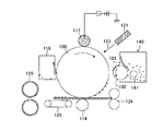
一例として、体積平均粒子径(Dv)が8.0μmの粉砕法による磁性トナー粒子(磁性体の含有量は43.5質量%)にシリカ微粒子の添加量(磁性トナー粒子100質量部に対するシリカの添加部数)を変えて混合したものの理論被覆率と実際の被覆率を求めた(図1、図2参照)。なお、シリカ微粒子としては体積平均粒子径(Dv)が15nmのシリカ微粒子を用いた。理論被覆率を算出する際のシリカ微粒子の真比重は2.2g/cm3、磁性トナーの真比重を1.65g/cm3とし、シリカ微粒子及び磁性トナー粒子に関しては、それぞれ粒径15nm、8.0μmの単分散の粒子とした。
図1に示すように、シリカ微粒子の添加量を増やしていくと理論被覆率は100%を超える。一方、実際の被覆率はシリカ微粒子の添加量と共に変化するが、100%を超える事はない。これは、シリカ微粒子が磁性トナー表面において、一部凝集体として存在しているため、あるいは、シリカ微粒子が真球でない影響が大きい。
また、本発明者らの検討によれば、シリカ微粒子の添加量が同じであっても、外添の手
法によって被覆率が変化することがわかった。すなわち、無機微粒子の添加量から一義に被覆率を求める事は不可能である(図2参照)。なお、外添条件Aは図5の装置を用い、1.0W/g、処理時間5分の条件で混合したものである。外添条件BはヘンシェルミキサーFM10C(三井三池化工機株式会社製)を用い、4000rpm、処理時間2分の条件で混合したものである。
このような理由から、本発明者らは磁性トナー表面のSEM観察により得られる無機微粒子の被覆率を用いた。
これまで述べてきたように、無機微粒子による被覆率を上げる事で部材への付着力を低減できると考えられる。そこで、無機微粒子の被覆率と部材との付着力について検証した。
磁性トナーの被覆率と部材との付着力の関係を、シリカ微粒子による被覆率を変えた球形ポリスチレン粒子とアルミ基板との静止摩擦係数を測定することで間接的に推測した。
具体的には、シリカ微粒子による被覆率(SEM観察から求めた被覆率)を変えた球形ポリスチレン粒子(重量平均粒径(D4)=7.5μm)を用い、被覆率と静止摩擦係数の関係を求めた。
より具体的には、アルミ基板上に、シリカ微粒子を添加した球形ポリスチレン粒子を押圧する。押圧を変化させながら基板に左右に動かし、その際の応力から静止摩擦係数を算出した。これを被覆率の異なる球形ポリスチレン粒子毎に行ない、得られた被覆率と静止摩擦係数の関係を図3に示す。
このような手法で求める静止摩擦係数は、球形ポリスチレン粒子と基板の間に働くVan der Waals力と鏡映力の総和と相関すると考えられる。図3から明らかなように、シリカ微粒子の被覆率が高いと静止摩擦係数が小さくなる事が分かる。この事から、無機微粒子による被覆率が高い磁性トナーは部材との付着力も小さい事が示唆される。
以上の結果をもとに本発明者らが鋭意検討したところ、無機微粒子の被覆率を制御することにより、流動性を高めることができることを見出した。また、前述のように、画像濃度の低下を抑制するために、チャージアップしたトナーの生成を抑制することが重要である。本発明者らの検討の結果、被覆率Aを高くすることにより、流動性を高めることができ、チャージアップしたトナーの発生の抑制を格段に向上させることができることがわかった。これはおそらく、現像ブレードに付着しうる接着性の高いトナーが多少存在したとしても、被覆率Aが高いことにより、磁性トナーと現像ブレードとの付着力が低くなるために、全体として磁性トナーの流動性が高まるためだと考えられる。
In the magnetic toner of the present invention, the coverage of the surface of the magnetic toner particles with the inorganic fine particles is defined as coverage A (%), and the coverage of the inorganic fine particles fixed on the surface of the magnetic toner particles is defined as coverage B (%). Further, the coverage A is 45.0% or more and 70.0% or less, and the ratio of the coverage B to the coverage A [coverage B / coverage A, hereinafter simply referred to as B / A] is 0. It is important that it is 50 or more and 0.85 or less.
The coverage A is preferably 45.0% or more and 65.0% or less, and B / A is preferably 0.55 or more and 0.80 or less.
When the coverage ratio A and B / A satisfy the above ranges, the individual toner particles are separated from the spike development in which the magnetic toner spikes on the developing sleeve are developed as they are in the development region. It becomes possible to greatly approximate to “cloud development” to be developed.
The reason is presumed as follows.
In the development using magnetic toner, the magnetic toner conveyed by the developing sleeve comes into contact with the developing blade and the developing sleeve at the contact portion between the developing blade and the developing sleeve, and is charged by friction at that time. For this reason, if the magnetic toner stays on the developing sleeve without being developed, it repeatedly undergoes friction, resulting in variations in chargeability.
However, the magnetic toner of the present invention has a high coverage ratio A of 45.0% or more on the surface of the magnetic toner particles with inorganic fine particles, so that the van der Waals force and the electrostatic adhesion force with the contacting member are low, and the magnetic toner The toner is less likely to stay on the developing blade or in the vicinity of the developing sleeve. If the coverage A is made larger than 70.0%, it is necessary to add a large amount of inorganic fine particles, and even if the method of external addition is devised, image defects (vertical stripes) are generated due to the free inorganic fine particles. Easy and not preferred.
Here, the covering ratio A, the covering ratio B, and the ratio [B / A] of the covering ratio B to the covering ratio A can be known by the method described later.
The coverage A in the present invention is a coverage including inorganic fine particles that can be easily released, and the coverage B shows a coverage by inorganic fine particles fixed to the surface of the magnetic toner particles that is not released by the releasing operation described later. . The inorganic fine particles represented by the coverage ratio B are fixed to the surface of the magnetic toner particles in a semi-embedded state, and can move on the developing sleeve or the electrostatic latent image carrier even if the magnetic toner receives a share. It is not considered.
On the other hand, the inorganic fine particles represented by the covering ratio A include the fixed inorganic fine particles and the inorganic fine particles present in the upper layer and having a relatively high degree of freedom.
The effect of reducing the van der Waals force and the electrostatic adhesion force as described above is influenced by the inorganic fine particles that can exist between the magnetic toner and between the magnetic toner and each member, and the coverage A is increased. Is considered particularly important in terms of this effect.
First, the van der Waals force (F) generated between the flat plate and the grains is represented by the following equation.
F = H × D / (12Z 2 )
Here, H is H am aker constant, D is the particle diameter of the particles, Z is the distance between the particles and the flat plate.
With regard to Z, it is generally said that attractive force works when the distance is long, and repulsive force works when the distance is very close, and since it has nothing to do with the state of the magnetic toner surface, it is treated as a constant.
From the above formula, the van der Waals force (F) is proportional to the particle size of the particles in contact with the flat plate. When this is applied to the surface of the magnetic toner, the van der Waals force (F) is smaller when the inorganic fine particles having a small particle diameter are in contact with the flat plate than when the magnetic toner particles are in contact with the flat plate. That is, the van der Waals force is smaller when the magnetic toner particles come into contact with the developing sleeve or the developing blade through the inorganic fine particles as the external additive than directly contact with the developing sleeve or the developing blade.
Next, electrostatic adhesion can be rephrased as mirror power. It is known that the mirror power is generally proportional to the square of the charge (q) of the particle and inversely proportional to the square of the distance.
When the magnetic toner is charged, it is not the inorganic fine particles but the surface of the magnetic toner particles that has a charge. For this reason, the mirror force becomes smaller as the distance between the surface of the magnetic toner particles and the flat plate (here, the developing sleeve or the developing blade) increases.
That is, on the surface of the magnetic toner, if the magnetic toner particles are in contact with the flat plate via the inorganic fine particles, the distance between the magnetic toner particle surface and the flat plate can be taken, so that the mirror power is reduced.
As described above, the van der Waals force generated between the magnetic toner and the developing sleeve or the developing blade when the inorganic toner is present on the surface of the magnetic toner particle and the magnetic toner contacts the developing sleeve or the developing blade via the inorganic fine particle. Mirror power decreases. That is, the adhesion between the magnetic toner and the developing sleeve or the developing blade is reduced.
Next, whether the magnetic toner particles are in direct contact with the developing sleeve or the developing blade or via the inorganic fine particles depends on how much the inorganic fine particles cover the surface of the magnetic toner particles, that is, the coverage of the inorganic fine particles.
When the coverage of the inorganic fine particles is high, the chance that the magnetic toner particles are in direct contact with the developing sleeve or the developing blade decreases, and it is considered that the magnetic toner is difficult to stick to the developing sleeve or the developing blade. On the other hand, when the coverage of the inorganic fine particles is low, the magnetic toner tends to stick to the developing sleeve or the developing blade, and tends to stay on the developing blade or in the vicinity of the developing sleeve.
As for the coverage of the inorganic fine particles, assuming that the inorganic fine particles and the magnetic toner are spherical, it is possible to derive the theoretical coverage by a calculation formula described in Patent Document 5 or the like. However, there are many cases where the inorganic fine particles and the magnetic toner are not spherical, and furthermore, the inorganic fine particles may be present in an aggregated state on the surface of the magnetic toner particles. Therefore, the theoretical coverage derived by these methods is the same as that of the present invention. Is not relevant.
Therefore, the present inventors have observed the surface of the magnetic toner with a scanning electron microscope (SEM), and determined the coverage ratio at which the inorganic fine particles actually cover the surface of the magnetic toner particles.
As an example, the amount of silica fine particles added to 100 parts by mass of magnetic toner particles (magnetic toner particles based on 100 parts by mass) is added to magnetic toner particles (content of magnetic material is 43.5% by mass) by a pulverization method having a volume average particle diameter (Dv) of 8.0 μm The theoretical coverage and the actual coverage of the mixture mixed by changing the number of added parts) were obtained (see FIGS. 1 and 2). As silica fine particles, silica fine particles having a volume average particle diameter (Dv) of 15 nm were used. True specific gravity of the silica fine particles at the time of calculating the theoretical coverage was 2.2 g / cm 3, the true specific gravity of the magnetic toner and 1.65 g / cm 3, with respect to the silica fine particles and the magnetic toner particles, each particle size 15 nm, 8 0.0 μm monodisperse particles.
As shown in FIG. 1, as the amount of silica fine particles added is increased, the theoretical coverage exceeds 100%. On the other hand, the actual coverage varies with the amount of silica fine particles added, but does not exceed 100%. This is because the silica fine particles are partially present on the magnetic toner surface as aggregates, or the silica fine particles are not a true sphere.
Further, according to the study by the present inventors, it was found that the coverage ratio was changed by the external addition method even when the addition amount of the silica fine particles was the same. That is, it is impossible to uniquely determine the coverage from the amount of inorganic fine particles added (see FIG. 2). The external addition condition A is a mixture of 1.0 W / g and a processing time of 5 minutes using the apparatus shown in FIG. External addition condition B is a mixture using Henschel mixer FM10C (manufactured by Mitsui Miike Chemical Co., Ltd.) under the conditions of 4000 rpm and a processing time of 2 minutes.
For these reasons, the present inventors used the coverage of inorganic fine particles obtained by SEM observation of the magnetic toner surface.
As described above, it is considered that the adhesion force to the member can be reduced by increasing the coverage with inorganic fine particles. Then, it verified about the coverage of an inorganic fine particle, and the adhesive force with a member.
The relationship between the coverage of the magnetic toner and the adhesion force between the members was indirectly estimated by measuring the coefficient of static friction between the spherical polystyrene particles having a different coverage with silica fine particles and the aluminum substrate.
Specifically, spherical polystyrene particles (weight average particle diameter (D4) = 7.5 μm) with different silica fine particle coverage (coverage obtained from SEM observation) were used, and the relationship between coverage and static friction coefficient was determined. Asked.
More specifically, spherical polystyrene particles added with silica fine particles are pressed onto an aluminum substrate. While changing the pressure, the substrate was moved left and right, and the coefficient of static friction was calculated from the stress at that time. This is performed for each spherical polystyrene particle having a different coverage, and the relationship between the obtained coverage and the static friction coefficient is shown in FIG.
The static friction coefficient obtained by such a method is considered to correlate with the sum of the Van der Waals force and the mirror force acting between the spherical polystyrene particles and the substrate. As can be seen from FIG. 3, the coefficient of static friction decreases when the silica fine particle coverage is high. This suggests that a magnetic toner having a high coverage with inorganic fine particles has a low adhesion to the member.
As a result of extensive studies by the present inventors based on the above results, it has been found that the fluidity can be enhanced by controlling the coverage of the inorganic fine particles. As described above, it is important to suppress the generation of charged-up toner in order to suppress a decrease in image density. As a result of the study by the present inventors, it was found that by increasing the coverage A, the fluidity can be improved and the suppression of the generation of charged-up toner can be significantly improved. This is probably because even if there is some highly adhesive toner that can adhere to the developing blade, the high coverage A reduces the adhesive force between the magnetic toner and the developing blade, so that This is thought to be due to increased liquidity.
一方、B/Aが0.50以上、0.85以下であることは、磁性トナー粒子表面に固着された無機微粒子がある程度存在し、その上にさらに無機微粒子が容易に遊離しうる状態(磁性トナー粒子から離れて挙動できる状態)で、適当量存在していることを意味している。おそらく、この固着された無機微粒子に対して、遊離可能な無機微粒子が滑ることにより、ベアリングのような効果を発揮し、磁性トナー間の凝集力が大幅に低減すると考えら
れる。
本発明者らの検討の結果、上述の付着力低減効果及びベアリング効果は、固着された無機微粒子、及び、容易に遊離しうる無機微粒子がともに、一次粒子の個数平均粒径(D1)において、50nm以下程度の比較的小さな無機微粒子であるときに最大限に得られることがわかった。よって、被覆率A及びBを算出する際には、一次粒子の個数平均一次粒径(D1)が50nm以下の無機微粒子に着目した。
本発明の磁性トナーは、被覆率A、及び、B/Aを特定の範囲とすることにより、磁性トナーと各部材間の付着力を低くし、磁性トナー間の凝集力を大幅に低減することができる。その結果、静電潜像を磁性トナーによって現像する工程において、磁性トナー一粒一粒がほぐれて静電潜像担持体に飛翔するため、上述の外添剤の状態を示す磁性トナーの場合には、クラウド現像が初めて可能となる。特に小型化のために、現像スリーブを小径にした場合に発生しやすい、流動性低下を大幅に減らすことが可能となる。
On the other hand, when B / A is 0.50 or more and 0.85 or less, there are some inorganic fine particles fixed on the surface of the magnetic toner particles, and the inorganic fine particles can be further easily released (magnetic). It means that an appropriate amount is present in a state where it can be moved away from the toner particles. Presumably, the slidable inorganic fine particles slide on the fixed inorganic fine particles, thereby exhibiting an effect like a bearing, and the cohesive force between the magnetic toners is greatly reduced.
As a result of the study by the present inventors, the above-mentioned adhesive force reduction effect and bearing effect are such that the fixed inorganic fine particles and the inorganic fine particles that can be easily released are both in the number average particle diameter (D1) of the primary particles. It was found that the maximum size was obtained when the inorganic fine particles were relatively small of about 50 nm or less. Therefore, when calculating the coverage ratios A and B, attention was focused on inorganic fine particles having a primary particle number average primary particle size (D1) of 50 nm or less.
The magnetic toner of the present invention can reduce the adhesion between the magnetic toner and each member, and greatly reduce the cohesive force between the magnetic toners, by setting the coverage ratio A and B / A within a specific range. Can do. As a result, in the process of developing the electrostatic latent image with the magnetic toner, each magnetic toner is loosened and flies to the electrostatic latent image carrier. Cloud development is possible for the first time. In particular, due to the miniaturization, it is possible to greatly reduce the decrease in fluidity that is likely to occur when the developing sleeve has a small diameter.
また、本発明においては、被覆率Aの変動係数が10.0%以下であることが好ましく、より好ましくは被覆率Aの変動係数が8.0%以下である。被覆率Aの変動係数が10.0%以下であるということは、磁性トナー粒子間、磁性トナー粒子内での被覆率Aが極めて均一であることを意味している。変動係数が10.0%を超える場合は、磁性トナー表面の被覆状態が均一でないため、磁性トナー間の凝集力が低減しにくい。
上記変動係数を10.0%以下にするための手法は特に限定されないが、磁性トナー粒子表面に高度にシリカ微粒子等の金属酸化物微粒子を拡散させることができる、後述するような外添装置や手法を用いることが好ましい。
In the present invention, the variation coefficient of the coverage A is preferably 10.0% or less, and more preferably the variation coefficient of the coverage A is 8.0% or less. That the coefficient of variation of the coverage A is 10.0% or less means that the coverage A between the magnetic toner particles and within the magnetic toner particles is extremely uniform. When the coefficient of variation exceeds 10.0%, the coating state on the surface of the magnetic toner is not uniform, and it is difficult to reduce the cohesive force between the magnetic toners.
The method for reducing the coefficient of variation to 10.0% or less is not particularly limited, but an external addition device as described later, which can highly diffuse metal oxide fine particles such as silica fine particles on the surface of the magnetic toner particles. It is preferable to use a technique.
さらに、本発明の磁性トナーは、重量平均粒径(D4)の個数平均粒径(D1)に対する比[D4/D1]が1.30以下であることが重要である。好ましくは1.26以下である。上述のような粒度分布がシャープな磁性トナー粒子に、被覆率A、B/A、そしてチタン酸ストロンチウム微粒子の遊離率が特定の範囲を満足する外添状態とすることにより、初めて「苛酷環境放置後の濃度低下」を抑制できるようになる。
この理由について筆者らは以下のように推測している。
磁性トナーを苛酷環境のような厳しい条件に放置すると、磁性トナーの内部から結着樹脂の低分子量成分や離型剤などが染み出してくるため、現像スリーブや現像容器内で磁性トナーの凝集性が高まることになる。粒度分布が狭い磁性トナーでは、磁性トナーが均等に現像スリーブや隣接する磁性トナーに接することになり、苛酷環境に放置した際に生じる凝集塊が小さくなる。これにより、粒度分布を上述の範囲に制御した本発明の磁性トナーは、苛酷環境放置後でも現像スリーブ上の穂立ちが均一で低いものであることにより、磁性トナーがほぐれて静電潜像担持体に飛翔するクラウド現像になる。
また、粒度分布が狭い磁性トナーではチタン酸ストロンチウム微粒子が磁性トナー粒子に均一に付着しやすいため、粒子間でのチタン酸ストロンチウム微粒子の付着量にバラツキが少なくなる。これにより、現像スリーブから静電潜像担持体へ飛翔する磁性トナーにおけるチタン酸ストロンチウム微粒子量が均一になり、剥離帯電による帯電性のバラツキを抑制する効果がより大きくなる。
以上、被覆率A、B/A、チタン酸ストロンチウム微粒子の遊離率、そして粒度分布を本件の範囲内に制御することにより、現像工程においてクラウド現像と効率的な剥離帯電の発生を達成でき、苛酷環境放置後においてもバイアス追従性が高まり、濃度低下とカブリを抑制することができると考える。
Further, in the magnetic toner of the present invention, it is important that the ratio [D4 / D1] of the weight average particle diameter (D4) to the number average particle diameter (D1) is 1.30 or less. Preferably it is 1.26 or less. For the first time, the magnetic toner particles having a sharp particle size distribution as described above are subjected to an external addition state in which the coverage ratios A and B / A and the release rate of the strontium titanate fine particles satisfy a specific range. It becomes possible to suppress the “lower density drop”.
The authors speculate as follows for this reason.
If the magnetic toner is left under harsh conditions such as a harsh environment, the low molecular weight component of the binder resin and the release agent ooze out from the inside of the magnetic toner. Will increase. In a magnetic toner having a narrow particle size distribution, the magnetic toner uniformly contacts the developing sleeve and the adjacent magnetic toner, and agglomerates generated when left in a harsh environment are reduced. As a result, the magnetic toner of the present invention in which the particle size distribution is controlled within the above range has a uniform and low rise on the developing sleeve even after being left in a harsh environment. It becomes cloud development that flies to the body.
Further, in the magnetic toner having a narrow particle size distribution, the strontium titanate fine particles are likely to adhere uniformly to the magnetic toner particles, so that the amount of strontium titanate fine particles adhering between the particles is less varied. As a result, the amount of strontium titanate fine particles in the magnetic toner flying from the developing sleeve to the electrostatic latent image carrier becomes uniform, and the effect of suppressing variation in chargeability due to peeling charging is further increased.
As described above, by controlling the coverage A, B / A, the release rate of strontium titanate fine particles, and the particle size distribution within the range of this case, it is possible to achieve cloud development and efficient generation of peeling charge in the development process. It is considered that the bias followability is enhanced even after being left in the environment, and density reduction and fogging can be suppressed.
本発明において、磁性トナーの結着樹脂としては、ビニル系樹脂、ポリエステル系樹脂等が挙げられるが、特に限定されず従来公知の樹脂を用いることができる。
具体的には、ポリスチレン、スチレン−プロピレン共重合体、スチレン−ビニルトルエン共重合体、スチレン−アクリル酸メチル共重合体、スチレン−アクリル酸エチル共重合体、スチレン−アクリル酸ブチル共重合体、スチレン−アクリル酸オクチル共重合体、ス
チレン−メタクリル酸メチル共重合体、スチレン−メタクリル酸エチル共重合体、スチレン−メタクリル酸ブチル共重合体、スチレン−メタクリル酸オクチル共重合体、スチレン−ブタジエン共重合体、スチレン−イソプレン共重合体、スチレン−マレイン酸共重合体、スチレン−マレイン酸エステル共重合体などのスチレン系共重合体、ポリアクリル酸エステル、ポリメタクリル酸エステル、ポリ酢酸ビニル等を用いることができ、これらは単独で又は複数種を組み合わせて用いることができる。この中でも特にスチレン系共重合体及びポリエステル樹脂が現像特性、定着性等の点で好ましい。
In the present invention, examples of the binder resin for the magnetic toner include vinyl resins and polyester resins, but are not particularly limited, and conventionally known resins can be used.
Specifically, polystyrene, styrene-propylene copolymer, styrene-vinyltoluene copolymer, styrene-methyl acrylate copolymer, styrene-ethyl acrylate copolymer, styrene-butyl acrylate copolymer, styrene -Octyl acrylate copolymer, styrene-methyl methacrylate copolymer, styrene-ethyl methacrylate copolymer, styrene-butyl methacrylate copolymer, styrene-octyl methacrylate copolymer, styrene-butadiene copolymer Styrene-based copolymers such as styrene-isoprene copolymer, styrene-maleic acid copolymer, styrene-maleic acid ester copolymer, polyacrylic acid ester, polymethacrylic acid ester, polyvinyl acetate, etc. Can be used alone or in combination It is possible to have. Of these, styrene copolymers and polyester resins are particularly preferred from the standpoints of development characteristics and fixability.
本発明の磁性トナーのガラス転移温度(Tg)は40℃以上、70℃以下であることが好ましい。磁性トナーのガラス転移温度が40℃以上、70℃以下であると、良好な定着性を維持しつつ保存安定性、そして耐久性を向上できる。 The glass transition temperature (Tg) of the magnetic toner of the present invention is preferably 40 ° C. or higher and 70 ° C. or lower. When the glass transition temperature of the magnetic toner is 40 ° C. or higher and 70 ° C. or lower, storage stability and durability can be improved while maintaining good fixability.
本発明の磁性トナーにおいて、荷電制御剤を添加することが好ましい。
なお、本発明においては、負帯電性トナーであることが好ましい。
負帯電用の荷電制御剤としては、有機金属錯化合物、キレート化合物が有効であり、モノアゾ金属錯化合物;アセチルアセトン金属錯化合物;芳香族ハイドロキシカルボン酸または芳香族ダイカルボン酸の金属錯化合物等が挙げられる。市販品の具体例として、Spilon Black TRH、T−77、T−95(保土谷化学工業(株))、BONTRON(登録商標)S−34、S−44、S−54、E−84、E−88、E−89(オリエント化学社)が挙げられる。
これらの荷電制御剤は単独、或いは二種以上組み合わせて用いることが可能である。これらの荷電制御剤の使用量は、磁性トナーの帯電量の点から、結着樹脂100質量部当たり0.1乃至10.0質量部であることが好ましく、より好ましくは0.1乃至5.0質量部である。
In the magnetic toner of the present invention, it is preferable to add a charge control agent.
In the present invention, a negatively chargeable toner is preferable.
As the charge control agent for negative charging, organometallic complex compounds and chelate compounds are effective, and monoazo metal complex compounds; acetylacetone metal complex compounds; metal complexes of aromatic hydroxycarboxylic acids or aromatic dicarboxylic acids, etc. It is done. Specific examples of commercially available products include Spiron Black TRH, T-77, T-95 (Hodogaya Chemical Co., Ltd.), BONTRON (registered trademark) S-34, S-44, S-54, E-84, E -88, E-89 (Orient Chemical).
These charge control agents can be used alone or in combination of two or more. The amount of these charge control agents used is preferably 0.1 to 10.0 parts by weight, more preferably 0.1 to 5.5 parts per 100 parts by weight of the binder resin from the viewpoint of the charge amount of the magnetic toner. 0 parts by mass.
本発明の磁性トナーには、定着性向上のために必要に応じて離型剤を配合しても良い。離型剤としては公知の全ての離型剤を用いる事が出来る。具体的には、パラフィンワックス、マイクロクリスタリンワックス、ペトロラクタム等の石油系ワックス及びその誘導体、モンタンワックス及びその誘導体、フィッシャートロプシュ法による炭化水素ワックス及びその誘導体、ポリエチレン、ポリプロピレンに代表されるポリオレフィンワックス及びその誘導体、カルナバワックス、キャンデリラワックス等天然ワックス及びその誘導体、エステルワックスなどが挙げられる。ここで、誘導体とは酸化物や、ビニル系モノマーとのブロック共重合物、グラフト変性物を含む。また、エステルワックスとしては1官能エステルワックス、2官能エステルワックスをはじめ、4官能や6官能等の多官能エステルワックスを用いる事が出来る。
本発明の磁性トナーに離型剤を用いる場合、その配合量は、結着樹脂100質量部に対して、0.5質量部以上、10質量部以下であることが好ましい。離型剤の配合量が上記範囲であると、定着性が向上するとともに、磁性トナーの保存安定性が損なわれない。
また、離型剤は、樹脂製造時、樹脂を溶剤に溶解し、樹脂溶液温度を上げ、撹拌しながら添加混合する方法や、磁性トナー製造中の溶融混練時に添加する方法などにより結着樹脂に配合することができる。
離型剤の示差走査熱量計(DSC)で測定される最大吸熱ピークのピーク温度(以下、融点ともいう)は、60℃以上、140℃以下である事が好ましく、より好ましくは70℃以上、130℃以下である。最大吸熱ピークのピーク温度(融点)が60℃以上、140℃以下であると定着時に磁性トナーが可塑化しやすく、定着性が良化する。また、長期間保存しても離型剤の染み出し等も生じ難く好ましい。
本発明において、離型剤の最大吸熱ピークのピーク温度は、示差走査熱量分析装置「Q1000」(TA Instruments社製)を用いてASTM D3418−82に準じて測定する。装置検出部の温度補正はインジウムと亜鉛の融点を用い、熱量の補正についてはインジウムの融解熱を用いる。
具体的には、測定試料約10mgを精秤し、これをアルミニウム製のパンの中に入れ、リファレンスとして空のアルミニウム製のパンを用い、測定温度範囲30〜200℃の間で、昇温速度10℃/minで測定を行う。尚、測定においては、一度200℃まで昇温させ、続いて10℃/minで30℃まで降温し、その後に再度、10℃/minで昇温を行う。この2度目の昇温過程での温度30〜200℃の範囲におけるDSC曲線から離型剤の最大吸熱ピークのピーク温度を求める。
In the magnetic toner of the present invention, a release agent may be blended as necessary to improve the fixing property. As the release agent, all known release agents can be used. Specifically, petroleum waxes such as paraffin wax, microcrystalline wax, petrolactam and derivatives thereof, montan wax and derivatives thereof, hydrocarbon waxes and derivatives thereof according to the Fischer-Tropsch method, polyolefin waxes represented by polyethylene and polypropylene, and Examples thereof include natural waxes such as derivatives thereof, carnauba wax and candelilla wax, derivatives thereof, and ester waxes. Here, the derivatives include oxides, block copolymers with vinyl monomers, and graft modified products. As the ester wax, monofunctional ester wax, bifunctional ester wax, and other polyfunctional ester waxes such as tetrafunctional and hexafunctional can be used.
When a release agent is used in the magnetic toner of the present invention, the blending amount is preferably 0.5 parts by mass or more and 10 parts by mass or less with respect to 100 parts by mass of the binder resin. When the compounding amount of the release agent is within the above range, the fixability is improved and the storage stability of the magnetic toner is not impaired.
The mold release agent is added to the binder resin by dissolving the resin in a solvent at the time of resin production, increasing the temperature of the resin solution, adding and mixing with stirring, or adding it at the time of melt kneading during magnetic toner production. Can be blended.
The peak temperature of the maximum endothermic peak (hereinafter also referred to as melting point) measured by a differential scanning calorimeter (DSC) of the release agent is preferably 60 ° C. or higher and 140 ° C. or lower, more preferably 70 ° C. or higher. It is 130 degrees C or less. When the peak temperature (melting point) of the maximum endothermic peak is 60 ° C. or more and 140 ° C. or less, the magnetic toner is easily plasticized at the time of fixing, and the fixability is improved. Further, it is preferable that the release agent does not bleed out even if stored for a long time.
In the present invention, the peak temperature of the maximum endothermic peak of the release agent is measured according to ASTM D3418-82 using a differential scanning calorimeter “Q1000” (manufactured by TA Instruments). The temperature correction of the device detection unit uses the melting points of indium and zinc, and the correction of heat uses the heat of fusion of indium.
Specifically, about 10 mg of a measurement sample is precisely weighed, placed in an aluminum pan, an empty aluminum pan is used as a reference, and the temperature rise rate is within a measurement temperature range of 30 to 200 ° C. Measurement is performed at 10 ° C./min. In the measurement, the temperature is once raised to 200 ° C., subsequently lowered to 30 ° C. at 10 ° C./min, and then heated again at 10 ° C./min. The peak temperature of the maximum endothermic peak of the release agent is determined from the DSC curve in the temperature range of 30 to 200 ° C. in the second temperature raising process.
本発明において、磁性トナー中に含まれる磁性体としては、マグネタイト、マグヘマイト、フェライト等の酸化鉄;鉄、コバルト、ニッケルのような金属或はこれらの金属アルミニウム、コバルト、銅、鉛、マグネシウム、スズ、亜鉛、アンチモン、ベリリウム、ビスマス、カドミウム、カルシウム、マンガン、セレン、チタン、タングステン、バナジウムのような金属の合金及びその混合物等が挙げられる。
これらの磁性体は一次粒子の個数平均粒径が2μm以下であることが好ましく、より好ましくは0.05乃至0.50μmである。
また、79.6kA/m印加での磁気特性として、抗磁力(Hc)1.6乃至12.0kA/mであることが好ましく、磁化の強さ(σs)が30乃至90Am2/kgであることが好ましく、より好ましくは40乃至80Am2/kgであり、残留磁化(σr)が1乃至10Am2/kgであることが好ましく、より好ましくは1.5乃至8Am2/kgである。
本発明の磁性トナーは、磁性体の含有量が、35質量%以上、50質量%以下であることが好ましく、より好ましくは、40質量%以上、50質量%以下である。
磁性体の含有量をこの範囲とすることにより、本発明において望ましい誘電特性に制御しやすい。
磁性体の含有量が、35質量%未満の場合には、誘電特性を調整しにくくなるだけでなく、現像スリーブ内のマグネットロールとの磁気引力が低下し、カブリが発生しやすくなる傾向にある。一方、50質量%を超える場合には、上記同様に誘電特性を調整しにくくなるだけでなく、現像性が低下しやすい傾向にある。
なお、磁性トナー中の磁性体の含有量は、パーキンエルマー社製熱分析装置、TGA7を用いて測定することができる。測定方法は、窒素雰囲気下において昇温速度25℃/分で常温から900℃まで、磁性トナーを加熱し、100〜750℃まで間の減量質量を磁性トナーから磁性体を除いた成分の質量とし、残存質量を磁性体量とする。
In the present invention, the magnetic material contained in the magnetic toner includes iron oxides such as magnetite, maghemite, and ferrite; metals such as iron, cobalt, and nickel; or these metal aluminum, cobalt, copper, lead, magnesium, tin And alloys of metals such as zinc, antimony, beryllium, bismuth, cadmium, calcium, manganese, selenium, titanium, tungsten, vanadium, and mixtures thereof.
These magnetic materials preferably have a primary particle number average particle size of 2 μm or less, more preferably 0.05 to 0.50 μm.
Further, as magnetic characteristics when 79.6 kA / m is applied, the coercive force (Hc) is preferably 1.6 to 12.0 kA / m, and the magnetization strength (σs) is 30 to 90 Am 2 / kg. More preferably, it is 40 to 80 Am 2 / kg, and the residual magnetization (σr) is preferably 1 to 10 Am 2 / kg, more preferably 1.5 to 8 Am 2 / kg.
In the magnetic toner of the present invention, the content of the magnetic material is preferably 35% by mass or more and 50% by mass or less, and more preferably 40% by mass or more and 50% by mass or less.
By setting the content of the magnetic substance within this range, it is easy to control the dielectric characteristics desirable in the present invention.
When the content of the magnetic material is less than 35% by mass, not only the dielectric characteristics are difficult to adjust, but also the magnetic attractive force with the magnet roll in the developing sleeve tends to be reduced, and fogging tends to occur. . On the other hand, when it exceeds 50% by mass, not only does it become difficult to adjust the dielectric characteristics as described above, but also the developability tends to decrease.
The content of the magnetic substance in the magnetic toner can be measured using a thermal analyzer, TGA7, manufactured by PerkinElmer. In the measurement method, the magnetic toner is heated from room temperature to 900 ° C. at a temperature rising rate of 25 ° C./min in a nitrogen atmosphere, and the weight loss between 100 and 750 ° C. is defined as the mass of the component excluding the magnetic material from the magnetic toner. The remaining mass is defined as the amount of magnetic material.
本発明の磁性トナーは磁場79.6kA/mにおける、残留磁化(σr)の磁化の強さ(σs)に対する比[σr/σs]が0.09以下である事が好ましく、より好ましくは0.06以下である。[σr/σs]が小さいと言う事は、磁性トナーの残留磁化が小さい事を意味する。
ここで、磁性一成分現像について考えると、トナー担持体内部に存在する多極のマグネットの影響で磁性トナーはトナー担持体に取り込まれたり、吐き出されたりする。吐き出された磁性トナー(トナー担持体から離れた磁性トナー)は[σr/σs]が小さいと磁気凝集し難い。このような磁性トナーが再び取り込み極でトナー担持体に付着し、当接部に突入すると磁気凝集していないため、トナー量の規制がきちんと行われ、トナー担持体上の磁性トナー量が安定する。このため、現像ブレードと現像スリーブとの当接部での磁性トナー量が安定化し、該当接部での磁性トナーの入れ替わりが極めて良好となり、帯電量分布が非常にシャープになる。その結果、ゴーストが良化するばかりでなく、画像濃度がより高く、カブリの少ない画像を得る事ができる。
なお、[σr/σs]は、磁性トナーが含有する磁性体の粒径、形状、および、磁性体を製造する際に添加する添加剤を調整することで、上記範囲に調整することが可能である。具体的には、磁性体にシリカやリン等を添加する事によってσsを高く保ったまま、σrをより低くする事が可能となる。また、磁性体の表面積が小さいほどσrは小さくなり、
形状は八面体よりも磁気異方性が小さな球形の方がσrは小さくなる。これらを組み合わ
せる事により、σrを非常に低くする事が可能となり、[σr/σs]を0.09以下に
制御する事が出来る。
本発明において磁性トナー、及び磁性体の磁化の強さ(σs)及び残留磁化(σr)は、振動型磁力計VSM P−1−10(東英工業社製)を用いて、25℃の室温にて外部磁場79.6kA/mで測定する。磁気特性を、外部磁場が79.6kA/mにて測定する理由についてであるが、一般的に、トナー担持体中に固定されているマグネットローラーの現像極の磁力は79.6kA/m(1000エルステッド)前後である。このため、外部磁場79.6kA/mで残留磁化を測定する事により現像領域でのトナー挙動を捉える事が出来るからである。
In the magnetic toner of the present invention, the ratio [σr / σs] of the residual magnetization (σr) to the magnetization intensity (σs) at a magnetic field of 79.6 kA / m is preferably 0.09 or less, more preferably 0.8. 06 or less. That [σr / σs] is small means that the residual magnetization of the magnetic toner is small.
Here, considering magnetic one-component development, the magnetic toner is taken into or discharged from the toner carrier due to the influence of the multipolar magnets present inside the toner carrier. The discharged magnetic toner (magnetic toner separated from the toner carrier) is difficult to be magnetically aggregated when [σr / σs] is small. Since such magnetic toner adheres to the toner carrier again at the take-in pole and does not agglomerate when entering the contact portion, the toner amount is properly regulated and the magnetic toner amount on the toner carrier is stabilized. . For this reason, the amount of magnetic toner at the contact portion between the developing blade and the developing sleeve is stabilized, the replacement of the magnetic toner at the contact portion becomes extremely good, and the charge amount distribution becomes very sharp. As a result, not only is the ghost improved, but an image with higher image density and less fog can be obtained.
[Σr / σs] can be adjusted to the above range by adjusting the particle size and shape of the magnetic material contained in the magnetic toner and the additive added when the magnetic material is produced. is there. Specifically, by adding silica, phosphorus or the like to the magnetic material, it is possible to lower σr while keeping σs high. Also, the smaller the surface area of the magnetic material, the smaller σr,
Σr is smaller in a spherical shape with a smaller magnetic anisotropy than in an octahedron. By combining these, it becomes possible to make σr very low, and [σr / σs] can be controlled to 0.09 or less.
In the present invention, the magnetization intensity (σs) and residual magnetization (σr) of the magnetic toner and the magnetic material are measured at room temperature of 25 ° C. using a vibration type magnetometer VSM P-1-10 (manufactured by Toei Kogyo Co., Ltd.). At an external magnetic field of 79.6 kA / m. The reason is that the magnetic characteristics are measured at an external magnetic field of 79.6 kA / m. Generally, the magnetic force of the developing pole of the magnet roller fixed in the toner carrier is 79.6 kA / m (1000 Oersted). For this reason, the toner behavior in the development region can be grasped by measuring the residual magnetization with an external magnetic field of 79.6 kA / m.
本発明の磁性トナーは、磁性トナー粒子表面に無機微粒子を含有する。
磁性トナー粒子表面に存在する無機微粒子としてはシリカ微粒子、チタニア微粒子、及びアルミナ微粒子が挙げられ、それら微粒子表面に疎水化処理を施したものも好適に用いる事が出来る。
また、本発明において磁性トナー粒子表面に存在する無機微粒子は、シリカ微粒子、チタニア微粒子、及びアルミナ微粒子からなる群より選ばれた少なくとも1種の金属酸化物微粒子を含有し、該金属酸化物微粒子中の85質量%以上がシリカ微粒子であることが重要である。さらには、該金属酸化物微粒子中の90質量%以上がシリカ微粒子であることが好ましい。
これは、帯電性付与及び流動性付与の点で、シリカ微粒子が最もバランスが優れているだけでなく、磁性トナー間の凝集力低減の点でも優れているためである。
磁性トナー間の凝集力低減の点でシリカ微粒子が優れている理由については定かではないが、おそらくシリカ微粒子同士の滑り性の点で、前述したようなベアリング効果が大きく作用するためであると推測している。
さらに、磁性トナー粒子表面に固着された無機微粒子はシリカ微粒子が主成分であることが好ましい。具体的には、磁性トナー粒子表面に固着された無機微粒子は、シリカ微粒子、チタニア微粒子、及びアルミナ微粒子からなる群より選ばれた少なくとも1種の金属酸化物微粒子を含有し、該金属酸化物微粒子中の80質量%以上がシリカ微粒子であることが好ましい。より好ましくは90質量%以上がシリカ微粒子である。これは、上記と同様の理由であると推察しており、帯電性付与及び流動性付与の点でシリカ微粒子が最も優れており、これにより磁性トナーの帯電の立ち上がりが素早くなる。その結果、高い画像濃度を得る事が出来、非常に好ましい。
ここで、磁性トナー粒子表面に存在する金属酸化物微粒子中の85質量%以上、及び磁性トナー粒子表面に固着された金属酸化物粒子中の80質量%以上を、それぞれシリカ微粒子とするには、無機微粒子添加の量やタイミングにより調整すればよい。
また、後述する無機微粒子の定量方法によりその存在量を確認することが可能である。
The magnetic toner of the present invention contains inorganic fine particles on the surface of the magnetic toner particles.
Examples of the inorganic fine particles present on the surface of the magnetic toner particles include silica fine particles, titania fine particles, and alumina fine particles, and those obtained by subjecting the surface of the fine particles to a hydrophobizing treatment can also be suitably used.
In the present invention, the inorganic fine particles present on the surface of the magnetic toner particles contain at least one metal oxide fine particle selected from the group consisting of silica fine particles, titania fine particles, and alumina fine particles. It is important that 85% by mass or more of the silica particles are silica fine particles. Furthermore, 90% by mass or more of the metal oxide fine particles are preferably silica fine particles.
This is because silica fine particles not only have the best balance in terms of imparting charging properties and fluidity, but also in terms of reducing cohesion between magnetic toners.
The reason why silica fine particles are superior in terms of reducing the cohesive force between magnetic toners is not clear, but it is presumed that the above-mentioned bearing effect acts largely in terms of slipperiness between silica fine particles. doing.
Further, the inorganic fine particles fixed to the surface of the magnetic toner particles are preferably composed mainly of silica fine particles. Specifically, the inorganic fine particles fixed to the surfaces of the magnetic toner particles contain at least one metal oxide fine particle selected from the group consisting of silica fine particles, titania fine particles, and alumina fine particles, and the metal oxide fine particles It is preferable that 80 mass% or more of them are silica fine particles. More preferably, 90% by mass or more is silica fine particles. This is presumed to be due to the same reason as described above, and the silica fine particles are the most excellent in terms of imparting chargeability and fluidity, whereby the rise of the charge of the magnetic toner is quickened. As a result, a high image density can be obtained, which is very preferable.
Here, 85% by mass or more in the metal oxide fine particles present on the surface of the magnetic toner particles and 80% by mass or more in the metal oxide particles fixed on the magnetic toner particle surfaces are respectively made into silica fine particles. What is necessary is just to adjust with the quantity and timing of inorganic fine particle addition.
Further, the abundance can be confirmed by a method for quantifying inorganic fine particles described later.
本発明における無機微粒子の一次粒子の個数平均粒径(D1)は、5nm以上、50nm以下であることが好ましい。より好ましくは一次粒子の個数平均粒径(D1)が10nm以上、35nm以下である。
無機微粒子の一次粒子の個数平均粒径(D1)が上記範囲であることにより、被覆率A、及びB/Aを適正に制御しやすい。一次粒子の個数平均粒径(D1)が5nm未満であると、無機微粒子同士が凝集しやすく、B/Aの値が大きくなりにくいだけでなく、被覆率Aの変動係数が大きくなりやすい。一方、一次粒子の個数平均粒径(D1)が50nmより大きいと、無機微粒子の添加量を多くしても、被覆率Aが小さくなりやすく、さらに無機微粒子が磁性トナー粒子に固着しにくいため、B/Aの値も小さくなりやすい。すなわち、一次粒子の個数平均粒径(D1)が50nmより大きい場合には、前述の付着力低減やベアリング効果が得られにくい。
The number average particle diameter (D1) of the primary particles of the inorganic fine particles in the present invention is preferably 5 nm or more and 50 nm or less. More preferably, the number average particle diameter (D1) of the primary particles is 10 nm or more and 35 nm or less.
When the number average particle diameter (D1) of the primary particles of the inorganic fine particles is within the above range, the coverage ratio A and B / A can be easily controlled appropriately. When the number average particle diameter (D1) of the primary particles is less than 5 nm, the inorganic fine particles are likely to aggregate, and the B / A value is not easily increased, and the coefficient of variation of the coverage A is likely to be increased. On the other hand, if the number average particle diameter (D1) of the primary particles is larger than 50 nm, the coverage A tends to decrease even if the amount of inorganic fine particles added is increased, and the inorganic fine particles are not easily fixed to the magnetic toner particles. The value of B / A tends to be small. That is, when the number average particle diameter (D1) of the primary particles is larger than 50 nm, it is difficult to obtain the above-described adhesion reduction and bearing effect.
本発明に用いる無機微粒子は、疎水化処理を施したものであることが好ましく、メタノ
ール滴定試験によって測定された疎水化度が40%以上、より好ましくは50%以上となるように疎水化処理したものが特に好ましい。
上記疎水化処理の方法としては、有機ケイ素化合物、シリコーンオイル、長鎖脂肪酸等で処理する方法が挙げられる。
上記有機ケイ素化合物としては、ヘキサメチルジシラザン、トリメチルシラン、トリメチルエトキシシラン、イソブチルトリメトキシシラン、トリメチルクロロシラン、ジメチルジクロロシラン、メチルトリクロロシラン、ジメチルエトキシシラン、ジメチルジメトキシシラン、ジフェニルジエトキシシラン、ヘキサメチルジシロキサン等が挙げられる。これらは一種或いは二種以上の混合物で用いられる。
上記シリコーンオイルとしては、ジメチルシリコーンオイル、メチルフェニルシリコーンオイル、α−メチルスチレン変性シリコーンオイル、クロルフェニルシリコーンオイル、フッ素変性シリコーンオイル等が挙げられる。
上記長鎖脂肪酸は炭素数が10乃至22の脂肪酸を好適に用いる事が出来、直鎖脂肪酸であっても、分岐脂肪酸であっても良い。また、飽和脂肪酸、不飽和脂肪酸のいずれも用いる事が可能である。
この中で、炭素数が10乃至22の直鎖の飽和脂肪酸は無機微粒子表面を均一に処理し易く、非常に好ましい。
該直鎖の飽和脂肪酸としては、カプリン酸、ラウリン酸、ミルスチン酸、パルミチン酸、ステアリン酸、アラキジン酸、ベヘン酸等が挙げられる。
本発明に用いられる無機微粒子において、無機微粒子はシリコーンオイルにより処理されたものが好ましく、より好ましくは、無機微粒子を有機ケイ素化合物とシリコーンオイルにより処理したものである。疎水化度が好適に制御できるからである。
無機微粒子をシリコーンオイルで処理する方法としては、例えば、有機ケイ素化合物で処理された無機微粒子とシリコーンオイルとをヘンシェルミキサー等の混合機を用いて直接混合する方法や、無機微粒子にシリコーンオイルを噴霧する方法が挙げられる。或いは、適当な溶剤にシリコーンオイルを溶解又は分散させた後、無機微粒子を加えて混合し、溶剤を除去する方法でもよい。
シリコーンオイルの処理量は、良好な疎水性を得るために、無機微粒子100質量部に対し1質量部以上、40質量部以下であることが好ましく、3質量部以上、35質量部以下であることがより好ましい。
本発明で用いられるシリカ微粒子、チタニア微粒子、及びアルミナ微粒子は磁性トナーに良好な流動性を付与させる為に、窒素吸着によるBET法で測定した比表面積(BET比表面積)が20m2/g以上、350m2/g以下のものが好ましく、25m2/g以上、300m2/g以下のものがより好ましい。
上記窒素吸着によるBET法で測定した比表面積(BET比表面積)の測定は、JIS
Z8830(2001年)に準じて行う。測定装置としては、定容法によるガス吸着法を測定方式として採用している「自動比表面積・細孔分布測定装置 TriStar3000(島津製作所社製)」を用いる。
ここで、無機微粒子の添加量は、磁性トナー粒子100質量部に対して、無機微粒子1.5質量部以上、3.0質量部以下であることが好ましく、より好ましくは、1.5質量部以上、2.6質量部以下、さらに好ましくは、1.8質量部以上、2.6質量部以下である。
無機微粒子の添加量が上記範囲であることにより、被覆率A、及びB/Aを適正に制御しやすく、さらに画像濃度やカブリの点でも好ましい。
無機微粒子の添加量が3.0質量部を超える場合には、外添装置や外添方法を工夫しても、無機微粒子が遊離することに起因して、画像上にスジなどが発生しやすくなる。
本発明の磁性トナーには、上記無機微粒子に加えて、一次粒子の個数平均粒径(D1)が80nm以上、3μm以下の粒子を添加してもよい。例えばフッ素樹脂粉末、ステアリン酸亜鉛粉末、ポリフッ化ビニリデン粉末の如き滑剤;酸化セリウム粉末、炭化硅素粉末などの研磨剤;シリカ等のスペーサー粒子を本発明の効果に影響を与えない程度に少量用
いることもできる。
The inorganic fine particles used in the present invention are preferably those subjected to a hydrophobic treatment, and have been subjected to a hydrophobic treatment so that the degree of hydrophobicity measured by a methanol titration test is 40% or more, more preferably 50% or more. Those are particularly preferred.
Examples of the hydrophobizing treatment include treatment with an organosilicon compound, silicone oil, long chain fatty acid and the like.
Examples of the organosilicon compound include hexamethyldisilazane, trimethylsilane, trimethylethoxysilane, isobutyltrimethoxysilane, trimethylchlorosilane, dimethyldichlorosilane, methyltrichlorosilane, dimethylethoxysilane, dimethyldimethoxysilane, diphenyldiethoxysilane, and hexamethyl. Examples thereof include disiloxane. These may be used alone or as a mixture of two or more.
Examples of the silicone oil include dimethyl silicone oil, methylphenyl silicone oil, α-methylstyrene modified silicone oil, chlorophenyl silicone oil, and fluorine modified silicone oil.
As the long-chain fatty acid, a fatty acid having 10 to 22 carbon atoms can be suitably used, and it may be a linear fatty acid or a branched fatty acid. In addition, both saturated fatty acids and unsaturated fatty acids can be used.
Among these, straight-chain saturated fatty acids having 10 to 22 carbon atoms are very preferable because the surface of the inorganic fine particles can be easily treated uniformly.
Examples of the linear saturated fatty acid include capric acid, lauric acid, myristic acid, palmitic acid, stearic acid, arachidic acid, and behenic acid.
In the inorganic fine particles used in the present invention, the inorganic fine particles are preferably treated with silicone oil, and more preferably, the inorganic fine particles are treated with an organosilicon compound and silicone oil. This is because the degree of hydrophobicity can be suitably controlled.
Examples of the method of treating inorganic fine particles with silicone oil include a method of directly mixing inorganic fine particles treated with an organosilicon compound and silicone oil using a mixer such as a Henschel mixer, or spraying silicone oil onto inorganic fine particles. The method of doing is mentioned. Alternatively, a method may be used in which silicone oil is dissolved or dispersed in a suitable solvent, and then inorganic fine particles are added and mixed to remove the solvent.
In order to obtain good hydrophobicity, the treatment amount of the silicone oil is preferably 1 part by mass or more and 40 parts by mass or less, and preferably 3 parts by mass or more and 35 parts by mass or less with respect to 100 parts by mass of the inorganic fine particles. Is more preferable.
The silica fine particles, titania fine particles, and alumina fine particles used in the present invention have a specific surface area (BET specific surface area) measured by a BET method by nitrogen adsorption of 20 m 2 / g or more in order to impart good fluidity to the magnetic toner. The thing of 350 m < 2 > / g or less is preferable, and the thing of 25 m < 2 > / g or more and 300 m < 2 > / g or less is more preferable.
The specific surface area (BET specific surface area) measured by the BET method by nitrogen adsorption is measured according to JIS.
This is performed according to Z8830 (2001). As a measuring device, an “automatic specific surface area / pore distribution measuring device TriStar 3000 (manufactured by Shimadzu Corporation)” which employs a gas adsorption method by a constant volume method as a measuring method is used.
Here, the addition amount of the inorganic fine particles is preferably 1.5 parts by mass or more and 3.0 parts by mass or less, more preferably 1.5 parts by mass with respect to 100 parts by mass of the magnetic toner particles. The amount is 2.6 parts by mass or less, more preferably 1.8 parts by mass or more and 2.6 parts by mass or less.
When the addition amount of the inorganic fine particles is within the above range, the coverages A and B / A can be easily controlled appropriately, and the image density and fogging are also preferable.
When the added amount of inorganic fine particles exceeds 3.0 parts by mass, streaks or the like are likely to occur on the image due to the liberation of the inorganic fine particles even if the external addition device or external addition method is devised. Become.
In addition to the inorganic fine particles, particles having a primary particle number average particle diameter (D1) of 80 nm or more and 3 μm or less may be added to the magnetic toner of the present invention. For example, use a small amount of lubricant such as fluororesin powder, zinc stearate powder and polyvinylidene fluoride powder; abrasive such as cerium oxide powder and silicon carbide powder; and spacer particles such as silica so as not to affect the effect of the present invention. You can also.
<無機微粒子の定量方法>
(1)磁性トナー中のシリカ微粒子の含有量の定量(標準添加法)
磁性トナー3gを直径30mmのアルミリングに入れ、10トンの圧力でペレットを作製する。波長分散型蛍光X線分析(XRF)により、珪素(Si)の強度を求める(Si強度−1)。なお、測定条件は使用するXRF装置で最適化されたものであれば良いが、一連の強度測定はすべて同一条件で行うこととする。磁性トナーに、一次粒子の個数平均粒径が12nmのシリカ微粒子を、磁性トナーに対して1.0質量%添加して、コーヒーミルにより混合する。
この際、混合するシリカ微粒子は、一次粒子の個数平均粒径が5nm以上、50nm以下のものであれば、本定量に影響なく使用することができる。
混合後、上記と同様にペレット化したのちに、上記同様にSiの強度を求める(Si強度−2)。同様の操作を、シリカ微粒子を、磁性トナーに対して2.0質量%、3.0質量%添加混合したサンプルにおいても、Siの強度を求める(Si強度−3、Si強度−4)。Si強度−1乃至4を用いて、標準添加法により磁性トナー中のシリカ含有量(質量%)を計算する。
磁性トナー中のチタニア含有量(質量%)及び、アルミナ含有量(質量%)については、上記のシリカ含有量の定量と同様に標準添加法により定量する。すなわち、チタニア含有量(質量%)については、一次粒子の個数平均粒径が5nm以上、50nm以下のチタニア微粒子を添加混合し、チタン(Ti)強度を求めることにより、定量することができる。アルミナ含有量(質量%)については、一次粒子の個数平均粒径が5nm以上、50nm以下のアルミナ微粒子を添加混合し、アルミニウム(Al)強度を求めることにより、定量することができる。
(2)磁性トナー粒子から無機微粒子の分離
磁性トナー5gを、精密天秤を用いて200mlの蓋付きポリカップに秤量し、メタノールを100ml加え、超音波分散機で5分間分散させる。ネオジム磁石により磁性トナーを引き付け、上澄み液を捨てる。メタノールによる分散と上澄みを捨てる操作を3回繰り返したのち、10%NaOHを100mlと、「コンタミノンN」(非イオン界面活性剤、陰イオン界面活性剤、有機ビルダーからなるpH7の精密測定器洗浄用中性洗剤の10質量%水溶液、和光純薬工業社製)を数滴加え、軽く混合したのち、24時間静置する。その後、再びネオジム磁石を用いて分離する。なお、この際にNaOHが残留しないように繰り返し蒸留水ですすぐ。回収された粒子を真空乾燥機により十分に乾燥させ、粒子Aを得る。上記操作により、外添されたシリカ微粒子は溶解、除去される。チタニア微粒子、アルミナ微粒子は10%NaOHに対して難溶解性であるため、粒子A中に残存しうる。
(3)粒子A中のSi強度測定
3gの粒子Aを直径30mmのアルミリングに入れ、10トンの圧力でペレットを作製し、波長分散型XRFにより、Siの強度を求める(Si強度−5)。Si強度−5と磁性トナー中のシリカ含有量の定量で使用したSi強度−1乃至4を利用して、粒子A中のシリカ含有量(質量%)を計算する。
(4)磁性トナーから磁性体の分離
5gの粒子Aに対して、100mlのテトラヒドロフランを加え、良く混合した後に超音波分散を10分間行う。磁石により磁性粒子を引き付け、上澄み液を捨てる。この作業を5回繰り返し、粒子Bを得る。この操作で、磁性体以外の樹脂等の有機成分はほぼ取り除くことができる。ただし、樹脂中のテトラヒドロフラン不溶解分が残存する可能性があるため、上記操作で得られた粒子Bを800℃まで加熱して残存する有機成分を燃焼させることが好ましく、加熱後に得られた粒子Cを、磁性トナーに含有されていた磁性体と近似することができる。
粒子Cの質量を測定することにより、磁性トナー中の磁性体含有量W(質量%)とする
ことができる。この際、磁性体の酸化増量分を補正するために、粒子Cの質量に0.9666(Fe2O3→Fe3O4)を乗じる。
(5)分離した磁性体中のTi強度、Al強度の測定
磁性体中に不純物もしくは添加物としてTi、Alが含まれることがある。磁性体に起因するTi及びAlについては、波長分散型XRFのFP定量法によって、その量を検出できる。検出されたTi量、Al量を、チタニア、アルミナ換算して、磁性体中のチタニア、アルミナ含有量を算出する。
上記手法により得られた、各定量値を以下の式に代入することにより、外添シリカ微粒子量、外添チタニア微粒子量、外添アルミナ微粒子量を算出する。
外添シリカ微粒子量(質量%)=磁性トナー中のシリカ含有量(質量%)−粒子A中のシリカ含有量(質量%)
外添チタニア微粒子量(質量%)=磁性トナー中のチタニア含有量(質量%)−{磁性体のチタニア含有量(質量%)×磁性体含有量W/100}
外添アルミナ微粒子量(質量%)=磁性トナー中のアルミナ含有量(質量%)−{磁性体のアルミナ含有量(質量%)×磁性体含有量W/100}
(6)磁性トナー粒子表面に固着された無機微粒子において、シリカ微粒子、チタニア微粒子、及びアルミナ微粒子からなる群より選ばれる金属酸化物微粒子中のシリカ微粒子の割合の算出。
後述する、被覆率Bの算出法において、「固着されていない無機微粒子の除去」操作をした後の磁性トナーを乾燥したのち、上記(1)乃至(5)の方法と同様な操作を実施することにより、金属酸化物微粒子中のシリカ微粒子の割合の算出が可能である。
<Quantitative method of inorganic fine particles>
(1) Quantification of content of silica fine particles in magnetic toner (standard addition method)
3 g of magnetic toner is placed in an aluminum ring having a diameter of 30 mm, and pellets are produced at a pressure of 10 tons. The intensity of silicon (Si) is determined by wavelength dispersive X-ray fluorescence analysis (XRF) (Si intensity-1). The measurement conditions may be those optimized by the XRF apparatus to be used, but all the series of intensity measurements are performed under the same conditions. Silica fine particles having a primary particle number average particle size of 12 nm are added to the magnetic toner in an amount of 1.0 mass% with respect to the magnetic toner, and mixed by a coffee mill.
At this time, the silica fine particles to be mixed can be used without affecting the determination as long as the number average particle diameter of the primary particles is 5 nm or more and 50 nm or less.
After mixing, after pelletizing in the same manner as described above, the strength of Si is obtained in the same manner as described above (Si strength -2). The same operation is performed to obtain Si strength (Si strength-3, Si strength-4) in a sample in which silica fine particles are added and mixed at 2.0 mass% and 3.0 mass% with respect to the magnetic toner. The silica content (% by mass) in the magnetic toner is calculated by the standard addition method using Si strengths of 1 to 4.
The titania content (% by mass) and the alumina content (% by mass) in the magnetic toner are determined by the standard addition method in the same manner as the above-described determination of the silica content. That is, the titania content (% by mass) can be quantified by adding and mixing titania fine particles having a number average particle diameter of primary particles of 5 nm or more and 50 nm or less and obtaining titanium (Ti) strength. The alumina content (% by mass) can be quantified by adding and mixing alumina fine particles having a number average particle diameter of primary particles of 5 nm or more and 50 nm or less, and obtaining aluminum (Al) strength.
(2) Separation of inorganic fine particles from magnetic toner particles 5 g of magnetic toner is weighed into a 200 ml lid-equipped polycup using a precision balance, added with 100 ml of methanol, and dispersed with an ultrasonic disperser for 5 minutes. Attract magnetic toner with a neodymium magnet and discard the supernatant. After repeating the operation with methanol and discarding the supernatant three times, 100 ml of 10% NaOH and “Contaminone N” (non-ionic surfactant, anionic surfactant, organic builder pH7 precision measuring instrument washing A few drops of a 10% by weight aqueous neutral detergent solution (manufactured by Wako Pure Chemical Industries, Ltd.) are added and mixed gently, and then allowed to stand for 24 hours. Then, it isolate | separates again using a neodymium magnet. At this time, rinse with distilled water repeatedly so that NaOH does not remain. The collected particles are sufficiently dried by a vacuum dryer to obtain particles A. By the above operation, the externally added silica fine particles are dissolved and removed. Since titania fine particles and alumina fine particles are hardly soluble in 10% NaOH, they can remain in the particles A.
(3) Measurement of Si intensity in particle A 3 g of particle A is put in an aluminum ring with a diameter of 30 mm, a pellet is prepared at a pressure of 10 tons, and the intensity of Si is obtained by wavelength dispersion XRF (Si intensity -5). . The silica content (mass%) in the particles A is calculated using Si strength -5 and Si strength -1 to 4 used in the determination of the silica content in the magnetic toner.
(4) Separation of magnetic material from magnetic toner To 5 g of particles A, 100 ml of tetrahydrofuran is added and mixed well, followed by ultrasonic dispersion for 10 minutes. Attract magnetic particles with a magnet and discard the supernatant. This operation is repeated 5 times to obtain particles B. By this operation, organic components such as resin other than the magnetic substance can be almost removed. However, since there is a possibility that the insoluble content of tetrahydrofuran in the resin may remain, it is preferable to burn the remaining organic component by heating the particle B obtained by the above operation to 800 ° C., and the particle obtained after the heating. C can be approximated to the magnetic material contained in the magnetic toner.
By measuring the mass of the particles C, the magnetic substance content W (% by mass) in the magnetic toner can be obtained. At this time, in order to correct the increase in the oxidation amount of the magnetic material, the mass of the particle C is multiplied by 0.9666 (Fe 2 O 3 → Fe 3 O 4 ).
(5) Measurement of Ti strength and Al strength in separated magnetic material Ti and Al may be contained as impurities or additives in the magnetic material. About Ti and Al resulting from a magnetic body, the quantity can be detected by the FP quantitative method of wavelength dispersion type XRF. The detected amounts of Ti and Al are converted to titania and alumina, and the titania and alumina contents in the magnetic material are calculated.
By substituting each quantitative value obtained by the above method into the following equation, the amount of externally added silica fine particles, the amount of externally added titania fine particles, and the amount of externally added alumina fine particles are calculated.
Externally added silica fine particle amount (mass%) = silica content in magnetic toner (mass%) − silica content in particle A (mass%)
Externally added titania fine particle amount (mass%) = titania content (mass%) in magnetic toner- {titania content (mass%) of magnetic substance × magnetic substance content W / 100}
Amount of externally added alumina fine particles (mass%) = alumina content (mass%) in magnetic toner− {alumina content (mass%) of magnetic substance × magnetic substance content W / 100}
(6) Calculation of the ratio of silica fine particles in the metal oxide fine particles selected from the group consisting of silica fine particles, titania fine particles, and alumina fine particles among the inorganic fine particles fixed on the surface of the magnetic toner particles.
In the calculation method of the coverage ratio B, which will be described later, after the magnetic toner after the “removal of non-adhered inorganic fine particles” operation is dried, the same operations as in the above methods (1) to (5) are performed. Thus, the ratio of the silica fine particles in the metal oxide fine particles can be calculated.
本発明の磁性トナーは、磁性トナー粒子にチタン酸ストロンチウム微粒子が外添される。
該チタン酸ストロンチウム微粒子の個数平均粒径(D1)は60nm以上、300nm以下であり、好ましくは70nm以上、250nm以下であり、更に好ましくは80nm以上、200nm以下である。チタン酸ストロンチウム微粒子の個数平均粒径(D1)が60nm未満の場合は、チタン酸ストロンチウム微粒子の比表面積が増大し、吸湿特性が悪化し、現像剤の帯電低下を引き起こす。また、本体部材への付着により画像の乱れを引き起こし、更には、本体部材の寿命を縮める原因となり易い。一方、チタン酸ストロンチウム微粒子の個数平均粒径(D1)が300nmを超える場合は、現像容器内の物理的な力によってチタン酸ストロンチウム微粒子が磁性トナーから剥離しやすいため、剥離帯電によりチャージアップした磁性トナーが現像スリーブ上に滞留してしまう。これにより、濃度低下が発生する。また、個数平均粒径(D1)が300nmを超えるチタン酸ストロンチウム微粒子を強い力で磁性トナー粒子表面に埋め込んだ場合、現像容器内で剥離せず、さらに現像領域における電気的な力によってもチタン酸ストロンチウム微粒子が磁性トナーから剥離しない。このため、現像領域において剥離帯電が起きず、磁性トナーが潜像通りに現像しなくなる。
該チタン酸ストロンチウム微粒子の個数平均粒径(D1)については、電子顕微鏡にて5万倍の倍率で撮影した写真から100個の粒径を測定して、その算術平均を求めた。球状粒子に関しては、その直径、楕円形球状粒子に関しては短径と長径の平均値をもって、前記粒子の粒径とし、それらの平均値を求め個数平均粒径(D1)とした。
該チタン酸ストロンチウム微粒子の含有量は、外添剤を含めた磁性トナー全量に対して、0.1質量%以上、3.0質量%以下であり、好ましくは0.2質量%以上、2.0質量%以下であり、さらに好ましくは0.3質量%以上、1.0質量%以下である。この範囲内で添加した場合、十分な添加効果が得られるため、現像器内でのチャージアップを抑制でき、且つ、現像領域における剥離帯電が十分に引き起こされ、濃度低下やカブリといった問題の発生を抑制できる。
In the magnetic toner of the present invention, strontium titanate fine particles are externally added to the magnetic toner particles.
The number average particle diameter (D1) of the strontium titanate fine particles is 60 nm or more and 300 nm or less, preferably 70 nm or more and 250 nm or less, more preferably 80 nm or more and 200 nm or less. When the number average particle diameter (D1) of the strontium titanate fine particles is less than 60 nm, the specific surface area of the strontium titanate fine particles is increased, the moisture absorption characteristics are deteriorated, and the charge of the developer is lowered. Further, the adhesion to the main body member tends to cause image disturbance and further to shorten the life of the main body member. On the other hand, when the number average particle diameter (D1) of the strontium titanate fine particles exceeds 300 nm, the strontium titanate fine particles are easily separated from the magnetic toner by the physical force in the developing container. The toner stays on the developing sleeve. As a result, a decrease in density occurs. Further, when strontium titanate fine particles having a number average particle size (D1) exceeding 300 nm are embedded in the surface of the magnetic toner particles with a strong force, they do not peel off in the developing container, and further, the titanic acid is also generated by an electric force in the developing region. Strontium fine particles do not peel from the magnetic toner. For this reason, peeling charging does not occur in the development area, and the magnetic toner does not develop as the latent image.
About the number average particle diameter (D1) of the strontium titanate fine particles, 100 particle diameters were measured from a photograph taken at a magnification of 50,000 times with an electron microscope, and the arithmetic average was obtained. The diameter of the spherical particles and the average value of the short diameter and the long diameter of the elliptical spherical particles were used as the particle diameter of the particles, and the average value was obtained as the number average particle diameter (D1).
The content of the strontium titanate fine particles is 0.1% by mass or more and 3.0% by mass or less, preferably 0.2% by mass or more, based on the total amount of the magnetic toner including the external additive. It is 0 mass% or less, More preferably, it is 0.3 mass% or more and 1.0 mass% or less. When added within this range, a sufficient addition effect can be obtained, so that charge-up in the developing device can be suppressed, and peeling charging in the development area is sufficiently caused, causing problems such as density reduction and fogging. Can be suppressed.
チタン酸ストロンチウム微粒子の製造方法としては、特に制限を受けないが、例えば、
以下の方法で製造される。
一般的なチタン酸ストロンチウム微粒子の製造方法として、酸化チタンと炭酸ストロンチウムとの固相反応後、焼結する方法が挙げられる。
この製造方法において採用される公知の反応は下記式によって表すことができる。
TiO2+SrCO3 → SrTiO3+CO2
すなわち、酸化チタンと炭酸ストロンチウムを含む混合物を洗浄、乾燥後、焼結させて、機械粉砕、分級を行い、作製される。この時、原材料、及び焼成条件を調整することにより、チタン酸ストロンチウム、炭酸ストロンチウム、および酸化チタンを含有する複合無機微粉体を得ることができる。
原料である炭酸ストロンチウムは、SrCO3組成を有する物質であれば、特に制限されず、何れの市販のものも用いることができる。原料として用いられる炭酸ストロンチウムの好ましい個数平均粒径は30nm以上、200nm以下であり、さらに好ましくは50nm以上、150nm以下である。
また、原料である酸化チタンは、TiO2組成を有する物質であれば特に制限されない。前記酸化チタンの例には、硫酸法によって得られたメタチタン酸スラリー(未乾燥の含水酸化チタン)、酸化チタン粉体、などが含まれる。好ましい酸化チタンは、硫酸法によって得られたメタチタン酸スラリーである。これは、水系湿式中での均一分散性に優れているためである。酸化チタンの好ましい個数平均粒径は20nm以上、50nm以下である。
これら必須原料のモル比率は特に制限されないが、好ましくは、TiO2:SrCO3=1.00:0.80〜1.00:1.10であり、TiO2、SrCO3のどちらか一方が過剰であると、得られるチタン酸ストロンチウム微粒子の収率が悪化してしまう場合がある。
前記焼結は、温度500〜1300℃で行うことが好ましく、更に好ましくは650〜1100℃である。焼成温度が1300℃より高いと、粒子間での焼結による2次凝集化が起こり易くなり粉砕工程における負荷が大きくなる。また、焼成温度が600℃より低いと、未反応成分が多く残り、安定したチタン酸ストロンチウム微粒子の製造が困難である。
また、好ましい焼成時間は0.5〜16時間であり、更に好ましくは1〜5時間である。焼成時間が16時間より長いと同様に炭酸ストロンチウム及び酸化チタンが全て反応し、得られるチタン酸ストロンチウム粒子が2次凝集してしまう場合があり、焼成時間が0.5時間より短いと未反応成分が多く残り、安定したチタン酸ストロンチウム微粒子の製造が困難である。
一方、焼結工程を経ないチタン酸ストロンチウム微粒子の製造方法として、硫酸チタニル水溶液を加水分解して得た含水酸化チタンスラリーのpHを調整して得たチタニアゾルの分散液に、ストロンチウムの水酸化物を添加して、反応温度まで加温することで合成する方法がある。該含水酸化チタンスラリーのpHは0.5〜1.0とすることで、良好な結晶化度及び粒径のチタニアゾルが得られる。
又、チタニアゾル粒子に吸着しているイオンを除去する目的で、該チタニアゾルの分散液に、水酸化ナトリウムの如きアルカリ性物質を添加することが好ましい。このときナトリウムイオン等を含水酸化チタン表面に吸着させないために、該スラリーのpHを7以上にしないことが好ましい。又、反応温度は60℃〜100℃が好ましく、所望の粒度分布を得るためには昇温速度を30℃/時間以下にすることが好ましく、反応時間は3〜7時間であることが好ましい。
上記の如き方法により製造されたチタン酸ストロンチウム微粒子を脂肪酸又はその金属塩で表面処理を行う方法としては以下の方法がある。たとえば、Arガス又はN2ガス雰囲気下、チタン酸ストロンチウム微粒子スラリーを脂肪酸ナトリウム水溶液中に入れ、ペロブスカイト型結晶表面に脂肪酸を析出させることができる。また、たとえばArガス又はN2ガス雰囲気下、チタン酸ストロンチウム微粒子スラリーを脂肪酸ナトリウム水溶液中に入れ、撹拌しながら、所望の金属塩水溶液を滴下することで、ペロブスカイト型結晶
表面に脂肪酸金属塩を析出、吸着させることができる。例えばステアリン酸ナトリウム水溶液と硫酸アルミニウムを用いればステアリン酸アルミニウムを吸着させることができる。
The method for producing strontium titanate fine particles is not particularly limited.
It is manufactured by the following method.
As a general method for producing strontium titanate fine particles, there is a method of sintering after solid-phase reaction between titanium oxide and strontium carbonate.
The well-known reaction employ | adopted in this manufacturing method can be represented by a following formula.
TiO 2 + SrCO 3 → SrTiO 3 + CO 2
That is, a mixture containing titanium oxide and strontium carbonate is prepared by washing, drying, sintering, mechanical pulverization and classification. At this time, a composite inorganic fine powder containing strontium titanate, strontium carbonate, and titanium oxide can be obtained by adjusting raw materials and firing conditions.
The raw material strontium carbonate is not particularly limited as long as it has a SrCO 3 composition, and any commercially available one can be used. The preferred number average particle diameter of strontium carbonate used as a raw material is 30 nm or more and 200 nm or less, and more preferably 50 nm or more and 150 nm or less.
Also, titanium oxide is a raw material is not particularly limited as long as it is a substance having a TiO 2 composition. Examples of the titanium oxide include metatitanic acid slurry (undried hydrous titanium oxide) obtained by a sulfuric acid method, titanium oxide powder, and the like. A preferred titanium oxide is a metatitanic acid slurry obtained by the sulfuric acid method. This is because it is excellent in uniform dispersibility in an aqueous wet process. The preferred number average particle diameter of titanium oxide is 20 nm or more and 50 nm or less.
The molar ratio of these essential raw materials is not particularly limited, but is preferably TiO 2 : SrCO 3 = 1.00: 0.80 to 1.00: 1.10, and either TiO 2 or SrCO 3 is excessive. If this is the case, the yield of the resulting strontium titanate fine particles may deteriorate.
The sintering is preferably performed at a temperature of 500 to 1300 ° C, more preferably 650 to 1100 ° C. When the firing temperature is higher than 1300 ° C., secondary agglomeration due to sintering between particles is likely to occur, and the load in the pulverization process increases. On the other hand, when the firing temperature is lower than 600 ° C., many unreacted components remain, and it is difficult to produce stable strontium titanate fine particles.
Moreover, preferable baking time is 0.5 to 16 hours, More preferably, it is 1 to 5 hours. Similarly, when calcination time is longer than 16 hours, strontium carbonate and titanium oxide may all react and the resulting strontium titanate particles may agglomerate, and when the calcination time is shorter than 0.5 hour, unreacted components. Therefore, it is difficult to produce stable strontium titanate fine particles.
On the other hand, as a method for producing strontium titanate fine particles without undergoing a sintering step, strontium hydroxide was added to a dispersion of titania sol obtained by adjusting the pH of a hydrous titanium oxide slurry obtained by hydrolyzing a titanyl sulfate aqueous solution. There is a method of synthesizing by adding to the reaction temperature. By setting the pH of the hydrous titanium oxide slurry to 0.5 to 1.0, a titania sol having good crystallinity and particle size can be obtained.
For the purpose of removing ions adsorbed on the titania sol particles, an alkaline substance such as sodium hydroxide is preferably added to the dispersion of the titania sol. At this time, it is preferable that the pH of the slurry is not 7 or higher so that sodium ions and the like are not adsorbed on the surface of the hydrous titanium oxide. The reaction temperature is preferably 60 ° C. to 100 ° C., and in order to obtain a desired particle size distribution, the temperature rising rate is preferably 30 ° C./hour or less, and the reaction time is preferably 3 to 7 hours.
As a method for subjecting the strontium titanate fine particles produced by the above method to a surface treatment with a fatty acid or a metal salt thereof, there are the following methods. For example, a strontium titanate fine particle slurry can be placed in an aqueous solution of sodium fatty acid in an Ar gas or N 2 gas atmosphere to deposit the fatty acid on the perovskite crystal surface. In addition, for example, in a Ar gas or N 2 gas atmosphere, a strontium titanate fine particle slurry is placed in a fatty acid sodium aqueous solution, and the desired metal salt aqueous solution is dropped while stirring to precipitate the fatty acid metal salt on the perovskite crystal surface. Can be adsorbed. For example, if a sodium stearate aqueous solution and aluminum sulfate are used, aluminum stearate can be adsorbed.
本発明の磁性トナーは、現像性や定着性のバランスの観点から、重量平均粒径(D4)が、6.0μm乃至10.0μmであることが好ましく、より好ましくは、7.0μm乃至9.0μmである。
また、本発明の磁性トナーは、チタン酸ストロンチウム微粒子の磁性トナー粒子への付着性を向上させ、現像容器内のチャージアップを抑制する観点から、走査型プローブ顕微鏡で測定される本発明の磁性トナー粒子の平均面粗さ(Ra)が30.0nm以上、70.0nm以下であることが好ましい。
磁性トナー粒子の平均面粗さが30.0nmより小さい場合、磁性トナー粒子表面の凹凸が少ないため、隣接する磁性トナーとの摩擦力によってチタン酸ストロンチウム微粒子が遊離しやすく、現像容器内で剥離帯電が起きる。一方、磁性トナー粒子の平均面粗さが70.0nmより大きい場合、磁性トナー粒子表面の凹凸によりチタン酸ストロンチウム微粒子を均一に拡散させることができなくなり、チタン酸ストロンチウム微粒子が凝集する。これにより、現像領域におけるチタン酸ストロンチウム微粒子の遊離率が低下する。磁性トナー粒子の平均面粗さが30.0nm以上、70.0nm以下の場合、磁性トナー粒子の凹凸が適切であるため、磁性トナー粒子にチタン酸ストロンチウム微粒子をより均一に拡散することができる。さらに、磁性トナー粒子表面に微小な凹凸があることによって、隣接する磁性トナーとの摩擦力を拡散させることができるため、現像容器内でのチタン酸ストロンチウム微粒子の遊離を防ぐことができる。その結果、画像濃度が高く、カブリが少ない画像を得ることができる。
The magnetic toner of the present invention preferably has a weight average particle diameter (D4) of 6.0 μm to 10.0 μm, more preferably 7.0 μm to 9.9, from the viewpoint of a balance between developability and fixability. 0 μm.
In addition, the magnetic toner of the present invention improves the adhesion of strontium titanate fine particles to the magnetic toner particles and suppresses charge-up in the developing container, and the magnetic toner of the present invention measured with a scanning probe microscope. The average surface roughness (Ra) of the particles is preferably 30.0 nm or more and 70.0 nm or less.
When the average surface roughness of the magnetic toner particles is less than 30.0 nm, the surface of the magnetic toner particles has little unevenness, so that the strontium titanate fine particles are easily released by the frictional force with the adjacent magnetic toner, and are peeled and charged in the developing container. Happens. On the other hand, when the average surface roughness of the magnetic toner particles is larger than 70.0 nm, the strontium titanate fine particles cannot be uniformly diffused due to the irregularities on the surface of the magnetic toner particles, and the strontium titanate fine particles aggregate. Thereby, the liberation rate of the strontium titanate fine particles in the development area is lowered. When the average surface roughness of the magnetic toner particles is 30.0 nm or more and 70.0 nm or less, the unevenness of the magnetic toner particles is appropriate, so that the strontium titanate fine particles can be more uniformly diffused into the magnetic toner particles. Furthermore, since there are minute irregularities on the surface of the magnetic toner particles, the frictional force with the adjacent magnetic toner can be diffused, so that the release of strontium titanate fine particles in the developing container can be prevented. As a result, it is possible to obtain an image with high image density and less fog.
以下に、本発明の磁性トナーの製造方法について例示するが、これに限定されるわけではない。
本発明の磁性トナーは、被覆率A、B/A、チタン酸ストロンチウム微粒子の遊離率及び[D4/D1]を調整することができ、好ましくは被覆率Aの変動係数、及び磁性トナー粒子の平均面粗さを調整する工程を有する製造方法であれば、それ以外の製造工程においては、特に限定されず、公知の方法によって製造することができる。
そのような製造方法としては、以下の方法を好適に例示できる。まず、結着樹脂及び磁性体、並びに、必要に応じて、離型剤及び荷電制御剤などのその他の材料を、ヘンシェルミキサー又はボールミルの如き混合機により十分混合してから、ロール、ニーダー及びエクストルーダーの如き熱混練機を用いて溶融、捏和及び混練して樹脂類を互いに相溶せしめる。
得られた溶融混練物を冷却固化後に粗粉砕、微粉砕、分級を行い、得られた磁性トナー粒子に、無機微粒子等の外添剤を外添混合することによって、磁性トナーを得ることができる。
上記混合機としては、ヘンシェルミキサー(三井鉱山社製);スーパーミキサー(カワタ社製);リボコーン(大川原製作所社製);ナウターミキサー、タービュライザー、サイクロミックス(ホソカワミクロン社製);スパイラルピンミキサー(太平洋機工社製);レーディゲミキサー(マツボー社製)、ノビルタ(ホソカワミクロン株式会社製)等が挙げられる。
上記混練機としては、KRCニーダー(栗本鉄工所社製);ブス・コ・ニーダー(Buss社製);TEM型押し出し機(東芝機械社製);TEX二軸混練機(日本製鋼所社製);PCM混練機(池貝鉄工所社製);三本ロールミル、ミキシングロールミル、ニーダー(井上製作所社製);ニーデックス(三井鉱山社製);MS式加圧ニーダー、ニダールーダー(森山製作所社製);バンバリーミキサー(神戸製鋼所社製)等が挙げられる。
上記粉砕機としては、カウンタージェットミル、ミクロンジェット、イノマイザ(ホソカワミクロン社製);IDS型ミル、PJMジェット粉砕機(日本ニューマチック工業社
製);クロスジェットミル(栗本鉄工所社製);ウルマックス(日曹エンジニアリング社製);SKジェット・オー・ミル(セイシン企業社製);クリプトロン(川崎重工業社製);ターボミル(ターボ工業社製);スーパーローター(日清エンジニアリング)等が挙げられる。
このうち、ターボミルを使用し、微粉砕時の排気温度を調整することにより、磁性トナー粒子の平均面粗さの制御が可能である。排気温度を低く(例えば40℃以下)すると、平均面粗さの値が大きくなり、排気温度を高く(例えば50℃前後)すると、平均面粗さの値が小さくなる。
上記分級機としては、クラッシール、マイクロンクラッシファイアー、スペディッククラシファイアー(セイシン企業社製);ターボクラッシファイアー(日清エンジニアリング社製);ミクロンセパレータ、ターボプレックス(ATP)、TSPセパレータ(ホソカワミクロン社製);エルボージェット(日鉄鉱業社製)、ディスパージョンセパレータ(日本ニューマチック工業社製);YMマイクロカット(安川商事社製)等が挙げられる。
粗粒等をふるい分けるために用いられる篩い装置としては、ウルトラソニック(晃栄産業社製);レゾナシーブ、ジャイロシフター(徳寿工作所社製);バイブラソニックシステム(ダルトン社製);ソニクリーン(新東工業社製);ターボスクリーナー(ターボ工業社製);ミクロシフター(槙野産業社製);円形振動篩い等が挙げられる。
この中で、[D4/D1]を調整するためには、微粉、および、粗粉の量を調整する事が好ましく、エルボージェットを好適に用いる事が出来る。具体的には、微粉量を少なくする事で[D4/D1]を小さくする事が出来る。
Hereinafter, the method for producing the magnetic toner of the present invention will be exemplified, but the present invention is not limited thereto.
The magnetic toner of the present invention can adjust the coverage A, B / A, the release rate of strontium titanate fine particles and [D4 / D1], preferably the variation coefficient of the coverage A, and the average of the magnetic toner particles If it is a manufacturing method which has the process of adjusting surface roughness, in other manufacturing processes, it will not specifically limit, It can manufacture by a well-known method.
As such a production method, the following methods can be preferably exemplified. First, the binder resin and magnetic material, and if necessary, other materials such as a release agent and a charge control agent are sufficiently mixed by a mixer such as a Henschel mixer or a ball mill, and then rolls, kneaders and extensibles. A resin is melted, kneaded and kneaded using a heat kneader such as a rudder so that the resins are mutually compatible.
The obtained melt-kneaded product is cooled and solidified, and then coarsely pulverized, finely pulverized and classified, and an external additive such as inorganic fine particles is externally added to the obtained magnetic toner particles to obtain a magnetic toner. .
As the above mixer, Henschel mixer (Mitsui Mining Co., Ltd.); Super mixer (Kawata Co., Ltd.); Ribocorn (Okawara Seisakusho Co., Ltd.); Nauter mixer, Turbulizer, Cyclomix (Hosokawa Micron Co., Ltd.); Spiral pin mixer (Manufactured by Taiheiyo Kiko Co., Ltd.); Redige mixer (manufactured by Matsubo), Nobilta (manufactured by Hosokawa Micron Corporation), and the like.
Examples of the kneader include KRC kneader (manufactured by Kurimoto Iron Works); Bus co-kneader (manufactured by Buss); TEM type extruder (manufactured by Toshiba Machine); TEX twin-screw kneader (manufactured by Nippon Steel) PCM kneading machine (Ikegai Iron Works); Three roll mill, mixing roll mill, kneader (Inoue Seisakusho); Needex (Mitsui Mining); MS pressure kneader, Nider Ruder (Moriyama Seisakusho) A Banbury mixer (manufactured by Kobe Steel).
Examples of the pulverizer include counter jet mill, micron jet, inomizer (manufactured by Hosokawa Micron Co.); IDS type mill, PJM jet pulverizer (manufactured by Nippon Pneumatic Industry Co., Ltd.); cross jet mill (manufactured by Kurimoto Iron Works Co., Ltd.); (Manufactured by Nisso Engineering Co., Ltd.); SK Jet O Mill (manufactured by Seishin Enterprise Co., Ltd.); kryptron (manufactured by Kawasaki Heavy Industries Ltd.); turbo mill (manufactured by Turbo Kogyo Co., Ltd.); super rotor (Nisshin Engineering).
Among these, the average surface roughness of the magnetic toner particles can be controlled by using a turbo mill and adjusting the exhaust temperature during fine pulverization. When the exhaust temperature is lowered (for example, 40 ° C. or lower), the average surface roughness value increases, and when the exhaust temperature is increased (for example, around 50 ° C.), the average surface roughness value decreases.
The classifiers include a class seal, a micron classifier, a speck classifier (manufactured by Seishin Enterprise Co., Ltd.), a turbo classifier (manufactured by Nissin Engineering Co., Ltd.), a micron separator, a turboplex (ATP), and a TSP separator (manufactured by Hosokawa Micron Co., Ltd.). ); Elbow Jet (manufactured by Nippon Steel & Mining Co., Ltd.), Dispersion Separator (manufactured by Nippon Pneumatic Industrial Co., Ltd.);
As a sieving device used for sieving coarse particles, Ultrasonic (manufactured by Sakae Sangyo Co., Ltd.); Resonator Sheave, Gyroshifter (manufactured by Deoksugaku Kogyo Co., Ltd.); Vibrasonic System (manufactured by Dalton Corp.); Soniclean (new) Examples include a turbo screener (manufactured by Turbo Industry Co., Ltd.), a micro shifter (manufactured by Kanno Sangyo Co., Ltd.), and a circular vibrating sieve.
Among these, in order to adjust [D4 / D1], it is preferable to adjust the amount of fine powder and coarse powder, and an elbow jet can be suitably used. Specifically, [D4 / D1] can be reduced by reducing the amount of fine powder.
チタン酸ストロンチウム微粒子及び無機微粒子(以下単に、無機微粒子ともいう)を外添混合する混合処理装置としては、上記混合機などの公知の混合処理装置を用いることができるが、被覆率A、B/A、チタン酸ストロンチウム微粒子の遊離率及び被覆率Aの変動係数を容易に制御できる点で図5に示すような装置が好ましい。
図5は、本発明に用いられる無機微粒子を外添混合する際に、用いることができる混合処理装置の一例を示す模式図である。
当該混合処理装置は、磁性トナー粒子と無機微粒子に対して、狭いクリアランス部において、シェアがかかる構成になっているために、磁性トナー粒子表面に無機微粒子を固着させやすい。
さらに、後述するように、回転体の軸方向において、磁性トナー粒子と無機微粒子が循環しやすく、固着が進む前に十分に均一混合されやすい点で、被覆率A、B/A、チタン酸ストロンチウム微粒子の遊離率及び被覆率Aの変動係数を本発明において好ましい範囲に制御しやすい。
一方、図6は、上記混合処理装置に使用される攪拌部材の構成の一例を示す模式図である。
以下、上記無機微粒子の外添混合工程について図5及び図6を用いて説明する。
上記無機微粒子を外添混合する混合処理装置は、少なくとも複数の攪拌部材3が表面に設置された回転体2と、回転体を回転駆動する駆動部8と、攪拌部材3と間隙を有して設けられた本体ケーシング1とを有する。
本体ケーシング1の内周部と、撹拌部材3との間隙(クリアランス)は、磁性トナー粒子に均一にシェアを与え、磁性トナー粒子表面に無機微粒子を固着させやすくするために、一定かつ微小に保つことが重要である。
また本装置は、本体ケーシング1の内周部の径が、回転体2の外周部の径の2倍以下である。図5において、本体ケーシング1の内周部の径が、回転体2の外周部の径(回転体2から撹拌部材3を除いた胴体部の径)の1.7倍である例を示す。本体ケーシング1の内周部の径が、回転体2の外周部の径の2倍以下であると、磁性トナー粒子に力が作用する処理空間が適度に限定されるため、磁性トナー粒子に十分に衝撃力が加わるようになる。
また、上記クリアランスは、本体ケーシングの大きさに応じて、調整することが重要である。本体ケーシング1の内周部の径の、1%以上5%以下程度とすることが、磁性トナー粒子に十分なシェアをかけるという点で重要である。具体的には、本体ケーシング1の内周部の径が130mm程度の場合は、クリアランスを2mm以上5mm以下程度とし、本体ケーシング1の内周部の径が800mm程度の場合は、10mm以上30mm以下程度とすればよい。
本発明における無機微粒子の外添混合工程は、混合処理装置を用い、駆動部8によって回転体2を回転させ、混合処理装置中に投入された磁性トナー粒子及び無機微粒子を攪拌、混合することで、磁性トナー粒子の表面に無機微粒子を外添混合処理する。
図6に示すように、複数の撹拌部材3の少なくとも一部が、回転体2の回転に伴って、磁性トナー粒子及び無機微粒子を回転体の軸方向の一方向に送る送り用撹拌部材3aとして形成される。また、複数の撹拌部材3の少なくとも一部が、磁性トナー粒子及び無機微粒子を、回転体2の回転に伴って、回転体の軸方向の他方向に戻す戻し用撹拌部材3bとして形成されている。
ここで、図5のように、原料投入口5と製品排出口6が本体ケーシング1の両端部に設けられている場合には、原料投入口5から製品排出口6へ向かう方向(図4で右方向)を「送り方向」という。
すなわち、図6に示すように、送り用撹拌部材3aの板面は送り方向(13)に磁性トナー粒子を送るように傾斜している。一方、撹拌部材3bの板面は戻り方向(12)に磁性トナー粒子及び無機微粒子を送るように傾斜している。
これにより、「送り方向」への送り(13)と、「戻り方向」への送り(12)とを繰り返し行いながら、磁性トナー粒子の表面に無機微粒子の外添混合処理を行う。
また、撹拌部材3aと3bは、回転体2の円周方向に間隔を置いて配置した複数枚の部材が一組となっている。図5に示す例では、撹拌部材3a、3bが回転体2に互いに180度の間隔で2枚の部材が一組をなしているが、120度の間隔で3枚、あるいは90度の間隔で4枚、というように多数の部材を一組としてもよい。
図6に示す例では、撹拌部材3aと3bは等間隔で、計12枚形成されている。
さらに、図6において、Dは撹拌部材の幅、dは撹拌部材の重なり部分を示す間隔を示す。磁性トナー粒子及び無機微粒子を、送り方向と戻り方向に効率よく送る観点から、図6における回転体2の長さに対して、Dは20%以上30%程度の幅であることが好ましい。図6においては、23%である例を示す。さらに撹拌部材3aと3bは撹拌部材3aの端部位置から垂直方向に延長線を引いた場合、撹拌部材3bと撹拌部材の重なり部分dをある程度有することが好ましい。これにより、磁性トナー粒子に効率的にシェアをかけることが可能である。Dに対するdは、10%以上30%以下であることがシェアをかける点で好ましい。
なお、羽根の形状に関しては、図6に示すような形状以外にも、送り方向及び戻り方向に磁性トナー粒子を送ることができ、クリアランスを維持することができれば、曲面を有する形状や先端羽根部分が棒状アームで回転体2に結合されたパドル構造であってもよい。
以下、図5及び図6に示す装置の模式図に従って、本発明を更に詳細に説明する。
図5に示す装置は、少なくとも複数の攪拌部材3が表面に設置された回転体2と、回転体2を回転駆動する駆動部8と、攪拌部材3と間隙を有して設けられた本体ケーシング1と、本体ケーシング1の内側及び回転体端部側面10にあって、冷熱媒体を流すことのできるジャケット4を有している。
更に、図5に示す装置は、磁性トナー粒子及び無機微粒子を導入するために、本体ケーシング1上部に形成された原料投入口5、外添混合処理された磁性トナーを本体ケーシング1から外に排出するために、本体ケーシング1下部に形成された製品排出口6を有している。
更に、図5に示す装置は、原料投入口5内に、原料投入口用インナーピース16が挿入されており、製品排出口6内に、製品排出口用インナーピース17が挿入されている。
本発明においては、まず、原料投入口5から原料投入口用インナーピース16を取り出し、磁性トナー粒子を原料投入口5より処理空間9に投入する。次に無機微粒子を原料投入口5より処理空間9に投入し、原料投入口用インナーピース16を挿入する。次に、駆動部8により回転体2を回転させ(11は回転方向を示す)、上記で投入した処理物を、回転体2表面に複数設けられた撹拌部材3により撹拌、混合しながら外添混合処理する。
尚、投入する順序は、先に無機微粒子を原料投入口5より投入し、次に、磁性トナー粒子を原料投入口5より投入しても構わない。また、ヘンシェルミキサーのような混合機で予め、磁性トナー粒子と無機微粒子を混合した後、混合物を、図5に示す装置の原料投入口5より投入しても構わない。
より具体的には、外添混合処理条件として、駆動部8の動力を、0.2W/g以上、2.0W/g以下に制御することが、本発明で規定する被覆率A、B/A、チタン酸ストロンチウム微粒子の遊離率及び被覆率Aの変動係数を得るうえで好ましい。また、駆動部8の動力を、0.6W/g以上、1.6W/g以下に制御することが、より好ましい。
0.2W/gより動力が低い場合には、被覆率Aが高くなりにくく、B/Aが低くなりすぎる傾向にある。一方、2.0W/gより高い場合には、B/Aが高くなりすぎる傾向にある。
処理時間としては、特に限定されないが、好ましくは、3分以上、10分以下である。処理時間が3分より短い場合には、B/Aが低くなる傾向にあり、被覆率Aの変動係数が大きくなりやすい。一方、処理時間が10分を超える場合には、逆にB/Aが高くなる傾向にあり、装置内が昇温しやすい。
外添混合時の撹拌部材の回転数については特に限定されないが、図4に示す装置の処理空間9の容積が2.0×10⁻³m3の装置において、撹拌部材3の形状を図5のものとしたときの撹拌部材の回転数としては、1000rpm以上、3000rpm以下であることが好ましい。1000rpm以上、3000rpm以下であることで本発明で規定する被覆率A、B/A、チタン酸ストロンチウム微粒子の遊離率及び被覆率Aの変動係数を得やすくなる。
さらに、本発明において、特に好ましい処理方法は、外添混合処理操作の前に、プレ混合工程を持たせることである。プレ混合工程を入れることにより、無機微粒子が磁性トナー粒子表面上で高度に均一分散されることで、被覆率Aが高くなりやすく、さらに被覆率Aの変動係数を低減しやすい。
より具体的には、プレ混合処理条件として、駆動部8の動力を、0.06W/g以上、0.20W/g以下とし、処理時間を0.5分以上、1.5分以下とすることが好ましい。プレ混合処理条件として、0.06W/gより負荷動力が低い、或いは処理時間が0.5分より短い場合には、プレ混合として十分な均一混合がなされにくい。一方、プレ混合処理条件として、0.20W/gより負荷動力が高い、或いは処理時間1.5分より長い場合には、十分な均一混合がなされる前に、磁性トナー粒子表面に無機微粒子が固着されてしまう場合がある。
さらに、本発明において、チタン酸ストロンチウムの遊離率を高めるために特に好ましい処理方法は、無機微粒子(例えば、シリカ微粒子)のみで外添混合処理を行った後に、チタン酸ストロンチウムを添加して外添混合処理を行うことである。磁性トナー粒子表面を無機微粒子(例えば、シリカ微粒子)で被覆することにより、チタン酸ストロンチウムを埋め込まずに磁性トナー粒子表面に分散させることができ、さらにチタン酸ストロンチウムの遊離率を高めることができる。
より具体的には、無機微粒子(例えば、シリカ微粒子)のみの外添処理条件として、ヘンシェルミキサー(三井鉱山社製)を用いて、撹拌部材の回転数を3000rpm以上、4000rpm以下とし、処理時間を0.5分以上、1.5分以下とすることが好ましい。シリカ微粒子のみの外添処理条件として、回転数が3000rpmより低い、或いは処理時間が0.5分より短い場合には、シリカ微粒子と磁性トナー粒子が十分に均一混合されにくい。一方、シリカ微粒子のみの外添処理条件として、4000rpm以上、或いは処理時間が1.5分より長い場合には、シリカ微粒子が磁性トナー粒子表面に埋め込まれ
てしまう場合がある。
外添混合処理終了後、製品排出口6内の、製品排出口用インナーピース17を取り出し、駆動部8により回転体2を回転させ、製品排出口6から磁性トナーを排出する。得られた磁性トナーを、必要に応じて円形振動篩機等の篩機で粗粒等を分離し、磁性トナーを得る。
As a mixing treatment device for externally mixing strontium titanate fine particles and inorganic fine particles (hereinafter also simply referred to as inorganic fine particles), a known mixing treatment device such as the above mixer can be used. A, an apparatus as shown in FIG. 5 is preferable in that the free coefficient of strontium titanate fine particles and the coefficient of variation of the coating ratio A can be easily controlled.
FIG. 5 is a schematic diagram showing an example of a mixing treatment apparatus that can be used when externally mixing the inorganic fine particles used in the present invention.
Since the mixing treatment apparatus is configured to take a share in a narrow clearance portion with respect to the magnetic toner particles and the inorganic fine particles, the inorganic fine particles are easily fixed on the surface of the magnetic toner particles.
Further, as will be described later, the coverage ratios A, B / A, and strontium titanate are easy in that the magnetic toner particles and the inorganic fine particles are easily circulated in the axial direction of the rotating body, and are sufficiently uniformly mixed before the fixing proceeds. The coefficient of variation of the liberation rate of fine particles and the coating rate A can be easily controlled within a preferable range in the present invention.
On the other hand, FIG. 6 is a schematic diagram showing an example of a configuration of a stirring member used in the mixing processing apparatus.
Hereafter, the external addition mixing process of the said inorganic fine particle is demonstrated using FIG.5 and FIG.6.
The mixing processing apparatus for externally mixing the inorganic fine particles has a
The gap (clearance) between the inner peripheral portion of the
Further, in this apparatus, the diameter of the inner peripheral portion of the
It is important to adjust the clearance according to the size of the main casing. Setting the diameter of the inner peripheral portion of the
In the external addition mixing process of the inorganic fine particles in the present invention, the
As shown in FIG. 6, at least a part of the plurality of stirring
Here, when the raw material inlet 5 and the product outlet 6 are provided at both ends of the
That is, as shown in FIG. 6, the plate surface of the
Thus, the external addition mixing process of the inorganic fine particles is performed on the surfaces of the magnetic toner particles while repeatedly performing the feed (13) in the “feed direction” and the feed (12) in the “return direction”.
The stirring
In the example shown in FIG. 6, a total of 12 stirring
Further, in FIG. 6, D indicates the width of the stirring member, and d indicates an interval indicating the overlapping portion of the stirring member. From the viewpoint of efficiently feeding the magnetic toner particles and the inorganic fine particles in the feeding direction and the returning direction, it is preferable that D has a width of about 20% to 30% with respect to the length of the
Regarding the shape of the blade, in addition to the shape shown in FIG. 6, if the magnetic toner particles can be fed in the feeding direction and the returning direction and the clearance can be maintained, the shape having a curved surface or the tip blade portion May be a paddle structure coupled to the
Hereinafter, the present invention will be described in more detail with reference to the schematic views of the apparatus shown in FIGS.
The apparatus shown in FIG. 5 includes a
Further, the apparatus shown in FIG. 5 discharges the magnetic toner subjected to external addition and mixing treatment from the
Furthermore, in the apparatus shown in FIG. 5, a raw material inlet
In the present invention, first, the raw material inlet
The order of charging may be such that the inorganic fine particles are first charged from the raw material charging port 5 and then the magnetic toner particles are charged from the raw material charging port 5. Further, after the magnetic toner particles and the inorganic fine particles are mixed in advance by a mixer such as a Henschel mixer, the mixture may be supplied from the raw material inlet 5 of the apparatus shown in FIG.
More specifically, it is possible to control the power of the
When the power is lower than 0.2 W / g, the coverage A is difficult to increase and B / A tends to be too low. On the other hand, when it is higher than 2.0 W / g, B / A tends to be too high.
Although it does not specifically limit as processing time, Preferably it is 3 minutes or more and 10 minutes or less. When the processing time is shorter than 3 minutes, B / A tends to be low, and the variation coefficient of the coverage A tends to be large. On the other hand, when the processing time exceeds 10 minutes, the B / A tends to increase, and the temperature inside the apparatus tends to rise.
Although the rotation speed of the stirring member at the time of external mixing is not particularly limited, the shape of the stirring
Further, in the present invention, a particularly preferable processing method is to have a pre-mixing step before the external addition mixing processing operation. By including the pre-mixing step, the inorganic fine particles are highly uniformly dispersed on the surface of the magnetic toner particles, so that the coverage A is likely to increase and the coefficient of variation of the coverage A is likely to be reduced.
More specifically, as pre-mixing processing conditions, the power of the
Further, in the present invention, in order to increase the liberation rate of strontium titanate, a particularly preferable treatment method is that after externally adding and mixing with only inorganic fine particles (for example, silica fine particles), strontium titanate is added to externally add. The mixing process is performed. By coating the surface of the magnetic toner particles with inorganic fine particles (for example, silica fine particles), it is possible to disperse the strontium titanate on the surface of the magnetic toner particles without embedding, and to further increase the liberation rate of strontium titanate.
More specifically, as an external addition treatment condition for only inorganic fine particles (for example, silica fine particles), using a Henschel mixer (made by Mitsui Mining Co., Ltd.), the rotation speed of the stirring member is set to 3000 rpm or more and 4000 rpm or less, and the treatment time is set. It is preferable to set it to 0.5 minutes or more and 1.5 minutes or less. When the external addition treatment condition for only silica fine particles is such that the rotational speed is lower than 3000 rpm or the treatment time is shorter than 0.5 minutes, the silica fine particles and the magnetic toner particles are not sufficiently uniformly mixed. On the other hand, when the external addition processing conditions for only silica fine particles are 4000 rpm or more or the treatment time is longer than 1.5 minutes, the silica fine particles may be embedded in the surface of the magnetic toner particles.
After completion of the external addition mixing process, the product discharge port
次に、本発明の磁性トナーを好適に使用できる画像形成装置の一例を図4に沿って具体的に説明する。図4において、100は静電潜像担持体(以下、感光体とも呼ぶ)であり、その周囲に帯電部材117(以下、帯電ローラーともよぶ)、トナー担持体102を有する現像器140、転写部材114(以下、転写ローラーともよぶ)、クリーナー116、定着器126、レジスタローラー124等が設けられている。静電潜像担持体100は帯電部材117によって帯電される。そして、レーザー発生装置121によりレーザー光を静電潜像担持体100に照射することによって露光が行われ、目的の画像に対応した静電潜像が形成される。静電潜像担持体100上の静電潜像は現像器140によって一成分トナーで現像されてトナー画像を得、トナー画像は転写材を介して静電潜像担持体に当接された転写部材114により転写材上へ転写される。トナー画像を載せた転写材は定着器126へ運ばれ転写材上に定着される。また、一部静電潜像担持体上に残されたトナーはクリーニングブレードによりかき落とされ、クリーナー116に収納される。
Next, an example of an image forming apparatus that can suitably use the magnetic toner of the present invention will be described in detail with reference to FIG. In FIG. 4,
次に、本発明に係る各物性の測定方法に関して記載する。
<被覆率Aの算出>
本発明における被覆率Aは、日立超高分解能電界放出形走査電子顕微鏡S−4800((株)日立ハイテクノロジーズ)にて撮影された磁性トナー表面画像を、画像解析ソフトImage−Pro Plus ver.5.0((株)日本ローパー)により解析して算出する。S−4800の画像撮影条件は以下の通りである。
(1)試料作製
試料台(アルミニウム試料台15mm×6mm)に導電性ペーストを薄く塗り、その上に磁性トナーを吹きつける。さらにエアブローして、余分な磁性トナーを試料台から除去し十分乾燥させる。試料台を試料ホルダにセットし、試料高さゲージにより試料台高さを36mmに調節する。
(2)S−4800観察条件設定
被覆率Aの算出は、S−4800の反射電子像観察により得られた画像を用いて行う。反射電子像は2次電子像と比べて無機微粒子のチャージアップが少ないため、被覆率Aを精度良く測定することが出来る。
S−4800の筺体に取り付けられているアンチコンタミネーショントラップに液体窒素を溢れるまで注入し、30分間置く。S−4800の「PC−SEM」を起動し、フラッシング(電子源であるFEチップの清浄化)を行う。画面上のコントロールパネルの加速電圧表示部分をクリックし、[フラッシング]ボタンを押し、フラッシング実行ダイアログを開く。フラッシング強度が2であることを確認し、実行する。フラッシングによるエミッション電流が20〜40μAであることを確認する。試料ホルダをS−4800筺体の試料室に挿入する。コントロールパネル上の[原点]を押し試料ホルダを観察位置に移動させる。
加速電圧表示部をクリックしてHV設定ダイアログを開き、加速電圧を[0.8kV]、エミッション電流を[20μA]に設定する。オペレーションパネルの[基本]のタブ内にて、信号選択を[SE]に設置し、SE検出器を[上(U)]および[+BSE]を選択し、[+BSE]の右の選択ボックスで[L.A.100]を選択し、反射電子像で観察するモードにする。同じくオペレーションパネルの[基本]のタブ内にて、電子光学系条件ブロックのプローブ電流を[Normal]に、焦点モードを[UHR]に、WDを[3.0mm]に設定する。コントロールパネルの加速電圧表示部の[ON]ボタンを押し、加速電圧を印加する。
(3)磁性トナーの個数平均粒径(D1)算出
コントロールパネルの倍率表示部内をドラッグして、倍率を5000(5k)倍に設定する。操作パネルのフォーカスつまみ[COARSE]を回転させ、ある程度焦点が合ったところでアパーチャアライメントの調整を行う。コントロールパネルの[Align]をクリックし、アライメントダイアログを表示し、[ビーム]を選択する。操作パネルのSTIGMA/ALIGNMENTつまみ(X,Y)を回転し、表示されるビームを同心円の中心に移動させる。次に[アパーチャ]を選択し、STIGMA/ALIGNMENTつまみ(X,Y)を一つずつ回し、像の動きを止める又は最小の動きになるように合わせる。アパーチャダイアログを閉じ、オートフォーカスで、ピントを合わせる。この操作を更に2度繰り返し、ピントを合わせる。
その後、磁性トナー粒子300個について粒径を測定して個数平均粒径(D1)を求める。尚、個々の粒子の粒径は、磁性トナーの粒子を観察した際の最大径とする。
(4)焦点調整
(3)で得た、個数平均粒径(D1)の±0.1μmの粒子について、最大径の中点を測定画面の中央に合わせた状態でコントロールパネルの倍率表示部内をドラッグして、倍率を10000(10k)倍に設定する。操作パネルのフォーカスつまみ[COARSE]を回転させ、ある程度焦点が合ったところでアパーチャアライメントの調整を行う。コントロールパネルの[Align]をクリックし、アライメントダイアログを表示し、[ビーム]を選択する。操作パネルのSTIGMA/ALIGNMENTつまみ(X,Y)を回転し、表示されるビームを同心円の中心に移動させる。次に[アパーチャ]を選択し、STIGMA/ALIGNMENTつまみ(X,Y)を一つずつ回し、像の動きを止める又は最小の動きになるように合わせる。アパーチャダイアログを閉じ、オートフォーカスで、ピントを合わせる。その後、倍率を50000(50k)倍に設定し、上記と同様にフォーカスつまみ、STIGMA/ALIGNMENTつまみを使用して焦点調整を行い、再度オートフォーカスでピントを合わせる。この操作を再度繰り返し、ピントを合わせる。ここで、観察面の傾斜角度が大きいと被覆率の測定精度が低くなりやすいので、ピント調整の際に観察面全体のピントが同時に合うものを選ぶことで、表面の傾斜が極力無いものを選択して解析する。
(5)画像保存
ABCモードで明るさ合わせを行い、サイズ640×480ピクセルで写真撮影して保
存する。この画像ファイルを用いて下記の解析を行う。磁性トナー粒子一つに対して写真を1枚撮影し、少なくとも磁性トナー30粒子以上について画像を得る。
(6)画像解析
本発明では下記解析ソフトを用いて、上述した手法で得た画像を2値化処理することで被覆率Aを算出する。このとき、上記一画面を正方形で12分割してそれぞれ解析する。ただし、分割区画内に、粒径が50nm以上の無機微粒子が入る場合はその区画では被覆率Aの算出を行わないこととする。
画像解析ソフトImage−Pro Plus ver.5.0の解析条件は以下の通りである。
ソフトImage−ProPlus5.1J
ツールバーの「測定」から「カウント/サイズ」、「オプション」の順に選択し、二値化条件を設定する。オブジェト抽出オプションの中で8連結を選択し、平滑化を0とする。その他、予め選別、穴を埋める、包括線は選択せず、「境界線を除外」は「なし」とする。ツールバーの「測定」から「測定項目」を選択し、面積の選別レンジに2〜107と入力する。
被覆率の計算は、正方形の領域を囲って行う。この時、領域の面積(C)は24000〜26000ピクセルになるようにする。「処理」−2値化で自動2値化し、シリカの無い領域の面積の総和(D)を算出する。
正方形の領域の面積C、シリカの無い領域の面積の総和Dから下記式で被覆率aが求められる。
被覆率a(%)=100−(D/C×100)
上述したように、被覆率aの計算を磁性トナー30粒子以上について行う。得られた全データの平均値を本発明における被覆率Aとする。
Next, it describes regarding the measuring method of each physical property which concerns on this invention.
<Calculation of coverage A>
The coverage A in the present invention was measured using a magnetic toner surface image taken with Hitachi Ultra High Resolution Field Emission Scanning Electron Microscope S-4800 (Hitachi High-Technologies Corporation) as image analysis software Image-Pro Plus ver. Calculated by 5.0 (Japan Roper Co., Ltd.). The image capturing conditions of S-4800 are as follows.
(1) Sample preparation A thin conductive paste is applied to a sample table (aluminum sample table 15 mm × 6 mm), and magnetic toner is sprayed thereon. Further, air is blown to remove excess magnetic toner from the sample stage and sufficiently dry. The sample stage is set on the sample holder, and the height of the sample stage is adjusted to 36 mm by the sample height gauge.
(2) S-4800 observation condition setting The coverage A is calculated using an image obtained by the reflected electron image observation of S-4800. Since the reflected electron image has less charge-up of the inorganic fine particles than the secondary electron image, the coverage A can be measured with high accuracy.
Pour liquid nitrogen into the anti-contamination trap attached to the S-4800 enclosure until it overflows, and leave it for 30 minutes. The “PC-SEM” of S-4800 is activated and flushing (cleaning of the FE chip as an electron source) is performed. Click the acceleration voltage display part of the control panel on the screen and press the [Flushing] button to open the flushing execution dialog. Confirm that the flushing intensity is 2 and execute. Confirm that the emission current by flashing is 20-40 μA. Insert the sample holder into the sample chamber of the S-4800 housing . Press [Origin] on the control panel to move the sample holder to the observation position.
Click the acceleration voltage display section to open the HV setting dialog, and set the acceleration voltage to [0.8 kV] and the emission current to [20 μA]. In the [Basic] tab of the operation panel, set the signal selection to [SE], select [Up (U)] and [+ BSE] for the SE detector, and select [+ BSE] in the selection box on the right. L. A. 100] to select a mode in which observation is performed with a reflected electron image. Similarly, in the [Basic] tab of the operation panel, the probe current of the electron optical system condition block is set to [Normal], the focus mode is set to [UHR], and the WD is set to [3.0 mm]. Press the [ON] button in the acceleration voltage display section of the control panel to apply the acceleration voltage.
(3) Calculation of number average particle diameter (D1) of magnetic toner Drag within the magnification display section of the control panel to set the magnification to 5000 (5k) times. The focus knob [COARSE] on the operation panel is rotated, and the aperture alignment is adjusted when the focus is achieved to some extent. Click [Align] on the control panel to display the alignment dialog and select [Beam]. The STIGMA / ALIGNMENT knob (X, Y) on the operation panel is rotated to move the displayed beam to the center of the concentric circle. Next, [Aperture] is selected, and the STIGMA / ALIGNMENT knobs (X, Y) are turned one by one to stop the movement of the image or adjust the movement to the minimum. Close the aperture dialog and focus with auto focus. Repeat this operation two more times to focus.
Thereafter, the particle size of 300 magnetic toner particles is measured to determine the number average particle size (D1). The particle diameter of each particle is the maximum diameter when the magnetic toner particles are observed.
(4) Focus adjustment For the particles with a number average particle diameter (D1) of ± 0.1 μm obtained in (3), inside the magnification display part of the control panel with the midpoint of the maximum diameter aligned with the center of the measurement screen Drag to set the magnification to 10,000 (10k). The focus knob [COARSE] on the operation panel is rotated, and the aperture alignment is adjusted when the focus is achieved to some extent. Click [Align] on the control panel to display the alignment dialog and select [Beam]. The STIGMA / ALIGNMENT knob (X, Y) on the operation panel is rotated to move the displayed beam to the center of the concentric circle. Next, [Aperture] is selected, and the STIGMA / ALIGNMENT knobs (X, Y) are turned one by one to stop the movement of the image or adjust the movement to the minimum. Close the aperture dialog and focus with auto focus. Thereafter, the magnification is set to 50000 (50k), focus adjustment is performed using the focus knob and the STIGMA / ALIGNMENT knob in the same manner as described above, and the focus is again adjusted by autofocus. Repeat this operation again to focus. Here, since the measurement accuracy of the coverage rate tends to be low when the angle of inclination of the observation surface is large, select the one with the smallest possible surface inclination by selecting the one that focuses on the entire observation surface at the same time when adjusting the focus. And analyze.
(5) Image storage Brightness adjustment is performed in ABC mode, and a photograph is taken with a size of 640 × 480 pixels and stored. The following analysis is performed using this image file. One photo is taken for one magnetic toner particle, and an image is obtained for at least 30 magnetic toner particles.
(6) Image Analysis In the present invention, the coverage A is calculated by binarizing the image obtained by the above-described method using the following analysis software. At this time, the one screen is divided into 12 squares and analyzed. However, when inorganic fine particles having a particle size of 50 nm or more enter the divided section, the coverage A is not calculated in the section.
Image analysis software Image-Pro Plus ver. The analysis conditions of 5.0 are as follows.
Software Image-ProPlus 5.1J
Select “Measure” from the tool bar, then select “Count / Size” and “Option” in this order, and set the binarization condition. Select 8 connections in the object extraction option and set smoothing to 0. In addition, sorting, filling holes, and inclusion lines are not selected, and “exclude boundary lines” is set to “none”. Select “Measurement Item” from “Measurement” on the tool bar, and enter 2 to 10 7 in the area selection range.
The coverage is calculated around a square area. At this time, the area (C) of the region is set to be 24,000 to 26000 pixels. "Treatment"-Automatic binarization by binarization, and the total area (D) of the area without silica is calculated.
From the total area D of the area C of the square area and the area of the silica-free area, the coverage a is obtained by the following formula.
Coverage a (%) = 100− (D / C × 100)
As described above, the coverage a is calculated for 30 or more magnetic toner particles. Let the average value of all the obtained data be the coverage A in this invention.
<被覆率Aの変動係数>
本発明における被覆率Aの変動係数は下記のように求める。上述の被覆率Aの計算において使用した全被覆率データの標準偏差をσ(A)とすると、被覆率Aの変動係数は下記式で得られる。
変動係数(%)={σ(A)/A}×100
<Coefficient of variation of coverage A>
The variation coefficient of the coverage A in the present invention is determined as follows. When the standard deviation of the total coverage data used in the calculation of the coverage A is σ (A), the variation coefficient of the coverage A is obtained by the following equation.
Coefficient of variation (%) = {σ (A) / A} × 100
<被覆率Bの算出>
被覆率Bは、まず、磁性トナー表面の固着されていない無機微粒子を除去し、その後被覆率Aの算出と同様の操作を行って、算出する。
(1)固着されていない無機微粒子の除去
固着されていない無機微粒子の除去は下記のように行う。この除去条件は、トナー表面に埋没した無機微粒子以外を十分除去するために本発明者らが検討し、決定した。
一例として、図5の装置を使用して、3種類の外添強度で被覆率Aを46%とした磁性トナーについて、超音波分散時間と、超音波分散後に算出した被覆率の関係を図7に示す。図7は、以下の方法により超音波分散による無機微粒子の除去を行った後、乾燥させた磁性トナーの被覆率を上記被覆率Aの算出と同様に行うことにより作成した。
図7より、超音波分散による無機微粒子の除去とともに、被覆率が低下し、いずれの外添強度においても、20分間超音波分散することにより、被覆率がほぼ一定となることがわかる。このことから、30分間の超音波分散により、トナー表面に埋没した無機微粒子以外を十分除去できるとし、そのときに得られる被覆率を被覆率Bと定義した。
より詳細には、水16.0g、コンタミノンN(和光純薬製中性洗剤、商品No.037−10361)4.0gをガラス製の30mlバイアルに投入し、十分混合する。作製した溶液に磁性トナー1.50gを投入して磁石を底面から近付け、磁性トナーを全て沈める。その後、磁石を動かして気泡を除くと共に溶液に磁性トナーを馴染ませる。
超音波振動機UH−50(株式会社エスエムテー製、先端径φ6mmのチタン合金チップ使用)の先端が、バイアルの中央部であり、かつ、バイアル底面から5mmの高さになるようにセットし、超音波分散による無機微粒子の除去を行う。30分間、超音波を掛けた後、磁性トナーを全量取り出して乾燥させる。この時、極力熱を掛けないこととし、30℃以下で真空乾燥を行う。
(2)被覆率Bの算出
上述の乾燥後のトナーを上述の被覆率Aと同様に被覆率を算出し、被覆率Bを得る。
<Calculation of coverage ratio B>
The coverage B is calculated by first removing the inorganic fine particles not adhered to the surface of the magnetic toner, and then performing the same operation as the calculation of the coverage A.
(1) Removal of non-fixed inorganic fine particles Removal of non-fixed inorganic fine particles is performed as follows. The removal conditions were examined and determined by the present inventors in order to sufficiently remove other than the inorganic fine particles embedded in the toner surface.
As an example, the relationship between the ultrasonic dispersion time and the coverage calculated after ultrasonic dispersion is shown in FIG. 7 for a magnetic toner using the apparatus shown in FIG. Shown in FIG. 7 was prepared by removing the inorganic fine particles by ultrasonic dispersion according to the following method, and then performing the coverage of the dried magnetic toner in the same manner as the calculation of the coverage A.
As can be seen from FIG. 7, the coverage decreases with the removal of the inorganic fine particles by ultrasonic dispersion, and the coverage is almost constant by ultrasonic dispersion for 20 minutes at any external strength. From this, it was assumed that the inorganic fine particles embedded in the toner surface could be sufficiently removed by ultrasonic dispersion for 30 minutes, and the coverage obtained at that time was defined as coverage B.
More specifically, 16.0 g of water and 4.0 g of Contaminone N (neutral detergent manufactured by Wako Pure Chemicals, product No. 037-10361) are put into a
Set the tip of the ultrasonic vibrator UH-50 (manufactured by SMT Co., Ltd., using a titanium alloy tip with a tip diameter of φ6 mm) so that the tip is the center of the vial and 5 mm from the bottom of the vial. Inorganic fine particles are removed by sonic dispersion. After applying ultrasonic waves for 30 minutes, the entire amount of magnetic toner is taken out and dried. At this time, heat is not applied as much as possible, and vacuum drying is performed at 30 ° C. or lower.
(2) Calculation of coverage ratio B The coverage ratio of the dried toner is calculated in the same manner as the above-described coverage ratio A, and the coverage ratio B is obtained.
<無機微粒子の一次粒子の個数平均粒径の測定方法>
無機微粒子の一次粒子の個数平均粒径は、日立超高分解能電界放出形走査電子顕微鏡S−4800((株)日立ハイテクノロジーズ)にて撮影された磁性トナー表面の無機微粒子画像から算出される。S−4800の画像撮影条件は以下の通りである。
上述した「被覆率Aの算出」と同様に(1)〜(3)まで操作を行い、(4)と同様に磁性トナー表面を倍率5万倍で焦点調整を行ってピントを合わせた後、ABCモードで明るさ合わせを行う。その後、倍率を10万倍とした後に(4)と同様にフォーカスつまみ、STIGMA/ALIGNMENTつまみを使用して焦点調整を行い、更に、オートフォーカスでピントを合わせる。焦点調整の操作を再度繰り返し、10万倍にてピントを合わせる。
その後、磁性トナー表面上の少なくとも300個の無機微粒子について粒径を測定して、一次粒子の個数平均粒径(D1)を求める。ここで、無機微粒子は凝集塊として存在するものもあるため、一次粒子と確認できるものの最大径を求め、得られた最大径を算術平均することによって、一次粒子の個数平均粒径(D1)を得る。
<Method for measuring number average particle size of primary particles of inorganic fine particles>
The number average particle size of the primary particles of the inorganic fine particles is calculated from an inorganic fine particle image on the surface of the magnetic toner taken with a Hitachi ultra-high resolution field emission scanning electron microscope S-4800 (Hitachi High-Technologies Corporation). The image capturing conditions of S-4800 are as follows.
After performing the operations from (1) to (3) in the same manner as the “calculation of the coverage ratio A” described above, and focusing the magnetic toner surface with the magnification of 50,000 times in the same manner as in (4), Brightness adjustment is performed in the ABC mode. Then, after the magnification is set to 100,000, the focus is adjusted using the focus knob and the STIGMA / ALIGNMENT knob in the same manner as in (4), and the focus is further adjusted by autofocus. Repeat the focus adjustment again to focus at 100,000 times.
Thereafter, the particle size of at least 300 inorganic fine particles on the surface of the magnetic toner is measured to determine the number average particle size (D1) of the primary particles. Here, since some inorganic fine particles exist as agglomerates, the number average particle diameter (D1) of the primary particles is obtained by calculating the maximum diameter of what can be confirmed as primary particles and arithmetically averaging the obtained maximum diameter. obtain.
<磁性トナーの重量平均粒径(D4)及び個数平均粒径(D1)の測定方法>
磁性トナーの重量平均粒径(D4)及び個数平均粒径(D1)は、以下のようにして算出する。測定装置としては、100μmのアパーチャチューブを備えた細孔電気抵抗法による精密粒度分布測定装置「コールター・カウンター Multisizer 3」(登録商標、ベックマン・コールター社製)を用いる。測定条件の設定及び測定データの解析は、付属の専用ソフト「ベックマン・コールター Multisizer 3 Version3.51」(ベックマン・コールター社製)を用いる。尚、測定は実効測定チャンネル数2万5千チャンネルで行う。
測定に使用する電解水溶液は、特級塩化ナトリウムをイオン交換水に溶解して濃度が約1質量%となるようにしたもの、例えば、「ISOTON II」(ベックマン・コールター社製)が使用できる。
尚、測定、解析を行う前に、以下のように専用ソフトの設定を行う。
専用ソフトの「標準測定方法(SOM)を変更」画面において、コントロールモードの総カウント数を50000粒子に設定し、測定回数を1回、Kd値は「標準粒子10.0μm」(ベックマン・コールター社製)を用いて得られた値を設定する。「閾値/ノイズレベルの測定ボタン」を押すことで、閾値とノイズレベルを自動設定する。また、カレントを1600μAに、ゲインを2に、電解液をISOTON IIに設定し、「測定後のアパーチャチューブのフラッシュ」にチェックを入れる。
専用ソフトの「パルスから粒径への変換設定」画面において、ビン間隔を対数粒径に、粒径ビンを256粒径ビンに、粒径範囲を2μmから60μmまでに設定する。
具体的な測定法は以下の通りである。
(1)Multisizer 3専用のガラス製250ml丸底ビーカーに前記電解水溶液約200mlを入れ、サンプルスタンドにセットし、スターラーロッドの撹拌を反時計回りで24回転/秒にて行なう。そして、専用ソフトの「アパーチャのフラッシュ」機能により、アパーチャチューブ内の汚れと気泡を除去しておく。
(2)ガラス製の100ml平底ビーカーに前記電解水溶液約30mlを入れる。この中に分散剤として「コンタミノンN」(非イオン界面活性剤、陰イオン界面活性剤、有機ビルダーからなるpH7の精密測定器洗浄用中性洗剤の10質量%水溶液、和光純薬工業社製)をイオン交換水で約3質量倍に希釈した希釈液を約0.3ml加える。
(3)発振周波数50kHzの発振器2個を、位相を180度ずらした状態で内蔵し、電気的出力120Wの超音波分散器「Ultrasonic Dispersion System Tetora150」(日科機バイオス社製)を準備する。超音波分散器の水槽内に約3.3lのイオン交換水を入れ、この水槽中にコンタミノンNを約2ml添加する。
(4)前記(2)のビーカーを前記超音波分散器のビーカー固定穴にセットし、超音波分散器を作動させる。そして、ビーカー内の電解水溶液の液面の共振状態が最大となるようにビーカーの高さ位置を調整する。
(5)前記(4)のビーカー内の電解水溶液に超音波を照射した状態で、トナー約10mgを少量ずつ前記電解水溶液に添加し、分散させる。そして、さらに60秒間超音波分散処理を継続する。尚、超音波分散にあたっては、水槽の水温が10℃以上40℃以下となる様に適宜調節する。
(6)サンプルスタンド内に設置した前記(1)の丸底ビーカーに、ピペットを用いてトナーを分散した前記(5)の電解質水溶液を滴下し、測定濃度が約5%となるように調整する。そして、測定粒子数が50000個になるまで測定を行う。
(7)測定データを装置付属の前記専用ソフトにて解析を行い、重量平均粒径(D4)および個数平均粒径(D1)を算出する。尚、専用ソフトでグラフ/体積%と設定したときの、「分析/体積統計値(算術平均)」画面の「平均径」が重量平均粒径(D4)であり、専用ソフトでグラフ/個数%と設定したときの、「分析/個数統計値(算術平均)」画面の「平均径」が個数平均粒径(D1)である。
<Method for Measuring Weight Average Particle Size (D4) and Number Average Particle Size (D1) of Magnetic Toner>
The weight average particle diameter (D4) and number average particle diameter (D1) of the magnetic toner are calculated as follows. As a measuring device, a precise particle size distribution measuring device “
As the electrolytic aqueous solution used for the measurement, special grade sodium chloride is dissolved in ion-exchanged water so as to have a concentration of about 1% by mass, for example, “ISOTON II” (manufactured by Beckman Coulter, Inc.) can be used.
Prior to measurement and analysis, the dedicated software is set as follows.
On the “Change Standard Measurement Method (SOM)” screen of the dedicated software, set the total count in the control mode to 50000 particles, set the number of measurements once, and set the Kd value to “standard particles 10.0 μm” (Beckman Coulter, Inc.) Set the value obtained using By pressing the “Threshold / Noise Level Measurement Button”, the threshold and noise level are automatically set. In addition, the current is set to 1600 μA, the gain is set to 2, the electrolyte is set to ISOTON II, and the “aperture tube flush after measurement” is checked.
In the “Pulse to particle size conversion setting” screen of the dedicated software, the bin interval is set to logarithmic particle size, the particle size bin is set to 256 particle size bin, and the particle size range is set to 2 μm to 60 μm.
The specific measurement method is as follows.
(1) About 200 ml of the electrolytic aqueous solution is put in a
(2) About 30 ml of the electrolytic aqueous solution is put into a
(3) Two oscillators with an oscillation frequency of 50 kHz are incorporated with the phase shifted by 180 degrees, and an ultrasonic disperser “Ultrasonic Dispersion System Tetora 150” (manufactured by Nikkaki Bios) with an electrical output of 120 W is prepared. About 3.3 l of ion-exchanged water is placed in the water tank of the ultrasonic disperser, and about 2 ml of Contaminone N is added to the water tank.
(4) The beaker of (2) is set in the beaker fixing hole of the ultrasonic disperser, and the ultrasonic disperser is operated. And the height position of a beaker is adjusted so that the resonance state of the liquid level of the electrolyte solution in a beaker may become the maximum.
(5) In a state where the electrolytic aqueous solution in the beaker of (4) is irradiated with ultrasonic waves, about 10 mg of toner is added to the electrolytic aqueous solution little by little and dispersed. Then, the ultrasonic dispersion process is continued for another 60 seconds. In the ultrasonic dispersion, the temperature of the water tank is appropriately adjusted so as to be 10 ° C. or higher and 40 ° C. or lower.
(6) To the round bottom beaker of (1) installed in the sample stand, the electrolyte solution of (5) in which the toner is dispersed is dropped using a pipette, and the measurement concentration is adjusted to about 5%. . Measurement is performed until the number of measured particles reaches 50,000.
(7) The measurement data is analyzed with the dedicated software attached to the apparatus, and the weight average particle diameter (D4) and the number average particle diameter (D1) are calculated. When the graph / volume% is set in the dedicated software, the “average diameter” on the “Analysis / volume statistics (arithmetic average)” screen is the weight average particle diameter (D4), and the graph / number% in the dedicated software. The “average diameter” on the “analysis / number statistics (arithmetic mean)” screen is the number average particle diameter (D1).
<磁性トナー粒子の平均面粗さの測定方法>
磁性トナー粒子の平均面粗さは走査型プローブ顕微鏡を用いて測定される。以下に、測定方法の例を示す。
プローブステーション:SPI3800N(セイコーインスツルメンツ(株)製)
測定ユニット:SPA400
測定モード:DFM(共振モード)形状像
カンチレバー:SI−DF40P
解像度:Xデータ数 256
Yデータ数 128
本発明においては、磁性トナー粒子の表面の1μm四方のエリアを測定する。測定するエリアは、走査型プローブ顕微鏡で測定される磁性トナー粒子表面の、中央部の1μm四方のエリアとする。測定する磁性トナー粒子は、コールター・カウンター法で測定される重量平均粒径(D4)に等しい磁性トナー粒子をランダムに選択して、その磁性トナー粒子を測定する。測定されたデータは、2次補正を行う。異なる磁性トナー粒子を5個以上測定し、得られたデータの平均値を算出して、その磁性トナー粒子の平均面粗さとする。
磁性トナー粒子に外添剤が外添されているトナーにおいて、磁性トナー粒子の表面を、走査型プローブ顕微鏡を用いて測定する場合は外添剤を取り除く必要があり、具体的な方法としては、例えば以下の方法が挙げられる。
1)磁性トナー粒子45mgをサンプル瓶に入れ、メタノールを10ml加える。
2)超音波洗浄機で1分間試料を分散させて外添剤を分離させる。
3)磁石をサンプル瓶の底にあてて磁性トナー粒子を固定して上澄み液だけ分離させる。4)上記2)、3)を計3回行い、得られた磁性トナー粒子を、真空乾燥機を用い、室温で十分に乾燥させる。
外添剤を取り除いた磁性トナー粒子を走査型電子顕微鏡で観察し、外添剤がなくなっているのを確認した後、走査型プローブ顕微鏡で磁性トナー粒子の表面観察をする。外添剤が十分に取り除ききれていない場合には、外添剤が十分に取り除かれるまで2)、3)を繰り返し行った後に走査型プローブ顕微鏡での磁性トナー粒子の表面観察を行う。
2)、3)に代わる外添剤を取り除く他の方法としては、アルカリで外添剤を溶解させる方法が挙げられる。アルカリとしては水酸化ナトリウム水溶液が好ましい。
以下、平均面粗さ(Ra)について説明する。
本発明における平均面粗さ(Ra)は、JIS B0601で定義されている中心線平均粗さRaを、測定面に対して適用できるよう三次元に拡張したものである。基準面から指定面までの偏差の絶対値を平均した値で、次式で表される。
<Measuring method of average surface roughness of magnetic toner particles>
The average surface roughness of the magnetic toner particles is measured using a scanning probe microscope. Below, the example of a measuring method is shown.
Probe station: SPI3800N (manufactured by Seiko Instruments Inc.)
Measuring unit: SPA400
Measurement mode: DFM (resonance mode) shape image Cantilever: SI-DF40P
Resolution: Number of X data 256
Number of Y data 128
In the present invention, an area of 1 μm square on the surface of the magnetic toner particles is measured. The area to be measured is a 1 μm square area at the center of the surface of the magnetic toner particles measured with a scanning probe microscope. As magnetic toner particles to be measured, magnetic toner particles equal to the weight average particle diameter (D4) measured by the Coulter counter method are randomly selected, and the magnetic toner particles are measured. The measured data is subjected to secondary correction. Five or more different magnetic toner particles are measured, and the average value of the obtained data is calculated to obtain the average surface roughness of the magnetic toner particles.
In a toner in which an external additive is externally added to magnetic toner particles, it is necessary to remove the external additive when measuring the surface of the magnetic toner particles using a scanning probe microscope. As a specific method, For example, the following methods are mentioned.
1) Put 45 mg of magnetic toner particles in a sample bottle and add 10 ml of methanol.
2) Disperse the sample for 1 minute with an ultrasonic cleaner to separate the external additive.
3) Apply a magnet to the bottom of the sample bottle to fix the magnetic toner particles and separate only the supernatant. 4) The above 2) and 3) are performed 3 times in total, and the obtained magnetic toner particles are sufficiently dried at room temperature using a vacuum dryer.
The magnetic toner particles from which the external additive has been removed are observed with a scanning electron microscope to confirm the absence of the external additive, and then the surface of the magnetic toner particles is observed with a scanning probe microscope. If the external additive is not sufficiently removed, the surface of the magnetic toner particles is observed with a scanning probe microscope after repeating 2) and 3) until the external additive is sufficiently removed.
2) As another method for removing the external additive in place of 3), there is a method of dissolving the external additive with an alkali. As the alkali, an aqueous sodium hydroxide solution is preferred.
Hereinafter, the average surface roughness (Ra) will be described.
The average surface roughness (Ra) in the present invention is a three-dimensional extension of the centerline average roughness Ra defined in JIS B0601 so that it can be applied to the measurement surface. A value obtained by averaging the absolute values of deviations from the reference surface to the designated surface, and is expressed by the following equation.
![]()
![]()
<チタン酸ストロンチウム微粒子の遊離率の測定方法>
磁性トナーからチタン酸ストロンチウム微粒子を分離するために、(株)エトワス社製
帯電分離式帯電量測定装置を用いる。上記測定装置を用いることで、磁性トナー中のチタン酸ストロンチウム微粒子を余すことなく効果的に分離することができる。磁性トナーとチタン酸ストロンチウム微粒子を分離する際、一回に5.0gの磁性トナーを用いた。
装置のスリーブに磁性トナーをセットし、−3kVの印加電圧を与えながら、1分間、2000rpmにてスリーブ内部の磁石(1000ガウス)を回転させる。すると、スリーブ外周に5mmの間隔を空けて配置した円筒(ステンレス製)の内側にチタン酸ストロンチウム微粒子のみが飛翔し、スリーブ上に磁性トナーのみが残る。この磁性トナーをサンプリングし、そのサンプルを蛍光X線にて測定する。その時、サンプル(磁性トナー)
に含まれる金属元素(今回の場合はストロンチウム)のX線強度を測定する。そして、チタン酸ストロンチウム微粒子を分離前の磁性トナーと分離後の磁性トナーの両方について、それぞれのチタン酸ストロンチウム微粒子の蛍光X線強度(チタン酸ストロンチウム微粒子を分離する前の蛍光X線強度[X1]及び分離した後の蛍光X線強度[X2])を測定する。遊離率は下記式で得られる。
(式):チタン酸ストロンチウム微粒子の遊離率(%)={1−X2/X1}×100
<Measurement method of free rate of strontium titanate fine particles>
In order to separate the strontium titanate fine particles from the magnetic toner, a charge separation type charge measuring device manufactured by Etowas Co., Ltd. is used. By using the measuring device, it is possible to effectively separate the strontium titanate fine particles in the magnetic toner without leaving them. When separating the magnetic toner and strontium titanate fine particles, 5.0 g of magnetic toner was used at a time.
A magnetic toner is set on the sleeve of the apparatus, and a magnet (1000 gauss) inside the sleeve is rotated at 2000 rpm for 1 minute while applying an applied voltage of −3 kV. Then, only strontium titanate fine particles fly inside a cylinder (made of stainless steel) arranged at an interval of 5 mm on the outer periphery of the sleeve, and only the magnetic toner remains on the sleeve. The magnetic toner is sampled and the sample is measured with fluorescent X-rays. At that time, sample (magnetic toner)
The X-ray intensity of the metal element (in this case strontium) contained in is measured. Then, for both the magnetic toner before separation of the strontium titanate fine particles and the magnetic toner after separation, the fluorescence X-ray intensity of the respective strontium titanate fine particles (fluorescence X-ray intensity before separation of the strontium titanate fine particles [X 1 ] And X-ray fluorescence intensity [X 2 ]) after separation. The liberation rate is obtained by the following formula.
(Formula): Free rate (%) of strontium titanate fine particles = {1-X 2 / X 1 } × 100
<磁性トナー全量に対するチタン酸ストロンチウム微粒子の含有量の測定方法>
磁性トナー全量に対するチタン酸ストロンチウム微粒子の含有量を測定するために、波長分散型蛍光X線分析装置「Axios」(PANalytical社製)と、測定条件設定及び測定データ解析をするための付属の専用ソフト「SuperQver.4.0F」(PANalytical社製)を用いる。尚、X線管球のアノードとしてはRhを用い、測定雰囲気は真空、測定径(コリメーターマスク径)は27mm、測定時間10秒とする。また、軽元素を測定する場合にはプロポーショナルカウンタ(PC)、重元素を測定する場合にはシンチレーションカウンタ(SC)で検出する。
測定サンプルは、専用のプレス用アルミリングの中にサンプル約4gを入れて平らにならし、錠剤成型圧縮機「BRE−32」(前川試験機製作所社製)を用いて、20MPaで、60秒間加圧し、厚さ約2mm、直径約39mmに成型したペレットを用いる。
上記条件で測定を行い、得られたX線のピーク位置をもとに元素を同定し、単位時間あたりのX線光子の数である計数率(単位:cps)からその濃度を算出し、検量線から磁性トナー全量に対するチタン酸ストロンチウム微粒子の含有量(質量%)を算出する。
<Method of measuring the content of strontium titanate fine particles based on the total amount of magnetic toner>
In order to measure the content of strontium titanate fine particles with respect to the total amount of magnetic toner, wavelength dispersive X-ray fluorescence analyzer “Axios” (manufactured by PANalytical) and attached dedicated software for setting measurement conditions and analyzing measurement data “SuperQver.4.0F” (manufactured by PANalytical) is used. Rh is used as the anode of the X-ray tube, the measurement atmosphere is vacuum, the measurement diameter (collimator mask diameter) is 27 mm, and the measurement time is 10 seconds. Further, when measuring a light element, it is detected by a proportional counter (PC), and when measuring a heavy element, it is detected by a scintillation counter (SC).
About 4 g of the sample is placed in a dedicated aluminum ring for pressing and leveled, and the tablet is compressed using a tablet-forming compressor “BRE-32” (manufactured by Maekawa Test Instruments Co., Ltd.) at 20 MPa for 60 seconds. Pellets that are pressed and molded to a thickness of about 2 mm and a diameter of about 39 mm are used.
Perform measurement under the above conditions, identify the element based on the obtained X-ray peak position, calculate its concentration from the count rate (unit: cps), which is the number of X-ray photons per unit time, From the line, the content (% by mass) of the strontium titanate fine particles with respect to the total amount of the magnetic toner is calculated.
以下、本発明を製造例及び実施例により更に具体的に説明するが、これらは本発明をなんら限定するものではない。なお、以下の配合における部数及び%は特に断りが無い場合、すべて質量基準である。 Hereinafter, the present invention will be described more specifically with reference to production examples and examples, but these do not limit the present invention in any way. All parts and percentages in the following formulations are based on mass unless otherwise specified.
<チタン酸ストロンチウム微粒子1の製造例>
硫酸チタニル粉末を蒸留水に、溶液中のTi濃度が1.5(mol/l)となるように溶解した。次いで、この溶液に反応終了時の硫酸濃度が2.8(mol/l)になるように、硫酸及び蒸留水を添加した。この溶液を、密閉した容器中で、110℃で36時間加熱し、加水分解反応を行った。その後、水洗浄を行い十分に硫酸、不純物を除去し、メタチタン酸スラリーを得た。このスラリーに、酸化チタンに対して等モル量になるように炭酸ストロンチウム(個数平均粒径80nm)を添加する。水系媒体中で十分に混合した後、洗浄、乾燥し、その後、1000℃にて4時間焼結し、機械的衝撃力による粉砕、分級を経て個数平均粒径110nmのチタン酸ストロンチウム微粒子1を得た。得られたチタン酸ストロンチウム微粒子1の個数平均粒径を表1に示す。
<チタン酸ストロンチウム微粒子2〜8の製造例>
上記メタチタン酸スラリーを用い、使用する炭酸ストロンチウムの粒径、及び焼成条件を表1に示すように変更し、粉砕、分級条件を適宜調整する以外は、チタン酸ストロンチウム微粒子1の製造例と同様にして、チタン酸ストロンチウム微粒子2〜8を得た。得られたチタン酸ストロンチウム微粒子2〜8の個数平均粒径を表1に示す。
<Production example of strontium
The titanyl sulfate powder was dissolved in distilled water so that the Ti concentration in the solution was 1.5 (mol / l). Subsequently, sulfuric acid and distilled water were added to this solution so that the sulfuric acid concentration at the end of the reaction was 2.8 (mol / l). This solution was heated at 110 ° C. for 36 hours in a sealed container to carry out a hydrolysis reaction. Thereafter, washing with water was performed to sufficiently remove sulfuric acid and impurities to obtain a metatitanic acid slurry. To this slurry, strontium carbonate (number
<Production example of strontium titanate fine particles 2-8>
Using the above metatitanic acid slurry, the particle size of strontium carbonate to be used and the firing conditions were changed as shown in Table 1, and the pulverization and classification conditions were adjusted appropriately. Thus, strontium
<チタン酸ストロンチウム微粒子9の製造例>
硫酸チタニル水溶液を加水分解して得られた含水酸化チタンスラリーをアルカリ水溶液で洗浄した。次に、該含水酸化チタンのスラリーに塩酸を添加して、pHを0.7に調整してチタニアゾル分散液を得た。該チタニアゾル分散液にNaOHを添加し、分散液のpHを5.0に調整し、上澄み液の電気伝導度が70μS/cmになるまで洗浄をくり返しした。
該含水酸化チタンに対し、0.98倍モル量のSr(OH)2・8H2Oを加えてSU
S製の反応容器に入れ、窒素ガス置換した。更に、SrTiO3換算で0.5mol/リットルになるように蒸留水を加えた。窒素雰囲気中で該スラリーを80℃まで7℃/時間で昇温し、80℃に到達してから6時間反応を行った。反応後室温まで冷却し、上澄み液を除去した後、純水で洗浄をくり返し、その後、ヌッチェで濾過を行った。得られたケーキを乾燥し、焼結工程を経由していないチタン酸ストロンチウム微粒子9を得た。該チタン酸ストロンチウム微粒子9の個数平均粒径を表1に示す。
<Production example of strontium titanate fine particles 9>
The hydrous titanium oxide slurry obtained by hydrolyzing the aqueous titanyl sulfate solution was washed with an alkaline aqueous solution. Next, hydrochloric acid was added to the hydrous titanium oxide slurry to adjust the pH to 0.7 to obtain a titania sol dispersion. NaOH was added to the titania sol dispersion, the pH of the dispersion was adjusted to 5.0, and washing was repeated until the electrical conductivity of the supernatant reached 70 μS / cm.
A 0.98-fold molar amount of Sr (OH) 2 .8H 2 O is added to the hydrous titanium oxide to add SU.
The reaction vessel made of S was replaced with nitrogen gas. Furthermore, distilled water was added so as to be 0.5 mol / liter in terms of SrTiO 3 . The slurry was heated to 80 ° C. at a rate of 7 ° C./hour in a nitrogen atmosphere, and reacted for 6 hours after reaching 80 ° C. After the reaction, the reaction solution was cooled to room temperature, and the supernatant was removed. Then, the washing was repeated with pure water, and then filtered with Nutsche. The obtained cake was dried to obtain strontium titanate fine particles 9 not passing through the sintering step. Table 1 shows the number average particle diameter of the strontium titanate fine particles 9.

<磁性体1の製造例>
硫酸第一鉄水溶液中に、鉄元素に対して1.1当量の苛性ソーダ溶液、鉄元素に対して珪素元素換算で0.60質量%となる量のSiO2、鉄元素に対してリン元素換算で0.15質量%となる量のリン酸ソーダを混合し、水酸化第一鉄を含む水溶液を調製した。水溶液のpHを8.0とし、空気を吹き込みながら85℃で酸化反応を行い、種晶を有するスラリー液を調製した。
次いで、このスラリー液に当初のアルカリ量(苛性ソーダのナトリウム成分)に対し1.0当量となるよう硫酸第一鉄水溶液を加えた後、スラリー液をpH7.5に維持して、空気を吹込みながら酸化反応をすすめ、磁性酸化鉄を含むスラリー液を得た。このスラリーを濾過、洗浄、乾燥し解砕処理して、一次粒子の個数平均粒径が0.21μm、磁場79.6kA/m(1000エルステッド)における磁化の強さが66.5Am2/kg、残留磁化が4.3Am2/kgの磁性体1を得た。
<磁性体2の製造例>
硫酸第一鉄水溶液中に、鉄元素に対して1.1当量の苛性ソーダ溶液、鉄元素に対して珪素元素換算で0.60質量%となる量のSiO2を混合し、水酸化第一鉄を含む水溶液を調製した。水溶液のpHを8.0とし、空気を吹き込みながら85℃で酸化反応を行い、種晶を有するスラリー液を調製した。
次いで、このスラリー液に当初のアルカリ量(苛性ソーダのナトリウム成分)に対し1.0当量となるよう硫酸第一鉄水溶液を加えた後、スラリー液をpH8.5に維持して、空気を吹込みながら酸化反応をすすめ、磁性酸化鉄を含むスラリー液を得た。このスラリーを濾過、洗浄、乾燥し解砕処理して、一次粒子の個数平均粒径が0.22μm、磁場79.6kA/m(1000エルステッド)における磁化の強さが66.1Am2/kg、残留磁化が5.9Am2/kgの磁性体2を得た。
<磁性体3の製造例>
硫酸第一鉄水溶液中に、鉄元素に対して1.1当量の苛性ソーダ溶液を混合し、水酸化第一鉄を含む水溶液を調製した。水溶液のpHを8.0とし、空気を吹き込みながら85℃で酸化反応を行い、種晶を有するスラリー液を調製した。
次いで、このスラリー液に当初のアルカリ量(苛性ソーダのナトリウム成分)に対し1.0当量となるよう硫酸第一鉄水溶液を加えた後、スラリー液をpH12.8に維持して、空気を吹込みながら酸化反応をすすめ、磁性酸化鉄を含むスラリー液を得た。このスラリーを濾過、洗浄、乾燥し解砕処理して、一次粒子の個数平均粒径が0.20μm、磁場79.6kA/m(1000エルステッド)における磁化の強さが65.9Am2/kg
、残留磁化が7.3Am2/kgの磁性体3を得た。
<Production example of
In a ferrous sulfate aqueous solution, 1.1 equivalent of caustic soda solution with respect to iron element, SiO 2 in an amount of 0.60% by mass in terms of silicon element with respect to iron element, phosphorus element equivalent with respect to iron element Was mixed with sodium phosphate in an amount of 0.15% by mass to prepare an aqueous solution containing ferrous hydroxide. The pH of the aqueous solution was 8.0, and an oxidation reaction was performed at 85 ° C. while blowing air to prepare a slurry liquid having seed crystals.
Next, after adding an aqueous ferrous sulfate solution to the slurry so as to be 1.0 equivalent to the initial alkali amount (sodium component of caustic soda), the slurry is maintained at pH 7.5 and air is blown into the slurry. Then, the oxidation reaction was promoted to obtain a slurry liquid containing magnetic iron oxide. This slurry is filtered, washed, dried and pulverized, and the number average particle size of the primary particles is 0.21 μm, and the strength of magnetization at a magnetic field of 79.6 kA / m (1000 oersted) is 66.5 Am 2 / kg. A
<Production example of
In a ferrous sulfate aqueous solution, 1.1 equivalent of a caustic soda solution with respect to iron element, and SiO 2 in an amount of 0.60% by mass in terms of silicon element with respect to iron element are mixed, and ferrous hydroxide An aqueous solution containing was prepared. The pH of the aqueous solution was 8.0, and an oxidation reaction was performed at 85 ° C. while blowing air to prepare a slurry liquid having seed crystals.
Next, after adding an aqueous ferrous sulfate solution to the slurry so as to be 1.0 equivalent to the initial alkali amount (sodium component of caustic soda), the slurry is maintained at pH 8.5 and air is blown into the slurry. Then, the oxidation reaction was promoted to obtain a slurry liquid containing magnetic iron oxide. The slurry is filtered, washed, dried and disintegrated, number average particle diameter 0.22μm of the primary particles, the intensity of magnetization in a magnetic field 79.6 kA / m (1000 oersteds) is 66.1Am 2 / kg, A
<Example of production of
An aqueous solution containing ferrous hydroxide was prepared by mixing 1.1 equivalent of a caustic soda solution with the ferrous sulfate aqueous solution. The pH of the aqueous solution was 8.0, and an oxidation reaction was performed at 85 ° C. while blowing air to prepare a slurry liquid having seed crystals.
Next, after adding an aqueous ferrous sulfate solution to the slurry so as to be 1.0 equivalent to the initial alkali amount (sodium component of caustic soda), the slurry was maintained at pH 12.8 and air was blown into it. Then, the oxidation reaction was promoted to obtain a slurry liquid containing magnetic iron oxide. This slurry is filtered, washed, dried and pulverized, and the number average particle size of the primary particles is 0.20 μm, and the strength of magnetization at a magnetic field of 79.6 kA / m (1000 oersted) is 65.9 Am 2 / kg.
A
<磁性トナー粒子1の製造>
・スチレン/n−ブチルアクリレート共重合体1 100.0質量部
(表2における、St/nBA共重合体1)
(スチレン及びn−ブチルアクリレートの質量比が78:22、ガラス転移温度(Tg)が58℃、ピーク分子量が8500)
・磁性体1 95.0質量部
・ポリエチレンワックス(融点:102℃) 5.0質量部
・モノアゾ染料の鉄錯体(T−77:保土谷化学工業(株)製) 2.0質量部
上記原材料をヘンシェルミキサーFM10C(三井三池化工機(株))で予備混合した。その後、回転数250rpmに設定した二軸混練押し出し機(PCM−30:池貝鉄工所社製)により、混練物の出口付近における直接温度が145℃となるように設定温度を調節し、混練した。
得られた溶融混練物を冷却し、冷却された溶融混練物をカッターミルで粗粉砕した後、得られた粗粉砕物を、ターボミルT−250(ターボ工業社製)を用いて、フィード量を25.0kg/hrとし、排気温度が38℃になるようエアー温度を調整して微粉砕し、コアンダ効果を利用した多分割分級機を用いて分級して、重量平均粒径(D4)が8.4μm、平均面粗さ(Ra)が42.4nmの磁性トナー粒子1を得た。磁性トナー粒子1の製造条件を表2に示す。
<磁性トナー粒子2の製造>
磁性トナー粒子1の製造において、磁性体1の代わりに、磁性体2を用いた以外は同様にして、重量平均粒径(D4)が8.5μm、平均面粗さ(Ra)が42.0nmの磁性トナー粒子2を得た。磁性トナー粒子2の製造条件を表2に示す。
<磁性トナー粒子3の製造>
微粉砕する装置をジェットミル粉砕機に変え、フィード量を3.0kg/hr、粉砕圧を3.0kPaとした事以外は磁性トナー粒子2の製造と同様にして、重量平均粒径(D4)が8.2μm、平均面粗さ(Ra)が69.2nmの磁性トナー粒子3を得た。磁性トナー粒子3の製造条件を表2に示す。
<磁性トナー粒子4の製造>
磁性トナー粒子2の製造において、ターボミルT−250の排出温度を高めの48℃に制御し、磁性トナー粒子の平均面粗さを小さくする調整を行った事以外は磁性トナー粒子2の製造と同様にして、重量平均粒径(D4)が8.3μm、平均面粗さ(Ra)が31.2nmの磁性トナー粒子4を得た。磁性トナー粒子4の製造条件を表2に示す。
<磁性トナー粒子5の製造>
磁性トナー粒子3の製造において、スチレン/n−ブチルアクリレート共重合体1(スチレン及びn−ブチルアクリレートの質量比が78:22、ガラス転移温度(Tg)が58℃、ピーク分子量が8500)をスチレン/n−ブチルアクリレート共重合体2(スチレン及びn−ブチルアクリレートの質量比が78:22、ガラス転移温度(Tg)が57℃、ピーク分子量が6500;表2における、St/nBA共重合体2)に変えた事以外は磁性トナー粒子3の製造と同様にして、重量平均粒径(D4)が8.1μm、平均面粗さ(Ra)が67.3nmの磁性トナー粒子5を得た。磁性トナー粒子5の製造条件を表
2に示す。
<磁性トナー粒子6の製造>
磁性トナー粒子5の製造において、分級条件を変更し微粉を取り込むようにした事以外は磁性トナー粒子5の製造と同様にして、重量平均粒径(D4)が8.1μm、平均面粗さ(Ra)が65.1nmの磁性トナー粒子6を得た。磁性トナー粒子6の製造条件を表2に示す。
<磁性トナー粒子7の製造>
磁性トナー粒子5の製造において、磁性体2の代わりに磁性体3を用いた事以外は磁性
トナー粒子5の製造と同様にして、重量平均粒径(D4)が8.3μm、平均面粗さ(Ra)が68.5nmの磁性トナー粒子7を得た。磁性トナー粒子7の製造条件を表2に示す。
<磁性トナー粒子8の製造>
磁性トナー粒子1の製造において、磁性体1の代わりに、磁性体3を用いた以外は同様にして、重量平均粒径(D4)が8.5μm、平均面粗さ(Ra)が42.0nmの磁性トナー粒子8を得た。磁性トナー粒子8の製造条件を表2に示す。
<磁性トナー粒子9の製造>
磁性トナー粒子5において、ジェットミル粉砕機のフィード量を2.0kg/hr、粉砕圧を1.5kPa、磁性体2の代わりに、磁性体3を用いた以外は磁性トナー粒子5の製造と同様にして、重量平均粒径(D4)が8.1μm、平均面粗さ(Ra)が72.1nmの磁性トナー粒子9を得た。磁性トナー粒子9の製造条件を表2に示す。
<磁性トナー粒子10の製造>
磁性トナー粒子8において、分級後に得られた磁性トナー粒子8を、表面改質装置ファカルティー(ホソカワミクロン社製)を用いて、表2の製造条件に基づき、微粉砕品の投入量を1サイクル当たり8.6kgとし、分散ローターの回転周速、サイクルタイム(原料供給が終了してから排出弁が開くまでの時間)、排出温度、表面処理回数を調整して、表面改質及び微粉除去を行った以外は磁性トナー粒子8の製造と同様にして、重量平均粒径(D4)が8.0μm、平均面粗さ(Ra)が19.8nmの磁性トナー粒子10を得た。磁性トナー粒子10の製造条件を表2に示す。
<磁性トナー粒子11の製造>
磁性トナー粒子5の製造において、分級条件を変更し微粉を取り込むようにした事以外は磁性トナー粒子5の製造と同様にして、重量平均粒径(D4)が8.0μm、平均面粗さ(Ra)が67.5nmの磁性トナー粒子11を得た。磁性トナー粒子11の製造条件を表2に示す。
<磁性トナー粒子12の製造>
磁性トナー粒子3の製造において、分級条件を変更し微粉を取り込むようにした事以外は磁性トナー粒子3の製造と同様にして、重量平均粒径(D4)が8.1μm、平均面粗さ(Ra)が68.2nmの磁性トナー粒子12を得た。磁性トナー粒子12の製造条件を表2に示す。
<磁性トナー粒子13の製造>
磁性トナー粒子6を100質量部と、後述の磁性トナーの製造例1の外添混合処理に使用した、シリカ微粒子0.5質量部をヘンシェルミキサーFM10C(三井三池化工機(株))で混合し、熱風処理前外添を行った。この際の外添条件は、回転数を3000rpmとし、処理時間を2分間とした。次いで、この熱風処理前外添を行った磁性トナー粒子を、熱風を吹き付けることにより磁性トナー粒子の表面改質を行う装置であるメテオレインボー(日本ニューマチック工業社製)で表面改質を行った。表面改質時の条件は、原料供給速度2kg/hr、熱風流量700L/min、吐出熱風温度300℃で行った。このような熱風処理を行って、重量平均粒径(D4)が8.3μm、平均面粗さ(Ra)が4.1nmの磁性トナー粒子13を得た。磁性トナー粒子13の製造条件を表2に示す。<磁性トナー粒子14の製造>
磁性トナー粒子の製造例13において、熱風処理前外添時のシリカ微粒子の添加量を1.5質量部とした以外は、磁性トナー粒子の製造例13と同様にして、、重量平均粒径(D4)が8.1μm、平均面粗さ(Ra)が4.3nmの磁性トナー粒子14を得た。磁性トナー粒子14の製造条件を表2に示す。
<Manufacture of
-Styrene / n-
(Mass ratio of styrene and n-butyl acrylate is 78:22, glass transition temperature (Tg) is 58 ° C., peak molecular weight is 8500)
The obtained melt-kneaded product is cooled, and the cooled melt-kneaded product is coarsely pulverized with a cutter mill, and then the obtained coarsely pulverized product is supplied to a feed amount using a turbo mill T-250 (manufactured by Turbo Kogyo Co., Ltd.). The air temperature is adjusted to 25.0 kg / hr, the air temperature is adjusted to 38 ° C., fine pulverization, classification is performed using a multi-division classifier utilizing the Coanda effect, and the weight average particle diameter (D4) is 8
<Manufacture of
In the production of the
<Manufacture of
The weight average particle diameter (D4) is the same as the production of the
<Manufacture of
In the production of the
<Manufacture of magnetic toner particles 5>
In the production of
<Manufacture of magnetic toner particles 6>
In the production of the magnetic toner particles 5, the weight average particle diameter (D4) is 8.1 μm and the average surface roughness (D) is the same as the production of the magnetic toner particles 5 except that the classification conditions are changed and fine powder is taken in. Magnetic toner particles 6 having a Ra) of 65.1 nm were obtained. The production conditions for the magnetic toner particles 6 are shown in Table 2.
<Manufacture of
In the production of the magnetic toner particles 5, the weight average particle diameter (D4) is 8.3 μm and the average surface roughness (D) is the same as the production of the magnetic toner particles 5 except that the
<Manufacture of
In the production of the
<Manufacture of magnetic toner particles 9>
In the magnetic toner particles 5, the feed rate of the jet mill pulverizer is 2.0 kg / hr, the pulverization pressure is 1.5 kPa, and the magnetic toner particles 5 are used in the same manner as the magnetic toner particles 5 except that the
<Manufacture of
The
<Manufacture of
In the production of the magnetic toner particles 5, the weight average particle diameter (D4) is 8.0 μm and the average surface roughness (D) is the same as the production of the magnetic toner particles 5 except that the classification conditions are changed and fine powder is taken in.
<Manufacture of
In the production of the
<Manufacture of
100 parts by mass of magnetic toner particles 6 and 0.5 part by mass of silica fine particles used in the external addition mixing process of magnetic toner production example 1 described later are mixed with a Henschel mixer FM10C (Mitsui Miike Chemical Co., Ltd.). Then, external addition was performed before the hot air treatment. In this case, the external addition conditions were a rotation speed of 3000 rpm and a treatment time of 2 minutes. Next, the magnetic toner particles that had been externally added before the hot air treatment were subjected to surface modification by Meteole Inbo (manufactured by Nippon Pneumatic Industry Co., Ltd.), which is a device for modifying the surface of the magnetic toner particles by blowing hot air. . The conditions for the surface modification were a raw material supply rate of 2 kg / hr, a hot air flow rate of 700 L / min, and a discharge hot air temperature of 300 ° C. By performing such hot air treatment,
In the magnetic toner particle production example 13, the weight average particle size (in the same manner as in the magnetic toner particle production example 13 except that the amount of silica fine particles added during the external addition before the hot air treatment was 1.5 parts by mass. Magnetic toner particles 14 having a D4) of 8.1 μm and an average surface roughness (Ra) of 4.3 nm were obtained. The production conditions for the magnetic toner particles 14 are shown in Table 2.
<磁性トナーの製造例1>
磁性トナー粒子の製造例1で得た磁性トナー粒子1に対して、図5に示す装置を用いて、外添混合処理を行った。
本実施例においては、プレ外添としてヘンシェルミキサー(三井三池化工機;FM−1C)を用い、その後本外添として図5に示す装置で本体ケーシング1の内周部の径が13
0mmであり、処理空間9の容積が2.0×10⁻³m3の装置を用い、駆動部8の定格動力を5.5kWとし、攪拌部材3の形状を図6のものとした。そして、図6における攪拌部材3aと攪拌部材3bの重なり幅dを攪拌部材3の最大幅Dに対して0.25Dとし、攪拌部材3と本体ケーシング1内周とのクリアランスを3.0mmとした。
上記した装置構成で磁性トナー粒子1の100質量部と、以下のシリカ微粒子1の2.00質量部とを、ヘンシェルミキサーに投入した。
シリカ微粒子1は、BET比表面積:130m2/g、一次粒子の個数平均粒径(D1):16nmのシリカ100質量部をヘキサメチルジシラザン10質量部で処理し、次いでジメチルシリコーンオイル10質量部で処理を行ったものである。
磁性トナー粒子とシリカ微粒子を均一に混合するために、プレ混合を実施した。プレ混合の条件は、羽の回転数を4000rpmとし、処理時間を1分間とした。
プレ混合終了後、図5に示す装置にて外添混合処理を行った。外添混合処理条件は、駆動部8の動力を0.9W/g(駆動部8の回転数2750rpm)で一定となるように、攪拌部材3の最外端部周速を調整し、処理時間を5分間とした。一段目の外添終了後、チタン酸ストロンチウム微粒子1を磁性トナー全質量に対して0.3質量%となるように添加し、外添混合処理を行った。外添混合処理条件は、駆動部8動力を0.9W/g(駆動部8の回転数2750rpm)で一定となるように、攪拌部材3の最外端部周速を調整し、処理時間を1分間とした。外添混合処理条件を表3に示す。
外添混合処理後、直径500mm、目開き75μmのスクリーンを設置した円形振動篩機で粗粒等を除去し、磁性トナー1を得た。磁性トナー1を走査型電子顕微鏡で拡大観察し、磁性トナー表面のシリカ微粒子の一次粒子の個数平均粒径を測定したところ、18nmであった。磁性トナー1の外添条件、各物性を表3、表4にそれぞれ示す。
<Production Example 1 of Magnetic Toner>
The
In this embodiment, a Henschel mixer (Mitsui Miike Chemicals; FM-1C) is used as a pre-external addition, and then the diameter of the inner peripheral portion of the
An apparatus having a processing space 9 of 2.0 × 10 −3 m 3 was used, the rated power of the
100 parts by mass of the
Silica
In order to uniformly mix the magnetic toner particles and the silica fine particles, premixing was performed. The premixing conditions were a wing rotation speed of 4000 rpm and a treatment time of 1 minute.
After the pre-mixing, an external addition mixing process was performed using the apparatus shown in FIG. The external mixing process conditions are such that the outermost end peripheral speed of the stirring
After the external addition and mixing treatment, coarse particles and the like were removed with a circular vibration sieve equipped with a screen having a diameter of 500 mm and an opening of 75 μm, whereby
<磁性トナーの製造例2>
磁性トナーの製造例1において、磁性トナー粒子1の代わりに、磁性トナー粒子2を用いた以外は磁性トナーの製造例1と同様にして、磁性トナー2を得た。
<磁性トナーの製造例3>
磁性トナーの製造例2において、シリカ微粒子1を、BET比表面積:200m2/g、一次粒子の個数平均粒径(D1):12nmのシリカに対してシリカ微粒子1と同様の表面処理を行った、シリカ微粒子2に変更した以外は同様にして、磁性トナー3を得た。磁性トナー3を走査型電子顕微鏡で拡大観察し、磁性トナー表面のシリカ微粒子の一次粒子の個数平均粒径を測定したところ、14nmであった。磁性トナー3の外添条件、各物性を表3、表4に示す。
<磁性トナーの製造例4>
磁性トナーの製造例2において、シリカ微粒子1を、BET比表面積:90m2/g、一次粒子の個数平均粒径(D1):25nmのシリカに対してシリカ微粒子1と同様の表面処理を行った、シリカ微粒子3に変更した以外は同様にして、磁性トナー4を得た。磁性トナー4を走査型電子顕微鏡で拡大観察し、磁性トナー表面のシリカ微粒子の一次粒子の個数平均粒径を測定したところ、28nmであった。磁性トナー4の外添条件、各物性を表3、表4に示す。
<Production Example 2 of Magnetic Toner>
<Production Example 3 of Magnetic Toner>
In magnetic toner production example 2,
<Magnetic toner production example 4>
In magnetic toner production example 2,
<磁性トナーの製造例5乃至9、及び12乃至38、及び41乃至43、及び比較磁性トナーの製造例1乃至25>
磁性トナーの製造例1において、チタン酸ストロンチウム微粒子1の代わりに、表3に示すチタン酸ストロンチウム微粒子を用い、磁性トナー粒子1の代わりに、表3に示す磁性トナー粒子を用い、表3に示す、外添処方、外添装置、外添条件によって、それぞれ外添処理を実施し、磁性トナー5乃至9、及び12乃至38、及び41乃至43、及び比較磁性トナー1乃至25を得た。チタン酸ストロンチウム微粒子は磁性トナー5乃至9、及び12乃至38、及び41乃至43、及び比較磁性トナー1乃至12、及び比較磁性トナー16乃至17は図5に示す装置を使用して、外添処理した後に投入し、表3に記載の外
添条件で1分間処理を行った。それ以外は、シリカ微粒子と同じタイミングでチタン酸ストロンチウム微粒子を投入した。磁性トナー5乃至9、及び12乃至38、及び41乃至43、及び比較磁性トナー1乃至25の物性を表4に示す。
なお、表3中で使用した、チタニア微粒子とアルミナ微粒子は、それぞれ、アナターゼ型酸化チタン微粒子(BET比表面積80m2/g、一次粒子の個数平均粒径(D1):15nm、イソブチルトリメトキシシラン12質量%処理)、アルミナ微粒子、(BET比表面積80m2/g、一次粒子の個数平均粒径(D1):17nm、イソブチルトリメトキシシラン10質量%処理)を用いた。
なお、磁性トナー12乃至38、比較磁性トナー1乃至12、そして比較磁性トナー16及び17については、ヘンシェルミキサーによるプレ混合を行わず、投入後直ちに外添混合処理を実施した。表3中、ハイブリタイザーとは、ハイブリタイザー5型(奈良機械社製)、ヘンシェルミキサーとは、FM10C(三井三池化工機(株))をそれぞれ示す。
<Production Examples 5 to 9, and 12 to 38, and 41 to 43 of Magnetic Toner, and Production Examples 1 to 25 of Comparative Magnetic Toner>
In magnetic toner production example 1, instead of strontium titanate
The titania fine particles and alumina fine particles used in Table 3 are anatase-type titanium oxide fine particles (BET specific surface area 80 m 2 / g, primary particle number average particle size (D1): 15 nm, isobutyltrimethoxysilane 12 (Mass% treatment), alumina fine particles (BET specific surface area 80 m 2 / g, number average particle diameter of primary particles (D1): 17 nm,
The
<磁性トナーの製造例10>
磁性トナーの製造例1と同じ図5の装置を同じ装置構成を使用し、以下の手順で外添混合処理を行った。
磁性トナーの製造例2において、添加するシリカ微粒子1(2.00質量部)を表3に示すように、シリカ微粒子1(1.70質量部)とチタニア微粒子(0.30質量部)に変更した。
まず、100質量部の磁性トナー粒子2、0.70質量部のシリカ微粒子1、及びチタニア微粒子0.30質量部を投入後、磁性トナーの製造例2と同様にプレ混合を実施した。
プレ混合終了後の外添混合処理において、駆動部8の動力を0.9W/g(駆動部8の回転数2750rpm)で一定となるように、攪拌部材3の最外端部周速を調整し、処理時間を2分間としたのち、一度混合処理を停止した。引き続き、残りのシリカ微粒子1(磁性トナー粒子100質量部に対して、1.00質量部)を追加投入し、再び、駆動部8の動力を0.9W/g(駆動部8の回転数2750rpm)で一定となるように、攪拌部材3の最外端部周速を調整し、処理時間を3分間とし、外添混合処理時間を計5分間とした。
該一段目の外添終了後、チタン酸ストロンチウム微粒子1を磁性トナー全質量に対して0.3質量%添加し、外添混合処理を行った。外添混合処理条件は、駆動部8動力を0.9W/g(駆動部8の回転数2750rpm)で一定となるように、攪拌部材3の最外端部周速を調整し、処理時間を1分間とした。外添混合処理条件を表3に示す。
外添混合処理後、磁性トナーの製造例2と同様に円形振動篩機で粗粒等を除去し、磁性トナー10を得た。磁性トナー10の外添条件、各物性を表3、表4にそれぞれ示す。
<磁性トナーの製造例11>
磁性トナーの製造例1と同じ図5の装置を同じ装置構成で使用し、以下の手順で外添混合処理を行った。
磁性トナーの製造例2において、添加するシリカ微粒子1(2.00質量部)を表3に示すように、シリカ微粒子1(1.70質量部)とチタニア微粒子(0.30質量部)に変更した。
まず、100質量部の磁性トナー粒子2と1.70質量部のシリカ微粒子1を投入後、磁性トナーの製造例2と同様にプレ混合を実施した。
プレ混合終了後の外添混合処理において、駆動部8の動力を0.9W/g(駆動部8の回転数2750rpm)で一定となるように、攪拌部材3の最外端部周速を調整し、処理時間を2分間としたのち、一度混合処理を停止した。引き続き、残りのチタニア微粒子(磁性トナー粒子100質量部に対して、0.30質量部)を追加投入し、再び、駆動部8の動力を0.9W/g(駆動部8の回転数2750rpm)で一定となるように、攪拌部材3の最外端部周速を調整し、処理時間を3分間とし、外添混合処理時間を計5分間とし
た。
該一段目の外添終了後、チタン酸ストロンチウム微粒子1を磁性トナー全質量に対して0.3質量%添加し、外添混合処理を行った。外添混合処理条件は、駆動部8動力を0.9W/g(駆動部8の回転数2750rpm)で一定となるように、攪拌部材3の最外端部周速を調整し、処理時間を1分間とした。外添混合処理条件を表3に示す。
外添混合処理後、磁性トナーの製造例2と同様に円形振動篩機で粗粒等を除去し、磁性トナー11を得た。磁性トナー11の外添条件、各物性を表3、表4にそれぞれ示す。
<Manufacturing Example 10 of Magnetic Toner>
The same apparatus configuration as that of the magnetic toner production example 1 in FIG. 5 was used, and the external addition mixing process was performed according to the following procedure.
In magnetic toner production example 2, the
First, 100 parts by mass of
In the external mixing process after the pre-mixing is finished, the outermost peripheral speed of the stirring
After the external addition of the first stage was completed, 0.3% by mass of strontium
After the external addition mixing treatment, coarse particles and the like were removed with a circular vibrating sieve in the same manner as in magnetic toner production example 2 to obtain
<Production Example 11 of Magnetic Toner>
The same apparatus of FIG. 5 as that of magnetic toner production example 1 was used in the same apparatus configuration, and the external addition mixing process was performed according to the following procedure.
In magnetic toner production example 2, the
First, 100 parts by mass of
In the external mixing process after the pre-mixing is finished, the outermost peripheral speed of the stirring
After the external addition of the first stage was completed, 0.3% by mass of strontium
After the external addition mixing process, coarse particles and the like were removed with a circular vibrating sieve in the same manner as in magnetic toner production example 2 to obtain
<磁性トナーの製造例39>
磁性トナーの製造例2において、磁性トナー粒子2の代わりに、磁性トナー粒子8を用い、シリカ微粒子1を、磁性トナー粒子の100質量部(500g)に対して2.00質量部添加したところを、1.80質量部とした以外は同様にして、磁性トナー39を得た。磁性トナー39の外添条件、各物性を表3、表4にそれぞれ示す。
<磁性トナーの製造例40>
磁性トナーの製造例4において、磁性トナー粒子2の代わりに、磁性トナー粒子8を用い、シリカ微粒子3を、磁性トナー粒子の100質量部(500g)に対して2.00質量部添加したところを、1.80質量部とした以外は同様にして、磁性トナー40を得た。磁性トナー40の外添条件、各物性を表3、表4にそれぞれ示す。
<Example 39 of magnetic toner production>
In magnetic toner production example 2,
<Example 40 of Magnetic Toner Production>
In magnetic toner production example 4,
<比較磁性トナーの製造例26>
磁性トナーの製造例2において、シリカ微粒子1を、BET比表面積:30m2/g、一次粒子の個数平均粒径(D1):51nmのシリカに対してシリカ微粒子1と同様の表面処理を行った、シリカ微粒子4に変更した以外は同様にして、比較磁性トナー26を得た。比較磁性トナー26を走査型電子顕微鏡で拡大観察し、磁性トナー表面のシリカ微粒子の一次粒子の個数平均粒径を測定したところ、53nmであった。比較磁性トナー26の外添条件、各物性を表3、表4にそれぞれ示す。
<Comparative Magnetic Toner Production Example 26>
In magnetic toner production example 2, the
<実施例1>
(画像形成装置)
画像形成装置として、直径10mmである小径の現像スリーブを搭載した、LBP―3100(キヤノン(株)製)を用い、印字枚数を16枚/分から20枚/分に改造した。また、小径の現像スリーブを搭載した画像形成装置において、印字枚数を20枚/分に変更する事で耐久性を厳しく評価できる。
この改造機を用いて、磁性トナー1を使用し、常温常湿環境下[NN環境下](23℃/50%RH)で画像チェックを行った後、苛酷環境下(40℃/95%RH)に30日放置し、ベタ画像を1枚間欠モードで50枚画出し試験を行った。
その結果、苛酷環境放置直後でも、濃度低下が抑制され、非画像部へのカブリの少ない
良好な画像を得る事が出来た。評価結果を表5に示す。
<Example 1>
(Image forming device)
As the image forming apparatus, LBP-3100 (manufactured by Canon Inc.) equipped with a small-diameter developing sleeve having a diameter of 10 mm was used, and the number of printed sheets was modified from 16 sheets / minute to 20 sheets / minute. Further, in an image forming apparatus equipped with a small-diameter developing sleeve, durability can be strictly evaluated by changing the number of printed sheets to 20 sheets / minute.
Using this modified machine, the
As a result, even after being left in a harsh environment, a decrease in density was suppressed, and a good image with little fog on the non-image area could be obtained. The evaluation results are shown in Table 5.
本発明の実施例及び比較例で行った各評価の評価方法とその判断基準について以下に述べる。
<画像濃度>
画像濃度はベタ画像部を形成し、このベタ画像の濃度をマクベス反射濃度計(マクベス社製)にて測定した。苛酷環境放置後(苛酷保管後ともいう)の初期50枚目までの50枚のベタ画像の平均反射濃度の判断基準(評価1)は以下の通りである。
A:非常に良好(1.45以上)
B:良好(1.40以上1.45未満)
C:普通(1.30以上1.40未満)
D:悪い(1.30未満)
The evaluation methods for each evaluation performed in the examples and comparative examples of the present invention and the judgment criteria thereof will be described below.
<Image density>
The image density formed a solid image portion, and the density of the solid image was measured with a Macbeth reflection densitometer (manufactured by Macbeth). Judgment criteria (Evaluation 1) of the average reflection density of 50 solid images up to the initial 50th image after being left in a harsh environment (also referred to as after harsh storage) are as follows.
A: Very good (above 1.45)
B: Good (from 1.40 to less than 1.45)
C: Normal (from 1.30 to less than 1.40)
D: Bad (less than 1.30)
苛酷保管前後での画像濃度の判断基準(評価2)は以下の通りである。
苛酷保管前のべた画像の反射濃度と、苛酷保管直後のべた画像の反射濃度の差が、小さいほど良好としている。
A:非常に良好(0.05未満)
B:良好(0.05以上0.10未満)
C:普通(0.10以上0.15未満)
D:悪い(0.15以上)
The criteria (evaluation 2) for judging image density before and after severe storage are as follows.
The smaller the difference between the reflection density of the solid image before severe storage and the reflection density of the solid image immediately after severe storage, the better.
A: Very good (less than 0.05)
B: Good (0.05 or more and less than 0.10)
C: Normal (0.10 or more and less than 0.15)
D: Bad (over 0.15)
<苛酷保管後のカブリ(評価3)>
苛酷保管後に白画像を出力して、その反射率を東京電色社製のREFLECTMETER MODEL TC−6DSを使用して測定した。一方、白画像形成前の転写紙(標準紙)についても同様に反射率を測定した。フィルターは、グリーンフィルターを用いた。白画像出力前後の反射率から、下記式を用いてカブリを算出した。
カブリ(反射率)(%)
=標準紙の反射率(%)−白画像サンプルの反射率(%)
なお、カブリの判断基準は以下の通りである。
A:非常に良好(1.2%未満)
B:良好(1.2%以上2.0%未満)
C:普通(2.0%以上3.0%未満)
D:悪い(3.0%以上)
<Fog after severe storage (Evaluation 3)>
A white image was output after severe storage, and the reflectance was measured using a REFECTMETER MODEL TC-6DS manufactured by Tokyo Denshoku. On the other hand, the reflectance of the transfer paper (standard paper) before white image formation was measured in the same manner. A green filter was used as the filter. The fog was calculated from the reflectance before and after the white image output using the following formula.
Fog (reflectance) (%)
= Reflectance of standard paper (%)-reflectance of white image sample (%)
The determination criteria for fogging are as follows.
A: Very good (less than 1.2%)
B: Good (1.2% or more and less than 2.0%)
C: Normal (2.0% to less than 3.0%)
D: Poor (3.0% or more)
<実施例2乃至42、及び比較例1乃至26>
磁性トナーとして、磁性トナー2乃至42、及び比較磁性トナー1乃至26を使用し、実施例1と同様の条件でトナー評価を行った。評価結果を表5に示す。比較磁性トナー7においては、現像スリーブ上に遊離シリカ微粒子が多く蓄積し、縦スジ状の画像欠陥が発生した。
<Examples 2 to 42 and Comparative Examples 1 to 26>
As magnetic toners,
1:本体ケーシング、2:回転体、3、3a、3b:撹拌部材、4:ジャケット、5:原料投入口、6:製品排出口、7:中心軸、8:駆動部、9:処理空間、10:回転体端部側面、11:回転方向、12:戻り方向、13:送り方向、16:原料投入口用インナーピース、17:製品排出口用インナーピース、d:撹拌部材の重なり部分を示す間隔、D:撹拌部材の幅、100:静電潜像担持体(感光体)、102:トナー担持体(現像スリーブ)、103:現像ブレード、114:転写部材(転写ローラー)、116:クリーナー、117:帯電部材(帯電ローラー)、121:レーザー発生装置(潜像形成手段、露光装置)、123:レーザー、124:レジスタローラー、125:搬送ベルト、126:定着器、140:現像器、141:攪拌部材 1: main body casing, 2: rotating body, 3, 3a, 3b: stirring member, 4: jacket, 5: raw material inlet, 6: product outlet, 7: central shaft, 8: drive unit, 9: processing space, 10: Rotating body end side surface, 11: Rotating direction, 12: Return direction, 13: Feeding direction, 16: Inner piece for raw material inlet, 17: Inner piece for product outlet, d: Overlapping portion of stirring member Interval, D: Width of stirring member, 100: Electrostatic latent image carrier (photosensitive member), 102: Toner carrier (developing sleeve), 103: Developing blade, 114: Transfer member (transfer roller), 116: Cleaner, 117: charging member (charging roller), 121: laser generator (latent image forming means, exposure device), 123: laser, 124: register roller, 125: transport belt, 126: fixing device, 140: developing device, 41: stirring member
Claims (4)
該磁性トナー粒子表面に存在する無機微粒子が、シリカ微粒子、チタニア微粒子、及びアルミナ微粒子からなる群より選ばれた少なくとも1種の金属酸化物微粒子、並びにチタン酸ストロンチウム微粒子を含有し、該金属酸化物微粒子中の85質量%以上がシリカ微粒子であり、
該磁性トナーは、無機微粒子による磁性トナー粒子表面の被覆率を被覆率A(%)とし、該磁性トナー粒子表面に固着された無機微粒子による被覆率を被覆率B(%)としたときに、該被覆率Aが45.0%以上、70.0%以下であり、該被覆率Bの被覆率Aに対する比[被覆率B/被覆率A]が0.50以上、0.85以下であり、
該チタン酸ストロンチウム微粒子の含有量が、磁性トナー全量に対して、0.1質量%以上、3.0質量%以下であり、
該チタン酸ストロンチウム微粒子の個数平均粒径(D1)が60nm以上、300nm
以下であり、
該チタン酸ストロンチウム微粒子の負の電圧印加中での磁力分離試験における遊離率が10%以上であり、
該磁性トナーの、重量平均粒径(D4)の個数平均粒径(D1)に対する比[D4/D1]が1.30以下であることを特徴とする磁性トナー。 A magnetic toner containing magnetic toner particles containing a binder resin and a magnetic material, and inorganic fine particles present on the surface of the magnetic toner particles,
The inorganic fine particles present on the surface of the magnetic toner particles contain at least one metal oxide fine particle selected from the group consisting of silica fine particles, titania fine particles, and alumina fine particles, and strontium titanate fine particles, and the metal oxide More than 85% by mass of the fine particles are silica fine particles,
In the magnetic toner, when the coverage of the surface of the magnetic toner particles with inorganic fine particles is defined as coverage A (%), and the coverage with the inorganic fine particles fixed on the surface of the magnetic toner particles is defined as coverage B (%), The coverage A is 45.0% to 70.0%, and the ratio of the coverage B to the coverage A [coverage B / coverage A] is 0.50 to 0.85. ,
The content of the strontium titanate fine particles is 0.1% by mass or more and 3.0% by mass or less based on the total amount of the magnetic toner,
The number average particle diameter (D1) of the strontium titanate fine particles is 60 nm or more and 300 nm.
And
The liberation rate in the magnetic separation test during application of a negative voltage of the strontium titanate fine particles is 10% or more,
A magnetic toner wherein the ratio [D4 / D1] of the weight average particle diameter (D4) to the number average particle diameter (D1) of the magnetic toner is 1.30 or less.
Priority Applications (7)
| Application Number | Priority Date | Filing Date | Title |
|---|---|---|---|
| JP2012019517A JP5442045B2 (en) | 2012-02-01 | 2012-02-01 | Magnetic toner |
| CN201380007807.1A CN104094172B (en) | 2012-02-01 | 2013-01-31 | Magnetic color tuner |
| PCT/JP2013/052787 WO2013115413A1 (en) | 2012-02-01 | 2013-01-31 | Magnetic toner |
| DE112013000795.9T DE112013000795B4 (en) | 2012-02-01 | 2013-01-31 | Magnetic toner |
| KR1020147023341A KR101618491B1 (en) | 2012-02-01 | 2013-01-31 | Magnetic toner |
| US14/364,633 US9213251B2 (en) | 2012-02-01 | 2013-01-31 | Magnetic toner |
| TW102104005A TWI505047B (en) | 2012-02-01 | 2013-02-01 | Magnetic toner |
Applications Claiming Priority (1)
| Application Number | Priority Date | Filing Date | Title |
|---|---|---|---|
| JP2012019517A JP5442045B2 (en) | 2012-02-01 | 2012-02-01 | Magnetic toner |
Publications (3)
| Publication Number | Publication Date |
|---|---|
| JP2013156614A JP2013156614A (en) | 2013-08-15 |
| JP2013156614A5 JP2013156614A5 (en) | 2013-12-05 |
| JP5442045B2 true JP5442045B2 (en) | 2014-03-12 |
Family
ID=48905433
Family Applications (1)
| Application Number | Title | Priority Date | Filing Date |
|---|---|---|---|
| JP2012019517A Active JP5442045B2 (en) | 2012-02-01 | 2012-02-01 | Magnetic toner |
Country Status (7)
| Country | Link |
|---|---|
| US (1) | US9213251B2 (en) |
| JP (1) | JP5442045B2 (en) |
| KR (1) | KR101618491B1 (en) |
| CN (1) | CN104094172B (en) |
| DE (1) | DE112013000795B4 (en) |
| TW (1) | TWI505047B (en) |
| WO (1) | WO2013115413A1 (en) |
Cited By (1)
| Publication number | Priority date | Publication date | Assignee | Title |
|---|---|---|---|---|
| US10303075B2 (en) | 2017-02-28 | 2019-05-28 | Canon Kabushiki Kaisha | Toner |
Families Citing this family (46)
| Publication number | Priority date | Publication date | Assignee | Title |
|---|---|---|---|---|
| JP5858810B2 (en) * | 2012-02-01 | 2016-02-10 | キヤノン株式会社 | Magnetic toner |
| JP6399804B2 (en) * | 2013-06-24 | 2018-10-03 | キヤノン株式会社 | toner |
| WO2015016384A1 (en) | 2013-07-31 | 2015-02-05 | Canon Kabushiki Kaisha | Magnetic toner |
| US9436112B2 (en) * | 2013-09-20 | 2016-09-06 | Canon Kabushiki Kaisha | Toner and two-component developer |
| US20150185648A1 (en) * | 2013-12-26 | 2015-07-02 | Canon Kabushiki Kaisha | Toner |
| JP6341660B2 (en) * | 2013-12-26 | 2018-06-13 | キヤノン株式会社 | Magnetic toner |
| JP6410593B2 (en) * | 2013-12-26 | 2018-10-24 | キヤノン株式会社 | Magnetic toner |
| US9772570B2 (en) * | 2014-08-07 | 2017-09-26 | Canon Kabushiki Kaisha | Magnetic toner |
| JP6497907B2 (en) * | 2014-11-28 | 2019-04-10 | キヤノン株式会社 | toner |
| US9658546B2 (en) | 2014-11-28 | 2017-05-23 | Canon Kabushiki Kaisha | Toner and method of producing toner |
| JP2017009959A (en) * | 2015-06-26 | 2017-01-12 | キヤノン株式会社 | Development apparatus and image forming method |
| JP6768423B2 (en) | 2015-12-04 | 2020-10-14 | キヤノン株式会社 | Toner manufacturing method |
| US10228627B2 (en) | 2015-12-04 | 2019-03-12 | Canon Kabushiki Kaisha | Toner |
| US9804519B2 (en) | 2015-12-04 | 2017-10-31 | Canon Kabushiki Kaisha | Method for producing toner |
| DE102016116610B4 (en) | 2015-12-04 | 2021-05-20 | Canon Kabushiki Kaisha | toner |
| JP6762706B2 (en) | 2015-12-04 | 2020-09-30 | キヤノン株式会社 | toner |
| JP6991701B2 (en) | 2015-12-04 | 2022-01-12 | キヤノン株式会社 | toner |
| US9971263B2 (en) | 2016-01-08 | 2018-05-15 | Canon Kabushiki Kaisha | Toner |
| JP6910805B2 (en) | 2016-01-28 | 2021-07-28 | キヤノン株式会社 | Toner, image forming apparatus and image forming method |
| JP6859141B2 (en) | 2016-03-24 | 2021-04-14 | キヤノン株式会社 | Manufacturing method of toner particles |
| JP6873796B2 (en) | 2016-04-21 | 2021-05-19 | キヤノン株式会社 | toner |
| US9946181B2 (en) | 2016-05-20 | 2018-04-17 | Canon Kabushiki Kaisha | Toner |
| JP6878133B2 (en) | 2016-05-20 | 2021-05-26 | キヤノン株式会社 | toner |
| JP6869819B2 (en) | 2016-06-30 | 2021-05-12 | キヤノン株式会社 | Toner, developing device and image forming device |
| JP6891051B2 (en) | 2016-06-30 | 2021-06-18 | キヤノン株式会社 | Toner, developing equipment, and image forming equipment |
| JP6904801B2 (en) | 2016-06-30 | 2021-07-21 | キヤノン株式会社 | Toner, developing device and image forming device equipped with the toner |
| US10295921B2 (en) | 2016-12-21 | 2019-05-21 | Canon Kabushiki Kaisha | Toner |
| US10289016B2 (en) | 2016-12-21 | 2019-05-14 | Canon Kabushiki Kaisha | Toner |
| US10295920B2 (en) | 2017-02-28 | 2019-05-21 | Canon Kabushiki Kaisha | Toner |
| JP7023721B2 (en) * | 2017-02-28 | 2022-02-22 | キヤノン株式会社 | toner |
| US10451985B2 (en) * | 2017-02-28 | 2019-10-22 | Canon Kabushiki Kaisha | Toner |
| US10241430B2 (en) | 2017-05-10 | 2019-03-26 | Canon Kabushiki Kaisha | Toner, and external additive for toner |
| US10545420B2 (en) | 2017-07-04 | 2020-01-28 | Canon Kabushiki Kaisha | Magnetic toner and image-forming method |
| JP6929740B2 (en) * | 2017-08-30 | 2021-09-01 | キヤノン株式会社 | toner |
| KR102330424B1 (en) | 2018-02-02 | 2021-11-24 | 휴렛-팩커드 디벨롭먼트 컴퍼니, 엘.피. | Toner for developing electrostatic image, toner-supplying means and apparatus for forming image and image-forming method using the same |
| US10768540B2 (en) | 2018-02-14 | 2020-09-08 | Canon Kabushiki Kaisha | External additive, method for manufacturing external additive, and toner |
| JP7066439B2 (en) | 2018-02-14 | 2022-05-13 | キヤノン株式会社 | Toner external additive, toner external additive manufacturing method and toner |
| US10747136B2 (en) * | 2018-04-27 | 2020-08-18 | Canon Kabushiki Kaisha | Toner |
| JP7229701B2 (en) * | 2018-08-28 | 2023-02-28 | キヤノン株式会社 | toner |
| JP7286471B2 (en) * | 2018-08-28 | 2023-06-05 | キヤノン株式会社 | toner |
| JP7267706B2 (en) | 2018-10-02 | 2023-05-02 | キヤノン株式会社 | magnetic toner |
| JP7267705B2 (en) | 2018-10-02 | 2023-05-02 | キヤノン株式会社 | magnetic toner |
| JP7443048B2 (en) | 2018-12-28 | 2024-03-05 | キヤノン株式会社 | toner |
| JP7207998B2 (en) | 2018-12-28 | 2023-01-18 | キヤノン株式会社 | toner |
| JP7301560B2 (en) | 2019-03-08 | 2023-07-03 | キヤノン株式会社 | toner |
| JP7216604B2 (en) * | 2019-04-22 | 2023-02-01 | キヤノン株式会社 | toner |
Family Cites Families (17)
| Publication number | Priority date | Publication date | Assignee | Title |
|---|---|---|---|---|
| JPH0812478A (en) * | 1994-06-24 | 1996-01-16 | Kiguchi:Kk | Fertilizer for producing vegetable having good taste |
| JPH08328291A (en) * | 1995-05-29 | 1996-12-13 | Fuji Xerox Co Ltd | Developer and image forming device |
| JP2001117267A (en) | 1999-10-20 | 2001-04-27 | Fujitsu Ltd | Nonmagnetic single component developer and developing device using that developer |
| US6924076B2 (en) * | 2001-08-20 | 2005-08-02 | Canon Kabushiki Kaisha | Developing assembly, process cartridge and image-forming method |
| JP3812890B2 (en) | 2002-01-11 | 2006-08-23 | 株式会社リコー | Color toner for electrostatic image development |
| JP2005234257A (en) | 2004-02-20 | 2005-09-02 | Canon Inc | Toner |
| JP2006071850A (en) * | 2004-08-31 | 2006-03-16 | Kyocera Mita Corp | Electrostatic latent image developing magnetic monocomponent toner and method for suppressing dielectric breakdown in amorphous silicon photoreceptor |
| JP2006154060A (en) * | 2004-11-26 | 2006-06-15 | Canon Inc | Toner and image forming method |
| JP2007033485A (en) | 2005-07-22 | 2007-02-08 | Canon Inc | Image forming method and image forming apparatus |
| JP2007183339A (en) * | 2006-01-05 | 2007-07-19 | Canon Inc | Image forming apparatus |
| JP4799567B2 (en) | 2006-01-06 | 2011-10-26 | キヤノン株式会社 | Developer and image forming method |
| JP2007293043A (en) | 2006-04-25 | 2007-11-08 | Fuji Xerox Co Ltd | Toner for electrostatic charge image development, method for manufacturing toner for electrostatic charge image development, electrostatic charge image developer and image forming method |
| JP2008015248A (en) * | 2006-07-06 | 2008-01-24 | Canon Inc | Magnetic toner |
| JP2008139659A (en) * | 2006-12-04 | 2008-06-19 | Ricoh Co Ltd | Charger and process cartridge and image forming apparatus with the charger |
| WO2009031551A1 (en) * | 2007-09-06 | 2009-03-12 | Tomoegawa Co., Ltd. | Toner for electrophotography and process for producing the same |
| US8304155B2 (en) | 2008-05-29 | 2012-11-06 | Eastman Kodak Company | Toner composition for preventing image blocking |
| JP6421082B2 (en) * | 2014-09-29 | 2018-11-07 | 矢崎エナジーシステム株式会社 | Entry / exit management system |
-
2012
- 2012-02-01 JP JP2012019517A patent/JP5442045B2/en active Active
-
2013
- 2013-01-31 CN CN201380007807.1A patent/CN104094172B/en active Active
- 2013-01-31 WO PCT/JP2013/052787 patent/WO2013115413A1/en active Application Filing
- 2013-01-31 US US14/364,633 patent/US9213251B2/en active Active
- 2013-01-31 KR KR1020147023341A patent/KR101618491B1/en active IP Right Grant
- 2013-01-31 DE DE112013000795.9T patent/DE112013000795B4/en active Active
- 2013-02-01 TW TW102104005A patent/TWI505047B/en not_active IP Right Cessation
Cited By (1)
| Publication number | Priority date | Publication date | Assignee | Title |
|---|---|---|---|---|
| US10303075B2 (en) | 2017-02-28 | 2019-05-28 | Canon Kabushiki Kaisha | Toner |
Also Published As
| Publication number | Publication date |
|---|---|
| KR20140119755A (en) | 2014-10-10 |
| CN104094172A (en) | 2014-10-08 |
| DE112013000795B4 (en) | 2021-03-11 |
| WO2013115413A1 (en) | 2013-08-08 |
| CN104094172B (en) | 2018-04-06 |
| US20140342277A1 (en) | 2014-11-20 |
| US9213251B2 (en) | 2015-12-15 |
| TWI505047B (en) | 2015-10-21 |
| KR101618491B1 (en) | 2016-05-04 |
| DE112013000795T5 (en) | 2014-10-16 |
| JP2013156614A (en) | 2013-08-15 |
| TW201333645A (en) | 2013-08-16 |
Similar Documents
| Publication | Publication Date | Title |
|---|---|---|
| JP5442045B2 (en) | Magnetic toner | |
| JP5882728B2 (en) | Magnetic toner | |
| JP5436591B2 (en) | Magnetic toner | |
| JP5442046B2 (en) | Magnetic toner | |
| JP6376879B2 (en) | toner | |
| JP6410593B2 (en) | Magnetic toner | |
| JP6341660B2 (en) | Magnetic toner |
Legal Events
| Date | Code | Title | Description |
|---|---|---|---|
| A521 | Request for written amendment filed |
Free format text: JAPANESE INTERMEDIATE CODE: A523 Effective date: 20131016 |
|
| A621 | Written request for application examination |
Free format text: JAPANESE INTERMEDIATE CODE: A621 Effective date: 20131016 |
|
| A871 | Explanation of circumstances concerning accelerated examination |
Free format text: JAPANESE INTERMEDIATE CODE: A871 Effective date: 20131016 |
|
| TRDD | Decision of grant or rejection written | ||
| A975 | Report on accelerated examination |
Free format text: JAPANESE INTERMEDIATE CODE: A971005 Effective date: 20131111 |
|
| A01 | Written decision to grant a patent or to grant a registration (utility model) |
Free format text: JAPANESE INTERMEDIATE CODE: A01 Effective date: 20131119 |
|
| A61 | First payment of annual fees (during grant procedure) |
Free format text: JAPANESE INTERMEDIATE CODE: A61 Effective date: 20131217 |
|
| R151 | Written notification of patent or utility model registration |
Ref document number: 5442045 Country of ref document: JP Free format text: JAPANESE INTERMEDIATE CODE: R151 |