WO2015098124A1 - 天然ガスの液化システム及び液化方法 - Google Patents
天然ガスの液化システム及び液化方法 Download PDFInfo
- Publication number
- WO2015098124A1 WO2015098124A1 PCT/JP2014/006501 JP2014006501W WO2015098124A1 WO 2015098124 A1 WO2015098124 A1 WO 2015098124A1 JP 2014006501 W JP2014006501 W JP 2014006501W WO 2015098124 A1 WO2015098124 A1 WO 2015098124A1
- Authority
- WO
- WIPO (PCT)
- Prior art keywords
- raw material
- gas
- compressor
- material gas
- liquefaction
- Prior art date
Links
- VNWKTOKETHGBQD-UHFFFAOYSA-N methane Chemical compound C VNWKTOKETHGBQD-UHFFFAOYSA-N 0.000 title claims abstract description 348
- 239000003345 natural gas Substances 0.000 title claims abstract description 150
- 238000000034 method Methods 0.000 title claims description 75
- 239000007789 gas Substances 0.000 claims abstract description 451
- 239000002994 raw material Substances 0.000 claims abstract description 313
- 238000001816 cooling Methods 0.000 claims abstract description 50
- 238000004821 distillation Methods 0.000 claims description 102
- 239000003507 refrigerant Substances 0.000 claims description 88
- 239000007788 liquid Substances 0.000 claims description 71
- 238000000926 separation method Methods 0.000 claims description 57
- ATUOYWHBWRKTHZ-UHFFFAOYSA-N Propane Chemical compound CCC ATUOYWHBWRKTHZ-UHFFFAOYSA-N 0.000 claims description 55
- 239000001294 propane Substances 0.000 claims description 27
- 238000007906 compression Methods 0.000 claims description 20
- 230000006835 compression Effects 0.000 claims description 18
- 239000007791 liquid phase Substances 0.000 claims description 17
- 239000012071 phase Substances 0.000 claims description 16
- 239000003949 liquefied natural gas Substances 0.000 claims description 15
- 238000011144 upstream manufacturing Methods 0.000 claims description 13
- 238000010248 power generation Methods 0.000 claims description 7
- 238000004804 winding Methods 0.000 claims description 6
- XLYOFNOQVPJJNP-UHFFFAOYSA-N water Substances O XLYOFNOQVPJJNP-UHFFFAOYSA-N 0.000 claims description 4
- 239000003570 air Substances 0.000 claims description 2
- 239000002826 coolant Substances 0.000 abstract description 3
- 230000007423 decrease Effects 0.000 abstract description 2
- 230000004048 modification Effects 0.000 description 105
- 238000012986 modification Methods 0.000 description 105
- 230000008569 process Effects 0.000 description 60
- 238000010586 diagram Methods 0.000 description 55
- 230000008901 benefit Effects 0.000 description 18
- 238000012545 processing Methods 0.000 description 16
- UHOVQNZJYSORNB-UHFFFAOYSA-N Benzene Chemical compound C1=CC=CC=C1 UHOVQNZJYSORNB-UHFFFAOYSA-N 0.000 description 12
- VGGSQFUCUMXWEO-UHFFFAOYSA-N Ethene Chemical compound C=C VGGSQFUCUMXWEO-UHFFFAOYSA-N 0.000 description 12
- 239000005977 Ethylene Substances 0.000 description 12
- 229930195733 hydrocarbon Natural products 0.000 description 11
- 150000002430 hydrocarbons Chemical class 0.000 description 11
- 238000005057 refrigeration Methods 0.000 description 10
- 238000012546 transfer Methods 0.000 description 10
- 239000007921 spray Substances 0.000 description 9
- YXFVVABEGXRONW-UHFFFAOYSA-N Toluene Chemical compound CC1=CC=CC=C1 YXFVVABEGXRONW-UHFFFAOYSA-N 0.000 description 6
- 238000013459 approach Methods 0.000 description 6
- 239000004215 Carbon black (E152) Substances 0.000 description 5
- 238000009835 boiling Methods 0.000 description 5
- IJGRMHOSHXDMSA-UHFFFAOYSA-N Atomic nitrogen Chemical compound N#N IJGRMHOSHXDMSA-UHFFFAOYSA-N 0.000 description 4
- CURLTUGMZLYLDI-UHFFFAOYSA-N Carbon dioxide Chemical compound O=C=O CURLTUGMZLYLDI-UHFFFAOYSA-N 0.000 description 4
- OTMSDBZUPAUEDD-UHFFFAOYSA-N Ethane Chemical compound CC OTMSDBZUPAUEDD-UHFFFAOYSA-N 0.000 description 4
- QSHDDOUJBYECFT-UHFFFAOYSA-N mercury Chemical compound [Hg] QSHDDOUJBYECFT-UHFFFAOYSA-N 0.000 description 4
- 229910052753 mercury Inorganic materials 0.000 description 4
- 239000000203 mixture Substances 0.000 description 4
- 230000008646 thermal stress Effects 0.000 description 4
- OFBQJSOFQDEBGM-UHFFFAOYSA-N Pentane Chemical compound CCCCC OFBQJSOFQDEBGM-UHFFFAOYSA-N 0.000 description 3
- 239000002253 acid Substances 0.000 description 3
- 238000005516 engineering process Methods 0.000 description 3
- 238000007710 freezing Methods 0.000 description 3
- 230000008014 freezing Effects 0.000 description 3
- 239000012535 impurity Substances 0.000 description 3
- 238000010992 reflux Methods 0.000 description 3
- 239000013589 supplement Substances 0.000 description 3
- 101710187785 60S ribosomal protein L1-A Proteins 0.000 description 2
- 101710187786 60S ribosomal protein L1-B Proteins 0.000 description 2
- RWSOTUBLDIXVET-UHFFFAOYSA-N Dihydrogen sulfide Chemical compound S RWSOTUBLDIXVET-UHFFFAOYSA-N 0.000 description 2
- CTQNGGLPUBDAKN-UHFFFAOYSA-N O-Xylene Chemical compound CC1=CC=CC=C1C CTQNGGLPUBDAKN-UHFFFAOYSA-N 0.000 description 2
- 239000001569 carbon dioxide Substances 0.000 description 2
- 229910002092 carbon dioxide Inorganic materials 0.000 description 2
- 230000008859 change Effects 0.000 description 2
- 230000007246 mechanism Effects 0.000 description 2
- 229910052757 nitrogen Inorganic materials 0.000 description 2
- 239000000047 product Substances 0.000 description 2
- 239000008096 xylene Substances 0.000 description 2
- NINIDFKCEFEMDL-UHFFFAOYSA-N Sulfur Chemical compound [S] NINIDFKCEFEMDL-UHFFFAOYSA-N 0.000 description 1
- 239000001273 butane Substances 0.000 description 1
- 239000003245 coal Substances 0.000 description 1
- 239000000470 constituent Substances 0.000 description 1
- 238000007796 conventional method Methods 0.000 description 1
- 230000003247 decreasing effect Effects 0.000 description 1
- 230000018044 dehydration Effects 0.000 description 1
- 238000006297 dehydration reaction Methods 0.000 description 1
- 230000000694 effects Effects 0.000 description 1
- 239000012530 fluid Substances 0.000 description 1
- 239000007792 gaseous phase Substances 0.000 description 1
- 229910000037 hydrogen sulfide Inorganic materials 0.000 description 1
- 239000003230 hygroscopic agent Substances 0.000 description 1
- 230000006872 improvement Effects 0.000 description 1
- 239000004615 ingredient Substances 0.000 description 1
- 238000002156 mixing Methods 0.000 description 1
- 239000002808 molecular sieve Substances 0.000 description 1
- IJDNQMDRQITEOD-UHFFFAOYSA-N n-butane Chemical compound CCCC IJDNQMDRQITEOD-UHFFFAOYSA-N 0.000 description 1
- 239000003498 natural gas condensate Substances 0.000 description 1
- 238000011084 recovery Methods 0.000 description 1
- 239000004576 sand Substances 0.000 description 1
- 238000004088 simulation Methods 0.000 description 1
- URGAHOPLAPQHLN-UHFFFAOYSA-N sodium aluminosilicate Chemical compound [Na+].[Al+3].[O-][Si]([O-])=O.[O-][Si]([O-])=O URGAHOPLAPQHLN-UHFFFAOYSA-N 0.000 description 1
- 229910052717 sulfur Inorganic materials 0.000 description 1
- 239000011593 sulfur Substances 0.000 description 1
- 238000004781 supercooling Methods 0.000 description 1
- 239000012808 vapor phase Substances 0.000 description 1
Images


Classifications
-
- F—MECHANICAL ENGINEERING; LIGHTING; HEATING; WEAPONS; BLASTING
- F25—REFRIGERATION OR COOLING; COMBINED HEATING AND REFRIGERATION SYSTEMS; HEAT PUMP SYSTEMS; MANUFACTURE OR STORAGE OF ICE; LIQUEFACTION SOLIDIFICATION OF GASES
- F25J—LIQUEFACTION, SOLIDIFICATION OR SEPARATION OF GASES OR GASEOUS OR LIQUEFIED GASEOUS MIXTURES BY PRESSURE AND COLD TREATMENT OR BY BRINGING THEM INTO THE SUPERCRITICAL STATE
- F25J1/00—Processes or apparatus for liquefying or solidifying gases or gaseous mixtures
- F25J1/02—Processes or apparatus for liquefying or solidifying gases or gaseous mixtures requiring the use of refrigeration, e.g. of helium or hydrogen ; Details and kind of the refrigeration system used; Integration with other units or processes; Controlling aspects of the process
- F25J1/0203—Processes or apparatus for liquefying or solidifying gases or gaseous mixtures requiring the use of refrigeration, e.g. of helium or hydrogen ; Details and kind of the refrigeration system used; Integration with other units or processes; Controlling aspects of the process using a single-component refrigerant [SCR] fluid in a closed vapor compression cycle
- F25J1/0204—Processes or apparatus for liquefying or solidifying gases or gaseous mixtures requiring the use of refrigeration, e.g. of helium or hydrogen ; Details and kind of the refrigeration system used; Integration with other units or processes; Controlling aspects of the process using a single-component refrigerant [SCR] fluid in a closed vapor compression cycle as a single flow SCR cycle
-
- F—MECHANICAL ENGINEERING; LIGHTING; HEATING; WEAPONS; BLASTING
- F25—REFRIGERATION OR COOLING; COMBINED HEATING AND REFRIGERATION SYSTEMS; HEAT PUMP SYSTEMS; MANUFACTURE OR STORAGE OF ICE; LIQUEFACTION SOLIDIFICATION OF GASES
- F25J—LIQUEFACTION, SOLIDIFICATION OR SEPARATION OF GASES OR GASEOUS OR LIQUEFIED GASEOUS MIXTURES BY PRESSURE AND COLD TREATMENT OR BY BRINGING THEM INTO THE SUPERCRITICAL STATE
- F25J1/00—Processes or apparatus for liquefying or solidifying gases or gaseous mixtures
- F25J1/003—Processes or apparatus for liquefying or solidifying gases or gaseous mixtures characterised by the kind of cold generation within the liquefaction unit for compensating heat leaks and liquid production
- F25J1/0032—Processes or apparatus for liquefying or solidifying gases or gaseous mixtures characterised by the kind of cold generation within the liquefaction unit for compensating heat leaks and liquid production using the feed stream itself or separated fractions from it, i.e. "internal refrigeration"
- F25J1/0035—Processes or apparatus for liquefying or solidifying gases or gaseous mixtures characterised by the kind of cold generation within the liquefaction unit for compensating heat leaks and liquid production using the feed stream itself or separated fractions from it, i.e. "internal refrigeration" by gas expansion with extraction of work
-
- F—MECHANICAL ENGINEERING; LIGHTING; HEATING; WEAPONS; BLASTING
- F25—REFRIGERATION OR COOLING; COMBINED HEATING AND REFRIGERATION SYSTEMS; HEAT PUMP SYSTEMS; MANUFACTURE OR STORAGE OF ICE; LIQUEFACTION SOLIDIFICATION OF GASES
- F25J—LIQUEFACTION, SOLIDIFICATION OR SEPARATION OF GASES OR GASEOUS OR LIQUEFIED GASEOUS MIXTURES BY PRESSURE AND COLD TREATMENT OR BY BRINGING THEM INTO THE SUPERCRITICAL STATE
- F25J1/00—Processes or apparatus for liquefying or solidifying gases or gaseous mixtures
- F25J1/0002—Processes or apparatus for liquefying or solidifying gases or gaseous mixtures characterised by the fluid to be liquefied
- F25J1/0022—Hydrocarbons, e.g. natural gas
-
- F—MECHANICAL ENGINEERING; LIGHTING; HEATING; WEAPONS; BLASTING
- F25—REFRIGERATION OR COOLING; COMBINED HEATING AND REFRIGERATION SYSTEMS; HEAT PUMP SYSTEMS; MANUFACTURE OR STORAGE OF ICE; LIQUEFACTION SOLIDIFICATION OF GASES
- F25J—LIQUEFACTION, SOLIDIFICATION OR SEPARATION OF GASES OR GASEOUS OR LIQUEFIED GASEOUS MIXTURES BY PRESSURE AND COLD TREATMENT OR BY BRINGING THEM INTO THE SUPERCRITICAL STATE
- F25J1/00—Processes or apparatus for liquefying or solidifying gases or gaseous mixtures
- F25J1/003—Processes or apparatus for liquefying or solidifying gases or gaseous mixtures characterised by the kind of cold generation within the liquefaction unit for compensating heat leaks and liquid production
- F25J1/0047—Processes or apparatus for liquefying or solidifying gases or gaseous mixtures characterised by the kind of cold generation within the liquefaction unit for compensating heat leaks and liquid production using an "external" refrigerant stream in a closed vapor compression cycle
- F25J1/0052—Processes or apparatus for liquefying or solidifying gases or gaseous mixtures characterised by the kind of cold generation within the liquefaction unit for compensating heat leaks and liquid production using an "external" refrigerant stream in a closed vapor compression cycle by vaporising a liquid refrigerant stream
- F25J1/0055—Processes or apparatus for liquefying or solidifying gases or gaseous mixtures characterised by the kind of cold generation within the liquefaction unit for compensating heat leaks and liquid production using an "external" refrigerant stream in a closed vapor compression cycle by vaporising a liquid refrigerant stream originating from an incorporated cascade
-
- F—MECHANICAL ENGINEERING; LIGHTING; HEATING; WEAPONS; BLASTING
- F25—REFRIGERATION OR COOLING; COMBINED HEATING AND REFRIGERATION SYSTEMS; HEAT PUMP SYSTEMS; MANUFACTURE OR STORAGE OF ICE; LIQUEFACTION SOLIDIFICATION OF GASES
- F25J—LIQUEFACTION, SOLIDIFICATION OR SEPARATION OF GASES OR GASEOUS OR LIQUEFIED GASEOUS MIXTURES BY PRESSURE AND COLD TREATMENT OR BY BRINGING THEM INTO THE SUPERCRITICAL STATE
- F25J1/00—Processes or apparatus for liquefying or solidifying gases or gaseous mixtures
- F25J1/006—Processes or apparatus for liquefying or solidifying gases or gaseous mixtures characterised by the refrigerant fluid used
- F25J1/008—Hydrocarbons
- F25J1/0082—Methane
-
- F—MECHANICAL ENGINEERING; LIGHTING; HEATING; WEAPONS; BLASTING
- F25—REFRIGERATION OR COOLING; COMBINED HEATING AND REFRIGERATION SYSTEMS; HEAT PUMP SYSTEMS; MANUFACTURE OR STORAGE OF ICE; LIQUEFACTION SOLIDIFICATION OF GASES
- F25J—LIQUEFACTION, SOLIDIFICATION OR SEPARATION OF GASES OR GASEOUS OR LIQUEFIED GASEOUS MIXTURES BY PRESSURE AND COLD TREATMENT OR BY BRINGING THEM INTO THE SUPERCRITICAL STATE
- F25J1/00—Processes or apparatus for liquefying or solidifying gases or gaseous mixtures
- F25J1/006—Processes or apparatus for liquefying or solidifying gases or gaseous mixtures characterised by the refrigerant fluid used
- F25J1/008—Hydrocarbons
- F25J1/0085—Ethane; Ethylene
-
- F—MECHANICAL ENGINEERING; LIGHTING; HEATING; WEAPONS; BLASTING
- F25—REFRIGERATION OR COOLING; COMBINED HEATING AND REFRIGERATION SYSTEMS; HEAT PUMP SYSTEMS; MANUFACTURE OR STORAGE OF ICE; LIQUEFACTION SOLIDIFICATION OF GASES
- F25J—LIQUEFACTION, SOLIDIFICATION OR SEPARATION OF GASES OR GASEOUS OR LIQUEFIED GASEOUS MIXTURES BY PRESSURE AND COLD TREATMENT OR BY BRINGING THEM INTO THE SUPERCRITICAL STATE
- F25J1/00—Processes or apparatus for liquefying or solidifying gases or gaseous mixtures
- F25J1/006—Processes or apparatus for liquefying or solidifying gases or gaseous mixtures characterised by the refrigerant fluid used
- F25J1/008—Hydrocarbons
- F25J1/0087—Propane; Propylene
-
- F—MECHANICAL ENGINEERING; LIGHTING; HEATING; WEAPONS; BLASTING
- F25—REFRIGERATION OR COOLING; COMBINED HEATING AND REFRIGERATION SYSTEMS; HEAT PUMP SYSTEMS; MANUFACTURE OR STORAGE OF ICE; LIQUEFACTION SOLIDIFICATION OF GASES
- F25J—LIQUEFACTION, SOLIDIFICATION OR SEPARATION OF GASES OR GASEOUS OR LIQUEFIED GASEOUS MIXTURES BY PRESSURE AND COLD TREATMENT OR BY BRINGING THEM INTO THE SUPERCRITICAL STATE
- F25J1/00—Processes or apparatus for liquefying or solidifying gases or gaseous mixtures
- F25J1/02—Processes or apparatus for liquefying or solidifying gases or gaseous mixtures requiring the use of refrigeration, e.g. of helium or hydrogen ; Details and kind of the refrigeration system used; Integration with other units or processes; Controlling aspects of the process
- F25J1/0203—Processes or apparatus for liquefying or solidifying gases or gaseous mixtures requiring the use of refrigeration, e.g. of helium or hydrogen ; Details and kind of the refrigeration system used; Integration with other units or processes; Controlling aspects of the process using a single-component refrigerant [SCR] fluid in a closed vapor compression cycle
- F25J1/0208—Processes or apparatus for liquefying or solidifying gases or gaseous mixtures requiring the use of refrigeration, e.g. of helium or hydrogen ; Details and kind of the refrigeration system used; Integration with other units or processes; Controlling aspects of the process using a single-component refrigerant [SCR] fluid in a closed vapor compression cycle in combination with an internal quasi-closed refrigeration loop, e.g. with deep flash recycle loop
- F25J1/0209—Processes or apparatus for liquefying or solidifying gases or gaseous mixtures requiring the use of refrigeration, e.g. of helium or hydrogen ; Details and kind of the refrigeration system used; Integration with other units or processes; Controlling aspects of the process using a single-component refrigerant [SCR] fluid in a closed vapor compression cycle in combination with an internal quasi-closed refrigeration loop, e.g. with deep flash recycle loop as at least a three level refrigeration cascade
- F25J1/021—Processes or apparatus for liquefying or solidifying gases or gaseous mixtures requiring the use of refrigeration, e.g. of helium or hydrogen ; Details and kind of the refrigeration system used; Integration with other units or processes; Controlling aspects of the process using a single-component refrigerant [SCR] fluid in a closed vapor compression cycle in combination with an internal quasi-closed refrigeration loop, e.g. with deep flash recycle loop as at least a three level refrigeration cascade using a deep flash recycle loop
-
- F—MECHANICAL ENGINEERING; LIGHTING; HEATING; WEAPONS; BLASTING
- F25—REFRIGERATION OR COOLING; COMBINED HEATING AND REFRIGERATION SYSTEMS; HEAT PUMP SYSTEMS; MANUFACTURE OR STORAGE OF ICE; LIQUEFACTION SOLIDIFICATION OF GASES
- F25J—LIQUEFACTION, SOLIDIFICATION OR SEPARATION OF GASES OR GASEOUS OR LIQUEFIED GASEOUS MIXTURES BY PRESSURE AND COLD TREATMENT OR BY BRINGING THEM INTO THE SUPERCRITICAL STATE
- F25J1/00—Processes or apparatus for liquefying or solidifying gases or gaseous mixtures
- F25J1/02—Processes or apparatus for liquefying or solidifying gases or gaseous mixtures requiring the use of refrigeration, e.g. of helium or hydrogen ; Details and kind of the refrigeration system used; Integration with other units or processes; Controlling aspects of the process
- F25J1/0211—Processes or apparatus for liquefying or solidifying gases or gaseous mixtures requiring the use of refrigeration, e.g. of helium or hydrogen ; Details and kind of the refrigeration system used; Integration with other units or processes; Controlling aspects of the process using a multi-component refrigerant [MCR] fluid in a closed vapor compression cycle
- F25J1/0214—Processes or apparatus for liquefying or solidifying gases or gaseous mixtures requiring the use of refrigeration, e.g. of helium or hydrogen ; Details and kind of the refrigeration system used; Integration with other units or processes; Controlling aspects of the process using a multi-component refrigerant [MCR] fluid in a closed vapor compression cycle as a dual level refrigeration cascade with at least one MCR cycle
- F25J1/0215—Processes or apparatus for liquefying or solidifying gases or gaseous mixtures requiring the use of refrigeration, e.g. of helium or hydrogen ; Details and kind of the refrigeration system used; Integration with other units or processes; Controlling aspects of the process using a multi-component refrigerant [MCR] fluid in a closed vapor compression cycle as a dual level refrigeration cascade with at least one MCR cycle with one SCR cycle
- F25J1/0216—Processes or apparatus for liquefying or solidifying gases or gaseous mixtures requiring the use of refrigeration, e.g. of helium or hydrogen ; Details and kind of the refrigeration system used; Integration with other units or processes; Controlling aspects of the process using a multi-component refrigerant [MCR] fluid in a closed vapor compression cycle as a dual level refrigeration cascade with at least one MCR cycle with one SCR cycle using a C3 pre-cooling cycle
-
- F—MECHANICAL ENGINEERING; LIGHTING; HEATING; WEAPONS; BLASTING
- F25—REFRIGERATION OR COOLING; COMBINED HEATING AND REFRIGERATION SYSTEMS; HEAT PUMP SYSTEMS; MANUFACTURE OR STORAGE OF ICE; LIQUEFACTION SOLIDIFICATION OF GASES
- F25J—LIQUEFACTION, SOLIDIFICATION OR SEPARATION OF GASES OR GASEOUS OR LIQUEFIED GASEOUS MIXTURES BY PRESSURE AND COLD TREATMENT OR BY BRINGING THEM INTO THE SUPERCRITICAL STATE
- F25J1/00—Processes or apparatus for liquefying or solidifying gases or gaseous mixtures
- F25J1/02—Processes or apparatus for liquefying or solidifying gases or gaseous mixtures requiring the use of refrigeration, e.g. of helium or hydrogen ; Details and kind of the refrigeration system used; Integration with other units or processes; Controlling aspects of the process
- F25J1/0211—Processes or apparatus for liquefying or solidifying gases or gaseous mixtures requiring the use of refrigeration, e.g. of helium or hydrogen ; Details and kind of the refrigeration system used; Integration with other units or processes; Controlling aspects of the process using a multi-component refrigerant [MCR] fluid in a closed vapor compression cycle
- F25J1/0217—Processes or apparatus for liquefying or solidifying gases or gaseous mixtures requiring the use of refrigeration, e.g. of helium or hydrogen ; Details and kind of the refrigeration system used; Integration with other units or processes; Controlling aspects of the process using a multi-component refrigerant [MCR] fluid in a closed vapor compression cycle as at least a three level refrigeration cascade with at least one MCR cycle
- F25J1/0218—Processes or apparatus for liquefying or solidifying gases or gaseous mixtures requiring the use of refrigeration, e.g. of helium or hydrogen ; Details and kind of the refrigeration system used; Integration with other units or processes; Controlling aspects of the process using a multi-component refrigerant [MCR] fluid in a closed vapor compression cycle as at least a three level refrigeration cascade with at least one MCR cycle with one or more SCR cycles, e.g. with a C3 pre-cooling cycle
-
- F—MECHANICAL ENGINEERING; LIGHTING; HEATING; WEAPONS; BLASTING
- F25—REFRIGERATION OR COOLING; COMBINED HEATING AND REFRIGERATION SYSTEMS; HEAT PUMP SYSTEMS; MANUFACTURE OR STORAGE OF ICE; LIQUEFACTION SOLIDIFICATION OF GASES
- F25J—LIQUEFACTION, SOLIDIFICATION OR SEPARATION OF GASES OR GASEOUS OR LIQUEFIED GASEOUS MIXTURES BY PRESSURE AND COLD TREATMENT OR BY BRINGING THEM INTO THE SUPERCRITICAL STATE
- F25J1/00—Processes or apparatus for liquefying or solidifying gases or gaseous mixtures
- F25J1/02—Processes or apparatus for liquefying or solidifying gases or gaseous mixtures requiring the use of refrigeration, e.g. of helium or hydrogen ; Details and kind of the refrigeration system used; Integration with other units or processes; Controlling aspects of the process
- F25J1/0228—Coupling of the liquefaction unit to other units or processes, so-called integrated processes
- F25J1/0235—Heat exchange integration
- F25J1/0237—Heat exchange integration integrating refrigeration provided for liquefaction and purification/treatment of the gas to be liquefied, e.g. heavy hydrocarbon removal from natural gas
- F25J1/0239—Purification or treatment step being integrated between two refrigeration cycles of a refrigeration cascade, i.e. first cycle providing feed gas cooling and second cycle providing overhead gas cooling
- F25J1/0241—Purification or treatment step being integrated between two refrigeration cycles of a refrigeration cascade, i.e. first cycle providing feed gas cooling and second cycle providing overhead gas cooling wherein the overhead cooling comprises providing reflux for a fractionation step
-
- F—MECHANICAL ENGINEERING; LIGHTING; HEATING; WEAPONS; BLASTING
- F25—REFRIGERATION OR COOLING; COMBINED HEATING AND REFRIGERATION SYSTEMS; HEAT PUMP SYSTEMS; MANUFACTURE OR STORAGE OF ICE; LIQUEFACTION SOLIDIFICATION OF GASES
- F25J—LIQUEFACTION, SOLIDIFICATION OR SEPARATION OF GASES OR GASEOUS OR LIQUEFIED GASEOUS MIXTURES BY PRESSURE AND COLD TREATMENT OR BY BRINGING THEM INTO THE SUPERCRITICAL STATE
- F25J1/00—Processes or apparatus for liquefying or solidifying gases or gaseous mixtures
- F25J1/02—Processes or apparatus for liquefying or solidifying gases or gaseous mixtures requiring the use of refrigeration, e.g. of helium or hydrogen ; Details and kind of the refrigeration system used; Integration with other units or processes; Controlling aspects of the process
- F25J1/0243—Start-up or control of the process; Details of the apparatus used; Details of the refrigerant compression system used
- F25J1/0257—Construction and layout of liquefaction equipments, e.g. valves, machines
- F25J1/0262—Details of the cold heat exchange system
-
- F—MECHANICAL ENGINEERING; LIGHTING; HEATING; WEAPONS; BLASTING
- F25—REFRIGERATION OR COOLING; COMBINED HEATING AND REFRIGERATION SYSTEMS; HEAT PUMP SYSTEMS; MANUFACTURE OR STORAGE OF ICE; LIQUEFACTION SOLIDIFICATION OF GASES
- F25J—LIQUEFACTION, SOLIDIFICATION OR SEPARATION OF GASES OR GASEOUS OR LIQUEFIED GASEOUS MIXTURES BY PRESSURE AND COLD TREATMENT OR BY BRINGING THEM INTO THE SUPERCRITICAL STATE
- F25J1/00—Processes or apparatus for liquefying or solidifying gases or gaseous mixtures
- F25J1/02—Processes or apparatus for liquefying or solidifying gases or gaseous mixtures requiring the use of refrigeration, e.g. of helium or hydrogen ; Details and kind of the refrigeration system used; Integration with other units or processes; Controlling aspects of the process
- F25J1/0243—Start-up or control of the process; Details of the apparatus used; Details of the refrigerant compression system used
- F25J1/0279—Compression of refrigerant or internal recycle fluid, e.g. kind of compressor, accumulator, suction drum etc.
- F25J1/0292—Refrigerant compression by cold or cryogenic suction of the refrigerant gas
-
- F—MECHANICAL ENGINEERING; LIGHTING; HEATING; WEAPONS; BLASTING
- F25—REFRIGERATION OR COOLING; COMBINED HEATING AND REFRIGERATION SYSTEMS; HEAT PUMP SYSTEMS; MANUFACTURE OR STORAGE OF ICE; LIQUEFACTION SOLIDIFICATION OF GASES
- F25J—LIQUEFACTION, SOLIDIFICATION OR SEPARATION OF GASES OR GASEOUS OR LIQUEFIED GASEOUS MIXTURES BY PRESSURE AND COLD TREATMENT OR BY BRINGING THEM INTO THE SUPERCRITICAL STATE
- F25J3/00—Processes or apparatus for separating the constituents of gaseous or liquefied gaseous mixtures involving the use of liquefaction or solidification
- F25J3/02—Processes or apparatus for separating the constituents of gaseous or liquefied gaseous mixtures involving the use of liquefaction or solidification by rectification, i.e. by continuous interchange of heat and material between a vapour stream and a liquid stream
- F25J3/0204—Processes or apparatus for separating the constituents of gaseous or liquefied gaseous mixtures involving the use of liquefaction or solidification by rectification, i.e. by continuous interchange of heat and material between a vapour stream and a liquid stream characterised by the feed stream
- F25J3/0209—Natural gas or substitute natural gas
- F25J3/0214—Liquefied natural gas
-
- F—MECHANICAL ENGINEERING; LIGHTING; HEATING; WEAPONS; BLASTING
- F25—REFRIGERATION OR COOLING; COMBINED HEATING AND REFRIGERATION SYSTEMS; HEAT PUMP SYSTEMS; MANUFACTURE OR STORAGE OF ICE; LIQUEFACTION SOLIDIFICATION OF GASES
- F25J—LIQUEFACTION, SOLIDIFICATION OR SEPARATION OF GASES OR GASEOUS OR LIQUEFIED GASEOUS MIXTURES BY PRESSURE AND COLD TREATMENT OR BY BRINGING THEM INTO THE SUPERCRITICAL STATE
- F25J3/00—Processes or apparatus for separating the constituents of gaseous or liquefied gaseous mixtures involving the use of liquefaction or solidification
- F25J3/02—Processes or apparatus for separating the constituents of gaseous or liquefied gaseous mixtures involving the use of liquefaction or solidification by rectification, i.e. by continuous interchange of heat and material between a vapour stream and a liquid stream
- F25J3/0228—Processes or apparatus for separating the constituents of gaseous or liquefied gaseous mixtures involving the use of liquefaction or solidification by rectification, i.e. by continuous interchange of heat and material between a vapour stream and a liquid stream characterised by the separated product stream
- F25J3/0233—Processes or apparatus for separating the constituents of gaseous or liquefied gaseous mixtures involving the use of liquefaction or solidification by rectification, i.e. by continuous interchange of heat and material between a vapour stream and a liquid stream characterised by the separated product stream separation of CnHm with 1 carbon atom or more
-
- F—MECHANICAL ENGINEERING; LIGHTING; HEATING; WEAPONS; BLASTING
- F25—REFRIGERATION OR COOLING; COMBINED HEATING AND REFRIGERATION SYSTEMS; HEAT PUMP SYSTEMS; MANUFACTURE OR STORAGE OF ICE; LIQUEFACTION SOLIDIFICATION OF GASES
- F25J—LIQUEFACTION, SOLIDIFICATION OR SEPARATION OF GASES OR GASEOUS OR LIQUEFIED GASEOUS MIXTURES BY PRESSURE AND COLD TREATMENT OR BY BRINGING THEM INTO THE SUPERCRITICAL STATE
- F25J3/00—Processes or apparatus for separating the constituents of gaseous or liquefied gaseous mixtures involving the use of liquefaction or solidification
- F25J3/02—Processes or apparatus for separating the constituents of gaseous or liquefied gaseous mixtures involving the use of liquefaction or solidification by rectification, i.e. by continuous interchange of heat and material between a vapour stream and a liquid stream
- F25J3/0228—Processes or apparatus for separating the constituents of gaseous or liquefied gaseous mixtures involving the use of liquefaction or solidification by rectification, i.e. by continuous interchange of heat and material between a vapour stream and a liquid stream characterised by the separated product stream
- F25J3/0238—Processes or apparatus for separating the constituents of gaseous or liquefied gaseous mixtures involving the use of liquefaction or solidification by rectification, i.e. by continuous interchange of heat and material between a vapour stream and a liquid stream characterised by the separated product stream separation of CnHm with 2 carbon atoms or more
-
- F—MECHANICAL ENGINEERING; LIGHTING; HEATING; WEAPONS; BLASTING
- F25—REFRIGERATION OR COOLING; COMBINED HEATING AND REFRIGERATION SYSTEMS; HEAT PUMP SYSTEMS; MANUFACTURE OR STORAGE OF ICE; LIQUEFACTION SOLIDIFICATION OF GASES
- F25J—LIQUEFACTION, SOLIDIFICATION OR SEPARATION OF GASES OR GASEOUS OR LIQUEFIED GASEOUS MIXTURES BY PRESSURE AND COLD TREATMENT OR BY BRINGING THEM INTO THE SUPERCRITICAL STATE
- F25J5/00—Arrangements of cold exchangers or cold accumulators in separation or liquefaction plants
-
- F—MECHANICAL ENGINEERING; LIGHTING; HEATING; WEAPONS; BLASTING
- F25—REFRIGERATION OR COOLING; COMBINED HEATING AND REFRIGERATION SYSTEMS; HEAT PUMP SYSTEMS; MANUFACTURE OR STORAGE OF ICE; LIQUEFACTION SOLIDIFICATION OF GASES
- F25J—LIQUEFACTION, SOLIDIFICATION OR SEPARATION OF GASES OR GASEOUS OR LIQUEFIED GASEOUS MIXTURES BY PRESSURE AND COLD TREATMENT OR BY BRINGING THEM INTO THE SUPERCRITICAL STATE
- F25J2200/00—Processes or apparatus using separation by rectification
- F25J2200/02—Processes or apparatus using separation by rectification in a single pressure main column system
-
- F—MECHANICAL ENGINEERING; LIGHTING; HEATING; WEAPONS; BLASTING
- F25—REFRIGERATION OR COOLING; COMBINED HEATING AND REFRIGERATION SYSTEMS; HEAT PUMP SYSTEMS; MANUFACTURE OR STORAGE OF ICE; LIQUEFACTION SOLIDIFICATION OF GASES
- F25J—LIQUEFACTION, SOLIDIFICATION OR SEPARATION OF GASES OR GASEOUS OR LIQUEFIED GASEOUS MIXTURES BY PRESSURE AND COLD TREATMENT OR BY BRINGING THEM INTO THE SUPERCRITICAL STATE
- F25J2200/00—Processes or apparatus using separation by rectification
- F25J2200/40—Features relating to the provision of boil-up in the bottom of a column
-
- F—MECHANICAL ENGINEERING; LIGHTING; HEATING; WEAPONS; BLASTING
- F25—REFRIGERATION OR COOLING; COMBINED HEATING AND REFRIGERATION SYSTEMS; HEAT PUMP SYSTEMS; MANUFACTURE OR STORAGE OF ICE; LIQUEFACTION SOLIDIFICATION OF GASES
- F25J—LIQUEFACTION, SOLIDIFICATION OR SEPARATION OF GASES OR GASEOUS OR LIQUEFIED GASEOUS MIXTURES BY PRESSURE AND COLD TREATMENT OR BY BRINGING THEM INTO THE SUPERCRITICAL STATE
- F25J2200/00—Processes or apparatus using separation by rectification
- F25J2200/72—Refluxing the column with at least a part of the totally condensed overhead gas
-
- F—MECHANICAL ENGINEERING; LIGHTING; HEATING; WEAPONS; BLASTING
- F25—REFRIGERATION OR COOLING; COMBINED HEATING AND REFRIGERATION SYSTEMS; HEAT PUMP SYSTEMS; MANUFACTURE OR STORAGE OF ICE; LIQUEFACTION SOLIDIFICATION OF GASES
- F25J—LIQUEFACTION, SOLIDIFICATION OR SEPARATION OF GASES OR GASEOUS OR LIQUEFIED GASEOUS MIXTURES BY PRESSURE AND COLD TREATMENT OR BY BRINGING THEM INTO THE SUPERCRITICAL STATE
- F25J2200/00—Processes or apparatus using separation by rectification
- F25J2200/74—Refluxing the column with at least a part of the partially condensed overhead gas
-
- F—MECHANICAL ENGINEERING; LIGHTING; HEATING; WEAPONS; BLASTING
- F25—REFRIGERATION OR COOLING; COMBINED HEATING AND REFRIGERATION SYSTEMS; HEAT PUMP SYSTEMS; MANUFACTURE OR STORAGE OF ICE; LIQUEFACTION SOLIDIFICATION OF GASES
- F25J—LIQUEFACTION, SOLIDIFICATION OR SEPARATION OF GASES OR GASEOUS OR LIQUEFIED GASEOUS MIXTURES BY PRESSURE AND COLD TREATMENT OR BY BRINGING THEM INTO THE SUPERCRITICAL STATE
- F25J2200/00—Processes or apparatus using separation by rectification
- F25J2200/76—Refluxing the column with condensed overhead gas being cycled in a quasi-closed loop refrigeration cycle
-
- F—MECHANICAL ENGINEERING; LIGHTING; HEATING; WEAPONS; BLASTING
- F25—REFRIGERATION OR COOLING; COMBINED HEATING AND REFRIGERATION SYSTEMS; HEAT PUMP SYSTEMS; MANUFACTURE OR STORAGE OF ICE; LIQUEFACTION SOLIDIFICATION OF GASES
- F25J—LIQUEFACTION, SOLIDIFICATION OR SEPARATION OF GASES OR GASEOUS OR LIQUEFIED GASEOUS MIXTURES BY PRESSURE AND COLD TREATMENT OR BY BRINGING THEM INTO THE SUPERCRITICAL STATE
- F25J2205/00—Processes or apparatus using other separation and/or other processing means
- F25J2205/02—Processes or apparatus using other separation and/or other processing means using simple phase separation in a vessel or drum
- F25J2205/04—Processes or apparatus using other separation and/or other processing means using simple phase separation in a vessel or drum in the feed line, i.e. upstream of the fractionation step
-
- F—MECHANICAL ENGINEERING; LIGHTING; HEATING; WEAPONS; BLASTING
- F25—REFRIGERATION OR COOLING; COMBINED HEATING AND REFRIGERATION SYSTEMS; HEAT PUMP SYSTEMS; MANUFACTURE OR STORAGE OF ICE; LIQUEFACTION SOLIDIFICATION OF GASES
- F25J—LIQUEFACTION, SOLIDIFICATION OR SEPARATION OF GASES OR GASEOUS OR LIQUEFIED GASEOUS MIXTURES BY PRESSURE AND COLD TREATMENT OR BY BRINGING THEM INTO THE SUPERCRITICAL STATE
- F25J2210/00—Processes characterised by the type or other details of the feed stream
- F25J2210/60—Natural gas or synthetic natural gas [SNG]
-
- F—MECHANICAL ENGINEERING; LIGHTING; HEATING; WEAPONS; BLASTING
- F25—REFRIGERATION OR COOLING; COMBINED HEATING AND REFRIGERATION SYSTEMS; HEAT PUMP SYSTEMS; MANUFACTURE OR STORAGE OF ICE; LIQUEFACTION SOLIDIFICATION OF GASES
- F25J—LIQUEFACTION, SOLIDIFICATION OR SEPARATION OF GASES OR GASEOUS OR LIQUEFIED GASEOUS MIXTURES BY PRESSURE AND COLD TREATMENT OR BY BRINGING THEM INTO THE SUPERCRITICAL STATE
- F25J2220/00—Processes or apparatus involving steps for the removal of impurities
- F25J2220/60—Separating impurities from natural gas, e.g. mercury, cyclic hydrocarbons
- F25J2220/64—Separating heavy hydrocarbons, e.g. NGL, LPG, C4+ hydrocarbons or heavy condensates in general
-
- F—MECHANICAL ENGINEERING; LIGHTING; HEATING; WEAPONS; BLASTING
- F25—REFRIGERATION OR COOLING; COMBINED HEATING AND REFRIGERATION SYSTEMS; HEAT PUMP SYSTEMS; MANUFACTURE OR STORAGE OF ICE; LIQUEFACTION SOLIDIFICATION OF GASES
- F25J—LIQUEFACTION, SOLIDIFICATION OR SEPARATION OF GASES OR GASEOUS OR LIQUEFIED GASEOUS MIXTURES BY PRESSURE AND COLD TREATMENT OR BY BRINGING THEM INTO THE SUPERCRITICAL STATE
- F25J2220/00—Processes or apparatus involving steps for the removal of impurities
- F25J2220/60—Separating impurities from natural gas, e.g. mercury, cyclic hydrocarbons
- F25J2220/66—Separating acid gases, e.g. CO2, SO2, H2S or RSH
-
- F—MECHANICAL ENGINEERING; LIGHTING; HEATING; WEAPONS; BLASTING
- F25—REFRIGERATION OR COOLING; COMBINED HEATING AND REFRIGERATION SYSTEMS; HEAT PUMP SYSTEMS; MANUFACTURE OR STORAGE OF ICE; LIQUEFACTION SOLIDIFICATION OF GASES
- F25J—LIQUEFACTION, SOLIDIFICATION OR SEPARATION OF GASES OR GASEOUS OR LIQUEFIED GASEOUS MIXTURES BY PRESSURE AND COLD TREATMENT OR BY BRINGING THEM INTO THE SUPERCRITICAL STATE
- F25J2220/00—Processes or apparatus involving steps for the removal of impurities
- F25J2220/60—Separating impurities from natural gas, e.g. mercury, cyclic hydrocarbons
- F25J2220/68—Separating water or hydrates
-
- F—MECHANICAL ENGINEERING; LIGHTING; HEATING; WEAPONS; BLASTING
- F25—REFRIGERATION OR COOLING; COMBINED HEATING AND REFRIGERATION SYSTEMS; HEAT PUMP SYSTEMS; MANUFACTURE OR STORAGE OF ICE; LIQUEFACTION SOLIDIFICATION OF GASES
- F25J—LIQUEFACTION, SOLIDIFICATION OR SEPARATION OF GASES OR GASEOUS OR LIQUEFIED GASEOUS MIXTURES BY PRESSURE AND COLD TREATMENT OR BY BRINGING THEM INTO THE SUPERCRITICAL STATE
- F25J2230/00—Processes or apparatus involving steps for increasing the pressure of gaseous process streams
- F25J2230/08—Cold compressor, i.e. suction of the gas at cryogenic temperature and generally without afterstage-cooler
-
- F—MECHANICAL ENGINEERING; LIGHTING; HEATING; WEAPONS; BLASTING
- F25—REFRIGERATION OR COOLING; COMBINED HEATING AND REFRIGERATION SYSTEMS; HEAT PUMP SYSTEMS; MANUFACTURE OR STORAGE OF ICE; LIQUEFACTION SOLIDIFICATION OF GASES
- F25J—LIQUEFACTION, SOLIDIFICATION OR SEPARATION OF GASES OR GASEOUS OR LIQUEFIED GASEOUS MIXTURES BY PRESSURE AND COLD TREATMENT OR BY BRINGING THEM INTO THE SUPERCRITICAL STATE
- F25J2230/00—Processes or apparatus involving steps for increasing the pressure of gaseous process streams
- F25J2230/20—Integrated compressor and process expander; Gear box arrangement; Multiple compressors on a common shaft
-
- F—MECHANICAL ENGINEERING; LIGHTING; HEATING; WEAPONS; BLASTING
- F25—REFRIGERATION OR COOLING; COMBINED HEATING AND REFRIGERATION SYSTEMS; HEAT PUMP SYSTEMS; MANUFACTURE OR STORAGE OF ICE; LIQUEFACTION SOLIDIFICATION OF GASES
- F25J—LIQUEFACTION, SOLIDIFICATION OR SEPARATION OF GASES OR GASEOUS OR LIQUEFIED GASEOUS MIXTURES BY PRESSURE AND COLD TREATMENT OR BY BRINGING THEM INTO THE SUPERCRITICAL STATE
- F25J2230/00—Processes or apparatus involving steps for increasing the pressure of gaseous process streams
- F25J2230/22—Compressor driver arrangement, e.g. power supply by motor, gas or steam turbine
-
- F—MECHANICAL ENGINEERING; LIGHTING; HEATING; WEAPONS; BLASTING
- F25—REFRIGERATION OR COOLING; COMBINED HEATING AND REFRIGERATION SYSTEMS; HEAT PUMP SYSTEMS; MANUFACTURE OR STORAGE OF ICE; LIQUEFACTION SOLIDIFICATION OF GASES
- F25J—LIQUEFACTION, SOLIDIFICATION OR SEPARATION OF GASES OR GASEOUS OR LIQUEFIED GASEOUS MIXTURES BY PRESSURE AND COLD TREATMENT OR BY BRINGING THEM INTO THE SUPERCRITICAL STATE
- F25J2230/00—Processes or apparatus involving steps for increasing the pressure of gaseous process streams
- F25J2230/30—Compression of the feed stream
-
- F—MECHANICAL ENGINEERING; LIGHTING; HEATING; WEAPONS; BLASTING
- F25—REFRIGERATION OR COOLING; COMBINED HEATING AND REFRIGERATION SYSTEMS; HEAT PUMP SYSTEMS; MANUFACTURE OR STORAGE OF ICE; LIQUEFACTION SOLIDIFICATION OF GASES
- F25J—LIQUEFACTION, SOLIDIFICATION OR SEPARATION OF GASES OR GASEOUS OR LIQUEFIED GASEOUS MIXTURES BY PRESSURE AND COLD TREATMENT OR BY BRINGING THEM INTO THE SUPERCRITICAL STATE
- F25J2230/00—Processes or apparatus involving steps for increasing the pressure of gaseous process streams
- F25J2230/60—Processes or apparatus involving steps for increasing the pressure of gaseous process streams the fluid being hydrocarbons or a mixture of hydrocarbons
-
- F—MECHANICAL ENGINEERING; LIGHTING; HEATING; WEAPONS; BLASTING
- F25—REFRIGERATION OR COOLING; COMBINED HEATING AND REFRIGERATION SYSTEMS; HEAT PUMP SYSTEMS; MANUFACTURE OR STORAGE OF ICE; LIQUEFACTION SOLIDIFICATION OF GASES
- F25J—LIQUEFACTION, SOLIDIFICATION OR SEPARATION OF GASES OR GASEOUS OR LIQUEFIED GASEOUS MIXTURES BY PRESSURE AND COLD TREATMENT OR BY BRINGING THEM INTO THE SUPERCRITICAL STATE
- F25J2235/00—Processes or apparatus involving steps for increasing the pressure or for conveying of liquid process streams
- F25J2235/60—Processes or apparatus involving steps for increasing the pressure or for conveying of liquid process streams the fluid being (a mixture of) hydrocarbons
-
- F—MECHANICAL ENGINEERING; LIGHTING; HEATING; WEAPONS; BLASTING
- F25—REFRIGERATION OR COOLING; COMBINED HEATING AND REFRIGERATION SYSTEMS; HEAT PUMP SYSTEMS; MANUFACTURE OR STORAGE OF ICE; LIQUEFACTION SOLIDIFICATION OF GASES
- F25J—LIQUEFACTION, SOLIDIFICATION OR SEPARATION OF GASES OR GASEOUS OR LIQUEFIED GASEOUS MIXTURES BY PRESSURE AND COLD TREATMENT OR BY BRINGING THEM INTO THE SUPERCRITICAL STATE
- F25J2240/00—Processes or apparatus involving steps for expanding of process streams
- F25J2240/02—Expansion of a process fluid in a work-extracting turbine (i.e. isentropic expansion), e.g. of the feed stream
- F25J2240/04—Multiple expansion turbines in parallel
-
- F—MECHANICAL ENGINEERING; LIGHTING; HEATING; WEAPONS; BLASTING
- F25—REFRIGERATION OR COOLING; COMBINED HEATING AND REFRIGERATION SYSTEMS; HEAT PUMP SYSTEMS; MANUFACTURE OR STORAGE OF ICE; LIQUEFACTION SOLIDIFICATION OF GASES
- F25J—LIQUEFACTION, SOLIDIFICATION OR SEPARATION OF GASES OR GASEOUS OR LIQUEFIED GASEOUS MIXTURES BY PRESSURE AND COLD TREATMENT OR BY BRINGING THEM INTO THE SUPERCRITICAL STATE
- F25J2240/00—Processes or apparatus involving steps for expanding of process streams
- F25J2240/40—Expansion without extracting work, i.e. isenthalpic throttling, e.g. JT valve, regulating valve or venturi, or isentropic nozzle, e.g. Laval
-
- F—MECHANICAL ENGINEERING; LIGHTING; HEATING; WEAPONS; BLASTING
- F25—REFRIGERATION OR COOLING; COMBINED HEATING AND REFRIGERATION SYSTEMS; HEAT PUMP SYSTEMS; MANUFACTURE OR STORAGE OF ICE; LIQUEFACTION SOLIDIFICATION OF GASES
- F25J—LIQUEFACTION, SOLIDIFICATION OR SEPARATION OF GASES OR GASEOUS OR LIQUEFIED GASEOUS MIXTURES BY PRESSURE AND COLD TREATMENT OR BY BRINGING THEM INTO THE SUPERCRITICAL STATE
- F25J2270/00—Refrigeration techniques used
- F25J2270/12—External refrigeration with liquid vaporising loop
-
- F—MECHANICAL ENGINEERING; LIGHTING; HEATING; WEAPONS; BLASTING
- F25—REFRIGERATION OR COOLING; COMBINED HEATING AND REFRIGERATION SYSTEMS; HEAT PUMP SYSTEMS; MANUFACTURE OR STORAGE OF ICE; LIQUEFACTION SOLIDIFICATION OF GASES
- F25J—LIQUEFACTION, SOLIDIFICATION OR SEPARATION OF GASES OR GASEOUS OR LIQUEFIED GASEOUS MIXTURES BY PRESSURE AND COLD TREATMENT OR BY BRINGING THEM INTO THE SUPERCRITICAL STATE
- F25J2270/00—Refrigeration techniques used
- F25J2270/18—External refrigeration with incorporated cascade loop
-
- F—MECHANICAL ENGINEERING; LIGHTING; HEATING; WEAPONS; BLASTING
- F25—REFRIGERATION OR COOLING; COMBINED HEATING AND REFRIGERATION SYSTEMS; HEAT PUMP SYSTEMS; MANUFACTURE OR STORAGE OF ICE; LIQUEFACTION SOLIDIFICATION OF GASES
- F25J—LIQUEFACTION, SOLIDIFICATION OR SEPARATION OF GASES OR GASEOUS OR LIQUEFIED GASEOUS MIXTURES BY PRESSURE AND COLD TREATMENT OR BY BRINGING THEM INTO THE SUPERCRITICAL STATE
- F25J2270/00—Refrigeration techniques used
- F25J2270/60—Closed external refrigeration cycle with single component refrigerant [SCR], e.g. C1-, C2- or C3-hydrocarbons
-
- F—MECHANICAL ENGINEERING; LIGHTING; HEATING; WEAPONS; BLASTING
- F25—REFRIGERATION OR COOLING; COMBINED HEATING AND REFRIGERATION SYSTEMS; HEAT PUMP SYSTEMS; MANUFACTURE OR STORAGE OF ICE; LIQUEFACTION SOLIDIFICATION OF GASES
- F25J—LIQUEFACTION, SOLIDIFICATION OR SEPARATION OF GASES OR GASEOUS OR LIQUEFIED GASEOUS MIXTURES BY PRESSURE AND COLD TREATMENT OR BY BRINGING THEM INTO THE SUPERCRITICAL STATE
- F25J2270/00—Refrigeration techniques used
- F25J2270/66—Closed external refrigeration cycle with multi component refrigerant [MCR], e.g. mixture of hydrocarbons
Definitions
- the present invention relates to a natural gas liquefaction system and a liquefaction method for generating liquefied natural gas by cooling natural gas.
- Natural gas collected from gas fields and the like is stored and transported as LNG (liquefied natural gas) by being liquefied at a liquefaction base or the like.
- LNG cooled to about -162 ° C has advantages such as a significantly reduced volume compared to natural gas (gas), and no need to store at high pressure.
- moisture, acid gas components, and impurities such as mercury are removed in advance, and heavy components with relatively high freezing points (such as benzene and pentane or higher C5 + hydrocarbons) ) Is removed, the source gas is liquefied.
- a number of technologies have been developed that utilize expansion by an expansion valve or turbine, heat exchange with low boiling point refrigerants (including light hydrocarbons such as methane, ethane, and propane). ing.
- refrigerants including light hydrocarbons such as methane, ethane, and propane.
- a cooler that cools a raw material gas from which impurities have been removed in advance
- an expander that performs isentropic expansion of the raw material gas cooled by the cooler, and a raw material gas that has been decompressed by the expander are mixed with methane and heavy components.
- a natural gas liquefaction system including a liquefaction device (main heat exchanger) for liquefying the distillate gas compressed by the heat exchange with a mixed refrigerant (see Patent Document 1).
- a condensed component is generated in the raw material gas by cooling the raw material gas with the cooler. Therefore, the condensed component in the raw material gas is separated (removed) before the raw material gas from the cooler is introduced into the expander. ) May need to be provided.
- the temperature of the raw material gas from the compressor rises, the temperature difference between the inlet of the intermediate part of the liquefaction device and the refrigerant increases, and the cooling capacity required for the cooler is increased.
- the present invention has been devised in view of such problems of the prior art, and increases the discharge pressure of the compressor by using the power generated in the expander by the expansion of the raw material gas, and also in the cooler. It is a main object of the present invention to provide a natural gas liquefaction system and a liquefaction method capable of reducing the required cooling capacity.
- a natural gas liquefaction system (1) that cools natural gas to produce liquefied natural gas, by expanding the natural gas obtained in a pressurized state as a raw material gas.
- the distillation apparatus (15) for reducing or removing heavy components in the raw material gas by distilling the raw material gas and the power generated in the first expander the heavy gas is used in the distillation apparatus.
- a first compressor (4) that compresses the raw material gas whose mass has been reduced or removed, and a liquefaction device (21) that liquefies the raw material gas compressed by the first compressor by heat exchange with a refrigerant. Characterized by comprising and.
- the discharge pressure of the first compressor is increased using the power generated in the first expander by the expansion of the raw material gas before being cooled by the first cooler.
- the cooling capacity required for the first cooler can be reduced.
- the apparatus further includes a second cooler (85) that is disposed between the first compressor and the liquefaction device and cools the source gas compressed by the first compressor. It is characterized by that.
- the temperature level of the source gas can be adjusted so as to approach the temperature level at the introduction position in the liquefaction device, and as a result, the load on the liquefaction device can be reduced and the efficiency of the liquefaction treatment can be increased.
- the liquefaction device is composed of a spool-type heat exchanger, and the source gas sent from the first compressor is supplied to the spool-type heat exchanger with respect to the spool-type heat exchanger. It is introduced into the warm temperature region (Z1) located on the high temperature side in the mold heat exchanger.
- the natural gas liquefaction system when the temperature of the raw material gas increases with an increase in the discharge pressure of the first compressor, from the warm temperature region (Z1) side of the spool-winding heat exchanger.
- the load on the liquefaction device can be reduced and the efficiency of the liquefaction treatment can be increased.
- the second compressor is disposed between the first compressor and the liquefaction device, and is driven by an external electric power that pressurizes the source gas sent from the first compressor.
- a compressor (75) is further provided.
- the pressure of the raw material gas introduced into the liquefaction device can be further increased, and the efficiency of the liquefaction treatment in the liquefaction device can be improved.
- the fifth aspect of the present invention further includes a first motor (81) that is driven by electric power from the outside and is driven and controlled based on a pressure value of the raw material gas introduced into the liquefying device.
- the machine is driven by the first motor.
- the pressure of the raw material gas introduced into the liquefaction device can be stably increased, whereby the temperature of the raw material gas is stably maintained within an appropriate range.
- the liquefaction process in the liquefaction apparatus can be performed efficiently and stably.
- the sixth aspect of the present invention is characterized by further comprising a second cooler (85) that is disposed between the second compressor and the liquefaction device and cools the source gas.
- the second cooler By cooling, the temperature level of the source gas can be adjusted so as to approach the temperature level at the introduction position in the liquefaction device, and as a result, the load on the liquefaction device can be reduced and the efficiency of the liquefaction treatment can be increased.
- the seventh aspect of the present invention further includes a power generation device (87) for converting the power generated in the first expander into electric power, and a second motor (84) for driving the first compressor, The second motor is driven by using electric power from the power generation device.
- the first compressor is discharged using the power generated by the first expander.
- the pressure can be increased, and the degree of freedom of operation at the time of starting each other is increased as compared with the case where the first expander and the first compressor are mechanically connected.
- the first compressor is further provided with a second motor (84) that mechanically connects the first expander and the first compressor and receives power from the outside.
- a second motor 814 that mechanically connects the first expander and the first compressor and receives power from the outside.
- the raw material gas is compressed by utilizing the power generated in the first expander and the power of the second motor.
- the first compressor uses the power of the second motor so as to supplement the power generated in the first expander, thereby reducing the discharge pressure of the first compressor. It is possible to increase efficiently and stably.
- the raw material gas compressed or reduced in the first compressor is directly introduced into the first compressor, the raw material gas from which the heavy component has been reduced or removed in the distillation apparatus.
- a first gas-liquid separation tank (23) into which gas is introduced through the liquefaction apparatus is provided, and the gas phase component of the source gas separated in the first gas-liquid separation tank is reintroduced into the liquefaction apparatus.
- the liquid phase component of the source gas is recirculated to the distillation apparatus.
- a second cooler (85) that is disposed between the first compressor and the first gas-liquid separation tank and cools the source gas. To do.
- the temperature level of the source gas compressed by the first compressor exceeds the target range
- the temperature level of the source gas is liquefied by cooling with the second cooler.
- the temperature can be adjusted to approach the temperature level of the introduction position in the apparatus, and as a result, the load on the liquefaction apparatus can be reduced and the efficiency of the liquefaction process can be increased.
- the second expander (3b) is disposed between the first expander (3a) and the distillation device, and generates power by expanding the raw material gas
- a third compressor which is disposed between the distillation apparatus and the first compressor (4a) and compresses the raw material gas distilled by the distillation apparatus by using power generated in the second expander ( 4b).
- the natural gas liquefaction system it is possible to reduce the cooling capacity required for the first cooler by effectively expanding the raw material gas using the first and second expanders.
- the first and third compressors that use the power generated in the first and second expanders it is possible to effectively increase the pressure of the raw material gas introduced into the liquefaction device. Become.
- a second expander (3b) that is arranged in parallel with the first expander and generates power by expanding the raw material gas, the distillation apparatus, and the first compressor
- a third compressor (4b) that compresses the raw material gas distilled by the distillation device by using the power generated in the second expander.
- the liquefaction process in the liquefaction apparatus can be stably performed.
- the liquefaction device is a plate fin heat exchanger.
- the natural gas liquefaction system even when the temperature level rises with an increase in the pressure of the raw material gas compressed by the first compressor, the natural gas liquefaction system is supplied to the liquefaction device according to the temperature level of the raw material gas.
- the introduction position (temperature level on the liquefaction device side) can be easily changed.
- the pressure of the raw material gas compressed by the first compressor is higher than 5,171 kPaA.
- the pressure of the source gas compressed by the second compressor is higher than 5,171 kPaA.
- the efficiency of the liquefaction treatment in the liquefaction apparatus can be increased by increasing the pressure of the raw material gas introduced into the liquefaction apparatus to an appropriate value.
- a heat exchanger (69) for performing heat exchange between the raw material gas introduced into the distillation apparatus and a column distillate from the distillation apparatus.
- the distillation device is subjected to heat exchange with the raw material gas introduced into the distillation device.
- the temperature of the raw material gas can be brought close to the temperature at the introduction position in the liquefaction apparatus by increasing the temperature of the column top distillate.
- the natural gas liquefaction system it is not necessary to cool the raw material gas introduced into the first gas-liquid separation tank by the liquefaction device, and the load of the liquefaction treatment of the liquefaction device can be reduced.
- a second heat exchanger that performs heat exchange between the raw material gas introduced into the first compressor and the raw material gas after being compressed in the first compressor.
- the temperature level of the raw material gas introduced into the liquefaction apparatus after compression by the first compressor can be higher than the appropriate range, it is introduced into the first compressor.
- the temperature of the raw material gas can be brought close to the temperature at the introduction position in the liquefaction apparatus.
- the source gas after being compressed in the first compressor is cooled by any one of water, air, and propane refrigerant upstream of the second heat exchanger. 5 cooler (80) was further provided.
- the first cooler performs the first compression.
- the temperature of the raw material gas can be brought close to the temperature at the introduction position in the liquefaction apparatus.
- the degree of freedom of the raw material gas compression process in the first compressor is increased.
- the temperature level of the raw material gas introduced into the liquefaction apparatus after compression by the first compressor can be higher than the appropriate range, the top distillation from the distillation apparatus By cooling the raw material gas from the first compressor by heat exchange with the product, the temperature of the raw material gas can be brought close to the temperature at the introduction position in the liquefaction apparatus.
- a natural gas liquefaction system that cools natural gas to produce liquefied natural gas, and generates power by expanding the natural gas obtained in a pressurized state as a raw material gas.
- the distillation apparatus that reduces or removes heavy components in the raw material gas by distilling the raw material gas decompressed by the expansion in the first expander, and the first expander
- a first compressor that compresses the raw material gas from which the heavy component has been reduced or removed in the distillation apparatus, and the raw material gas compressed by the first compressor as a refrigerant
- a liquefying device for liquefying by heat exchange.
- the first compressor is utilized using the power generated in the first expander by the expansion of the raw material gas.
- the discharge pressure can be increased.
- a natural gas liquefaction system (1) for cooling natural gas to produce liquefied natural gas, wherein the natural gas obtained in a pressurized state is expanded as a source gas.
- An expander (3) a first cooler (10, 11, 12) that cools the source gas on at least one of the upstream side and the downstream side of the first expander, and the first cooler
- the natural gas liquefaction system it becomes possible to suppress an excessive temperature rise of the raw material gas introduced into the liquefier after being compressed by the compressor, and the temperature level of the raw material gas is set in the liquefier. It can be easily adjusted to be close to the temperature level of the introduction position.
- the second gas-liquid separation tank (25) into which the separated compressed gas is introduced after a part of the compressed gas compressed in the first compressor is separated is further provided. And the liquid phase component separated in the second gas-liquid separation tank is circulated to the distillation apparatus.
- the critical pressure of the raw material gas is relatively low and the pressure of the raw material gas processed in the liquefaction system is higher than the critical pressure, the load of the liquefaction treatment of the liquefaction apparatus And the stability of the distillation apparatus can be improved.
- the 25th aspect of the present invention is characterized by further comprising a heat exchanger (69) for exchanging heat between the raw material gas introduced into the distillation apparatus and a column distillate from the distillation apparatus.
- the distillation device is subjected to heat exchange with the raw material gas introduced into the distillation device.
- the temperature of the raw material gas can be brought close to the temperature at the introduction position in the liquefying device 21 by increasing the temperature of the column top distillate.
- a natural gas liquefaction method in which natural gas is cooled to produce liquefied natural gas, and power is generated by expanding natural gas obtained in a pressurized state as a raw material gas.
- the raw material gas in which the heavy component is reduced or removed in the distillation step is compressed by using the distillation step for reducing or removing the heavy component in the gas and the power generated in the first expansion step.
- a first compression step and a liquefaction step of liquefying the raw material gas compressed in the first compression step by heat exchange with a refrigerant are provided.
- a natural gas liquefaction method for cooling natural gas to produce liquefied natural gas the first expansion step of expanding natural gas obtained in a pressurized state as a raw material gas; In the raw material gas, by distilling the raw material gas cooled in the first cooling step and the first cooling step that cools the raw material gas in at least one of the pre-process and the post-process of the first expansion step.
- a distillation step for reducing or removing heavy components a first compression step for compressing the overhead distillate from which the heavy components in the raw material gas have been reduced or removed in the distillation step, and the first compression And a liquefaction step of liquefying the gas phase component separated from the compressed gas compressed in the step by heat exchange with the refrigerant.
- the discharge pressure of the compressor is increased using the power generated in the expander by the expansion of the raw material gas, and the cooling capacity required for the cooler is increased. It becomes possible to reduce.
- the block diagram which shows the flow of the liquefaction process in the liquefaction system of the natural gas which concerns on 1st Embodiment The block diagram which shows the flow of the liquefaction process in the conventional natural gas liquefaction system as a 1st reference example corresponding to 1st Embodiment
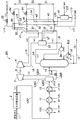
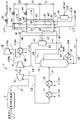
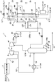
- the block diagram which shows the flow of the liquefaction process in the liquefaction system of the natural gas which concerns on 4th Embodiment The block diagram which shows the flow of the liquefaction process in the liquefaction system of the natural gas which concerns on 5th Embodiment
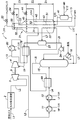
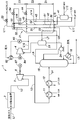
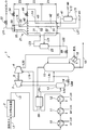
- the block diagram which shows the flow of the liquefaction process in the liquefaction system of the natural gas which concerns on 6th Embodiment The block diagram which shows the flow of the liquefaction process in the liquefaction system of the natural gas which concerns on the 1st modification of 6th Embodiment.
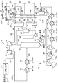
- the block diagram which shows the flow of the liquefaction process in the liquefaction system of the natural gas which concerns on 7th Embodiment The block diagram which shows the flow of the liquefaction process in the liquefaction system of the natural gas which concerns on 8th Embodiment
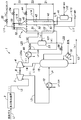
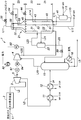
- the block diagram which shows the flow of the liquefaction process in the liquefaction system of the natural gas which concerns on 9th Embodiment The block diagram which shows the flow of the liquefaction process in the liquefaction system of the natural gas which concerns on the 1st modification of 9th Embodiment.
- the block diagram which shows the flow of the liquefaction process in the liquefaction system of the natural gas which concerns on 10th Embodiment The block diagram which shows the flow of the liquefaction process in the liquefaction system of the natural gas which concerns on the 1st modification of 10th Embodiment.
- the block diagram which shows the flow of the liquefaction process in the liquefaction system of the natural gas which concerns on 11th Embodiment The figure which shows the 1st modification of the connection structure of the expander and compressor in the liquefaction system of the natural gas which concerns on this invention.
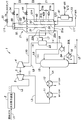
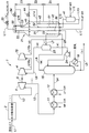
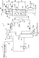
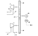
- FIG. 1 is a configuration diagram showing the flow of liquefaction processing in the natural gas liquefaction system according to the first embodiment of the present invention.
- Table 1 shown below is a simulation result related to the liquefaction process in the natural gas liquefaction system according to the first embodiment (the same applies to Tables 2 to 12).
- Table 1 shows an example of the temperature, pressure, flow rate, molar fraction of each component, and the like of natural gas (hereinafter referred to as source gas) to be liquefied in the liquefaction system 1 according to the first embodiment.
- the column (i)-(ix) in Table 1 shows the numerical values at each position of the liquefaction system 1 with the same numbers (i)-(ix) in FIG.
- natural gas containing about 80 to 98 mol% of methane is used as the raw material gas.
- the source gas contains at least one of 0.1 mol% or more of C5 + hydrocarbons and 1 ppm to mol or more of BTX (benzene, toluene, xylene) as a heavy component. Details of components other than methane in the source gas are as shown in Table 1 ((i) column).
- the term “source gas” in the present specification does not mean that the gas is strictly in a gas state, but refers to an object (including during the process) to be liquefied by the liquefaction system 1.
- the raw material gas is supplied to the moisture removing device 2 via the line L1, and the moisture in the raw material gas is removed in order to prevent troubles caused by freezing.
- the raw material gas supplied to the moisture removing device 2 has a temperature of about 20 ° C., a pressure of about 5,830 kPaA, and a flow rate of about 720,000 kg / hr.
- the moisture removing device 2 is composed of a dehydration tower filled with a hygroscopic agent (such as molecular sieve), and dehydrates it so that the moisture in the raw material gas is preferably less than 0.1 ppm mol.
- the moisture removing device 2 other known devices may be adopted as long as the moisture in the raw material gas can be removed to a desired ratio or less.
- the liquefaction system 1 includes a separation facility for separating natural gas condensate and an acid gas removal for removing acid gas components such as carbon dioxide and hydrogen sulfide as a pre-process of the moisture removing device 2. It is possible to provide well-known equipment such as equipment and mercury removal equipment for removing mercury.
- the moisture removing apparatus 2 is usually supplied with a raw material gas from which impurities are removed by each of these facilities.
- the raw material gas supplied to the moisture removing device 2 is preferably less than 50 ppm mol of carbon dioxide (CO 2 ), less than 4 ppm mol of hydrogen sulfide (H 2 S), less than 20 mg / Nm 3 of sulfur, 10 ng / Nm Pre-processed to a mercury below 3 .
- the source of the source gas is not particularly limited.
- a gas obtained from a pressurized state collected from shale gas, tight sand gas, coal bed methane, or the like is used as the source gas. Can be used.
- a method for supplying the raw material gas to the liquefaction system not only supply from a gas field or the like through a pipe but also gas once stored in a storage tank or the like may be supplied.
- the raw material gas from which moisture has been removed in the moisture removing device 2 is sent to the first expander 3 via the line L2.
- the first expander 3 is composed of a turbine device for reducing the pressure of the raw material gas and taking out the power (or energy) based on the expansion force by expanding the flowing raw material gas isentropically. In the expansion process (first expansion process) by the first expander 3, the pressure and temperature of the raw material gas are decreased.
- the first expander 3 has a shaft 5 that is coaxial with the first compressor 4 that will be described in detail later, whereby the power generated by the first expander 3 is used as the power of the first compressor 4. It is possible.
- the rotation speed of the first expander 3 is lower than the rotation speed of the first compressor 4, a speed increaser or the like can be provided between the first expander 3 and the first compressor 4. .
- the temperature of the raw material gas discharged from the first expander 3 is reduced to about 8.3 ° C., and the pressure is reduced to about 4,850 kPaA.
- the pressure of the raw material gas discharged from the first expander 3 is in the range of 3,000 kPaA-5,500 kPaA (30 bara-55 bara), more preferably in the range of 3,500 kPaA-5,000 kPaA (35 bara-50 bara). .
- the raw material gas from the first expander 3 is sent to the cooler 11 via the line L3.
- a cooler 12 is connected to the downstream side of the cooler 11 to constitute a cooler group (first cooler).
- the source gas is sequentially cooled by heat exchange with the refrigerant in the first coolers 11 and 12 (first cooling step).
- the temperature of the raw material gas cooled by the first coolers 11 and 12 is in the temperature range of ⁇ 20 ° C. to ⁇ 50 ° C., more preferably in the temperature range of ⁇ 25 ° C. to ⁇ 35 ° C.
- the outlet temperature of the raw material gas at the first expander 3 is relatively low (for example, about ⁇ 30 ° C.). Therefore, a configuration in which the first coolers 11 and 12 are omitted is also possible.
- the omission of the cooler on the upstream side of the distillation apparatus 15 can be similarly applied to the configurations shown in FIGS. 4 to 26, FIG. 30, FIG.
- a C3-MR (C3-MR: Propane (C3) pre-cooled Mixed Refrigerant) method is adopted, and in the first coolers 11 and 12, the raw material gas is precooled using propane as a refrigerant, The raw material gas is liquefied and supercooled to a very low temperature in a refrigeration cycle using a mixed refrigerant described in detail later.
- the first coolers 11 and 12 use propane refrigerant (C3R) of medium pressure (MP) and low pressure (LP), respectively, and the raw material gas is stepwise (here, 2 stage).
- the first coolers 11 and 12 constitute a part of a known refrigeration cycle including a propane refrigerant compressor, a condenser, and the like.
- the liquefaction system 1 is not limited to the C3-MR system, but a cascade system in which individual refrigeration cycles are configured by a plurality of refrigerants having different boiling points (methane, ethane, propane, etc.), and a mixed refrigerant such as ethane and propane is a precooling process.
- Other known technologies such as the DMR (Double Mixed Refrigerant) method used for the MFC and the MFC (Mixed Fluid Cascade) method that performs heat exchange in stages using mixed refrigerants of different series for each of the precooling, liquefaction, and supercooling cycles This method can be adopted.
- the raw material gas from the cooler 12 is sent to the distillation apparatus 15 via the line L4.
- the pressure of the raw material gas is preferably set to be equal to or lower than the critical pressure of methane and heavy components by expansion in the first expander 3 or the like.
- the distillation apparatus 15 includes a distillation tower having a plurality of shelves inside, and removes heavy components contained in the raw material gas (distillation step).
- the liquid containing heavy components is discharged via a line L5 connected to the bottom of the distillation apparatus 15.
- the liquid containing heavy components discharged from the line L5 to the outside has a temperature of about 177 ° C. and a flow rate of about 20,000 kg / hr.
- “heavy fraction” refers to a high boiling point component such as benzene or C5 + hydrocarbon, which has a relatively high freezing point, but may include C2 + hydrocarbon other than methane.
- the line L5 is provided with a circulation unit including the reboiler 16, and thereby, a part of the liquid discharged from the bottom of the distillation apparatus 15 is vapor (or alternatively) supplied to the reboiler 16 from the outside. After being heated by heat exchange with the oil), it is circulated to the distillation device 15 again.
- the raw material gas delivered to the line L6 has a temperature of about -45.6 ° C. and a pressure of about 4,700 kPaA.
- the raw material gas from which the heavy components have been removed by the distillation apparatus 15 becomes less than 0.1 mol% of C5 +, and less than 1 ppm mol of BTX (benzene, toluene, xylene).
- the source gas is cooled to a temperature of about ⁇ 65.2 ° C. by flowing through the tube circuits 22a and 22b, and then sent from the liquefier 21 to the first gas-liquid separation tank 23 via the line L7.
- the liquefaction device 21 that forms the main heat exchanger of the liquefaction system 1 is a spool winding (Spool) that is housed in a shell in a state in which a heat transfer tube (tube bundle) that flows the raw material gas and refrigerant is wound in a coil shape Wound type heat exchanger.
- Spool spool winding
- the liquefaction device 21 it is located in the lower part (bottom part) where the mixed refrigerant is introduced, and is located in the warm temperature region Z1 having the highest temperature (here, the temperature range) and in the middle part, and is higher than the warm temperature region Z1.
- the warm temperature region Z1 includes a high temperature side warm temperature region Z1a and a low temperature side warm temperature region Z1b.
- the warm temperature zone Z1a on the high temperature side is about ⁇ 35 ° C.
- the warm temperature zone Z1b is about ⁇ 50 ° C. upstream of the source gas and about ⁇ 65 ° C. downstream of the source gas
- the intermediate zone Z2 is about ⁇ 65 ° C. upstream of the source gas and downstream of the source gas.
- the cold temperature region Z3 is set to be about -135 ° C on the upstream side of the raw material gas and about -155 ° C on the downstream side of the raw material gas.
- the upstream and downstream temperatures in each region are not necessarily limited to those shown here.
- the value of each said temperature can be fluctuate
- the first gas-liquid separation tank 23 separates the liquid phase component (condensed component) in the raw material gas, and again distills the liquid such as hydrocarbons constituting the liquid phase component by the reflux pump 24 provided in the line L8. Cycle to 15.
- the raw material gas mainly composed of methane constituting the gas phase component is sent to the first compressor 4 via the line L9.
- the raw material gas sent to the line L8 has a flow rate of about 83,500 kg / hr
- the raw material gas sent to the line L6 has a flow rate of about 780,000 kg / hr.
- the 1st gas-liquid separation tank 23 it can cool using the mixed refrigerant
- the first compressor 4 is a single-stage centrifugal compressor in which an impeller that compresses gas is attached to a shaft 5 that is coaxial with the first expander 3.
- the raw material gas compressed in the compression step (first compression step) by the first compressor 4 is introduced into the liquefaction device 21 via the line L10.
- the raw material gas sent from the first compressor 4 to the line L10 has a temperature of about ⁇ 51 ° C. and a pressure of about 5,500 kPaA.
- the raw material gas introduced into the liquefying device 21 is preferably compressed by the first compressor 4 to a pressure exceeding at least 5,171 kPaA.
- the line L10 is connected to the tube circuit 30 disposed in the warm temperature region Z1b in the liquefying device 21, and the upper end side of the tube circuit 30 is connected to the tube circuit 31 disposed in the intermediate region Z2 and the cold temperature region Z3.
- the raw material gas is liquefied and supercooled through the pipe circuit 31 and the pipe circuit 32, and then sent to a storage LNG tank (not shown) through an expansion valve 33 provided in the line L11.
- the raw material gas after finally passing through the expansion valve 33 has a temperature of about -162 ° C and a pressure of about 120kPaA.
- the raw material gas flowing in the liquefier 21 is cooled using a refrigeration cycle using a mixed refrigerant.
- the mixed refrigerant is a hydrocarbon mixture containing methane, ethane, and propane with nitrogen added thereto. Ingredients can be used.
- the high-pressure (HP) mixed refrigerant (MR) is supplied to the refrigerant separator 41 via the line L12.
- the mixed refrigerant constituting the liquid phase component of the refrigerant separator 41 is introduced into the liquefying device 21 via the line L13, and then pipes disposed in the warm temperature regions Z1a and Z1b respectively upward in the liquefying device 21.
- the circuits 42a and 42b and the tube circuit 43 disposed in the intermediate area Z2 sequentially flow, and further expand through an expansion valve 44 provided in the line L14, and a part thereof is flash-evaporated.
- the mixed refrigerant that has passed through the expansion valve 44 is directed downward from the spray header 45 disposed in the upper portion of the intermediate region Z2 (that is, counterflowed with respect to the flow of the raw material gas in the liquefying device 21). Discharged.
- the mixed refrigerant discharged from the spray header 45 includes an intermediate tube bundle composed of a tube circuit 31, a tube circuit 43, and a tube circuit 52 described later, and a tube disposed in the warm temperature region Z1.
- the circuits 22a and 22b, the tube circuit 30, the tube circuits 42a and 42b, and the lower tube bundle constituted by the tube circuits 51a and 51b described later flow respectively downward while exchanging heat.
- the mixed refrigerant constituting the gas phase component of the refrigerant separator 41 is introduced into the liquefying device 21 via the line L15, and then disposed upward in the liquefying device 21 in the warm temperature regions Z1a and Z1b.
- the mixed refrigerant that has passed through the expansion valve 54 is cooled to a temperature lower than the boiling point of methane (here, about ⁇ 167 ° C.), and is directed downward (ie, liquefied) from the spray header 55 disposed at the upper part of the cold temperature zone Z3.
- the gas is discharged so as to be countercurrent to the flow of the source gas in the apparatus 21.
- the mixed refrigerant discharged from the spray header 55 flows downward while exchanging heat with the upper tube bundle constituted by the tube circuit 32 and the tube circuit 53 arranged in the cold temperature region Z3, and further from the spray header 45 located below.
- the intermediate pipe bundle constituted by the pipe circuit 31, the pipe circuit 43, and the pipe circuit 52 arranged in the intermediate area Z2, and the pipe circuit 22a arranged in the warm temperature area Z1 , 22b, the tube circuit 30, the tube circuits 42a and 42b, and the lower tube bundle composed of tube circuits 51a and 51b described later, respectively, and flows downward while exchanging heat.
- the mixed refrigerant discharged from the spray header 45 and the spray header 55 is finally discharged as a low-pressure (LP) mixed refrigerant (MP) gas through a line L17 connected to the bottom of the liquefying device 21.
- the equipment related to the mixed refrigerant (refrigerant separator 41 and the like) provided in the above-described liquefying device 21 constitutes a part of a refrigeration cycle for a mixed refrigerant having a well-known configuration not shown here, and the mixed refrigerant from the line L17 is Then, the refrigerant is circulated to the refrigerant separator 41 through the line L12 again through a compressor, a condenser, and the like.
- the raw material gas introduced into the liquefaction system 1 is effectively liquefied through an expansion process, a cooling process, a distillation process, a compression process, a liquefaction process, and the like.
- a liquefaction system 1 can be applied to, for example, a base load liquefaction base for generating liquefied natural gas (LNG) mainly composed of methane from a raw material gas collected from a gas field or the like.
- LNG liquefied natural gas
- First and second reference examples 2 and 3 show the flow of liquefaction processing in a conventional natural gas liquefaction system as first and second reference examples corresponding to the first embodiment of the present invention, respectively.
- the same reference numerals are given to the components corresponding to the liquefaction system 1 according to the first embodiment.
- Table 2 and Table 3 as in Table 1, the temperature, pressure, flow rate, and mole fraction of each component of the raw material gas in the liquefaction systems 101 and 201 as the first and second reference examples, respectively.
- An example is shown.
- the liquefaction system 201 of the second reference example is configured based on the conventional technique of the above-mentioned Patent Document 1 (US Pat. No. 4,065,278).
- the first expander 3 and the first compressor 4 in the liquefaction system 1 of the first embodiment described above are not provided, and the moisture removing device 2 is not provided.
- a cooler 11 and a cooler 12 are sequentially connected to the downstream side of the cooler 110 to form a cooler group, and the raw material gas is exchanged by heat exchange with the refrigerant in the three coolers 110, 11, and 12. Sequentially cooled.
- the coolers 110, 11, and 12 use high-pressure (HP), medium-pressure (MP), and low-pressure (LP) propane refrigerants, respectively, and the raw material gas is stepwise (here, Then, it is cooled in three stages.
- the raw material gas delivered from the most downstream cooler 12 has a temperature of about ⁇ 34.5 ° C. and a pressure of about 5,680 kPaA.
- the raw material gas is decompressed by expansion in the expansion valve 113 provided in the line L4 and then introduced into the distillation apparatus 15.
- the raw material gas which has methane which comprises a gaseous phase component in the 1st gas-liquid separation tank 23 as a main component is the pipe circuit arrange
- the raw material gas sent from the first gas-liquid separation tank 23 to the line L102 has a temperature of about ⁇ 65.3 ° C. and a pressure of about 4,400 kPaA.
- the liquefaction system 201 of the second reference example is an improvement of the liquefaction system 101 of the first reference example, and is provided with an expander 3 and a compressor 4.
- the expander 3 is different from the first expander 3 of the liquefaction system 1 in the first embodiment described above, and is a cooler group (here, three coolers 110, 11, and 12). It is arranged on the downstream side.
- the raw material gas sent from the cooler 12 is sent to the separator 213 via the line L202 to be gas-liquid separated.
- the raw material gas constituting the gas phase component in the separator 213 is sent to the expander 3 via the line L203, expanded in the expander 3, and then sent to the distillation apparatus 15 via the line L204.
- the liquid constituting the liquid phase component in the separator 213 is sent to a line L205 in which the expansion valve 214 is provided.
- the liquid is expanded by the expansion valve 214 and then sent to the distillation apparatus 15 through the line L204 together with the raw material gas from the expander 3.
- the configuration downstream of the distillation apparatus 15 is substantially the same as in the first embodiment, but the raw material gas sent from the compressor 4 to the line L10 has a temperature of about -54.7 ° C.
- the pressure is about 5,120 kPaA.
- the first expander 3 is disposed upstream of the first coolers 11 and 12. Therefore, as compared with the case where the expander 3 is arranged downstream of the coolers 110, 11, 12 as in the liquefaction system 201 of the second reference example, a larger temperature is obtained by expanding the higher temperature / high pressure raw material gas. Power can be generated. As a result, the first compressor 4 can be driven more effectively (that is, the discharge pressure of the first compressor 4 can be increased), the pressure of the raw material gas introduced into the liquefying device 21 is increased, and the liquefying device 21 is increased. There is an advantage that the efficiency of the liquefaction treatment can be increased.
- the temperature of the raw material gas decreases due to the expansion in the first expander 3 by disposing the first expander 3 on the upstream side of the cooler group (first coolers 11 and 12). Therefore, there is also an advantage that the cooling capacity of the cooler group can be reduced (that is, the cooler 110 in the second reference example is omitted). Furthermore, in the liquefaction system 1, it is possible to omit a gas-liquid separation device (separator 213) for separating (removing) the condensed components in the raw material gas between the cooler group and the expander 3.
- FIG. 4 is a configuration diagram showing the flow of the liquefaction process in the natural gas liquefaction system according to the first modification of the first embodiment of the present invention.
- symbol is attached
- a cascade method using methane and ethylene as refrigerant is adopted, and instead of the spool-winding heat exchanger (liquefaction device 21) in the first embodiment described above, plate fin type heat is used.
- a methane heat exchanger 21a and an ethylene heat exchanger 21b made of an exchanger are provided as main heat exchangers.
- the methane heat exchanger 21a has a warm temperature region in which a first heat transfer section 61 into which a high-pressure (HP) methane refrigerant (C1R) is introduced and a medium-pressure (MP) methane refrigerant is introduced.
- An intermediate region in which the second heat transfer unit 62 is provided and a cold / hot region in which the third heat transfer unit 63 into which the low-pressure (LP) methane refrigerant is introduced are provided.
- the ethylene heat exchanger 21b has a warm temperature region in which a fourth heat transfer section 64 into which a high-pressure (HP) ethylene refrigerant (C2R) is introduced and a medium-pressure (MP) ethylene refrigerant is introduced.
- An intermediate region in which the fifth heat transfer unit 65 is provided and a cold temperature region in which the sixth heat transfer unit 66 into which low-pressure (LP) ethylene refrigerant is introduced are provided.
- the raw material gas separated as the column top distillate in the distillation apparatus 15 is once introduced into the liquefaction apparatus 21 via the line L6, and is disposed from the warm temperature region to the intermediate region in the ethylene heat exchanger 21b. It is cooled in the heat transfer section 22. Moreover, the raw material gas compressed in the 1st compressor 4 is sent to the ethylene heat exchanger 21b via the line L10. The raw material gas flowing through the line L10 is introduced into the eighth heat transfer section 67 arranged from the intermediate region to the cold temperature region in the ethylene heat exchanger 21b, and is cooled stepwise in the intermediate region and the cold temperature region.
- the raw material gas sent from the ethylene heat exchanger 21b is further introduced into the ninth heat transfer section 68 arranged from the warm temperature region to the cold temperature region in the methane heat exchanger 21a, and the warm temperature region, intermediate Cooling stepwise in the region and in the cold region.
- the connection position of the line L10 to the main heat exchanger (here, to the ethylene heat exchanger 21b)
- the introduction position to the heat exchanger is changed according to the temperature level (that is, the temperature level of the raw material gas and the introduction position thereof).
- FIG.5 is configuration diagrams showing the flow of the liquefaction process in the natural gas liquefaction system according to the second, third and fourth modifications of the first embodiment of the present invention, respectively.
- symbol is attached
- a heat exchanger 69 is provided between the line L4 and the line L9.
- the source gas flowing through the line L9 separated as the gas phase component in the first gas-liquid separation tank 23 is heated by heat exchange with the source gas flowing through the line L4 introduced from the cooler 12 to the distillation apparatus 15.
- the raw material gas compressed by the first compressor 4 is introduced into the liquefaction device 21 via the line L10.
- the downstream side of the line L10 is connected to the tube circuit 30 disposed in the warm temperature region Z1 having the highest temperature in the liquefaction device 21.
- the tube circuit 30 constitutes a tube bundle disposed in the warm temperature region Z1 together with the tube circuit 22 into which the overhead product of the distillation apparatus 15 is introduced, the tube circuit 42 through which the mixed refrigerant flows, and the tube circuit 51.
- the raw material gas is exchanged by heat exchange in the heat exchanger 69.
- the temperature can be increased appropriately. That is, in the second modification, the temperature of the raw material gas in the line L10 after compression can be brought close to the temperature of the introduction position (pipe circuit 30) in the liquefying device 21 (preferably within 10 ° C.), and as a result It is possible to reduce the thermal load on the liquefying device 21 (suppress the generation of thermal stress and the like).
- the raw material gas heated by the heat exchanger 69 is introduced into the liquefying device 21 without passing through the first compressor 4 or the like, and thus the raw material gas at the time of introduction into the liquefier 21 is used. There is an advantage that it is easy to control the temperature.
- the heat exchanger 69 is provided between the line L4 and the line L6.
- the raw material gas flowing through the line L6 separated from the distillation apparatus 15 as a column top distillate is heated by heat exchange with the raw material gas flowing through the line L4 and then introduced into the liquefying device 21 (pipe circuit 22). Is done.
- natural gas (lean gas) having a relatively small heavy content (higher hydrocarbon content) as shown in Table 1 is used as the raw material gas, and the raw material gas flowing through the line L6 after distillation is used. Even when the temperature level can be lower than the appropriate range, the temperature of the source gas can be appropriately increased by heat exchange in the heat exchanger 69.
- FIG. 8 is a block diagram which shows the flow of the liquefaction process in the liquefaction system of the natural gas which concerns on the 5th modification of 1st Embodiment of this invention.
- symbol is attached
- This fifth modification has a configuration similar to that of the above-described fourth modification, but a heat exchanger 79 is further provided between the line L9 and the line L10, and a low pressure (LP) is provided on the line L10.
- a fifth cooler 80 using propane refrigerant (C3R) is further provided. Thereby, after the raw material gas sent out from the first compressor 4 is cooled by the fifth cooler 80 and further cooled by heat exchange with the raw material gas flowing through the line L9 toward the first compressor 4. It is introduced into the liquefaction device 21.
- the downstream side of the line L10 is connected to the tube circuit 31 disposed in the intermediate region Z2.
- the raw material gas sent from the first compressor 4 can be introduced into the intermediate region Z2.
- the tube bundle in the warm temperature region Z1 is provided by the three tube circuits 22, the tube circuit 42, and the tube circuit 51
- the tube bundle in the intermediate region Z2 is provided by the three tube circuits 31, the tube circuit 43, and the tube circuit 52, respectively. It can be configured.
- the liquefying device 21 is configured by a spool-type heat exchanger, the arrangement of the tube circuits in the warm temperature region Z1 and the warm temperature region Z1 (each There is an advantage that the liquefaction apparatus 21 can be prevented from being enlarged.
- the propane refrigerant used in the first coolers 11 and 12 is used, but not limited to this, an air-cooled or water-cooled cooler may be used.
- FIG. 9 is a configuration diagram showing the flow of the liquefaction process in the natural gas liquefaction system according to the sixth modification of the first embodiment of the present invention.
- Table 4 shows an example of the temperature, pressure, flow rate, and mole fraction of each component of the raw material gas in the liquefaction system of the sixth modified example.
- Table 5 shows an example of the refrigerant temperature, pressure, flow rate, molar fraction of each component, and the like in the mixed refrigerant refrigeration cycle used in the liquefaction system.
- symbol is attached
- the liquefaction system 1 according to the sixth modified example has substantially the same configuration as the second to fourth modified examples described above except for the difference in the composition of the raw material gas and the difference in the presence or absence of the heat exchanger 69. have.
- the line L10 is connected to the tube circuit 31 arranged in the intermediate region Z2 in the liquefying device 21.
- FIG. 9 shows a configuration of a mixed refrigerant type refrigeration cycle system 70 included in the liquefaction system 1.
- natural gas (rich gas) having a relatively large heavy component (higher hydrocarbon content) as shown in Table 4 is used as the raw material gas.
- the column top distillate of the distillation apparatus 15 is set to a lower pressure (about 3,300 kPaA) than in the case of the first embodiment described above.
- the recovery of the natural gas liquid (Natural Gas Liquid) via the line L5 at the bottom of the distillation apparatus 15 is highly efficient (for example, propane (Approx. 89%, butane is recovered about 100%).
- the low-pressure (about 320 kPaA) mixed refrigerant discharged from the liquefying device 21 via the line L17 is pressurized by the first refrigerant compressor 17, then cooled by the first intercooler 27, and continued.
- the mixed refrigerant After being boosted by the second refrigerant compressor 18 in the second stage, it is cooled by the second intercooler 28, and after being boosted by the third refrigerant compressor 19 in the third stage, it is cooled by the third intercooler 29.
- the mixed refrigerant is further cooled by first to fourth refrigerant coolers 34-37 constituting a series of cooler groups, and then introduced into the refrigerant separator 41 via a line L12.
- the mixed refrigerant is cooled stepwise by heat exchange with propane refrigerants of ultra high pressure (HHP), high pressure (HP), medium pressure (MP) and low pressure (LP), respectively. Is done.
- HPHP ultra high pressure
- HP high pressure
- MP medium pressure
- LP low pressure
- the refrigeration cycle system 70 includes a propane precooling system facility (not shown) for cooling the raw material gas before being introduced into the liquefying device 21, and includes first to fourth refrigerants.
- the propane precooling system propane refrigerant is used for cooling the mixed refrigerant in the coolers 34-37.
- Such a refrigeration cycle system 70 can be similarly applied to other embodiments (including other modified examples).
- FIG. 10 is a block diagram which shows the flow of the liquefaction process in the liquefaction system of the natural gas which concerns on the 7th modification of 1st Embodiment of this invention.
- Table 6 shows an example of the temperature, pressure, flow rate, and mole fraction of each component of the raw material gas in the liquefaction system of the seventh modified example.
- symbol is attached
- a rich gas is used as the raw material gas as in the sixth modified example described above, and in particular, a configuration suitable for a case where the critical pressure becomes relatively high depending on the composition of the raw material gas is shown.
- a third cooler 86 using a low-pressure (LP) propane refrigerant (C 3 R) is provided in a line L 6 between the distillation apparatus 15 and the first gas-liquid separation tank 23, and the first compressor 4 Similarly, a second cooler 85 using a low-pressure propane refrigerant is provided in the line L10 to the liquefying device 21.
- LP low-pressure propane refrigerant
- the raw material gas flowing in the line L6 from the distillation apparatus 15 is introduced into the first gas-liquid separation tank 23 after being cooled by the third cooler 86. That is, in the seventh modification, it is not necessary to cool the source gas introduced into the first gas-liquid separation tank 23 by the liquefaction device 21 (pipe circuit 22) as in the sixth modification described above. There is an advantage that the load of the liquefaction treatment can be reduced.
- the raw material gas flowing through the line L10 from the first compressor 4 is introduced into the liquefying device 21 after being cooled by the second cooler 85.
- the downstream side of the line L10 is connected to the tube circuit 30 disposed in the warm temperature region Z1 having the highest temperature in the liquefying device 21. That is, in the seventh modification, even when the temperature level of the source gas exceeds an appropriate level due to the pressure increase of the source gas by the first compressor 4, the temperature of the source gas is liquefied by cooling with the second cooler 85.
- the thermal load of the liquefying device 21 can be reduced (the generation of thermal stress and the like can be suppressed).
- FIG. 33 is a block diagram showing the flow of liquefaction processing in the natural gas liquefaction system according to the eighth modification of the first embodiment of the present invention.
- symbol is attached
- This eighth modification has a configuration similar to that of the fifth modification described above, but the fifth cooler 80 in the fifth modification is omitted, and the line L6 from the distillation apparatus 15 and the first compressor are omitted.
- a heat exchanger 100 is further provided between the line 4 and the line L10.
- the raw material gas sent from the first compressor 4 to the line L10 is not cooled by the fifth cooler 80, but the raw material gas sent from the distillation device 15 to the line L6 (column top distillate).
- the heat is introduced into the heat exchanger 79 as in the fifth modification.
- the raw material gas from the distillation apparatus 15 is once introduced into the liquefaction apparatus 21 via the line L6 after heat exchange, and is cooled in the pipe circuit 22.
- the cooling of the source gas by the fifth cooler 80 in the fifth embodiment can be supplemented by heat exchange in the heat exchanger 100 (the fifth cooler 80 is omitted). it can.
- the heat exchanger 69 in the fifth modified example is also omitted.
- the heat exchanger 69 is provided in the same manner as in the fifth modified example, and the distillation apparatus 15 is connected to the line L6.
- the source gas to be sent may be introduced into the heat exchanger 100 via the heat exchanger 69.
- FIG. 11 is a block diagram showing the flow of liquefaction processing in the natural gas liquefaction system according to the second embodiment of the present invention.
- Table 7 shows an example of the temperature, pressure, flow rate, and mole fraction of each component in the liquefaction system 1 according to the second embodiment.
- symbol is attached
- a fourth compressor 71 and a fourth cooler 72 for further gas supply are provided on the upstream side of the line L1 for supplying the raw material gas to the moisture removing device 2.
- the source gas supplied from the line L18 is pressurized in the fourth compressor 71 for gas supply, and after being cooled by the fourth cooler 72 provided on the downstream side, the moisture is removed. Supplied to the device 2.
- a liquefaction system 1 of the second embodiment even when the pressure of the source gas supplied to the liquefaction system 1 is relatively low, the source gas can be boosted to a desired pressure by the fourth compressor 71 for gas supply. As a result, the pressure value of the raw material gas sent from the first compressor 4 to the liquefaction device 21 can be kept relatively high (here, a pressure of about 6,800 kPaA).
- a liquefaction system 1 is particularly suitable for processing raw material gas from a relatively low pressure source such as shale gas.
- the temperature level of the raw material gas sent from the first compressor 4 to the liquefaction device 21 can be maintained relatively high by providing the fourth compressor 71 for gas supply.
- the line L10 is a tube circuit 30 arranged in a warm temperature region Z1 on the high temperature side in the liquefaction device 21 (that is, a mixed refrigerant introduction side having a temperature level equivalent to the raw material gas introduced into the liquefaction device 21). It is connected to the. Thereafter, the raw material gas is liquefied and supercooled from the tube circuit 30 through the tube circuit 31 disposed in the intermediate region Z2 and the tube circuit 32 disposed in the cold region Z3.
- region Z1 of the liquefying apparatus 21 can be suitably employ
- the second cooler 85 is installed as in FIG.
- the load on the liquefying device 21 can be reduced.
- FIG. 12 is a block diagram which shows the flow of the liquefaction process in the liquefaction system of the natural gas which concerns on 3rd Embodiment of this invention.
- Table 8 shows an example of the temperature, pressure, flow rate, and mole fraction of each component in the liquefaction system 1 according to the third embodiment.
- symbol is attached
- a second compressor 75 for further boosting is provided downstream of the first compressor 4. That is, the source gas is boosted in the first compressor 4 and then sent to the second compressor 75 via the line L10a, where it is further boosted (here, a pressure of about 7,000 kPaA), and then the line L10b Is introduced into the liquefaction device 21.
- the inside of the liquefying apparatus 21 has the same configuration as that of the second embodiment, and the line L10b is connected to the tube circuit 30 disposed in the warm temperature region Z1 in the liquefying apparatus 21.
- the second compressor 75 is further provided downstream of the first compressor 4, the second compressor 75 is introduced into the liquefaction device 21 via the line L10b.
- the pressure of the raw material gas can be further increased (for example, up to a pressure of about 7,000 to 10,000 kPaA), and the efficiency of the liquefaction treatment is improved.
- FIG. 13 is a block diagram which shows the flow of the liquefaction process in the liquefaction system of the natural gas which concerns on the modification of 3rd Embodiment of this invention.
- symbol is attached
- the second compressor 75 is driven by a motor (first motor) 81, and the speed of the motor 81 is controlled by a controller 82 that performs variable frequency driving. Electric power is supplied to the motor 81 from the outside.
- the speed of the motor 81 (that is, the operation of the second compressor 75) is based on the detected value of the pressure gauge 83 provided in the line L10b, and the pressure of the raw material gas introduced into the liquefier 21 is constant (predetermined target range). ).
- the pressure of the raw material gas introduced into the liquefying device 21 can be stably increased by the second compressor 75, and as a result, the temperature of the raw material gas is also stably maintained in an appropriate range, The liquefaction process at 21 can be performed efficiently and stably.
- FIG. 14 is a block diagram which shows the flow of the liquefaction process in the liquefaction system of the natural gas which concerns on 4th Embodiment of this invention.
- Table 9 shows an example of the temperature, pressure, flow rate, and mole fraction of each component in the liquefaction system 1 according to the fourth embodiment.
- symbol is attached
- a further second cooler 85 using a low-pressure (LP) propane refrigerant (C3R) is provided downstream of the second compressor 75 shown in the third embodiment of FIG. It has been.
- the raw material gas sent from the first compressor 4 to the line L10a is boosted in the second compressor 75 and then sent to the second cooler 85 via the line L10b. After further cooling there, the raw material gas passes through the line L10c. And introduced into the liquefaction device 21.
- the inside of the liquefying device 21 has the same configuration as that of the third embodiment, and the line L10c is connected to the tube circuit 30 disposed in the warm temperature region Z1 in the liquefying device 21.
- the raw material gas can be brought close to the temperature level of the warm temperature region Z1 of the liquefying device 21 by cooling the raw material gas using a low-pressure propane refrigerant.
- the thermal load on the liquefaction device 21 can be reduced and the efficiency of the liquefaction process can be increased.
- the second cooler 85 that is, a propane refrigerant having higher cooling ability than water or air
- the temperature becomes lower (0 ° C.).
- Table 10 shows a comparison of power required for the compressors in the first to fourth embodiments and the first and second reference examples. As shown in Table 10, it can be seen that the total power and specific output of the first to fourth embodiments are reduced with respect to the first and second reference examples (prior art).
- FIG. 15 is a block diagram which shows the flow of the liquefaction process in the liquefaction system of the natural gas which concerns on 5th Embodiment of this invention.
- symbol is attached
- the first expander 3 and the first compressor 4 are not mechanically connected, and both are electrically connected. It is connected to the.
- a power generator 87 is connected to the first expander 3, and the power generated by the first expander 3 is converted into electric power by the power generator 87.
- the electric power generated by the power generator 87 is supplied to the motor 84 that drives the first compressor 4 (that is, the motive power generated in the first expander 3 is used by the first compressor 4).
- the power supplied from the power generation device 87 may be at least part of the power for driving the motor 84. When the power is insufficient, power is separately supplied from an external power supply source (not shown).
- the first expander 3 and the first compressor 4 are electrically connected. Therefore, when the first expander 3 and the first compressor 4 are started or stopped. There is an advantage that the degree of freedom of operation in (i.e., it becomes possible to operate independently).
- FIG. 16 is a block diagram which shows the flow of the liquefaction process in the liquefaction system of the natural gas which concerns on 6th Embodiment of this invention.
- the liquefaction system 1 shown in FIG. 16 about the component similar to the liquefaction system 1 which concerns on 1st to 5th embodiment, each is attached
- a rich gas containing about 88 mol% of methane is used as a source gas (the same applies to the modified example of the sixth embodiment and the seventh and eighth embodiments).
- the raw material gas separated as the top distillate of the distillation apparatus 15 is directly introduced into the first compressor 4 via the line L19 and compressed. Thereafter, the raw material gas is sent from the first compressor 4 via the line L20 to the pipe circuit 22 disposed in the warm temperature zone Z1 and is preliminarily cooled, and then further through the line L21. It is introduced into the liquid separation tank 23.
- the first gas-liquid separation tank 23 separates the liquid phase component (condensed component) in the raw material gas, and the liquid such as hydrocarbons constituting the liquid phase component again passes through the expansion valve 89 provided in the line L22. Circulate to the distillation unit 15. On the other hand, in the first gas-liquid separation tank 23, the raw material gas mainly composed of methane constituting the gas phase component is sent to the tube circuit 31 in the liquefier 21 via the line L23.
- the first gas-liquid separation tank 23 is provided on the downstream side of the first compressor 4, and the raw material gas from the first compressor 4 is disposed in the warm temperature zone Z1. Since the first gas-liquid separation tank 23 is introduced through the tube circuit 22, the temperature level of the raw material gas can be brought close to the temperature level of the warm temperature region Z1 of the liquefying device 21, and the raw material gas can be supplied to the liquefying device 21.
- the temperature of the raw material gas The level can be easily brought close to the temperature level of the intermediate region Z2 of the liquefying device 21. Furthermore, since the source gas from the first gas-liquid separation tank 23 can be pumped by the first compressor 4, a circulation path (from the first gas-liquid separation tank 23 to the distillation apparatus 15 in the first embodiment described above) ( There is also an advantage that the reflux pump 24 provided in the line L21) can be omitted.
- the column top distillate of the distillation apparatus 15 is once cooled by the liquefaction apparatus 21, and then gas-liquid separated in the first gas-liquid separation tank 23, and the gas phase component is first compressed.
- the temperature of the raw material gas rises in the first compressor 4 before the liquefaction device 21.
- the temperature level of the raw material gas is out of the appropriate range for introduction into the liquefying device 21, thereby increasing the thermal load on the liquefying device 21.
- a problem can be solved by changing the introduction position of the raw material gas to the liquefying device 21, but a spool-type heat exchanger or the like in which the change of the introduction position of the raw material gas is not easy is used as the main heat exchanger. If used, it may not be possible due to the structure of the heat exchanger. Therefore, as in the present embodiment, the raw material gas separated as the top distillate of the distillation apparatus 15 is directly introduced into the first compressor 4 via the line L19 and compressed, and the first compression is performed.
- the raw material gas compressed by the machine 4 is cooled in the warm temperature region Z1 of the liquefier 21, and then gas-liquid separated in the first gas-liquid separation tank 23, and the gas phase component is separated in the intermediate region Z2 (warm temperature region) of the liquefaction device 21.
- Z1 warm temperature region
- Z2 warm temperature region
- FIG. 17 is a block diagram which shows the flow of the liquefaction process in the liquefaction system of the natural gas which concerns on the modification of 6th Embodiment of this invention.
- Table 11 shows an example of the temperature, pressure, flow rate, and mole fraction of each component of the raw material gas in the liquefaction system 1 according to the modification of the sixth embodiment.
- symbol is attached
- the first cooler 11 shown in the sixth embodiment of FIG. 16 is omitted, while a second low pressure propane is used as a refrigerant downstream of the first compressor 4.
- a cooler 85 is provided. After the raw material gas is sent from the first compressor 4 to the second cooler 85 via the line L20a and cooled, the raw material gas passes through the line L20b to the tube circuit 22 disposed in the warm temperature region Z1 of the liquefier 21. Then, it is further cooled, and then introduced into the first gas-liquid separation tank 23 via the line L21.
- FIG. 18 and 19 are configuration diagrams showing the flow of liquefaction processing in a natural gas liquefaction system according to second and third modifications of the sixth embodiment of the present invention, respectively.
- the liquefaction system 1 shown in FIG.18 and FIG.19 about the component similar to the liquefaction system 1 which concerns on 6th Embodiment (another modification is included), each is attached
- a heat exchanger 69 is provided between the line L4 and the line L19.
- the raw material gas flowing through the line L19 separated as the top distillate of the distillation apparatus 15 is heated by heat exchange with the raw material gas flowing through the line L4 introduced into the distillation apparatus 15 from the cooler 12 Introduced into the first compressor 4.
- the raw material gas compressed by the first compressor 4 is introduced into the liquefaction device 21 via the line L20.
- the downstream side of the line L20 is connected to a pipe circuit 22 disposed in the warm temperature region Z1 having the highest temperature in the liquefaction device 21.
- the raw material gas is exchanged by heat exchange in the heat exchanger 69.
- the temperature can be increased appropriately. That is, in the second modification, the temperature of the raw material gas in the line L20 after compression can be brought close to the temperature of the introduction position (pipe circuit 22) in the liquefying device 21 (preferably within 10 ° C.), and as a result It is possible to reduce the thermal load on the liquefying device 21 (suppress the generation of thermal stress and the like).
- the heat exchanger 69 is provided between the line L4 and the line L20.
- the raw material gas flowing through the line L20 sent from the first compressor 4 is heated by heat exchange with the raw material gas flowing through the line L4, and then the tube circuit 22 disposed in the warm temperature region Z1 of the liquefying device 21.
- the raw material gas heated by the heat exchanger 69 is introduced into the liquefaction device 21 without passing through the first compressor 4 or the like, so the temperature of the raw material gas at the time of introduction into the liquefaction device 21 is increased. There is an advantage that it is easy to control.
- FIG. 20 is a block diagram which shows the flow of the liquefaction process in the liquefaction system of the natural gas which concerns on the 4th modification of 6th Embodiment of this invention.
- Table 12 shows an example of the temperature, pressure, flow rate, and mole fraction of each component of the raw material gas in the liquefaction system of the fourth modified example.
- symbol is attached
- a gas having a lower pressure than that of the above-described sixth embodiment is used as the source gas, and particularly suitable when the critical pressure is relatively high due to the composition of the source gas containing nitrogen and heavy components.
- the structure is shown.
- the raw material gas is sent from the first compressor 4 to the second cooler 85 via the line L20a and cooled, and then the line L20b is set. Through the first gas-liquid separation tank 23.
- the line L20b is connected to the first gas-liquid separation tank 23 without going through the liquefying device 21, and the source gas constituting the gas phase component in the first gas-liquid separation tank 23 is the line It is sent to the tube circuit 30 disposed in the warm temperature zone Z1 having the highest temperature in the liquefaction device 21 via L23.
- the fourth modification it is not necessary to cool the source gas introduced into the first gas-liquid separation tank 23 by the liquefier 21 (introduction into the tube circuit 22) as in the first modification described above. There is an advantage that the load of the liquefaction treatment of the liquefying device 21 can be reduced.
- FIG. 21 is a configuration diagram showing the flow of liquefaction processing in the natural gas liquefaction system according to the seventh embodiment of the present invention.
- symbol is attached
- the liquefaction system 1 of the seventh embodiment has a configuration similar to that of the sixth embodiment, but two expanders (a first expander 3a and a second expander 3b) are arranged in parallel on the downstream side of the moisture removing device 2. It differs from the case of the sixth embodiment in that it is arranged at the point. Further, in the seventh embodiment, two compressors (first compressor 4a and third compressor 4b) having shafts 5a and 5b coaxial with the first and second expanders 3a and 3b, respectively, are provided. Yes.
- the raw material gas from the moisture removing device 2 is sent to the first and second expanders 3a and 3b via lines L2a and L2b, respectively.
- the raw material gases from the first and second expanders 3a and 3b are sent to the cooler 12 through lines L3a, L3b and L3.
- LP low-pressure propane refrigerant
- the raw material gas separated as the column top distillate of the distillation apparatus 15 is sent to the third compressor 4b via the line L19 and compressed. Thereafter, the raw material gas is sent from the third compressor 4b to the pipe circuit 22 disposed in the warm temperature zone Z1 via the line L20 and cooled, and then further, the first gas-liquid separation tank via the line L21. 23.
- the first gas-liquid separation tank 23 separates the liquid phase component (condensed component) in the raw material gas, and the liquid such as hydrocarbons constituting the liquid phase component again passes through the expansion valve 89 provided in the line L22. Circulate to the distillation unit 15.
- the raw material gas mainly composed of methane constituting the gas phase component is sent to the first compressor 4a via the line L24 and compressed. Thereafter, the raw material gas is introduced from the first compressor 4a into the tube circuit 30 disposed in the warm temperature region Z1 in the liquefier 21 through the line L25.
- the pressure of the raw material gas supplied to the liquefaction system 1 is relatively high, Moreover, even when the critical pressure is low, the source gas can be appropriately boosted (that is, the source gas introduced into the distillation apparatus 15 can be prevented from exceeding the critical pressure) by the plurality of compressors 4a and 4b.
- FIG. 22 is a configuration diagram showing the flow of liquefaction processing in the natural gas liquefaction system according to the eighth embodiment of the present invention.
- symbol is attached
- the liquefaction system 1 of the eighth embodiment has a configuration similar to that of the sixth or seventh embodiment, but two first expanders 3a and 3b are arranged in series, and the first expander 3a. 3b differs from those embodiments in that a separator 91 is disposed between 3b.
- the raw material gas from the moisture removing device 2 is sent to the first expander 3a via the line L2, expanded there, and then introduced into the separator 91 via the line L3.
- the separator 91 the raw material gas separated as the gas phase component is sent to the second expander 3b via the line L26, expands there, and then sent to the cooler 12 via the line L27.
- the separator 91 separates the liquid phase component (condensed component) in the raw material gas, and the liquid constituting the liquid phase component is sent to the cooler 12 via the expansion valve 92 provided in the line L28.
- the eighth embodiment as in the case of the seventh embodiment described above, a plurality of compressions are performed even when the pressure of the raw material gas supplied to the liquefaction system 1 is relatively high and the critical pressure is low. There is an advantage that the source gas can be appropriately boosted by the machines 4a and 4b.
- FIGS. 23 and 24 are configuration diagrams showing the flow of liquefaction processing in the natural gas liquefaction system according to the first and second modifications of the eighth embodiment of the present invention, respectively.
- symbol is attached
- the liquefaction system 1 according to the first modification has a configuration substantially similar to that of the eighth embodiment.
- a heat exchanger 69 is provided between the line L4 and the line L19. Is provided.
- the raw material gas flowing through the line L19 separated as the top distillate of the distillation apparatus 15 is heated by heat exchange with the raw material gas flowing through the line L4 introduced into the distillation apparatus 15 from the cooler 12 It is introduced into the third compressor 4b.
- the raw material gas is exchanged by heat exchange in the heat exchanger 69. The temperature can be increased appropriately.
- the liquefaction system 1 according to the second modification has a configuration substantially similar to that of the eighth embodiment, but in the second modification, a heat exchanger is provided between the line L4 and the line L25. 69 is provided. Thereby, the raw material gas flowing through the line L25 sent from the first compressor 4a is heated by heat exchange with the raw material gas flowing through the line L4 introduced from the cooler 12 into the distillation apparatus 15, and then inside the liquefaction device 21. Is introduced into the tube circuit 30 disposed in the warm temperature region Z1.
- the source gas heated by the heat exchanger 69 is introduced into the liquefaction device 21 without passing through the first compressor 4 or the like, and therefore the temperature of the source gas at the time of introduction into the liquefaction device 21 is increased. There is an advantage that it is easy to control.
- FIG. 25 is a configuration diagram showing the flow of liquefaction processing in the natural gas liquefaction system according to the ninth embodiment of the present invention.
- symbol is attached
- the critical pressure of the raw material gas is relatively low, and the first gas-liquid separation tank from the first compressor 4 This is useful when the pressure of the raw material gas delivered toward the pressure 23 becomes higher than the critical pressure (that is, the first gas-liquid separation tank 23 does not function properly).
- the raw material gas is sent from the first compressor 4 to the second cooler 85 via the line L20a and cooled, and then disposed in the warm temperature region Z1 of the liquefaction device 21 via the line L20b. Sent to the pipe circuit 22 and further cooled.
- the raw material gas flowing in the line L21 is again distilled through the line L22 and the line L23 branched up and down, and again through the expansion valve 89 provided in the line L22 partially extending downward from the branch part.
- the remaining raw material gas is introduced into the tube circuit 31 disposed in the intermediate region Z2 of the liquefying device 21 via a line L23 extending upward from the branching portion.
- FIG. 26 is a block diagram showing the flow of liquefaction processing in a natural gas liquefaction system according to a modification of the ninth embodiment of the present invention.
- symbol is attached
- the second gas-liquid separation tank 25 into which the raw material gas flowing through the line L22 is introduced via the expansion valve 89 is provided.
- the second gas-liquid separation tank 25 separates the liquid phase component in the raw material gas and circulates the liquid phase component to the distillation apparatus 15 again via the expansion valve 90 provided in the line L30.
- the source gas constituting the gas phase component in the second gas-liquid separation tank 25 is sent to the line L31.
- the line L31 is connected to the line L19, whereby the source gas is sent to the first compressor 4 via the expansion valve 93 provided in the line L31.
- FIG. 27 is a configuration diagram showing the flow of liquefaction processing in the natural gas liquefaction system according to the tenth embodiment of the present invention.
- symbol is attached
- the liquefaction system 1 according to the tenth embodiment has a configuration similar to that of the sixth embodiment shown in FIG. 16, but is similar to the reference example shown in FIG. Configuration is adopted. More specifically, in the liquefaction system 1 according to the tenth embodiment, the expander 3 is arranged on the downstream side of the cooler group (here, the three coolers 10, 11, and 12) and is sent from the cooler 12. The raw material gas thus sent is sent to the separator 13 via the line L4a to be gas-liquid separated. The raw material gas constituting the gas phase component in the separator 13 is sent to the expander 3 via the line L4b, expanded in the expander 3, and then sent to the distillation apparatus 15 via the line L4c.
- the expander 3 is arranged on the downstream side of the cooler group (here, the three coolers 10, 11, and 12) and is sent from the cooler 12.
- the raw material gas thus sent is sent to the separator 13 via the line L4a to be gas-liquid separated.
- the raw material gas constituting the liquid phase component in the separator 13 is sent to a line L4d in which the expansion valve 14 is provided.
- the liquid phase component is expanded by the expansion valve 14 and then sent to the distillation apparatus 15 through the line L4c together with the raw material gas from the expander 3.
- the expander 3 is arranged on the downstream side of the cooler group and its power is reduced, whereby the compressor 4 that uses the power of the expander 3 is used.
- An excessive temperature rise of the raw material gas to be compressed can be suppressed, and the temperature level of the raw material gas can be easily adjusted to approach the temperature level at the introduction position in the liquefying device 21.
- the cooler 10 is omitted
- a second cooler 85 using low-pressure propane as a refrigerant can be provided downstream of the first compressor 4 as in the example shown in FIG.
- a separation tank 25 can also be provided. In that case, the configuration around the second gas-liquid separation tank 25 (lines L30 and L31, expansion valves 89 and 90) and the like are the same as the example shown in FIG.
- FIGS. 28 and 29 are configuration diagrams showing the flow of liquefaction processing in the natural gas liquefaction system according to the first and second modifications of the tenth embodiment of the present invention, respectively.
- symbol is attached
- the liquefaction system 1 according to the first modification has substantially the same configuration as that of the tenth embodiment, but in the first modification, a heat exchanger 69 is provided between the line L4a and the line L19. Is provided.
- the raw material gas flowing through the line L19 separated as the top distillate of the distillation apparatus 15 is mixed with the raw material gas flowing through the line L4a introduced from the cooler 12 to the separator 13 on the upstream side of the first expander 3. And then introduced into the first compressor 4.
- the raw material gas is exchanged by heat exchange in the heat exchanger 69. The temperature can be increased appropriately.
- the liquefaction system 1 according to the second modification has a configuration substantially similar to that of the tenth embodiment, but in the second modification, a heat exchanger is provided between the line L4a and the line L20. 69 is provided. Thereby, the raw material gas flowing through the line L20 sent from the first compressor 4 is heated by heat exchange with the raw material gas flowing through the line L4a introduced from the cooler 12 to the separator 13, and then the liquefier 21 has It introduce
- the source gas heated by the heat exchanger 69 is introduced into the liquefaction device 21 without passing through the first compressor 4 or the like, and therefore the temperature of the source gas at the time of introduction into the liquefaction device 21 is increased. There is an advantage that it is easy to control.
- FIG. 30 is a configuration diagram showing the flow of liquefaction processing in the natural gas liquefaction system according to the eleventh embodiment of the present invention.
- symbol is attached
- the liquefaction system 1 according to the eleventh embodiment has a configuration similar to that of the sixth embodiment described above, but the connection relationship between the first expander 3 and the first compressor 4 is the fifth embodiment shown in FIG. A configuration similar to the form is adopted. More specifically, in the liquefaction system 1 according to the eleventh embodiment, the first expander 3 and the first compressor 4 are not mechanically connected, and both are electrically connected.
- a power generator 87 is connected to the first expander 3, and the power generated by the first expander 3 is converted into electric power by the power generator 87.
- the electric power generated by the power generator 87 is supplied to the motor 84 that drives the first compressor 4 (that is, the motive power generated in the first expander 3 is used by the first compressor 4).
- the power supplied from the power generation device 87 may be at least part of the power for driving the motor 84. When the power is insufficient, power is separately supplied from an external power supply source (not shown).
- FIGS. 31 and 32 are views showing first and second modifications of the mechanical connection structure between the expander and the compressor in each of the above-described embodiments.
- a motor (second motor) 84 is interposed between the first expander 3 and the first compressor 4, and the speed of the motor 84 is controlled by a controller 82 that performs variable frequency driving. .
- Electric power is supplied to the motor 84 from the outside.
- the first expander 3, the first compressor 4, and the motor 84 are provided on the same axis, and the power based on the expansion generated by the first expander 3 is used as the power of the first compressor 4. can do.
- the power of the motor 84 can be reduced.
- the discharge pressure of the first compressor 4 can be stably increased.
- gears 96, 97, and 98 are attached to the rotation shafts of the first expander 3, the first compressor 4, and the motor (second motor) 84, respectively.
- the gear 96 of the first expander 3 meshes with the gear 97 of the motor 84
- the gear 97 of the motor 84 meshes with the gear 98 of the first compressor 4.
- the first expander 3 and the first compressor 4 are connected (mechanically coupled) via the motor 84 so that power can be transmitted to each other.
- a known gear mechanism such as a planetary gear mechanism can be applied to the connection of the first expander 3, the first compressor 4, and the motor 84.
Landscapes
- Engineering & Computer Science (AREA)
- Physics & Mathematics (AREA)
- Mechanical Engineering (AREA)
- Thermal Sciences (AREA)
- General Engineering & Computer Science (AREA)
- Chemical & Material Sciences (AREA)
- Oil, Petroleum & Natural Gas (AREA)
- Chemical Kinetics & Catalysis (AREA)
- General Chemical & Material Sciences (AREA)
- Separation By Low-Temperature Treatments (AREA)
Priority Applications (16)
| Application Number | Priority Date | Filing Date | Title |
|---|---|---|---|
| KR1020167030036A KR101894076B1 (ko) | 2013-12-26 | 2014-12-26 | 천연가스의 액화 시스템 및 액화 방법 |
| AP2016009309A AP2016009309A0 (en) | 2013-12-26 | 2014-12-26 | System and method for liquefaction of natural gas |
| RU2016130314A RU2651007C2 (ru) | 2013-12-26 | 2014-12-26 | Система и способ для сжижения природного газа |
| ES14873799T ES2838498T3 (es) | 2013-12-26 | 2014-12-26 | Sistema de licuefacción de gas natural y método de licuefacción |
| US15/108,042 US20170160008A9 (en) | 2013-12-26 | 2014-12-26 | System and method for liquefaction of natural gas |
| EP16201992.1A EP3168558B1 (en) | 2013-12-26 | 2014-12-26 | System and method for liquefaction of natural gas |
| CN201480071324.2A CN106062495B (zh) | 2013-12-26 | 2014-12-26 | 天然气液化系统和方法 |
| AP2016009511A AP2016009511A0 (en) | 2013-12-26 | 2014-12-26 | System and method for liquefaction of natural gas |
| AU2014371866A AU2014371866B9 (en) | 2013-12-26 | 2014-12-26 | System and method for liquefaction of natural gas |
| CA2934895A CA2934895C (en) | 2013-12-26 | 2014-12-26 | System and method for liquefaction of natural gas |
| EP14873799.2A EP3091319B1 (en) | 2013-12-26 | 2014-12-26 | Natural gas liquefying system and liquefying method |
| KR1020167020287A KR101840721B1 (ko) | 2013-12-26 | 2014-12-26 | 천연가스의 액화 시스템 및 액화 방법 |
| SA516380183A SA516380183B1 (ar) | 2013-12-26 | 2016-06-24 | نظام وطريقة لإسالة الغاز الطبيعي |
| SA516371407A SA516371407B1 (ar) | 2013-12-26 | 2016-06-24 | نظام وطريقة لإسالة الغاز الطبيعي |
| US15/293,485 US20170030633A1 (en) | 2013-12-26 | 2016-10-14 | System and method for liquefacation of natural gas |
| AU2016250325A AU2016250325B2 (en) | 2013-12-26 | 2016-10-24 | System and method for liquefaction of natural gas |
Applications Claiming Priority (4)
| Application Number | Priority Date | Filing Date | Title |
|---|---|---|---|
| JP2013270011 | 2013-12-26 | ||
| JP2013-270011 | 2013-12-26 | ||
| JP2014-050786 | 2014-03-13 | ||
| JP2014050786A JP6225049B2 (ja) | 2013-12-26 | 2014-03-13 | 天然ガスの液化システム及び液化方法 |
Related Child Applications (2)
| Application Number | Title | Priority Date | Filing Date |
|---|---|---|---|
| US15/108,042 A-371-Of-International US20170160008A9 (en) | 2013-12-26 | 2014-12-26 | System and method for liquefaction of natural gas |
| US15/293,485 Continuation US20170030633A1 (en) | 2013-12-26 | 2016-10-14 | System and method for liquefacation of natural gas |
Publications (1)
| Publication Number | Publication Date |
|---|---|
| WO2015098124A1 true WO2015098124A1 (ja) | 2015-07-02 |
Family
ID=53478019
Family Applications (2)
| Application Number | Title | Priority Date | Filing Date |
|---|---|---|---|
| PCT/JP2014/006501 WO2015098124A1 (ja) | 2013-12-26 | 2014-12-26 | 天然ガスの液化システム及び液化方法 |
| PCT/JP2014/006502 WO2015098125A1 (ja) | 2013-12-26 | 2014-12-26 | 天然ガスの液化システム及び液化方法 |
Family Applications After (1)
| Application Number | Title | Priority Date | Filing Date |
|---|---|---|---|
| PCT/JP2014/006502 WO2015098125A1 (ja) | 2013-12-26 | 2014-12-26 | 天然ガスの液化システム及び液化方法 |
Country Status (14)
| Country | Link |
|---|---|
| US (3) | US20160313056A1 (es) |
| EP (2) | EP3168558B1 (es) |
| JP (1) | JP6225049B2 (es) |
| KR (2) | KR101894076B1 (es) |
| CN (2) | CN107339853B (es) |
| AP (3) | AP2016009511A0 (es) |
| AU (3) | AU2014371867A1 (es) |
| CA (3) | CA3029950C (es) |
| ES (1) | ES2838498T3 (es) |
| MY (1) | MY176671A (es) |
| PE (2) | PE20170506A1 (es) |
| RU (3) | RU2016130315A (es) |
| SA (2) | SA516380183B1 (es) |
| WO (2) | WO2015098124A1 (es) |
Cited By (3)
| Publication number | Priority date | Publication date | Assignee | Title |
|---|---|---|---|---|
| WO2017013329A1 (fr) * | 2015-07-23 | 2017-01-26 | L'air Liquide, Societe Anonyme Pour L'etude Et L'exploitation Des Procedes Georges Claude | Méthode de purification d'un gaz riche en hydrocarbures |
| EP3252408A1 (fr) * | 2016-06-02 | 2017-12-06 | L'air Liquide Societe Anonyme Pour L'etude Et L'exploitation Des Procedes Georges Claude | Procédé de purification de gaz naturel et de liquéfaction de dioxyde de carbone |
| CN107642949A (zh) * | 2016-07-21 | 2018-01-30 | 气体产品与化学公司 | 液化贫气去重质烃系统 |
Families Citing this family (16)
| Publication number | Priority date | Publication date | Assignee | Title |
|---|---|---|---|---|
| JP6517251B2 (ja) * | 2013-12-26 | 2019-05-22 | 千代田化工建設株式会社 | 天然ガスの液化システム及び液化方法 |
| US10619918B2 (en) * | 2015-04-10 | 2020-04-14 | Chart Energy & Chemicals, Inc. | System and method for removing freezing components from a feed gas |
| TWI707115B (zh) * | 2015-04-10 | 2020-10-11 | 美商圖表能源與化學有限公司 | 混合製冷劑液化系統和方法 |
| FR3053771B1 (fr) * | 2016-07-06 | 2019-07-19 | Saipem S.P.A. | Procede de liquefaction de gaz naturel et de recuperation d'eventuels liquides du gaz naturel comprenant deux cycles refrigerant semi-ouverts au gaz naturel et un cycle refrigerant ferme au gaz refrigerant |
| US10539364B2 (en) * | 2017-03-13 | 2020-01-21 | General Electric Company | Hydrocarbon distillation |
| JP7026470B2 (ja) * | 2017-09-29 | 2022-02-28 | レール・リキード-ソシエテ・アノニム・プール・レテュード・エ・レクスプロワタシオン・デ・プロセデ・ジョルジュ・クロード | 天然ガスの製造装置および天然ガスの製造方法 |
| US10866022B2 (en) * | 2018-04-27 | 2020-12-15 | Air Products And Chemicals, Inc. | Method and system for cooling a hydrocarbon stream using a gas phase refrigerant |
| CA3109750A1 (en) | 2018-08-22 | 2020-02-27 | Exxonmobil Upstream Research Company | Heat exchanger configuration for a high pressure expander process and a method of natural gas liquefaction using the same |
| SG11202101054SA (en) * | 2018-08-22 | 2021-03-30 | Exxonmobil Upstream Res Co | Primary loop start-up method for a high pressure expander process |
| JP7154385B2 (ja) | 2018-08-22 | 2022-10-17 | エクソンモービル アップストリーム リサーチ カンパニー | 高圧エキスパンダプロセスのための補給ガス組成変動の管理 |
| TWI746977B (zh) * | 2019-01-22 | 2021-11-21 | 法商液態空氣喬治斯克勞帝方法研究開發股份有限公司 | 氣體液化方法及氣體液化裝置 |
| CN110185506B (zh) * | 2019-05-27 | 2022-02-08 | 西南石油大学 | 一种天然气调压站压力能综合利用系统 |
| JP7355979B2 (ja) * | 2019-09-26 | 2023-10-04 | レール・リキード-ソシエテ・アノニム・プール・レテュード・エ・レクスプロワタシオン・デ・プロセデ・ジョルジュ・クロード | ガス液化装置 |
| CN111692781A (zh) * | 2020-05-06 | 2020-09-22 | 杭州电子科技大学 | 正辛烷在对钻具进行冷却的制冷循环中作为制冷剂的应用 |
| CN111664611B (zh) * | 2020-05-06 | 2023-05-09 | 杭州电子科技大学 | 一种对石油开采钻具进行冷却的制冷循环装置 |
| CN112377176B (zh) * | 2020-11-17 | 2023-09-26 | 中国石油天然气股份有限公司 | 一种页岩气高产井组快速确定方法及装置 |
Citations (7)
| Publication number | Priority date | Publication date | Assignee | Title |
|---|---|---|---|---|
| JPS5116385B1 (es) * | 1965-07-28 | 1976-05-24 | ||
| US4004430A (en) * | 1974-09-30 | 1977-01-25 | The Lummus Company | Process and apparatus for treating natural gas |
| US4065278A (en) | 1976-04-02 | 1977-12-27 | Air Products And Chemicals, Inc. | Process for manufacturing liquefied methane |
| JPS5472203A (en) * | 1977-11-21 | 1979-06-09 | Air Prod & Chem | Production of liquefied methane |
| JPS5981483A (ja) * | 1982-08-30 | 1984-05-11 | エア・プロダクツ・アンド・ケミカルズ・インコ−ポレイテツド | メタンの液化方法 |
| JPS6129671A (ja) * | 1984-05-08 | 1986-02-10 | ウイリアム、ロバ−ト、ストザ−ス | 高い熱的動的効率を有する蒸留塔 |
| US20130283853A1 (en) * | 2009-05-15 | 2013-10-31 | Ortloff Engineers, Ltd. | Liquefied Natural Gas and Hydrocarbon Gas Processing |
Family Cites Families (16)
| Publication number | Priority date | Publication date | Assignee | Title |
|---|---|---|---|---|
| US4150962A (en) * | 1975-12-15 | 1979-04-24 | Uop Inc. | Pretreatment of raw natural gas prior to liquefaction |
| US4445917A (en) * | 1982-05-10 | 1984-05-01 | Air Products And Chemicals, Inc. | Process for liquefied natural gas |
| US5615561A (en) * | 1994-11-08 | 1997-04-01 | Williams Field Services Company | LNG production in cryogenic natural gas processing plants |
| RU2088866C1 (ru) * | 1995-04-21 | 1997-08-27 | Всероссийский научно-исследовательский институт природных газов и газовых технологий | Способ подготовки природного газа к транспорту |
| US6401486B1 (en) * | 2000-05-18 | 2002-06-11 | Rong-Jwyn Lee | Enhanced NGL recovery utilizing refrigeration and reflux from LNG plants |
| US6793712B2 (en) * | 2002-11-01 | 2004-09-21 | Conocophillips Company | Heat integration system for natural gas liquefaction |
| EP1999421A1 (en) * | 2006-03-24 | 2008-12-10 | Shell Internationale Research Maatschappij B.V. | Method and apparatus for liquefying a hydrocarbon stream |
| WO2007135062A2 (en) * | 2006-05-19 | 2007-11-29 | Shell Internationale Research Maatschappij B.V. | Method and apparatus for treating a hydrocarbon stream |
| WO2007148122A2 (en) * | 2006-06-23 | 2007-12-27 | T Baden Hardstaff Limited | Process and device for producing lng |
| CN101108978B (zh) * | 2006-07-19 | 2011-04-20 | 吕应中 | 碳氢化合物气体处理方法与装置 |
| US8256243B2 (en) * | 2006-12-16 | 2012-09-04 | Kellogg Brown & Root Llc | Integrated olefin recovery process |
| DE102007007581A1 (de) * | 2007-02-15 | 2008-08-21 | Linde Ag | Verfahren und Vorrichtung zur Trennung eines Gasgemisches |
| EP2165139A2 (en) * | 2007-07-12 | 2010-03-24 | Shell Internationale Research Maatschappij B.V. | Method and apparatus for liquefying a gaseous hydrocarbon stream |
| US20090282865A1 (en) * | 2008-05-16 | 2009-11-19 | Ortloff Engineers, Ltd. | Liquefied Natural Gas and Hydrocarbon Gas Processing |
| CA2810265C (en) * | 2010-09-03 | 2019-07-09 | Twister B.V. | Refining system and method for refining a feed gas stream |
| FR2992972B1 (fr) * | 2012-07-05 | 2014-08-15 | Technip France | Procede de production d'un gaz naturel traite, d'une coupe riche en hydrocarbures en c3+, et eventuellement d'un courant riche en ethane, et installation associee |
-
2014
- 2014-03-13 JP JP2014050786A patent/JP6225049B2/ja active Active
- 2014-12-26 WO PCT/JP2014/006501 patent/WO2015098124A1/ja active Application Filing
- 2014-12-26 WO PCT/JP2014/006502 patent/WO2015098125A1/ja active Application Filing
- 2014-12-26 AP AP2016009511A patent/AP2016009511A0/en unknown
- 2014-12-26 CA CA3029950A patent/CA3029950C/en active Active
- 2014-12-26 CA CA2934435A patent/CA2934435A1/en not_active Abandoned
- 2014-12-26 RU RU2016130315A patent/RU2016130315A/ru not_active Application Discontinuation
- 2014-12-26 KR KR1020167030036A patent/KR101894076B1/ko active IP Right Grant
- 2014-12-26 AU AU2014371867A patent/AU2014371867A1/en not_active Abandoned
- 2014-12-26 CN CN201611162705.9A patent/CN107339853B/zh active Active
- 2014-12-26 CA CA2934895A patent/CA2934895C/en active Active
- 2014-12-26 ES ES14873799T patent/ES2838498T3/es active Active
- 2014-12-26 RU RU2016130314A patent/RU2651007C2/ru active
- 2014-12-26 US US15/104,564 patent/US20160313056A1/en not_active Abandoned
- 2014-12-26 PE PE2016002091A patent/PE20170506A1/es unknown
- 2014-12-26 EP EP16201992.1A patent/EP3168558B1/en active Active
- 2014-12-26 AU AU2014371866A patent/AU2014371866B9/en active Active
- 2014-12-26 KR KR1020167020287A patent/KR101840721B1/ko active IP Right Grant
- 2014-12-26 AP AP2016009308A patent/AP2016009308A0/en unknown
- 2014-12-26 AP AP2016009309A patent/AP2016009309A0/en unknown
- 2014-12-26 CN CN201480071324.2A patent/CN106062495B/zh active Active
- 2014-12-26 RU RU2016144151A patent/RU2668303C1/ru active
- 2014-12-26 EP EP14873799.2A patent/EP3091319B1/en active Active
- 2014-12-26 PE PE2016000954A patent/PE20161119A1/es unknown
- 2014-12-26 US US15/108,042 patent/US20170160008A9/en not_active Abandoned
- 2014-12-26 MY MYPI2016702301A patent/MY176671A/en unknown
-
2016
- 2016-06-24 SA SA516380183A patent/SA516380183B1/ar unknown
- 2016-06-24 SA SA516371407A patent/SA516371407B1/ar unknown
- 2016-10-14 US US15/293,485 patent/US20170030633A1/en not_active Abandoned
- 2016-10-24 AU AU2016250325A patent/AU2016250325B2/en active Active
Patent Citations (7)
| Publication number | Priority date | Publication date | Assignee | Title |
|---|---|---|---|---|
| JPS5116385B1 (es) * | 1965-07-28 | 1976-05-24 | ||
| US4004430A (en) * | 1974-09-30 | 1977-01-25 | The Lummus Company | Process and apparatus for treating natural gas |
| US4065278A (en) | 1976-04-02 | 1977-12-27 | Air Products And Chemicals, Inc. | Process for manufacturing liquefied methane |
| JPS5472203A (en) * | 1977-11-21 | 1979-06-09 | Air Prod & Chem | Production of liquefied methane |
| JPS5981483A (ja) * | 1982-08-30 | 1984-05-11 | エア・プロダクツ・アンド・ケミカルズ・インコ−ポレイテツド | メタンの液化方法 |
| JPS6129671A (ja) * | 1984-05-08 | 1986-02-10 | ウイリアム、ロバ−ト、ストザ−ス | 高い熱的動的効率を有する蒸留塔 |
| US20130283853A1 (en) * | 2009-05-15 | 2013-10-31 | Ortloff Engineers, Ltd. | Liquefied Natural Gas and Hydrocarbon Gas Processing |
Non-Patent Citations (1)
| Title |
|---|
| See also references of EP3091319A4 |
Cited By (9)
| Publication number | Priority date | Publication date | Assignee | Title |
|---|---|---|---|---|
| WO2017013329A1 (fr) * | 2015-07-23 | 2017-01-26 | L'air Liquide, Societe Anonyme Pour L'etude Et L'exploitation Des Procedes Georges Claude | Méthode de purification d'un gaz riche en hydrocarbures |
| FR3039080A1 (fr) * | 2015-07-23 | 2017-01-27 | Air Liquide | Methode de purification d'un gaz riche en hydrocarbures |
| US11060037B2 (en) | 2015-07-23 | 2021-07-13 | L'Air Liquide, Société Anonyme pour l'Etude et l'Exploitation des Procédés Georges Claude | Method for purifying a gas rich in hydrocarbons |
| AU2016296356B2 (en) * | 2015-07-23 | 2021-08-12 | L'air Liquide, Societe Anonyme Pour L'etude Et L'exploitation Des Procedes Georges Claude | Method for purifying a gas rich in hydrocarbons |
| EP3252408A1 (fr) * | 2016-06-02 | 2017-12-06 | L'air Liquide Societe Anonyme Pour L'etude Et L'exploitation Des Procedes Georges Claude | Procédé de purification de gaz naturel et de liquéfaction de dioxyde de carbone |
| FR3052241A1 (fr) * | 2016-06-02 | 2017-12-08 | L'air Liquide Sa Pour L'etude Et L'exploitation Des Procedes Georges Claude | Procede de purification de gaz naturel et de liquefaction de dioxyde de carbone |
| US10415879B2 (en) | 2016-06-02 | 2019-09-17 | L'Air Liquide, Société Anonyme pour l'Etude et l'Exploitation des Procédés Georges Claude | Process for purifying natural gas and liquefying carbon dioxide |
| CN107642949A (zh) * | 2016-07-21 | 2018-01-30 | 气体产品与化学公司 | 液化贫气去重质烃系统 |
| CN107642949B (zh) * | 2016-07-21 | 2020-03-06 | 气体产品与化学公司 | 液化贫气去重质烃系统 |
Also Published As
Similar Documents
| Publication | Publication Date | Title |
|---|---|---|
| JP6225049B2 (ja) | 天然ガスの液化システム及び液化方法 | |
| AU2007253406B2 (en) | Method and apparatus for treating a hydrocarbon stream | |
| JP6683665B2 (ja) | 複数圧力混合冷媒冷却プロセスおよびシステム | |
| JP6702919B2 (ja) | 混合冷媒冷却プロセスおよびシステム | |
| US10753676B2 (en) | Multiple pressure mixed refrigerant cooling process | |
| US20100071409A1 (en) | Method and apparatus for liquefying a hydrocarbon stream | |
| JP2021526625A (ja) | 高圧圧縮および膨張による天然ガスの前処理および前冷却 | |
| JP2019066166A (ja) | 改善された複数の圧力混合冷媒冷却システム | |
| JP6835903B2 (ja) | 気相冷媒を使用して炭化水素流を冷却するための改善された方法およびシステム | |
| WO2016151636A1 (ja) | 天然ガスの製造システム及び製造方法 | |
| RU2621572C2 (ru) | Способ обратного сжижения богатой метаном фракции | |
| JP6517251B2 (ja) | 天然ガスの液化システム及び液化方法 | |
| JP2022534587A (ja) | 高圧圧縮及び膨張による天然ガスの前処理及び予冷 | |
| US20240125543A1 (en) | Reverse Brayton LNG Production Process |
Legal Events
| Date | Code | Title | Description |
|---|---|---|---|
| 121 | Ep: the epo has been informed by wipo that ep was designated in this application |
Ref document number: 14873799 Country of ref document: EP Kind code of ref document: A1 |
|
| REEP | Request for entry into the european phase |
Ref document number: 2014873799 Country of ref document: EP |
|
| WWE | Wipo information: entry into national phase |
Ref document number: 139550140003003795 Country of ref document: IR Ref document number: 2014873799 Country of ref document: EP |
|
| ENP | Entry into the national phase |
Ref document number: 2934895 Country of ref document: CA |
|
| WWE | Wipo information: entry into national phase |
Ref document number: 15108042 Country of ref document: US Ref document number: 000954-2016 Country of ref document: PE |
|
| NENP | Non-entry into the national phase |
Ref country code: DE |
|
| WWE | Wipo information: entry into national phase |
Ref document number: IDP00201604835 Country of ref document: ID |
|
| ENP | Entry into the national phase |
Ref document number: 20167020287 Country of ref document: KR Kind code of ref document: A |
|
| ENP | Entry into the national phase |
Ref document number: 2016130314 Country of ref document: RU Kind code of ref document: A |
|
| ENP | Entry into the national phase |
Ref document number: 2014371866 Country of ref document: AU Date of ref document: 20141226 Kind code of ref document: A |
|
| WWE | Wipo information: entry into national phase |
Ref document number: 002091-2016 Country of ref document: PE |
|
| WWE | Wipo information: entry into national phase |
Ref document number: IDP00201608502 Country of ref document: ID |