WO2015096183A1 - 一种用于4缸内燃机的模块化多功能可变气门驱动系统 - Google Patents
一种用于4缸内燃机的模块化多功能可变气门驱动系统 Download PDFInfo
- Publication number
- WO2015096183A1 WO2015096183A1 PCT/CN2014/000224 CN2014000224W WO2015096183A1 WO 2015096183 A1 WO2015096183 A1 WO 2015096183A1 CN 2014000224 W CN2014000224 W CN 2014000224W WO 2015096183 A1 WO2015096183 A1 WO 2015096183A1
- Authority
- WO
- WIPO (PCT)
- Prior art keywords
- port
- module
- valve
- drive
- oil
- Prior art date
- Legal status (The legal status is an assumption and is not a legal conclusion. Google has not performed a legal analysis and makes no representation as to the accuracy of the status listed.)
- Ceased
Links
Classifications
-
- F—MECHANICAL ENGINEERING; LIGHTING; HEATING; WEAPONS; BLASTING
- F01—MACHINES OR ENGINES IN GENERAL; ENGINE PLANTS IN GENERAL; STEAM ENGINES
- F01L—CYCLICALLY OPERATING VALVES FOR MACHINES OR ENGINES
- F01L13/00—Modifications of valve-gear to facilitate reversing, braking, starting, changing compression ratio, or other specific operations
- F01L13/06—Modifications of valve-gear to facilitate reversing, braking, starting, changing compression ratio, or other specific operations for braking
- F01L13/065—Compression release engine retarders of the "Jacobs Manufacturing" type
-
- F—MECHANICAL ENGINEERING; LIGHTING; HEATING; WEAPONS; BLASTING
- F01—MACHINES OR ENGINES IN GENERAL; ENGINE PLANTS IN GENERAL; STEAM ENGINES
- F01L—CYCLICALLY OPERATING VALVES FOR MACHINES OR ENGINES
- F01L9/00—Valve-gear or valve arrangements actuated non-mechanically
- F01L9/10—Valve-gear or valve arrangements actuated non-mechanically by fluid means, e.g. hydraulic
- F01L9/11—Valve-gear or valve arrangements actuated non-mechanically by fluid means, e.g. hydraulic in which the action of a cam is being transmitted to a valve by a liquid column
- F01L9/12—Valve-gear or valve arrangements actuated non-mechanically by fluid means, e.g. hydraulic in which the action of a cam is being transmitted to a valve by a liquid column with a liquid chamber between a piston actuated by a cam and a piston acting on a valve stem
- F01L9/14—Valve-gear or valve arrangements actuated non-mechanically by fluid means, e.g. hydraulic in which the action of a cam is being transmitted to a valve by a liquid column with a liquid chamber between a piston actuated by a cam and a piston acting on a valve stem the volume of the chamber being variable, e.g. for varying the lift or the timing of a valve
-
- F—MECHANICAL ENGINEERING; LIGHTING; HEATING; WEAPONS; BLASTING
- F01—MACHINES OR ENGINES IN GENERAL; ENGINE PLANTS IN GENERAL; STEAM ENGINES
- F01L—CYCLICALLY OPERATING VALVES FOR MACHINES OR ENGINES
- F01L2820/00—Details on specific features characterising valve gear arrangements
- F01L2820/03—Auxiliary actuators
-
- F—MECHANICAL ENGINEERING; LIGHTING; HEATING; WEAPONS; BLASTING
- F01—MACHINES OR ENGINES IN GENERAL; ENGINE PLANTS IN GENERAL; STEAM ENGINES
- F01L—CYCLICALLY OPERATING VALVES FOR MACHINES OR ENGINES
- F01L2820/00—Details on specific features characterising valve gear arrangements
- F01L2820/03—Auxiliary actuators
- F01L2820/033—Hydraulic engines
-
- F—MECHANICAL ENGINEERING; LIGHTING; HEATING; WEAPONS; BLASTING
- F01—MACHINES OR ENGINES IN GENERAL; ENGINE PLANTS IN GENERAL; STEAM ENGINES
- F01L—CYCLICALLY OPERATING VALVES FOR MACHINES OR ENGINES
- F01L2820/00—Details on specific features characterising valve gear arrangements
- F01L2820/03—Auxiliary actuators
- F01L2820/034—Pneumatic engines
Definitions
- the present invention relates to a modular multi-function variable valve actuation system for a four-cylinder internal combustion engine, which is a drive system that can realize a variable valve of an internal combustion engine. .
- auxiliary brake systems such as the eddy current slow speed module and the hydraulic retarder module are prone to overheating, the braking efficiency is too fast, the braking ability is controllable, and the vehicle is easy to run during braking.
- the biasing, braking system takes up limited vehicle space and other issues.
- the engine-assisted braking system is well protected from these problems.
- the 720° CA/cycle decompression auxiliary brake system has the highest braking efficiency, but the system still has a problem of low braking power.
- valve drive system Increasingly urgent energy-saving emission reduction and vehicle safety requirements drive the valve drive system to be independently adjustable between the cycle, cylinder, and valve operating parameters (valve opening timing, maximum lift, opening duration), that is, to fully variable valves
- valve opening timing, maximum lift, opening duration valve opening timing, maximum lift, opening duration
- valve cam which adopts mechanical structure and is mainly divided into: 1) camshaft phase modulation type, such as TOYOTA VVT system, BMW Vanos system, etc.; 2) Stage variable valve lift program, such as Hyundai's VTEC system; 3) Continuous variable valve lift program, such as BMW's Valvetronic system, Hyundai's CVVL system.
- This type of system regulates the opening and closing timing and/or maximum stroke of each cylinder valve of the internal combustion engine by controlling the intermediate transmission mechanism.
- camless systems enable more flexible valve events, are complex in construction, costly, and require more in-depth research in terms of reliability, durability, and valve thermal expansion compensation control.
- Such systems mainly include electromagnetic and electro-hydraulic types.
- the electromagnetic system needs further improvement in terms of precise motion control and adjustable valve lift.
- electro-hydraulic systems have relatively high valve-adjustable flexibility, higher power density, and flexible layout. They are the most promising variable valve actuation systems.
- the system mainly includes two types of common rail oil supply and cam oil supply.
- the common rail fuel supply system cancels the valve cam and adjusts the opening and closing timing and the maximum stroke of the valve by controlling the opening and closing state of the solenoid valve and the pressure of the driving oil in the accumulator.
- Ford and Lucas have studied this and still need to conduct in-depth research on system cost, response speed, and space.
- the system With the increase of the number of cylinders, the number of single-cylinder valves and the increase of the number of revolutions, the system also has: 1) the problem that the common rail is bulky and difficult to space; 2) the number of high-speed and large-flow solenoid valves used in the system is too large And the solenoid valve determined by the current solenoid valve material and processing technology is relatively expensive, and therefore, the overall cost of the system is high.
- cam-supply systems are widely watched by researchers and manufacturers, such as Fiat's Multiair system and ABB's VCM system.
- This type of system uses a cam-plunger oil supply instead of an accumulator, which takes up less space and allows simultaneous adjustment of the valve's opening and closing timing and stroke. It still needs to be improved in the following two aspects: First, the system requires more oil feeders and solenoid valves, and the overall system cost is higher; Second, the adjustable range of valve operation is limited by oil supply and control devices. The independent adjustment between the valve opening and closing timing and the stroke cannot be realized, and the 360° CA/cycle valve operation process required by the internal combustion engine auxiliary braking mode cannot be realized.
- cam-supply electro-hydraulic valve actuation system uses a cam-plunger oil supply method because it eliminates the common rail and reduces the oil feeder. Quantity, system space is easy to arrange.
- the following two problems still exist in the system: 1) the number of solenoid valves required by the system is too high, and the system cost is high; 2) the adjustable range of the valve drive is governed by the oil supply law of the cam-plunger oil feeder.
- the limitation is that the exhaust valve secondary event cannot be realized, and the variable valve event required to change the 720°CA/cycle internal combustion engine to the 360°CA/cycle compressor brake mode cannot be realized. The function of the system is expanded.
- the object of the present invention is to: 1) achieve a variable number of oil supply modules and solenoid valves through a design stage to achieve a variable number of fuel supply modules and solenoid valves, and a solenoid valve that is as simple as possible to achieve the variable required for the internal combustion engine drive and brake modes
- the purpose of the valve event is to achieve the goal of greatly simplifying the system structure and reducing the system cost while realizing the combination of the variable valve technology and the auxiliary braking technology of the internal combustion engine; 2) simplifying the system-critical components such as the stage-limited module as much as possible Structure, reduce the number of external tubing, improve the processability of components, reduce system cost; 3)
- the functions of the various components of the system are independent, so that the system components can be selected through practical application requirements without For other parts of the system and The overall arrangement is changed to enhance the adaptability of the system to the model, expand the application range of the system, and ultimately improve the market acceptance of the system.
- a mold for a four-cylinder internal combustion engine a centralized multi-function variable valve drive system, which mainly comprises a valve drive module 1, a first oil supply module 6, and a second oil supply module 5
- the oil delivery module 7, the oil tank 8, the drain valve 9 and the oil pipe further comprising a stage defining module 2, a mode selecting module 22, a first control module 3, a second control module 4;
- the second oil supply module 5 is a cam-piston type oil supply module with a phase difference of 180 degrees camshaft rotation angle, and the rotation period is twice the ignition interval angle of the internal combustion engine, and the SP 360 degree crank angle
- the first control module 3 is provided with the first 1 control module first oil supply port 3a, first control module drain port 3b, first control module first drive port 3c and first control module oil port 3d
- second control module 4 is provided with second control module 1 oil supply port 4a, second control module drain port 4b, second control module first drive port 4c and second control module oil port 4 oil delivery
- the oil delivery module drain port 7b is connected to the oil tank 8
- the second oil delivery port 7a of the oil delivery module is connected to the second control module oil delivery port 4d
- the first oil delivery port 7c of the oil delivery module is connected with the first control module oil delivery port 3d, 1 control module
- the first oil supply port 3a is connected to the first oil supply module 6,
- the second control module first oil supply port 4a is connected to the second oil supply module 5, and the first control module first drive port 3c and the stage limit module
- the first oil supply port 2b is connected, and the first drive port 1c of the second control module is connected to the second oil supply port 2a of the stage limit module; for the fully variable valve drive system of the non-independent drain valve, an additional oil drain is provided,
- the stage defining module 2 is further provided with a stage limiting module first drain port 2c, and the stage limiting module first drain port 2c
- the four are respectively associated with the stage limit module first drive port 2e, the phase limit module second drive
- the movable port 2f, the third defining port 2g of the phase limiting module is connected to the fourth driving port 2h of the phase limiting module
- the mode selecting module 22 is further provided with a mode selecting module first driving port 22g, a mode selecting module second driving port 22h, and mode selection.
- the third driving port 22i of the module and the fourth driving port 22j of the mode selecting module are respectively connected to the one-cylinder, four-cylinder, two-cylinder and three-cylinder valve driving modules, and the mode selecting module 22 is further provided with a mode selecting module to control the
- the oil port 22r and the mode selection module control the oil outlet 22s, which are respectively connected to the second drain port 2d and the oil tank 8 of the stage limit module; for the valve drive system of the internal combustion engine with an integral multiple of 4, the ignition order is separated
- the 180 degree crank angle group is grouped into one set of 4 cylinders, and each set adopts one of the above variable valve drive systems.
- the first control module 3 is provided with a first control module fifth drive port 3k and a first control module sixth drive port 3m, first The fifth drive port 3k of the control module is connected between the oil passage between the first drive port 2e of the stage limit module and the first oil supply port 22a of the mode selection module or between the first drive port 22g of the mode selection module and the valve drive module of the one cylinder.
- the sixth control port 3m of the first control module is connected to the second drive port 2f of the stage limit module and the second oil supply port 22b of the mode selection module or the second drive port 22h of the mode selection module and the valve drive module of the four cylinders.
- the second control module 4 is provided with a second control module fifth drive port 4k and a second control module sixth drive port 4m, and a second control module fifth drive port 4k is connected to the stage limit module third drive port 2g.
- the oil passage between the mode selection module third fuel supply port 22c or the oil passage between the third drive port 22i and the two-cylinder valve drive module of the mode selection module is connected to the sixth drive port 4m of the second control module.
- the first control module 3 is provided with a first control module second fuel supply port 3e, a first control module third fuel supply port 3f, and a first control module second drive port 3h.
- the first control module third drive port 3i, the first control module second fuel supply port 3e and the first control module second drive port 3h, respectively, the stage limit module first drive port 2e and the mode selection module first oil supply port 22a or the module first driving port 22g is connected to the one-cylinder valve driving module, the first control module third oil supply port 3f and the first control module third driving port 3i are respectively associated with the stage defining module second driving port 2f and mode selection
- the second fuel supply port 22b of the module or the second drive port 22h of the mode selection module is connected to the valve drive module of the four cylinders, and the second control module 4 needs to add the second control module second oil supply port 4e and the second control module third.
- Oil supply port 4f, second control module second drive port 4h, and first control module third drive port 4i are respectively associated with the stage limiting module third drive port 2g and the mode selection module third fuel supply port 22c or the mode selection module third drive port 221 and
- the two-cylinder valve drive module is connected
- the second control module third fuel supply port 4f and the second control module third drive port 4i are respectively associated with the stage limit module fourth drive port 2h and the mode selection module fourth oil supply port 22d or mode
- the fourth drive port 22j of the selection module is connected to the valve drive module of the three cylinders.
- the stage limit module 2 and the mode selection module 22 can also be eliminated, the first control module first oil supply port 3a, and the first control module first drive port 3c, the first control module second oil supply port 3e and the first control module third oil supply port 3f are connected to the first oil supply module 6, the first control module second drive port 3h and the first control module fifth drive
- the port 3k is connected to the one-cylinder valve drive module, and the first control module third drive port 3i and the first control module sixth drive port 3m are both connected to the 4-cylinder valve drive module, and the second control module first supply port 4a, the second control module first drive port 4c, the second control module second fuel supply port 4e, and the second control module third fuel supply port 4f are both connected to the second fuel supply module 5, and the second control module second drive Port 4h and second control module 5th drive port 4k are both connected to the 2-cylinder valve drive module, and the 2nd control module 3rd drive port 4i and the 2nd control module 6th drive port 4
- the oil delivery module 7 includes an oil delivery pump 10, a delivery pump safety valve 11, a first oil delivery check valve 12, and a second oil delivery check valve 13, the oil pump inlet port 10a and the oil delivery port
- the oil module inlet port 7d is connected
- the oil pump safety valve oil outlet port 11a is connected to the oil delivery module drain port 7b
- the first oil delivery check valve oil outlet port 12b is connected to the oil delivery module first oil delivery port 7c
- 2 oil delivery check valve oil outlet 13b is connected with oil delivery module second oil delivery port 7a, oil pump oil outlet port 10b, oil pump safety valve oil inlet port l lb, first oil delivery check valve oil inlet port 12a Connected to the second oil feed check valve inlet 13a
- the oil transfer module 7 includes the oil pump 10, the oil pump safety valve 11, the oil check valve 16 and the system safety valve 17, the oil pump inlet port 10a is connected with the oil delivery module inlet port 7d, the oil pump outlet port 10b, the oil pump safety
- the first control module 3 includes a first two-position two-way valve 14; the first two-position two-way valve oil outlet 14a is connected to the first control module drain port 3b. ; 1st; The two-way two-way valve inlet port 14b, the first control module first oil supply port 3a, the first control module first drive port 3c and the first control module oil port 3d are connected; for the valve side control continuous
- the first control module 3 includes a 1-1 two-position two-way valve 141 and a 1-2 two-position two-way valve 142, and a first control module first oil supply port 3a and a first control module 1 drive port 3c is connected with the first control module oil delivery port 3d, the first 1-1 two-way wide outlet port 141a, the 1-2nd two-way two-way outlet port 142a and the first control module
- the oil port 3b is connected, the first 1-1 two-way valve oil inlet 141b is connected to the fifth control port
- the sixth drive port 3m is connected; for the full-variable valve drive system of the oil supply side control + non-independent drain valve, the first control module 3 includes a first check valve 18 and a first two-position three-way valve 19, 1
- the check valve oil inlet 18a is connected to the first control module drain port 3b
- the 1st 3/2-way valve oil supply port 19a is connected to the first control module first oil supply port 3a, and the first 2D three-way valve 1% oil delivery port and 1st control module
- the oil port 3d is connected
- the first two-position three-way valve drive port 19c is connected to the first control module first drive port 3c
- the first check valve oil outlet port 18b and the first two-position three-way valve oil supply port 19a or the first 1 two-position three-way valve drive port 19c is connected;
- the first control module 3 includes a first check valve 18, a 1-1st two-three The valve 191 and the 1-2 second three-way
- the drain port 3b is connected to the fourth port, the first drain valve inlet port 91b is connected to the first control module fifth drive port 3k, and the second drain valve inlet port 92b is connected to the first control module sixth drive port 3m.
- the first check valve oil outlet 18b is connected to the first two-position three-way valve oil supply port 19a or the first two-position three-way valve drive port 19c; for the valve side control +
- the full variable valve drive system of the independent drain valve the first control module 3 includes a first check valve 18, a first 1-to-three-position three-way valve 191, a 1-2 second three-way valve 192, and a first The drain valve 91 and the second drain valve 92, the first check valve oil outlet 18b, the first control module first oil supply port 3a, and the first control module first drive port 3c are connected, and the first 1-1 The two-way three-way valve oil delivery port 191b, the first 1-2 two-position three-way valve oil delivery port 192b are connected to the first control module oil
- the second control module 4 includes a second two-position two-way valve 15, and the second two-position two-way valve oil outlet 15a is connected to the second control module drain port 4b.
- the second two-position two-way valve inlet port 15b, the second control module first oil supply port 4a, the second: control module first drive port 4c, and the second control module oil port 4d are connected;
- the second control module 4 includes a 2-1 two-position two-way valve 151 and a second-2 two-position two-way valve 152, and a second control module first oil supply port 4a, 2 control module first drive port 4c and second control module oil port 4d are connected, the 2-1 two-position two-way valve oil outlet 151a, the second-2 two-way two-way valve oil outlet 152a and the 2 control module drain port 4b is connected, the 2-1 two-position two-way wide inlet port 151b is connected with the second control module fifth drive port 4k
- the oil port 21b is connected to the second control module oil delivery port 4d
- the second two-position three-way valve drive port 21c is connected to the second control module first drive port 4c
- the three-way valve oil supply port 21a or the second two-position three-way valve drive port 21c is connected; for the valve-side control + non-independent drain valve full-variable valve drive system, the second control module 4 includes the second check valve 20.
- the 2-1st three-way valve 211 and the 2-2th three-way valve 212, the second check valve oil inlet 20a is connected to the second control module drain port 4b, and the second check valve is The oil port 20b, the second control module first oil supply port 4a and the second control module first drive port 4c are connected, and the 2-1st two-position three-way valve delivers oil.
- the port 211b, the 2nd-2nd three-way valve oil delivery port 212b and the second control module oil delivery port 4d are connected, the 2-1st 3D three-way valve oil supply port 2Ua and the second control module 2nd supply
- the oil port 4e is connected
- the 2-2th three-way valve oil supply port 212a is connected to the second control module third oil supply port 4f
- the second..1 two-position three-way valve drive port 211c and the second control module 2 drive port 4h is connected
- the 2nd-2nd three-way valve drive port 212c is connected with the second control port 3rd drive port 4i;
- 2 control module 4 includes a second check valve 20, a second two-position three-way valve 21, a fourth drain valve 94, and a fifth drain valve 95, a second two-position three-way valve oil supply port 21a and a second control
- the first oil supply port 4a of the module is connected
- the second two-way valve port 21b is connected to the second control module
- the oil inlet 94b is connected to the fifth drive port 4k of the second control module. 5
- the oil drain valve inlet port 95b is connected to the sixth control port 6th driving port 4m, the second check valve oil outlet port 20b and the second two-position three-way valve oil supply port 21a or the second two-position three-way valve are driven.
- the second control module 4 includes the second check valve 20, the 2-1st three-way valve 211, and the second-2 Two-position three-way valve 212, fourth drain valve 94 and fifth drain valve 95, second check valve oil outlet 20b, second control module first oil supply port 4a and second control module first drive port 4c is connected, the 2-1st 3D valve oil port 211b, the 2-2 2nd three-way valve oil port 212b and the 2nd control module oil port 4d are connected, the second 2-1
- the three-way valve oil supply port 211a is connected to the second control module second oil supply port 4e
- the second-2 two-position three-way valve oil supply port 212a is connected to the second control module third oil supply port 4f
- the second The 1-position three-way valve drive port 211c is connected to the second control port second drive port 4h
- the second-2 three-position three-way valve drive port 212c is connected to the second control module
- the stage defining module 2 adopts a three-layer nested structure, and defines a module housing 2k for the stage with the oil port from the outside to the inside, a stage defining the module sleeve 2m and a stage of the radial slotting for the stage of axial slotting and opening.
- the module core 2n is defined, wherein the stage defining module core 2n is driven by the crankshaft of the internal combustion engine through a gear or a sprocket transmission mechanism, and rotates every 720 degrees of crank angle for one week, and the stage defining module sleeve 2m is fixedly nested in the stage defining module housing 2k Internally, according to the firing order of the internal combustion engine, as the stage defines the continuous rotation of the module core 2n, for the continuously variable valve drive system, the stage defines the first drive port 2e and the step of the module.
- the second defining port 2f of the segment defining module is connected to the first oil supply port 2b of the stage defining module or the second oil drain port 2d of the stage defining module, respectively, and the third driving port 2g of the stage defining module and the fourth driving of the stage defining module are respectively driven.
- the ports 2h are respectively spaced apart from the second oil supply port 2a of the stage defining module or the second oil drain port 2d of the stage limiting module; for the fully variable valve driving system, the stage defining module 1st driving port 2e and the stage limiting module
- the second drive port 2f is intermittently connected to the stage limit module first oil supply port 2b, the stage limit module first drain port 2c or the stage limit module second drain port 2d, respectively, and the stage defining module third drive port 2g
- the fourth drive port 2h of the stage limit module is connected to the second limit port 2a of the stage limit module, the first drain port 2c of the stage limit module, or the second drain port 2d of the stage limit module, respectively.
- the mode selection module 22 can adopt a double-layer nested structure, including a mode selection module housing 22n with a port and a mode selection module core 22q of the gutter, and the mode selection module core 22q passes an electromagnetic, hydraulic, mechanical or pneumatic mechanism.
- the drive rotates in the mode selection module housing 22n or moves in the axial direction, and has two positions; when the internal combustion engine is used as the power source driving mode, the mode selection module core 22q is not driven, and at this time, the mode selection module controls the oil port 22r is connected to the mode selection module control oil outlet 22s, the mode selection module first oil supply port 22a is connected to the mode selection module first drive port 22g, the mode selection module second oil supply port 22b and the mode selection module second drive port 22h Connected, the mode selection module third fuel supply port 22c is connected to the mode selection module third drive port 22i, and the mode selection module fourth oil supply port 22d is connected to the mode selection module fourth drive port 22j; when the internal combustion engine is used as a source of brake In the mode,
- the type selection module controls the oil port 22r and the mode selection module to control the oil outlet 22s to be disconnected.
- the mode selection module first oil supply port 22a and mode selection module are provided.
- the port 22b, the mode selection module first drive port 22g and the mode selection module second drive port 22h are connected, the mode selection module third oil supply port 22c, the mode selection module fourth oil supply port 22d, and the mode selection module third
- the driving port 22i is connected to the fourth driving port 23 ⁇ 4 of the mode selection module, and adopts the forward-to-row braking mode, the mode selection module first oil supply port 22a, and the mode selection module second oil supply port 22b.
- the mode selection module third drive port 22i is connected to the mode selection module fourth drive port 22j, the mode selection module third fuel supply port 22c, the mode selection module fourth oil supply port 22d, and the mode selection module first drive port 22g. It is connected to the second drive port 22h of the mode selection module.
- the mode conversion module 22 A shut-off valve assembly structure can also be used.
- the on-off valve assembly 27 can adopt a double-layered nested structure, including an oil-filled on-off valve assembly housing 27 ⁇ and a slotted on-off valve assembly shaft 27q, a shut-off valve assembly shaft.
- the core 27q is driven by electromagnetic, hydraulic, mechanical or pneumatic mechanism to rotate or move axially in the switching valve assembly housing 27n, having two positions; the switching valve assembly 27 is provided with the switching valve assembly first port 27a, the switching valve assembly The second oil port 27b, the fourth port 27d of the shutoff valve assembly, the fifth port 27e of the switch wide assembly, the sixth port 27f of the on-off valve assembly, and the eighth port 27h of the on-off valve assembly, the mode selection module first oil supply Port 22a, mode selection module first drive port 22g is connected to switch valve assembly first port 27a, mode selection module second oil supply port 22b, mode selection module second drive port 22h and switch valve assembly port 5 port 27e is connected, the mode selection module 3rd oil supply port 22 mode selection module 3rd drive port 22i is connected with the throttle valve assembly 2nd port 27b, the mode selection module 4th oil supply port 22d, mode selection module 4 drive port 22j and shut-off valve group The sixth oil port 27f is connected, the mode selection module controls the oil inlet port 22
- the first and second port 27a of the on-off valve assembly is disconnected from the fifth port 27e of the on-off valve assembly, and the second port 27b and the valve assembly of the valve assembly are closed.
- the sixth port 27f is disconnected, and the fourth port 27d of the on-off valve assembly is connected to the eighth port 27h of the on-off valve assembly.
- the on-off core 27q of the on-off valve assembly is rotated by a certain angle or moved a certain distance in the axial direction.
- the first valve port 27a of the on-off valve assembly is connected to the fifth port 27e of the shut-off valve assembly, the second port 27b of the shut-off valve assembly is connected to the sixth port 27f of the on-off valve assembly, and the fourth port 27d of the valve assembly is 27d.
- the switch valve assembly 8 port 27h is broken; the shut-off valve assembly 27 can also adopt the structure of a separate on-off valve, including the first shut-off valve 23, the second shut-off valve 24, and the fourth shut-off valve 26:;
- the valve closing unit 5th port 27e is connected to the first switching valve first port 23a, and the switching valve unit 1st port 27a and the 1st pinch valve are connected.
- switch valve assembly sixth port 27f is connected to second switch valve first port 24a
- switch valve assembly second port 27b is connected to second port 2nd port 24b
- the eighth port 27h is connected to the fourth port 21a of the fourth shutoff valve
- the fourth port 27d of the shutoff valve assembly is connected to the second port 26b of the fourth shut valve
- in the drive mode the fourth switch valve 1 port 26a is connected to fourth port valve second port 26b, first port valve first port 23a is disconnected from first port valve second port 23b, and second port valve first port 24a is second
- the second port 24b of the on-off valve is broken; in the brake mode, the first port 26a of the fourth shut-off valve is driven to be disconnected from the second port 26b of the fourth switch valve, and the first port 23a of the first switch valve is The first on-off valve second port 23b is connected, and the second on-off valve first port 24a is connected to the second on-off port second port 24b.
- the beneficial effects of the present invention are: (a) The modular multi-function variable valve actuation system for a four-cylinder internal combustion engine provides hydraulic pressure for a valve actuation module that uses only two fuel supply modules for all intake and exhaust valves of the internal combustion engine. At the same time, only two oil supply modules and two two-position two-way valves are required to achieve continuous variable valve events, and only two oil supply modules, two two-position three-way valves and one two-way two-way are required.
- the valve can realize fully variable valve events, the number of fuel supply modules and solenoid valves is greatly reduced, and the structure of the solenoid valve is simplified, which greatly reduces the cost of the system and increases the acceptance of the market; (b) weakens
- the valve operation process is limited by the operation stage of the fuel supply module.
- the valve closing process is completely independent of the operation stage of the fuel supply module, and the vehicle can be improved by further closing the intake valve to further improve the idle speed of the internal combustion engine and the low and medium working conditions.
- the adaptability to the model is good and the application range is wide: According to whether there is braking mode, choose whether Setting the mode selection module; selecting the mode of the mode selection module according to the braking mode and the driving mode of the mode selection module; selecting the corresponding control module and the oil delivery module according to the variable flexibility of the valve, the range of the engine speed, and the space arrangement; According to the ignition sequence of the internal combustion engine, the adjustment phase defines the opening angle of each oil port section of the module core, or for the internal combustion engine with the braking mode, the connection target between the stage defining module and the mode selection module is changed, for the brakeless mode.
- the mode selection module combines the variable valve technology of the internal combustion engine and the auxiliary brake technology into one, reduces the number of automobile accessories, greatly reduces the cost, and enhances the system. Function; (e) Tubing connection between the various components of the system, which is extremely advantageous for the system to be deployed on the application model.
- Figure 1 is a schematic diagram of a modular multi-function variable valve actuation system.
- Figure 2 is a schematic diagram of a continuously variable system oil delivery module.
- Figure 3 is a schematic diagram of a fully variable system oil delivery module.
- 4 is a schematic view of the first control module of the continuously variable valve system controlled by the oil supply side.
- Figure 5 is a schematic diagram of the first control module of the continuously variable valve system controlled by the valve side.
- Fig. 6 is a first structural diagram of the first control module of the fully variable valve system of the oil supply side control + non-independent drain valve.
- Figure 7 is a second structural diagram of the first control module of the fully variable valve system of the oil supply side control + non-independent drain valve.
- Figure 8 is a schematic diagram of the first control module of the fully variable valve system of the valve side control + non-independent drain valve.
- Figure 9 is a first schematic diagram of the first control module of the fully variable valve system of the oil supply side control + independent drain valve.
- Figure 10 is a second structural diagram of the first control module of the fully variable valve system of the oil supply side control + independent drain valve.
- Figure 11 is a schematic diagram of the first control module of the fully variable valve system of the valve side control + independent drain valve.
- Figure 12 is a schematic view of the second control module of the continuously variable valve system controlled by the oil supply side.
- Figure 13 is a schematic diagram of the second control module of the continuously variable valve system controlled by the valve side.
- Figure 14 is the first structural diagram of the second control module of the fully variable valve system with oil supply side control + non-independent draining.
- Figure 15 is a second structural diagram of the second control module of the fully variable valve system of the oil supply side control + non-independent drain valve.
- Figure 16 is a schematic diagram of the second control module of the fully variable valve system of the valve side control + non-independent drain valve.
- Figure 17 is a first structural diagram of the second control module of the fully variable valve system of the oil supply side control + independent drain valve.
- Figure 18 is a second structural diagram of the second control module of the fully variable valve system of the oil supply side control + independent drain valve.
- Figure 19 is a schematic diagram of the second control module of the fully variable valve system of the valve side control + independent drain valve.
- Figure 20 is a front view of the stage definition module.
- Figure 21 is a left side view of the stage definition module.
- Figure 22 is a top plan view of the stage definition module.
- Figure 23 is a cross-sectional view of the stage defining module A-A.
- Figure 24 is a cross-sectional view of the stage defining module B-B.
- Figure 25 is a cross-sectional view of the stage defining module CC.
- Figure 26 is a cross-sectional view of the stage defining module DD.
- Figure 27 is a cross-sectional view of the stage defining module E-E.
- Figure 28 is a cross-sectional view of the stage defining module F-F.
- Figure 29 is a cross-sectional view of the stage defining module G-G.
- Figure 30 is a cross-sectional view of the stage defining module H-H.
- Figure 31 is a cross-sectional view of the stage defining module I-I.
- Figure 32 is a cross-sectional view of the stage defining module J-J.
- Figure 33 is a cross-sectional view of the stage defining module K-K.
- Figure 34 is a cross-sectional view of the stage defining module L-L.
- Figure 35 is a cross-sectional view of the stage defining module M-M.
- Figure 36 is a cross-sectional view of the stage defining module N-N.
- Figure 37 is a front elevational view of the rotary mode selection module for the forward-to-row brake mode.
- Figure 38 is a left side view of the rotary mode selection module for the forward-to-row brake mode.
- Figure 39 is a rear elevational view of the rotary mode selection module for the forward-to-row brake mode.
- Figure 40 is a top plan view of a rotary mode selection module for the forward-to-row brake mode.
- Figure 41 is a front elevational view of the direct-acting mode selection module for the forward-to-row brake mode.
- Figure 42 is a left side view of the direct acting mode selection module for the forward-to-row brake mode.
- Figure 43 is a rear elevational view of the direct-acting mode selection module for the forward-to-row brake mode.
- Figure 44 is a top plan view of a direct-acting mode selection module for the forward-to-row brake mode.
- Figure 45 is a front elevational view of the rotary mode selection module for the forward-to-row braking mode.
- Figure 46 is a left side view of the rotary mode selection module for the forward-to-row braking mode.
- Figure 47 is a top plan view of a rotary mode selection module for the forward-to-row braking mode.
- Figure 48 is a front elevational view of the direct-acting mode selection module for the forward-to-row braking mode.
- Figure 49 is a left side view of the direct-acting mode selection module for the forward-to-row braking mode.
- Figure 50 is a cross-sectional view of the first, third, and fifth direct-acting mode selection modules for the forward-to-row braking mode.
- Figure 51 is a cross-sectional view of the 2, 4, 6 direct-acting mode selection module for the forward-to-row braking mode.
- Figure 52 is a second cross-sectional view of the direct-acting die selection module for the forward-to-row braking mode.
- Figure 53 is a schematic diagram of the on-off valve assembly mode selection module for the forward-to-row braking mode.
- Figure 54 is a front elevational view of the rotary switching valve assembly.
- Figure 55 is a left side view of the rotary sluice valve assembly.
- Figure 56 is a top plan view of the rotary jaw assembly.
- Figure 57 is a front elevational view of the direct-acting shut-off valve assembly.
- Figure 58 is a left side view of the direct-acting switch valve assembly.
- Figure 59 is a top plan view of the direct-acting switch valve assembly.
- Figure 60 is a schematic illustration of an independent switch valve type on-off valve assembly.
- Figure 61 is a schematic diagram of a single-valve modular multi-function variable valve actuation system employing a fuel-operated side control + non-independent drain valve and a fully variable valve in a forward-to-row mode.
- Valve drive module 2.
- Oil tank 9. Oil drain valve; 9a, drain valve outlet port 9b, drain valve inlet port; 10.
- Oil pump; 10a oil pump inlet port; 10b, oil pump outlet; 11.
- FIG. 1 shows a schematic of a modular multi-function variable valve actuation system.
- the system mainly comprises a valve driving module 1, a first oil supply module 6, a second oil supply module 5, an oil delivery module 7, a fuel tank 8, a drain valve 9 and a oil pipe; and a stage defining module 2, a mode selection module 22
- the first control module 3 and the second control module 4; the first oil supply module 6 and the second oil supply module 5 are cam-plunger oil supply modules having a phase difference of 180 degrees camshaft rotation angle, and the rotation period thereof is
- the ignition timing angle of the internal combustion engine is twice, that is, the 360-degree crank angle;
- the first control module 3 is provided with the first control module first oil supply port 3a, the first control module drain port 3b, and the first control module first drive port 3c.
- the second control module 4 is provided with a second control module first fuel supply port 4a, a second control module drain port 4b, a second control module first drive port 4c, and a second control Module oil delivery port 4 mountain oil delivery module ⁇ is equipped with oil delivery module 2nd oil delivery port 7a, oil delivery module drain port 7b, oil delivery module first oil delivery port 7c and oil delivery module inlet port 7 stage limit module 2There is a stage limit module second oil supply port 2a, a phase setting module first oil supply port 2b, and a stage limit module 2 drain port 2d, stage limit module first drive 2e, stage limit module second drive port 2f, stage limit module third drive port 2g and stage limit module fourth drive port 2h; oil delivery module drain port 7b, transmission
- the oil module inlet port 7d, the first control module drain port 3b, and the second control module drain port 4b are all connected to the oil tank 8, and the second oil delivery port 7a of the oil delivery module is connected to the second control module oil delivery port 4d.
- the first oil delivery port 7c of the oil delivery module is connected to the first control module oil delivery port 3d, the first control module first oil supply port 3a is connected to the first oil supply module 6, and the second control module first oil supply port 4a is
- the second oil supply module 5 is connected, the first control module first drive port 3c is connected to the stage limit module first oil supply port 2b, and the second control module first drive port 4c is connected to the stage limit module second oil supply port 2a;
- the first limiting port 2e of the stage limiting module, the second driving port 2f of the stage limiting module, the third driving port 2g of the stage limiting module, and the fourth driving port 2h of the stage defining module are respectively associated with 1 cylinder, 4 cylinders, 2 Cylinder and 3-cylinder valve
- the drive module, the second limit port 2d of the stage limit module is connected to the oil tank 8.
- the mode selection module 22 When the brake mode is provided, the mode selection module 22 is added, and the mode selection module 22 is provided with the mode selection module first oil supply port 22a and mode selection module second.
- the third drive port 2g of the module is connected to the fourth drive port 2h of the stage limit module.
- the mode selection module 22 is further provided with a mode selection module first drive port 22g, a mode selection module second drive port 22h, and a mode selection module third drive port 22i.
- the mode selection module 4th driving port 22j which are respectively connected to the 1-cylinder, 4-cylinder, 2-cylinder and 3-cylinder valve driving modules, and the mode selecting module 22 is further provided with a mode selecting module to control the oil inlet port 22r and mode selection.
- the module controls the oil outlet 22s, which are respectively connected to the second drain port 2d of the stage limit module and the oil tank 8; for the valve drive system of the internal combustion engine with an integral multiple of 4, the ignition order is 18 0 degree crank angle grouping, one set per 4 cylinders, each set uses one of the above variable valve drive systems.
- the first control module 3 is provided with a first control module fifth drive port 3k and a first control module sixth drive port 3m, first The fifth drive port 3k of the control module is connected between the oil passage between the first drive port 2e of the stage limit module and the first oil supply port 22a of the mode selection module or between the first drive port 22g of the mode selection module and the valve drive module of the one cylinder.
- the sixth control port 3m of the first control module is connected to the second drive port 2f of the stage limit module and the second oil supply port 22b of the mode selection module or the second drive port 22h of the mode selection module and the valve drive module of the four cylinders.
- the second control module 4 is provided with a second control module fifth drive port 4k and a second control module sixth drive port 4m, and a second control module fifth drive port 4k is connected to the stage limit module third drive port 2g.
- the oil passage between the mode selection module third fuel supply port 22c or the oil passage between the third drive port 22i and the two-cylinder valve drive module of the mode selection module is connected to the sixth drive port 4m of the second control module.
- the first control module 3 is provided with a first control module second fuel supply port 3e, a first control module third fuel supply port 3f, and a first control module second drive port 3h.
- the first control module third drive port 3i, the first control module second fuel supply port 3e and the first control module second drive port 3h, respectively, and the stage limit module first drive port 2e and the mode selection module first oil supply port 22a or the first drive port 22g of the module is connected to the valve drive module of the one cylinder, and the third control oil of the first control module
- the port 3f and the third control port 3i of the first control module are respectively connected to the stage defining module second driving port 2f and the mode selecting module second oil supply port 22b or the mode selection module second driving port 22h and the 4-cylinder valve driving module.
- the second control module 4 further needs to add a second control module second fuel supply port 4e, a second control module third fuel supply port 4f, a second control module second drive port 4h, and a second control module third drive port 4i.
- the second control module second fuel supply port 4e and the second control module second drive port 4h are respectively associated with the stage defining module third drive port 2g and the mode selection module third fuel supply port 22c or the mode selection module third drive port 22i.
- the second control module third fuel supply port 4f and the second control module third drive port 4i are respectively associated with the stage limiting module fourth drive port 2h and the mode selection module fourth fuel port 22d or
- the mode selection module 4th drive port 22j is connected to the 3-cylinder valve drive module.
- the stage limiting module 2 and the mode selection module 22 can also be eliminated, the first control module first oil supply port 3a., the first control module first drive The port 3c, the first control module second oil supply port 3e, and the first control module third fuel supply port 3f are all connected to the first fuel supply module 6, the first control module second drive port 3h and the first control module fifth
- the drive port 3k is connected to the one-cylinder valve drive module, and the first control module third drive port 3i and the first control module sixth drive port 3m are both connected to the 4-cylinder valve drive module, and the second control module is first supplied with oil.
- the port 4a, the second control module first drive port 4c, the second control module second fuel supply port 4e, and the second control module third fuel supply port 4f are all connected to the second fuel supply module 5, and the second control module is second.
- the drive port 4h and the second control port 5th drive port 4k are both connected to the 2-cylinder valve drive module, and the 2nd control module 3rd drive port 4i and the 2nd control module 6th drive port 4m are both connected to the 3-cylinder valve drive module. Connected.
- a drain valve 9 is added, and the stage defining module 2 is further provided with a stage limiting module first drain port 2c, a stage defining module first drain port 2c and draining
- the valve inlet port 9b is connected, and the drain valve outlet port 9a is connected to the oil tank 8.
- the oil delivery module 7 supplies hydraulic oil to the first oil supply module 6 and the second oil supply module 5.
- the first control module 3 controls the communication target of the hydraulic oil in the first fuel supply module 6, and the second control module 4 controls the communication target of the hydraulic oil in the second fuel supply module 5.
- the first control module 3 controls the connection of the hydraulic oil in the one-cylinder, two-cylinder, and three-cylinder valve drive modules, and the second control module 4 of the valve-side control is controlled.
- the first control module 3 controls the hydraulic pressure in the valve drive modules of the 1 and 4 cylinders
- the connection target of the oil controls the connection of the hydraulic oil in the valve drive modules of the two cylinders and the three cylinders.
- the stage limiting module 2 determines the stage in which each cylinder valve drive module is connected to the first oil supply module 6, the second oil supply module 5, or directly or indirectly to the fuel tank 8, to achieve the purpose of the valve actuation phase limitation.
- the mode selection module 22 selects the current operating mode of the valve drive system, that is, the drive mode or the brake mode, according to the operation of the internal combustion engine.
- the valve drive module 1 is hydraulically driven and spring-returned to complete the opening and closing of the valve.
- the stage defining module 2 causes the first oil supply module 6 to intermittently supply oil to the one-cylinder and four-cylinder valve drive modules, and the first control module 3 is used alone or in cooperation with the drain valve 9, spaced apart Controlling specific opening and closing parameters of the one-cylinder and four-cylinder valve drive modules; the second oil supply module 5 intermittently supplies oil to the two-cylinder and three-cylinder valve drive modules, and the second control module 4 alone or together with the drain valve 9 In conjunction, the specific opening and closing parameters of the 2-cylinder and 3-cylinder valve drive modules are controlled intermittently.
- the valve In the 720-degree crank angle, that is, the one-stage limit module 2 operation cycle, the valve is opened and closed in the order of 1 cylinder-2 cylinder-4 cylinder-3 cylinder or 1 cylinder-3 cylinder-4 cylinder-2 cylinder to satisfy the driving mode.
- the mode selection module 22 divides the valve drive modules of the internal combustion engine into two groups: a 1-cylinder and a 4-cylinder, a 2-cylinder and a 3-cylinder.
- the first oil supply module 6 or the second oil supply module 5 intermittently supplies oil to the two sets of valve drive modules, and the first control module 3 alone or cooperates with the drain valve 9 or the second control module 4 alone or vents
- the oil valve 9 cooperates to control the specific opening and closing parameters of the two sets of valve drive modules at intervals.
- the valve is opened and closed in the order of 1 cylinder + 4 cylinder - 2 cylinder + 3 cylinder - 1 cylinder + 4 cylinder - 2 cylinder + 3 cylinder, satisfying the braking mode Requirements.
- FIG. 2 is a schematic diagram of a continuously variable system oil delivery module.
- the oil delivery module 7 includes a 3 ⁇ 4 oil pump 10, an oil pump safety valve 11, a first oil delivery check valve 12 and a second oil delivery check valve 13, and the oil pump inlet port 10a is connected to the oil delivery module inlet port 7d.
- the oil pump safety valve oil outlet 11a is connected to the oil delivery module drain port 7b
- the first oil delivery check valve oil outlet port 12b is connected to the oil delivery module first oil delivery port 7c
- the second oil delivery check valve is oiled.
- the port 13b is connected to the second oil delivery port 7a of the oil delivery module, the oil pump outlet port 10b, the oil pump safety valve inlet port l lb, the first oil delivery check valve inlet port 12a and the second oil delivery check valve
- the oil inlets 13a are connected in four.
- FIG. 3 is a schematic diagram of a fully variable system oil delivery module.
- the oil delivery module 7 includes an oil delivery pump 10, a delivery pump safety valve 11, an oil delivery check valve 16 and a system safety valve 17.
- the oil inlet port 00a is connected to the oil delivery module inlet port 7d, and the oil delivery pump outlet port 10b
- the oil pump safety valve inlet port l ib is connected with the oil inlet check valve inlet port 16a, the oil pump safety valve outlet port l la, the system safety valve outlet port 17a and the oil delivery module drain port W
- FIG. 4 is a schematic diagram of the first control module of the continuously variable valve system controlled by the oil supply side.
- the first control module 3 includes a first two-position two-way valve 14; the first two-position two-way valve oil outlet 14a is connected to the first control module drain port 3b; the first two-position two-way valve inlet port 14b, 1
- the control module first fuel supply port 3a, the first control module first drive port 3c and the first control module oil feed port 3d are connected to each other.
- FIG. 5 is a schematic diagram of the first control module of the continuously variable valve system controlled by the valve side.
- the first control module 3 includes a 1-1 two-position two-way valve 141 and a 1-2 second two-way wide 142, a first control module first oil supply port 3a, a first control module first drive port 3c and a first control module 1 control module oil port 3d is connected, the first 1-1 two-way valve oil outlet 141a, the first 1-2 two-way valve oil outlet 142a and the first control module drain port 3b are connected.
- the first and second two-way valve oil inlet 141b is connected to the fifth control port 3k of the first control module, and the first two-two two-way valve oil inlet port 142b is connected to the sixth control port 3m of the first control module. .
- Fig. 6 and Fig. 7 are the first and second structural diagrams of the first control module of the fully variable valve system of the oil supply side control + non-independent drain valve, respectively.
- the first control module 3 includes a first check valve 18 and a first three-position three-way valve 19, and the first check valve oil inlet 18a is connected to the first control module drain port 3b, and the first two-position three-way valve is provided.
- the oil port 19a is connected to the first oil supply port 3a of the first control module, and the first two-position three-way valve oil port 19b is connected to the first control module oil port 3d, and the first two-position three-way valve drive port 19c and the first 1
- the control module first drive port 3c is connected, and the first check valve oil outlet port 18b is connected to the first two-position three-way valve oil supply port 19a or the first two-position three-way valve drive port 19c.
- FIG 8 is a schematic diagram of the first control module of the fully variable valve system of the valve side control + non-independent drain valve.
- the first control module 3 includes a first check valve 18, a 1-1st three-way three-way valve 191, and a 1-2 second three-way valve 192, and the first check valve oil inlet 18a and the first control module are vented.
- the oil port 3b is connected, the first check valve oil outlet 18b, the first control module first oil supply port 3a and the first control module first drive port 3c are connected, and the 1-1st two-position three-way valve is oiled.
- the port 191b, the 1st - 2nd three-way valve oil delivery port 192b is connected to the first control module oil delivery port 3d, and the 1-1st two-position three-way valve oil supply port 191a and the first control module first supply
- the oil port 3e is connected
- the first 1-2 three-way valve oil supply port 192a is connected to the third control port third fuel supply port 3f
- the drive port 3h is connected
- the first 1-2 three-position three-way valve drive port 192c is connected to the first control module third drive port 3i.
- the first control module 3 includes a first check valve 18 and a first two-digit The three-way valve 19, the first drain valve 91 and the second drain valve 92, the first three-position three-way valve oil supply port 19a is connected to the first control module first oil supply port 3a, and the first two-position three-way valve
- the oil delivery port 19b is connected to the first control module oil delivery port 3d, and the first two-position three-way valve actuation port 19c is connected to the first control module first drive port 3c, and the first drain valve outlet port 91a and the second drain are provided.
- the oil valve outlet port 92a, the first check valve port 3a is connected to the first control module drain port 3b, and the first drain valve inlet port 91b is connected to the fifth control port 3k of the first control module.
- the second drain valve inlet port 92b is connected to the first control module sixth drive port 3m, the first check valve outlet port 18b and the first two-position three-way valve oil supply port 19a or the first two-position three-way valve The drive ports 19c are connected.
- FIG 11 is a schematic diagram of the control module of the fully variable valve system of the valve side control + independent drain valve.
- the first control module 3 includes a first check valve 18, a 1-1st three-position three-way valve 191, a 1-2 second three-way valve 192, a first drain valve 91, and a second drain valve 92, 1 check valve oil outlet 18b, first control module first oil supply port 3a and first control module first drive port 3c are connected, the first 1-1 two-position three-way valve oil port i91b, the first 1-
- the two-position three-way valve oil delivery port 192b is connected to the first control module oil delivery port 3d
- the first and third three-way valve oil supply port 191a is connected to the first control module second oil supply port 3e.
- the 1-2 two-position three-way valve oil supply port 192a is connected to the third control port third oil supply port 3f, and the first 1-1 three-way valve drive port 191c is connected to the first control module second drive port 3h,
- the 1-2 two-position three-way valve drive port 192c is connected to the first control module third drive port 3i, the first drain valve outlet port 91a., the second drain valve outlet port 92a, and the first check valve inlet.
- the oil port 18a is connected to the first control module drain port 3b, the first drain valve inlet port 91b is connected to the first control module fifth drive port 3k, the second drain valve inlet port 92b and the first control Module 6th drive port 3m Even.
- FIG 12 is a schematic view of the second control module of the continuously variable valve system controlled by the oil supply side.
- the second control module 4 includes a second two-position two-way valve 15, the second two-position two-way valve oil outlet 15a is connected to the second control module oil discharge port 4b, and the second two-position two-way valve oil inlet port 15b, 2 control module first oil supply port 4a, second control module first drive port 4c and second control module oil port 4d are connected
- FIG. 13 is a schematic view of the second control module of the continuously variable valve system controlled by the valve side.
- the second control module 4 includes a 2-1 two-position two-way valve 151 and a second-2 two-position two-way valve 152, a second control module first oil supply port 4a, and a second control module first drive port 4c and 2 control module oil delivery port 4d is connected, the 2-1 two-position two-way valve oil outlet 151a, the second-2 two-position two-way valve oil outlet 152a and the second control module drain port 4b are connected.
- the 2-1nd two-way two-way valve inlet port 151b is connected to the second control module fifth drive port 4k
- the second-2 two-position two-way valve inlet port 152b is connected to the second control module sixth drive port 4m.
- . 14 and 15 are respectively a first and second structural diagram of the second control module of the fully variable valve system of the oil supply side control + non-independent drain valve.
- the second control module 4 includes a second check valve 20 and a second two-way three-way wide 21, and the second check valve oil inlet 20a is connected to the second control module drain port 4b, and the second two-position three-way valve is provided.
- the oil port 21a is connected to the first oil supply port 4a of the second control module, the second two-way valve port 21b is connected to the second control module oil port 4d, and the second two-position three-way valve port 21c is 2
- the control module first drive port 4c is connected, and the second check valve oil outlet port 20b is connected to the second two-position three-way valve oil supply port 21a or the second two-position three-way valve drive port 21c.
- FIG 16 is a schematic diagram of the second control module of the fully variable valve system of the valve side control + non-independent drain valve.
- the second control module 4 includes a second check valve 20, a 2-1st three-way three-way valve 211, and a second-2/2-position three-way valve 212.
- the second check valve oil inlet port 20a and the second control module vent The oil port 4b is connected, the second check valve oil outlet 20b, the second control module first oil supply port 4a and the second control module first drive port 4c are connected, and the 2-1st two-position three-way valve is oiled.
- the port 211b, the 2nd-2nd three-way valve oil delivery port 212b and the second control module oil delivery port 4d are connected, and the 2-1st two-position three-way valve oil supply port 211a and the second control module second supply
- the oil port 4e is connected
- the 2nd/2th three-way valve oil supply port 212a is connected to the second control module third oil supply port 4f
- the drive port 4h is connected
- the 2nd/2-position three-way valve drive port 212c is connected to the third control port 3rd drive port 4i.
- FIG 17 and Figure 18 are the first and second structural diagrams of the second control module of the fully variable valve system of the oil supply side control + independent drain valve, respectively.
- the second control module 4 includes a second check valve 20, a second two-position three-way valve 21, a fourth drain valve 94, and a fifth drain valve 95, and a second two-position three-way valve oil supply port 21a and a second
- the first oil supply port 4a of the control module is connected
- the second two-way valve port 21b is connected to the second control module oil port 4d
- the port 4c is connected
- the fourth drain valve outlet port 94a, the fifth drain valve outlet port 95a, the second check valve inlet port 20a, and the second control module drain port 4b are connected to each other, and the fourth drain oil is connected.
- valve inlet port 94b is connected to the fifth control port 4k of the second control module, the fifth drain valve inlet port 95b is connected to the sixth control port 6m of the second control module, and the second check valve outlet port 20b is first.
- the two-position three-way valve oil supply port 21a or the second two-position three-way valve drive port 21c is connected.
- FIG 19 is a schematic diagram of the second control module of the fully variable valve system of the valve side control + independent drain valve.
- the second control module 4 includes a second check valve 20, a 2-1st three-way three-way valve 211, a second-2/2-way three-way valve 212, a fourth drain valve 94, and a fifth drain valve 95, 2 check valve oil outlet 20b, second control module first oil supply port 4a and second control module first drive port 4c are connected, the 2-1st two-way wide-distance oil
- the port 211b, the 2nd-2nd three-way valve oil delivery port 212b and the second control module oil delivery port 4d are connected, and the 2-1st 3D three-way valve oil supply port 211a and the second control module 2nd supply
- the oil port 4s is connected, the 2nd/2th three-way valve oil supply port 212a is connected to the first control module third oil supply port 4f, the 2-1st 3D three-way valve drive port 211c and the second control module 2
- a 1-2-4-3 type four-cylinder internal combustion engine is taken as an example, and the design stage defines a module 2 and a mode selection module 22.
- the stage defining module 2 of the 1-3-4-2 type 4-cylinder internal combustion engine it is only necessary to define the module 2 on the basis of the corresponding stage, and the adjustment stage defines the opening angle of each oil port section of the module core 2 ⁇ , or
- the connection target between the stage defining module 2 and the mode selecting module 22 is changed.
- the connection point between the stage defining module 2 and each cylinder valve driving module is changed. Yes, no more.
- Figure 20 - Figure 22 are the front view, left view and top view of the stage definition module, respectively.
- Figure 23-36 are cross-sectional views of the ports on the stage-limiting module.
- the cancellation stage defines the first drain port 2c of the module and its associated section, ie, Figure 25- Figure 1 and Figure 32-34 are eliminated.
- the stage defining module 2 adopts a three-layer nested structure, and defines a module housing 2k, an axial slotting and opening phase defining module for the stage with the oil port from the outside to the inside.
- the sleeve 2m and the stage of the radial groove define the module core 2n, wherein the stage defining module core 2n is driven by the crankshaft of the internal combustion engine through a gear or a sprocket transmission mechanism, and rotates every 720 degrees of crank angle for one week, and the stage defines the module bushing 2m fixed nesting inside the stage defining module housing 2k, according to the firing sequence of the internal combustion engine, as the stage defines the module shaft 2n to rotate continuously, the stage defines the module core 2n radial opening slot and the stage defining module bushing 2m axis
- the ports and holes of the crucible are used to connect or disconnect the respective ports on the stage defining module housing 2k as required in Table 1.
- the naturally aspirated internal combustion engine adopting the forward-discharge-by-row braking mode requires the brake to be opened, and the valve driving system opens near the top dead center.
- the valve discharges the compressed gas in the cylinder along the intake port to reduce the work of the compressed gas on the piston when the piston descends; opens the exhaust valve near the bottom dead center, and draws air from the exhaust passage into the cylinder to increase the piston ascending
- the piston compresses the negative work of the gas.
- the valve actuation system opens the exhaust valve near the top dead center, and the pressure in the cylinder is used.
- the shrinking gas is discharged along the exhaust passage to reduce the work of the compressed gas on the piston when the piston descends; the intake valve is pulled near the bottom dead center, and the air is drawn into the cylinder from the intake port: to increase the negative work of the piston compressed gas when the piston is ascending .
- the communication relationship between the first oil supply module 6, the second oil supply module 5, the valve drive module of each cylinder, and the fuel tank 8 with respect to the crank angle can be obtained. See Table 4. It is worth noting that Table 4 is a rough connection relationship without considering the actual operation of the specific internal combustion engine. In practical applications, the data in the table should be corrected according to the actual requirements of the internal combustion engine. For an internal combustion engine with continuously variable valve events, there is no line that is indirectly connected to the fuel tank 8.
- the first oil supply module 6, the second oil supply module 5, the valve drive module of each cylinder, the fuel tank 8 with respect to the crank angle, and the operation characteristics of the stage limiting module 2 are designed.
- Table 5 shows the communication relationship of the respective ports on the mode selection module 22.
- Mode selection module 22 connectivity
- Figure 37 - Figure 40 are the main view, left view, rear view and top view of the rotary mode selection module for the forward-to-row brake mode.
- Figure 41-44 are the front view, left side view, rear view and top view, respectively, of the direct-acting mode selection module for the forward-to-row braking mode.
- Figure 45 - Figure 47 are the main view, left view and top view of the rotary mode selection module for the forward-to-row braking mode.
- Figure 48-52 are the main view of the direct-acting mode selection module for the ⁇ row-to-row braking mode, left view, cross section 1, 3, 5, 2, 4, 6 Cross-sectional view and 7th cross-sectional view.
- Each of the types of mode selection modules 22 uses a mode with a port to select a module housing 22n and a mode selection module core 22q, and the mode selection module core 22q is driven by an electromagnetic, hydraulic, mechanical or pneumatic mechanism, having two position.
- the mode selection module core 22q is not driven.
- the drive mode selection module core 22q is rotated by a certain angle or moved a certain distance in the axial direction.
- Figure 53 is a schematic diagram of a shut-off valve assembly mode selection module for the forward-to-row braking mode.
- Figures 54-56 are front, left and top views, respectively, of the rotary switch valve assembly.
- Figure 57- Figure 59 are a front view, a left side view and a top view, respectively, of the direct-acting switch valve assembly.
- Figure 60 is a schematic illustration of a separate on-off valve type shut-off valve assembly.
- the mode selection module first oil supply port 22a is connected to the mode selection module first drive port 22g
- the mode selection module second oil supply port 22b is connected to the mode selection module second drive port 22h
- the mode selection module is The oil supply port 22c is connected to the mode selection module third drive port 22i
- the mode selection module fourth oil supply port 22d is connected to the mode selection module fourth drive port 22j.
- the on-off valve assembly 27 can adopt a double-layered nesting structure, including a port valve assembly 27n having a port and a grooved valve assembly core 27q, and the valve assembly core 27q is electromagnetically, hydraulically, mechanically or The pneumatic mechanism is driven to rotate or move in the axial direction of the switching valve assembly housing 27n, and has two positions; the shutoff valve assembly 27 is provided with a first valve port 27a of the shutoff valve assembly, a second port 27b of the switch valve assembly, and a switch Valve assembly 4th port 27d, ⁇ valve assembly 5th port 27e, ⁇ valve assembly 6th port 27f, and switch valve assembly 8 port 27h, mode selection module 1st oil supply port 22a, mode selection module
- the first drive port 22g is connected to the first port 27a of the on-off valve assembly, and the second selection port 22b of the mode selection module, the second drive port 22h of the mode selection module, and the fifth port 27e of the on-off valve assembly are connected.
- the third module oil supply port 22c of the selection module, the third drive port 22i of the mode selection module, and the second port 27b of the sluice module are connected, the fourth oil supply port 22d of the mode selection module, and the fourth drive port 23b of the mode selection module.
- the switch valve assembly sixth port 27f is connected, the mode selection module controls the oil inlet port 22r to be connected to the switch valve assembly fourth port 27d, and the mode selection module controls the oil outlet port 22s to be connected to the switch valve assembly port 8 port 27h; In the drive mode, the shutoff valve assembly core 27q is not driven.
- the first and second oil ports 27a of the switch valve assembly are disconnected from the fifth port 27e of the switch valve assembly, and the second port 27b and the shutoff valve of the switch valve assembly are closed.
- the sixth port 27f of the assembly is broken, and the fourth port 27d of the on-off valve assembly is connected to the eighth port 27h of the on-off valve assembly.
- the axis 27q of the shut-off valve assembly is rotated by a certain angle or moved in the axial direction.
- the first port 27a of the on-off valve assembly is connected to the fifth port 27e of the shut-off valve assembly
- the second port 27b of the shut-off valve assembly is connected to the sixth port 27f of the shut-off valve assembly
- the fourth port 27f of the shut-off valve assembly The port 27d is disconnected from the eighth port 27h of the on-off valve assembly.
- the shut-off valve assembly 27 can also adopt a structure of an independent shut-off valve, including the first on-off valve 23, the second on-off valve 24, and the fourth on-off valve 26; the fifth port 27e of the shut-off valve assembly and the first on-off valve 1
- the oil port 23a is connected, the first valve port 27a of the on-off valve assembly is connected to the second port 23b of the first switch valve, and the sixth port 27f of the switch valve assembly is connected to the first port 24a of the second shut-off valve, and the switch valve assembly is connected.
- 2 port 27b is connected to the second port 24b of the second on-off valve
- the eighth port 27h of the shut-off valve assembly is connected to the first port 26a of the fourth shut-off valve
- the fourth port 27d and the fourth port of the shut-off valve assembly The second port 26b of the shut-off valve is connected; in the drive mode, The fourth shutoff valve first port 26a is connected to the fourth on-off valve second port 26b, and the first on-off valve first port 23a and the first on-off port second port 23b are disconnected, and the second on-off valve is first.
- the port 24a is disconnected from the second port 24b of the second shutoff valve; in the braking mode, the fourth port 26a of the fourth shutoff valve and the second port 26b of the fourth switch valve are driven to be broken, first
- the shutoff valve first port 23a is connected to the first on-off valve second port 23b
- the second shut-off valve first port 24a is connected to the second on-off valve second port 24b.
- stage defining module 2 in this example is independent of the function of the mode selecting module 22, and whether or not the mode selecting module 22 is set according to whether there is a braking mode in the actual application has no effect on the stage defining module 2 and other components of the system.
- the structure of the mode selection module 22 is selected for the difference in the driving mode of the braking mode and mode selection module 22. For internal combustion engines of different cylinder numbers, it is only necessary to increase or decrease the specific port section on the stage defining module 2 and the mode selection module 22, and it is not necessary to change other port sections and other parts of the system.
- the full variable valve drive system of the oil supply side control + non-independent drain valve of the 1-2-4-3 type naturally aspirated internal combustion engine adopting the forward-discharge-by-row braking mode is taken as an example to illustrate .
- the drain valve 9 is a normally closed valve; when the first two-position three-way valve 19 is not energized, the first three-position three-way valve oil supply port 19a is connected to the first two-position three-way valve oil delivery port 19b, the first two The three-way valve drive port.
- Figure 61 is a schematic illustration of a modular multi-function variable valve actuation system for a single valve in this case.
- the operation of the valve drive module 1 is governed by the movement of the first oil supply module 6 and the stage defining module 2, and the mode selection module 22, the first two-position three-way valve 19 It is determined together with the working state of the drain valve 9.
- the working process of the valve driving module 1 can be divided into a driving mode and a braking mode, and the working process is -
- the mode selection module 22 When the internal combustion engine is in the drive mode as the power source, the mode selection module 22 is not driven, and the hold mode selection module first drive oil supply port 22a is in communication with the mode selection module first drive port 22g, and the mode selection module controls the oil port 22r and the mode.
- the selection module controls the oil outlet 22s to be connected.
- the first driving port 2e of the stage defining module is not always connected to the second oil supply port 2a of the stage limiting module. Therefore, the valve driving module 1 can only be within the range limited by the motion law of the first oil supply module 6 and the stage defining module 2. Working, and within this range, the specific valve operating parameters are adjusted by the working state of the first two-position three-way valve 19 and the drain valve 9, and the working process is -
- Valve can be driven in phase - 0° CA-360 0 CA
- the first drive port 2e of the stage limit module is connected to the first oil supply port 2b of the stage limit module, and the stage i-modulation port ie port 2e and the stage limit block unit 2: port 2d are broken.
- the valve drive oil passage in the drive mode that is, the stage limit module first oil supply port 2b, the stage limit module first drive port 2e, the mode selection module first drive oil supply port 22a and the mode selection module first drive port 22g are completely connected. .
- the first driving port 2e of the stage defining module is connected to the first drain port 2c of the stage limiting module.
- the first drain oil passage in the drive mode that is, the mode selection module first drive port 22g, the mode selection module first drive oil supply port 22a, the stage limit module first drive port 2e, and the stage limit module first drain port 2c Being fully connected.
- the first three-position three-way valve 19 When the valve drive opening timing signal arrives, the first three-position three-way valve 19 is energized, that is, the first two-position three-way valve port 19a is connected to the first two-position three-way valve port 19c, the first two bits.
- the three-way valve oil port is blocked by 1%.
- the hydraulic oil in the first oil supply module 6 passes through the first three-position three-way valve 19, and then enters the gas through the valve driving oil passage in the drive mode. In the door drive module 1, the force of the spring of the valve drive module 1 is overcome, and the valve is opened.
- Valve drain closing When the valve drive drain closing timing signal reaches ⁇ , the drain valve 9 is energized, and the drain valve inlet port % is connected to the drain valve outlet port 9a. Under the action of the spring of the valve drive module 1, the hydraulic oil in the valve drive module 1 passes through the first oil drain circuit in the drive mode, and the drain valve 9 returns to the oil tank 8, thereby realizing the valve drain closing process. When the first oil supply module 6 is still in the oil supply phase, the hydraulic oil in the first oil supply module 6 is pushed back into the fuel tank 8 through the first three-position three-way valve 19 and the oil delivery module 7.
- the first driving port 2e of the stage defining module is disconnected from the first drain port 2c of the stage defining module.
- Valve suction close When the valve suction closing timing signal is reached, the 1st 3/2-way valve 19 is energized, that is, the 1st 3/2-way valve oil supply port 19a and the 1st 3D three-way valve drive port 19c Connected, the 1st 3/2-way valve oil delivery port 19b is blocked. Under the action of the spring of the valve drive module 1 and the oil supply of the first oil supply module 6, the hydraulic oil in the valve drive module 1 is returned to the first oil supply module through the drive oil passage in the drive mode and the first three-position three-way valve 19. In 6, the valve suction closing process is realized.
- the stage defining module 2 disconnects the stage defining module first oil supply port 2b from the stage defining module first driving port 2e, and disconnects the stage defining module first drain port 2c and the stage defining module first drive port 2e.
- the second limit port 2d of the stage limit module is connected to the first drive port 2e of the stage limit module.
- the second drain oil passage in the drive mode that is, the mode selection module first drive port 22g, mode selection module 1 drive oil supply port 22a, stage limit module first drive port 2e, stage limit module second drain port 2d, mode selection module control oil inlet port 22r and mode selection module control oil outlet port 22s are fully connected.
- the valve drive module is connected to the fuel tank 8 through the second drain oil passage in the drive mode, which can realize the closing and closing of the valve, and can replace the valve clearance adjustment module.
- the driving mode selection module 22 moves, and the mode selection module first oil supply port 22a, mode selection module second oil supply port 22b -, mode selection module first drive port 22g and The mode selection module is connected to the second drive port 22h, and the mode selection module controls the oil inlet port 22r and the mode selection module to control the oil outlet port 22s to be disconnected.
- the operating range of the valve driving module 1 is limited by the motion law of the first oil supply module 6 or the second oil supply module 5 and the stage limiting module 2, and within this range is the first two-position three-way valve 19 or The two-position three-way valve 21 and the drain valve 9 work state adjust the specific valve operating parameters, and the working process is:
- This stage is the operation cycle of the first oil supply module 6 from the fuel supply starting point.
- the stage limiting module 2 connects the first oil supply port 2b of the stage limiting module to the first driving port 2e of the stage limiting module, and the first oil supply port 2a of the stage defining module and the first driving port 2e of the stage limiting module are disconnected, and the stage is limited.
- the second drain port 2d of the module is disconnected from the first drive port 2e of the stage limit module, and the first oil supply port 2b of the stage limit module is disconnected from the second drive port 2f of the stage limit module, and the second oil supply port 2a of the stage setting module Disconnected from the second drive port 2f of the stage limit module, the second drain port 2d of the stage limit module is connected to the second drive port 2f of the stage limit module, and the second drain port 2c and the third segment limit module of the stage limit module are driven by the second drive.
- the mouth 2f is broken.
- the first valve brake oil passage in the brake mode that is, the stage limit module first oil supply port 2b, the stage limit module first drive port 2e, the mode selection module first oil supply port 22a, and the mode selection module first drive port 17% and the mode selection module second drive port 22h are fully connected.
- the first oil supply module 6 oil supply phase 0° CA-180.
- the stage defining module 2 connects the stage limiting module first drain port 2c with the stage defining module first drive port 2e.
- the first drain oil passage in the brake mode that is, the mode selection module first drive port 22g, the mode selection module second drive port 22h, the mode selection module first fuel supply port 22a, and the stage limit module first drive port 2e and The stage limit module first drain port 2c is completely connected. Except for the difference of the driving oil passages, the valve running process that can be realized in this stage is the same as the valve running process in the oil supply stage of the first oil supply module 6 in the driving mode of the valve in the driving mode, and will not be repeated here. (2) The first oil supply module 6 sucks the oil phase - 180. CA-360 0 CA
- the stage defining module 2 disconnects the stage limit module first drain port 2c from the stage limit module first drive port 2e. Except for the difference of the driving oil circuit, the valve operation process that can be realized in this stage is the same as the valve operation process in the oil absorption stage of the first oil supply module 6 in the drive mode of the drive mode, and will not be repeated here.
- the brake mode of the compressor can be achieved at 360°CA/cycle. Required variable valve events, etc.
- Table 6 - Table 8 are the driving mode, the row-by-row mode, and the row-forward braking mode, and the forward-to-row braking mode.
- the system types numbered from 1-6 are the continuous variable type of the oil supply side control, the continuously variable type of the valve side control, the valve side control + the fully variable type of the non-independent drain valve, and the oil supply side.
- Table 8 is based on the advance - in the brake mode
Landscapes
- Engineering & Computer Science (AREA)
- Mechanical Engineering (AREA)
- General Engineering & Computer Science (AREA)
- Valve Device For Special Equipments (AREA)
- Output Control And Ontrol Of Special Type Engine (AREA)
Abstract
一种用于4缸内燃机的模块化多功能可变气门驱动系统,包括供油模块、阶段限定模块、模式选择模块、控制模块、输油模块、气门驱动模块等。阶段限定模块以极简单的结构,实现气门关闭过程不受供油模块运行阶段限制的同时,只需要两个供油模块和两个两位两通阀即可实现连续可变气门事件,只需要两个供油模块、两个两位三通阀和一个两位两通阀即可实现全可变气门事件,极大地降低了成本;模式选择模块实现了内燃机驱动模式和制动模式的灵活转换;系统各部件功能独立,根据配气方式、气门运行灵活程度、有无制动模式等要求来选择模块,无需要改变其他模块,系统适应性好,应用范围广。
Description
一种用于 4缸内燃机的模块化多功能可变气门驱动系统 技术领域 本发明涉及一种用于 4缸内燃机的模块化多功能可变气门驱动系统, 属于 可实现内燃机可变气门的驱动系统。
背景技术
随着世界经济的快速发展, 能源与环境的问题己成为影响经济可持续发展 的重要问题。 内燃机作为目前世界上应用最为广泛的动力机械, 每年消耗着大 量的燃油, 并且排出大量的有害气体与微粒, 内燃机节能减排工作刻不容缓。 可变气门技术因其在改善内燃机性能方面的潜力, 受到了国内外内燃机研究机 构与企业的广泛关注。 除此以外, 随着内燃机保有量的急剧增加, 每年因交通 事故造成的人民生命与财产损失逐年增加, 车辆安全性越来越受到人们的重视, 越来越多的国家将辅助制动系统列为车辆必备附件之一。 然而目前电涡流缓速 模块、 液力缓速模块等辅助制动系统大多存在运行过程中制动部件容易过热、 制动效率降低过快、 制动能力可控程度低、 制动时车辆容易跑偏、 制动系统占 用有限的车辆空间等问题。 发动机辅助制动系统能够很好地避免这些问题。 目 前的发动机辅助制动系统中, 720° CA/循环的减压式辅助制动系统的制动效率 最高, 但是, 该系统仍然存在制动功率较小的问题。 日益迫切的节能减排和车 辆安全性需求推动气门驱动系统向循环间、 气缸间、 气门运行参数 (气门开启 正时、 最大升程、 开启持续期) 间独立可调, 即向全可变气门驱动系统的方向 发展。 针对以上问题, 一套同时满足内燃机 720° CA/循环的驱动模式和 360° CA/循环的压气机式制动模式的可变气门驱动系统的幵发迫在眉睫。
目前, 实用化了的可变气门驱动系统大多保留了配气凸轮, 采用机械式结 构, 主要分为: 1 ) 凸轮轴调相式, 如 TOYOTA的 VVT系统、 BMW的 Vanos 系统等; 2 ) 分阶段可变气门升程式, 如 Honda的 VTEC系统等; 3 ) 连续可变 气门升程式, 如 BMW的 Valvetronic系统、 Hyundai的 CVVL系统等。 这类系 统通过控制中间传动机构, 调节内燃机各缸气门的启闭正时和 /或最大行程。
较有凸轮可变气门驱动系统而言, 无凸轮系统可实现更加灵活的气门事件, 同时结构复杂, 成本昂贵, 并且需要在可靠性、 耐用性和气门热膨胀补偿控制 等方面进行更加深入的研究。 这类系统主要包括电磁式和电液式两类。 电磁式 系统在运动精确控制、 气门升程可调程度等方面有待进一步改善。 较机械式和 电磁式系统而言, 电液式系统具有相对更高的气门可调灵活度、 更高的功率密 度、 布置灵活等特点, 是目前最具潜力的可变气门驱动系统。 该系统主要包括 共轨供油式和凸轮供油式两大类。
共轨供油式系统取消了配气凸轮, 通过控制电磁阀的启闭状态和蓄能器内 驱动油的压力, 调节气门的启闭正时和最大行程。 Ford公司、 Lucas公司等对此 进行过研究, 仍需在系统成本、 响应速度、 占用空间等方面迸行深入的研究。 随着内燃机缸数、 单缸气门数以及转速的增加, 该系统还存在: 1 ) 共轨管体积 庞大、空间布置困难的问题; 2)系统中所使用的高速大流量电磁阀的数量过多, 以及由目前电磁阀材料与加工工艺决定的电磁阀成本较高, 因此, 该系统的整 体成本较高。 这些问题造成了传统共轨供油式电液可变气门驱动系统实用化较 为困难。
通过综合机械式和共轨供油式系统的优势, 凸轮供油式系统受到了研究人 员和生产厂商的广泛关注, 如 Fiat的 Multiair系统、 ABB的 VCM系统等。这类 系统采用凸轮-柱塞式供油器来取代蓄能器, 占用空间小, 可实现气门的启闭正 时和行程三者之间的同步调节。 仍需要在以下两个方面加以改进: 第一, 系统 所需供油器和电磁阀的数量较多, 系统整体成本偏高; 第二, 气门运行可调范 围受到供油和控制装置的限制, 无法实现气门启闭正时和行程三者之间的独立 调节,也实现不了内燃机辅助制动模式要求的 360° CA/循环的气门运行过程等。
针对凸轮供油式系统的这些问题, 出现了一种凸轮供油式电液气门驱动系 统, 该系统采用凸轮 -柱塞供油的方式, 因其取消共轨管, 并且减少了供油器的 数量, 系统空间布置容易。 然而, 该系统仍存在以下两个问题有待解决: 1 ) 系 统所需电磁阀的数量过多、 系统成本较高的问题; 2 ) 气门驱动可调范围受到凸 轮-柱塞供油器供油规律的限制, 无法实现排气门二次 ^启事件、 无法实现将 720°CA/循环的内燃机变为 360°CA/循环的压气机式制动模式所要求的可变气门 事件等, 这些限制了该系统的功能拓展。
针对凸轮供油式电液气门驱动系统所存在的问题, 出现了一种双模式全可 变气门驱动系统, 该系统通过使用驱动-制动循环器与模式转换器, 减少了电磁 阀数量, 并且实现了同时满足内燃机驱动与制动模式所要求的可变气门事件。 然而, 该系统仍存在以下几个问题有待解决: 1 ) 由于系统所使用的两位五通阀 需要在各个油口不同压差的情况下进行切换, 而各个油口的玉差变化情况极为 复杂, 并且, 随着转速的增加, 要求两位五通阀的响应时间越短, 流通速率越 大, 这些要求造成了两位五通阀结构复杂, 加工成本高; 2) 在内燃机驱动模式 下, 该系统无法实现在供油器供油阶段内关闭气门, 这将限制该系统在内燃机 怠速及中低工况的性能改善程度, 而这些工况恰恰是城市车辆常用工况, 这些 工况下内燃机的运行情况很大程度上决定了车辆实际运行时的油耗与排放情 况; 3 ) 驱动-制动循环器结构复杂, 外接油管数量较多, 降低了系统的工艺性, 增加了系统的成本和布置难度; 4) 系统各部件间功能相互依赖, 对于不同应用 要求, 需要改变多个部件及系统整体布置, 限制了系统的应用范围。
针对凸轮供油式电液气门驱动系统和双模式全可变气门驱动系统所存在的 问题, 近年来出现了一种集约型多功能可变气门驱动系统, 简化了电磁阀的结 构, 并且实现了在内燃机驱动模式下在供油器供油阶段内关闭气门。 然而, 该 系统仍存在以下两个问题有待解决: 1 ) 循环选择器结构复杂, 外接油管数量较 多, 降低了系统的工艺性, 增加了系统的成本和布置难度; 2 ) 系统各部件间功 能相互依赖, 对于不同应用要求, 需要改变多个部件及系统整体布置, 限制了 系统的应用范围。 发明内容 本发明的目的在于: 1 )通过设计阶段限定模块来达到以数量极少的供油模 块和电磁阀, 并且结构尽可能简单的电磁阀来实现内燃机驱动与制动模式所要 求的可变气门事件的目的, 从而达到在实现内燃机可变气门技术与辅助制动技 术合二为一的同时, 大幅度简化系统结构, 降低系统成本的目的; 2) 尽可能简 化阶段限定模块等系统关键部件的结构, 减少外接油管的数量, 提高零部件的 工艺性, 降低系统成本; 3 ) 通过采用模块化设计方法, 将系统各部件的功能独 立, 以达到通过实际应用要求来选取系统部件, 而无需对系统其他部件以及系
统整体布置进行改变的目的, 增强系统对机型的适应性, 拓展系统的应用范围; 最终提高本系统的市场接受程度。
本发明所采用的技术方案是: 一种用于 4缸内燃机的模:央化多功能可变气 门驱动系统, 它主要包括气门驱动模块 1、 第 1供油模块 6、 第 2供油模块 5、 输油模块 7、 油箱 8、 泄油阀 9以及油管; 它还包括阶段限定模块 2、 模式选择 模块 22、 第 1控制模块 3、 第 2控制模块 4; 所述第 1供油模块 6与第 2供油模 块 5为相位相差 180度凸轮轴转角的凸轮 -柱塞式供油模块, 其旋转周期为内燃 机点火间隔角的 2倍, SP 360度曲轴转角; 第 1控制模块 3设置有第 1控制模 块第 1供油口 3a、 第 1控制模块泄油口 3b、第 1控制模块第 1驱动口 3c和第 1 控制模块输油口 3d; 第 2控制模块 4设置有第 2控制模块第 1供油口 4a、 第 2 控制模块泄油口 4b、 第 2控制模块第 1驱动口 4c和第 2控制模块输油口 4 输油模块 7设置有输油模块第 2输油口 7a、 输油模块泄油口 7b、 输油模块第 1 输油口 7c和输油模块进油口 7山阶段限定模块 2设置有阶段限定模块第 2供油 口 2a、 阶段限定模块第 1供油口 2b、 阶段限定模块第 2泄油口 2d、 阶段限定模 块第 1驱动口 2e、阶段限定模块第 2驱动口 2f、阶段限定模块第 3驱动口 2g和 阶段限定模块第 4驱动口 2h; 输油模块泄油口 7b、 输油模块进油口 7d、第 1控 制模块泄油口 3b、第 2控制模块泄油口 4b均与油箱 8相连, 输油模块第 2输油 口 7a与第 2控制模块输油口 4d相连, 输油模块第 1输油口 7c与第 1控制模块 输油口 3d相连, 第 1控制模块第 1供油口 3a与第 1供油模块 6相连, 第 2控 制模块第 1供油口 4a与第 2供油模块 5相连,第 1控制模块第 1驱动口 3c与阶 段限定模块第 1供油口 2b相连, 第 2控制模块第 1驱动口 4c与阶段限定模块 第 2供油口 2a相连; 对于非独立泄油阀的全可变式气门驱动系统, 增设泄油阔 9, 阶段限定模块 2还设置有阶段限定模块第 1泄油口 2c, 阶段限定模块第 1泄 油口 2c与泄油阀进油口%相连, 泄油阀出油口 9a与油箱 8相连; 无制动模式 时, 阶段限定模块第 1驱动口 2e、 阶段限定模块第 2驱动口 2f、 阶段限定模块 第 3驱动口 2g和阶段限定模块第 4驱动口 2h分别与 1缸.、 4缸、 2缸和 3缸的 气门驱动模块, 阶段限定模块第 2泄油口 2d与油箱 8相连, 有制动模式时, 增 设模式选择模块 22, 模式选择模块 22设置有模式选择模块第 1供油口 22a、 模 式选择模块第 2供油口 22b、 模式选择模块第 3供油口 22c和模式选择模块第 4 供油口 22d, 这四者分别与阶段限定模块第 1驱动口 2e、 阶段限定模块第 2驱
动口 2f、 阶段限定模块第 3驱动口 2g和阶段限定模块第 4驱动口 2h相连, 模 式选择模块 22还设置有模式选择模块第 1驱动口 22g、 模式选择模块第 2驱动 口 22h、 模式选择模块第 3驱动口 22i和模式选择模块第 4驱动口 22j, 这四者 分别与 1缸、 4缸、 2缸和 3缸的气门驱动模块相连, 模式选择模块 22还设置 有模式选择模块控制进油口 22r和模式选择模块控制出油口 22s, 二者分别与阶 段限定模块第 2泄油口 2d和油箱 8相连; 对于缸数为 4的整数倍的内燃机的气 门驱动系统, 按照点火顺序相隔 180度曲轴转角分组, 每 4缸一组, 每组采用 一套上述可变气门驱动系统。
对于气门侧控制连续可变式或者独立泄油阀的全可变式气门驱动系统,第 1 控制模块 3增设第 1控制模块第 5驱动口 3k和第 1控制模块第 6驱动口 3m, 第 1控制模块第 5驱动口 3k连接到阶段限定模块第 1驱动口 2e与模式选择模 块第 1供油口 22a之间的油路或者模式选择模块第 1驱动口 22g与 1缸的气门 驱动模块之间的油路上, 第 1控制模块第 6驱动口 3m连接到阶段限定模块第 2 驱动口 2f与模式选择模块第 2供油口 22b或者模式选择模块第 2驱动口 22h与 4缸的气门驱动模块之间的油路上,第 2控制模块 4增设第 2控制模块第 5驱动 口 4k和第 2控制模块第 6驱动口 4m, 第 2控制模块第 5驱动口 4k连接到阶段 限定模块第 3驱动口 2g与模式选择模块第 3供油口 22c之间的油路或者模式选 择模块第 3驱动口 22i与 2缸的气门驱动模块之间的油路上, 第 2控制模块第 6 驱动口 4m连接到阶段限定模块第 4驱动口 2h与模式选择模块第 4供油口 22d 或者模式选择模块第 4驱动口 22j与 3缸的气门驱动模块之间的油路上。
对于气门侧控制的全可变式气门驱动系统, 第 1控制模块 3增设第 1控制 模块第 2供油口 3e、 第 1控制模块第 3供油口 3f、 第 1控制模块第 2驱动口 3h 和第 1控制模块第 3驱动口 3i, 第 1控制模块第 2供油口 3e和第 1控制模块第 2驱动口 3h分别与阶段限定模块第 1驱动口 2e和模式选择模块第 1供油口 22a 或者模块第 1驱动口 22g和 1缸的气门驱动模块相连, 第 1控制模块第 3供油 口 3f和第 1控制模块第 3驱动口 3i分别与阶段限定模块第 2驱动口 2f和模式 选择模块第 2供油口 22b或者模式选择模块第 2驱动口 22h和 4缸的气门驱动 模块相连, 第 2控制模块 4还需要增设第 2控制模块第 2供油口 4e、 第 2控制 模块第 3供油口 4f、第 2控制模块第 2驱动口 4h和第 1控制模块第 3驱动口 4i,
第 2控制模块第 2供油口 4e和第 2控制模块第 2驱动口 4h分别与阶段限定模 块第 3驱动口 2g和模式选择模块第 3供油口 22c或者模式选择模块第 3驱动口 221和 2缸的气门驱动模块相连,第 2控制模块第 3供油口 4f和第 2控制模块第 3驱动口 4i分别与阶段限定模块第 4驱动口 2h和模式选择模块第 4供油口 22d 或者模式选择模块第 4驱动口 22j和 3缸的气门驱动模块相连。
对于气门侧控制 +独立泄油阀的全可变式气门驱动系统, 还可以取消阶段限 定模块 2和模式选择模块 22, 第 1控制模块第 1供油口 3a、 第 1控制模块第 1 驱动口 3c、第 1控制模块第 2供油口 3e和第 1控制模块第 3供油口 3f均与第 1 供油模块 6相连, 第 1控制模块第 2驱动口 3h和第 1控制模块第 5驱动口 3k 均与 1缸的气门驱动模块相连, 第 1控制模块第 3驱动口 3i和第 1控制模块第 6驱动口 3m均与 4缸的气门驱动模块相连, 第 2控制模块第 1供油口 4a、 第 2 控制模块第 1驱动口 4c、第 2控制模块第 2供油口 4e和第 2控制模块第 3供油 口 4f均与第 2供油模块 5相连,第 2控制模块第 2驱动口 4h和第 2控制模块第 5驱动口 4k均与 2缸的气门驱动模块相连, 第 2控制模块第 3驱动口 4i和第 2 控制模块第 6驱动口 4m均与 3缸的气门驱动模块相连。
对于连续可变式气门驱动系统, 输油模块 7包括输油泵 10、 输油泵安全阀 11、 第 1输油单向阀 12和第 2输油单向阀 13, 输油泵进油口 10a与输油模块进 油口 7d相连,输油泵安全阀出油口 11a与输油模块泄油口 7b相连,第 1输油单 向阀出油口 12b与输油模块第 1输油口 7c相连, 第 2输油单向阀出油口 13b与 输油模块第 2输油口 7a相连, 输油泵出油口 10b、输油泵安全阀进油口 l lb、第 1输油单向阀进油口 12a与第 2输油单向阀进油口 13a四者相连;对于全可变式 气门驱动系统, 输油模块 7包括输油泵 10、 输油泵安全阀 11、 输油单向阀 16 和系统安全阀 17, 输油泵进油口 10a与输油模块进油口 7d相连, 输油泵出油口 10b、 输油泵安全阀进油口 l ib与输油单向阀进油口 16a三者相连, 输油泵安全 阀出油口 l la、 系统安全阀出油口 17a与输油模块泄油口 7b三者相连, 输油单 向阀出油口 16b、 系统安全阀进油口 17b、 输油模块第 2输油口 7a与输油模块 第 1输油口 7c四者相连。
对于供油侧控制的连续可变式气门驱动系统, 第 1控制模块 3包括第 1两 位两通阀 14; 第 1两位两通阀出油口 14a与第 1控制模块泄油口 3b相连; 第 1
两位两通阀进油口 14b、 第 1控制模块第 1供油口 3a、 第 1控制模块第 1驱动 口 3c与第 1控制模块输油口 3d四者相连; 对于气门侧控制的连续可变式气门 驱动系统,第 1控制模块 3包括第 1-1两位两通阀 141和第 1-2两位两通阀 142, 第 1控制模块第 1供油口 3a、第 1控制模块第 1驱动口 3c与第 1控制模块输油 口 3d三者相连, 第 1-1两位两通阔出油口 141a、 第 1-2两位两通闽出油口 142a 与第 1控制模块泄油口 3b三者相连,第 1-1两位两通阀进油口 141b与第 1控制 模块第 5驱动口 3k相连, 第 1-2两位两通阀进油口 142b与第 1控制模块第 6 驱动口 3m相连; 对于供油侧控制 +非独立泄油阀的全可变式气门驱动系统, 第 1控制模块 3包括第 1单向阀 18和第 1两位三通阀 19, 第 1单向阀进油口 18a 与第 1控制模块泄油口 3b相连, 第 1两位三通阀供油口 19a与第 1控制模块第 1供油口 3a相连, 第 1两位三通阀输油口 1%与第 1控制模块输油口 3d相连, 第 1两位三通阀驱动口 19c与第 1控制模块第 1驱动口 3c相连, 第 1单向阀出 油口 18b与第 1两位三通阀供油口 19a或者第 1两位三通阀驱动口 19c相连;对 于气门侧控制 +非独立泄油阀的全可变式气门驱动系统, 第 1控制模块 3包括第 1单向阀 18、 第 1-1两位三通阀 191和第 1-2两位三通阀 192, 第 1单向阀进油 口 18a与第 1控制模块泄油口 3b相连, 第 1单向阀出油口 18b、 第 1控制模块 第 1供油口 3a与第 1控制模块第 1驱动口 3c三者相连,第 1-1两位三通阀输油 口 191 b、 第 1-2两位三通阀输油口 192b与第 1控制模块输油口 3d三者相连, 第 1-1两位三通阀供油口 191a与第 1控制模块第 2供油口 3e相连, 第 1-2两位 三通阀供油口 192a与第 1控制模块第 3供油口 3f相连, 第 1-1两位三通阀驱动 口 191c与第 1控制模块第 2驱动口 3h相连, 第 1-2两位三通阀驱动口 192c与 第 1控制模块第 3驱动口 3i相连;对于供油侧控制 +独立泄油阀的全可变式气门 驱动系统, 第 1控制模块 3包括第 1单向阀 18、 第 1两位三通阀 19、 第 1泄油 阀 91和第 2泄油阀 92,第 1两位三通阀供油口 19a与第 1控制模块第 1供油口 3a相连, 第 1两位三通阀输油口 19b与第 1控制模块输油口 3d相连, 第 1两位 三通阀驱动口 19c与第 1控制模块第 1驱动口 3c相连, 第 1泄油阀出油口 91a、 第 泄油阀出油口 92a、 第 1单向阀进油口 18a与第 1控制模块泄油口 3b四者 相连, 第 1泄油阀进油口 91b与第 1控制模块第 5驱动口 3k相连, 第 2泄油阀 进油口 92b与第 1控制模块第 6驱动口 3m相连, 第 1单向阀出油口 18b与第 1 两位三通阀供油口 19a或者第 1两位三通阀驱动口 19c相连; 对于气门侧控制 +
独立泄油阀的全可变式气门驱动系统, 第 1控制模块 3包括第 1单向阀 18、 第 1- 1两位三通阀 191、 第 1-2两位三通阀 192、 第 1泄油阀 91和第 2泄油阀 92, 第 1单向阀出油口 18b、 第 1控制模块第 1供油口 3a与第 1控制模块第 1驱动 口 3c三者相连, 第 1-1两位三通阀输油口 191b、 第 1-2两位三通阀输油口 192b 与第 1控制模块输油口 3d三者相连,第 1-1两位三通阀供油口 191a与第 1控制 模块第 2供油口 3e相连,第 1-2两位三通阀供油口 192a与第 1控制模块第 3供 油口 3f相连, 第 1-1两位三通阀驱动口 191c与第 1控制模块第 2驱动口 3h相 连, 第 1-2两位三通阀驱动口 192c与第 1控制模块第 3驱动口 3i相连, 第 1泄 油阀出油口 91a、 第 2泄油阀出油口 92a、 第 1单向阀进油口 18a与第 1控制模 块泄油口 3b四者相连, 第 1泄油阀进油口 91b与第 1控制模块第 5驱动口 3k 相连, 第 2泄油阀进油口 92b与第 1控制模块第 6驱动口 3m相连。
对于供油侧控制的连续可变式气门驱动系统, 第 2控制模块 4包括第 2两 位两通阀 15, 第 2两位两通阀出油口 15a与第 2控制模块泄油口 4b相连, 第 2 两位两通阀进油口 15b、 第 2控制模块第 1供油口 4a、 第 :2控制模块第 1驱动 口 4c与第 2控制模块输油口 4d四者相连; 对于气门侧控制的连续可变式气门 驱动系统,第 2控制模块 4包括第 2-1两位两通阀 151和第 2-2两位两通阀 152, 第 2控制模块第 1供油口 4a、第 2控制模块第 1驱动口 4c与第 2控制模块输油 口 4d三者相连, 第 2-1两位两通阀出油口 151a、 第 2-2两位两通阀出油口 152a 与第 2控制模块泄油口 4b三者相连,第 2-1两位两通阔进油口 151b与第 2控制 模块第 5驱动口 4k相连, 第 2-2两位两通阀进油口 152b与第 2控制模块第 6 驱动口 4m相连; 对于供油侧控制 +非独立泄油阀的全可变式气门驱动系统, 第 2控制模块 4包括第 2单向阀 20和第 1两位三通阀 21, 第 2单向阀进油口 20a 与第 2控制模块泄油口 4b相连, 第 2两位三通阀供油口 21a与第 2控制模块第 1供油口 4a相连, 第 2两位三通阀输油口 21b与第 2控制模块输油口 4d相连, 第 2两位三通阀驱动口 21c与第 2控制模块第 1驱动口 4c相连, 第 2单向阀出 油口 20b与第 2两位三通阀供油口 21a或者第 2两位三通阀驱动口 21c相连;对 于气门侧控制 +非独立泄油阀的全可变式气门驱动系统, 第 2控制模块 4包括第 2单向阀 20、 第 2-1两位三通阀 211和第 2-2两位三通阀 212, 第 2单向阀进油 口 20a与第 2控制模块泄油口 4b相连, 第 2单向阀出油口 20b、 第 2控制模块 第 1供油口 4a与第 2控制模块第 1驱动口 4c三者相连,第 2-1两位三通阀输油
口 211b、 第 2-2两位三通阀输油口 212b与第 2控制模块输油口 4d三者相连, 第 2-1两位三通阀供油口 2Ua与第 2控制模块第 2供油口 4e相连, 第 2-2两位 三通阀供油口 212a与第 2控制模块第 3供油口 4f相连, 第 2..1两位三通阀驱动 口 211c与第 2控制模块第 2驱动口 4h相连, 第 2-2两位三通阀驱动口 212c与 第 2控制模块第 3驱动口 4i相连;对于供油侧控制 +独立泄油阀的全可变式气门 驱动系统, 第 2控制模块 4包括第 2单向阀 20、 第 2两位三通阀 21、 第 4泄油 阀 94和第 5泄油阀 95 ,第 2两位三通阀供油口 21a与第 2控制模块第 1供油口 4a相连, 第 2两位三通阀输油口 21b与第 2控制模块输油口 4d相连, 第 2两位 三通阀驱动口 21c与第 2控制模块第 1驱动口 4c相连, 第 4泄油阀出油口 94a、 第 5泄油阀出油口 95a、 第 2单向阀进油口 20a与第 2控制模块泄油口 4b四者 相连, 第 4泄油阀进油口 94b与第 2控制模块第 5驱动口 4k相连, 第 5泄油阀 进油口 95b与第 2控制模块第 6驱动口 4m相连, 第 2单向阀出油口 20b与第 2 两位三通阀供油口 21a或者第 2两位三通阀驱动口 21c相连; 对于气门侧控制 + 独立泄油阀的全可变式气门驱动系统, 第 2控制模块 4包括第 2单向阀 20、 第 2-1两位三通阀 211、 第 2-2两位三通阀 212、 第 4泄油阀 94和第 5泄油阀 95, 第 2单向阀出油口 20b、 第 2控制模块第 1供油口 4a与第 2控制模块第 1驱动 口 4c三者相连, 第 2-1两位三通阀输油口 211b、 第 2-2两位三通阀输油口 212b 与第 2控制模块输油口 4d三者相连,第 2-1两位三通阀供油口 211a与第 2控制 模块第 2供油口 4e相连,第 2-2两位三通阀供油口 212a与第 2控制模块第 3供 油口 4f相连, 第 2-1两位三通阀驱动口 211c与第 2控制模块第 2驱动口 4h相 连, 第 2-2两位三通阀驱动口 212c与第 2控制模块第 3驱动口 4i相连, 第 4泄 油阀出油口 94a、 第 5泄油阀出油口 95a、 第 2单向阀进油口 20a与第 2控制模 块泄油口 4b四者相连, 第 4泄油阀进油口 94b与第 2控制模块第 5驱动口 4k 相连, 第 5泄油阀进油口 95b与第 2控制模块第 6驱动口 4m相连。
阶段限定模块 2采用三层嵌套式结构, 从外到内依次为幵有油口的阶段限 定模块外壳 2k、 轴向开槽与开孔的阶段限定模块轴套 2m以及径向开槽的阶段 限定模块轴芯 2n, 其中, 阶段限定模块轴芯 2η通过齿轮或者链轮传动机构由内 燃机曲轴驱动, 每 720度曲轴转角旋转 1周, 阶段限定模块轴套 2m固定嵌套在 阶段限定模块外壳 2k内部, 将依照内燃机发火顺序, 随着阶段限定模块轴芯 2η 的不断旋转, 对于连续可变式气门驱动系统, 阶段限定模块第 1驱动口 2e和阶
段限定模块第 2驱动口 2f均间隔性地分别与阶段限定模块第 1供油口 2b或者阶 段限定模块第 2泄油口 2d相连, 阶段限定模块第 3驱动口 2g和阶段限定模块 第 4驱动口 2h均间隔性地分别与阶段限定模块第 2供油口 2a或者阶段限定模 块第 2泄油口 2d相连; 对于全可变式气门驱动系统, 阶段限定模块第 1驱动口 2e和阶段限定模块第 2驱动口 2f均间隔性地分别与阶段限定模块第 1供油口 2b、 阶段限定模块第 1泄油口 2c或者阶段限定模块第 2泄油口 2d相连, 阶段限定 模块第 3驱动口 2g和阶段限定模块第 4驱动口 2h均间隔性地分别与阶段限定 模块第 2供油口 2a、阶段限定模块第 1泄油口 2c或者阶段限定模块第 2泄油口 2d相连。
模式选择模块 22可采用双层嵌套式结构, 包括幵有油口的模式选择模块外 壳 22η与幵槽的模式选择模块轴芯 22q,模式选择模块轴芯 22q通过电磁、液压、 机械或者气动机构驱动在模式选择模块外壳 22η 内进行旋转或者沿轴向移动, 具有两个位置; 当内燃机作为动力源的驱动模式时, 不驱动模式选择模块轴芯 22q, 此时, 模式选择模块控制迸油口 22r与模式选择模块控制出油口 22s相连, 模式选择模块第 1供油口 22a与模式选择模块第 1驱动口 22g相连, 模式选择 模块第 2供油口 22b与模式选择模块第 2驱动口 22h相连, 模式选择模块第 3 供油口 22c与模式选择模块第 3驱动口 22i相连, 模式选择模块第 4供油口 22d 与模式选择模块第 4驱动口 22j相连; 当内燃机作为消耗源的制动模式时, 驱动 模式选择模块轴芯 22q旋转过一定角度或者沿轴向移动一定距离, 模式选择模 块控制迸油口 22r与模式选择模块控制出油口 22s断开, 采用以进为排-以排为 迸制动模式时, 模式选择模块第 1供油口 22a、 模式选择模块第 供油口 22b、 模式选择模块第 1驱动口 22g与模式选择模块第 2驱动口 22h四者相连, 模式 选择模块第 3供油口 22c、 模式选择模块第 4供油口 22d、 模式选择模块第 3驱 动口 22i与模式选择模块第 4驱动口 2¾四者相连,采用以进为进-以排为排制动 模式时, 模式选择模块第 1供油口 22a、 模式选择模块第 2供油口 22b、 模式选 择模块第 3驱动口 22i与模式选择模块第 4驱动口 22j四者相连, 模式选择模块 第 3供油口 22c、 模式选择模块第 4供油口 22d、 模式选择模块第 1驱动口 22g 与模式选择模块第 2驱动口 22h四者相连。
对于采用以进为排-以排为进制动模式的气门驱动系统, 模式转换模块 22
还可采用幵关阀组件式结构, 开关阀组件 27可采用双层嵌套式结构, 包括幵有 油口的开关阀组件外壳 27η与开槽的开关阀组件轴芯 27q, 幵关阀组件轴芯 27q 通过电磁、 液压、 机械或者气动机构驱动在开关阀组件外壳 27η 内进行旋转或 者沿轴向移动, 具有两个位置; 开关阀组件 27设置有开关阀组件第 1油口 27a、 开关阀组件第 2油口 27b、 幵关阀组件第 4油口 27d、 开关阔组件第 5油口 27e、 开关阀组件第 6油口 27f和开关阀组件第 8油口 27h, 模式选择模块第 1供油口 22a, 模式选择模块第 1驱动口 22g与开关阀组件第 1油口 27a三者相连, 模式 选择模块第 2供油口 22b、模式选择模块第 2驱动口 22h与开关阀组件第 5油口 27e三者相连, 模式选择模块第 3供油口 22 模式选择模块第 3驱动口 22i与 幵关阀组件第 2油口 27b三者相连, 模式选择模块第 4供油口 22d、模式选择模 块第 4驱动口 22j与幵关阀组件第 6油口 27f三者相连, 模式选择模块控制进油 口 22r与开关阀组件第 4油口 27d相连,模式选择模块控制出油口 22s与幵关阀 组件第 8油口 27h相连; 在驱动模式下, 不驱动开关阀组件轴芯 27q, 此时, 开 关阀组件第 1油口 27a与开关阀组件第 5油口 27e断开, 幵关阀组件第 2油口 27b与幵关阀组件第 6油口 27f断开, 开关阀组件第 4油口 27d与开关阀组件第 8油口 27h相连, 在制动模式下, 开关阀组件轴芯 27q旋转过一定角度或者沿轴 向移动一定距离, 开关阀组件第 1油口 27a与幵关阀组件第 5油口 27e相连,幵 关阀组件第 2油口 27b与开关阀组件第 6油口 27f相连, 幵关阀组件第 4油口 27d与开关阀组件第 8油口 27h断幵; 幵关阀组件 27还可采用独立开关阀的结 构, 包括第 1幵关阀 23、 第 2幵关阀 24和第 4幵关阀 26:; 幵关阀组件第 5油 口 27e与第 1开关阀第 1油口 23a相连,开关阀组件第 1油口 27a与第 1幵关阀 第 2油口 23b相连, 开关阀组件第 6油口 27f与第 2开关阀第 1油口 24a相连, 开关阀组件第 2油口 27b与第 2幵关阔第 2油口 24b相连, 开关阀组件第 8油 口 27h与第 4幵关阀第 1油口 26a相连, 幵关阀组件第 4油口 27d与第 4幵关 阀第 2油口 26b相连; 在驱动模式下, 第 4开关阀第 1油口 26a与第 4开关阀 第 2油口 26b相连, 第 1开关阀第 1油口 23a与第 1开关阀第 2油口 23b断开, 第 2开关阀第 1油口 24a与第 2开关阀第 2油口 24b断幵; 在制动模式下, 驱 动第 4幵关阀第 1油口 26a与第 4开关阀第 2油口 26b断开, 第 1开关阀第 1 油口 23a与第 1开关阀第 2油口 23b相连,第 2幵关阀第 1油口 24a与第 2开关 阀第 2油口 24b相连。
本发明的有益效果是: (a) 这种用于 4 缸内燃机的模块化多功能可变气门 驱动系统在实现仅采用 2个供油模块为内燃机所有进 (排) 气门的气门驱动模 块提供液压油的同时, 只需要两个供油模块和两个两位两通阀即可实现连续可 变气门事件, 以及只需要两个供油模块、 两个两位三通阀和一个两位两通阀即 可实现全可变气门事件, 供油模块和电磁阀数量的大幅度减少, 以及电磁阀所 需结构的简化, 极大地降低了系统的成本, 提高了市场的接受程度; (b) 削弱 了气门运行过程受供油模块运行阶段的限制, 尤其是气门关闭过程完全不受供 油模块运行阶段的限制, 可达到通过提前关闭进气门进一步改善内燃机怠速及 中低工况性能来改善车辆实际运行时的油耗和排放情况的目 ί的, 从而拓展系统 的应用效果; (c ) 极大地简化了阶段限定模块的结构, 减少了外接油管的数量, 增强了系统的工艺性和实用性, 并且将阶段限定模块与模式选择模块的功能独 立, 有利于匹配有无制动模式及不同制动模式的内燃机; (d ) 通过采用模块化 设计方法, 系统各部件间功能独立, 根据实际应用要求来选取部件, 而对系统 其他部件没有影响, 对机型的适应性好, 应用范围广: 根据是否有制动模式, 选择是否设置模式选择模块; 根据制动模式及模式选择模块的驱动方式, 选取 模式选择模块的结构; 根据气门可变灵活程度、 内燃机转速范围、 空间布置等 要求, 选取相应的控制模块与输油模块; 根据内燃机点火顺序, 调节阶段限定 模块轴芯各油口截面的开口角度, 或者对于有制动模式的内燃机, 改变阶段限 定模块与模式选择模块之间油路的连接对象, 对于无制动模式的内燃机, 改变 阶段限定模块与各缸气门驱动模块之间油路的连接对象即可; (e) 模式选择模 块将内燃机可变气门技术和辅助制动技术合二为一, 减少了汽车附件, 极大地 降低了成本, 增强了系统的功能; (e) 系统各部件间采用油管连接, 这对系统 在应用车型上布置极为有利。 附图说明
下面结合附图与实施例对本发明进一步说明。
图 1是模块化多功能可变气门驱动系统示意图。
图 2是连续可变系统输油模块示意图。
图 3是全可变系统输油模块示意图。
图 4是供油侧控制的连续可变气门系统第 1控制模块示意图。
图 5是气门侧控制的连续可变气门系统第 1控制模块示意图。
图 6是供油侧控制 +非独立泄油阀的全可变气门系统第 1控制模块第 1种结 构示意图。
图 7是供油侧控制 +非独立泄油阀的全可变气门系统第 1控制模块第 2种结 构示意图。
图 8是气门侧控制 +非独立泄油阀的全可变气门系统第 1控制模块示意图。 图 9是供油侧控制 +独立泄油阀的全可变气门系统第 1控制模块第 1种结构 示意图。
图 10是供油侧控制 +独立泄油阀的全可变气门系统第 1控制模块第 2种结 构示意图。 ,
图 11是气门侧控制 +独立泄油阀的全可变气门系统第 1控制模块示意图。 图 12是供油侧控制的连续可变气门系统第 2控制模块示意图。
图 13是气门侧控制的连续可变气门系统第 2控制模块示意图。
图 14是供油侧控制 +非独立泄油阔的全可变气门系统第 2控制模块第 1种 结构示意图。
图 15是供油侧控制 +非独立泄油阀的全可变气门系统第 2控制模块第 2种 结构示意图。
图 16是气门侧控制+非独立泄油阀的全可变气门系统第 2控制模块示意图。 图 17是供油侧控制 +独立泄油阀的全可变气门系统第 2控制模块第 1种结 构示意图。
图 18是供油侧控制 +独立泄油阀的全可变气门系统第 2控制模块第 2种结 构示意图。
图 19是气门侧控制 +独立泄油阀的全可变气门系统第 2控制模块示意图。 图 20是阶段限定模块主视图。
图 21是阶段限定模块左视图。
图 22是阶段限定模块俯视图。
图 23是阶段限定模块 A-A横截面图。
图 24是阶段限定模块 B-B横截面图。
图 25是阶段限定模块 C-C横截面图。
图 26是阶段限定模块 D-D横截面图。
图 27是阶段限定模块 E-E横截面图。
图 28是阶段限定模块 F-F横截面图。
图 29是阶段限定模块 G-G横截面图。
图 30是阶段限定模块 H-H横截面图。
图 3 1是阶段限定模块 I-I横截面图。
图 32是阶段限定模块 J-J横截面图。
图 33是阶段限定模块 K-K横截面图。
图 34是阶段限定模块 L-L横截面图。
图 35是阶段限定模块 M-M横截面图。
图 36是阶段限定模块 N-N横截面图。
图 37是用于以进为进-以排为排制动模式的旋转式模式选择模块主视图。 图 38是用于以进为进-以排为排制动模式的旋转式模式选择模块左视图。 图 39是用于以进为进-以排为排制动模式的旋转式模式选择模块后视图。 图 40是用于以进为进-以排为排制动模式的旋转式模式选择模块俯视图。 图 41是用于以进为进-以排为排制动模式的直动式模式选择模块主视图。 图 42是用于以进为进-以排为排制动模式的直动式模式选择模块左视图。 图 43是用于以进为进-以排为排制动模式的直动式模式选择模块后视图。 图 44是用于以进为进-以排为排制动模式的直动式模式选择模块俯视图。 图 45是用于以进为排-以排为进制动模式的旋转式模式选择模块主视图。 图 46是用于以进为排-以排为进制动模式的旋转式模式选择模块左视图。 图 47是用于以进为排-以排为进制动模式的旋转式模式选择模块俯视图。 图 48是用于以进为排-以排为进制动模式的直动式模式选择模块主视图。 图 49是用于以进为排-以排为进制动模式的直动式模式选择模块左视图。 图 50是用于以进为排-以排为进制动模式的直动式模式选择模块第 1、 3、 5 横截面图。
图 51是用于以进为排-以排为进制动模式的直动式模式选择模块第 2、 4、 6 横截面图。
图 52是用于以进为排-以排为进制动模式的直动式模弍选择模块第 Ί横截面 图。
图 53 是用于以进为排-以排为进制动模式的开关阀组件式模式选择模块示 意图。
图 54是旋转式开关阀组件主视图。
图 55是旋转式幵关阀组件左视图。
图 56是旋转式幵关阔组件俯视图。
图 57是直动式幵关阀组件主视图。
图 58是直动式开关阀组件左视图。
图 59是直动式开关阀组件俯视图。
图 60是独立开关阀式开关阀组件示意图。
图 61是采用供油侧控制 +非独立泄油阀的全可变气门以及以进为排-以排为 进制动模式的单气门模块化多功能可变气门驱动系统示意图。 图中: 1、 气门驱动模块; 2、 阶段限定模块; 2a、 阶段限定模块第 2 供油 口; 2b、 阶段限定模块第 1供油口; 2c、 阶段限定模块第 1 泄油口; 2d、 阶段 限定模块第 2泄油口; 2e、 阶段限定模块第 1驱动口; 2f、 阶段限定模块第 2驱 动口; 2g、 阶段限定模块第 3驱动口; 2h、 阶段限定模块第 4驱动口; 2k、 阶 段限定模块外壳; 2m、 阶段限定模块轴套; 2n、 阶段限定模块轴芯; 3、 第 1控 制模块,, 3a、 第 1控制模块第 1供油口; 3b、 第 1控制模块泄油口; 3c、 第 1 控制模块第 1驱动口; 3d、 第 1控制模块输油口; 3e、 第 1控制模块第 2供油 口; 3f、 第 1控制模块第 3供油口; 3h、 第 1控制模块第 2驱动口; 3i、 第 1控 制模块第 3驱动口; 3k、 第 1控制模块第 5驱动口; 3m、 第 1控制模块第 6驱 动口; 4、 第 2控制模块; 4a、 第 2控制模块第 1供油口; 4b、 第 2控制模块泄 油口; 4c、 第 2控制模块第 1驱动口; 4d、 第 2控制模块输油口; 4e、 第 2控制 模块第 2供油口; 4f、第 2控制模块第 3供油口; 4h、第 2控制模块第 2驱动口; 4i、 第 2控制模块第 3驱动口; 4k、 第 2控制模块第 5驱动口; 4m、 第 2控制 模块第 6驱动口; 5、 第 2供油模块; 6、 第 1供油模块; 7、 输油模块; 7a、 输 油模块第 2输油口; 7b、 输油模块泄油口; 7c、 输油模块第 1输油口; 7d、 输 油模块进油口; 8、 油箱; 9、 泄油阀; 9a、 泄油阀出油口 9b、 泄油阀进油口; 10、输油泵; 10a、输油泵进油口; 10b、输油泵出油口; 11、输油泵安全阀; l la、 输油泵安全阀出油口; l lb、 输油泵安全阀进油口; 12、 第 1输油单向阀; 12a、
第 1输油单向阀迸油口; 12b、 第 1输油单向阀出油口; 13、 第 2输油单向阀; 13a、 第 2输油单向阀进油口; 13b、 第 2输油单向阀出油口; 14、 第 1两位两 通阀; 14a、 第 1 两位两通阀出油口; 14b、 第 1 两位两通阀进油口; 15、 第 2 两位两通阀; 15a、 第 2两位两通阀出油口; 15b、 第 2两位两通阀进油口; 16、 输油单向阀; I6a、 输油单向阀进油口; 16b、 输油单向阀出油口; 17、 系统安 全阀; 17a、 系统安全阀出油口; 17b、 系统安全阀进油口; 18、 第 1 单向阀; 18a, 第 1单向阀进油口; 18b、 第 1单向阀出油口; 19、 第】两位三通阀; 19a、 第 1两位三通阔供油口; 19b、 第 1两位三通阀输油口; 19e、 第 1两位三通阀 驱动口; 20、 第 2单向阀; 20a、 第 2单向阀进油口; 20b、 第 2单向阀出油口; 21、 第 2两位三通阀; 21a、 第 2两位三通阀供油口; 21b、 第 2两位三通阀输 油口; 21c、 第 2两位三通阀驱动口; 22、 模式选择模块; 22a、 模式选择模块第 1供油口; 22b、模式选择模块第 2供油口; 22c、模式选择模块第 3供油口; 22d、 模式选择模块第 4供油口; 22g、 模式选择模块第 1驱动口; 22h、 模式选择模 块第 2驱动口; 22i、模式选择模块第 3驱动口; 22j、模式选择模块第 4驱动口; 22η, 模式选择模块外壳; 22q、 模式选择模块轴芯; 22r、 模式选择模块控制进 油口; 22s、 模式选择模块控制出油口; 23、 第 1开关阀、 23a; 第 1开关阀第 1 油口; 23b、 第 1开关阀第 2油口; 24、 第 2幵关阀; 24a、 第 2幵关阀第 1油 口; 24b、 第 2开关阀第 2油口; 26、 第 4幵关阀; 26a、 第 4开关阀第 1油口; 26b, 第 4开关阀第 2油口; 27、 开关阀组件; 27a、 开关阀组件第 1油口; 27b、 开关阀组件第 2油口; 27d、 开关阀组件第 4油口; 27e、 幵关阀组件第 5油口; 27f、 开关阀组件第 6油口; 27h、 开关阀组件第 8油口; 27n、 幵关阀组件外壳; 27q、 幵关阀组件轴芯; 91、 第 1泄油阀; 91a、 第 1泄油阀出油口; 91b、 第 1 泄油阀进油口; 92、 第 2泄油阀; 92a、 第 2泄油阀出油口; 92b、 第 2泄油阀 进油口; 94、 第 4泄油阀; 94a、 第 4泄油阀出油口; 94b、, 第 4泄油阀进油口; 95、 第 5泄油阀; 95a、 第 5泄油阀出油口; 95b、 第 5泄油阀进油口; 141、 第 1-1两位两通阀; I41a、 第 1-1两位两通阀出油口; 141b、 第 1-1两位两通阀进 油口; 142、 第 1-2两位两通阀; 142a、 第 1-2两位两通阀出油口; 142b、 第 1-2 两位两通阀进油口; 151、 第 2-1两位两通阀; 151a、 第 2·.1两位两通阀出油口; 151b, 第 2-1两位两通阀进油口; 152、 第 2-2两位两通阀; 152a、 第 2-2两位 两通阀出油口; 152b、第 2-2两位两通阀进油口; 191、第:. -1两位三通阀; 191a、
第 1- 1两位三通阀供油口; 191b、 第 1-1两位三通阀输油口; 191c、 第 1-1两位 三通阀驱动口; 192、第 1-2两位三通阀; 192a、第 1-2两位三通阀供油口; 192b、 第 2两位三通阀输油口; 192c、 第 1-2两位三通阀驱动口; 211、 第 2-1两位三 通阀; 211a、 第 2-1两位三通阀供油口; 211b、 第 2-1两位三通阀输油口; 211c;、 第 2-1两位三通阀驱动口; 212、 第 2-2两位三通阀; 212a、 第 2-2两位三通阀 供油口; 212b、 第 2-2两位三通阀输油口; 212c、 第 2-2两位三通阀驱动口。 具体实施方式
图 1 示出了模块化多功能可变气门驱动系统示意图。 该系统主要包括气门 驱动模块 1、 第 1供油模块 6、 第 2供油模块 5、 输油模块 7、 油箱 8、 泄油阀 9 以及油管; 它还包括阶段限定模块 2、 模式选择模块 22、 第 1控制模块 3、 第 2 控制模块 4;所述第 1供油模块 6与第 2供油模块 5为相位相差 180度凸轮轴转 角的凸轮 -柱塞式供油模块, 其旋转周期为内燃机点火间隔角的 2倍, 即 360度 曲轴转角; 第 1控制模块 3设置有第 1控制模块第 1供油口 3a、 第 1控制模块 泄油口 3b、 第 1控制模块第 1驱动口 3c和第 1控制模块输油口 3d; 第 2控制 模块 4设置有第 2控制模块第 1供油口 4a、 第 2控制模块泄油口 4b、 第 2控制 模块第 1驱动口 4c和第 2控制模块输油口 4山 输油模块 Ί设置有输油模块第 2 输油口 7a、 输油模块泄油口 7b、 输油模块第 1输油口 7c和输油模块进油口 7 阶段限定模块 2设置有阶段限定模块第 2供油口 2a、 阶段垠定模块第 1供油口 2b、 阶段限定模块第 2泄油口 2d、 阶段限定模块第 1驱动 2e、 阶段限定模块 第 2驱动口 2f、阶段限定模块第 3驱动口 2g和阶段限定模块第 4驱动口 2h;输 油模块泄油口 7b、 输油模块进油口 7d、 第 1控制模块泄油口 3b、 第 2控制模块 泄油口 4b均与油箱 8相连, 输油模块第 2输油口 7a与第 2控制模块输油口 4d 相连, 输油模块第 1输油口 7c与第 1控制模块输油口 3d相连, 第 1控制模块 第 1供油口 3a与第 1供油模块 6相连,第 2控制模块第 1供油口 4a与第 2供油 模块 5相连, 第 1控制模块第 1驱动口 3c与阶段限定模块第 1供油口 2b相连, 第 2控制模块第 1驱动口 4c与阶段限定模块第 2供油口 2a相连;无制动模式时, 阶段限定模块第 1驱动口 2e、 阶段限定模块第 2驱动口 2f、 阶段限定模块第 3 驱动口 2g和阶段限定模块第 4驱动口 2h分别与 1缸、 4缸、 2缸和 3缸的气门
驱动模块, 阶段限定模块第 2泄油口 2d与油箱 8相连, 有制动模式时, 增设模 式选择模块 22, 模式选择模块 22设置有模式选择模块第 1供油口 22a、 模式选 择模块第 2供油口 22b、模式选择模块第 3供油口 22c和模式选择模块第 4供油 口 22d, 这四者分别与阶段限定模块第 1驱动口 2e、 阶段限定模块第 2驱动口 2f、阶段限定模块第 3驱动口 2g和阶段限定模块第 4驱动口 2h相连,模式选择 模块 22还设置有模式选择模块第 1驱动口 22g、 模式选择模块第 2驱动口 22h、 模式选择模块第 3驱动口 22i和模式选择模块第 4驱动口 22j, 这四者分别与 1 缸、 4缸、 2缸和 3缸的气门驱动模块相连, 模式选择模块 22还设置有模式选 择模块控制进油口 22r和模式选择模块控制出油口 22s, 二者分别与阶段限定模 块第 2泄油口 2d和油箱 8相连; 对于缸数为 4的整数倍的内燃机的气门驱动系 统, 按照点火顺序相隔 180度曲轴转角分组, 每 4缸一组, 每组采用一套上述 可变气门驱动系统。
对于气门侧控制连续可变式或者独立泄油阀的全可变式气门驱动系统,第 1 控制模块 3增设第 1控制模块第 5驱动口 3k和第 1控制模块第 6驱动口 3m, 第 1控制模块第 5驱动口 3k连接到阶段限定模块第 1驱动口 2e与模式选择模 块第 1供油口 22a之间的油路或者模式选择模块第 1驱动口 22g与 1缸的气门 驱动模块之间的油路上, 第 1控制模块第 6驱动口 3m连接到阶段限定模块第 2 驱动口 2f与模式选择模块第 2供油口 22b或者模式选择模块第 2驱动口 22h与 4缸的气门驱动模块之间的油路上,第 2控制模块 4增设第 2控制模块第 5驱动 口 4k和第 2控制模块第 6驱动口 4m, 第 2控制模块第 5驱动口 4k连接到阶段 限定模块第 3驱动口 2g与模式选择模块第 3供油口 22c之间的油路或者模式选 择模块第 3驱动口 22i与 2缸的气门驱动模块之间的油路上, 第 2控制模块第 6 驱动口 4m连接到阶段限定模块第 4驱动口 2h与模式选择模块第 4供油口 22d 或者模式选择模块第 4驱动口 22j与 3缸的气门驱动模块之间的油路上。
对于气门侧控制的全可变式气门驱动系统, 第 1控制模块 3增设第 1控制 模块第 2供油口 3e、 第 1控制模块第 3供油口 3f、 第 1控制模块第 2驱动口 3h 和第 1控制模块第 3驱动口 3i, 第 1控制模块第 2供油口 3e和第 1控制模块第 2驱动口 3h分别与阶段限定模块第 1驱动口 2e和模式选择模块第 I供油口 22a 或者模块第 1驱动口 22g和 1缸的气门驱动模块相连, 第 1控制模块第 3供油
口 3f和第 1控制模块第 3驱动口 3i分别与阶段限定模块第 2驱动口 2f和模式 选择模块第 2供油口 22b或者模式选择模块第 2驱动口 22h和 4缸的气门驱动 模块相连, 第 2控制模块 4还需要增设第 2控制模块第 2供油口 4e、 第 2控制 模块第 3供油口 4f、第 2控制模块第 2驱动口 4h和第 2控制莫块第 3驱动口 4i, 第 2控制模块第 2供油口 4e和第 2控制模块第 2驱动口 4h分别与阶段限定模 块第 3驱动口 2g和模式选择模块第 3供油口 22c或者模式选择模块第 3驱动口 22i和 2缸的气门驱动模块相连,第 2控制模块第 3供油口 4f和第 2控制模块第 3驱动口 4i分别与阶段限定模块第 4驱动口 2h和模式选择模块第 4供油口 22d 或者模式选择模块第 4驱动口 22j和 3缸的气门驱动模块相连。
对于气门侧控制 +独立泄油阀的全可变式气门驱动系统, 还可以取消阶段限 定模块 2和模式选择模块 22, 第 1控制模块第 1供油口 3a.、 第 1控制模块第 1 驱动口 3c、第 1控制模块第 2供油口 3e和第 1控制模块第 3供油口 3f均与第 1 供油模块 6相连, 第 1控制模块第 2驱动口 3h和第 1控制模块第 5驱动口 3k 均与 1缸的气门驱动模块相连, 第 1控制模块第 3驱动口 3i和第 1控制模块第 6驱动口 3m均与 4缸的气门驱动模块相连, 第 2控制模块第 1供油口 4a、 第 2 控制模块第 1驱动口 4c、第 2控制模块第 2供油口 4e和第 2控制模块第 3供油 口 4f均与第 2供油模块 5相连,第 2控制模块第 2驱动口 4h和第 2控制模块第 5驱动口 4k均与 2缸的气门驱动模块相连, 第 2控制模块第 3驱动口 4i和第 2 控制模块第 6驱动口 4m均与 3缸的气门驱动模块相连。
对于非独立泄油阀的全可变式气门驱动系统, 增设泄油阀 9, 阶段限定模块 2还设置有阶段限定模块第 1泄油口 2c, 阶段限定模块第 I泄油口 2c与泄油阀 进油口 9b相连, 泄油阀出油口 9a与油箱 8相连。
输油模块 7为第 1供油模块 6与第 2供油模块 5输送液压油。 对于供油侧 控制的气门驱动系统, 第 1控制模块 3控制第 1供油模块 6内液压油的连通对 象, 第 2控制模块 4控制第 2供油模块 5内液压油的连通对象。 对于用于 6缸 内燃机的气门侧控制的气门驱动系统, 第 1控制模块 3控制 1缸、 2缸和 3缸的 气门驱动模块内液压油的连通对象, 气门侧控制的第 2控制模块 4控制 4缸、 5 缸和 6缸的气门驱动模块内液压油的连通对象。 对于用于 4缸内燃机的气门侧 控制的气门驱动系统, 第 1控制模块 3控制 1缸和 4缸的气门驱动模块内液压
油的连通对象, 气门侧控制的第 2控制模块 4控制 2缸和 3缸的气门驱动模块 内液压油的连通对象。阶段限定模块 2决定各缸气门驱动模块与第 1供油模块 6、 第 2供油模块 5、直接或者间接与油箱 8相连的阶段来达到^ Γ气门驱动阶段限定 的目的。 模式选择模块 22则根据内燃机运行情况, 选择气门驱动系统当前的运 行模式, 即驱动模式或者制动模式。 气门驱动模块 1 采用液压驱动, 弹簧复位 的方式来完成气门的启闭运行。
在驱动模式下, 阶段限定模块 2使得第 1供油模块 6间隔性地为 1缸和 4 缸的气门驱动模块供油, 第 1控制模块 3单独或者和泄油阀 9相配合, 间隔性 地控制 1缸和 4缸的气门驱动模块的具体启闭参数; 第 2供油模块 5间隔性地 为 2缸和 3缸的气门驱动模块供油, 第 2控制模块 4单独或者和泄油阀 9相配 合, 间隔性地控制 2缸和 3缸的气门驱动模块的具体启闭参数。 在 720度曲轴 转角, 即一个阶段限定模块 2运行周期内, 按照 1缸 -2缸 -4缸 -3缸或者 1缸 -3 缸 -4缸 -2缸的顺序启闭气门, 满足驱动模式的要求。 在制动模式下, 模式选择 模块 22使得将内燃机的气门驱动模块分为 2组: 1缸和 4缸, 2缸和 3缸。 第 1 供油模块 6或者第 2供油模块 5间隔性地为这两组气门驱动模块供油, 第 1控 制模块 3单独或者和泄油阀 9相配合或者第 2控制模块 4单独或者和泄油阀 9 相配合, 间隔性地控制这两组气门驱动模块的具体启闭参数。 在 720度曲轴转 角, 即一个阶段限定模块 2运行周期内, 按照 1缸 +4缸 -2缸 +3缸 -1缸 +4缸 -2 缸 +3缸的顺序启闭气门, 满足制动模式的要求。
图 2是连续可变系统输油模块示意图。 输油模块 7包¾输油泵 10、 输油泵 安全阀 11、第 1输油单向阀 12和第 2输油单向阀 13,输油泵进油口 10a与输油 模块进油口 7d相连, 输油泵安全阀出油口 11a与输油模块泄油口 7b相连, 第 1 输油单向阀出油口 12b与输油模块第 1输油口 7c相连, 第 2输油单向阀出油口 13b与输油模块第 2输油口 7a相连, 输油泵出油口 10b、 输油泵安全阀进油口 l lb、 第 1输油单向阀进油口 12a与第 2输油单向阀进油口 13a四者相连。
图 3是全可变系统输油模块示意图。 输油模块 7包括输油泵 10、 输油泵安 全阀 11、输油单向阀 16和系统安全阀 17,输油泵进油口〗0a与输油模块进油口 7d相连, 输油泵出油口 10b、 输油泵安全阀进油口 l ib与输油单向阀进油口 16a 三者相连, 输油泵安全阀出油口 l la、 系统安全阀出油口 17a与输油模块泄油口
W
21
7b三者相连, 输油单向阀出油口 16b、 系统安全阀进油口 17b、 输油模块第 2输 油口 7a与输油模块第 1输油口 7c四者相连。
图 4是供油侧控制的连续可变气门系统第 1控制模块示意图。 第 1控制模 块 3包括第 1两位两通阀 14; 第 1两位两通阀出油口 14a与第 1控制模块泄油 口 3b相连; 第 1两位两通阀进油口 14b、 第 1控制模块第 1供油口 3a、 第 1控 制模块第 1驱动口 3c与第 1控制模块输油口 3d四者相连。
图 5是气门侧控制的连续可变气门系统第 1控制模块示意图。 第 1控制模 块 3包括第 1-1两位两通阀 141和第 1-2两位两通阔 142, 第 1控制模块第 1供 油口 3a、 第 1控制模块第 1驱动口 3c与第 1控制模块输油口 3d三者相连, 第 1-1两位两通阀出油口 141a、 第 1-2两位两通阀出油口 142a与第 1控制模块泄 油口 3b三者相连, 第 1-1两位两通阀进油口 141b与第 1控制模块第 5驱动口 3k相连, 第 1-2两位两通阀进油口 142b与第 1控制模块第 6驱动口 3m相连。
图 6和图 7分别是供油侧控制 +非独立泄油阀的全可变气门系统第 1控制模 块第 1种和第 2种结构示意图。 第 1控制模块 3包括第 1单向阀 18和第 1两位 三通阀 19, 第 1单向阀进油口 18a与第 1控制模块泄油口 3b相连, 第 1两位三 通阀供油口 19a与第 1控制模块第 1供油口 3a相连,第 1两位三通阀输油口 19b 与第 1控制模块输油口 3d相连, 第 1两位三通阀驱动口 19c与第 1控制模块第 1驱动口 3c相连,第 1单向阀出油口 18b与第 1两位三通阀供油口 19a或者第 1 两位三通阀驱动口 19c相连。
图 8是气门侧控制 +非独立泄油阀的全可变气门系统第 1控制模块示意图。 第 1控制模块 3包括第 1单向阀 18、第 1-1两位三通阀 191和第 1-2两位三通阀 192, 第 1单向阀进油口 18a与第 1控制模块泄油口 3b相连, 第 1单向阀出油 口 18b、 第 1控制模块第 1供油口 3a与第 1控制模块第 1驱动口 3c三者相连, 第 1-1两位三通阀输油口 191b、 第 1 -2两位三通阀输油口 192b与第 1控制模块 输油口 3d三者相连,第 1-1两位三通阀供油口 191a与第 1控制模块第 1供油口 3e相连, 第 1-2两位三通阀供油口 192a与第 1控制模块第 3供油口 3f相连,第 1-1两位三通阀驱动口 191c与第 1控制模块第 2驱动口 3h相连, 第 1-2两位三 通阀驱动口 192c与第 1控制模块第 3驱动口 3i相连。
图 9和图 10分别是供油侧控制 +独立泄油阀的全可变气门系统第 1控制模 块第 1种和第 2种结构示意图。 第 1控制模块 3包括第 1单向阀 18、 第 1两位
三通阀 19、 第 1泄油阀 91和第 2泄油阀 92, 第 1两位三通阀供油口 19a与第 1 控制模块第 1供油口 3a相连, 第 1两位三通阀输油口 19b与第 1控制模块输油 口 3d相连,第 1两位三通阀驱动口 19c与第 1控制模块第 1驱动口 3c相连,第 1泄油阀出油口 91a、 第 2泄油阀出油口 92a、 第 1单向阀 ¾油口 18a与第 1控 制模块泄油口 3b四者相连, 第 1泄油阀进油口 91b与第 1控制模块第 5驱动口 3k相连, 第 2泄油阀进油口 92b与第 1控制模块第 6驱动口 3m相连, 第 1单 向阀出油口 18b与第 1两位三通阀供油口 19a或者第 1两位三通阀驱动口 19c 相连。
图 11 是气门侧控制 +独立泄油阀的全可变气门系统第 ] 控制模块示意图。 第 1控制模块 3包括第 1单向阀 18、 第 1-1两位三通阀 191、 第 1-2两位三通阀 192、 第 1泄油阀 91和第 2泄油阀 92, 第 1单向阀出油口 18b、 第 1控制模块 第 1供油口 3a与第 1控制模块第 1驱动口 3c三者相连,第 1-1两位三通阀输油 口 i91b、 第 1-2两位三通阀输油口 192b与第 1控制模块输油口 3d三者相连, 第 1-1两位三通阀供油口 191a与第 1控制模块第 2供油口 3e相连, 第 1-2两位 三通阀供油口 192a与第 1控制模块第 3供油口 3f相连, 第 1-1两位三通阀驱动 口 191c与第 1控制模块第 2驱动口 3h相连, 第 1-2两位三通阀驱动口 192c与 第 1控制模块第 3驱动口 3i相连, 第 1泄油阀出油口 91a.、 第 2泄油阀出油口 92a,第 1单向阀进油口 18a与第 1控制模块泄油口 3b四者相连,第 1泄油阀进 油口 91b与第 1控制模块第 5驱动口 3k相连, 第 2泄油阀进油口 92b与第 1控 制模块第 6驱动口 3m相连。
图 12是供油侧控制的连续可变气门系统第 2控制模块示意图。 第 2控制模 块 4包括第 2两位两通阀 15, 第 2两位两通阀出油口 15a与第 2控制模块泄油 口 4b相连, 第 2两位两通阀进油口 15b、 第 2控制模块第 1供油口 4a、 第 2控 制模块第 1驱动口 4c与第 2控制模块输油口 4d四者相连
图 13是气门侧控制的连续可变气门系统第 2控制模块示意图。 第 2控制模 块 4包括第 2-1两位两通阀 151和第 2-2两位两通阀 152, 第 2控制模块第 1供 油口 4a、 第 2控制模块第 1驱动口 4c与第 2控制模块输油口 4d三者相连, 第 2-1两位两通阀出油口 151a、 第 2-2两位两通阀出油口 152a与第 2控制模块泄 油口 4b三者相连, 第 2-1两位两通阀进油口 151b与第 2控制模块第 5驱动口 4k相连, 第 2-2两位两通阀进油口 152b与第 2控制模块第 6驱动口 4m相连。
图 14和图 15分别是供油侧控制 +非独立泄油阀的全可变气门系统第 2控制 模块第 1种和第 2种结构示意图。 第 2控制模块 4包括第 2单向阀 20和第 2两 位三通阔 21, 第 2单向阀进油口 20a与第 2控制模块泄油口 4b相连, 第 2两位 三通阀供油口 21a与第 2控制模块第 1供油口 4a相连, 第 2两位三通阀输油口 21b与第 2控制模块输油口 4d相连, 第 2两位三通阀驱动口 21c与第 2控制模 块第 1驱动口 4c相连, 第 2单向阀出油口 20b与第 2两位三通阀供油口 21a或 者第 2两位三通阀驱动口 21c相连。
图 16是气门侧控制 +非独立泄油阀的全可变气门系统第 2控制模块示意图。 第 2控制模块 4包括第 2单向阀 20、第 2-1两位三通阀 211和第 2-2两位三通阀 212, 第 2单向阀进油口 20a与第 2控制模块泄油口 4b相连, 第 2单向阀出油 口 20b、 第 2控制模块第 1供油口 4a与第 2控制模块第 1驱动口 4c三者相连, 第 2-1两位三通阀输油口 211b、 第 2-2两位三通阀输油口 212b与第 2控制模块 输油口 4d三者相连,第 2-1两位三通阀供油口 211a与第 2控制模块第 2供油口 4e相连, 第 2-2两位三通阀供油口 212a与第 2控制模块第 3供油口 4f相连,第 2-1两位三通阀驱动口 211c与第 2控制模块第 2驱动口 4h相连, 第 2-2两位三 通阀驱动口 212c与第 2控制模块第 3驱动口 4i相连。
图 17和图 18分别是供油侧控制 +独立泄油阀的全可变气门系统第 2控制模 块第 1种和第 2种结构示意图。 第 2控制模块 4包括第 2单向阀 20、 第 2两位 三通阀 21、 第 4泄油阀 94和第 5泄油阀 95, 第 2两位三通阀供油口 21a与第 2 控制模块第 1供油口 4a相连, 第 2两位三通阀输油口 21b与第 2控制模块输油 口 4d相连,第 2两位三通阀驱动口 21c与第 2控制模块第 1驱动口 4c相连,第 4泄油阀出油口 94a、 第 5泄油阀出油口 95a、 第 2单向阀进油口 20a与第 2控 制模块泄油口 4b四者相连, 第 4泄油阀进油口 94b与第 2控制模块第 5驱动口 4k相连, 第 5泄油阀进油口 95b与第 2控制模块第 6驱动口 4m相连, 第 2单 向阀出油口 20b与第 1两位三通阀供油口 21a或者第 2两位三通阀驱动口 21c 相连。
图 19是气门侧控制 +独立泄油阀的全可变气门系统第 2控制模块示意图。 第 2控制模块 4包括第 2单向阀 20、 第 2-1两位三通阀 211、 第 2-2两位三通阀 212、 第 4泄油阀 94和第 5泄油阀 95, 第 2单向阀出油口 20b、 第 2控制模块 第 1供油口 4a与第 2控制模块第 1驱动口 4c三者相连,第 2-1两位三通阔输油
口 211b、 第 2-2两位三通阀输油口 212b与第 2控制模块输油口 4d三者相连, 第 2-1两位三通阀供油口 211a与第 2控制模块第 2供油口 4s相连, 第 2-2两位 三通阀供油口 212a与第 1控制模块第 3供油口 4f相连, 第 2-1两位三通阀驱动 口 211c与第 2控制模块第 2驱动口 4h相连, 第 2-2两位三通阀驱动口 212c与 第 2控制模块第 3驱动口 4i相连, 第 4泄油阀出油口 94a、 第 5泄油阀出油口 95a、第 2单向阀进油口 20a与第 2控制模块泄油口 4b四者 连,第 4泄油阀进 油口 94b与第 2控制模块第 5驱动口 4k相连, 第 5泄油阀迸油口 95b与第 2控 制模块第 6驱动口 4m相连。
本具体实施方式以 1-2-4-3类 4缸内燃机为例, 设计阶段限定模块 2和模式 选择模块 22。对于 1-3-4-2类 4缸内燃机的阶段限定模块 2只需要在对应的阶段 限定模块 2的基础上, 调节阶段限定模块轴芯 2η各油口截面的幵口角度, 或者 对于有制动模式的内燃机, 改变阶段限定模块 2与模式选择模块 22之间油路的 连接对象, 对于无制动模式的内燃机, 改变阶段限定模块 2 与各缸气门驱动模 块之间油路的连接对象即可, 不再重复。
图 20-图 22分别是阶段限定模块主视图、 左视图与俯视图。 图 23-图 36分 别是阶段限定模块上各油口的横截面图。 对于连续可变气门事件的内燃机, 取 消阶段限定模块第 1泄油口 2c及其相关截面, 即取消图 25-图 1Ί以及图 32-图 34。
根据驱动模式下的 4缸内燃机对气门启闭事件的要求, 可得出第 1供油模 块 6、第 2供油模块 5、各缸的气门驱动模块、油箱 8相对曲轴转角的连通关系, 见表 1。值得注意到是表 1为未考虑具体内燃机实际运行情况的粗略的连通关系, 在实际应用中, 应当根据内燃机的实际要求对表中数据加以修正。 对于连续可 变气门事件的内燃机, 取消间接与油箱 8相连行。
表 1 驱动模式下第 1供油模块 6、 第 2供油模块 5、 各缸的气门驱动
模块、 油箱 8相对曲轴转角的连通关系

根据表 1 中各部件的连通关系, 阶段限定模块 2采用三层嵌套式结构, 从 外到内依次为开有油口的阶段限定模块外壳 2k、 轴向幵槽与开孔的阶段限定模 块轴套 2m以及径向幵槽的阶段限定模块轴芯 2n, 其中, 阶段限定模块轴芯 2η 通过齿轮或者链轮传动机构由内燃机曲轴驱动, 每 720度曲轴转角旋转 1 周, 阶段限定模块轴套 2m固定嵌套在阶段限定模块外壳 2k内部, 将依照内燃机发 火顺序, 随着阶段限定模块轴芯 2η的不断旋转, 利用阶段限定模块轴芯 2η径 向开的槽与阶段限定模块轴套 2m轴向幵的槽与孔来将阶段限定模块外壳 2k上 的各个油口按照表 1 的要求进行连通或者断开。 阶段限定模块 2上的各个油口 相对曲轴转角的连通关系如表 2所示,相对阶段限定模块转角的连通关系如表 3 所示。 对于连续可变气门事件的内燃机, 取消阶段限定模块第 1泄油口 2c行。


根据制动模式下内燃机对气门启闭的要求, 采用以进为排-以排为进制动模 式的自然吸气式内燃机在需要制动的情况下, 气门驱动系统在上止点附近打开 进气门, 将缸内的压缩气体沿着进气道排出, 以减少活塞下行时压缩气体对活 塞做功; 在下止点附近打开排气门, 将空气从排气道吸入气缸, 以增加活塞上 行时活塞压缩气体的负功。 采用以进为进-以排为排制动模式的涡轮增压式或者 自然吸气式内燃机在需要制动的情况下, 气门驱动系统在上止点附近打开排气 门, 将缸内的压縮气体沿着排气道排出, 以减少活塞下行时压缩气体对活塞做 功; 在下止点附近打幵进气门, 将空气从进气道吸入气缸: 以增加活塞上行时 活塞压缩气体的负功。
根据制动模式下的 4缸内燃机对气门启闭事件的要求, 可得出第 1供油模 块 6、第 2供油模块 5、各缸的气门驱动模块、油箱 8相对曲轴转角的连通关系, 见表 4。值得注意到是表 4为未考虑具体内燃机实际运行情况的粗略的连通关系, 在实际应用中, 应当根据内燃机的实际要求对表中数据加以修正。 对于连续可 变气门事件的内燃机, 无间接与油箱 8相连的行。
表 4制动模式下第 1供油模块 6、 第 2供油模块 5、 各缸的气门驱动
模块、 油箱 8相对曲轴转角的连通关系

根据不同缸数与不同模式下, 第 1供油模块 6、 第 2供油模块 5、 各缸的气 门驱动模块、 油箱 8相对曲轴转角的连通关系, 以及阶段限定模块 2的运行特 点,设计了模式选择模块 22。表 5为模式选择模块 22上的各个油口的连通关系。
模式选择模块 22 连通关系
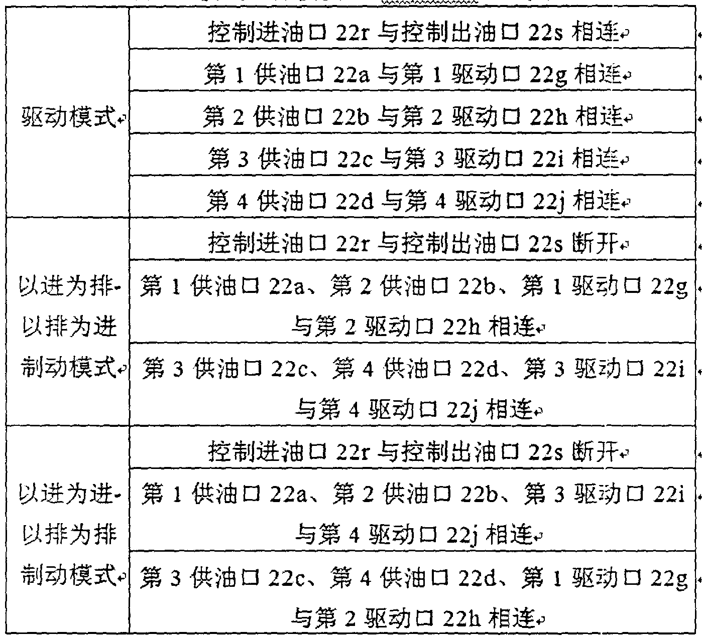
图 37-图 40分别是用于以进为进-以排为排制动模式的旋转式模式选择模块 主视图、 左视图、 后视图与俯视图。 图 41-图 44分别是用于以进为进-以排为排 制动模式的直动式模式选择模块主视图、左视图、 后视图与俯视图。 图 45-图 47 是用于以进为排-以排为进制动模式的旋转式模式选择模块主视图、 左视图与俯 视图。 图 48-图 52分别是用于以迸为排 -以排为进制动模式的直动式模式选择模 块主视图、 左视图、 第 1、 3、 5横截面图、 第 2、 4、 6横截面图和第 7横截面 图。 这几类模式选择模块 22均采用开有油口的模式选择模块外壳 22η与幵槽的 模式选择模块轴芯 22q, 模式选择模块轴芯 22q通过电磁、 液压、 机械或者气动 机构驱动, 具有两个位置。 当内燃机作为动力源的驱动模式时, 不驱动模式选 择模块轴芯 22q。 当内燃机作为消耗源的制动模式时, 驱动模式选择模块轴芯 22q旋转过一定角度或者沿轴向移动一定距离。
图 53 是用于以进为排-以排为进制动模式的幵关阀组件式模式选择模块示 意图。 图 54-图 56分别是旋转式开关阀组件主视图、 左视图与俯视图。 图 57- 图 59分别是直动式开关阀组件主视图、 左视图与俯视图。 图 60是独立开关阀 式幵关阀组件示意图。 这是由于对于以进为排-以排为进制动模式, 在驱动模式
与制动模式下, 模式选择模块第 1供油口 22a与模式选择模块第 1驱动口 22g 相连, 模式选择模块第 2供油口 22b与模式选择模块第 2驱动口 22h相连, 模 式选择模块第 3供油口 22c与模式选择模块第 3驱动口 22i相连,模式选择模块 第 4供油口 22d与模式选择模块第 4驱动口 22j相连。
开关阀组件 27可采用双层嵌套式结构,包括幵有油口的幵关阀组件外壳 27η 与开槽的幵关阀组件轴芯 27q, 开关阀组件轴芯 27q通过电磁、 液压、机械或者 气动机构驱动在开关阀组件外壳 27η 内进行旋转或者沿轴向移动, 具有两个位 置; 幵关阀组件 27设置有幵关阀组件第 1油口 27a、 开关阀组件第 2油口 27b、 开关阀组件第 4油口 27d、 幵关阀组件第 5油口 27e、 幵关阀组件第 6油口 27f 和开关阀组件第 8油口 27h, 模式选择模块第 1供油口 22a、 模式选择模块第 1 驱动口 22g与开关阀组件第 1油口 27a三者相连,模式选择模块第 2供油口 22b、 模式选择模块第 2驱动口 22h与开关阀组件第 5油口 27e三者相连, 模式选择 模块第 3供油口 22c、 模式选择模块第 3驱动口 22i与幵关阔组件第 2油口 27b 三者相连, 模式选择模块第 4供油口 22d、 模式选择模块第 4驱动口 2¾与开关 阀组件第 6油口 27f三者相连, 模式选择模块控制进油口 22r与开关阀组件第 4 油口 27d相连, 模式选择模块控制出油口 22s与开关阀组件第 8油口 27h相连; 在驱动模式下, 不驱动幵关阀组件轴芯 27q, 此时, 开关阀组件第 1油口 27a与 开关阀组件第 5油口 27e断开, 开关阀组件第 2油口 27b与幵关阀组件第 6油 口 27f断幵, 开关阀组件第 4油口 27d与开关阀组件第 8油口 27h相连,在制动 模式下, 幵关阀组件轴芯 27q旋转过一定角度或者沿轴向移动一定距离, 开关 阀组件第 1油口 27a与幵关阀组件第 5油口 27e相连, 幵关阀组件第 2油口 27b 与幵关阀组件第 6油口 27f相连, 幵关阀组件第 4油口 27d与开关阀组件第 8 油口 27h断开。
幵关阀组件 27还可采用独立幵关阀的结构, 包括第 1开关阀 23、第 2开关 阀 24和第 4开关阀 26; 幵关阀组件第 5油口 27e与第 1开关阀第 1油口 23a相 连, 开关阀组件第 1油口 27a与第 1开关阀第 2油口 23b相连, 开关阀组件第 6 油口 27f与第 2幵关阀第 1油口 24a相连,开关阀组件第 2油口 27b与第 2开关 阀第 2油口 24b相连, 幵关阀组件第 8油口 27h与第 4幵关阀第 1油口 26a相 连, 幵关阀组件第 4油口 27d与第 4幵关阀第 2油口 26b 连; 在驱动模式下,
第 4幵关阀第 1油口 26a与第 4开关阀第 2油口 26b相连, 第 1开关阀第 1油 口 23a与第 1开关阀第 2油口 23b断幵,第 2开关阀第 1油口 24a与第 2幵关阀 第 2油口 24b断幵; 在制动模式下, 驱动第 4幵关阀第 1油口 26a与第 4开关 阀第 2油口 26b断幵, 第 1幵关阀第 1油口 23a与第 1开关阀第 2油口 23b相 连, 第 2幵关阀第 1油口 24a与第 2开关阀第 2油口 24b相连。
应该注意到本例中阶段限定模块 2与模式选择模块 22的功能独立, 根据实 际应用中是否有制动模式来选择是否设置模式选择模块 22, 而对阶段限定模块 2及系统其它部件没有影响。 对于根据制动模式及模式选择模块 22的驱动方式 的不同, 选取模式选择模块 22的结构。 对于不同缸数的内燃机, 只需要增减阶 段限定模块 2与模式选择模块 22上的特定的油口截面即可, 无需对其他油口截 面以及系统其它部件进行改变。 对于气门可变灵活程度、 内燃机转速、 系统整 体布置等要求不同, 只需改变控制模块与输油模块的元件即可, 对系统其他部 分没有影响。 对于不同的内燃机点火顺序, 只需要调节阶段限定模块轴芯 2η各 油口截面的幵口角度, 或者对于有制动模式的内燃机, 改变阶段限定模块 2 与 模式选择模块 22之间油路的连接对象, 对于无制动模式的 ¾燃机, 改变阶段限 定模块 2 与各缸气门驱动模块之间油路的连接对象即可。 因此, 只需要简单调 整即可适应不同的机型, 系统具有广阔的应用范围。 与此^时, 阶段限定模块 2 与模式选择模块 22 的结构与油口位置等具体结构均根据实际安装要求进行调 整, 并且系统各部件间采用油管连接, 可以很好地满足系统在应用车型上的布 置要求。
以采用以进为排-以排为进制动模式的 1-2-4-3 式自然吸气式内燃机的供油 侧控制 +非独立泄油阀的全可变气门驱动系统为例加以说明。 以泄油阀 9为常闭 阀; 第 1两位三通阀 19不通电时, 第 1两位三通阀供油口 19a与第 1两位三通 阀输油口 19b相连, 第 1两位三通阀驱动口. 19c堵塞; 第 2两位三通阀 21不通 电时, 第 2两位三通阀供油口 21a与第 2两位三通阀输油口 21b相连, 第 2两 位三通阀驱动口 21c堵塞为例。 图 61是该情况下单气门的模块化多功能可变气 门驱动系统示意图。
由于该情况下系统的设计特点, 气门驱动模块 1 的运行情况由第 1供油模 块 6与阶段限定模块 2的运动规律、 以及模式选择模块 22、 第 1两位三通阀 19
与泄油阀 9的工作状态共同决定。 按照模式选择模块 22的工作状态, 可将气门 驱动模块 1的工作过程分成驱动模式与制动模式, 其工作过程为-
(一) 驱动模式
当内燃机处于作为动力源的驱动模式时, 不驱动模式选择模块 22, 保持模 式选择模块第 1驱动供油口 22a与模式选择模块第 1驱动口 22g连通, 模式选 择模块控制迸油口 22r与模式选择模块控制出油口 22s相连。 阶段限定模块第 1 驱动口 2e与阶段限定模块第 2供油口 2a始终不相连, 因此, 气门驱动模块 1 只能在由第 1供油模块 6与阶段限定模块 2的运动规律限制的范围内工作, 并 且在此范围内由第 1两位三通阀 19与泄油阀 9的工作状态调节具体的气门运行 参数, 其工作过程为-
( 1 ) 气门可被驱动阶段- 0° CA-3600 CA
在此阶段内, 阶段限定模块第 1驱动口 2e与阶段限定模块第 1供油口 2b 相连, 阶段限定模块第 i驱动口 2e与阶段限定模块第 2 :油口 2d断幵。 驱动 模式下的气门驱动油路, 即阶段限定模块第 1供油口 2b、 阶段限定模块第 1驱 动口 2e、 模式选择模块第 1驱动供油口 22a与模式选择模块第 1驱动口 22g完 全连通。
( a) 第 1供油模块 6供油阶段: 0° CA-1800 CA
此时,阶段限定模块第 1驱动口 2e与阶段限定模块第 1泄油口 2c相连。驱 动模式下的第 1泄油油路, 即模式选择模块第 1驱动口 22g、 模式选择模块第 1 驱动供油口 22a、阶段限定模块第 1驱动口 2e与阶段限定模块第 1泄油口 2c被 完全连通。 可实现:
a) 气门开启过程: 当第 1供油模块 6进入供油阶段时, 当气门驱动幵启正 时信号未达到时, 第 1两位三通阀 19与泄油阀 9均不被激励, 即第 1两位三通 阀供油口 19a与第 1两位三通阀输油口 1%相连, 第 1两位三通阀驱动口 19c 堵塞; 泄油阀进油口 9b与泄油阀出油口 9a断幵。 第 1供油模块 6内的液压油 通过第 1两位三通阀 19、 输油模块 7回到油箱 8。 当气门驱动开启正时信号到 达时, 第 1两位三通阀 19被激励, 即第 1两位三通阀供泊口 19a与第 1两位三 通阀驱动口 19c相连, 第 1两位三通阀输油口 1%堵塞。 第 1供油模块 6内的 液压油通过第 1两位三通阀 19后, 再通过驱动模式下的气门驱动油路, 进入气
门驱动模块 1中, 克服气门驱动模块 1弹簧的作用力, 驱动气门开启。
b) 气门开启保持: 当气门驱动停止正时信号达到时, 第 1 两位三通阀 19 不被激励, 即第 1两位三通阀供油口 19a与第 1两位三通阀输油口 1%相连, 第 1两位三通阀驱动口 19c堵塞。 气门驱动模块 1 内的液压油被阻塞, 气门保 持在最大升程位置。 此时第 1供油模块 6仍处于供油阶段时, 第 1供油模块 6 内的液压油通过第 1两位三通阀 19、 输油模块 7被推回到泊箱 8中。
c)气门泄油关闭: 当气门驱动泄油关闭正时信号达到 ΗΓ, 泄油阀 9被激励, 泄油阀进油口%与泄油阀出油口 9a相连。 在气门驱动模块 1弹簧的作用下, 气门驱动模块 1 内的液压油通过驱动模式下的第 1泄油油路, 泄油阀 9回到油 箱 8中, 实现了气门的泄油关闭过程。 此时第 1供油模块 6仍处于供油阶段时, 第 1供油模块 6内的液压油通过第 1两位三通阀 19、 输油模块 7被推回到油箱 8中。
(b) 第 1供油模块 6吸油阶段: 180。 CA-3600 CA
此时,阶段限定模块第 1驱动口 2e与阶段限定模块第 I泄油口 2c断开。可 实现:
a) 气门开启保持: 当第 1两位三通阀 19不被激励时, 气门驱动模块 1 内 的液压油被阻塞, 气门保持在最大升程位置。 此时第 1供油模块 6仍处于吸油 阶段时, 油箱 8内的液压油通过输油模块 7、 第 1两位三通阀 19进入第 1供油 模块 6中。
b) 气门吸油关闭: 当气门吸油关闭正时信号达到时, 第 1 两位三通阀 19 被激励, 即第 1两位三通阀供油口 19a与第 1两位三通阀驱动口 19c相连, 第 1 两位三通阀输油口 19b堵塞。 在气门驱动模块 1弹簧与第 1供油模块 6吸油的 作用下, 气门驱动模块 1 内的液压油通过驱动模式下的驱动油路、 第 1两位三 通阀 19回到第 1供油模块 6中, 实现了气门的吸油关闭过程。
( 2 ) 气门关闭保持阶段: 360° CA-720° CA
此阶段内, 阶段限定模块 2将阶段限定模块第 1供油口 2b与阶段限定模块 第 1驱动口 2e断开,将阶段限定模块第 1泄油口 2c与阶段限定模块第 1驱动口 2e断幵, 将阶段限定模块第 2泄油口 2d与阶段限定模块第 1驱动口 2e连通。 驱动模式下的第 2泄油油路, 即模式选择模块第 1驱动口 22g、模式选择模块第
1驱动供油口 22a、 阶段限定模块第 1驱动口 2e、 阶段限定模块第 2泄油口 2d、 模式选择模块控制进油口 22r与模式选择模块控制出油口 22s被完全连通。气门 驱动模块〖通过驱动模式下的第 2泄油油路与油箱 8相连, 可实现气门的关闭 以及关闭保持, 可取代气门间隙调节模块。
(二) 制动模式
当内燃机处于作为消耗源的制动模式时, 驱动模式选择模块 22运动, 将模 式选择模块第 1供油口 22a、 模式选择模块第 2供油口 22b -、 模式选择模块第 1 驱动口 22g与模式选择模块第 2驱动口 22h四者相连, 模式选择模块控制进油 口 22r与模式选择模块控制出油口 22s断开。此时, 气门驱动模块 1的工作范围 受到第 1供油模块 6或者第 2供油模块 5与阶段限定模块 2的运动规律限制, 并且在此范围内由第 1两位三通阀 19或者第 2两位三通阀 21与泄油阀 9工作 状态调节具体的气门运行参数, 其工作过程为:
此阶段是第 1供油模块 6从供油起始点开始的一个供油 +吸油的运行周期。 同时, 阶段限定模块 2将阶段限定模块第 1供油口 2b与阶段限定模块第 1驱动 口 2e相连, 阶段限定模块第 1供油口 2a与阶段限定模块第 1驱动口 2e断幵, 阶段限定模块第 2泄油口 2d与阶段限定模块第 1驱动口 2e断开, 阶段限定模 块第 1供油口 2b与阶段限定模块第 2驱动口 2f断开,阶段裉定模块第 2供油口 2a与阶段限定模块第 2驱动口 2f断开, 阶段限定模块第 2泄油口 2d与阶段限 定模块第 2驱动口 2f相连,阶段限定模块第 1泄油口 2c与 3介段限定模块第 2驱 动口 2f断幵。制动模式下的第 1气门制动油路,即阶段限定模块第 1供油口 2b、 阶段限定模块第 1驱动口 2e、 模式选择模块第 1供油口 22a、 模式选择模块第 1 驱动口 17%以及模式选择模块第 2驱动口 22h被完全连通。
( 1 ) 第 1供油模块 6供油阶段: 0° CA-180。CA
阶段限定模块 2将阶段限定模块第 1泄油口 2c与阶段限定模块第 1驱动口 2e连通。 制动模式下的第 1泄油油路, 即模式选择模块第 1驱动口 22g以及模 式选择模块第 2驱动口 22h、 模式选择模块第 1供油口 22a、 阶段限定模块第 1 驱动口 2e与阶段限定模块第 1泄油口 2c被完全连通。除了驱动油路不同外,在 此阶段内可实现的气门运行过程与驱动模式下气门可被驱动阶段的第 1 供油模 块 6供油阶段内气门运行过程一样, 此处不再重复。
( 2 ) 第 1供油模块 6吸油阶段- 180。 CA-3600 CA
阶段限定模块 2将阶段限定模块第 1泄油口 2c与阶段限定模块第 1驱动口 2e 断开。 除了驱动油路不同外, 在此阶段内可实现的气门运行过程与驱动模式 下气门可被驱动阶段的第 1供油模块 6吸油阶段内气门运行过程一样, 此处不 再重复。
由于在一个阶段限定模块运行周期内, 驱动模式具有 1 个气门可被驱动阶 段, 而制动模式具有 2个气门可被驱动阶段, 因此, 可实现 360°CA/循环的压气 机的制动模式所要求的可变气门事件等。
不同缸数、 气门可变灵活程度、 有 /无制动模式、 不同^动模式、 不同控制 位置下的气门驱动系统的运行情况, 该过程随着具体情况下系统各部件的运行 特点的不同略有差别, 以表格的形式对此进行介绍, 不单独进行详细说明。 表 6-表 8分别是驱动模式、 以进为排 -以排为进制动模式和以进为进-以排为排制动 模式下 4缸内燃机气门驱动系统运行情况。其中,从 1-6的编号的系统类型分别 为供油侧控制的连续可变式、 气门侧控制的连续可变式、 气门侧控制 +非独立泄 油阀的全可变式、 供油侧控制 +独立泄油阀的全可变式和气门侧控制 +独立泄油 阀的全可变式气门驱动系统。 +代表控制阀布置在模式选择^块供油口侧, -代表 控制阀布置在模式选择模块驱动口侧。

以进为排-以排为进制动模式下 ^
各缸气门驱动模块 供油和控制部件
1缸 +4缸 ^ 2缸 +3缸 供 第 1供油模块 6: 第 2供油模块 5 : - 油 * 0。-180°及 360。-480 180。-360。及 480°-600 ,
1^ 第 1两位两通阀 14-, 第 2两位两通阀 15 第 1 -1两位两通阀 141或者第 第 2-1两位两通阀 15 1或者第
1-2两位两通阀 142^ 2-2两位两通阀 152 第 1两位三通阀 19和泄油阀 9*第 2两位三通阀 21禾 [泄油阀 第 1 -1两位三通阀 191和泄油阀 第 2-1两位三通阀 211和泄油阀
4^ 或者第 1 -2两位三通阀 192和 9或者第 2-2两位三通阀 212和 泄油阀 9 泄油阀^ 第 1两位三通阀 19和第 1泄油 第 2两位 直阀 21和第 4泄油
5^ 阀 91或者第 1两位三通阀 19 阀 94或者第 2两位三通阀 21
和第 2泄油阀 92 和第 5泄油阀 95^ 第 1 -1两位三通阀 191和第 1 第 2-1两位三通阀 211和第 4
6*' 泄油阀 91或者第 1-2两位三通 泄油阀 94或者第 2-2两位三通 阀 192和第 2泄油阀 92·^ 阀 212和第 5泄油阀 95
表 8 以进为进-以排为棑制动模式下

Claims
1. 一种用于 4缸内燃机的模块化多功能可变气门驱动系统, 它主要包括气 门驱动模块 (1 )、 第 1供油模块 (6)、 第 2供油模块 (5 )、 输油模块 (7)、 油 箱 (8)、 泄油阀 (9) 以及油管; 其特征是: 它还包括阶段限定模块 (2)、 模式 选择模块(22)、第 1控制模块(3 )、第 2控制模块(4) ; 所述第 1供油模块(6) 与第 2供油模块(5 )为相位相差 180度凸轮轴转角的凸轮 -柱塞式供油模块, 其 旋转周期为内燃机点火间隔角的 2倍, 即 360度曲轴转角; 第: 1控制模块 (3 ) 设置有第 1控制模块第 1供油口 (3a)、 第 1控制模块泄油口 (3b)、 第 1控制 模块第 1驱动口 (3c) 和第 1控制模块输油口 (3d); 第 2控制模块 (4) 设置 有第 2控制模块第 1供油口 (4a)、 第 2控制模块泄油口 (4b)、 第 2控制模块 第 1驱动口 (4c ) 和第 2控制模块输油口 (4d) ; 输油模块 (7 ) 设置有输油模 块第 2输油口 (7a)、 输油模块泄油口 (7b)、 输油模块第 1输油口 (7c)和输油 模块进油口 (7d) ; 阶段限定模块 (2 ) 设置有阶段限定模块第 2供油口 (2a)、 阶段限定模块第 1供油口 (2b)、 阶段限定模块第 2泄油口 (2d)、 阶段限定模 块第 1驱动口 (2e)、 阶段限定模块第 2驱动口 (2f)、 阶段限定模块第 3驱动口
( 2g) 和阶段限定模块第 4驱动口 (2h) ; 输油模块泄油口 (7b)、 输油模块进 油口 (7d)、 第 1控制模块泄油口 (3b)、 第 2控制模块泄油口 (4b) 均与油箱
( 8 ) 相连, 输油模块第 2输油口 (7a) 与第 2控制模块输油口 (4d) 相连, 输 油模块第 1输油口 (7c) 与第 1控制模块输油口 (3d)相连, 第 1控制模块第 1 供油口 (3a) 与第 1供油模块 (6) 相连, 第 2控制模块第 1供油口 (4a) 与第 2供油模块 (5 ) 相连, 第 1控制模块第 1驱动口 (3c) 与阶段限定模块第 1供 油口 (2b) 相连, 第 2控制模块第 1驱动口 (4c) 与阶段限^模块第 2供油口
( 2a) 相连; 对于非独立泄油阀的全可变式气门驱动系统, 增设泄油阀 (9 ), 阶段限定模块(2 )还设置有阶段限定模块第 1泄油口 (2c), 价段限定模块第 1 泄油口 (2c ) 与泄油阀进油口 (%) 相连, 泄油阀出油口 (9a) 与油箱 (8 ) 相 连; 无制动模式时, 阶段限定模块第 1驱动口 (2e)、 阶段限定模块第 2驱动口
( 2f)、 阶段限定模块第 3驱动口 (2g) 和阶段限定模块第 4驱动口 (2h) 分别 与 1缸、 4缸、 2缸和 3缸的气门驱动模块, 阶段限定模块第 2泄油口 (2d) 与 油箱 (8 ) 相连, 有制动模式时, 增设模式选择模块 (22), 模式选择模块 (22 )
设置有模式选择模块第 1供油口 (22a)、 模式选择模块第 2供油口 (22b)、 模 式选择模块第 3供油口 (22c) 和模式选择模块第 4供油口 (22d), 这四者分别 与阶段限定模块第 1驱动口 (2e)、 阶段限定模块第 2驱动口 (2f)、 阶段限定模 块第 3驱动口(2g)和阶段限定模块第 4驱动口(2h)相连, 模式选择模块(22 ) 还设置有模式选择模块第 1驱动口 (22g)、 模式选择模块第 2驱动口 (22h)、 模式选择模块第 3驱动口 (22i ) 和模式选择模块第 4驱动口 (22j ), 这四者分 别与 1缸、 4缸、 2缸和 3缸的气门驱动模块相连, 模式选择模块 (22 ) 还设置 有模式选择模块控制进油口 (22r) 和模式选择模块控制出油口 (22s), 二者分 别与阶段限定模块第 2泄油口 (2d) 和油箱 (8 ) 相连; 对于缸数为 4的整数倍 的内燃机的气门驱动系统, 按照点火顺序相隔 180度曲轴转角分组, 每 4缸一 组, 每组采用一套上述可变气门驱动系统。
2. 根据权利要求 1所述的一种用于 4缸内燃机的模块化多功能可变气门驱 动系统, 其特征是: 对于气门侧控制连续可变式或者独立泄油阀的全可变式气 门驱动系统, 第 1控制模块 (3 ) 增设第 1控制模块第 5驱动口 (3k) 和第 1控 制模块第 6驱动口 (3m), 第 1控制模块第 5驱动口 Gk)连接到阶段限定模块 第 1驱动口 (2e) 与模式选择模块第 1供油口 (22a) 之间的油路或者模式选择 模块第〗驱动口 (22g) 与 1缸的气门驱动模块之间的油路上, 第 1控制模块第 6驱动口 (3m)连接到阶段限定模块第 2驱动口 (2f)与模式选择模块第 2供油 口 (22b) 或者模式选择模块第 2驱动口 (22h) 与 4缸的气门驱动模块之间的 油路上, 第 2控制模块 (4 ) 增设第 2控制模块第 5驱动口 (4k) 和第 2控制模 块第 6驱动口 (4m), 第 2控制模块第 5驱动口 (4k) 连接到阶段限定模块第 3 驱动口 (2g) 与模式选择模块第 3供油口 (22c) 之间的油路或者模式选择模块 第 3驱动口 (22i ) 与 2缸的气门驱动模块之间的油路上, 第 2控制模块第 6驱 动口 (4m ) 连接到阶段限定模块第 4驱动口 (2h) 与模式选择模块第 4供油口
( 22d)或者模式选择模块第 4驱动口 (22j )与 3缸的气门驱动模块之间的油路 上。
3. 根据权利要求 1所述的一种用于 4缸内燃机的模块化多功能可变气门驱 动系统, 其特征是: 对于气门侧控制的全可变式气门驱动系统, 第 1 控制模块
( 3 ) 增设第 1控制模块第 2供油口 (3e)、 第 1控制模块第 3供油口 (3f)、 第
1控制模块第 2驱动口 (3h) 和第 1控制模块第 3驱动口 (3 D, 第 1控制模块 第 2供油口 (3e) 和第 1控制模块第 2驱动口 (3h) 分别与 3介段限定模块第 1 驱动口 (2e)和模式选择模块第 1供油口 (22a)或者模块第〗驱动口 (22g)和 1缸的气门驱动模块相连, 第 1控制模块第 3供油口 (3f) 和第 1控制模块第 3 驱动口 (3i ) 分别与阶段限定模块第 2驱动口 (2f)和模式选择模块第 2供油口 ( 22b )或者模式选择模块第 2驱动口 (22h)和 4缸的气门驱动模块相连, 第 2 控制模块 (4) 还需要增设第 2控制模块第 2供油口 (4e)、 第 2控制模块第 3 供油口 (4f)、第 2控制模块第 2驱动口 (4h)和第 2控制模块第 3驱动口 (4i), 第 2控制模块第 2供油口 (4e ) 和第 2控制模块第 2驱动口 (4h) 分别与阶段 限定模块第 3驱动口 (2g) 和模式选择模块第 3供油口 (22c ) 或者模式选择模 块第 3驱动口(22i )和 2缸的气门驱动模块相连,第 2控制模:央第 3供油口 (4f) 和第 2控制模块第 3驱动口 (4i )分别与阶段限定模块第 4驱动口 (2h)和模式 选择模块第 4供油口 (22d)或者模式选择模块第 4驱动口 (22j )和 3缸的气门 驱动模块相连。
4. 根据权利要求 1所述的一种用于 4缸内燃机的模块化多功能可变气门驱 动系统, 其特征是: 对于气门侧控制 +独立泄油阀的全可变式气门驱动系统, 取 消阶段限定模块 (2 ) 和模式选择模块 (22), 第 1控制模块箅 1供油口 (3a)、 第 1控制模块第 1驱动口 (3c)、 第 1控制模块第 2供油口 (3e) 和第 1控制模 块第 3供油口(3f)均与第 1供油模块(6)相连,第 1控制模块第 2驱动口(3h) 和第 1控制模块第 5驱动口 Gk) 均与 1缸的气门驱动模块相连, 第 1控制模 块第 3驱动口 (3i) 和第 1控制模块第 6驱动口 (3m) 均与 4缸的气门驱动模 块相连, 第 2控制模块第 1供油口 (4a)、 第 2控制模块第 1驱动口 (4c)、 第 2 控制模块第 2供油口 (4e)和第 2控制模块第 3供油口 (4f)均与第 2供油模块
( 5 ) 相连, 第 2控制模块第 2驱动口 (4h) 和第 2控制模块第 5驱动口 (4k) 均与 2缸的气门驱动模块相连, 第 2控制模块第 3驱动口 (4i )和第 2控制模块 第 6驱动口 (4m) 均与 3缸的气门驱动模块相连。
5. 根据权利要求 1所述的一种用于 4缸内燃机的模块化多功能可变气门驱 动系统, 其特征是: 对于连续可变式气门驱动系统, 输油模块 (7 ) 包括输油泵
( 10)、 输油泵安全阀 (11 )、 第 1输油单向阀 (12 ) 和第 2输油单向阔 (13 ),
输油泵进油口 (10a)与输油模块进油口 (7d)相连, 输油泵安全阀出油口 (11a) 与输油模块泄油口 (7b) 相连, 第 1输油单向阀出油口 (12b) 与输油模块第 1 输油口 (7c)相连, 第 2输油单向阀出油口 (13b)与输油模块第 2输油口 (7a) 相连, 输油泵出油口 (10b)、 输油泵安全阀进油口 (l lb)、 第 1 输油单向阀进 油口 (12a)与第 2输油单向阀进油口 (13a) 四者相连; 对于全可变式气门驱动 系统, 输油模块(7 )包括输油泵(10)、 输油泵安全阀 (11 )、 输油单向阀 (16 ) 和系统安全阀 (17), 输油泵进油口 (10a) 与输油模块进油口 (7d) 相连, 输 油泵出油口 (10b)、 输油泵安全阀进油口 (l ib)与输油单向阀进油口 (16a)三 者相连, 输油泵安全阀出油口 (l la)、 系统安全阀出油口 (17a) 与输油模块泄 油口 (7b ) 三者相连, 输油单向阀出油口 (16b)、 系统安全阀迸油口 (17b)、 输油模块第 2输油口 (7a) 与输油模块第 1输油口 (7c) 四者相连。
6. 根据权利要求 1所述的一种用于 4缸内燃机的模块化多功能可变气门驱 动系统, 其特征是: 对于供油侧控制的连续可变式气门驱动系统, 第 1 控制模 块 (3 ) 包括第 1两位两通阀 (14 ); 第 1两位两通阀出油口 (14a) 与第 1控制 模块泄油口 (3b) 相连; 第 1两位两通阀进油口 (14b)、 第 1控制模块第 1供 油口 (3a)、 第 1控制模块第 1驱动口 (3c) 与第 1控制模块输油口 (3d) 四者 相连; 对于气门侧控制的连续可变式气门驱动系统, 第 1控制模块 (3 ) 包括第 1- 1两位两通阀(141 )和第 1-2两位两通阀(142 ),第 1控制模块第 1供油口(3a)、 第 1控制模块第 1驱动口 (3c ) 与第 1控制模块输油口 (3d ) 三者相连, 第 1-1 两位两通阀出油口 (141a)、 第 1-2两位两通阀出油口 (142a) 与第 1控制模块 泄油口 (3b) 三者相连, 第 1-1两位两通阀进油口 (141b ) 与第 1控制模块第 5 驱动口 (3k)相连, 第 1-2两位两通阀进油口 (142b)与第〗控制模块第 6驱动 口 Gm ) 相连; 对于供油侧控制 +非独立泄油阀的全可变式气门驱动系统, 第 1 控制模块 (3 ) 包括第 1单向阀 (18 ) 和第 1两位三通阀 (19), 第 1单向阀进 油口 (18a) 与第 1控制模块泄油口 (3b) 相连, 第 1两位三通阀供油口 (19a) 与第 1控制模块第 1供油口 (3a) 相连, 第 1两位三通阀输油口 (1%) 与第 1 控制模块输油口 (3d) 相连, 第 1两位三通阀驱动口 (19c〕 与第 1控制模块第 1驱动口 (3c)相连, 第 1单向阀出油口 U 8b)与第 1两位三通阀供油口 (19a) 或者第 1 两位三通阀驱动口 (19c) 相连; 对于气门侧控制 +非独立泄油阀的全 可变式气门驱动系统, 第 1控制模块(3 )包括第 1单向阀 (18)、 第 1-1两位三
通阔 ( 191 )和第 1-2两位三通阀 (192), 第 1单向阀进油口 〈18a)与第 1控制 模块泄油口 (3b) 相连, 第 1单向阀出油口 (18b)、 第 1控制模块第 1供油口 ( 3a) 与第 1控制模块第 1驱动口 (3c) 三者相连, 第 1-1两位三通阀输油口 ( 191b) , 第 1-2两位三通阔输油口 (192b) 与第 1控制模块输油口 (3d) 三者 相连, 第 1-1两位三通阀供油口 ( 191a)与第 1控制模块第 2供油口 (3e)相连, 第 1 -2两位三通阀供油口 (192a)与第 1控制模块第 3供油口 (3f)相连, 第 1-1 两位三通阀驱动口 (191c) 与第 1控制模块第 2驱动口 (3h)相连, 第 1-2两位 三通阀驱动口 (192c ) 与第 1控制模块第 3驱动口 (3i)相连; 对于供油侧控制 +独立泄油阀的全可变式气门驱动系统,第 1控制模块(3 )包括第 1单向阀(18)、 第 1两位三通阀 (19)、 第 1泄油阔 (91 ) 和第 2泄油阀 (92), 第 1两位三通 阀供油口 (19a) 与第 1控制模块第 1供油口 (3a) 相连, 第 1两位三通阀输油 口 (1%) 与第 1控制模块输油口 (3d) 相连, 第 1两位三通阀驱动口 (19c) 与第 1控制模块第 1驱动口 (3c)相连, 第 1泄油阀出油口 (91a)、 第 2泄油阔 出油口 (92a)、 第 1单向阀进油口 (18a) 与第 1控制模块泄油口 (3b) 四者相 连, 第 1泄油阀进油口 (91b) 与第 1控制模块第 5驱动口 (3k) 相连, 第 2泄 油阀进油口 (92b)与第 1控制模块第 6驱动口 (3m)相连, 第 1单向阀出油口 ( 18b) 与第 1两位三通阀供油口 (19a) 或者第 1两位三通阀驱动口 (19c) 相 连; 对于气门侧控制 +独立泄油阀的全可变式气门驱动系统, 第 1控制模块(3 ) 包括第 1单向阀 (18 )、 第 1-1两位三通阀 (191 )、 第 1-2两位三通阀 (192)、 第 1泄油阀 (91 ) 和第 2泄油阀 (92), 第 1单向阀出油口 (18b)、 第 1控制模 块第 1供油口 (3a) 与第 1控制模块第 1驱动口 (3c)三者相连, 第 1-1两位三 通阀输油口 (191b)、 第 1-2两位三通阀输油口 (192b) 与第 1控制模块输油口 (3d)三者相连, 第 1-1两位三通阀供油口 (191a)与第 1控制模块第 2供油口 ( 3e )相连, 第 1-2两位三通阀供油口 (192a)与第 1控制模块第 3供油口 (3f) 相连, 第 1-1两位三通阀驱动口 (191c)与第 1控制模块第 2驱动口(3h)相连, 第 1-2两位三通阀驱动口 (192c) 与第 1控制模块第 3驱动口 (3i ) 相连, 第 1 泄油阀出油口 (91a)、 第 2泄油阀出油口 (92a)、 第 1单向阀进油口 (18a) 与 第 1控制模块泄油口 (3b) 四者相连, 第 1泄油阀进油口 (91b ) 与第 1控制模 块第 5驱动口 (3k) 相连, 第 2泄油阀进油口 (92b) 与第 1控制模块第 6驱动 口 (3m) 相连。
7. 根据权利要求 1所述的一种用于 4缸内燃机的模块化多功能可变气门驱 动系统, 其特征是: 对于供油侧控制的连续可变式气门驱动系统, 第 2控制模 块 (4 ) 包括第 2两位两通阀 (15 ), 第 2两位两通阀出油口 (15a) 与第 2控制 模块泄油口 (4b) 相连, 第 2两位两通阀进油口 (15b)、 第 2控制模块第 1供 油口 (4a)、 第 2控制模块第 1驱动口 (4c) 与第 2控制模块输油口 (4d) 四者 相连; 对于气门侧控制的连续可变式气门驱动系统, 第 2控^模块 (4 ) 包括第 2-1两位两通阀(151 )和第 2-2两位两通阀(152),第 2控制模块第 1供油口(4a)、 第 2控制模块第 1驱动口 (4c) 与第 2控制模块输油口 (4d) 三者相连, 第 2-】 两位两通阀出油口 (151a)、 第 2-2两位两通阀出油口 (152a) 与第 2控制模块 泄油口 (4b) 三者相连, 第 2-1两位两通阀进油口 (151b) 与第 2控制模块第 5 驱动口 (4k)相连, 第 2-2两位两通阔进油口 (152b)与第 2控制模块第 6驱动 口 (4m ) 相连; 对于供油侧控制 +非独立泄油阀的全可变式气门驱动系统, 第 2 控制模块 (4 ) 包括第 2单向阀 (20) 和第 2两位三通阀 (21 ), 第 2单向阀进 油口 (20a) 与第 2控制模块泄油口 (4b) 相连, 第: 2两位三通阀供油口 (21a) 与第 2控制模块第 1供油口 (4a) 相连, 第 2两位三通阀输油口 (21b) 与第 2 控制模块输油口 (4d) 相连, 第 2两位三通阀驱动口 (21c) 与第 2控制模块第 1驱动口 (4c)相连, 第 2单向阀出油口 (20b )与第 2两位三通阀供油口 (21a) 或者第 2两位三通阀驱动口 (21c ) 相连; 对于气门侧控制 +非独立泄油阀的全 可变式气门驱动系统, 第 2控制模块(4)包括第 2单向阀 (20)、 第 2-1两位三 通阀 (211 )和第 2-2两位三通阀 (212), 第 2单向阀进油口 (20a) 与第 2控制 模块泄油口 (4b) 相连, 第 2单向阀出油口 (20b)、 第 2控制模块第 1供油口 (4a) 与第 2控制模块第 1驱动口 (4c) 三者相连, 第 2-1两位三通阀输油口 ( 211 b ) , 第 2-2两位三通阀输油口 (212b ) 与第 2控制模块输油口 (4d) 三者 相连, 第 2-1两位三通阀供油口 (211a)与第 2控制模块第 2供油口 (4e)相连, 第 2-2两位三通阀供油口 (212a)与第 2控制模块第 3供油口 (4f)相连, 第 2-1 两位三通阀驱动口 (211c)与第 2控制模块第 2驱动口 (4h)相连, 第 2-2两位 三通阀驱动口 (212c) 与第 2控制模块第 3驱动口 (4i ) 相连; 对于供油侧控制 +独立泄油阀的全可变式气门驱动系统,第 2控制模块(4 )包括第 2单向阀(20 )、 第 2两位三通阀 (21 )、 第 4泄油阀 (94 ) 和第 5泄油阀 (95 ), 第 2两位三通 阀供油口 (21a) 与第 2控制模块第 1供油口 (4a) 相连, 第 2两位三通阔输油
口 (21b ) 与第 2控制模块输油口 (4d) 相连, 第 2两位三通阀驱动口 (21c) 与第 2控制模块第 1驱动口 (4c)相连, 第 4泄油阀出油口 (94a)、 第 5泄油阀 出油口 (95a)、 第 2单向阀进油口 (20a) 与第 2控制模块泄油口 (4b) 四者相 连, 第 4泄油阀进油口 (94b) 与第 2控制模块第 5驱动口 (4k) 相连, 第 5泄 油阀进油口 (95b)与第 2控制模块第 6驱动口 (4m)相连, 第 2单向阀出油口 (20b) 与第 2两位三通阀供油口 (21a) 或者第 2两位三通阀驱动口 (21c) 相 连; 对于气门侧控制 +独立泄油阀的全可变式气门驱动系统, 第 2控制模块(4) 包括第 2单向阀 (20)、 第 2-1两位三通阔 (211 )、 第 2-2两位三通阀 (212 )、 第 4泄油阀 (94 ) 和第 5泄油阀 (95 ), 第 2单向阀出油口 (20b)、 第 2控制模 块第 1供油口 (4a) 与第 2控制模块第 1驱动口 (4c)三者相连, 第 2-1两位三 通阀输油口 (211b)、 第 2-2两位三通阀输油口 (212b) 与第 2控制模块输油口 (4d)三者相连, 第 2-1两位三通阀供油口 (211a)与第 2控制模块第 2供油口 (4e)相连, 第 2-2两位三通阀供油口 (212a)与第 2控制模块第 3供油口 (4f) 相连, 第 2-1两位三通阀驱动口 (211c)与第 2控制模块第 2驱动口(4h)相连, 第 2-2两位三通阀驱动口 (212c) 与第 2控制模块第 3驱动口 (4i) 相连, 第 4 泄油阀出油口 (94a)、 第 5泄油阀出油口 (95a)、 第 2单向阀进油口 (20a) 与 第 2控制模块泄油口 (4b) 四者相连, 第 4泄油阀进油口 (94b) 与第 2控制模 块第 5驱动口 (4k) 相连, 第 5泄油阀进油口 (95b) 与第 2控制模块第 6驱动 口 (4m ) 相连。
8. 根据权利要求 1所述的一种用于 4缸内燃机的模块化多功能可变气门驱 动系统, 其特征是: 所述阶段限定模块 (2 ) 采用三层嵌套式结构, 从外到内依 次为开有油口的阶段限定模块外壳 (2k)、 轴向开槽与开孔的阶段限定模块轴套 (2m)以及径向开槽的阶段限定模块轴芯(2n), 其中, 阶段限定模块轴芯(2η) 通过齿轮或者链轮传动机构由内燃机曲轴驱动, 每 720度曲轴转角旋转 1周, 阶段限定模块轴套 (2m) 固定嵌套在阶段限定模块外壳 (2k) 内部, 将依照内 燃机发火顺序, 随着阶段限定模块轴芯 (2η) 的不断旋转, 对于连续可变式气 门驱动系统, 阶段限定模块第 1驱动口 (2e) 和阶段限定模块第 2驱动口 (20 均间隔性地分别与阶段限定模块第 1供油口 (2b) 或者阶段限定模块第 2泄油 口(2d)相连, 阶段限定模块第 3驱动口(2g)和阶段限定模块第 4驱动口(2h) 均间隔性地分别与阶段限定模块第 2供油口 (2a) 或者阶段限定模块第 2泄油
口 (2d) 相连; 对于全可变式气门驱动系统, 阶段限定模块第 1 驱动口 (2e) 和阶段限定模块第 2驱动口 (2f) 均间隔性地分别与阶段限定模块第 1 供油口 (2b) , 阶段限定模块第 1泄油口 (2c) 或者阶段限定模块第 2泄油口 (2d) 相 连, 阶段限定模块第 3驱动口 (2g) 和阶段限定模块第 4驱动口 (2h) 均间隔 性地分别与阶段限定模块第 2供油口 (2a)、 阶段限定模块第 1泄油口 (2c) 或 者阶段限定模块第 2泄油口 (2d) 相连。
9. 根据权利要求 1所述的一种用于 4缸内燃机的模块化多功能可变气门驱 动系统, 其特征是: 所述模式选择模块 (22 ) 采用双层嵌套式结构, 包括开有 油口的模式选择模块外壳 (22η) 与开槽的模式选择模块轴芯 (22q), 模式选择 模块轴芯 (22q) 通过电磁、 液压、 机械或者气动机构驱动在模式选择模块外壳
( 22η) 内进行旋转或者沿轴向移动, 具有两个位置; 当内燃机作为动力源的驱 动模式时, 不驱动模式选择模块轴芯 (22q), 此时, 模式选择模块控制进油口
( 22r)与模式选择模块控制出油口(22s)相连,模式选择模块第 1供油口(22a) 与模式选择模块第 1驱动口 (22g) 相连, 模式选择模块第 2供油口 (22b) 与 模式选择模块第 2驱动口 (22h) 相连, 模式选择模块第 3供油口 (22c) 与模 式选择模块第 3驱动口 (22i)相连, 模式选择模块第 4供油口 (22d)与模式选 择模块第 4驱动口 (22j ) 相连; 当内燃机作为消耗源的制动模式时, 驱动模式 选择模块轴芯 (22q) 旋转过一定角度或者沿轴向移动一定距离, 模式选择模块 控制进油口 (22r) 与模式选择模块控制出油口 (22s) 断开, 采用以进为排-以 排为进制动模式时, 模式选择模块第 1供油口 (22a)、 模式选择模块第 2供油 口 (22b)、 模式选择模块第 1驱动口 (22g) 与模式选择模块第 2驱动口 (22h) 四者相连, 模式选择模块第 3供油口 (22c)、 模式选择模块第 4供油口 (22d)、 模式选择模块第 3驱动口 (22i) 与模式选择模块第 4驱动口 (22j ) 四者相连, 采用以进为进-以排为排制动模式时, 模式选择模块第 1供油口 (22a)、 模式选 择模块第 2供油口 (22b)、 模式选择模块第 3驱动口 (22i ) 与模式选择模块第 4驱动口 (22j ) 四者相连, 模式选择模块第 3供油口 (22c)、 模式选择模块第 4 供油口(22d)、模式选择模块第 1驱动口(22g)与模式选择模块第 2驱动口(22h) 四者相连。
10. 根据权利要求 1所述的一种用于 4缸内燃机的模块化多功能可变气门驱
动系统, 其特征是: 对于采用以进为排-以排为进制动模式的气门驱动系统, 模 式转换模块 (22 ) 采用开关阀组件式结构, 开关阀组件 (27 ) 采用双层嵌套式 结构, 包括开有油口的开关阀组件外壳(27η)与开槽的开关阀组件轴芯(27q), 开关阀组件轴芯 (27q) 通过电磁、 液压、 机械或者气动机构驱动在开关阀组件 外壳 (27η) 内进行旋转或者沿轴向移动, 具有两个位置; 开关阔组件 (27 ) 设 置有开关阀组件第 1油口 (27a)、 幵关阀组件第 2油口 (27b〉、 开关阀组件第 4 油口 (27d)、 开关阀组件第 5油口 (27e)、 开关阀组件第 6油口 (27f) 和开关 阀组件第 8油口 (27h), 模式选择模块第 1供油口 (22a)、 模式选择模块第 1 驱动口 (22g) 与开关阀组件第 1油口 (27a) 三者相连, 模式选择模块第 2供 油口 (22b)、 模式选择模块第 2驱动口 (22h) 与幵关阔组 ^第 5油口 (27e) 三者相连, 模式选择模块第 3供油口 (22c)、 模式选择模块第 3驱动口 (22i) 与开关阀组件第 2油口 (27b) 三者相连, 模式选择模块第 4供油口 (22d)、 模 式选择模块第 4驱动口 (22j ) 与开关阀组件第 6油口 (27f)三者相连, 模式选 择模块控制进油口 (22r)与开关阀组件第 4油口 (27d)相连, 模式选择模块控 制出油口 (22s)与开关阀组件第 8油口 (27h)相连; 在驱动模式下, 不驱动开 关阀组件轴芯 (27q), 此时, 开关阀组件第 1油口 (27a) 与开关阀组件第 5油 口 (27e) 断幵, 幵关阀组件第 2油口 (27b) 与幵关阀组件第 6油口 (27f) 断 开, 幵关阀组件第 4油口 (27d) 与幵关阀组件第 8油口 (27h) 相连, 在制动 模式下, 开关阀组件轴芯 (27q) 旋转过一定角度或者沿轴向移动一定距离, 开 关阀组件第 1油口 (27a) 与开关阀组件第 5油口 (27e)相连, 开关阀组件第 2 油口 (27b) 与开关阀组件第 6油口 (270 相连, 开关阀组件第 4油口 (27d) 与开关阀组件第 8油口 (27h)断开; 幵关阀组件(27 )采用独立开关阀的结构, 包括第 1开关阀 (23 )、 第 2开关阀 (24)和第 4开关阀 (26) ; 幵关阀组件第 5 油口 (27e) 与第 1开关阀第 1油口 (23a) 相连, 幵关阔组件第 1油口 (27a) 与第 1开关阀第 2油口 (23b)相连, 幵关阀组件第 6油口 (27f)与第 2开关阀 第 1油口(24a)相连,开关阀组件第 2油口(27b )与第 2开关阀第 2油口(24b) 相连, 开关阀组件第 8油口 (27h) 与第 4开关阀第 1油口 (26a) 相连, 开关 阀组件第 4油口 (27d) 与第 4开关阀第 2油口 (26b) 相连; 在驱动模式下, 第 4幵关阀第 1油口 (26a) 与第 4开关阀第 2油口 (26b) 相连, 第 1开关阀 第 1油口(23a)与第 1幵关阀第 2油口(23b)断开,第 2开关阀第 1油口(24a)
与第 2开关阀第 2油口 (24b) 断开; 在制动模式下, 驱动第 4开关阀第 1油口 (26a) 与第 4开关阀第 2油口 (26b) 断开, 第 1开关阀第 1油口 (23a) 与第 1开关阀第 2油口 (23b ) 相连, 第 2幵关阀第 1油口 (24a) 与第 2幵关阀第 2 油口 (24b) 相连。
Priority Applications (1)
| Application Number | Priority Date | Filing Date | Title |
|---|---|---|---|
| JP2016542144A JP6235152B2 (ja) | 2013-12-28 | 2014-03-10 | 4気筒の内燃機関に用いられ、モジュール化された多機能可変バルブ駆動システム |
Applications Claiming Priority (2)
| Application Number | Priority Date | Filing Date | Title |
|---|---|---|---|
| CN201310738710.X | 2013-12-28 | ||
| CN201310738710.XA CN103726896B (zh) | 2013-12-28 | 2013-12-28 | 一种用于4缸内燃机的模块化多功能可变气门驱动系统 |
Publications (1)
| Publication Number | Publication Date |
|---|---|
| WO2015096183A1 true WO2015096183A1 (zh) | 2015-07-02 |
Family
ID=50451161
Family Applications (1)
| Application Number | Title | Priority Date | Filing Date |
|---|---|---|---|
| PCT/CN2014/000224 Ceased WO2015096183A1 (zh) | 2013-12-28 | 2014-03-10 | 一种用于4缸内燃机的模块化多功能可变气门驱动系统 |
Country Status (3)
| Country | Link |
|---|---|
| JP (1) | JP6235152B2 (zh) |
| CN (1) | CN103726896B (zh) |
| WO (1) | WO2015096183A1 (zh) |
Families Citing this family (2)
| Publication number | Priority date | Publication date | Assignee | Title |
|---|---|---|---|---|
| CN106812563B (zh) * | 2016-12-13 | 2019-04-05 | 大连理工大学 | 一种锁定式多模式液压可变气门驱动系统 |
| US11326482B2 (en) | 2018-11-14 | 2022-05-10 | Ford Global Technologies, Llc | Method and system for a continuously variable valve lift system |
Citations (6)
| Publication number | Priority date | Publication date | Assignee | Title |
|---|---|---|---|---|
| US20060144356A1 (en) * | 2004-12-30 | 2006-07-06 | Sellnau Mark C | Method and apparatus for optimized combustion in an internal combustion engine utilizing homogeneous charge compression ignition and variable valve actuation |
| CN101936198A (zh) * | 2010-08-06 | 2011-01-05 | 大连理工大学 | 一种凸轮供油式电液气门驱动系统 |
| CN202194695U (zh) * | 2011-07-19 | 2012-04-18 | 天津大学 | 一种电液可变气门的驱动机构 |
| CN102444441A (zh) * | 2011-12-19 | 2012-05-09 | 宜兴大隆动力科技有限公司 | 一种用于6缸内燃机的双模式全可变气门驱动系统 |
| CN102444440A (zh) * | 2011-12-19 | 2012-05-09 | 宜兴大隆动力科技有限公司 | 一种用于4缸内燃机的双模式全可变气门驱动系统 |
| WO2013159120A1 (en) * | 2012-04-20 | 2013-10-24 | Eaton Corporation | Rocker assembly having improved durability |
Family Cites Families (9)
| Publication number | Priority date | Publication date | Assignee | Title |
|---|---|---|---|---|
| JPS6087317U (ja) * | 1983-11-22 | 1985-06-15 | 三菱自動車工業株式会社 | エンジンブレ−キ装置 |
| JP3381311B2 (ja) * | 1993-07-19 | 2003-02-24 | 日産自動車株式会社 | 内燃機関の可変動弁装置 |
| JPH07332043A (ja) * | 1994-06-13 | 1995-12-19 | Toyota Motor Corp | 内燃機関の油圧動弁装置 |
| JP3298352B2 (ja) * | 1995-03-16 | 2002-07-02 | 日産自動車株式会社 | ディーゼルエンジン |
| JPH09287427A (ja) * | 1996-04-19 | 1997-11-04 | Jidosha Buhin Kogyo Kk | エンジンブレーキ装置 |
| JP2005139994A (ja) * | 2003-11-06 | 2005-06-02 | Hino Motors Ltd | ディーゼルエンジン |
| US7650863B2 (en) * | 2006-11-30 | 2010-01-26 | Caterpillar Inc. | Variable engine valve actuation system having common rail |
| US7740003B2 (en) * | 2007-09-07 | 2010-06-22 | Gm Global Technology Operations, Inc. | Valvetrain control systems for internal combustion engines with different intake and exhaust leading modes |
| CN101929365B (zh) * | 2010-07-30 | 2012-07-04 | 天津大学 | 柴油机液压式自适应气门正时可变系统与控制方法 |
-
2013
- 2013-12-28 CN CN201310738710.XA patent/CN103726896B/zh not_active Expired - Fee Related
-
2014
- 2014-03-10 WO PCT/CN2014/000224 patent/WO2015096183A1/zh not_active Ceased
- 2014-03-10 JP JP2016542144A patent/JP6235152B2/ja not_active Expired - Fee Related
Patent Citations (6)
| Publication number | Priority date | Publication date | Assignee | Title |
|---|---|---|---|---|
| US20060144356A1 (en) * | 2004-12-30 | 2006-07-06 | Sellnau Mark C | Method and apparatus for optimized combustion in an internal combustion engine utilizing homogeneous charge compression ignition and variable valve actuation |
| CN101936198A (zh) * | 2010-08-06 | 2011-01-05 | 大连理工大学 | 一种凸轮供油式电液气门驱动系统 |
| CN202194695U (zh) * | 2011-07-19 | 2012-04-18 | 天津大学 | 一种电液可变气门的驱动机构 |
| CN102444441A (zh) * | 2011-12-19 | 2012-05-09 | 宜兴大隆动力科技有限公司 | 一种用于6缸内燃机的双模式全可变气门驱动系统 |
| CN102444440A (zh) * | 2011-12-19 | 2012-05-09 | 宜兴大隆动力科技有限公司 | 一种用于4缸内燃机的双模式全可变气门驱动系统 |
| WO2013159120A1 (en) * | 2012-04-20 | 2013-10-24 | Eaton Corporation | Rocker assembly having improved durability |
Also Published As
| Publication number | Publication date |
|---|---|
| JP2017502204A (ja) | 2017-01-19 |
| CN103726896A (zh) | 2014-04-16 |
| CN103726896B (zh) | 2016-01-20 |
| JP6235152B2 (ja) | 2017-11-22 |
Similar Documents
| Publication | Publication Date | Title |
|---|---|---|
| CN102444440B (zh) | 一种用于4缸内燃机的双模式全可变气门驱动系统 | |
| CN100519998C (zh) | 压缩空气发动机电气驱动全可变气门驱动系统 | |
| CN101936198B (zh) | 一种凸轮供油式电液气门驱动系统 | |
| US20160146072A1 (en) | Engine system and operation method using engine braking mechanisms for early exhaust valve opening | |
| CN103835828A (zh) | 用于汽缸停用的缸盖封装 | |
| CN101377138B (zh) | 滑阀式两模式发动机进气门延时关闭系统 | |
| CN101092893A (zh) | 高增压米勒循环发动机及其控制方法 | |
| CN118251540A (zh) | 多缸内燃机,其气缸配备有具有相互交叉的液压回路的进气阀可变致动系统 | |
| CN103628943B (zh) | 一种用于4缸内燃机的集约型多功能连续可变气门驱动系统 | |
| CN103225539B (zh) | 一种可变冲程的发动机 | |
| CN103742217B (zh) | 一种用于6缸内燃机的模块化多功能可变气门驱动系统 | |
| CN102444441B (zh) | 一种用于6缸内燃机的双模式全可变气门驱动系统 | |
| CN103061900B (zh) | 发动机可变时长配气驱动机构 | |
| WO2015096183A1 (zh) | 一种用于4缸内燃机的模块化多功能可变气门驱动系统 | |
| CN103328788A (zh) | 一种内燃机以及内燃机操作的方法 | |
| CN105134323A (zh) | 一种多功能可变气门驱动系统 | |
| CN103603701B (zh) | 一种用于4缸内燃机的集约型多功能全可变气门驱动系统 | |
| WO2022267410A1 (zh) | 气门结构、发动机热力学循环控制系统及方法 | |
| CN101676538A (zh) | 多级排气量发动机 | |
| CN103603699B (zh) | 一种用于6缸内燃机的集约型多功能连续可变气门驱动系统 | |
| CN203452863U (zh) | 一种节能发动机 | |
| CN102168615B (zh) | 一种发动机的egr控制系统的控制方法 | |
| CN103603702B (zh) | 一种用于6缸内燃机的集约型多功能全可变气门驱动系统 | |
| CN115013108A (zh) | 一种多变开启次数的内燃机液压气门机构 | |
| CN201496115U (zh) | 点燃式发动机连续可变配气控制系统 |
Legal Events
| Date | Code | Title | Description |
|---|---|---|---|
| 121 | Ep: the epo has been informed by wipo that ep was designated in this application |
Ref document number: 14873318 Country of ref document: EP Kind code of ref document: A1 |
|
| ENP | Entry into the national phase |
Ref document number: 2016542144 Country of ref document: JP Kind code of ref document: A |
|
| NENP | Non-entry into the national phase |
Ref country code: DE |
|
| 122 | Ep: pct application non-entry in european phase |
Ref document number: 14873318 Country of ref document: EP Kind code of ref document: A1 |