WO2015093301A1 - ポリアクリルアミドゲル電気泳動用ゲルおよび当該ゲルを備えた電気泳動装置 - Google Patents
ポリアクリルアミドゲル電気泳動用ゲルおよび当該ゲルを備えた電気泳動装置 Download PDFInfo
- Publication number
- WO2015093301A1 WO2015093301A1 PCT/JP2014/082106 JP2014082106W WO2015093301A1 WO 2015093301 A1 WO2015093301 A1 WO 2015093301A1 JP 2014082106 W JP2014082106 W JP 2014082106W WO 2015093301 A1 WO2015093301 A1 WO 2015093301A1
- Authority
- WO
- WIPO (PCT)
- Prior art keywords
- gel
- electrophoresis
- buffer
- separation
- concentrated
- Prior art date
- Legal status (The legal status is an assumption and is not a legal conclusion. Google has not performed a legal analysis and makes no representation as to the accuracy of the status listed.)
- Ceased
Links
Images


Classifications
-
- G—PHYSICS
- G01—MEASURING; TESTING
- G01N—INVESTIGATING OR ANALYSING MATERIALS BY DETERMINING THEIR CHEMICAL OR PHYSICAL PROPERTIES
- G01N27/00—Investigating or analysing materials by the use of electric, electrochemical, or magnetic means
- G01N27/26—Investigating or analysing materials by the use of electric, electrochemical, or magnetic means by investigating electrochemical variables; by using electrolysis or electrophoresis
- G01N27/416—Systems
- G01N27/447—Systems using electrophoresis
- G01N27/44704—Details; Accessories
- G01N27/44747—Composition of gel or of carrier mixture
-
- G—PHYSICS
- G01—MEASURING; TESTING
- G01N—INVESTIGATING OR ANALYSING MATERIALS BY DETERMINING THEIR CHEMICAL OR PHYSICAL PROPERTIES
- G01N27/00—Investigating or analysing materials by the use of electric, electrochemical, or magnetic means
- G01N27/26—Investigating or analysing materials by the use of electric, electrochemical, or magnetic means by investigating electrochemical variables; by using electrolysis or electrophoresis
- G01N27/416—Systems
- G01N27/447—Systems using electrophoresis
- G01N27/44756—Apparatus specially adapted therefor
- G01N27/44773—Multi-stage electrophoresis, e.g. two-dimensional electrophoresis
-
- G—PHYSICS
- G01—MEASURING; TESTING
- G01N—INVESTIGATING OR ANALYSING MATERIALS BY DETERMINING THEIR CHEMICAL OR PHYSICAL PROPERTIES
- G01N27/00—Investigating or analysing materials by the use of electric, electrochemical, or magnetic means
- G01N27/26—Investigating or analysing materials by the use of electric, electrochemical, or magnetic means by investigating electrochemical variables; by using electrolysis or electrophoresis
- G01N27/416—Systems
- G01N27/447—Systems using electrophoresis
- G01N27/44756—Apparatus specially adapted therefor
- G01N27/44773—Multi-stage electrophoresis, e.g. two-dimensional electrophoresis
- G01N27/44778—Multi-stage electrophoresis, e.g. two-dimensional electrophoresis on a common gel carrier, i.e. 2D gel electrophoresis
-
- G—PHYSICS
- G01—MEASURING; TESTING
- G01N—INVESTIGATING OR ANALYSING MATERIALS BY DETERMINING THEIR CHEMICAL OR PHYSICAL PROPERTIES
- G01N27/00—Investigating or analysing materials by the use of electric, electrochemical, or magnetic means
- G01N27/26—Investigating or analysing materials by the use of electric, electrochemical, or magnetic means by investigating electrochemical variables; by using electrolysis or electrophoresis
- G01N27/416—Systems
- G01N27/447—Systems using electrophoresis
- G01N27/44756—Apparatus specially adapted therefor
- G01N27/44795—Isoelectric focusing
Definitions
- the present invention relates to a polyacrylamide gel electrophoresis gel and an electrophoresis apparatus including the gel, and more particularly, a polyacrylamide gel including a concentrated gel and a separation gel adjusted to a pH different from that of the concentrated gel.
- the present invention relates to an electrophoresis gel and an electrophoresis apparatus including the gel.
- SDS-PAGE Sodium dodecyl sulfate-polyacrylamide gel electrophoresis
- the general gels used in SDS-PAGE As one of the general gels used in SDS-PAGE, it is composed of two layers having different gel concentrations and different pH values of the containing buffer, and as described in Non-Patent Document 1, a pH of 6.8 is set upstream of the electrophoresis. There is a two-layer gel having a gel containing a tricine buffer solution and having a gel containing a tricine buffer solution of pH 8.8 on the downstream side of the gel migration.
- the protein sample (SDS-protein complex) is concentrated without separation of the protein in the gel of pH 6.8 upstream of the electrophoresis. Therefore, the gel having a pH of 6.8 on the upstream side of electrophoresis is referred to as “concentrated gel” (sometimes referred to as “stacking gel”).
- concentration gel sometimes referred to as “stacking gel”.
- the protein is separated by molecular weight, and thus the gel is referred to as a “separation gel”.
- the separation in the separation gel is improved, and a sharp band can be detected in the separation gel.
- the buffer solution contained in the concentrated gel and the separation gel has a charge under the pH condition described above, it moves when a voltage is applied. Thereby, a high current value is detected in the gel, which causes heat generation. The exotherm causes the gel to swell and worsens the electrophoretic separation pattern.
- the inventors of the present application have developed a polyacrylamide gel that can improve the sustainability of the concentration effect and suppress the heat generation during electrophoresis while the protein sample is concentrated before being introduced into the separation gel.
- the gel for electrophoresis was successfully developed and the present invention was completed.
- the present invention provides a gel for polyacrylamide gel electrophoresis that realizes improvement of the persistence of the concentration effect and suppression of heat generation during electrophoresis, and also provides an electrophoresis apparatus including the gel. It is said.
- a polyacrylamide gel electrophoresis gel according to one embodiment of the present invention includes a concentrated gel and a separation gel adjusted to a pH different from that of the concentrated gel, An acrylamide buffer is covalently bonded to at least one of the concentrated gel and the separation gel.
- an electrophoresis apparatus includes a polyacrylamide gel electrophoresis gel, a cathode, and the cathode for the polyacrylamide gel electrophoresis.
- An anode arranged on the opposite side and a cathode buffer added to the cathode side of the polyacrylamide gel electrophoresis gel are provided.
- an acrylamide buffer is immobilized on a polyacrylamide gel, thereby preventing diffusion of the acrylamide buffer over time and improving the persistence of the concentration effect in the concentration gel.
- a polyacrylamide gel electrophoresis gel in which heat generation is suppressed and resolution is improved due to a decrease in the amount of movement of the acrylamide buffer.
- the electrophoresis apparatus provided with the said gel which improved the sustainability of the concentration effect and suppressed the heat_generation
- FIG. 1 schematically shows an embodiment of a gel for polyacrylamide gel electrophoresis according to the present invention, and shows a state where an acrylamide buffer is covalently bonded to the gel. It is a figure which shows the automated two-dimensional electrophoresis apparatus which is one Embodiment of the electrophoresis apparatus which concerns on this invention.
- Embodiment 1 An embodiment of a polyacrylamide gel electrophoresis gel according to the present invention, a method for producing the gel, and an embodiment of an electrophoresis apparatus including the gel will be described below.
- polyacrylamide gel electrophoresis gel The polyacrylamide gel electrophoresis gel according to the present invention is adjusted to a concentration gel (stacking gel) that undergoes concentration without protein separation and a pH different from the concentration gel. And a separation gel for protein separation.
- the gel for polyacrylamide gel electrophoresis in this invention can contain another gel (layer) other than a concentration gel and a separation gel.
- protein is described as a sample to be separated by electrophoresis, but the sample is not limited to protein, and a plurality of unique samples that can be separated using gel electrophoresis. Or a substance localized at a certain position in the gel after gel electrophoresis is performed instead of a plurality of molecular species.
- Specific examples of the sample include a preparation from a biological material (for example, an individual organism, a body fluid, a cell line, a tissue culture, or a tissue fragment), a commercially available reagent, or the like.
- a polypeptide or polynucleotide is mentioned.
- the polyacrylamide gel electrophoresis gel in Embodiment 1 is a denaturing gel containing SDS as a surfactant.
- this invention is not limited to the modified
- denatured gel containing substances for example, urea, formaldehyde, etc.
- the polyacrylamide gel electrophoresis gel according to the present invention may be a non-denaturing gel.
- Non-denaturing gel refers to a gel for polyacrylamide gel electrophoresis that does not contain a denaturing agent.
- Non-denaturing gels ie, native gels) are used in native gel electrophoresis, where the running buffer and sample buffer do not contain denaturing agents.
- polyacrylamide gel electrophoresis gel in the first embodiment is a gel used for electrophoresis by SDS-PAGE electrophoresis.
- the present invention is not limited to SDS-PAGE, and can be applied to all polyacrylamide gel electrophoresis including SDS-PAGE.
- the size of the polyacrylamide gel electrophoresis gel in Embodiment 1 is not limited.
- the thickness of the polyacrylamide gel electrophoresis gel in Embodiment 1 is defined along the z direction, and the xy plane is defined by the x direction and the y direction perpendicular to the z direction.
- the size of the gel for polyacrylamide gel electrophoresis according to the present invention is, for example, from a relatively small size having an xy plane size of about 10 cm ⁇ 10 cm and a thickness of about 1 mm to an xy plane size. Can be selected as appropriate according to the application of electrophoresis and the size of the electrophoresis apparatus, up to a relatively large size of about 30 cm ⁇ 30 cm and a thickness of about 1 mm.
- the polyacrylamide gel electrophoresis gel according to the first embodiment is arranged between a pair of electrodes of an electrophoresis apparatus described later, and a current flows inside when a voltage is applied.
- the direction in which the current flows that is, the sample migration direction is the y direction. That is, one electrode (cathode) of the pair of electrodes is arranged on the upstream side in the y direction with respect to the polyacrylamide gel electrophoresis gel in Embodiment 1, and the other electrode (anode) is more than the gel. It arrange
- concentration gel and separation gel which are contained in the polyacrylamide gel electrophoresis gel in this Embodiment 1 are located in the electrophoresis direction upstream rather than a separation gel. Both gels have an interface along the direction perpendicular to the migration direction (x direction).
- the polyacrylamide gel electrophoresis gel according to Embodiment 1 is characterized in that an acrylamide buffer is covalently bonded to the concentrated gel and the separation gel. Therefore, for other polyacrylamide gel electrophoresis gel conditions (for example, the volume of the concentrated gel, the volume of the separation gel, the position of the boundary surface in the gel, etc.), a conventionally known SDS-PAGE gel is used. It can be appropriately selected with reference.
- the polyacrylamide of the polyacrylamide gel electrophoresis gel in this specification refers to a mixture of an acrylamide monomer and N, N′-methylenebisacrylamide (bis or bisacrylamide), and the acrylamide and bis are crosslinked.
- the polyacrylamide gel electrophoresis gel has a branched molecular structure.
- the covalently bonded acrylamide buffer is an acrylamide derivative having a buffering action.
- the concentrated gel contained in the polyacrylamide gel electrophoresis gel in Embodiment 1 has a pH adjusted to a range of pH 6.0 to pH 8.8. More preferably, the pH is adjusted in the range of 6.6 to 7.5, and as an example, the pH is adjusted to 6.8. In such a concentrated gel whose pH conditions are adjusted, proteins are concentrated without being separated. In addition, since the principle of concentration is well-known, description here is abbreviate
- an acrylamide buffer is covalently bound to the concentrated gel. Since the acrylamide buffer has a vinyl group, the acrylamide monomer can be immobilized on the gel by a covalent bond.
- the acrylamide buffer Since the acrylamide buffer is covalently bonded to the concentrated gel, the acrylamide buffer does not move from the concentrated gel to the separation gel. Therefore, the concentration effect of the concentrated gel does not decrease with the passage of time as described above, and heat generation during migration does not occur.
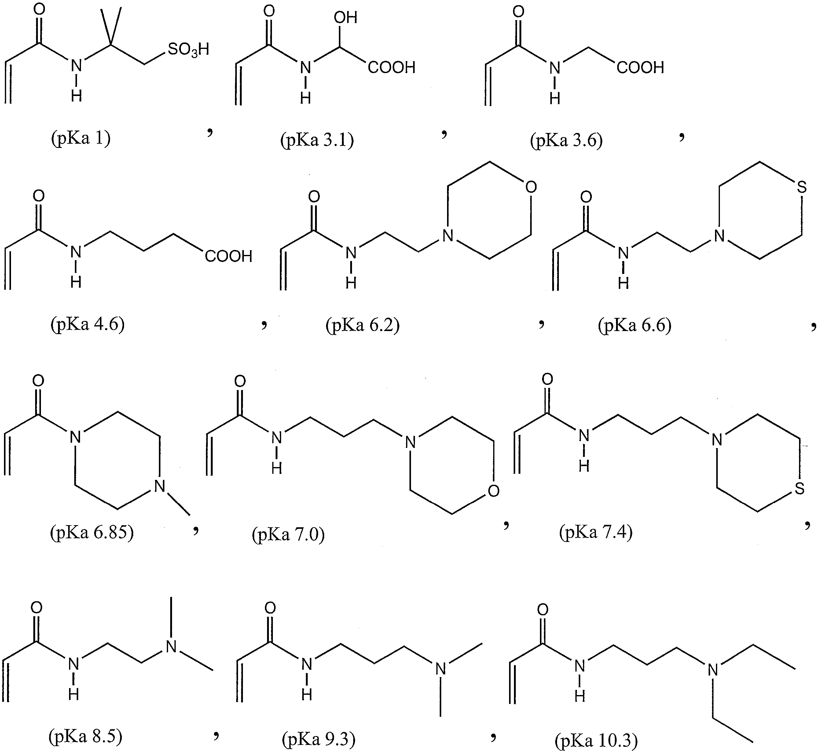
- the acrylamide buffer to be covalently bonded to the concentrated gel may be selected from acrylamide derivatives with known pKa. For example, but not limited to these, one or a plurality of buffers represented by the following general formula may be selected.
- an acrylamide buffer having a pKa in the range of 1.0 to 12.0 is covalently bound to the concentrated gel. More preferably, an acrylamide buffer having a pKa in the range of 6.2 to 8.5 is covalently bound.
- the acrylamide buffer in this range is covalently bound to the concentrated gel, so that the protein is sandwiched between chloride ions, which are the leading ions, and glycine, which is the trailing ions, and concentrates on the chloride ion boundary. .
- the acrylamide buffer covalently bonded to the concentrated gel is a buffer adjusted to the same pH as the pH buffer contained in the concentrated gel.
- the concentration of the acrylamide buffer covalently bonded to the concentrated gel is preferably in the range of 50 to 200 mM, more preferably in the range of 100 to 150 mM. By being in this range, it is possible to have a preferable buffer capacity and to concentrate the protein.
- the composition of the conventionally known concentrated gel can be applied to other compositions, and additives can be added as long as the function of the concentrated gel is not impaired.
- the separation gel contained in the polyacrylamide gel electrophoresis gel in Embodiment 1 has a pH adjusted to a range of 8.0 to 9.2. More preferably, the pH is adjusted to a range of 8.4 to 8.8, and as an example, the pH is adjusted to 8.8.
- the separation gel whose pH conditions are adjusted in this way, separation of the protein sample concentrated by the concentration gel occurs. Since the principle of separation is well known, description thereof is omitted here.
- the acrylamide buffer since the acrylamide buffer is cross-linked to the separation gel, the acrylamide buffer does not move from the separation gel to the concentrated gel. For this reason, a decrease in the concentration effect of the concentrated gel with the passage of time is suppressed, and heat generation during migration is also suppressed.
- an acrylamide buffer having a pKa in the range of 1.0 to 12.0 is covalently bound to the separation gel. More preferably, an acrylamide buffer having a pKa in the range of 8.5 to 9.3 is covalently bound.
- a high-resolution separation result can be obtained.
- the acrylamide buffer covalently bonded to the separation gel is a buffer adjusted to the same pH as the pH buffer solution contained in the separation gel.
- the concentration of the acrylamide buffer covalently bonded to the separation gel is preferably in the range of 50 to 200 mM, more preferably in the range of 100 to 150 mM. By being in this range, it is possible to have a preferable buffer capacity and to separate proteins.
- the acrylamide buffer covalently bonded to the separation gel may be selected from acrylamide derivatives having a known pKa.
- acrylamide derivatives having a known pKa For example, but not limited to these, one or a plurality of buffers represented by the following general formula may be selected.
- the composition of the separation gel known in the art can be applied to the other composition, and the separation gel can contain additives as long as the sample separation of the separation gel is not inhibited.
- FIG. 3 schematically shows a gel in which an acrylamide buffer is covalently bonded.
- R in FIG. 3 is a carboxyl group or a tertiary amine.
- an acrylamide buffer is crosslinked (covalently bonded) where acrylamide and bisacrylamide are crosslinked to form a branched molecular structure.
- the polyacrylamide gel electrophoresis gel in Embodiment 1 exists in a state where the concentrated gel and the separated gel containing the buffer solutions having different pHs are in contact with each other.
- the buffers are not mixed with each other. Therefore, there is no fear that the concentration effect of the concentrated gel is reduced by the buffer solution of the separation gel with the passage of time, and a polyacrylamide gel electrophoresis gel excellent in storage stability can be realized.
- the buffer solution contained in the concentrated gel and the separation gel has a charge under the pH conditions described above, but according to the first embodiment, the acrylamide buffer, which is a buffer contained in the buffer solution, is covalently bonded. Therefore, the buffer solution does not move in the gel due to voltage application. As a result, the current does not flow excessively in the gel, and undesired heat generation does not occur. Therefore, it is possible to provide a polyacrylamide gel electrophoresis gel capable of detecting a good electrophoretic separation pattern without causing gel expansion.
- the polyacrylamide gel electrophoresis gel in the first embodiment which is an SDS-PAGE gel, is prepared by providing a conventionally known method for preparing an SDS-PAGE gel. can do.
- FIG. 1 and FIG. 2 are perspective views of instruments used for producing a polyacrylamide gel electrophoresis gel in the first embodiment.
- FIG. 1 shows a state in which two gel plates 1 made of an insulating material are arranged so that the respective gel-forming surfaces are on the inside and are fastened with clips 2.
- a spacer (not shown) is provided between the two gel plates 1 to provide a gap corresponding to the thickness of the polyacrylamide gel electrophoresis gel in the first embodiment.
- the gap is filled with the gel solution using the tube 3.
- the spacers are disposed on the side portions and the lower portion of the two gel plates 1 and are not disposed on the upper portions of the two gel plates 1. As a result, the gel solution can be filled into the gap between the two gel plates 1 from above the two gel plates 1 via the tube 3.
- the gel solution is prepared as a separation gel solution and a concentrated gel solution, respectively.
- the separation gel solution is a conventionally known separation gel preparation acrylamide monomer solution (composition: 9.7% acrylamide, 0.3% bisacrylamide, 375 mM Tris-HCl (pH 8.8), 0.1% TEMED, 0.05% APS) and an acrylamide buffer (pKa 8.8) added to a concentration of 100 mM.
- the concentrated gel solution is a conventionally known concentrated acrylamide monomer solution (composition: It is prepared by adding acrylamide buffer (pKa 6.8) to a concentration of 100 mM to 2.91% acrylamide, 0.09% bisacrylamide, 0.05% TEMED, 0.03% APS).
- the separation gel solution is filled in the gap between the two gel plates 1.
- a polymerization initiator is added and filled.
- the filling amount is adjusted so that the liquid surface (upper surface) of the filled solution for separation gel is lower than the upper portions of the two gel plates 1.
- the solution is allowed to stand for a predetermined time to gel the separated gel solution.
- distilled water (not shown) is overlaid on the surface of the separation gel solution by a conventionally known method.
- the gelled state is shown in FIG. 2 (separation gel 4).
- the separation gel solution is gelled, the overlying distilled water is removed, and the concentrated gel solution is overlaid on the surface of the separation gel solution.
- a polymerization initiator is added and filled.
- the solution is allowed to stand for a predetermined time to gel the separated gel solution.
- the gelled state is shown in FIG. 2 (concentrated gel 5).
- the liquid surface (upper surface) of the concentrated gel solution is lower than the upper part of the gel plate 1, but the present invention is not limited to this, and the liquid of the concentrated gel solution After matching the surface (upper surface) and the upper part of the gel plate 1, a conventionally known comb for creating a well for sample application may be inserted.
- the solution is left for a predetermined time to gel the concentrated gel solution.
- the polyacrylamide gel electrophoresis gel in Embodiment 1 can be prepared by the above procedure.
- Electrophoresis Apparatus Next, an automated two-dimensional electrophoresis apparatus 400 will be described as an example of an electrophoresis apparatus according to the present invention.
- FIG. 4 shows a main configuration of the automated two-dimensional electrophoresis apparatus 400 according to the first embodiment.
- FIG. 4 is a perspective view showing a main part configuration of the automated two-dimensional electrophoresis apparatus 400.
- FIG. 4B shows a configuration in which the isoelectric focusing gel 200 is coupled to the support arm 431 via the holding unit 440.
- (C) in FIG. 4 is a cross-sectional view and a top view showing a configuration of a second-dimensional electrophoresis unit 420 used in the automated two-dimensional electrophoresis apparatus 400.
- the automated two-dimensional electrophoresis apparatus 400 includes a first-dimensional electrophoresis unit (first electrophoresis unit) 410 including an isoelectric focusing instrument on a fixing unit 401 serving as a base, and an SDS-PAGE.
- first electrophoresis unit first electrophoresis unit
- second electrophoretic unit second electrophoretic unit
- driving unit 404 that moves the fixing unit 401 and / or the supporting arm 431 to change the relative positions of both.
- the sample is first separated in the first direction (Y direction in FIG. 4) by the first-dimensional electrophoresis unit 410, and after the buffer solution is equilibrated, the second-dimensional electrophoresis is performed.
- the part 420 separates in the second direction (X direction in FIG. 4). This is realized by the driving means 404 holding the support arm 431 so as to be movable in the X-axis direction and the Z-axis direction.
- the first-dimensional electrophoresis unit 410 is provided with a plurality of tanks. The first-dimensional electrophoresis unit 410 will be further described with reference to FIG.
- FIG. 5 is a sectional view of the automated two-dimensional electrophoresis apparatus 400.
- the first-dimensional electrophoresis unit 410 has a configuration in which a plurality of tanks 411 and 412 are provided in a single insulator.
- the first reagent tank 411 is for storing reagents necessary for the process until the first-dimensional separation
- the second reagent tank 412 is after the first-dimensional separation and before the second-dimensional separation. It is for storing necessary reagents.
- the first reagent tank 411 includes a gel arrangement tank 411a, a sample tank 411b, a swelling tank 411c, and a first separation tank 411d as an isoelectric focusing instrument.
- the second reagent tank 412 includes a first equilibration tank 412a, a staining tank 412b, a washing tank 412c, and a second equilibration tank 412d.
- the first equilibration tank 412a is preferably provided to store a buffer solution for replacing the buffer solution used for the first direction separation and increasing the efficiency of staining performed after the first direction separation.
- the washing tank 412c is preferably provided for storing a buffer solution for washing excess fluorescent dye attached in the staining tank 412b in which the fluorescent dye is stored.
- the second equilibration tank 412d stores a reagent preferable for performing the second direction separation.
- a reagent for reducing the protein of the isoelectric focusing gel 200 and a reagent for converting the protein into SDS are stored.
- a buffer solution, a surfactant, an enzyme, an interacting substance, or the like may be stored depending on the second direction separation method.
- the driving means 404 first drives the support arm 431 to the desired X position of the gel placement tank 411a, and then lowers the support arm 431 to the desired Z position. Then, adsorption
- the adsorption control to the support arm 431 can be automatically controlled by using, for example, an electromagnetic valve.
- the drive unit 404 moves the holding body 40 with the gel adsorbed on the support arm 431 in the direction of the arrow 402 in FIG. 5, whereby the isoelectric focusing gel 200 is moved to the first-dimensional electrophoresis unit 410. In each of the tanks provided, a desired process is performed, and subsequently, it is transported to the second-dimensional electrophoresis unit 420.
- the first-dimensional electrophoresis unit 410 a voltage is applied to the isoelectric focusing gel 200, the step of introducing the sample into the isoelectric focusing gel 200, the step of swelling the isoelectric focusing gel 200, and the isoelectric focusing gel 200.
- the step of separating the sample in the first direction, the step of staining the separated sample in the isoelectric focusing gel 200, and the step of equilibrating to the environment in the second-dimensional electrophoresis unit 420 are performed.
- the swelling speed can be improved by separately adding the sample to the isoelectric focusing gel and swelling the isoelectric focusing gel 200.
- the first separation tank 411d which is an isoelectric focusing instrument, is filled with a buffer solution necessary for isoelectric focusing (first-dimensional separation). However, when the reagent stored in the swelling tank 411c contains a buffer solution necessary for the first-dimensional separation, the first separation tank 411d may not be filled with the buffer solution necessary for the first-dimensional separation.
- the sample in the isoelectric focusing gel 200 is separated by applying a voltage to the pair of electrodes (not shown) by the first voltage applying unit 405.
- the second-dimensional electrophoresis unit 420 includes the polyacrylamide gel electrophoresis gel (SDS-PAGE gel) 10 described above, and is transported from the first-dimensional electrophoresis unit 410 in the SDS-PAGE gel 10.
- the separated sample contained in the isoelectric focusing gel 200 is further separated (SDS-PAGE) in a second direction different from the first direction.
- the second-dimensional electrophoretic unit 420 includes a first buffer solution provided in the lower insulating unit through the upper insulating plate 422 on the insulating unit 420a obtained by superimposing the lower insulating plate 421 and the upper insulating plate 422, which are gel plates. It has a tank 428a and a second buffer tank 428b.
- the lower insulating plate 421 is provided with a gel storage portion 10 ′ for covering and storing the SDS-PAGE gel 10 between the lower insulating plate 421 and the upper insulating plate 422.
- the SDS-PAGE gel 10 accommodated in the gel accommodating portion 10 ′ is covered with an insulating portion 420 a composed of a lower insulating plate 421 and an upper insulating plate 422, and the first opening 425 and the second opening 426 have the insulating portion 420 a of the insulating portion 420 a. Can contact the outside.
- the first opening 425 and the second opening 426 face the first buffer tank 428a and the second buffer tank 428b provided in the second-dimensional electrophoresis unit 420, respectively.
- the first buffer tank 428a and the second buffer tank 428b include the SDS-PAGE gel 10 and the first opening 425 stored in the gel storage section 10 ′.
- a first buffer solution and a second buffer solution (solution containing a cathode buffer) that are in contact with each other through the second opening 426 are filled.
- the first buffer tank 428a and the second buffer tank 428b are provided with a first electrode 429a and a second electrode 429b, and SDS is applied by the second voltage applying means 406 via the first electrode 429a and the second electrode 429b.
- SDS is applied by the second voltage applying means 406 via the first electrode 429a and the second electrode 429b.
- a voltage is applied to the PAGE gel 10
- a current flows from the first opening 425 toward the second opening 426.
- the separated sample in the isoelectric focusing gel 200 and the molecular weight marker are developed / separated from the second opening 426 toward the first opening 425.
- the cathode buffer of the solution containing the cathode buffer filled in the second buffer bath 428b includes front ions (for example, chlorine ions) and trailing ions (glycine, tricine, etc.).
- front ions and trailing ions By including front ions and trailing ions in the cathode buffer, a band concentration effect can be obtained.
- a buffer that does not contain front ions and trailing ions can also be used as a cathode buffer (for example, MOPS-based and MES-based buffers). Even a buffer that does not contain front ions and trailing ions has the above-described effect of suppressing heat generation.
- a buffer containing front ions and trailing ions as a cathode buffer.
- the buffer concentration of the cathode buffer is adjusted to a range of 25 to 50 mM.
- the buffer concentration of the gel for polyacrylamide gel electrophoresis is adjusted to a range of 150 to 500 mM and setting it higher than the buffer concentration of the cathode buffer, zone electrophoresis becomes possible, and the protein band is sharpened. There is an effect to.
- the width of the opening penetrating the upper insulating plate 422 in the second buffer solution tank 428b is the groove width of the corresponding lower insulating plate 421. Wider. Due to this difference, as shown in FIG. 5, the isoelectric focusing gel 200 of the gel-attached holding body 40 inserted from the second opening 426 and the SDS-PAGE gel 10 can be brought into close contact with each other. The sample in the isoelectric focusing gel 200 after the original electrophoresis can be successfully separated by SDS-PAGE.
- the insulating portion 420a covering the SDS-PAGE gel 10 causes the isoelectric focusing gel 200 and the SDS-PAGE gel 10 to adhere to each other.
- Such a portion may be the second opening 426, or a further opening 426 ′ may be provided between the first opening 425 and the second opening 426.
- the SDS-PAGE gel 10 protrudes from the second opening 426. More preferably, the protruding SDS-PAGE gel 10 has no irregularities. In the case where the SDS-PAGE gel 10 does not protrude from the second opening 426, an adhesive member for bringing the isoelectric focusing gel 200 and the SDS-PAGE gel 10 into close contact with the second opening 426 ( (Not shown) may be provided.
- Preferred adhesive members include, but are not limited to, agarose, low viscosity (about 1-3%) gels such as acrylamide, and high viscosity liquids such as glycerin, polyethylene glycol, and hydroxypropyl cellulose.
- the fixing to these fixing means 401 is performed. It is preferable that it is detachable.
- a pinch fixing mechanism, a magnetic force fixing mechanism, and an electrostatic adsorption mechanism can be cited in addition to the vacuum adsorption mechanism, but not limited thereto.
- a cooling means 409 (for example, a heat radiating means) shown in FIG. 5 may be provided immediately below the fixing means 401.
- the cooling means 409 By employing the cooling means 409, the temperature of the first-dimensional electrophoresis unit 410 and the second-dimensional electrophoresis unit 420 during electrophoresis can be kept constant.
- an automated two-dimensional electrophoresis apparatus has been described as an electrophoresis apparatus.
- the present invention is not limited to a two-dimensional electrophoresis apparatus, and an electrophoresis apparatus that performs only SDS-PAGE (general) Of course, a typical SDS-PAGE apparatus may also be included.
- the automated two-dimensional electrophoresis apparatus described in the first embodiment has a form in which the SDS-PAGE gel 10 is disposed (horizontally placed) along a horizontal plane, but the SDS-PAGE gel is arranged along a vertical plane. May be arranged (vertically placed).
- Embodiment 1 the mode in which the acrylamide buffer is covalently bonded to the gel in both the separation gel and the concentration gel has been described.
- the present invention is not limited to this.
- the acrylamide buffer is covalently bound to the gel only in the concentrated gel. That is, in Embodiment 3, the acrylamide buffer is not covalently bonded to the separation gel.
- the acrylamide buffer covalently bonded to the concentrated gel does not move to the separated gel. Therefore, even if the time has elapsed, since the buffer having a predetermined pKa remains in the concentrated gel, it is possible to suppress the pH of the concentrated gel from fluctuating and suppress the reduction of the concentration effect in the concentrated gel. . Further, since the buffer does not move in the concentrated gel, heat generation can be suppressed.
- Embodiment 1 the mode in which the acrylamide buffer is covalently bonded to the gel in both the separation gel and the concentration gel has been described.
- the present invention is not limited to this.
- the acrylamide buffer is covalently bonded to the gel only in the separation gel. That is, in Embodiment 3, the acrylamide buffer is not covalently bonded to the concentrated gel.
- the acrylamide buffer covalently bonded to the separation gel does not move to the concentration gel. Therefore, even if time passes, the concentrated gel is not mixed with a buffer having a different pH from the separated gel, and the pH of the concentrated gel is prevented from fluctuating and the reduction of the concentration effect in the concentrated gel is suppressed. be able to. Moreover, since the buffer does not move in the separation gel, heat generation can be suppressed.
- a polyacrylamide gel electrophoresis gel (SDS-PAGE 10) according to embodiment 1 of the present invention includes a concentrated gel 5 and a separation gel 4 that is adjusted to a pH different from that of the concentrated gel.
- An acrylamide buffer is covalently bonded to at least one of the separation gels 4.
- the acrylamide buffer is not released from the gel to which the acrylamide buffer is covalently bonded.
- the covalently bonded acrylamide buffer is an acrylamide derivative having a buffering action.
- the polyacrylamide gel electrophoresis gel according to the first aspect of the present invention can maintain the concentration effect even if time passes.
- the gel can be loaded into the apparatus on the side where the electrophoresis apparatus is manufactured, which can contribute to the automation of electrophoresis.
- the covalently bonded acrylamide buffer does not move in the gel even when a voltage is applied. For this reason, an excessive current does not flow in the gel, and no undesirable heat generation occurs. Therefore, it is possible to provide a polyacrylamide gel electrophoresis gel capable of detecting a good electrophoretic separation pattern without causing gel expansion.
- the polyacrylamide gel electrophoresis gel of the present invention in which the above-mentioned problems are solved can be said to be superior to the conventional electrophoresis gel.
- the polyacrylamide gel electrophoresis gel according to aspect 2 of the present invention is the above-described aspect 1, wherein the concentrated gel 5 is cross-linked with an acrylamide buffer having a pKa in the range of 6.2 to 8.5. preferable.
- an acrylamide buffer having a pKa in the range of 6.2 to 8.5. preferable since the dissociation degree of glycine contained in the cathode buffer is low, the movement to the anode is delayed, and the protein that moves in the concentrated gel is concentrated.
- the separation gel 4 is crosslinked with an acrylamide buffer having a pKa in the range of 8.5 to 9.3. It is preferable. By cross-linking the acrylamide buffer of pKa in this range, proteins moving in the separation gel are separated by the molecular sieving effect.
- the polyacrylamide gel electrophoresis gel according to aspect 4 of the present invention is the above-described separation gel 4 wherein the pH of the concentrated gel 5 is adjusted in the range of 6.6 to 7.5 in the above aspect 1 or 3.
- the pH is preferably adjusted to a range of 8.4 to 8.8.
- the polyacrylamide gel electrophoresis gel according to Aspect 5 of the present invention can be a sodium dodecyl sulfate-polyacrylamide gel electrophoresis gel according to Aspects 1 to 4.
- An electrophoresis apparatus (automated two-dimensional electrophoresis apparatus 400) according to Aspect 6 of the present invention includes a polyacrylamide gel electrophoresis gel according to any one of Aspects 1 to 4, a cathode (second electrode 429b), and the above The anode (first electrode 429a) disposed on the opposite side of the cathode (second electrode 429b) with respect to the polyacrylamide gel electrophoresis gel, and the cathode side (first electrode) of the polyacrylamide gel electrophoresis gel And a cathode buffer added to the two buffer baths 428b).
- the cathode buffer may include front ions and trailing ions.
- the electrophoresis apparatus is the above-described aspect 6 or 7, wherein the buffer concentration of the cathode buffer is adjusted to a range of 20 to 50 mM, and the buffer concentration of the polyacrylamide gel electrophoresis gel is , May be adjusted to a range of 150 to 500 mM.
- Zone electrophoresis is effective by setting the buffer concentration of the gel for polyacrylamide gel electrophoresis higher than that of the cathode buffer.
- the electrophoretic device performs the first electrophoretic section (first-dimensional electrophoretic section 410) that performs the first-dimensional electrophoresis and the second-dimensional electrophoretic. It has a 2nd electrophoresis part (2D electrophoretic part 420), and the gel for electrophoresis of the above-mentioned 2nd electrophoresis part may be the above-mentioned polyacrylamide gel electrophoresis gel.
- the polyacrylamide gel electrophoresis gel having the above-described effects is provided as the electrophoresis gel of the second electrophoresis section, and complete automation of two-dimensional electrophoresis can be realized.
- the electrophoresis gel of the second electrophoresis section had to be prepared by the electrophoresis operator for the reasons described above. That is, even if a part of the two-dimensional electrophoresis apparatus can be automated, the preparation of the gel has to be performed by the person performing the electrophoresis. However, according to the above configuration, the gel can be placed in the apparatus before (much) the electrophoresis is performed. Therefore, the work performed by the practitioner is only sample adjustment, for example, and all operations relating to electrophoresis can be automated by the apparatus.
- Sample protein was prepared from mouse liver tissue. First, 0.4 g of a sample was weighed from mouse liver tissue while avoiding blood vessels and blood pools as much as possible, and placed in a 5 mL glass Teflon (registered trademark) homogenizer cooled on ice. Add 5-6 volumes (2 mL) of lysis buffer (50 mM Tris HCl (pH 7.6), 20% glycerol, 0.3 M NaCl) and protease inhibitor cocktail cooled to 4 ° C. to the sample in the homogenizer, Triturated on ice (3000-4000 rpm). Thereafter, it was centrifuged at 1000 ⁇ g for 10 minutes at 4 ° C. After collecting the supernatant, it was centrifuged at 16000 ⁇ g for 30 minutes at 4 ° C. The supernatant was collected again, protein quantification was performed, the concentration was calculated, and stored at ⁇ 80 ° C.
- lysis buffer 50 mM Tris HCl (pH 7.6), 20%
- the protein was purified by desalting and concentration by acetone precipitation.
- a protein solution sample obtained from mouse liver tissue was placed in a 1.5-2.0 mL microtube.
- 8 to 9 times the amount of cold acetone ( ⁇ 20 ° C.) was added and kept at ⁇ 20 ° C. for about 2 hours.
- the supernatant (acetone fraction) was discarded, and the tube was left for 2 to 3 minutes with the lid of the tube open, to blow off the acetone.
- a gel for SDS-PAGE (10) was prepared using a gel preparation device as shown in FIG. First, two glass plates (1) sandwiching a 1 mm spacer and packing were fixed with a clip (2). From the injection tube (3), between the glass plates, an acrylamide monomer solution (9.7% acrylamide, 0.3% bisacrylamide, 375 mM Tris-HCl (pH 8.8), 0.1) containing Tris buffer at pH 8.8. % TEMED, 0.05% APS) was added to fill about 70%, and then the surface layer was overlaid with water and polymerized at room temperature for 30 minutes to form a separation gel.
- an acrylamide monomer solution (9.7% acrylamide, 0.3% bisacrylamide, 375 mM Tris-HCl (pH 8.8), 0.1) containing Tris buffer at pH 8.8. % TEMED, 0.05% APS
- acrylamide monomer solution containing acrylamide buffer of pKa 6.8 (2.91% acrylamide, 0.09% bisacrylamide, 100 mM acrylamide buffer (pKa 6.8), 0.05, % TEMED, 0.03% APS) and covering with a flat comb, the surface of the acrylamide monomer solution is polymerized for about 2 hours at room temperature to form a concentrated gel 5 did.
- a double-layered SDS-PAGE gel having a concentrated gel and a separation gel was prepared (see FIG. 2).
- Two-dimensional electrophoresis Contrast with one-layer gel
- Two-dimensional electrophoresis was performed with Auto2D manufactured by Sharp Manufacturing System. Examples include: As a comparative example, a commercially available single layer (pH 8.8) SDS-PAGE gel prepared in consideration of storage stability was used.
- two-dimensional electrophoresis was performed using an antibody (Trastuzumab) as a sample.
- the first-dimensional electrophoresis conditions were as follows. Step 1: 200V, 5 minutes constant Step 2: 1000V, 5 minutes linear gradient Step 3: 1000V, 5 minutes constant Step 4: 4000V, 10 minutes linear gradient Step 5: 4000V, 10 minutes constant Step 6: 7000V, 10 minutes linear gradient Step 7: 7000V, 20 Fixed for a minute Thereafter, two-dimensional electrophoresis was performed as follows. Step 1: 10 mA, 10 minutes constant Step 2: 20 mA, 35 minutes Two-dimensional electrophoresis results are shown in FIG. In the SDS-PAGE gel according to the comparative example ((b) in FIG.
- the present invention can be used for an electrophoresis apparatus that performs SDS-PAGE and a two-dimensional electrophoresis apparatus, and can also be used for, for example, drug discovery research and development, and can also be applied to medical equipment for diagnosis. Is possible.
Landscapes
- Health & Medical Sciences (AREA)
- Life Sciences & Earth Sciences (AREA)
- Chemical & Material Sciences (AREA)
- Molecular Biology (AREA)
- Electrochemistry (AREA)
- Chemical Kinetics & Catalysis (AREA)
- Physics & Mathematics (AREA)
- Analytical Chemistry (AREA)
- Biochemistry (AREA)
- General Health & Medical Sciences (AREA)
- General Physics & Mathematics (AREA)
- Immunology (AREA)
- Pathology (AREA)
- Dispersion Chemistry (AREA)
- Peptides Or Proteins (AREA)
Abstract
Description
本発明に係るポリアクリルアミドゲル電気泳動用ゲルおよび当該ゲルの作製方法の一実施形態、並びに当該ゲルを備えた電気泳動装置の一実施形態を以下に説明する。
本発明に係るポリアクリルアミドゲル電気泳動用ゲルは、タンパク質の分離は起こらず濃縮を受ける濃縮ゲル(スタッキングゲル)と、当該濃縮ゲルとは異なるpHに調整されたタンパク質の分離がおこなわれる分離ゲルとを含有する。なお、本発明におけるポリアクリルアミドゲル電気泳動用ゲルは、濃縮ゲルおよび分離ゲルのほかに他のゲル(層)を含み得る。
本実施形態1におけるポリアクリルアミドゲル電気泳動用ゲルに含有される濃縮ゲルは、pHが、pH6.0~pH8.8の範囲に調整されている。より好ましくは、pH6.6~pH7.5の範囲に調整され、一例としてpH6.8に調整されている。このようにpH条件が調整された濃縮ゲルでは、タンパク質は分離されずに濃縮を受ける。なお、濃縮の原理は周知であるため、ここでの説明は省略する。

本実施形態1におけるポリアクリルアミドゲル電気泳動用ゲルに含有される分離ゲルは、pHが8.0~9.2の範囲に調整されている。より好ましくは、pHが8.4~8.8の範囲に調整され、一例としてpH8.8に調整されている。このようにpH条件が調整された分離ゲルでは、濃縮ゲルによって濃縮されたタンパク質サンプルの分離が起こる。なお、分離の原理は周知であるためここでの説明は省略する。
SDS-PAGE用ゲルである本実施形態1におけるポリアクリルアミドゲル電気泳動用ゲルは、従来周知のSDS-PAGE用ゲルの作製方法を提供して作製することができる。
次に、本発明に係る電気泳動装置の一実施形態として、自動化二次元電気泳動装置400を例に挙げて説明する。
一次元目電気泳動部410には、複数の槽が設けられている。一次元目電気泳動部410について、図5を用いて更に説明する。
二次元目電気泳動部420には、上述したポリアクリルアミドゲル電気泳動用ゲル(SDS-PAGE用ゲル)10が具備されており、SDS-PAGE用ゲル10において、一次元目電気泳動部410から搬送された等電点電気泳動ゲル200に含まれた分離サンプルが、第1方向と異なる第2方向にさらに分離(SDS-PAGE)される。
本発明の他の実施形態を説明すれば、以下のとおりである。なお、説明の便宜上、前記実施形態にて説明した部材と同じ機能を有する部材については説明を省略する。
本発明の他の実施形態を説明すれば、以下のとおりである。なお、説明の便宜上、前記実施形態にて説明した部材と同じ機能を有する部材については説明を省略する。
本発明の態様1に係るポリアクリルアミドゲル電気泳動用ゲル(SDS-PAGE用10)は、濃縮ゲル5および上記濃縮ゲルとは異なるpHに調整されている分離ゲル4を含み、上記濃縮ゲル5および上記分離ゲル4のうちの少なくとも一方には、アクリルアミドバッファーが共有結合されていることを特徴としている。
マウス肝臓組織から試料タンパク質を調製した。まず、マウス肝臓組織から、血管および血液溜をなるべく避けて0.4gの試料を秤取り、氷上で冷却した5mLガラステフロン(登録商標)ホモジナイザーに入れた。ホモジナイザー内の試料に、4℃に冷却した5~6倍量(2mL)の溶解バッファー(50mMトリスHCl(pH7.6)、20%グリセロール、0.3M NaCl)およびプロテアーゼ阻害剤カクテルを添加し、氷上で摩砕した(3000~4000rpm)。その後、1000×gで10分間、4℃で遠心分離した。上清を回収した後、16000×gで30分間、4℃で遠心分離した。再度上清を回収し、タンパク質定量を行い、濃度を算定した後、-80℃で保存した。
図1に示すようなゲル作製器具を用いて、SDS-PAGE用ゲル(10)を作製した。まず、1mmのスペーサーおよびパッキンを挟んだ2枚のガラス板(1)をクリップ(2)によって固定した。注入管(3)から、ガラス板の間に、pH8.8のトリス緩衝液を含むアクリルアミドモノマー溶液(9.7%アクリルアミド、0.3%ビスアクリルアミド、375mM Tris-HCl(pH8.8)、0.1%TEMED、0.05%APS)を添加して、約7割まで充填した後、表層に水を重層して、30分間室温にて重合を行い、分離ゲルを形成した。
シャープマニファクチュアリングシステム社製のAuto2Dにより二次元電気泳動を行なった。実施例としては、2.において作製した二層のSDS-PAGE用ゲルを用い、比較例としては、保存性を考慮して作製されている市販の一層(pH8.8)のSDS-PAGE用ゲルを用いた。
Step1:200V,5分間一定
Step2:1000V,5分間リニアグラジエント
Step3:1000V,5分間一定
Step4:4000V,10分間リニアグラジエント
Step5:4000V,10分間一定
Step6:7000V,10分間リニアグラジエント
Step7:7000V,20分間一定
その後、2次元電気目電気泳動は、次の通りとした。
Step1:10mA、10分間一定
Step2:20mA、35分間
二次元電気泳動結果を図7に示す。比較例に係るSDS-PAGE用ゲル(図7の(b))では、スポットが縦に伸びる現象が発生していた。これは、非還元条件下の抗体が約160kDaと非常に大きな分子であることに起因する。一方、実施例に係るSDS-PAGE用ゲル(図7の(a))では、濃縮ゲルにおいて濃縮効果が得られるため、抗体を試料とした場合でも、スポットが縦に伸びる現象を抑制することができた(図7の(a))。
2 クリップ
3 チューブ
4 分離ゲル
5 濃縮ゲル
10 SDS-PAGE用ゲル(ポリアクリルアミドゲル電気泳動用ゲル)
10’ ゲル収納部
40 ゲル付き保持体
200 等電点電気泳動ゲル
400 自動化二次元電気泳動装置
410 一次元目電気泳動部(第一泳動部)
411 第一試薬槽
412 第2試薬槽
420 二次元目電気泳動部(第二泳動部)
421 下部絶縁板
422 上部絶縁板
428a 第1緩衝液槽
428b 第2緩衝液槽
429a 第1電極
429b 第2電極
Claims (9)
- 濃縮ゲルおよび上記濃縮ゲルとは異なるpHに調整されている分離ゲルを含み、
上記濃縮ゲルおよび上記分離ゲルのうちの少なくとも一方には、アクリルアミドバッファーが共有結合されていることを特徴とするポリアクリルアミドゲル電気泳動用ゲル。 - 上記濃縮ゲルに、pKaが、6.2~8.5の範囲であるアクリルアミドバッファーが架橋されていることを特徴とする請求項1に記載のポリアクリルアミドゲル電気泳動用ゲル。
- 上記分離ゲルに、pKaが、8.5~9.3の範囲であるアクリルアミドバッファーが架橋されていることを特徴とする請求項1または2に記載のポリアクリルアミドゲル電気泳動用ゲル。
- 上記濃縮ゲルのpHは、6.6~7.5の範囲に調整されており、
上記分離ゲルのpHは、8.4~8.8の範囲に調整されていることを特徴とする請求項1~3の何れか一項に記載のポリアクリルアミドゲル電気泳動用ゲル。 - ドデシル硫酸ナトリウム-ポリアクリルアミドゲル電気泳動用ゲルであることを特徴とする請求項1から4までの何れか1項に記載のポリアクリルアミドゲル電気泳動用ゲル。
- 請求項1~5の何れか一項に記載のポリアクリルアミドゲル電気泳動用ゲルと、
陰極と、
上記ポリアクリルアミドゲル電気泳動用ゲルに対して、上記陰極とは反対側に配置された陽極と、
上記ポリアクリルアミドゲル電気泳動用ゲルの上記陰極側に添加される陰極バッファーと、を備えている電気泳動装置。 - 上記陰極バッファーは、フロントイオンおよびトレイリングイオンを含んでいることを特徴とする請求項6に記載の電気泳動装置。
- 上記陰極バッファーのバッファー濃度は、20~50mMの範囲に調整されており、
上記ポリアクリルアミドゲル電気泳動用ゲルのバッファー濃度は、150~500mMの範囲に調整されていることを特徴とする請求項6または7に記載の電気泳動装置。 - 一次元目の電気泳動をおこなう第一泳動部と、二次元目の電気泳動をおこなう第二泳動部とを有し、
上記第二泳動部の電気泳動用ゲルが上記ポリアクリルアミドゲル電気泳動用ゲルであることを特徴とする請求項6から8までの何れか1項に記載の電気泳動装置。
Priority Applications (2)
| Application Number | Priority Date | Filing Date | Title |
|---|---|---|---|
| JP2015553473A JP6200967B2 (ja) | 2013-12-16 | 2014-12-04 | ポリアクリルアミドゲル電気泳動用ゲルおよび当該ゲルを備えた電気泳動装置 |
| US15/103,362 US20160334364A1 (en) | 2013-12-16 | 2014-12-04 | Gel for use in polyacrylamide gel electrophoresis and electrophoresis device using said gel |
Applications Claiming Priority (2)
| Application Number | Priority Date | Filing Date | Title |
|---|---|---|---|
| JP2013259571 | 2013-12-16 | ||
| JP2013-259571 | 2013-12-16 |
Publications (1)
| Publication Number | Publication Date |
|---|---|
| WO2015093301A1 true WO2015093301A1 (ja) | 2015-06-25 |
Family
ID=53402650
Family Applications (1)
| Application Number | Title | Priority Date | Filing Date |
|---|---|---|---|
| PCT/JP2014/082106 Ceased WO2015093301A1 (ja) | 2013-12-16 | 2014-12-04 | ポリアクリルアミドゲル電気泳動用ゲルおよび当該ゲルを備えた電気泳動装置 |
Country Status (3)
| Country | Link |
|---|---|
| US (1) | US20160334364A1 (ja) |
| JP (1) | JP6200967B2 (ja) |
| WO (1) | WO2015093301A1 (ja) |
Citations (5)
| Publication number | Priority date | Publication date | Assignee | Title |
|---|---|---|---|---|
| JP2005308450A (ja) * | 2004-04-19 | 2005-11-04 | Enbitekku Japan:Kk | ゲル電気泳動分析システム、ゲル電気泳動分析方法および陰極バッファー溶液 |
| JP2006162405A (ja) * | 2004-12-07 | 2006-06-22 | National Institute Of Advanced Industrial & Technology | 二次元電気泳動方法 |
| WO2010008008A1 (ja) * | 2008-07-15 | 2010-01-21 | 凸版印刷株式会社 | 電気泳動器具および電気泳動方法 |
| JP2013040792A (ja) * | 2011-08-11 | 2013-02-28 | Sharp Corp | 電気泳動ゲルチップならびにその製造方法および製造キット |
| WO2013133083A1 (ja) * | 2012-03-05 | 2013-09-12 | シャープ株式会社 | 電気泳動用ゲルの製造方法および電気泳動用ゲルの製造装置 |
Family Cites Families (2)
| Publication number | Priority date | Publication date | Assignee | Title |
|---|---|---|---|---|
| JP2003004702A (ja) * | 2001-06-15 | 2003-01-08 | Bio Meito:Kk | 高分解能電気泳動用ゲルの製造方法 |
| KR20100058499A (ko) * | 2007-08-17 | 2010-06-03 | 하이모 가부시키가이샤 | 전기영동용 프리캐스트 겔, 그 제조방법 및 그 사용방법 |
-
2014
- 2014-12-04 WO PCT/JP2014/082106 patent/WO2015093301A1/ja not_active Ceased
- 2014-12-04 US US15/103,362 patent/US20160334364A1/en not_active Abandoned
- 2014-12-04 JP JP2015553473A patent/JP6200967B2/ja active Active
Patent Citations (5)
| Publication number | Priority date | Publication date | Assignee | Title |
|---|---|---|---|---|
| JP2005308450A (ja) * | 2004-04-19 | 2005-11-04 | Enbitekku Japan:Kk | ゲル電気泳動分析システム、ゲル電気泳動分析方法および陰極バッファー溶液 |
| JP2006162405A (ja) * | 2004-12-07 | 2006-06-22 | National Institute Of Advanced Industrial & Technology | 二次元電気泳動方法 |
| WO2010008008A1 (ja) * | 2008-07-15 | 2010-01-21 | 凸版印刷株式会社 | 電気泳動器具および電気泳動方法 |
| JP2013040792A (ja) * | 2011-08-11 | 2013-02-28 | Sharp Corp | 電気泳動ゲルチップならびにその製造方法および製造キット |
| WO2013133083A1 (ja) * | 2012-03-05 | 2013-09-12 | シャープ株式会社 | 電気泳動用ゲルの製造方法および電気泳動用ゲルの製造装置 |
Also Published As
| Publication number | Publication date |
|---|---|
| JP6200967B2 (ja) | 2017-09-20 |
| JPWO2015093301A1 (ja) | 2017-03-16 |
| US20160334364A1 (en) | 2016-11-17 |
Similar Documents
| Publication | Publication Date | Title |
|---|---|---|
| Dawod et al. | Recent advances in protein analysis by capillary and microchip electrophoresis | |
| Hajba et al. | Recent advances in column coatings for capillary electrophoresis of proteins | |
| Krebs et al. | Strategies for capillary electrophoresis: method development and validation for pharmaceutical and biological applications—updated and completely revised edition | |
| Walker | SDS polyacrylamide gel electrophoresis of proteins | |
| Rabilloud et al. | Sample application by in‐gel rehydration improves the resolution of two‐dimensional electrophoresis with immobilized pH gradients in the first dimension | |
| Copeland | Methods for protein analysis | |
| Creamer et al. | Recent advances in the analysis of therapeutic proteins by capillary and microchip electrophoresis | |
| JP5977269B2 (ja) | 試料の分析方法及びそれに用いる溶液 | |
| JP5619165B2 (ja) | 高速高分離能のゲル電気泳動のためのシステム | |
| JP2003529762A (ja) | 溶液等電点電気泳動による荷電分子解析の方法および装置 | |
| JP2004510168A (ja) | 電気泳動システム | |
| US20080067079A1 (en) | Method of Analyzing Sample and Analyzing Apparatus | |
| JP2011080842A (ja) | サンプル分離吸着器具 | |
| JP5509060B2 (ja) | 電気泳動法によるヘモグロビンの分析方法 | |
| JP5539731B2 (ja) | 電気泳動法のための安定化媒体及び分離媒体 | |
| JP6200967B2 (ja) | ポリアクリルアミドゲル電気泳動用ゲルおよび当該ゲルを備えた電気泳動装置 | |
| Bergmann et al. | Potential of on-line isotachophoresis-capillary zone electrophoresis with hydrodynamic counterflow in the analysis of various basic proteins and recombinant human interleukin-3 | |
| Benavente et al. | Determination of human erythropoietin by on-line immunoaffinity capillary electrophoresis: a preliminary report | |
| Shimura | Capillary isoelectric focusing | |
| US20140114053A1 (en) | Electrophoresis Separation Methods | |
| Harper et al. | Comparing complex protein samples using two‐dimensional polyacrylamide gels | |
| Casero et al. | Preparative isoelectric focusing in immobilized pH gradients IV. Recovery of proteins from Immobiline matrices into ion‐exchange resins | |
| JP7062324B1 (ja) | 脂質タンパク質複合体を含む多検体試料を分析するための電気泳動用スラブ型ポリアクリルアミドゲル及びその方法 | |
| US7347922B2 (en) | Multi-dimensional proteomic analysis method | |
| Houri et al. | Pulsed field electrophoresis for the separation of protein‐sodium dodecyl sulfate‐complexes in polyacrylamide gels |
Legal Events
| Date | Code | Title | Description |
|---|---|---|---|
| 121 | Ep: the epo has been informed by wipo that ep was designated in this application |
Ref document number: 14871461 Country of ref document: EP Kind code of ref document: A1 |
|
| ENP | Entry into the national phase |
Ref document number: 2015553473 Country of ref document: JP Kind code of ref document: A |
|
| WWE | Wipo information: entry into national phase |
Ref document number: 15103362 Country of ref document: US |
|
| NENP | Non-entry into the national phase |
Ref country code: DE |
|
| 122 | Ep: pct application non-entry in european phase |
Ref document number: 14871461 Country of ref document: EP Kind code of ref document: A1 |