WO2015092987A1 - 高強度溶融亜鉛めっき鋼板およびその製造方法 - Google Patents
高強度溶融亜鉛めっき鋼板およびその製造方法 Download PDFInfo
- Publication number
- WO2015092987A1 WO2015092987A1 PCT/JP2014/005982 JP2014005982W WO2015092987A1 WO 2015092987 A1 WO2015092987 A1 WO 2015092987A1 JP 2014005982 W JP2014005982 W JP 2014005982W WO 2015092987 A1 WO2015092987 A1 WO 2015092987A1
- Authority
- WO
- WIPO (PCT)
- Prior art keywords
- less
- martensite
- area ratio
- steel sheet
- hot
- Prior art date
- Legal status (The legal status is an assumption and is not a legal conclusion. Google has not performed a legal analysis and makes no representation as to the accuracy of the status listed.)
- Ceased
Links
Classifications
-
- C—CHEMISTRY; METALLURGY
- C21—METALLURGY OF IRON
- C21D—MODIFYING THE PHYSICAL STRUCTURE OF FERROUS METALS; GENERAL DEVICES FOR HEAT TREATMENT OF FERROUS OR NON-FERROUS METALS OR ALLOYS; MAKING METAL MALLEABLE, e.g. BY DECARBURISATION OR TEMPERING
- C21D9/00—Heat treatment, e.g. annealing, hardening, quenching or tempering, adapted for particular articles; Furnaces therefor
- C21D9/46—Heat treatment, e.g. annealing, hardening, quenching or tempering, adapted for particular articles; Furnaces therefor for sheet metals
-
- B—PERFORMING OPERATIONS; TRANSPORTING
- B32—LAYERED PRODUCTS
- B32B—LAYERED PRODUCTS, i.e. PRODUCTS BUILT-UP OF STRATA OF FLAT OR NON-FLAT, e.g. CELLULAR OR HONEYCOMB, FORM
- B32B15/00—Layered products comprising a layer of metal
- B32B15/01—Layered products comprising a layer of metal all layers being exclusively metallic
- B32B15/013—Layered products comprising a layer of metal all layers being exclusively metallic one layer being formed of an iron alloy or steel, another layer being formed of a metal other than iron or aluminium
-
- C—CHEMISTRY; METALLURGY
- C21—METALLURGY OF IRON
- C21D—MODIFYING THE PHYSICAL STRUCTURE OF FERROUS METALS; GENERAL DEVICES FOR HEAT TREATMENT OF FERROUS OR NON-FERROUS METALS OR ALLOYS; MAKING METAL MALLEABLE, e.g. BY DECARBURISATION OR TEMPERING
- C21D1/00—General methods or devices for heat treatment, e.g. annealing, hardening, quenching or tempering
- C21D1/18—Hardening; Quenching with or without subsequent tempering
- C21D1/19—Hardening; Quenching with or without subsequent tempering by interrupted quenching
- C21D1/22—Martempering
-
- C—CHEMISTRY; METALLURGY
- C21—METALLURGY OF IRON
- C21D—MODIFYING THE PHYSICAL STRUCTURE OF FERROUS METALS; GENERAL DEVICES FOR HEAT TREATMENT OF FERROUS OR NON-FERROUS METALS OR ALLOYS; MAKING METAL MALLEABLE, e.g. BY DECARBURISATION OR TEMPERING
- C21D6/00—Heat treatment of ferrous alloys
- C21D6/002—Heat treatment of ferrous alloys containing Cr
-
- C—CHEMISTRY; METALLURGY
- C21—METALLURGY OF IRON
- C21D—MODIFYING THE PHYSICAL STRUCTURE OF FERROUS METALS; GENERAL DEVICES FOR HEAT TREATMENT OF FERROUS OR NON-FERROUS METALS OR ALLOYS; MAKING METAL MALLEABLE, e.g. BY DECARBURISATION OR TEMPERING
- C21D6/00—Heat treatment of ferrous alloys
- C21D6/005—Heat treatment of ferrous alloys containing Mn
-
- C—CHEMISTRY; METALLURGY
- C21—METALLURGY OF IRON
- C21D—MODIFYING THE PHYSICAL STRUCTURE OF FERROUS METALS; GENERAL DEVICES FOR HEAT TREATMENT OF FERROUS OR NON-FERROUS METALS OR ALLOYS; MAKING METAL MALLEABLE, e.g. BY DECARBURISATION OR TEMPERING
- C21D6/00—Heat treatment of ferrous alloys
- C21D6/008—Heat treatment of ferrous alloys containing Si
-
- C—CHEMISTRY; METALLURGY
- C21—METALLURGY OF IRON
- C21D—MODIFYING THE PHYSICAL STRUCTURE OF FERROUS METALS; GENERAL DEVICES FOR HEAT TREATMENT OF FERROUS OR NON-FERROUS METALS OR ALLOYS; MAKING METAL MALLEABLE, e.g. BY DECARBURISATION OR TEMPERING
- C21D8/00—Modifying the physical properties of ferrous metals or ferrous alloys by deformation combined with, or followed by, heat treatment
- C21D8/02—Modifying the physical properties of ferrous metals or ferrous alloys by deformation combined with, or followed by, heat treatment during manufacturing of plates or strips
-
- C—CHEMISTRY; METALLURGY
- C21—METALLURGY OF IRON
- C21D—MODIFYING THE PHYSICAL STRUCTURE OF FERROUS METALS; GENERAL DEVICES FOR HEAT TREATMENT OF FERROUS OR NON-FERROUS METALS OR ALLOYS; MAKING METAL MALLEABLE, e.g. BY DECARBURISATION OR TEMPERING
- C21D8/00—Modifying the physical properties of ferrous metals or ferrous alloys by deformation combined with, or followed by, heat treatment
- C21D8/02—Modifying the physical properties of ferrous metals or ferrous alloys by deformation combined with, or followed by, heat treatment during manufacturing of plates or strips
- C21D8/0221—Modifying the physical properties of ferrous metals or ferrous alloys by deformation combined with, or followed by, heat treatment during manufacturing of plates or strips characterised by the working steps
- C21D8/0226—Hot rolling
-
- C—CHEMISTRY; METALLURGY
- C21—METALLURGY OF IRON
- C21D—MODIFYING THE PHYSICAL STRUCTURE OF FERROUS METALS; GENERAL DEVICES FOR HEAT TREATMENT OF FERROUS OR NON-FERROUS METALS OR ALLOYS; MAKING METAL MALLEABLE, e.g. BY DECARBURISATION OR TEMPERING
- C21D8/00—Modifying the physical properties of ferrous metals or ferrous alloys by deformation combined with, or followed by, heat treatment
- C21D8/02—Modifying the physical properties of ferrous metals or ferrous alloys by deformation combined with, or followed by, heat treatment during manufacturing of plates or strips
- C21D8/0221—Modifying the physical properties of ferrous metals or ferrous alloys by deformation combined with, or followed by, heat treatment during manufacturing of plates or strips characterised by the working steps
- C21D8/0236—Cold rolling
-
- C—CHEMISTRY; METALLURGY
- C21—METALLURGY OF IRON
- C21D—MODIFYING THE PHYSICAL STRUCTURE OF FERROUS METALS; GENERAL DEVICES FOR HEAT TREATMENT OF FERROUS OR NON-FERROUS METALS OR ALLOYS; MAKING METAL MALLEABLE, e.g. BY DECARBURISATION OR TEMPERING
- C21D8/00—Modifying the physical properties of ferrous metals or ferrous alloys by deformation combined with, or followed by, heat treatment
- C21D8/02—Modifying the physical properties of ferrous metals or ferrous alloys by deformation combined with, or followed by, heat treatment during manufacturing of plates or strips
- C21D8/0247—Modifying the physical properties of ferrous metals or ferrous alloys by deformation combined with, or followed by, heat treatment during manufacturing of plates or strips characterised by the heat treatment
- C21D8/0263—Modifying the physical properties of ferrous metals or ferrous alloys by deformation combined with, or followed by, heat treatment during manufacturing of plates or strips characterised by the heat treatment following hot rolling
-
- C—CHEMISTRY; METALLURGY
- C22—METALLURGY; FERROUS OR NON-FERROUS ALLOYS; TREATMENT OF ALLOYS OR NON-FERROUS METALS
- C22C—ALLOYS
- C22C38/00—Ferrous alloys, e.g. steel alloys
-
- C—CHEMISTRY; METALLURGY
- C22—METALLURGY; FERROUS OR NON-FERROUS ALLOYS; TREATMENT OF ALLOYS OR NON-FERROUS METALS
- C22C—ALLOYS
- C22C38/00—Ferrous alloys, e.g. steel alloys
- C22C38/001—Ferrous alloys, e.g. steel alloys containing N
-
- C—CHEMISTRY; METALLURGY
- C22—METALLURGY; FERROUS OR NON-FERROUS ALLOYS; TREATMENT OF ALLOYS OR NON-FERROUS METALS
- C22C—ALLOYS
- C22C38/00—Ferrous alloys, e.g. steel alloys
- C22C38/002—Ferrous alloys, e.g. steel alloys containing In, Mg, or other elements not provided for in one single group C22C38/001 - C22C38/60
-
- C—CHEMISTRY; METALLURGY
- C22—METALLURGY; FERROUS OR NON-FERROUS ALLOYS; TREATMENT OF ALLOYS OR NON-FERROUS METALS
- C22C—ALLOYS
- C22C38/00—Ferrous alloys, e.g. steel alloys
- C22C38/005—Ferrous alloys, e.g. steel alloys containing rare earths, i.e. Sc, Y, Lanthanides
-
- C—CHEMISTRY; METALLURGY
- C22—METALLURGY; FERROUS OR NON-FERROUS ALLOYS; TREATMENT OF ALLOYS OR NON-FERROUS METALS
- C22C—ALLOYS
- C22C38/00—Ferrous alloys, e.g. steel alloys
- C22C38/02—Ferrous alloys, e.g. steel alloys containing silicon
-
- C—CHEMISTRY; METALLURGY
- C22—METALLURGY; FERROUS OR NON-FERROUS ALLOYS; TREATMENT OF ALLOYS OR NON-FERROUS METALS
- C22C—ALLOYS
- C22C38/00—Ferrous alloys, e.g. steel alloys
- C22C38/06—Ferrous alloys, e.g. steel alloys containing aluminium
-
- C—CHEMISTRY; METALLURGY
- C22—METALLURGY; FERROUS OR NON-FERROUS ALLOYS; TREATMENT OF ALLOYS OR NON-FERROUS METALS
- C22C—ALLOYS
- C22C38/00—Ferrous alloys, e.g. steel alloys
- C22C38/18—Ferrous alloys, e.g. steel alloys containing chromium
- C22C38/20—Ferrous alloys, e.g. steel alloys containing chromium with copper
-
- C—CHEMISTRY; METALLURGY
- C22—METALLURGY; FERROUS OR NON-FERROUS ALLOYS; TREATMENT OF ALLOYS OR NON-FERROUS METALS
- C22C—ALLOYS
- C22C38/00—Ferrous alloys, e.g. steel alloys
- C22C38/18—Ferrous alloys, e.g. steel alloys containing chromium
- C22C38/22—Ferrous alloys, e.g. steel alloys containing chromium with molybdenum or tungsten
-
- C—CHEMISTRY; METALLURGY
- C22—METALLURGY; FERROUS OR NON-FERROUS ALLOYS; TREATMENT OF ALLOYS OR NON-FERROUS METALS
- C22C—ALLOYS
- C22C38/00—Ferrous alloys, e.g. steel alloys
- C22C38/18—Ferrous alloys, e.g. steel alloys containing chromium
- C22C38/24—Ferrous alloys, e.g. steel alloys containing chromium with vanadium
-
- C—CHEMISTRY; METALLURGY
- C22—METALLURGY; FERROUS OR NON-FERROUS ALLOYS; TREATMENT OF ALLOYS OR NON-FERROUS METALS
- C22C—ALLOYS
- C22C38/00—Ferrous alloys, e.g. steel alloys
- C22C38/18—Ferrous alloys, e.g. steel alloys containing chromium
- C22C38/26—Ferrous alloys, e.g. steel alloys containing chromium with niobium or tantalum
-
- C—CHEMISTRY; METALLURGY
- C22—METALLURGY; FERROUS OR NON-FERROUS ALLOYS; TREATMENT OF ALLOYS OR NON-FERROUS METALS
- C22C—ALLOYS
- C22C38/00—Ferrous alloys, e.g. steel alloys
- C22C38/18—Ferrous alloys, e.g. steel alloys containing chromium
- C22C38/28—Ferrous alloys, e.g. steel alloys containing chromium with titanium or zirconium
-
- C—CHEMISTRY; METALLURGY
- C22—METALLURGY; FERROUS OR NON-FERROUS ALLOYS; TREATMENT OF ALLOYS OR NON-FERROUS METALS
- C22C—ALLOYS
- C22C38/00—Ferrous alloys, e.g. steel alloys
- C22C38/18—Ferrous alloys, e.g. steel alloys containing chromium
- C22C38/32—Ferrous alloys, e.g. steel alloys containing chromium with boron
-
- C—CHEMISTRY; METALLURGY
- C22—METALLURGY; FERROUS OR NON-FERROUS ALLOYS; TREATMENT OF ALLOYS OR NON-FERROUS METALS
- C22C—ALLOYS
- C22C38/00—Ferrous alloys, e.g. steel alloys
- C22C38/18—Ferrous alloys, e.g. steel alloys containing chromium
- C22C38/38—Ferrous alloys, e.g. steel alloys containing chromium with more than 1.5% by weight of manganese
-
- C—CHEMISTRY; METALLURGY
- C22—METALLURGY; FERROUS OR NON-FERROUS ALLOYS; TREATMENT OF ALLOYS OR NON-FERROUS METALS
- C22C—ALLOYS
- C22C38/00—Ferrous alloys, e.g. steel alloys
- C22C38/18—Ferrous alloys, e.g. steel alloys containing chromium
- C22C38/40—Ferrous alloys, e.g. steel alloys containing chromium with nickel
- C22C38/48—Ferrous alloys, e.g. steel alloys containing chromium with nickel with niobium or tantalum
-
- C—CHEMISTRY; METALLURGY
- C22—METALLURGY; FERROUS OR NON-FERROUS ALLOYS; TREATMENT OF ALLOYS OR NON-FERROUS METALS
- C22C—ALLOYS
- C22C38/00—Ferrous alloys, e.g. steel alloys
- C22C38/18—Ferrous alloys, e.g. steel alloys containing chromium
- C22C38/40—Ferrous alloys, e.g. steel alloys containing chromium with nickel
- C22C38/50—Ferrous alloys, e.g. steel alloys containing chromium with nickel with titanium or zirconium
-
- C—CHEMISTRY; METALLURGY
- C22—METALLURGY; FERROUS OR NON-FERROUS ALLOYS; TREATMENT OF ALLOYS OR NON-FERROUS METALS
- C22C—ALLOYS
- C22C38/00—Ferrous alloys, e.g. steel alloys
- C22C38/18—Ferrous alloys, e.g. steel alloys containing chromium
- C22C38/40—Ferrous alloys, e.g. steel alloys containing chromium with nickel
- C22C38/54—Ferrous alloys, e.g. steel alloys containing chromium with nickel with boron
-
- C—CHEMISTRY; METALLURGY
- C22—METALLURGY; FERROUS OR NON-FERROUS ALLOYS; TREATMENT OF ALLOYS OR NON-FERROUS METALS
- C22C—ALLOYS
- C22C38/00—Ferrous alloys, e.g. steel alloys
- C22C38/18—Ferrous alloys, e.g. steel alloys containing chromium
- C22C38/40—Ferrous alloys, e.g. steel alloys containing chromium with nickel
- C22C38/58—Ferrous alloys, e.g. steel alloys containing chromium with nickel with more than 1.5% by weight of manganese
-
- C—CHEMISTRY; METALLURGY
- C23—COATING METALLIC MATERIAL; COATING MATERIAL WITH METALLIC MATERIAL; CHEMICAL SURFACE TREATMENT; DIFFUSION TREATMENT OF METALLIC MATERIAL; COATING BY VACUUM EVAPORATION, BY SPUTTERING, BY ION IMPLANTATION OR BY CHEMICAL VAPOUR DEPOSITION, IN GENERAL; INHIBITING CORROSION OF METALLIC MATERIAL OR INCRUSTATION IN GENERAL
- C23C—COATING METALLIC MATERIAL; COATING MATERIAL WITH METALLIC MATERIAL; SURFACE TREATMENT OF METALLIC MATERIAL BY DIFFUSION INTO THE SURFACE, BY CHEMICAL CONVERSION OR SUBSTITUTION; COATING BY VACUUM EVAPORATION, BY SPUTTERING, BY ION IMPLANTATION OR BY CHEMICAL VAPOUR DEPOSITION, IN GENERAL
- C23C2/00—Hot-dipping or immersion processes for applying the coating material in the molten state without affecting the shape; Apparatus therefor
- C23C2/02—Pretreatment of the material to be coated, e.g. for coating on selected surface areas
-
- C—CHEMISTRY; METALLURGY
- C23—COATING METALLIC MATERIAL; COATING MATERIAL WITH METALLIC MATERIAL; CHEMICAL SURFACE TREATMENT; DIFFUSION TREATMENT OF METALLIC MATERIAL; COATING BY VACUUM EVAPORATION, BY SPUTTERING, BY ION IMPLANTATION OR BY CHEMICAL VAPOUR DEPOSITION, IN GENERAL; INHIBITING CORROSION OF METALLIC MATERIAL OR INCRUSTATION IN GENERAL
- C23C—COATING METALLIC MATERIAL; COATING MATERIAL WITH METALLIC MATERIAL; SURFACE TREATMENT OF METALLIC MATERIAL BY DIFFUSION INTO THE SURFACE, BY CHEMICAL CONVERSION OR SUBSTITUTION; COATING BY VACUUM EVAPORATION, BY SPUTTERING, BY ION IMPLANTATION OR BY CHEMICAL VAPOUR DEPOSITION, IN GENERAL
- C23C2/00—Hot-dipping or immersion processes for applying the coating material in the molten state without affecting the shape; Apparatus therefor
- C23C2/02—Pretreatment of the material to be coated, e.g. for coating on selected surface areas
- C23C2/022—Pretreatment of the material to be coated, e.g. for coating on selected surface areas by heating
-
- C—CHEMISTRY; METALLURGY
- C23—COATING METALLIC MATERIAL; COATING MATERIAL WITH METALLIC MATERIAL; CHEMICAL SURFACE TREATMENT; DIFFUSION TREATMENT OF METALLIC MATERIAL; COATING BY VACUUM EVAPORATION, BY SPUTTERING, BY ION IMPLANTATION OR BY CHEMICAL VAPOUR DEPOSITION, IN GENERAL; INHIBITING CORROSION OF METALLIC MATERIAL OR INCRUSTATION IN GENERAL
- C23C—COATING METALLIC MATERIAL; COATING MATERIAL WITH METALLIC MATERIAL; SURFACE TREATMENT OF METALLIC MATERIAL BY DIFFUSION INTO THE SURFACE, BY CHEMICAL CONVERSION OR SUBSTITUTION; COATING BY VACUUM EVAPORATION, BY SPUTTERING, BY ION IMPLANTATION OR BY CHEMICAL VAPOUR DEPOSITION, IN GENERAL
- C23C2/00—Hot-dipping or immersion processes for applying the coating material in the molten state without affecting the shape; Apparatus therefor
- C23C2/02—Pretreatment of the material to be coated, e.g. for coating on selected surface areas
- C23C2/022—Pretreatment of the material to be coated, e.g. for coating on selected surface areas by heating
- C23C2/0224—Two or more thermal pretreatments
-
- C—CHEMISTRY; METALLURGY
- C23—COATING METALLIC MATERIAL; COATING MATERIAL WITH METALLIC MATERIAL; CHEMICAL SURFACE TREATMENT; DIFFUSION TREATMENT OF METALLIC MATERIAL; COATING BY VACUUM EVAPORATION, BY SPUTTERING, BY ION IMPLANTATION OR BY CHEMICAL VAPOUR DEPOSITION, IN GENERAL; INHIBITING CORROSION OF METALLIC MATERIAL OR INCRUSTATION IN GENERAL
- C23C—COATING METALLIC MATERIAL; COATING MATERIAL WITH METALLIC MATERIAL; SURFACE TREATMENT OF METALLIC MATERIAL BY DIFFUSION INTO THE SURFACE, BY CHEMICAL CONVERSION OR SUBSTITUTION; COATING BY VACUUM EVAPORATION, BY SPUTTERING, BY ION IMPLANTATION OR BY CHEMICAL VAPOUR DEPOSITION, IN GENERAL
- C23C2/00—Hot-dipping or immersion processes for applying the coating material in the molten state without affecting the shape; Apparatus therefor
- C23C2/02—Pretreatment of the material to be coated, e.g. for coating on selected surface areas
- C23C2/024—Pretreatment of the material to be coated, e.g. for coating on selected surface areas by cleaning or etching
-
- C—CHEMISTRY; METALLURGY
- C23—COATING METALLIC MATERIAL; COATING MATERIAL WITH METALLIC MATERIAL; CHEMICAL SURFACE TREATMENT; DIFFUSION TREATMENT OF METALLIC MATERIAL; COATING BY VACUUM EVAPORATION, BY SPUTTERING, BY ION IMPLANTATION OR BY CHEMICAL VAPOUR DEPOSITION, IN GENERAL; INHIBITING CORROSION OF METALLIC MATERIAL OR INCRUSTATION IN GENERAL
- C23C—COATING METALLIC MATERIAL; COATING MATERIAL WITH METALLIC MATERIAL; SURFACE TREATMENT OF METALLIC MATERIAL BY DIFFUSION INTO THE SURFACE, BY CHEMICAL CONVERSION OR SUBSTITUTION; COATING BY VACUUM EVAPORATION, BY SPUTTERING, BY ION IMPLANTATION OR BY CHEMICAL VAPOUR DEPOSITION, IN GENERAL
- C23C2/00—Hot-dipping or immersion processes for applying the coating material in the molten state without affecting the shape; Apparatus therefor
- C23C2/04—Hot-dipping or immersion processes for applying the coating material in the molten state without affecting the shape; Apparatus therefor characterised by the coating material
- C23C2/06—Zinc or cadmium or alloys based thereon
-
- C—CHEMISTRY; METALLURGY
- C23—COATING METALLIC MATERIAL; COATING MATERIAL WITH METALLIC MATERIAL; CHEMICAL SURFACE TREATMENT; DIFFUSION TREATMENT OF METALLIC MATERIAL; COATING BY VACUUM EVAPORATION, BY SPUTTERING, BY ION IMPLANTATION OR BY CHEMICAL VAPOUR DEPOSITION, IN GENERAL; INHIBITING CORROSION OF METALLIC MATERIAL OR INCRUSTATION IN GENERAL
- C23C—COATING METALLIC MATERIAL; COATING MATERIAL WITH METALLIC MATERIAL; SURFACE TREATMENT OF METALLIC MATERIAL BY DIFFUSION INTO THE SURFACE, BY CHEMICAL CONVERSION OR SUBSTITUTION; COATING BY VACUUM EVAPORATION, BY SPUTTERING, BY ION IMPLANTATION OR BY CHEMICAL VAPOUR DEPOSITION, IN GENERAL
- C23C2/00—Hot-dipping or immersion processes for applying the coating material in the molten state without affecting the shape; Apparatus therefor
- C23C2/26—After-treatment
- C23C2/28—Thermal after-treatment, e.g. treatment in oil bath
- C23C2/29—Cooling or quenching
-
- C—CHEMISTRY; METALLURGY
- C21—METALLURGY OF IRON
- C21D—MODIFYING THE PHYSICAL STRUCTURE OF FERROUS METALS; GENERAL DEVICES FOR HEAT TREATMENT OF FERROUS OR NON-FERROUS METALS OR ALLOYS; MAKING METAL MALLEABLE, e.g. BY DECARBURISATION OR TEMPERING
- C21D2211/00—Microstructure comprising significant phases
- C21D2211/005—Ferrite
-
- C—CHEMISTRY; METALLURGY
- C21—METALLURGY OF IRON
- C21D—MODIFYING THE PHYSICAL STRUCTURE OF FERROUS METALS; GENERAL DEVICES FOR HEAT TREATMENT OF FERROUS OR NON-FERROUS METALS OR ALLOYS; MAKING METAL MALLEABLE, e.g. BY DECARBURISATION OR TEMPERING
- C21D2211/00—Microstructure comprising significant phases
- C21D2211/008—Martensite
Definitions
- the present invention relates to a high-strength hot-dip galvanized steel sheet excellent in impact resistance and bending workability suitable for use as a steel sheet for automobiles and a method for producing the same.
- automobile parts such as pillars, members, and bumpers are required to have impact resistance necessary to ensure the safety of passengers in the event that the automobile collides during traveling.
- a high-strength steel plate with impact resistance that exhibits excellent collision energy absorption capability even when subjected to the above high strain rate at the time of collision is applied to ensure the collision safety of the automobile.
- Patent Document 1 discloses a technique relating to an ultrahigh strength steel plate having a TS of 1180 MPa class that is excellent in formability and impact resistance.
- Patent Document 2 and Patent Document 3 disclose techniques relating to high-strength steel sheets having good bending workability and spot weldability.
- Patent Document 1 Although the formability such as elongation and stretch flangeability is excellent, bending workability is not examined. Further, Patent Documents 2 and 3 do not evaluate impact resistance, and do not assume an ultra-high-strength steel sheet having a TS of over 1180 MPa.
- the present invention has been made in view of such circumstances, and is suitable as a material for automobile parts.
- the tensile strength (TS) is 1180 MPa or more, and the high-strength hot-dip galvanizing excellent in impact resistance and bending workability. It aims at providing a steel plate and its manufacturing method.
- the present inventors have conducted extensive research from the viewpoint of the component composition, structure, and manufacturing method of the steel sheet, and found the following.
- the area ratio of ferrite is 0-10%
- the area ratio of bainitic ferrite is 20-50%
- the area ratio of tempered martensite is 20-50%
- the area ratio of martensite is 15-60.
- the average grain size of massive martensite, tempered martensite and bainitic ferrite is 15 ⁇ m or less
- the value obtained by subtracting the area ratio of tempered martensite from the area ratio of bainitic ferrite is 20% or less.
- the steel plate surface Furthermore, from the Vickers hardness at a depth of 100 ⁇ m from the steel plate surface, the steel plate surface It was found that by setting the value obtained by subtracting the Vickers hardness at a depth of 20 ⁇ m to 30 or more, a high-strength hot-dip galvanized steel sheet having excellent impact resistance and bending workability when TS is 1180 MPa or more can be obtained. It was also found that by controlling the hot rolling, cold rolling and annealing conditions, a high-strength hot-dip galvanized steel sheet having excellent impact resistance and bending workability when TS is 1180 MPa or more can be obtained.
- the present invention has been made based on such findings, and the gist thereof is as follows.
- C more than 0.10% to less than 0.18%
- Si 0.01 to 1.00%
- Mn 1.5 to 4.0%
- P 0.100% or less
- S 0.020% or less
- Al 0.010-0.500%
- Cr 0.010-2.000%
- Nb 0.005-0.100%
- Ti 0.005-0.
- the microstructure is ferrite with an area ratio of 0 to 10%, an area ratio of 15 It consists of ⁇ 60% martensite, tempered martensite with an area ratio of 20-50%, bainitic ferrite with an area ratio of 20-50%, and the average grain size of bulk martensite, tempered martensite and bainitic ferrite is 15 ⁇ m or less for each
- the value obtained by subtracting the area ratio of tempered martensite from the area ratio of nititic ferrite is 20% or less, the area ratio of martensite consisting of only martensite in the adjacent martensite area ratio is 5% or less, and the steel sheet surface
- a high-strength hot-dip galvanized coating characterized by having a hot-dip galvanized film on the surface of the steel sheet, wherein the value obtained by subtracting the Vickers hardness at a depth of 20 ⁇ m from the Vic
- the slab having the component according to any one of [1] to [3] is subjected to hot rolling at a final rolling pass reduction rate of 10% or more and a finishing rolling temperature of 850 to 950 ° C., and then 600 After cooling so that the residence time at ⁇ 700 ° C. is 10 seconds or less, it is wound into a hot rolled sheet at a coiling temperature of 450 ° C. or higher and lower than 600 ° C., and the hot rolled sheet has a rolling reduction of more than 20%.
- the cold-rolled sheet When cold-rolled into a cold-rolled sheet, the cold-rolled sheet is annealed at a dew point of ⁇ 45 to 20 ° C. and an air ratio of 0.80 or more in the temperature range from 300 ° C. to the annealing temperature.
- ° C. / s is heated at above average heating rate was maintained at the annealing temperature (Ac 3 transformation point -20) ⁇ 950 ° C. of from 10 to 1000 seconds holding time as, cooled at an average cooling rate of more than 5 ° C. / s Cooling so that the stop temperature is not lower than 200 ° C.
- Component composition C more than 0.10% to less than 0.18% C is an element necessary for increasing the strength of martensite and tempered martensite and increasing TS.
- the C content is 0.10% or less, the strength of martensite and tempered martensite is low, and TS cannot obtain 1180 MPa or more.
- the C content is more than 0.10% and less than 0.18%. Preferably, it is over 0.10% to 0.15%.
- Si 0.01 to 1.00%
- Si is an element effective for increasing TS by solid solution strengthening of steel. In order to obtain such an effect, the Si amount needs to be 0.01% or more. On the other hand, if it exceeds 1.00%, the plating property and the weldability are deteriorated. Therefore, the Si amount is set to 0.01 to 1.00%. Preferably it is 0.01 to 0.80%, more preferably 0.01 to 0.60%.
- Mn 1.5 to 4.0% Mn raises TS by solid solution strengthening of steel. Moreover, it is an element which suppresses a ferrite transformation and a bainite transformation, produces
- P 0.100% or less P is desirably reduced in amount as much as possible because P deteriorates impact resistance due to grain boundary segregation and deteriorates weldability.
- the amount of P is made 0.100% or less from the viewpoint of manufacturing cost. There is no specific lower limit. If the P content is less than 0.001%, the production efficiency is lowered, so 0.001% or more is preferable.
- S 0.020% or less S is present as inclusions such as MnS, and deteriorates weldability. Therefore, the amount is preferably reduced as much as possible. However, the amount of S is made 0.020% or less from the viewpoint of manufacturing cost. There is no specific lower limit. Note that when the S amount is less than 0.0005%, the production efficiency is lowered, so 0.0005% or more is preferable.
- Al acts as a deoxidizer and is preferably added in the deoxidation step. In order to obtain such an effect, the Al amount needs to be 0.010% or more. On the other hand, if the Al content exceeds 0.500%, the risk of slab cracking during continuous casting increases. Therefore, the Al content is 0.010 to 0.500%.
- Cr 0.010 to 2.000%
- Cr is an element that suppresses ferrite transformation and bainite transformation to generate martensite and raise TS. In order to obtain such an effect, the Cr amount needs to be 0.010% or more. On the other hand, if the Cr content exceeds 2.000%, the effect is saturated and the cost is increased. Therefore, the Cr content is 0.010 to 2.000%. Preferably it is 0.010 to 1.500%, more preferably 0.010 to 1.000%.
- Nb 0.005 to 0.100%
- Nb is an element effective in suppressing recrystallization of ferrite during annealing and refining crystal grains.
- the Nb amount needs to be 0.005% or more.
- the Nb content is 0.005 to 0.100%.
- it is 0.010 to 0.080%, more preferably 0.010 to 0.060%.
- Ti 0.005 to 0.100%
- Ti is an element effective in suppressing recrystallization of ferrite during annealing and refining crystal grains. In order to obtain such an effect, the Ti amount needs to be 0.005% or more. On the other hand, if the amount of Ti exceeds 0.100%, the effect is saturated, leading to an increase in cost. Therefore, the Ti amount is set to 0.005 to 0.100%. Preferably it is 0.010 to 0.080%, more preferably 0.010 to 0.060%.
- B Exceeding 0.0005% to 0.0030% or less B is an element effective in suppressing the nucleation of ferrite and bainite from grain boundaries and obtaining martensite. In order to obtain such an effect, the B amount needs to exceed 0.0005%. On the other hand, if the amount of B exceeds 0.0030%, the effect is saturated and the cost is increased. Therefore, the B content is set to exceed 0.0005% and not more than 0.0030%. Preferably it is more than 0.0005% to 0.0025% or less, more preferably more than 0.0005% to 0.0020% or less.
- the balance is Fe and inevitable impurities.
- At least one selected from Mo: 0.005 to 2.000%, V: 0.005 to 2.000%, Ni: 0.005 to 2.000%, Cu: 0.005 to 2.000% Seeds can be included.
- Mo, V, Ni, and Cu are effective elements for increasing the strength because they generate a low-temperature transformation phase such as martensite.
- the contents of Mo, V, Ni, and Cu are each preferably 0.005 to 2.000%.
- the present invention in addition to the above component composition, it may further contain at least one selected from Ca: 0.001 to 0.005% and REM: 0.001 to 0.005%.
- Both Ca and REM are effective elements for improving workability by controlling the form of sulfide.
- the Ca and REM contents are each preferably 0.001 to 0.005%.
- Microstructure Area ratio of ferrite 0 to 10% If the area ratio of ferrite exceeds 10%, it becomes difficult to achieve both 1180 MPa or more of TS and impact resistance. Therefore, the area ratio of ferrite is 10% or less. Preferably it is 5% or less, More preferably, it is 2% or less.
- the ferrite in the present invention is polygonal ferrite.
- Martensite area ratio 15-60% Martensite has the effect of increasing strength and is necessary to obtain a TS of 1180 MPa. If the area ratio of martensite is less than 15%, it is difficult to obtain a TS of 1180 MPa or more. On the other hand, when the area ratio of martensite exceeds 60%, bending workability deteriorates. Therefore, the area ratio of martensite is 15 to 60%. Preferably, the content is 20 to 55%.
- Tempered martensite area ratio 20-50% Tempered martensite is effective in improving impact resistance and bending workability. If the area ratio of tempered martensite is less than 20%, such an effect cannot be sufficiently obtained. On the other hand, if it exceeds 50%, it becomes difficult to obtain a TS of 1180 MPa or more. Therefore, the area ratio of tempered martensite is 20 to 50%. Preferably it is 25 to 45%, more preferably 25 to 40%.
- Area ratio of bainitic ferrite 20-50% Bainitic ferrite is effective in improving the bendability of steel without significantly reducing strength and impact resistance. If the area ratio of bainitic ferrite is less than 20%, such an effect cannot be obtained sufficiently. On the other hand, if it exceeds 50%, it becomes difficult to obtain a TS of 1180 MPa or more. Therefore, the area ratio of bainitic ferrite is 20 to 50%. Preferably it is 25 to 45%, more preferably 25 to 40%.
- Average crystal grain size of massive martensite, tempered martensite and bainitic ferrite 15 ⁇ m or less respectively
- martensite, tempered martensite and bainitic ferrite which are main structures are all fine. It is. Of the martensite, the massive martensite, the tempered martensite, and the bainitic ferrite are fine, so that the impact resistance and the bending workability are improved.
- the average grain size of massive martensite, tempered martensite and bainitic ferrite exceeds 15 ⁇ m, impact resistance and bendability deteriorate. Therefore, the average grain size of the massive martensite, tempered martensite, and bainitic ferrite is set to 15 ⁇ m or less, respectively.
- the massive martensite in this invention is a martensite containing a prior-austenite grain boundary, and does not contain the island-like martensite isolated in bainitic ferrite.
- Tempered martensite has an intermediate hardness between bainitic ferrite and martensite, and is thought to contribute to uniform strain distribution.
- bainitic ferrite When there is too much bainitic ferrite, the role of the tempered martensite intermediate layer becomes insufficient and bending workability deteriorates.
- bending workability deterioration will arise by a ductile fall.
- the value obtained by subtracting the area ratio of tempered martensite from the area ratio of bainitic ferrite is 20% or less. Note that there is no problem even if this value is 0% or less. Martensite with an area ratio of martensite in which the adjacent phase is composed only of martensite in the total martensite area ratio (martensite area ratio in which the adjacent phase is composed solely of martensite with respect to all martensite) If a plurality of adjacent layers are adjacent and martensite is localized, strain is introduced non-uniformly during processing, collision, or the like, resulting in deterioration of bending workability and impact resistance.
- the ratio of the area ratio of martensite whose adjacent phase occupies the area ratio of all martensite exceeds only 5%, bending workability and impact resistance are remarkably deteriorated. Therefore, the ratio of the area ratio of martensite in which the adjacent phase is composed only of martensite in the area ratio of all martensite is 5% or less, preferably 3% or less, more preferably 2% or less.
- phase other than ferrite, martensite, tempered martensite, and bainitic ferrite may contain retained austenite and pearlite, the object of the present invention is achieved as long as the above microstructure condition is satisfied.
- the area ratio of ferrite, martensite, tempered martensite and bainitic ferrite is the ratio of the area of each phase to the observation area.
- the area ratio of each phase is obtained by grinding a plate thickness section of a steel plate, corroding with 3% nital, and photographing the 1/4 position of the plate thickness with a SEM (scanning electron microscope) at a magnification of 1500 times. From the recorded image data The area ratio of each phase was determined using Image-Pro manufactured by Cybernetics, and the average value of the area ratios of the three visual fields was defined as the area ratio of each phase.
- ferrite is black
- bainitic ferrite is black including island-like martensite or gray including carbide with uniform orientation
- tempered martensite is light gray including marine carbide with fine orientation, martensite. The site can be distinguished as white.
- the average crystal grain size of bainitic ferrite, tempered martensite, and massive martensite is the sum of the areas of the phases in the field of view in the image data obtained for the area ratio of each phase.
- the average area of the phase is obtained by dividing by the number of the phases present in (1), and the 1/2 power thereof is defined as the average crystal grain size (corresponding to one side of the square (square approximation)).
- the high-strength steel sheet of the present invention is subjected to hot rolling on a slab having the above component composition at a final finishing pass reduction rate of 10% or more and a finishing rolling temperature of 850 to 950 ° C., and then 600 to After cooling so that the residence time at 700 ° C. is 10 seconds or less, a coiled hot rolled sheet is formed at a coiling temperature of 450 ° C. or higher and lower than 600 ° C., and the hot rolled sheet is cooled at a reduction rate of more than 20%.
- the cold-rolled sheet is annealed to 0.5 ° C with a dew point of -45 to 20 ° C and an air ratio of 0.80 or more in the temperature range from 300 ° C to the annealing temperature.
- Heating is performed at an average heating rate of 5 ° C / s or higher, and the annealing temperature is set to (Ac 3 transformation point -20) to 950 ° C and held for 10 to 1000 seconds, and then cooling is stopped at an average cooling rate of 5 ° C / s or higher. Cooling so that the temperature is between 200 ° C and less than 450 ° C Holding at the cooling stop temperature for 1 second to less than 10 seconds, reheating to 450 to 550 ° C. and holding at that temperature for 10 to 1000 seconds, followed by hot dip galvanizing treatment .
- Rolling ratio of final finishing pass 10% or more
- the rolling reduction ratio of the final finishing pass is less than 10%
- the hardness difference ⁇ Hv of the steel sheet surface layer after annealing becomes less than 30, and the bendability deteriorates. To do.
- the surface layer structure of the hot-rolled sheet becomes coarse when the rolling reduction of finish rolling is reduced, and the oxygen diffusion path is reduced to suppress carbon dilution near the surface layer. The Therefore, the rolling reduction of the final finishing pass is 10% or more.
- Finish rolling temperature 850-950 ° C
- the finish rolling temperature of the final finishing pass is less than 850 ° C.
- the hardness difference ⁇ Hv of the steel sheet surface layer after annealing becomes less than 30, and the bendability deteriorates.
- the residence time at 600 to 700 ° C. is 10 seconds or less.
- it is 8 seconds or less.
- the coiling temperature is 450 ° C. or more and less than 600 ° C. and the coiling coiling temperature is 600 ° C. or more, a compound containing B such as B carbide is generated, and the solid solution B in the steel is lowered. As a result, the effect of B during annealing is diminished and the microstructure of the present invention cannot be obtained.
- the coiling temperature is set to 450 ° C. or higher and lower than 600 ° C.
- the temperature is 500 ° C. or higher and lower than 600 ° C.
- the rolling reduction ratio exceeds 20% and the cold rolling reduction ratio is 20% or less, coarse grains are formed and the impact resistance is deteriorated. Therefore, the rolling reduction of cold rolling exceeds 20%, preferably 30% or more.
- the upper limit is not particularly specified, but is preferably about 90% or less from the viewpoint of the stability of the shape.
- the temperature range from 300 ° C to the annealing temperature in the temperature range from 300 ° C to the annealing temperature, heating at an average heating rate of 0.5 ° C / s or more with a dew point of -45 to 20 ° C and an air ratio of 0.80 or more.
- the dew point in the furnace atmosphere is less than ⁇ 45 ° C., oxygen is not sufficiently supplied to the steel sheet surface layer, carbon dilution near the surface layer is suppressed, and the hardness difference ⁇ Hv of the steel sheet surface layer after annealing is less than 30. Flexibility deteriorates.
- the dew point exceeds 20 ° C. the plating property deteriorates.
- the dew point from 300 ° C. to the annealing temperature is ⁇ 45 to 20 ° C.
- the temperature is preferably -40 to 0 ° C, more preferably -40 to -10 ° C.
- the air ratio during the oxidation treatment is less than 0.80, oxygen is not sufficiently supplied to the steel sheet surface layer, and the dilution of carbon near the surface layer is suppressed, and the steel sheet after annealing
- the hardness difference ⁇ Hv of the surface layer becomes less than 30, and the bendability deteriorates. Therefore, the air ratio is 0.80 or more, preferably 0.90 or more, more preferably 1.00 or more.
- the upper limit is not particularly defined, but if it exceeds 1.50, productivity is hindered.
- the air ratio means the ratio of fuel to air, such as coke oven gas (COG), which is a by-product gas of a steel mill.
- COG coke oven gas
- the type of oxidation furnace for performing this oxidation treatment is not particularly limited, but it is preferable to use a direct-fired heating furnace equipped with a direct-fire burner.
- a direct fire burner heats a steel sheet by directly applying a burner flame, which is burned by mixing fuel such as coke oven gas (COG), which is a by-product gas of an ironworks, and air, to the surface of the steel sheet.
- COG coke oven gas
- LNG liquefied natural gas
- the average heating rate is less than 0.5 ° C./s, the austenite crystal grains become coarse and the microstructure of the present invention cannot be obtained. Therefore, the average heating rate is 0.5 ° C./s or more.
- the annealing temperature is (Ac 3 transformation point ⁇ 20) to 950 ° C. and the holding annealing temperature is less than (Ac 3 transformation point ⁇ 20) ° C. for 10 to 1000 seconds, austenite formation is insufficient and excessive ferrite is produced. The microstructure of the present invention cannot be obtained. On the other hand, if it exceeds 950 ° C., the austenite crystal grains become coarse, and the microstructure of the present invention cannot be obtained. Therefore, the annealing temperature is (Ac 3 transformation point ⁇ 20) to 950 ° C. Preferably, (Ac 3 transformation point ⁇ 10) to 900 ° C., more preferably Ac 3 transformation point to 880 ° C.
- the Ac 3 transformation point is obtained from the following equation (1).
- Ac 3 transformation point (° C.) 910 ⁇ 203 ⁇ [C] 0.5 + 44.7 ⁇ [Si] ⁇ 30 ⁇ [Mn] ⁇ 11 ⁇ [Cr] (1)
- [C], [Si], [Mn] and [Cr] are mass% of each element in the steel.
- the holding time at the annealing temperature (Ac 3 transformation point ⁇ 20) to 950 ° C. is less than 10 seconds, austenite is not sufficiently generated, and excessive ferrite is generated, and the microstructure of the present invention cannot be obtained.
- the holding time is 10 to 1000 seconds.
- it is 30 to 600 seconds.
- the average cooling rate is 5 ° C./s or more and the average cooling rate is less than 5 ° C./s, ferrite and bainite are excessively generated during cooling, and the microstructure of the present invention cannot be obtained. Therefore, the average cooling rate is 5 ° C./s or more.
- the cooling stop temperature is 200 ° C. or higher and lower than 450 ° C.
- the tempered martensite is not generated when the cooling stop temperature is 450 ° C. or higher, and the microstructure of the present invention cannot be obtained.
- the cooling stop temperature is set to 200 ° C. or higher and lower than 450 ° C.
- the temperature is preferably 250 to less than 450 ° C, more preferably 300 to 430 ° C.
- the tempering is performed at a cooling stop temperature of 200 ° C. to less than 450 ° C. if the holding time is less than 1 second.
- the distribution of martensite becomes uneven and impact resistance deteriorates.
- the bainite transformation proceeds excessively and the microstructure of the present invention cannot be obtained. Therefore, the holding time is 1 second or more and less than 10 seconds.
- the holding time is 10 to 1000 seconds, preferably 30 to 500 seconds.
- the hot dip galvanizing treatment is preferably performed by immersing the steel plate obtained as described above in a galvanizing bath at 440 ° C. or higher and 500 ° C. or lower, and then adjusting the plating adhesion amount by gas wiping or the like. Further, when alloying the galvanizing, it is preferable to keep the alloy in the temperature range of 460 ° C. to 580 ° C. for 1 second to 40 seconds. As the galvanizing bath, it is preferable to use a galvanizing bath having an Al content of 0.08 to 0.18%.
- the steel sheet after being subjected to hot dip galvanizing or alloying can be subjected to temper rolling for the purpose of shape correction, adjustment of surface roughness, and the like.
- temper rolling if the pressure adjustment rate exceeds 0.5%, the bendability may be deteriorated due to surface hardening, so the pressure adjustment rate is preferably 0.5% or less. More preferably, it is 0.3% or less.
- various coating processes such as resin and oil-fat coating, can also be given.
- the slab is preferably produced by a continuous casting method, and can also be produced by an ingot-making method or a thin slab casting method.
- the slab may be once cooled to room temperature and then re-heated for hot rolling.
- hot rolling can be performed by charging the slab into a heating furnace without cooling it to room temperature.
- an energy saving process in which hot rolling is performed immediately after performing a slight heat retention can also be applied.
- heating a slab it is preferable to heat to 1100 degreeC or more in order to dissolve a carbide
- the heating temperature of the slab is preferably 1300 ° C. or lower.
- the rough bar after rough rolling can be heated from the viewpoint of preventing troubles during rolling when the heating temperature of the slab is lowered. Moreover, what is called a continuous rolling process which joins rough bars and performs finish rolling continuously can be applied. Further, in order to reduce the rolling load and make the shape and material uniform, it is preferable to perform lubrication rolling with a friction coefficient of 0.10 to 0.25 in all passes or a part of the finishing rolling.
- the steel plate after winding may be removed by pickling the scale. After pickling, cold rolling, annealing, and hot dip galvanizing are performed under the above conditions.
- N is an unavoidable impurity.
- Tables 2 and 3 show the hot rolling conditions, the cold rolling conditions, and the annealing conditions.
- the steel sheets produced under the conditions shown in Tables 2 and 3 were immersed in a 460 ° C. plating bath to form a hot dip galvanized layer with a coating adhesion of 35 to 45 g / m 2 , and then cooled at a cooling rate of 10 ° C./second. It cooled and obtained the hot-dip galvanized steel plate (GI).
- GI hot-dip galvanized steel plate
- GA galvannealed steel plate
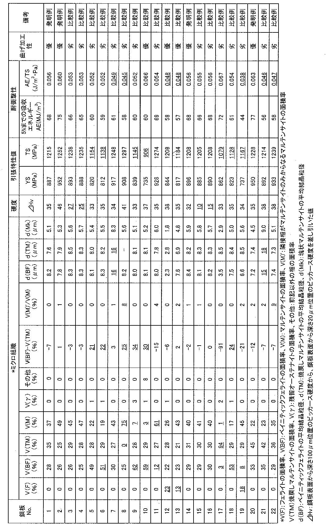
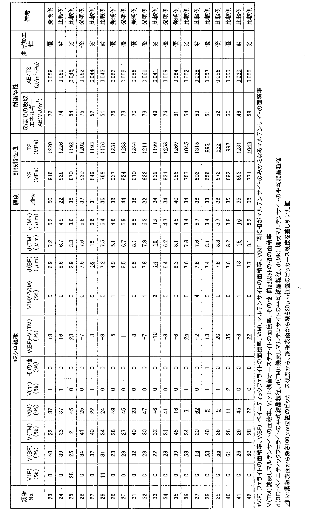
- the obtained hot-dip galvanized steel sheet or alloyed hot-dip galvanized steel sheet is subjected to skin pass rolling with a rolling reduction of 0.3%, and ferrite (F), martensite (M), tempered martensite according to the above-described method.
- the area ratios of (TM), bainitic ferrite (BF) and retained austenite were determined.
- average crystal grain sizes of massive martensite, tempered martensite and bainitic ferrite were determined.
- hardness difference ⁇ Hv hardness difference ⁇ Hv, tensile properties, bending workability and impact energy absorption ability were determined.
- ⁇ Hardness test> A test piece having a width of 10 mm and a length of 15 mm with a cross section in the direction parallel to the rolling direction was taken, and a Vickers hardness test was performed at 20 ⁇ m and 100 ⁇ m positions from the surface. The load is 50 g, 5 points are measured at each plate thickness position, the average value of 3 points Hv excluding the maximum value and the minimum value is obtained as the hardness Hv at that position, and the hardness Hv at 100 ⁇ m position to the hardness at 20 ⁇ m position A value obtained by subtracting Hv was defined as a hardness difference ⁇ Hv.
- ⁇ Tensile test> A JIS No.
- JIS Z2201 tensile test piece 5 tensile test piece (JIS Z2201) was taken in a direction perpendicular to the rolling direction, and subjected to a tensile test in accordance with JIS Z 2241 with a strain rate of 10 ⁇ 3 / s, yield strength (YS). The tensile strength (TS) was determined. YS was 0.2% proof stress. In addition, TS set 1180 MPa or more as the pass.
- ⁇ Bending test> A strip-shaped test piece having a width of 35 mm and a length of 100 mm with the direction parallel to the rolling direction as the bending test axis direction was collected and subjected to a bending test.
- a 90 ° V bending test was performed with a stroke speed of 10 mm / s, an indentation load of 10 ton, a pressing holding time of 5 seconds, and a bending radius R of 1 mm.
- the ridge line part of the bending apex was observed with a 10-fold magnifier, and a case where a crack of 1 mm or more was observed was judged as inferior, and a crack of less than 1 mm was judged as excellent.
- ⁇ Impact tensile test> A test piece having a parallel part width of 5 mm and a length of 7 mm with the direction perpendicular to the rolling direction as the tensile test direction was collected, and the strain rate was 2000 using an impact tensile tester applying the Hopkinson bar method.
- a high-strength hot-dip galvanized steel sheet excellent in impact resistance and bending workability can be obtained, which contributes to the weight reduction of automobiles and has the excellent effect of greatly contributing to higher performance of automobile bodies. Play.
- a high-strength hot-dip galvanized steel sheet having a TS of 1180 MPa or more and excellent impact resistance and bending workability can be obtained.
- the high-strength hot-dip galvanized steel sheet of the present invention when used for automotive parts, it contributes to reducing the weight of an automobile and greatly contributes to improving the performance of an automobile body.
Landscapes
- Chemical & Material Sciences (AREA)
- Engineering & Computer Science (AREA)
- Materials Engineering (AREA)
- Mechanical Engineering (AREA)
- Metallurgy (AREA)
- Organic Chemistry (AREA)
- Thermal Sciences (AREA)
- Physics & Mathematics (AREA)
- Crystallography & Structural Chemistry (AREA)
- Chemical Kinetics & Catalysis (AREA)
- Oil, Petroleum & Natural Gas (AREA)
- Heat Treatment Of Sheet Steel (AREA)
- Coating With Molten Metal (AREA)
Abstract
Description
[1]質量%で、C:0.10%超え~0.18%未満、Si:0.01~1.00%、Mn:1.5~4.0%、P:0.100%以下、S:0.020%以下、Al:0.010~0.500%、Cr:0.010~2.000%、Nb:0.005~0.100%、Ti:0.005~0.100%、B:0.0005%超え~0.0030%以下を含み、残部がFeおよび不可避的不純物からなる成分組成を有し、ミクロ組織が、面積率0~10%のフェライト、面積率15~60%のマルテンサイト、面積率20~50%の焼戻しマルテンサイト、面積率20~50%のベイニティックフェライトからなり、塊状マルテンサイト、焼戻しマルテンサイトおよびベイニティックフェライトの平均結晶粒径がそれぞれ15μm以下、ベイニティックフェライトの面積率から焼戻しマルテンサイトの面積率を差し引いた値が20%以下、全マルテンサイトの面積率に占める隣接相がマルテンサイトのみからなるマルテンサイトの面積率が5%以下、鋼板表面から深さ100μm位置のビッカース硬度から、鋼板表面から深さ20μm位置のビッカース硬度を差し引いた値が30以上である、鋼板の表面に溶融亜鉛めっき皮膜を有することを特徴とする高強度溶融亜鉛めっき鋼板。
[2]さらに、質量%で、Mo:0.005~2.000%、V:0.005~2.000%、Ni:0.005~2.000%、Cu:0.005~2.000%から選ばれる少なくとも一種の元素を含有することを特徴とする[1]に記載の高強度溶融亜鉛めっき鋼板。
[3]さらに、質量%で、Ca:0.001~0.005%、REM:0.001~0.005%から選ばれる少なくとも一種の元素を含有することを特徴とする[1]または[2]に記載の高強度溶融亜鉛めっき鋼板。
[4]前記溶融亜鉛めっき皮膜は合金化溶融亜鉛めっき皮膜であることを特徴とする[1]~[3]のいずれかに記載の高強度溶融亜鉛めっき鋼板。
[5][1]~[3]のいずれかに記載の成分を有するスラブに、最終仕上げパスの圧下率が10%以上で仕上げ圧延温度を850~950℃として熱間圧延を施し、次いで600~700℃での滞留時間が10秒以下となるように冷却した後、450℃以上~600℃未満の巻取温度で巻取り熱延板とし、該熱延板に20%超えの圧下率で冷間圧延して冷延板とし、該冷延板に焼鈍を施すに際し、300℃~焼鈍温度までの温度域において、-45~20℃の露点および0.80以上の空気比で0.5℃/s以上の平均加熱速度で加熱し、焼鈍温度を(Ac3変態点-20)~950℃として10~1000秒の保持時間で保持した後、5℃/s以上の平均冷却速度で冷却停止温度が200℃以上~450℃未満となるように冷却し、前記冷却停止温度で保持時間1秒以上~10秒未満保持した後、450~550℃に再加熱してその温度で10~1000秒保持した後、溶融亜鉛めっき処理を施すことを特徴とする高強度溶融亜鉛めっき鋼板の製造方法。
[6]溶融亜鉛めっき処理後、さらに合金化処理を施すことを特徴とする[5]に記載の高強度溶融亜鉛めっき鋼板の製造方法。
C:0.10%超え~0.18%未満
Cは、マルテンサイトおよび焼戻しマルテンサイトの強度を増大させ、TSを上昇させるために必要な元素である。C量が0.10%以下では、マルテンサイトおよび焼戻しマルテンサイトの強度が低く、TSが1180MPa以上を得ることができない。一方、C量が0.18%以上では耐衝撃性が劣化する。したがって、C量は0.10%超え~0.18%未満とする。好ましくは0.10%超え~0.15%とする。
Siは、鋼を固溶強化してTSを上昇させるのに有効な元素である。こうした効果を得るには、Si量を0.01%以上とする必要がある。一方、1.00%を超えると、めっき性や溶接性の劣化を招く。したがって、Si量は0.01~1.00%とする。好ましくは0.01~0.80%、より好ましくは0.01~0.60%とする。
Mnは、鋼を固溶強化してTSを上昇させる。また、フェライト変態やベイナイト変態を抑制してマルテンサイトを生成させ、TSを上昇させる元素である。こうした効果を得るには、Mn量を1.5%以上にする必要がある。一方、Mn量が4.0%を超えると、介在物の増加が顕著になり、鋼の清浄度や耐衝撃性劣化の原因となる。したがって、Mn量は1.5~4.0%とする。好ましくは1.8~3.5%、より好ましくは2.0~3.0%とする。
Pは、粒界偏析により耐衝撃性を劣化させ、溶接性を劣化させるため、その量は極力低減することが望ましい。しかし、製造コストの面などから、P量は0.100%以下とする。下限は特に規定しない。なお、P量が0.001%未満では生産能率の低下を招くため、0.001%以上が好ましい。
Sは、MnSなどの介在物として存在して、溶接性を劣化させるため、その量は極力低減することが好ましい。しかし、製造コストの面から、S量は0.020%以下とする。下限は特に規定しない。なお、S量が0.0005%未満では生産能率の低下を招くため、0.0005%以上が好ましい。
Alは、脱酸剤として作用し、脱酸工程で添加することが好ましい。こうした効果を得るには、Al量を0.010%以上にする必要がある。一方、Al量が0.500%を超えると、連続鋳造時のスラブ割れの危険性が高まる。したがって、Al量は0.010~0.500%とする。
Crは、フェライト変態やベイナイト変態を抑制してマルテンサイトを生成させ、TSを上昇させる元素である。こうした効果を得るには、Cr量を0.010%以上にする必要がある。一方、Cr量が2.000%を超えると、その効果は飽和しコストアップをまねく。したがって、Cr量は0.010~2.000%とする。好ましくは0.010~1.500%、より好ましくは0.010~1.000%とする。
Nbは、焼鈍時にフェライトの再結晶を抑制し、結晶粒を微細化するのに有効な元素である。こうした効果を得るには、Nb量を0.005%以上にする必要がある。一方、Nb量が0.100%を超えると、その効果は飽和し、コストアップをまねく。したがって、Nb量は0.005~0.100%とする。好ましくは0.010~0.080%、より好ましくは0.010~0.060%とする。
Tiは、焼鈍時にフェライトの再結晶を抑制し、結晶粒を微細化するのに有効な元素である。こうした効果を得るには、Ti量を0.005%以上にする必要がある。一方、Ti量が0.100%を超えると、その効果は飽和し、コストアップをまねく。したがって、Ti量は0.005~0.100%とする。好ましくは0.010~0.080%、より好ましくは0.010~0.060%とする。
Bは、粒界からのフェライトおよびベイナイトの核生成を抑制し、マルテンサイトを得るのに有効な元素である。こうした効果を得るには、B量を0.0005%超えにする必要がある。一方、B量が0.0030%を超えると、その効果が飽和し、コストアップを招く。したがって、B量は0.0005%超え~0.0030%以下とする。好ましくは0.0005%超え~0.0025%以下、より好ましくは0.0005%超え~0.0020%以下とする。
Mo、V、Ni、Cuは、マルテンサイトなどの低温変態相を生成させるため、高強度化に有効な元素である。こうした効果を得るには、Mo、V、Ni、Cuから選ばれる少なくとも1種の元素を含有し、Mo、V、Ni、Cuの含有量はそれぞれ0.005%以上にすることが好ましい。一方、Mo、V、Ni、Cuの含有量がそれぞれ2.000%を超えると、その効果が飽和し、コストアップを招く。したがって、Mo、V、Ni、Cuの含有量はそれぞれ0.005~2.000%とすることが好ましい。
Ca、REMは、いずれも硫化物の形態制御により加工性を改善させるのに有効な元素である。こうした効果を得るには、Ca、REMから選ばれる少なくとも1種の元素を含有し、Ca、REMの含有量はそれぞれ0.001%以上とすることが好ましい。一方、Ca、REMのそれぞれの含有量が0.005%を超えると、鋼の清浄度に悪影響を及ぼし曲げ加工性等の特性が低下するおそれがある。したがって、Ca、REMの含有量はそれぞれ0.001~0.005%とすることが好ましい。
フェライトの面積率:0~10%
フェライトの面積率が10%を超えると、1180MPa以上のTSと耐衝撃性を両立することが困難となる。したがって、フェライトの面積率は10%以下とする。好ましくは5%以下、より好ましくは2%以下とする。なお、本発明におけるフェライトとは、ポリゴナルフェライトである。
マルテンサイトは強度を上昇させる効果があり、1180MPaのTSを得るためには必要である。マルテンサイトの面積率が15%未満では、1180MPa以上のTSを得ることが困難となる。一方、マルテンサイトの面積率が60%を超えると、曲げ加工性が劣化する。したがって、マルテンサイトの面積率は15~60%とする。好ましくは20~55%とする。
焼戻しマルテンサイトは、耐衝撃性および曲げ加工性を向上させるのに有効である。焼戻しマルテンサイトの面積率が20%未満では、こうした効果を十分に得られない。一方、50%を超えると、1180MPa以上のTSを得ることが困難となる。したがって、焼戻しマルテンサイトの面積率は20~50%とする。好ましくは25~45%、より好ましくは25~40%とする。
ベイニティックフェライトは、強度や耐衝撃性を大きく低下させずに鋼の曲げ性を向上させるのに有効である。ベイニティックフェライトの面積率が20%未満では、こうした効果を十分に得られない。一方、50%を超えると、1180MPa以上のTSを得ることが困難となる。したがって、ベイニティックフェライトの面積率は20~50%とする。好ましくは25~45%、より好ましくは25~40%とする。
本発明において、主体組織であるマルテンサイト、焼戻しマルテンサイトおよびベイニティックフェライトについて、いずれも微細であることが重要である。マルテンサイトのうち、塊状マルテンサイト、焼戻しマルテンサイト、およびベイニティックフェライトが微細であることにより、耐衝撃性および曲げ加工性が向上する。塊状マルテンサイト、焼戻しマルテンサイトおよびベイニティックフェライトの平均結晶粒径がそれぞれ15μmを超えると、耐衝撃性および曲げ性が低下する。したがって、塊状マルテンサイト、焼戻しマルテンサイトおよびベイニティックフェライトの平均結晶粒径はそれぞれ15μm以下とする。好ましくはそれぞれ12μm以下、より好ましくはそれぞれ10μm以下とする。なお、本発明における塊状マルテンサイトとは、旧オーステナイト粒界を含むマルテンサイトであり、ベイニティックフェライト中に孤立する島状マルテンサイトは含まない。
ベイニティックフェライトの面積率から焼戻しマルテンサイトの面積率を差し引いた値が20%を超えると、曲げ加工性が劣化する。このメカニズムは明らかではないが、次のように推測される。焼戻しマルテンサイトは、ベイニティックフェライトとマルテンサイトの中間の硬さをもち、ひずみ分配の均一化に寄与していると考えられる。ベイニティックフェライトが多すぎると、焼戻しマルテンサイトの中間層の役割が不十分になり、曲げ加工性が劣化する。ベイニティックフェライトが少なすぎると、延性低下起因で曲げ加工性劣化が生じる。したがって、ベイニティックフェライトの面積率から焼戻しマルテンサイトの面積率を差し引いた値は20%以下とする。なお、この値は0%以下となっても問題はない。
全マルテンサイトの面積率に占める隣接相がマルテンサイトのみからなるマルテンサイトの面積率(全マルテンサイトに対する隣接相がマルテンサイトのみからなるマルテンサイトの面積率)の割合が5%以下
硬質なマルテンサイトが複数隣接し、マルテンサイトが局在化すると加工や衝突等の際、不均一にひずみが導入されるため、曲げ加工性や耐衝撃性の劣化を招く。全マルテンサイトの面積率に占める隣接相がマルテンサイトのみからなるマルテンサイトの面積率の割合が5%を超えると、曲げ加工性や耐衝撃性が顕著に劣化する。したがって、全マルテンサイトの面積率に占める隣接相がマルテンサイトのみからなるマルテンサイトの面積率の割合は5%以下、好ましくは3%以下、より好ましくは2%以下とする。
鋼板表面から100μm位置のビッカース硬度(Hv100)と、鋼板表面から20μm位置のビッカース硬度(Hv20)との差(Hv100-Hv20)であるΔHvが30未満では曲げ加工性が劣化する。このメカニズムは明らかではないが、次のように推測される。曲げ加工の際、亀裂が確認され始めるのは鋼板表面から100μm程度の深さまで亀裂が伸展した時である。したがって、微小亀裂の抑制にあたっては、鋼板の平均の特性に加えて、鋼板表面から100μm以内の特性の制御が重要であると考えられる。曲げ加工の際は鋼板の表面から内部にかけてひずみ勾配が生じる。あらかじめ鋼板表面近傍に逆の強度勾配(ひずみの大きい表層ほど低強度)を与えることで、亀裂の発生および伝播が抑制されるものと考えられる。この強度勾配を、上記ΔHvで表し、ΔHvを30以上とすることで曲げ加工性が向上する。
Cybernetics社製のImage-Proを用いて各相の面積率を求め、3視野の面積率の平均値を各相の面積率とした。前記画像データにおいて、フェライトは黒色、ベイニティックフェライトは島状のマルテンサイトを含む黒色あるいは方位の揃った炭化物を含む灰色、焼戻しマルテンサイトは微細な方位の揃っていない炭化物を含む明灰色、マルテンサイトは白色として区別できる。
本発明の高強度鋼板は、上記の成分組成を有するスラブに、最終仕上げパスの圧下率が10%以上で仕上げ圧延温度を850~950℃として熱間圧延を施し、次いで600~700℃での滞留時間が10秒以下となるように冷却した後、450℃以上~600℃未満の巻取温度で巻取り熱延板とし、該熱延板に20%超えの圧下率で冷間圧延して冷延板とし、該冷延板に焼鈍を施すに際し、300℃~焼鈍温度までの温度域において、-45~20℃の露点および0.80以上の空気比で0.5℃/s以上の平均加熱速度で加熱し、焼鈍温度を(Ac3変態点-20)~950℃として10~1000秒の保持時間で保持した後、5℃/s以上の平均冷却速度で冷却停止温度が200℃以上~450℃未満となるように冷却し、前記冷却停止温度で保持時間1秒以上~10秒未満保持した後、450~550℃に再加熱してその温度で10~1000秒保持した後、溶融亜鉛めっき処理を施すことを特徴とする。
熱間圧延の仕上げ圧延工程において、最終仕上げパスの圧下率が10%未満では、焼鈍後の鋼板表層の硬度差ΔHvが30未満となって曲げ性が劣化する。このメカニズムは明らかではないが、仕上げ圧延の圧下率が低下すると熱延板の表層組織が粗大になり、酸素の拡散経路が減少して表層付近の炭素の希薄化が抑制されるためと推測される。したがって、最終仕上げパスの圧下率は10%以上とする。
最終仕上げパスの仕上げ圧延温度が850℃未満では、焼鈍後の鋼板表層の硬度差ΔHvが30未満となって曲げ性が劣化する。このメカニズムは明らかではないが、仕上げ圧延温度が低下すると鋼板表層に伸展組織が残存するため、酸素の拡散経路が減少して表層付近の炭素の希薄化が抑制されるためと推測される。一方、950℃を超えると結晶粒が粗大化し、本発明のミクロ組織が得られない。したがって、仕上げ圧延温度は850~950℃とする。
仕上げ圧延後の冷却において、600~700℃における滞留時間が10秒を超えると、B炭化物等のBを含む化合物が生成して、鋼中の固溶Bが低下する。その結果、焼鈍時のBの効果が減退して本発明のミクロ組織が得られなくなる。したがって、600~700℃の滞留時間は10秒以下とする。好ましくは、8秒以下とする。
巻取温度が600℃以上では、B炭化物等のBを含む化合物が生成して、鋼中の固溶Bが低下する。その結果、焼鈍時のBの効果が減退して本発明のミクロ組織が得られなくなる。一方、450℃未満では、鋼板表層への酸素の供給が抑制され、表層付近の炭素の希薄化が抑制されて、焼鈍後の鋼板表層の硬度差ΔHvが30未満となり曲げ性が劣化する。したがって、巻取温度は450℃以上~600℃未満とする。好ましくは、500℃以上~600℃未満とする。
圧下率が20%以下では、粗大粒が生成して耐衝撃性を劣化させる。したがって、冷間圧延の圧下率は20%超え、好ましくは30%以上とする。なお、上限は特に規定しないが、形状の安定性等の観点から90%以下程度が好ましい。
300℃~焼鈍温度までの温度域において、炉内雰囲気の露点が-45℃未満では鋼板表層に酸素が十分供給されず、表層付近の炭素の希薄化が抑制されて、焼鈍後の鋼板表層の硬度差ΔHvが30未満となって、曲げ性が劣化する。一方、露点が20℃を超えるとめっき性が劣化する。したがって、300℃~焼鈍温度までの露点は-45~20℃とする。好ましくは-40~0℃、より好ましくは-40~-10℃である。
300℃~焼鈍温度までの温度域において、酸化処理を行う際の空気比が0.80未満では鋼板表層に酸素が十分供給されず表層付近の炭素の希薄化が抑制されて、焼鈍後の鋼板表層の硬度差ΔHvが30未満となって、曲げ性が劣化する。したがって、空気比は0.80以上、好ましくは0.90以上、より好ましくは1.00以上とする。上限は特に規定しないが、1.50を超えると生産性を阻害するため、1.50以下が好ましい。なお、ここで空気比とは、製鉄所の副生ガスであるコークス炉ガス(COG)等の燃料と空気の比の意味である。また、この酸化処理を行う酸化炉の種類は特に限定するものではないが、直火バーナを備えた直火式の加熱炉を使用することが好適である。直火バーナとは、製鉄所の副生ガスであるコークス炉ガス(COG)等の燃料と空気を混ぜて燃焼させたバーナ火炎を直接鋼板表面に当てて鋼板を加熱するものである。直火バーナの燃料としては、COG、液化天然ガス(LNG)等を使用できる。
300℃~焼鈍温度までの温度域において、平均加熱速度が0.5℃/s未満ではオーステナイトの結晶粒が粗大になり、本発明のミクロ組織が得られない。したがって、平均加熱速度は0.5℃/s以上とする。
焼鈍温度が(Ac3変態点-20)℃未満では、オーステナイトの生成が不十分となり、過剰なフェライトが生成して本発明のミクロ組織が得られない。一方、950℃を超えるとオーステナイトの結晶粒が粗大になり、本発明のミクロ組織が得られない。したがって、焼鈍温度は(Ac3変態点-20)~950℃とする。好ましくは(Ac3変態点-10)~900℃、より好ましくはAc3変態点~880℃とする。なお、Ac3変態点は以下の式(1)から求める。
Ac3変態点(℃)=910-203×[C]0.5+44.7×[Si]-30×[Mn]-11×[Cr]・・・(1)
ここで、[C]、[Si]、[Mn]および[Cr]は鋼中の各元素の質量%である。
焼鈍温度である(Ac3変態点-20)~950℃での保持時間が10秒未満では、オーステナイトの生成が不十分となり、過剰なフェライトが生成して本発明のミクロ組織が得られない。一方、1000秒を超えるとオーステナイトの結晶粒が粗大になり、本発明のミクロ組織が得られない。したがって、保持時間は10~1000秒とする。好ましくは30~600秒とする。
平均冷却速度が5℃/s未満では、冷却中にフェライトやベイナイトが過度に生成して本発明のミクロ組織が得られない。したがって、平均冷却速度は5℃/s以上とする。
冷却停止温度が450℃以上では焼戻しマルテンサイトが生じず、本発明のミクロ組織が得られない。一方、200℃未満では焼戻しマルテンサイトが過剰になり、本発明のミクロ組織が得られない。したがって、冷却停止温度は200℃以上~450℃未満とする。好ましくは250~450℃未満、より好ましくは300~430℃とする。
本発明のように焼戻しマルテンサイトが50%以下になるような場合、冷却停止温度200℃以上~450℃未満での保持時間が1秒未満では、焼戻しマルテンサイトの分布が不均一になり、耐衝撃性が劣化する。一方、10秒以上ではベイナイト変態が過度に進行して本発明のミクロ組織が得られない。したがって、保持時間は1秒以上~10秒未満とする。
450℃未満ではベイナイトが過度に生成して本発明のミクロ組織が得られない。一方、550℃を超えるとフェライトが過剰に生成して本発明のミクロ組織が得られない。したがって、450~550℃に再加熱する。
保持時間が10秒未満ではベイナイト変態が不十分になって、本発明のミクロ組織が得られない。一方、1000秒を超えるとベイナイト変態が過度に起きて本発明のミクロ組織が得られない。したがって、保持時間は10~1000秒、好ましくは30~500秒とする。

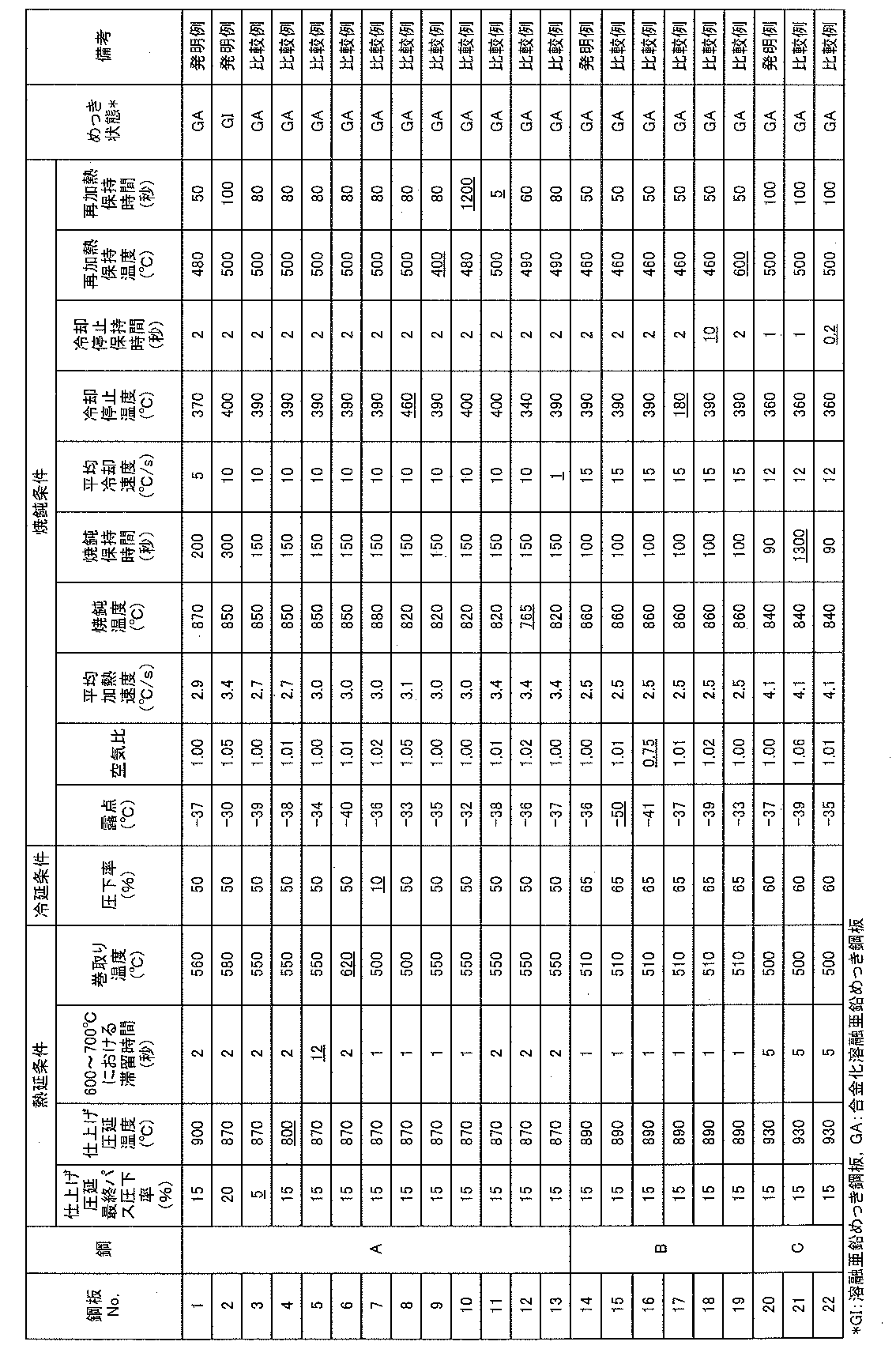
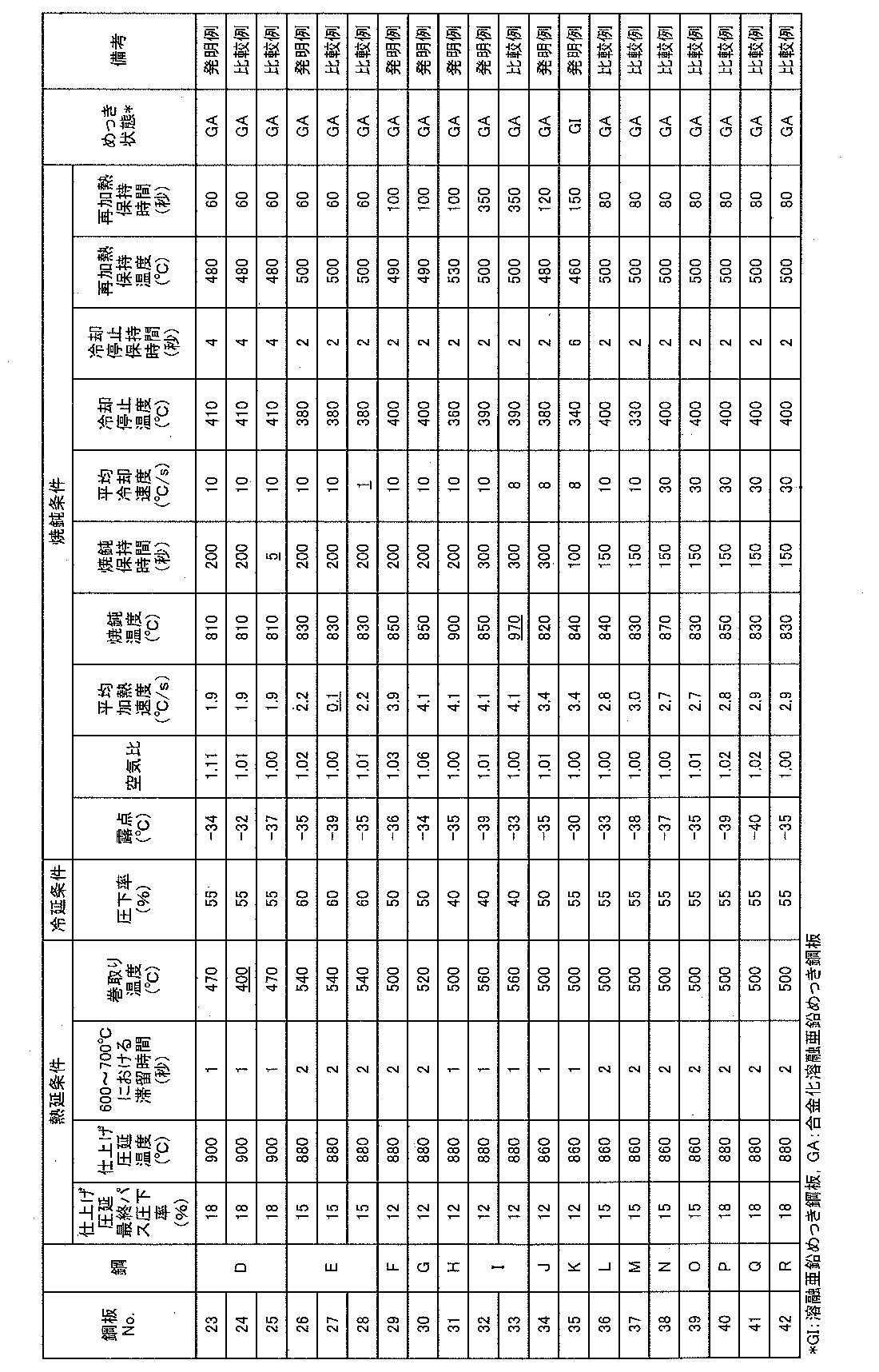
また、以下の試験方法にしたがい、硬度差ΔHv、引張特性、曲げ加工性および衝突エネルギー吸収能を求めた。
圧延方向に対して平行方向を断面とする幅が10mm、長さが15mmの試験片を採取し、表面から深さ20μmおよび100μm位置について、ビッカース硬度試験を行った。荷重は50gとし、各板厚位置で5点測定し、最大値と最小値を除いた3点のHvの平均値を、その位置における硬度Hvとして求め、100μm位置の硬度Hvから20μm位置の硬度Hvを差し引いた値を硬度差ΔHvとした。
<引張試験>
圧延方向に対して直角方向にJIS5号引張試験片(JIS Z2201)を採取し、歪速度が10-3/sとするJIS Z 2241の規定に準拠した引張試験を行い、降伏強さ(YS)および引張強度(TS)を求めた。YSは0.2%耐力とした。なお、TSが1180MPa以上を合格とした。
<曲げ試験>
圧延方向に対して平行方向を曲げ試験軸方向とする、幅が35mm、長さが100mmの短冊形の試験片を採取し、曲げ試験を行った。ストローク速度を10mm/s、押込み荷重を10ton、押付け保持時間を5秒、曲げ半径Rを1mmとして、90°V曲げ試験を行った。曲げ頂点の稜線部を10倍の拡大鏡で観察し、1mm以上の亀裂が認められたものを劣、亀裂が1mm未満のものを優として判定した。
<衝撃引張試験>
圧延方向に対して直角方向を引張試験方向とする、平行部の幅が5mm、長さが7mmの試験片を採取し、ホプキンソン棒法を応用した衝撃引張試験機を用いて、ひずみ速度が2000/sで引張試験を行った。ひずみ量が5%までの吸収エネルギー(AE)を求めて、衝突エネルギー吸収能(耐衝撃性)を評価した(社会法人日本鉄鋼協会「鉄と鋼」vol.83(1997)No.11,p.748-753、参照)。なお、上記吸収エネルギー(AE)は、応力真ひずみ曲線を、ひずみ量が0~5%の範囲を積分することにより求めた。なお、AE/TSが0.050J/m3・Pa以上を合格とした。
Claims (6)
- 質量%で、C:0.10%超え~0.18%未満、Si:0.01~1.00%、Mn:1.5~4.0%、P:0.100%以下、S:0.020%以下、Al:0.010~0.500%、Cr:0.010~2.000%、Nb:0.005~0.100%、Ti:0.005~0.100%、B:0.0005%超え~0.0030%以下を含み、残部がFeおよび不可避的不純物からなる成分組成を有し、
ミクロ組織が、面積率0~10%のフェライト、面積率15~60%のマルテンサイト、面積率20~50%の焼戻しマルテンサイト、面積率20~50%のベイニティックフェライトからなり、
塊状マルテンサイト、焼戻しマルテンサイトおよびベイニティックフェライトの平均結晶粒径がそれぞれ15μm以下、
ベイニティックフェライトの面積率から焼戻しマルテンサイトの面積率を差し引いた値が20%以下、
全マルテンサイトの面積率に占める隣接相がマルテンサイトのみからなるマルテンサイトの面積率が5%以下であり、
鋼板表面から深さ100μm位置のビッカース硬度から、鋼板表面から深さ20μm位置のビッカース硬度を差し引いた値が30以上である、鋼板の表面に溶融亜鉛めっき皮膜を有することを特徴とする高強度溶融亜鉛めっき鋼板。 - さらに、質量%で、Mo:0.005~2.000%、V:0.005~2.000%、Ni:0.005~2.000%、Cu:0.005~2.000%から選ばれる少なくとも一種の元素を含有することを特徴とする請求項1に記載の高強度溶融亜鉛めっき鋼板。
- さらに、質量%で、Ca:0.001~0.005%、REM:0.001~0.005%から選ばれる少なくとも一種の元素を含有することを特徴とする請求項1または2に記載の高強度溶融亜鉛めっき鋼板。
- 前記溶融亜鉛めっき皮膜は合金化溶融亜鉛めっき皮膜であることを特徴とする請求項1~3のいずれかに記載の高強度溶融亜鉛めっき鋼板。
- 請求項1~3のいずれかに記載の成分を有するスラブに、
最終仕上げパスの圧下率が10%以上で仕上げ圧延温度を850~950℃として熱間圧延を施し、
次いで600~700℃での滞留時間が10秒以下となるように冷却した後、
450℃以上~600℃未満の巻取温度で巻取り熱延板とし、
該熱延板に20%超えの圧下率で冷間圧延して冷延板とし、
該冷延板に焼鈍を施すに際し、
300℃~焼鈍温度までの温度域において、-45~20℃の露点および0.80以上の空気比で0.5℃/s以上の平均加熱速度で加熱し、
焼鈍温度を(Ac3変態点-20)~950℃として10~1000秒の保持時間で保持した後、5℃/s以上の平均冷却速度で冷却停止温度が200℃以上~450℃未満となるように冷却し、前記冷却停止温度で保持時間1秒以上~10秒未満保持した後、450~550℃に再加熱してその温度で10~1000秒保持した後、溶融亜鉛めっき処理を施すことを特徴とする高強度溶融亜鉛めっき鋼板の製造方法。 - 溶融亜鉛めっき処理後、さらに合金化処理を施すことを特徴とする請求項5に記載の高強度溶融亜鉛めっき鋼板の製造方法。
Priority Applications (5)
| Application Number | Priority Date | Filing Date | Title |
|---|---|---|---|
| KR1020167018747A KR101828196B1 (ko) | 2013-12-18 | 2014-12-01 | 고강도 용융 아연 도금 강판 및 그 제조 방법 |
| EP14871118.7A EP3085802B1 (en) | 2013-12-18 | 2014-12-01 | High strength hot-dip galvanized steel sheet and manufacturing method therefor |
| MX2016007948A MX380136B (es) | 2013-12-18 | 2014-12-01 | Lámina de acero galvanizada por inmersión en caliente de alta resistencia y método para la producción de la misma. |
| CN201480068976.0A CN105829563B (zh) | 2013-12-18 | 2014-12-01 | 高强度熔融镀锌钢板及其制造方法 |
| US15/106,606 US10227672B2 (en) | 2013-12-18 | 2014-12-01 | High-strength hot-dip galvanized steel sheet and method for producing the same |
Applications Claiming Priority (2)
| Application Number | Priority Date | Filing Date | Title |
|---|---|---|---|
| JP2013-260986 | 2013-12-18 | ||
| JP2013260986A JP5862651B2 (ja) | 2013-12-18 | 2013-12-18 | 耐衝撃性および曲げ加工性に優れた高強度溶融亜鉛めっき鋼板およびその製造方法 |
Publications (1)
| Publication Number | Publication Date |
|---|---|
| WO2015092987A1 true WO2015092987A1 (ja) | 2015-06-25 |
Family
ID=53402366
Family Applications (1)
| Application Number | Title | Priority Date | Filing Date |
|---|---|---|---|
| PCT/JP2014/005982 Ceased WO2015092987A1 (ja) | 2013-12-18 | 2014-12-01 | 高強度溶融亜鉛めっき鋼板およびその製造方法 |
Country Status (7)
| Country | Link |
|---|---|
| US (1) | US10227672B2 (ja) |
| EP (1) | EP3085802B1 (ja) |
| JP (1) | JP5862651B2 (ja) |
| KR (1) | KR101828196B1 (ja) |
| CN (1) | CN105829563B (ja) |
| MX (1) | MX380136B (ja) |
| WO (1) | WO2015092987A1 (ja) |
Cited By (4)
| Publication number | Priority date | Publication date | Assignee | Title |
|---|---|---|---|---|
| WO2017108251A1 (en) | 2015-12-21 | 2017-06-29 | Voestalpine Stahl Gmbh | High strength galvannealed steel sheet and method of producing such steel sheet |
| EP3409807A4 (en) * | 2016-01-27 | 2019-01-16 | JFE Steel Corporation | HIGH-FIXED GALVANIZED STEEL PLATE WITH A HIGH DEFLECTOR RATIO AND METHOD FOR THE PRODUCTION THEREOF |
| EP3418418A4 (en) * | 2016-03-31 | 2019-01-16 | JFE Steel Corporation | THIN STEEL PLATE, PLATED STEEL PLATE, METHOD FOR PRODUCING HOT-ROLLED STEEL PLATE, METHOD FOR PRODUCING COLD-ROLLED SOLID STEEL PLATE, METHOD FOR PRODUCING THIN STEEL PLATE AND METHOD FOR PRODUCING PLATED STEEL PLATE |
| CN116179941A (zh) * | 2022-12-09 | 2023-05-30 | 攀钢集团攀枝花钢铁研究院有限公司 | 一种低成本含硼780MPa级热镀锌双相钢及其制备方法 |
Families Citing this family (38)
| Publication number | Priority date | Publication date | Assignee | Title |
|---|---|---|---|---|
| JP5858032B2 (ja) * | 2013-12-18 | 2016-02-10 | Jfeスチール株式会社 | 高強度鋼板およびその製造方法 |
| US10544477B2 (en) | 2014-07-25 | 2020-01-28 | Jfe Steel Corporation | Method for manufacturing high-strength galvanized steel sheet |
| MX2018001080A (es) * | 2015-07-29 | 2018-05-07 | Jfe Steel Corp | Lamina de acero laminada en frio, lamina de acero recubierta, metodo para la fabricacion de lamina de acero laminada en frio, y metodo para la fabricacion de lamina de acero recubierta. |
| KR101736620B1 (ko) * | 2015-12-15 | 2017-05-17 | 주식회사 포스코 | 화성처리성 및 구멍확장성이 우수한 초고강도 강판 및 이의 제조방법 |
| KR101736619B1 (ko) * | 2015-12-15 | 2017-05-17 | 주식회사 포스코 | 화성처리성 및 굽힘가공성이 우수한 초고강도 강판 및 이의 제조방법 |
| KR101767762B1 (ko) * | 2015-12-22 | 2017-08-14 | 주식회사 포스코 | 굽힘 가공성이 우수한 고강도 냉연강판 및 그 제조방법 |
| KR102170060B1 (ko) * | 2016-01-27 | 2020-10-26 | 제이에프이 스틸 가부시키가이샤 | 고항복비형 고강도 아연 도금 강판 및 그의 제조 방법 |
| WO2017138384A1 (ja) * | 2016-02-10 | 2017-08-17 | Jfeスチール株式会社 | 高強度亜鉛めっき鋼板及びその製造方法 |
| MX2018011878A (es) * | 2016-03-31 | 2019-01-10 | Jfe Steel Corp | Chapa de acero, chapa de acero revestida, metodo de produccion de chapa de acero laminada en caliente, metodo de produccion de chapa de acero dura laminada en frio, metodo de produccion de chapa de acero y metodo de produccion de chapa de acero revestida. |
| US11136636B2 (en) | 2016-03-31 | 2021-10-05 | Jfe Steel Corporation | Steel sheet, plated steel sheet, method of production of hot-rolled steel sheet, method of production of cold-rolled full hard steel sheet, method of production of steel sheet, and method of production of plated steel sheet |
| MX2019001148A (es) | 2016-08-10 | 2019-06-10 | Jfe Steel Corp | Lamina de acero de alta resistencia y metodo para su fabricacion. |
| KR101967959B1 (ko) * | 2016-12-19 | 2019-04-10 | 주식회사 포스코 | 굽힘 가공성이 우수한 초고강도 강판 및 이의 제조방법 |
| WO2018115936A1 (en) | 2016-12-21 | 2018-06-28 | Arcelormittal | Tempered and coated steel sheet having excellent formability and a method of manufacturing the same |
| WO2018115935A1 (en) * | 2016-12-21 | 2018-06-28 | Arcelormittal | Tempered and coated steel sheet having excellent formability and a method of manufacturing the same |
| CN108240943A (zh) * | 2016-12-24 | 2018-07-03 | 青海大学 | 一种用纳米压痕检测冷轧金属薄板法向应变均匀性的方法 |
| US10895002B2 (en) | 2017-01-30 | 2021-01-19 | Nippon Steel Corporation | Steel sheet |
| JP6414246B2 (ja) | 2017-02-15 | 2018-10-31 | Jfeスチール株式会社 | 高強度鋼板およびその製造方法 |
| MX2019009598A (es) * | 2017-02-20 | 2019-10-02 | Nippon Steel Corp | Lamina de acero de alta resistencia. |
| US11408046B2 (en) | 2017-02-20 | 2022-08-09 | Nippon Steel Corporation | High strength steel sheet |
| CN111936650B (zh) | 2018-03-30 | 2022-04-08 | 杰富意钢铁株式会社 | 高强度镀锌钢板、高强度部件和它们的制造方法 |
| WO2020090302A1 (ja) * | 2018-10-31 | 2020-05-07 | Jfeスチール株式会社 | 高強度部材、高強度部材の製造方法及び高強度部材用鋼板の製造方法 |
| SE542893C2 (en) * | 2018-11-30 | 2020-08-18 | Voestalpine Stahl Gmbh | A resistance spot welded joint comprising a zinc coated ahss steel sheet |
| KR102165223B1 (ko) | 2018-12-19 | 2020-10-13 | 주식회사 포스코 | 열간성형 후 충격특성이 우수한 열간성형용 도금강판, 열간성형 부재 및 이들의 제조방법 |
| KR102658163B1 (ko) * | 2019-03-22 | 2024-04-19 | 닛폰세이테츠 가부시키가이샤 | 고강도 강판 및 그 제조 방법 |
| WO2020196060A1 (ja) | 2019-03-28 | 2020-10-01 | 日本製鉄株式会社 | 高強度鋼板 |
| EP3992315B1 (en) | 2019-06-28 | 2025-01-15 | Nippon Steel Corporation | Steel sheet |
| MX2022006955A (es) * | 2019-12-19 | 2022-07-12 | Nippon Steel Corp | Lamina de acero y metodo de fabricacion de la misma. |
| KR102838553B1 (ko) | 2019-12-20 | 2025-07-28 | 주식회사 포스코 | 표면품질과 전기저항 점 용접성이 우수한 고강도 용융아연도금 강판 및 그 제조방법 |
| JP7095804B2 (ja) | 2020-02-21 | 2022-07-05 | Jfeスチール株式会社 | 高強度溶融亜鉛めっき鋼板の製造方法 |
| WO2021176249A1 (en) * | 2020-03-02 | 2021-09-10 | Arcelormittal | High strength cold rolled and galvannealed steel sheet and manufacturing process thereof |
| EP4123045A4 (en) | 2020-03-16 | 2023-04-26 | Nippon Steel Corporation | Steel plate |
| KR102461164B1 (ko) * | 2020-12-16 | 2022-11-02 | 주식회사 포스코 | 항복강도 및 굽힘특성이 우수한 초고강도 냉연강판 및 그 제조방법 |
| TWI768666B (zh) * | 2021-01-20 | 2022-06-21 | 中國鋼鐵股份有限公司 | 高成形性冷軋鋼材及其製造方法 |
| WO2022254847A1 (ja) * | 2021-05-31 | 2022-12-08 | 日本製鉄株式会社 | 鋼板 |
| KR102606996B1 (ko) | 2021-11-25 | 2023-11-29 | 현대제철 주식회사 | 굽힘 가공성이 우수한 고강도 강판 및 그 제조방법 |
| WO2024105429A1 (en) * | 2022-11-14 | 2024-05-23 | Arcelormittal | High toughness press-hardened steel part and method of manufacturing the same |
| CN117187709A (zh) * | 2023-09-11 | 2023-12-08 | 湖南华菱涟源钢铁有限公司 | 一种不同屈服强度的590MPa级热镀锌双相钢及其制备方法 |
| JP7685099B1 (ja) * | 2024-07-05 | 2025-05-28 | Agc株式会社 | 複合金属シアン化物錯体触媒及びポリエーテル化合物の製造方法 |
Citations (7)
| Publication number | Priority date | Publication date | Assignee | Title |
|---|---|---|---|---|
| JP2010070843A (ja) | 2008-08-19 | 2010-04-02 | Jfe Steel Corp | 加工性に優れた高強度溶融亜鉛めっき鋼板およびその製造方法 |
| JP2011132602A (ja) | 2009-11-30 | 2011-07-07 | Nippon Steel Corp | 高強度冷延鋼板、高強度溶融亜鉛めっき鋼板および高強度合金化溶融亜鉛めっき鋼板 |
| JP2012031462A (ja) | 2010-07-29 | 2012-02-16 | Jfe Steel Corp | 成形性および耐衝撃性に優れた高強度溶融亜鉛めっき鋼板およびその製造方法 |
| JP2012229466A (ja) * | 2011-04-26 | 2012-11-22 | Jfe Steel Corp | 成形性及び形状凍結性に優れた高強度溶融亜鉛めっき鋼板、並びにその製造方法 |
| JP2013216946A (ja) * | 2012-04-10 | 2013-10-24 | Nippon Steel & Sumitomo Metal Corp | 鋼板の製造方法 |
| JP5327140B2 (ja) * | 2010-06-01 | 2013-10-30 | 新日鐵住金株式会社 | 熱間圧延鋼板の冷却方法 |
| JP2013227654A (ja) * | 2012-03-29 | 2013-11-07 | Kobe Steel Ltd | 成形性および形状凍結性に優れた、高強度冷延鋼板、高強度溶融亜鉛めっき鋼板および高強度合金化溶融亜鉛めっき鋼板、ならびにそれらの製造方法 |
Family Cites Families (1)
| Publication number | Priority date | Publication date | Assignee | Title |
|---|---|---|---|---|
| WO2013051238A1 (ja) * | 2011-10-04 | 2013-04-11 | Jfeスチール株式会社 | 高強度鋼板およびその製造方法 |
-
2013
- 2013-12-18 JP JP2013260986A patent/JP5862651B2/ja active Active
-
2014
- 2014-12-01 US US15/106,606 patent/US10227672B2/en active Active
- 2014-12-01 EP EP14871118.7A patent/EP3085802B1/en active Active
- 2014-12-01 CN CN201480068976.0A patent/CN105829563B/zh active Active
- 2014-12-01 KR KR1020167018747A patent/KR101828196B1/ko active Active
- 2014-12-01 MX MX2016007948A patent/MX380136B/es unknown
- 2014-12-01 WO PCT/JP2014/005982 patent/WO2015092987A1/ja not_active Ceased
Patent Citations (7)
| Publication number | Priority date | Publication date | Assignee | Title |
|---|---|---|---|---|
| JP2010070843A (ja) | 2008-08-19 | 2010-04-02 | Jfe Steel Corp | 加工性に優れた高強度溶融亜鉛めっき鋼板およびその製造方法 |
| JP2011132602A (ja) | 2009-11-30 | 2011-07-07 | Nippon Steel Corp | 高強度冷延鋼板、高強度溶融亜鉛めっき鋼板および高強度合金化溶融亜鉛めっき鋼板 |
| JP5327140B2 (ja) * | 2010-06-01 | 2013-10-30 | 新日鐵住金株式会社 | 熱間圧延鋼板の冷却方法 |
| JP2012031462A (ja) | 2010-07-29 | 2012-02-16 | Jfe Steel Corp | 成形性および耐衝撃性に優れた高強度溶融亜鉛めっき鋼板およびその製造方法 |
| JP2012229466A (ja) * | 2011-04-26 | 2012-11-22 | Jfe Steel Corp | 成形性及び形状凍結性に優れた高強度溶融亜鉛めっき鋼板、並びにその製造方法 |
| JP2013227654A (ja) * | 2012-03-29 | 2013-11-07 | Kobe Steel Ltd | 成形性および形状凍結性に優れた、高強度冷延鋼板、高強度溶融亜鉛めっき鋼板および高強度合金化溶融亜鉛めっき鋼板、ならびにそれらの製造方法 |
| JP2013216946A (ja) * | 2012-04-10 | 2013-10-24 | Nippon Steel & Sumitomo Metal Corp | 鋼板の製造方法 |
Non-Patent Citations (1)
| Title |
|---|
| TETSU TO HAGANE, vol. 83, no. 11, 1997, pages 748 - 753 |
Cited By (6)
| Publication number | Priority date | Publication date | Assignee | Title |
|---|---|---|---|---|
| WO2017108251A1 (en) | 2015-12-21 | 2017-06-29 | Voestalpine Stahl Gmbh | High strength galvannealed steel sheet and method of producing such steel sheet |
| US11236414B2 (en) | 2015-12-21 | 2022-02-01 | Voestalpine Stahl Gmbh | High strength galvannealed steel sheet and method of producing such steel sheet |
| EP3409807A4 (en) * | 2016-01-27 | 2019-01-16 | JFE Steel Corporation | HIGH-FIXED GALVANIZED STEEL PLATE WITH A HIGH DEFLECTOR RATIO AND METHOD FOR THE PRODUCTION THEREOF |
| EP3418418A4 (en) * | 2016-03-31 | 2019-01-16 | JFE Steel Corporation | THIN STEEL PLATE, PLATED STEEL PLATE, METHOD FOR PRODUCING HOT-ROLLED STEEL PLATE, METHOD FOR PRODUCING COLD-ROLLED SOLID STEEL PLATE, METHOD FOR PRODUCING THIN STEEL PLATE AND METHOD FOR PRODUCING PLATED STEEL PLATE |
| US11230744B2 (en) | 2016-03-31 | 2022-01-25 | Jfe Steel Corporation | Steel sheet, plated steel sheet, method for producing hot-rolled steel sheet, method for producing cold-rolled full hard steel sheet, method for producing steel sheet, and method for producing plated steel sheet |
| CN116179941A (zh) * | 2022-12-09 | 2023-05-30 | 攀钢集团攀枝花钢铁研究院有限公司 | 一种低成本含硼780MPa级热镀锌双相钢及其制备方法 |
Also Published As
| Publication number | Publication date |
|---|---|
| KR101828196B1 (ko) | 2018-02-09 |
| US10227672B2 (en) | 2019-03-12 |
| EP3085802B1 (en) | 2019-02-13 |
| JP2015117403A (ja) | 2015-06-25 |
| MX380136B (es) | 2025-03-12 |
| EP3085802A1 (en) | 2016-10-26 |
| MX2016007948A (es) | 2016-09-09 |
| CN105829563A (zh) | 2016-08-03 |
| CN105829563B (zh) | 2017-12-19 |
| US20170037488A1 (en) | 2017-02-09 |
| KR20160098373A (ko) | 2016-08-18 |
| JP5862651B2 (ja) | 2016-02-16 |
| EP3085802A4 (en) | 2016-12-28 |
Similar Documents
| Publication | Publication Date | Title |
|---|---|---|
| JP5862651B2 (ja) | 耐衝撃性および曲げ加工性に優れた高強度溶融亜鉛めっき鋼板およびその製造方法 | |
| JP6179461B2 (ja) | 高強度鋼板の製造方法 | |
| JP5858199B2 (ja) | 高強度溶融亜鉛めっき鋼板及びその製造方法 | |
| US11098392B2 (en) | Hot rolled steel sheet for cold rolled steel sheet, hot rolled steel sheet for galvanized steel sheet, and method for producing the same | |
| CA2762935C (en) | High-strength galvannealed steel sheet having excellent formability and fatigue resistance and method for manufacturing the same | |
| EP2881481B1 (en) | High-strength hot-dip galvanized steel sheet having excellent moldability and shape fixability, and method for manufacturing same | |
| US10526679B2 (en) | Method for manufacturing a hot dip galvanized and galvannealed steel sheet having excellent elongation properties | |
| US9598755B2 (en) | High strength galvanized steel sheet having excellent deep drawability and stretch flangeability and method for manufacturing the same | |
| WO2016031165A1 (ja) | 伸びフランジ性、伸びフランジ性の面内安定性および曲げ性に優れた高強度溶融亜鉛めっき鋼板ならびにその製造方法 | |
| JP6079726B2 (ja) | 高強度鋼板の製造方法 | |
| WO2019159771A1 (ja) | 高強度鋼板およびその製造方法 | |
| WO2003078668A1 (fr) | Procede pour fabriquer une feuille d'acier galvanisee a chaud de haute resistance, presentant une excellente ductilite et une grande resistance a la fatigue | |
| WO2011090180A1 (ja) | 材質安定性と加工性に優れた高強度溶融亜鉛めっき鋼板およびその製造方法 | |
| WO2017168957A1 (ja) | 薄鋼板およびめっき鋼板、並びに、熱延鋼板の製造方法、冷延フルハード鋼板の製造方法、薄鋼板の製造方法およびめっき鋼板の製造方法 | |
| WO2016113781A1 (ja) | 高強度鋼板およびその製造方法 | |
| US20230349020A1 (en) | Steel sheet, member, and methods for manufacturing the same | |
| CN107208207B (zh) | 高强度钢板及其制造方法 | |
| WO2015198582A1 (ja) | 高強度鋼板 | |
| US20240247349A1 (en) | High strength cold rolled steel sheet having excellent surface quality and low mechanical property deviation and manufacturing method of same | |
| WO2016147550A1 (ja) | 高強度冷延鋼板およびその製造方法 | |
| US20240384366A1 (en) | High-strength cold-rolled steel sheet having excellent surface quality and low material variation, and method for manufacturing same |
Legal Events
| Date | Code | Title | Description |
|---|---|---|---|
| 121 | Ep: the epo has been informed by wipo that ep was designated in this application |
Ref document number: 14871118 Country of ref document: EP Kind code of ref document: A1 |
|
| WWE | Wipo information: entry into national phase |
Ref document number: MX/A/2016/007948 Country of ref document: MX |
|
| NENP | Non-entry into the national phase |
Ref country code: DE |
|
| WWE | Wipo information: entry into national phase |
Ref document number: 15106606 Country of ref document: US |
|
| ENP | Entry into the national phase |
Ref document number: 20167018747 Country of ref document: KR Kind code of ref document: A |
|
| WWE | Wipo information: entry into national phase |
Ref document number: IDP00201604598 Country of ref document: ID |
|
| REEP | Request for entry into the european phase |
Ref document number: 2014871118 Country of ref document: EP |
|
| WWE | Wipo information: entry into national phase |
Ref document number: 2014871118 Country of ref document: EP |