WO2015087545A1 - Systems and methods for multi-connectivity operation - Google Patents
Systems and methods for multi-connectivity operation Download PDFInfo
- Publication number
- WO2015087545A1 WO2015087545A1 PCT/JP2014/006149 JP2014006149W WO2015087545A1 WO 2015087545 A1 WO2015087545 A1 WO 2015087545A1 JP 2014006149 W JP2014006149 W JP 2014006149W WO 2015087545 A1 WO2015087545 A1 WO 2015087545A1
- Authority
- WO
- WIPO (PCT)
- Prior art keywords
- scg
- enb
- mac
- rrc
- rrc connection
- Prior art date
Links
- 238000000034 method Methods 0.000 title claims abstract description 170
- 238000004891 communication Methods 0.000 claims description 33
- 230000005540 biological transmission Effects 0.000 description 63
- 238000010586 diagram Methods 0.000 description 28
- 230000004044 response Effects 0.000 description 22
- 230000004048 modification Effects 0.000 description 20
- 238000012986 modification Methods 0.000 description 20
- 230000006870 function Effects 0.000 description 19
- 230000002776 aggregation Effects 0.000 description 16
- 238000004220 aggregation Methods 0.000 description 16
- 230000011664 signaling Effects 0.000 description 13
- 239000000872 buffer Substances 0.000 description 10
- 238000005259 measurement Methods 0.000 description 6
- 238000012545 processing Methods 0.000 description 6
- 230000009471 action Effects 0.000 description 5
- 230000008859 change Effects 0.000 description 5
- 230000000977 initiatory effect Effects 0.000 description 5
- 230000001960 triggered effect Effects 0.000 description 5
- 230000003466 anti-cipated effect Effects 0.000 description 4
- 238000013507 mapping Methods 0.000 description 4
- 238000001514 detection method Methods 0.000 description 3
- 230000009977 dual effect Effects 0.000 description 3
- CIWBSHSKHKDKBQ-JLAZNSOCSA-N Ascorbic acid Chemical compound OC[C@H](O)[C@H]1OC(=O)C(O)=C1O CIWBSHSKHKDKBQ-JLAZNSOCSA-N 0.000 description 2
- 230000004913 activation Effects 0.000 description 2
- 230000009286 beneficial effect Effects 0.000 description 2
- 230000008901 benefit Effects 0.000 description 2
- 230000006835 compression Effects 0.000 description 2
- 238000007906 compression Methods 0.000 description 2
- 230000001276 controlling effect Effects 0.000 description 2
- 238000012937 correction Methods 0.000 description 2
- 230000001419 dependent effect Effects 0.000 description 2
- 238000012544 monitoring process Methods 0.000 description 2
- 230000003287 optical effect Effects 0.000 description 2
- 229920000915 polyvinyl chloride Polymers 0.000 description 2
- 238000004873 anchoring Methods 0.000 description 1
- 230000003139 buffering effect Effects 0.000 description 1
- 230000001413 cellular effect Effects 0.000 description 1
- 238000012790 confirmation Methods 0.000 description 1
- 230000009849 deactivation Effects 0.000 description 1
- 230000006872 improvement Effects 0.000 description 1
- 230000007774 longterm Effects 0.000 description 1
- 238000012423 maintenance Methods 0.000 description 1
- 238000005457 optimization Methods 0.000 description 1
- 230000008569 process Effects 0.000 description 1
- 230000007420 reactivation Effects 0.000 description 1
- 230000001105 regulatory effect Effects 0.000 description 1
- 238000000926 separation method Methods 0.000 description 1
- 230000002123 temporal effect Effects 0.000 description 1
- 238000009482 thermal adhesion granulation Methods 0.000 description 1
Images


Classifications
-
- H—ELECTRICITY
- H04—ELECTRIC COMMUNICATION TECHNIQUE
- H04W—WIRELESS COMMUNICATION NETWORKS
- H04W76/00—Connection management
- H04W76/10—Connection setup
- H04W76/15—Setup of multiple wireless link connections
-
- H—ELECTRICITY
- H04—ELECTRIC COMMUNICATION TECHNIQUE
- H04W—WIRELESS COMMUNICATION NETWORKS
- H04W76/00—Connection management
- H04W76/20—Manipulation of established connections
- H04W76/27—Transitions between radio resource control [RRC] states
-
- H—ELECTRICITY
- H04—ELECTRIC COMMUNICATION TECHNIQUE
- H04W—WIRELESS COMMUNICATION NETWORKS
- H04W36/00—Hand-off or reselection arrangements
- H04W36/0005—Control or signalling for completing the hand-off
- H04W36/0055—Transmission or use of information for re-establishing the radio link
- H04W36/0072—Transmission or use of information for re-establishing the radio link of resource information of target access point
-
- H—ELECTRICITY
- H04—ELECTRIC COMMUNICATION TECHNIQUE
- H04W—WIRELESS COMMUNICATION NETWORKS
- H04W36/00—Hand-off or reselection arrangements
- H04W36/24—Reselection being triggered by specific parameters
- H04W36/249—Reselection being triggered by specific parameters according to timing information
-
- H—ELECTRICITY
- H04—ELECTRIC COMMUNICATION TECHNIQUE
- H04W—WIRELESS COMMUNICATION NETWORKS
- H04W76/00—Connection management
- H04W76/10—Connection setup
- H04W76/11—Allocation or use of connection identifiers
-
- H—ELECTRICITY
- H04—ELECTRIC COMMUNICATION TECHNIQUE
- H04W—WIRELESS COMMUNICATION NETWORKS
- H04W36/00—Hand-off or reselection arrangements
- H04W36/0005—Control or signalling for completing the hand-off
- H04W36/0055—Transmission or use of information for re-establishing the radio link
- H04W36/0069—Transmission or use of information for re-establishing the radio link in case of dual connectivity, e.g. decoupled uplink/downlink
- H04W36/00692—Transmission or use of information for re-establishing the radio link in case of dual connectivity, e.g. decoupled uplink/downlink using simultaneous multiple data streams, e.g. cooperative multipoint [CoMP], carrier aggregation [CA] or multiple input multiple output [MIMO]
-
- H—ELECTRICITY
- H04—ELECTRIC COMMUNICATION TECHNIQUE
- H04W—WIRELESS COMMUNICATION NETWORKS
- H04W72/00—Local resource management
-
- H—ELECTRICITY
- H04—ELECTRIC COMMUNICATION TECHNIQUE
- H04W—WIRELESS COMMUNICATION NETWORKS
- H04W76/00—Connection management
- H04W76/10—Connection setup
- H04W76/19—Connection re-establishment
-
- H—ELECTRICITY
- H04—ELECTRIC COMMUNICATION TECHNIQUE
- H04W—WIRELESS COMMUNICATION NETWORKS
- H04W76/00—Connection management
- H04W76/20—Manipulation of established connections
Definitions
- the present disclosure relates generally to communication systems. More specifically, the present disclosure relates to systems and methods for multi-connectivity operation.
- a wireless communication system may provide communication for a number of wireless communication devices, each of which may be serviced by a base station.
- a base station may be a device that communicates with wireless communication devices.
- wireless communication devices may communicate with one or more devices using multiple connections.
- the multiple connections may only offer limited flexibility and efficiency.
- systems and methods that improve communication flexibility and efficiency may be beneficial.
- An aspect of the invention provides a method for receiving a radio resource control (RRC) message by a user equipment (UE), comprising: receiving an RRC connection reconfiguration message including mobility control information; resetting a MAC entity of a master cell group (MCG); and releasing a medium access control (MAC) entity of a secondary cell group (SCG) if any MAC entity of the SCG is established.
- RRC radio resource control
- MCG master cell group
- SCG secondary cell group
- a user equipment for receiving a radio resource control (RRC) message, comprising: a processor; and memory in electronic communication with the processor, wherein instructions stored in the memory are executable to: receive an RRC connection reconfiguration message including mobility control information; reset a MAC entity of a master cell group (MCG); and release a medium access control (MAC) entity of a secondary cell group (SCG) if any MAC entity of the SCG is established.
- RRC radio resource control
- RRC radio resource control
- UE user equipment
- RRC connection reconfiguration message including mobility control information
- MCG master cell group
- MAC medium access control
- SCG secondary cell group
- Another aspect of the invention provides a method for sending a radio resource control (RRC) message by an evolved Node B (eNB), comprising: sending an RRC connection reconfiguration message including mobility control information; wherein the RRC connection reconfiguration message causes a user equipment (UE) resetting a MAC entity of a master cell group (MCG) and releasing a medium access control (MAC) entity of a secondary cell group (SCG) if any MAC entity of the SCG is established.
- RRC radio resource control
- eNB evolved Node B
- a evolved Node B for sending a radio resource control (RRC) message
- RRC radio resource control
- eNB for sending a radio resource control (RRC) message
- RRC radio resource control
- MCG master cell group
- MAC medium access control
- SCG secondary cell group
- Figure 1 is a block diagram illustrating one configuration of one or more evolved Node Bs (eNBs) and one or more user equipments (UEs) in which systems and methods for multi-connectivity operation may be implemented.
- Figure 2 is a flow diagram illustrating one implementation of a method for receiving a radio resource control (RRC) message by a UE.
- Figure 3 is a flow diagram illustrating one implementation of a method for receiving an RRC message by a UE.
- Figure 4 is a flow diagram illustrating one implementation of a method for sending an RRC message by an eNB.
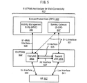
- Figure 5 is a block diagram illustrating configurations of Evolved Universal Terrestrial Radio Access Network (E-UTRAN) architecture in which systems and methods for multi-connectivity operation may be implemented.
- E-UTRAN Evolved Universal Terrestrial Radio Access Network
- Figure 6 is a block diagram illustrating one configuration of an E-UTRAN and a UE in which systems and methods for multi-connectivity operation may be implemented.
- Figure 7 is a thread diagram illustrating one configuration of an RRC connection reconfiguration procedure.
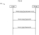
- Figure 8 is a thread diagram illustrating one configuration of a non-contention based random access procedure.
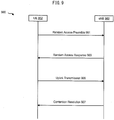
- Figure 9 is a thread diagram illustrating one configuration of a contention-based random access procedure.
- Figure 10 is a block diagram illustrating a first user plane (UP) architecture and a second UP architecture.
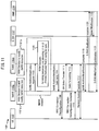
- Figure 11 is a thread diagram illustrating one configuration of secondary evolved Node B (SeNB) addition and modification.
- Figure 12 illustrates various components that may be utilized in a UE.
- UP user plane
- SeNB secondary evolved Node B
- Figure 13 illustrates various components that may be utilized in an eNB
- Figure 14 is a block diagram illustrating one configuration of a UE in which systems and methods for sending feedback information may be implemented.
- Figure 15 is a block diagram illustrating one configuration of an eNB in which systems and methods for receiving feedback information may be implemented.
- a method for receiving an RRC message by a UE includes receiving an RRC connection reconfiguration message including mobility control information.
- a medium access control (MAC) entity of a secondary cell group (SCG) is released if any MAC entity of the SCG is established.
- a MAC entity of a master cell group (MCG) is reset.
- the method may also include re-establishing radio link control (RLC) entities for all radio bearers (RBs) that are established for the MCG.
- RLC entities for all RBs that are established for the SCG may be released, if any RLC entity of the SCG is established.
- the method may also include re-establishing packet data convergence protocol (PDCP) entities for all RBs that are established for the MCG.
- PDCP entities for all RBs that are established for the SCG may be released, if any PDCP entity of the SCG is established.
- a UE for receiving an RRC message includes a processor and memory in electronic communication with the processor. Instructions stored in the memory are executable to receive an RRC connection reconfiguration message including mobility control information. In response to receiving the RRC connection reconfiguration message including mobility control information a MAC entity of a SCG is released if any MAC entity of the SCG is established. In response to receiving the RRC connection reconfiguration message including mobility control information, a MAC entity of a MCG is reset.
- a non-transitory, tangible computer-readable medium for receiving RRC message by a UE includes executable instructions for receiving an RRC connection reconfiguration message including mobility control information.
- the computer-readable medium includes executable instructions for receiving an RRC connection reconfiguration message including mobility control information.
- a MAC entity of a SCG is released if any MAC entity of the SCG is established.
- a MAC entity of a MCG is reset.
- the method includes receiving an RRC connection reconfiguration message including SCG configuration parameters for SCG addition.
- the method also includes ordering, by an RRC of the UE, a MAC of the SCG of the UE to initiate a random access procedure.
- the random access procedure may include a contention resolution. If the random access procedure was initiated by the RRC order and a physical downlink control channel (PDCCH) transmission is addressed to a cell-radio network temporary identifier (C-RNTI) of the SCG of the UE, then the contention resolution may be considered successful. The random access procedure may also be considered successfully completed.
- PDCCH physical downlink control channel
- C-RNTI cell-radio network temporary identifier
- a method for sending an RRC message by an evolved Node B (eNB) includes sending an RRC connection reconfiguration message including SCG configuration parameters for SCG addition to a UE.
- the method also includes controlling a random access procedure initiated by the UE.
- the method may also include sending PDCCH transmission that is addressed to a C-RNTI of the SCG of the UE.
- the PDCCH transmission may cause the UE to consider a random access procedure successfully completed.
- the method may further include considering the random access procedure concerning the SCG addition for the UE successfully completed.
- a UE for receiving an RRC message includes a processor and memory in electronic communication with the processor. Instructions stored in the memory are executable to receive an RRC connection reconfiguration message including SCG configuration parameters for SCG addition. In response to receiving the RRC connection reconfiguration message including SCG configuration parameters for SCG addition, the instructions are further executable to order, by an RRC of the UE, a MAC of the SCG of the UE to initiate a random access procedure.
- the eNB includes a processor and memory in electronic communication with the processor. Instructions stored in the memory are executable to send an RRC connection reconfiguration message including SCG configuration parameters for SCG addition to a UE. The instructions are also executable to control a random access procedure initiated by the UE.
- a non-transitory, tangible computer-readable medium for receiving an RRC message by a UE includes executable instructions for receiving an RRC connection reconfiguration message including SCG configuration parameters for SCG addition.
- the instructions are further executable for ordering, by an RRC of the UE, a MAC of the SCG of the UE to initiate a random access procedure.
- a non-transitory, tangible computer-readable medium for sending an RRC message by an eNB includes executable instructions for sending an RRC connection reconfiguration message including SCG configuration parameters for SCG addition to a UE.
- the instructions are also executable for controlling a random access procedure initiated by the UE.
- 3GPP Long Term Evolution is the name given to a project to improve the Universal Mobile Telecommunications System (UMTS) mobile phone or device standard to cope with future requirements.
- UMTS has been modified to provide support and specification for the Evolved Universal Terrestrial Radio Access (E-UTRA) and Evolved Universal Terrestrial Radio Access Network (E-UTRAN).
- E-UTRA Evolved Universal Terrestrial Radio Access
- E-UTRAN Evolved Universal Terrestrial Radio Access Network
- At least some aspects of the systems and methods disclosed herein may be described in relation to the 3GPP LTE, LTE-Advanced (LTE-A) and other standards (e.g., 3GPP Releases 8, 9, 10, 11 and/or 12). However, the scope of the present disclosure should not be limited in this regard. At least some aspects of the systems and methods disclosed herein may be utilized in other types of wireless communication systems.
- LTE LTE-Advanced
- other standards e.g., 3GPP Releases 8, 9, 10, 11 and/or 12
- a wireless communication device may be an electronic device used to communicate voice and/or data to a base station, which in turn may communicate with a network of devices (e.g., public switched telephone network (PSTN), the Internet, etc.).
- a wireless communication device may alternatively be referred to as a mobile station, a UE, an access terminal, a subscriber station, a mobile terminal, a remote station, a user terminal, a terminal, a subscriber unit, a mobile device, etc.
- Examples of wireless communication devices include cellular phones, smart phones, personal digital assistants (PDAs), laptop computers, netbooks, e-readers, wireless modems, etc.
- PDAs personal digital assistants
- a wireless communication device is typically referred to as a UE.
- the terms "UE” and “wireless communication device” may be used interchangeably herein to mean the more general term "wireless communication device.”
- a base station In 3GPP specifications, a base station is typically referred to as a Node B, an eNB, a home enhanced or evolved Node B (HeNB) or some other similar terminology.
- the terms “base station,” “Node B,” “eNB,” and “HeNB” may be used interchangeably herein to mean the more general term “base station.”
- a “base station” is an access point.
- An access point may be an electronic device that provides access to a network (e.g., Local Area Network (LAN), the Internet, etc.) for wireless communication devices.
- the term “communication device” may be used to denote both a wireless communication device and/or a base station.
- a "cell” may be any communication channel that is specified by standardization or regulatory bodies to be used for International Mobile Telecommunications-Advanced (IMT-Advanced) and all of it or a subset of it may be adopted by 3GPP as licensed bands (e.g., frequency bands) to be used for communication between an eNB and a UE. It should also be noted that in E-UTRA, E-UTRAN overall description, a "cell” is defined as a "combination of downlink and optionally uplink resources.” The linking between the carrier frequency of the downlink resources and the carrier frequency of the uplink resources may be indicated in system information transmitted on the downlink resources.
- Configured cells are those cells of which the UE is aware and is allowed by an eNB to transmit or receive information.
- Configured cell(s) may be serving cell(s). The UE may receive system information and perform the required measurements on all configured cells.
- Configured cell(s)” for a radio connection may consist of a primary cell and/or no, one, or more secondary cell(s).
- Activated cells are those configured cells on which the UE is transmitting and receiving. That is, activated cells are those cells for which the UE monitors the physical downlink control channel (PDCCH) and in the case of a downlink transmission, those cells for which the UE decodes a physical downlink shared channel (PDSCH).
- PDCCH physical downlink control channel
- PDSCH physical downlink shared channel
- Deactivated cells are those configured cells that the UE is not monitoring the transmission PDCCH. It should be noted that a “cell” may be described in terms of differing dimensions. For example, a “cell” may have temporal, spatial (e.g., geographical) and frequency characteristics.
- E-UTRAN evolved universal terrestrial radio access network
- multi-connectivity operation between a user equipment (UE) and two or more eNBs on an E-UTRAN is described.
- the two or more eNBs may have different schedulers.
- Carrier aggregation refers to the concurrent utilization of more than one component carrier (CC).
- CC component carrier
- more than one cell may be aggregated to a UE.
- carrier aggregation may be used to increase the effective bandwidth available to a UE.
- a single eNB is assumed to provide multiple serving cells for a UE. Even in scenarios where two or more cells may be aggregated (e.g., a macro cell aggregated with remote radio head (RRH) cells) the cells may be controlled (e.g., scheduled) by a single eNB.
- RRH remote radio head
- each node e.g., eNB, RRH, etc.
- each node may have its own independent scheduler.
- a UE may connect to two or more nodes that have different schedulers.
- multi-connectivity between the UE and E-UTRAN may be utilized.
- a UE operating according to the Rel-12 standard may be configured with multi-connectivity (which may also be referred to as dual connectivity, inter-eNB carrier aggregation, multi-flow, multi-cell cluster, multi-Uu, etc.). Because a maximum of two connections are currently considered, terminology of "dual connectivity" may be used.
- the UE may connect to the E-UTRAN with multiple Uu interfaces, if configured. For instance, the UE may be configured to establish one or more additional radio interfaces by using one radio interface.
- MeNB master eNB
- SeNB secondary eNB
- an RRC procedure for secondary cell group (SCG) addition may be defined. Because the medium access control (MAC), radio link control (RLC) and packet data convergence protocol (PDCP) for the SCG are added at SCG addition, handover procedure needs to be modified. Furthermore, because there is no RRC message transmission on the SCG, initiation of a random access procedure may need to change.
- MAC medium access control
- RLC radio link control
- PDCP packet data convergence protocol
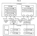
- Figure 1 is a block diagram illustrating one configuration of one or more evolved Node Bs (eNBs) 160 and one or more user equipments (UEs) 102 in which systems and methods for multi-connectivity operation may be implemented.
- the one or more UEs 102 may communicate with one or more eNBs 160 using one or more antennas 122a-n.
- a UE 102 transmits electromagnetic signals to the eNB 160 and receives electromagnetic signals from the eNB 160 using the one or more antennas 122a-n.
- the eNB 160 communicates with the UE 102 using one or more antennas 180a-n.
- one or more of the UEs 102 described herein may be implemented in a signal device in some configurations. For example, multiple UEs 102 may be combined into a single device in some implementations.
- one or more of the eNBs 160 described herein may be implemented in a single device in some configurations. For example, multiple eNBs 160 may be combined into a single device in some implementations.
- a single device may include one or more UEs 102 in accordance with the systems and methods described herein.
- one or more eNBs 160 in accordance with the systems and methods described herein may be implemented as a single device or multiple devices.
- the UE 102 and the eNB 160 may use one or more channels 119, 121 to communicate with each other.
- a UE 102 may transmit information or data to the eNB 160 using one or more uplink channels 121 and signals.
- uplink channels 121 include a physical uplink control channel (PUCCH) and a physical uplink shared channel (PUSCH), etc.
- uplink signals include a demodulation reference signal (DMRS) and a sounding reference signal (SRS), etc.
- the one or more eNBs 160 may also transmit information or data to the one or more UEs 102 using one or more downlink channels 119 and signals, for instance.
- downlink channels 119 include a PDCCH, a PDSCH, etc.
- downlink signals include a primary synchronization signal (PSS), a Cell-specific reference signal (CRS), and a CSI reference channel (CSI-RS), etc.
- PSS primary synchronization signal
- CRS Cell-specific reference signal
- CSI-RS
- Each of the one or more UEs 102 may include one or more transceivers 118, one or more demodulators 114, one or more decoders 108, one or more encoders 150, one or more modulators 154, one or more data buffers 104 and one or more UE operations module 124.
- one or more reception and/or transmission paths may be implemented in the UE 102.
- only a single transceiver 118, decoder 108, demodulator 114, encoder 150 and modulator 154 are illustrated in the UE 102, though multiple parallel elements (e.g., transceivers 118, decoders 108, demodulators 114, encoders 150 and modulators 154) may be implemented.
- the transceiver 118 may include one or more receivers 120 and one or more transmitters 158.
- the one or more receivers 120 may receive signals from the eNB 160 using one or more antennas 122a-n.
- the receiver 120 may receive and downconvert signals to produce one or more received signals 116.
- the one or more received signals 116 may be provided to a demodulator 114.
- the one or more transmitters 158 may transmit signals to the eNB 160 using one or more antennas 122a-n.
- the one or more transmitters 158 may upconvert and transmit one or more modulated signals 156.
- the demodulator 114 may demodulate the one or more received signals 116 to produce one or more demodulated signals 112.
- the one or more demodulated signals 112 may be provided to the decoder 108.
- the UE 102 may use the decoder 108 to decode signals.
- the decoder 108 may produce one or more decoded signals 106, 110.
- a first UE-decoded signal 106 may comprise received payload data, which may be stored in a data buffer 104.
- a second UE-decoded signal 110 may comprise overhead data and/or control data.
- the second UE decoded signal 110 may provide data that may be used by the UE operations module 124 to perform one or more operations.
- module may mean that a particular element or component may be implemented in hardware, software or a combination of hardware and software. However, it should be noted that any element denoted as a “module” herein may alternatively be implemented in hardware.
- the UE operations module 124 may be implemented in hardware, software or a combination of both.
- the UE operations module 124 may enable the UE 102 to communicate with the one or more eNBs 160.
- the UE operations module 124 may include one or more of a UE RRC handover module 126 and a UE SCG addition module 132.
- the UE operations module 124 may include physical (PHY) entities, MAC entities, RLC entities, PDCP entities, and an RRC entity.
- the UE operations module 124 may provide the benefit of utilizing the radio resources of a master cell group (MCG) and a SCG efficiently.
- MCG master cell group
- SCG signaling radio bearer
- An SCG may be added via the MCG.
- the MCG may provide a radio connection between the UE 102 and a master eNB (MeNB) 160.
- the SCG may provide a radio connection between the UE 102 and a secondary eNB (SeNB) 160.
- the UE RRC handover module 126 may receive an RRC connection reconfiguration message (also referred to as RRCConnectionReconfiguration) from a source MeNB 160.
- RRC connection reconfiguration message also referred to as RRCConnectionReconfiguration
- the UE 102 may start synchronizing to the downlink of a target eNB 160.
- the UE RRC handover module 126 may include a MCG module 128 and an SCG module 130.
- the MCG module 128 and the SCG module 130 may handle the PDCP, RLC and MAC entit(ies) of the MCG and the SCG separately.
- the MCG module 128 may reset the MAC entity of the MCG.
- the MCG module 128 may re-establish PDCP entities for all radio bearers (RBs) that are established for the MCG.
- RBs radio bearers
- the MCG module 128 may re-establish RLC entities for all RBs that are established for the MCG.
- the SCG module 130 may release the SCG.
- the SCG module 130 may release the MAC entity of the SCG, if any MAC entity of the SCG is established.
- the SCG module 130 may release the PDCP entities for all RBs that are established for the SCG, if any PDCP entity of the SCG is established.
- the SCG module 130 may release RLC entities for all RBs that are established for SCG, if any RLC entity of the SCG is established.
- the UE RRC handover module 126 may submit an RRC connection reconfiguration complete message to lower layers of the MCG for transmission to the target eNB 160.
- the MAC entity of the MCG of the UE 102 may initiate a random access procedure.
- the UE SCG addition module 132 may perform an SCG addition procedure.
- the UE SCG addition module 132 may receive an RRC connection reconfiguration message.
- the RRC connection reconfiguration message includes SCG configuration parameters 198 for SCG addition and the UE 102 is able to comply with the configuration included in this message, then the UE SCG addition module 132 may start synchronizing to the DL of the target cell of the SCG.
- the UE SCG addition module 132 may establish the MAC entity of the SCG.
- the UE SCG addition module 132 may apply the value of the newUE-Identity as the C-RNTI for the SCG.
- the UE SCG addition module 132 may configure lower layers of the SCG in accordance with a received RRC common message for the SCG.
- the UE SCG addition module 132 may order, by an RRC of the UE 102, a MAC of the SCG of the UE 102 to initiate a random access procedure. It should be noted that for the SCG addition procedure, the UE 102 may not submit any RRC message to lower layers of the SCG. Therefore, the same procedure for initiating a random access procedure during handover (e.g., the submission of the RRC connection reconfiguration complete message) may not be used for SCG addition. Instead, the RRC of the UE 102 may order (e.g., instruct) the MAC of the SCG of the UE 102 to initiate a random access procedure.
- the UE operations module 124 may provide information 148 to the one or more receivers 120. For example, the UE operations module 124 may inform the receiver(s) 120 when or when not to receive transmissions based on the RRC connection reconfiguration message.
- the UE operations module 124 may provide information 138 to the demodulator 114. For example, the UE operations module 124 may inform the demodulator 114 of a modulation pattern anticipated for transmissions from the eNB 160.
- the UE operations module 124 may provide information 136 to the decoder 108. For example, the UE operations module 124 may inform the decoder 108 of an anticipated encoding for transmissions from the eNB 160.
- the UE operations module 124 may provide information 142 to the encoder 150.
- the information 142 may include data to be encoded and/or instructions for encoding.
- the UE operations module 124 may instruct the encoder 150 to encode transmission data 146 and/or other information 142.
- the other information 142 may include the RRC reconfiguration complete message on the MCG and the reconfiguration complete indication on the SCG.
- the encoder 150 may encode transmission data 146 and/or other information 142 provided by the UE operations module 124. For example, encoding the data 146 and/or other information 142 may involve error detection and/or correction coding, mapping data to space, time and/or frequency resources for transmission, multiplexing, etc.
- the encoder 150 may provide encoded data 152 to the modulator 154.
- the UE operations module 124 may provide information 144 to the modulator 154.
- the UE operations module 124 may inform the modulator 154 of a modulation type (e.g., constellation mapping) to be used for transmissions to the eNB 160.
- the modulator 154 may modulate the encoded data 152 to provide one or more modulated signals 156 to the one or more transmitters 158.
- the UE operations module 124 may provide information 140 to the one or more transmitters 158.
- This information 140 may include instructions for the one or more transmitters 158.
- the UE operations module 124 may instruct the one or more transmitters 158 when to transmit a signal to the eNB 160.
- the one or more transmitters 158 may upconvert and transmit the modulated signal(s) 156 to one or more eNBs 160.
- the eNB 160 may include one or more transceivers 176, one or more demodulators 172, one or more decoders 166, one or more encoders 109, one or more modulators 113, one or more data buffers 162 and one or more eNB operations modules 182.
- one or more reception and/or transmission paths may be implemented in an eNB 160.
- only a single transceiver 176, decoder 166, demodulator 172, encoder 109 and modulator 113 are illustrated in the eNB 160, though multiple parallel elements (e.g., transceivers 176, decoders 166, demodulators 172, encoders 109 and modulators 113) may be implemented.
- the transceiver 176 may include one or more receivers 178 and one or more transmitters 117.
- the one or more receivers 178 may receive signals from the UE 102 using one or more antennas 180a-n.
- the receiver 178 may receive and downconvert signals to produce one or more received signals 174.
- the one or more received signals 174 may be provided to a demodulator 172.
- the one or more transmitters 117 may transmit signals to the UE 102 using one or more antennas 180a-n.
- the one or more transmitters 117 may upconvert and transmit one or more modulated signals 115.
- the demodulator 172 may demodulate the one or more received signals 174 to produce one or more demodulated signals 170.
- the one or more demodulated signals 170 may be provided to the decoder 166.
- the eNB 160 may use the decoder 166 to decode signals.
- the decoder 166 may produce one or more decoded signals 164, 168.
- a first eNB-decoded signal 164 may comprise received payload data, which may be stored in a data buffer 162.
- a second eNB-decoded signal 168 may comprise overhead data and/or control data.
- the second eNB decoded signal 168 may provide data (e.g., PUSCH transmission data) that may be used by the eNB operations module 182 to perform one or more operations.
- the eNB operations module 182 may enable the eNB 160 to communicate with the one or more UEs 102.
- the eNB operations module 182 may include one or more of an eNB RRC handover module 184 and an eNB SCG addition module 196.
- the eNB operations module 182 may provide the benefit of utilizing the radio resources of the MCG and the SCG efficiently.
- the eNB operations module 182 may include PHY entities, MAC entities, RLC entities, PDCP entities, and an RRC entity.
- the eNB RRC handover module 184 may send an RRC connection reconfiguration message to the UE 102.
- the RRC connection reconfiguration message may include mobility control information 194.
- the UE 102 may synchronize to the downlink of a target eNB 160.
- the UE 102 may initiate a random access procedure with the target eNB 160.
- the eNB SCG addition module 196 may perform an SCG addition procedure.
- the eNB SCG addition module 196 may send an RRC connection reconfiguration message to the UE 102.
- the RRC connection reconfiguration message may include SCG configuration parameters 198 for SCG addition.
- the SeNB provides SCG configuration parameters 198 for SCG addition to the MeNB.
- the SCG configuration parameters 198 for SCG addition may be provided in an SeNB Addition/Modification Command 1107 as indicated in Figure 11.
- the MeNB may send an RRC connection reconfiguration message to the UE 102.
- the SeNB may handle a random access procedure for the SCG.
- Separation between the eNB RRC handover module 184 and the eNB SCG addition module 196 does not necessarily preclude generating an RRC connection reconfiguration message including the mobility control information 194 and SCG configuration parameters 198 for SCG addition. It is possible for the eNB operations module 182 to generate an RRC connection reconfiguration message including the mobility control information 194 and SCG configuration parameters 198 for SCG addition.
- the SCG addition procedure may be the same as the SCG modification procedure.
- the SCG modification procedure may be realized by SCG release and SCG addition.
- the eNB operations module 182 may control a random access procedure initiated by the UE 102.
- the SCG addition procedure and the random access procedure may be independent.
- SCG addition procedure may include the random access procedure.
- the eNB operations module 182 may handle both the SCG addition procedure and the random access procedure. How the eNB operations module 182 coordinates with the eNB SCG addition module 196 internally is not limited to the following description.
- the eNB SCG addition module 196 may receive a reconfiguration complete indication in a random access procedure.
- the eNB SCG addition module 196 may receive the reconfiguration complete indication from the UE 102 on an uplink shared channel (UL-SCH).
- the reconfiguration complete indication may be a message 3 (Msg3) that includes a C-RNTI MAC control element (C-RNTI MAC CE).
- the reconfiguration complete indication may be a MAC message that includes a specific MAC CE.
- the eNB SCG addition module 196 may send a PDCCH transmission that is addressed to the C-RNTI of the SCG of the UE 102.
- the PDCCH transmission may cause the UE 102 to consider the random access procedure successfully completed.
- the condition that causes the UE 102 to consider the random access procedure successfully completed may be the PDCCH transmission not only that is addressed to the C-RNTI but also that contains an UL grant for a new transmission.
- the eNB SCG addition module 196 may consider the random access procedure concerning the SCG addition for the UE 102 successfully completed.
- the eNB operations module 182 may provide information 190 to the one or more receivers 178. For example, the eNB operations module 182 may inform the receiver(s) 178 when or when not to receive transmissions based on the RRC messages.
- the eNB operations module 182 may provide information 188 to the demodulator 172. For example, the eNB operations module 182 may inform the demodulator 172 of a modulation pattern anticipated for transmissions from the UE(s) 102.
- the eNB operations module 182 may provide information 186 to the decoder 166. For example, the eNB operations module 182 may inform the decoder 166 of an anticipated encoding for transmissions from the UE(s) 102.
- the eNB operations module 182 may provide information 101 to the encoder 109.
- the information 101 may include data to be encoded and/or instructions for encoding.
- the eNB operations module 182 may instruct the encoder 109 to encode transmission data 105 and/or other information 101.
- the eNB operations module 182 may enable the eNB 160 to communicate with one or more network nodes (e.g., a mobility management entity (MME), serving gateway (S-GW), eNBs).
- MME mobility management entity
- S-GW serving gateway
- eNBs may also generate a RRC connection reconfiguration message to be signaled to the UE 102.
- the RRC connection reconfiguration message may or may not include mobility control information 194 and/or SCG configuration parameters 198 for SCG addition.
- the eNB operations module 182 may send, to the other eNB 160, the RRC connection reconfiguration message to be signaled to the UE 102.
- the other eNB 160 may receive the mobility control information 194 and/or SCG configuration parameters 198 for SCG addition from the eNB 160 as a container.
- the eNB 160 may generate a RRC connection reconfiguration message that may include the received container and may send the RRC connection reconfiguration message to the UE 102.
- the eNB 160 may just send a RRC connection reconfiguration message included in the received container.
- the encoder 109 may encode transmission data 105 and/or other information 101 provided by the eNB operations module 182. For example, encoding the data 105 and/or other information 101 may involve error detection and/or correction coding, mapping data to space, time and/or frequency resources for transmission, multiplexing, etc.
- the encoder 109 may provide encoded data 111 to the modulator 113.
- the transmission data 105 may include network data to be relayed to the UE 102.
- the eNB operations module 182 may provide information 103 to the modulator 113.
- This information 103 may include instructions for the modulator 113.
- the eNB operations module 182 may inform the modulator 113 of a modulation type (e.g., constellation mapping) to be used for transmissions to the UE(s) 102.
- the modulator 113 may modulate the encoded data 111 to provide one or more modulated signals 115 to the one or more transmitters 117.
- the eNB operations module 182 may provide information 192 to the one or more transmitters 117.
- This information 192 may include instructions for the one or more transmitters 117.
- the eNB operations module 182 may instruct the one or more transmitters 117 when to (or when not to) transmit a signal to the UE(s) 102.
- the one or more transmitters 117 may upconvert and transmit the modulated signal(s) 115 to one or more UEs 102.
- one or more of the elements or parts thereof included in the eNB(s) 160 and UE(s) 102 may be implemented in hardware.
- one or more of these elements or parts thereof may be implemented as a chip, circuitry or hardware components, etc.
- one or more of the functions or methods described herein may be implemented in and/or performed using hardware.
- one or more of the methods described herein may be implemented in and/or realized using a chipset, an application-specific integrated circuit (ASIC), a large-scale integrated circuit (LSI) or integrated circuit, etc.
- ASIC application-specific integrated circuit
- LSI large-scale integrated circuit
- FIG. 2 is a flow diagram illustrating one implementation of a method 200 for receiving a radio resource control (RRC) message by a UE 102.
- RRC radio resource control
- a source MeNB 160 and a target MeNB 160 may be involved for the UE 102.
- the UE 102 may receive 202 an RRC connection reconfiguration message (also referred to as RRCConnectionReconfiguration) from the source MeNB 160.
- the UE 102 may start a timer (e.g., timer T304) with the timer value set to a value included in the mobility control information 194.
- the timer may be set to a t304 value included in the mobility control information 194.
- the UE 102 may start synchronizing to the downlink of the target PCell.
- the UE 102 may handle the PDCP, RLC and MAC entit(ies) of the MCG and the SCG separately.
- the UE 102 may or may not release the SCG.
- the UE 102 may release 204 the MAC entity of the SCG, if any MAC entity of the SCG is established.
- the UE 102 may reset 204 the MAC entity of the SCG, if any MAC entity of the SCG is established.
- the UE 102 may release the PDCP entities for all RBs that are established for the SCG, if any PDCP entity of the SCG is established.
- the UE 102 may release RLC entities for all RBs that are established for SCG, if any RLC entity of the SCG is established.
- the UE 102 may reset 206 the MAC entity of the MCG.
- the UE 102 may re-establish PDCP entities for all radio bearers (RBs) that are established for the MCG.
- the UE 102 may re-establish RLC entities for all RBs that are established for the MCG.
- the UE 102 may apply the value of the newUE-Identity as the cell-radio network temporary identifier (C-RNTI) for the MCG.
- C-RNTI cell-radio network temporary identifier
- the "newUE-Identiy" may be an information element that is included in the mobility control information 194 that indicates a new UE identity.
- the UE 102 may configure lower layers (e.g., at least one of a PDCP layer, an RLC layer, a MAC layer or a PHY layer) of the MCG in accordance with a received RRC radio resource configuration common message (e.g., radioResourceConfigCommon).
- the UE 102 may configure lower layers of the MCG in accordance with any additional fields, not covered in the RRC radio resource configuration common message, if included in the received mobility control information 194.
- a RACH-ConfigDedicated message which is optionally included in the mobility control information 194, may be provided to the MAC entity for the MCG.
- the UE 102 may submit an RRC connection reconfiguration complete message (e.g., RRCConnectionReconfigurationComplete) to lower layers of the MCG for transmission.
- RRC connection reconfiguration complete message e.g., RRCConnectionReconfigurationComplete
- the MAC entity of the MCG of the UE 102 may initiate a random access procedure.
- the MAC entity of the MCG may detect the arrival of new uplink data and may trigger a buffer status report causing a scheduling request (SR) trigger.
- SR scheduling request
- the MAC entity of the MCG of the UE 102 may use a RACH-ConfigDedicated parameter including the ra-PreambleIndex and the ra-PRACH-MaskIndex.
- the SR may be used for requesting UL-SCH resources for a new transmission.
- the SR may be considered as pending until it is cancelled.
- Pending SR(s) may be cancelled and an SR prohibit timer (e.g., sr-ProhibitTimer) may be stopped when a MAC PDU is assembled and the MAC PDU includes a BSR (Buffer Status Report).
- the BSR report may contain buffer status information up to (and including) the last event that triggered the BSR, or when an UL grant(s) can accommodate all pending data available for transmission.
- the UE 102 may set an SR counter (e.g., SR_COUNTER) to 0.
- the UE 102 may implement the SR procedure of Listing (1) for each transmission time interval (TTI).
- the MAC entity of the MCG will initiate a random access procedure because, in this case, the UE 102 has no valid physical uplink control channel (PUCCH) resource for a scheduling request (SR) configured in any transmission time interval (TTI). It should be noted that in this case there is no direct instruction to initiate a random access procedure from the RRC layer of the UE 102 to the MAC layer. If the MAC of the MCG successfully completes the random access procedure, the UE 102 may stop the timer (e.g., timer T304) and the RRC connection reconfiguration procedure may end.
- PUCCH physical uplink control channel
- SR scheduling request
- TTI transmission time interval
- the UE 102 may initiate a connection re-establishment procedure. Upon initiating the connection re-establishment procedure, the RRC connection reconfiguration procedure may end.
- FIG. 3 is a flow diagram illustrating one implementation of a method 300 for receiving an RRC message by a UE 102.
- an SeNB addition procedure also referred to as an SCG addition procedure
- an RRC connection reconfiguration message (e.g., RRCConnectionReconfiguration) is also used, as described in connection with the handover procedure of Figure 2.
- the UE 102 may receive 302 the RRC connection reconfiguration message.
- the UE 102 may start synchronizing to the DL of the target cell of the SCG.
- the target cell of the SCG may also be referred to as a PCell-like cell, PCell, PSCell, SPCell, SCG PCell, etc.
- the UE 102 may establish the MAC entity of the SCG.
- the UE 102 may apply the value of the newUE-Identity as the C-RNTI for the SCG.
- the newUE-Identity may be an information element that is included in the SCG configuration parameters 198 for SCG addition and indicates a new UE Identity for the SCG.
- the UE 102 may configure lower layers of the SCG in accordance with the received RRC radio resource configuration common message (e.g., radioResourceConfigCommon) for the SCG.
- RRC radio resource configuration common message e.g., radioResourceConfigCommon
- the UE 102 may configure lower layers (e.g., at least one of a PDCP layer, an RLC layer, a MAC layer or a PHY layer) of the SCG in accordance with any additional fields, not included in the radio resource configuration common message for the SCG, if included in the received SCG configuration parameters 198.
- a RACH-ConfigDedicated message which is optionally included in SCG configuration parameters 198, may be provided to the MAC entity for the SCG.
- the UE 102 may order 304, by an RRC of the UE 102, a MAC of the SCG of the UE 102 to initiate a random access procedure. It should be noted that for the SCG addition procedure, the UE 102 may not submit any RRC message to lower layers of the SCG. Therefore, the same procedure for initiating a random access procedure during handover (e.g., the submission of the RRC connection reconfiguration complete message) may not be used for SCG addition. Instead, the RRC of the UE 102 may order 304 (e.g., instruct) the MAC of the SCG of the UE 102 to initiate a random access procedure.
- the RRC of the UE 102 may order 304 (e.g., instruct) the MAC of the SCG of the UE 102 to initiate a random access procedure.
- the RRC of the UE 102 may instruct the MAC of the SCG of the UE 102 to trigger a buffer status report (BSR).
- BSR buffer status report
- the buffer status report may be delivered or transmitted by using a BSR MAC control element.
- the buffer status report may trigger a scheduling request, as described above in Listing (1).
- the MAC of the SCG may initiate a random access procedure because, in this case, the UE 102 has no valid PUCCH resource for an SR configured in any TTI on the SCG.
- the RRC of the UE 102 may instruct the MAC of the SCG of the UE 102 to trigger a specific MAC control element (e.g, reconfiguration complete indication).
- the specific MAC control element may trigger a scheduling request, as described above in Listing (1).
- the MAC of the SCG may initiate a random access procedure because, in this case, the UE 102 has no valid PUCCH resource for an SR configured in any TTI on the SCG.
- the UE 102 may send a reconfiguration complete indication on an UL-SCH.
- the reconfiguration complete indication may be an Msg3 message that includes a C-RNTI MAC CE.
- the reconfiguration complete indication may be a MAC control message that includes a specific MAC control element.
- the UE 102 may monitor the PDCCH for a response from the eNB 160.
- the UE 102 may consider the contention resolution successful. The UE 102 may also considering the random access procedure successfully completed.
- the condition that causes the UE 102 to consider the random access procedure successfully completed may be the PDCCH transmission not only that is addressed to the C-RNTI but also that contains an UL grant for a new transmission.
- FIG. 4 is a flow diagram illustrating one implementation of a method 400 for sending an RRC message by an eNB 160.
- the method 400 may be performed as part of an SeNB addition procedure (also referred to as an SCG addition procedure).
- An eNB 160 may send 402 an RRC connection reconfiguration message to a UE 102.
- the RRC connection reconfiguration message may include SCG configuration parameters 198 for SCG addition, as described above in connection with Figure 3.
- the eNB may control a random access procedure initiated by the UE 102.
- the eNB 160 may receive 404 a random access preamble and a message 3 (Msg3) in a random access procedure.
- the eNB 160 may receive 404 the Msg3 from the UE 102 on an UL-SCH.
- the Msg3 message may be transmitted on an UL-SCH containing a C-RNTI MAC CE or a common control channel (CCCH) service data unit (SDU) as part of a contention resolution in the random access procedure.
- CCCH common control channel
- the eNB 160 may send 406 a PDCCH transmission that is addressed to the C-RNTI of the SCG of the UE 102.
- the PDCCH transmission may cause the UE 102 to consider the random access procedure successfully completed.
- the condition that causes the UE 102 to consider the random access procedure successfully completed may be the PDCCH transmission not only that is addressed to the C-RNTI but also that contains an UL grant for a new transmission.
- the eNB 160 may consider the random access procedure concerning the SCG addition for the UE 102 successfully completed.
- Figure 5 is a block diagram illustrating configurations of E-UTRAN architecture 521 in which systems and methods for multi-connectivity operation may be implemented.
- the UE 502 described in connection with Figure 5 may be implemented in accordance with the UE 102 described in connection with Figure 1.
- the eNBs 560a-b described in connection with Figure 5 may be implemented in accordance with the eNB 160 described in connection with Figure 1.
- the E-UTRAN architecture for multi-connectivity 521 is one example of E-UTRAN architecture that may provide multi-connectivity for a UE 502.
- the UE 502 may connect to E-UTRAN 533 via a Uu interface 539 and a Uux interface 541.
- the E-UTRAN 533 may include a first eNB 560a and a second eNB 560b.
- the eNBs 560a-b may provide the E-UTRA user plane (PDCP/RLC/MAC/PHY) and control plane (RRC) protocol terminations toward the UE 502.
- the eNBs 560a-b may be interconnected with each other by an X2 interface 537.
- the S1 interface 529, 531 may support a many-to-many relation between MMEs 534, serving gateways 527 and eNBs 560a-b.
- the first eNB (e.g., MeNB) 560a and the second eNB (e.g., SeNB) 560b may also be interconnected with each other by means of one or more X interfaces 535, which may or may not be the same as the S1-MME 529 and/or X2 interface 537.
- the eNBs 560 may host a variety of functions.
- the eNBs 560 may host functions for radio resource management (e.g., radio bearer control, radio admission control, connection mobility control, dynamic allocation of resources to UEs 502 in both uplink and downlink (scheduling)).
- the eNBs 560 may also perform IP header compression and encryption of user data stream; selection of an MME 534 at UE 502 attachment when no routing to an MME 534 can be determined from the information provided by the UE 502; and routing of user plane data toward the serving gateway 527.
- the eNBs 560 may additionally perform scheduling and transmission of paging messages (originated from the MME 534); scheduling and transmission of broadcast information (originated from the MME or operation and maintenance (O&M)); measurement and measurement reporting configuration for mobility and scheduling; and scheduling and transmission of the public warning system (PWS) (which may include the earthquake and tsunami warning system (ETWS) and commercial mobile alert system (CMAS)) messages (originated from the MME 534).
- PWS public warning system
- ETWS earthquake and tsunami warning system
- CMAS commercial mobile alert system
- the eNBs 560 may further perform closed subscriber group (CSG) handling and transport level packet marking in the uplink.
- CSG closed subscriber group
- the MME 534 may host a variety of functions. For example, the MME 534 may perform Non-Access Stratum (NAS) signaling; NAS signaling security; access stratum (AS) security control; inter core network (CN) node signaling for mobility between 3GPP access networks; and idle mode UE Reachability (including control and execution of paging retransmission).
- the MME 534 may also perform tracking area list management (for a UE 502 in idle and active mode); packet data network gateway (PDN GW) and S-GW selection; MME 534 selection for handovers with MME 534 change; and Serving GPRS Support Node (SGSN) selection for handovers to 2G or 3G 3GPP access networks.
- the MME 534 may additionally host roaming, authentication, and bearer management functions (including dedicated bearer establishment).
- the MME 534 may provide support for PWS (which includes ETWS and CMAS) message transmission, and may optionally perform paging optimization.
- PWS which includes ETWS and CMAS
- the S-GW 527 may also host the following functions.
- the S-GW 527 may host the local mobility anchor point for inter-eNB 560 handover.
- the S-GW 527 may perform mobility anchoring for inter-3GPP mobility; E-UTRAN idle mode downlink packet buffering and initiation of network triggered service request procedure; lawful interception; and packet routing and forwarding.
- the S-GW 527 may also perform transport level packet marking in the uplink and the downlink; accounting on user and QoS Class Identifier (QCI) granularity for inter-operator charging; and UL and DL charging per UE 502, packet data network (PDN), and QCI.
- QCI QoS Class Identifier
- the radio protocol architecture of E-UTRAN 533 may include the user plane and the control plane.
- the user plane protocol stack may include PDCP, RLC, MAC and PHY sublayers.
- the PDCP, RLC, MAC and PHY sublayers may perform functions (e.g., header compression, ciphering, scheduling, ARQ and HARQ) for the user plane.
- PDCP entities are located in the PDCP sublayer.
- RLC entities are located in the RLC sublayer.
- MAC entities are located in the MAC sublayer.
- the PHY entities are located in the PHY sublayer.
- the control plane may include a control plane protocol stack.
- the PDCP sublayer (terminated in eNB 560a on the network side) may perform functions (e.g., ciphering and integrity protection) for the control plane.
- the RLC and MAC sublayers (terminated in eNB on the network side) may perform the same functions as for the user plane.
- the RRC (terminated in eNB 560a on the network side) may perform the following functions.
- the RRC may perform broadcast functions, paging, RRC connection management, radio bearer (RB) control, mobility functions, UE 502 measurement reporting and control.
- RB radio bearer
- the NAS control protocol may perform, among other things, evolved packet system (EPS) bearer management, authentication, evolved packet system connection management (ECM)-IDLE mobility handling, paging origination in ECM-IDLE and security control.
- EPS evolved packet system
- ECM evolved packet system connection management
- the first eNB 560a and the second eNB 560b may be connected by the S1 interface 529, 531 to the EPC 523.
- the first eNB 560a may be connected to the MME 534 by the S1-MME interface 529.
- the second eNB 560b may be connected to the serving gateway 527 by the S1-U interface 531 (as indicated by a dashed line).
- the first eNB 560a may behave as the MME 534 for the second eNB 560b so that S1-MME interface 529 for the second eNB 560b may be connected (via the X interface 535, for instance) between the first eNB 560a and the second eNB 560b. Therefore, the first eNB 560a may appear to the second eNB 560b as an MME 534 (based on the S1-MME interface 529) and an eNB 560 (based on the X2 interface 537).
- first eNB 560a may also be connected to the serving gateway 527 by the S1-U interface 531 (as indicated by a dashed line). Therefore, the second eNB 560b may not be connected to the EPC 523.
- the first eNB 560a may appear to the second eNB 560b as an MME 534 (based on the S1-MME interface 529), an eNB (based on the X2 interface 537), and an S-GW 527 (based on the S1-U interface 531).
- This architecture 521 may provide a single node S1 interface 529, 531 (e.g., connection) with the EPC 523 for the first eNB 560a and the second eNB 560b.
- a change e.g., handover
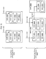
- Figure 6 is a block diagram illustrating one configuration of an E-UTRAN 633 and a UE 602 in which systems and methods for multi-connectivity operation may be implemented.
- the UE 602 and the E-UTRAN 633 described in connection with Figure 6 may be implemented in accordance with corresponding elements described in connection with at least one of Figures 1 and 5.
- a single eNB 660 is assumed to provide multiple serving cells 651 for a UE 602.
- the cells 651 may be controlled (e.g., scheduled) by a single eNB 660.
- each eNB 660 e.g., node
- the UE 602 may connect to both eNBs 660.
- the UE 602 may have one RRC connection with the network.
- One radio interface may provide carrier aggregation.
- one serving cell 651 may provide NAS mobility information (e.g., a tracking area identity (TAI)).
- TAI tracking area identity
- one serving cell 651 may provide a security input.
- This cell 651 may be referred to as the primary cell (PCell).
- the component carrier corresponding to the PCell may be the downlink primary component carrier (DL PCC), while in the uplink it may be the uplink primary component carrier (UL PCC).
- one or more SCells may be configured to form together with the PCell a set of serving cells 651.
- the component carrier corresponding to a SCell may be a downlink secondary component carrier (DL SCC), while in the uplink it may be an uplink secondary component carrier (UL SCC).
- DL SCC downlink secondary component carrier
- UL SCC uplink secondary component carrier
- the configured set of serving cells 651 for the UE 602 may consist of one PCell and one or more SCells.
- the usage of uplink resources by the UE 602 may be configurable.
- the number of DL SCCs configured may be larger than or equal to the number of UL SCCs and no SCell may be configured for usage of uplink resources only.
- each uplink resource may belong to one serving cell 651.
- the number of serving cells 651 that may be configured depends on the aggregation capability of the UE 602.
- the PCell may only be changed using a handover procedure (e.g., with a security key change and a random access channel (RACH) procedure).
- the PCell may be used for transmission of the PUCCH.
- the PCell may not be de-activated. Re-establishment may be triggered when the PCell experiences radio link failure (RLF), not when the SCells experience RLF.
- NAS information may be taken from the PCell.
- RRC 659 may also add, remove or reconfigure SCells for usage with a target PCell.
- dedicated RRC signaling may be used for sending all required system information of the SCell (e.g., while in connected mode, UEs 602 need not acquire broadcasted system information directly from the SCells).
- a UE 602 operating according to Release-12 may be configured with multi-connectivity (which may also be called dual-connectivity, inter-node carrier aggregation, inter-node radio aggregation, multi-flow, multi-cell cluster, multi-Uu, etc.).
- the UE 602 may connect to E-UTRAN 633 with multiple Uu interfaces 539, 541, if configured.
- a UE 602 may be configured to establish an additional radio interface (e.g., radio connection 653) by using one radio interface (radio connection 653).
- one eNB 660 is referred to as a master eNB (MeNB) 660a, which may also be called a primary eNB (PeNB).
- Another eNB 660 is referred to as s secondary eNB (SeNB) 660b.
- the Uu interface 539 (which may be called primary Uu interface) is a radio interface between the UE 602 and the MeNB 660a.
- the Uux interface 541 (which may be called secondary Uu interface) is a radio interface between the UE 602 and the SeNB 660b.
- the UE 602 may not be required to be aware of the MeNB 660a and SeNB 660b as long as the UE 602 is aware of multiple Uu interfaces 539, 541 with the E-UTRAN 415. Also, the E-UTRAN 415 may provide multiple Uu interfaces with the same or different eNBs 660.
- the MeNB 660a and SeNB 660b could be the same eNB 660.
- the multiple Uu interfaces 539, 541 (e.g., multi-connectivity) can be achieved even by a single eNB 660.
- the UE 602 may be able to connect more than one Uux interface 541 (e.g., Uu1, Uu2, Uu3).
- Each Uu interface 539, 541 can have carrier aggregation. Therefore, the UE 602 may be configured with more than one set of serving cells 651 in case of CA. In dual connectivity (i.e, two sets), one set of serving cells 651 may be the MCG 655, another set of serving cells may be the SCG 657.
- Uu interfaces 539, 541 are described herein, but this functionality could be realized by a single Uu interface 539 depending on the definition of Uu interface 539.
- Multi-connectivity may be realized by a single Uu interface 539 or a single radio interface depending on the definition of the interface.
- a radio interface can be defined as an interface between a UE 602 and the E-UTRAN 633, but not an interface between the UE 602 and an eNB 660.
- one radio interface can be defined as an interface between a UE 602 and the E-UTRAN 633 with multi-connectivity. Therefore, the difference between the Uu 539 and Uux 541 above may be considered as a characteristic of cells 651.
- the Uu interface 539 and the Uux interface 541 may be rephrased by a set A of cell(s) and a set B of cell(s), respectively.
- a radio interface and an additional radio interface can be rephrased by a master cell group (MCG) 655 and secondary cell group (SCG) 657, respectively.
- the E-UTRAN 633 may include a MeNB 660a and a SeNB 660b.
- the UE 602 may communicate with the MeNB 660a via a first radio connection 653a.
- the UE 602 may communicate with the SeNB 660b via the second radio connection 653b. While Figure 6 depicts one first radio connection 653a and one second radio connection 653b, the UE 602 may be configured with one first radio connection 653a and one or more second radio connections 653b.
- the MeNB 660a and SeNB 660b may be implemented in accordance with the eNB 160 described in connection with Figure 1.
- the MeNB 660a may provide multiple cells 651a-c for connection to one or more UEs 602.
- the MeNB 660a may provide cell A 651a, cell B 651b and cell C 651c.
- the SeNB 660b may provide multiple cells 651d-f.
- the UE 602 may be configured to transmit/receive on one or more cells (e.g., cell A 651a, cell B 651b and cell C 651c) for the first radio connection 653a (e.g., a master cell group (MCG) 655).
- MCG master cell group
- the UE 602 may also be configured to transmit/receive on one or more other cells (e.g., cell D 651d, cell E 651e and cell F 651f) for the second radio connection 653b (e.g., a secondary cell group 657).
- one or more other cells e.g., cell D 651d, cell E 651e and cell F 651f
- the second radio connection 653b e.g., a secondary cell group 657.
- the MCG 655 may contain one PCell and one or more optional SCell(s).
- the SCG 657 may contain one PCell-like cell (that may be called PCell, primary SCell (PSCell), secondary PCell (SPCell), PCellscg, SCG PCell, etc.) and one or more optional SCell(s). If the UE 602 is configured to transmit/receive on multiple cells 651a-f for a radio connection 653a-b, a carrier aggregation operation may be applied to the radio connection 653a-b. In one configuration, each radio connection 653 may be configured with a primary cell and no, one, or more secondary cell(s).
- At least one radio connection 653 may be configured with a primary cell and no, one, or more secondary cell(s) and the other radio connections 653 may be configured with one or more secondary cell(s). In yet another configuration, at least one radio connection 653 may be configured with a primary cell and no, one, or more secondary cell(s) and the other radio connections 653 may be configured with a PCell-like cell and no, one or more secondary cell(s).
- One MAC entity 661 and one PHY entity 663 may be mapped to one cell group.
- a first MAC entity 661a and a first PHY entity 663a may be mapped to the MCG 655.
- a second MAC entity 661b and a second PHY entity 663b may be mapped to the SCG 657.
- the UE 602 may be configured with one MCG 655 (e.g., the first radio connection 653a) and optionally one or more SCG(s) 657 (e.g., the second connection 653b).
- the MeNB 660a manages and stores UE contexts for the first radio connection 653a.
- the UE contexts may be RRC contexts (e.g., configurations, configured cells 651, security information, etc.), QoS information and UE 602 identities for each UE 602 for configured cells 651 for the UE 602.
- the MeNB 660a may manage and store a first UE context 643a, a second UE context 645 and a third UE context 647.
- the SeNB 660b manages and stores UE contexts for the second radio connection 653b for each UE 602 for configured cells 651 for the UE 602.
- the SeNB 660b may manages and store the first UE context 643b and a fourth UE context 649.
- An eNB 660 can behave as both MeNB 660a and SeNB 660b. Therefore, the eNB 660 may manage and store UE contexts for UEs 602 connected to a first radio connection 653a and UE contexts for UEs 602 connected to a second radio connection 653b.
- the MAC entities 661a-b may have an interface with an RRC entity 659.
- the RRC entity 659 may receive RRC messages (e.g., RRC connection reconfiguration message, connection control message, handover command, etc.) from a RRC entity (not shown) of the E-UTRAN 633.
- the RRC entity 659 may also transmit RRC messages (e.g. RRC connection reconfiguration complete message) to the RRC entity (not shown) of the E-UTRAN 633.
- Figure 7 is a thread diagram illustrating one configuration of an RRC connection reconfiguration procedure 700.
- the UE 702 described in connection with Figure 7 may be implemented in accordance with the UE 102 described in connection with Figure 1.
- the E-UTRAN 733 described in connection with Figure 7 may be implemented in accordance with the E-UTRAN 633 described in connection with Figure 6.
- the purpose of the RRC connection reconfiguration procedure is to modify an RRC connection.
- radio bearers RBs
- a handover may be performed.
- Measurements may be setup, modified and released.
- Secondary cells SCells
- SCells Secondary cells
- SCG secondary cell group
- SeNB 660b a secondary cell group 657
- non-access stratum (NAS) dedicated information may be transferred from the E-UTRAN 715 to the UE 702.
- the E-UTRAN 733 may send 701 an RRC connection reconfiguration message to the UE 702. If the RRC connection reconfiguration message includes mobility control information 194, the UE 702 may perform a handover operation. This may be accomplished as described below in connection with Figure 2. If the RRC connection reconfiguration message includes SCG configuration parameters 198 for SCG 657 addition, then the UE 702 may perform an SCG 657 addition procedure as described in connection with Figure 3.
- the UE 702 may send 703a an RRC connection reconfiguration complete message on the MCG 655 to the E-UTRAN 733.
- the UE 702 does not submit any RRC message to lower layers of the SCG 657. Instead, the RRC 659 of the UE 702 may order 703a the MAC 661 of the SCG 657 of the UE 702 to initiate a random access procedure on the SCG 657.
- the UE 702 may send 703a an RRC connection reconfiguration complete message on the MCG 655 to the E-UTRAN 733.
- the UE 702 may attempt to re-establish 703b the RRC connection, which may involve the resumption of signaling radio bearer (SRB1) operation, the re-activation of security and the configuration of only the PCell.
- SRB1 signaling radio bearer
- Figure 8 is a thread diagram illustrating one configuration of a non-contention based random access procedure 800.
- the UE 802 described in connection with Figure 8 may be implemented in accordance with the UE 102 described in connection with Figure 1.
- the eNB 860 described in connection with Figure 8 may be implemented in accordance with the eNB 160 described in connection with Figure 1.
- the eNB 860 may send 801 a random access preamble assignment. For example, the eNB 860 may assign the UE 802 a non-contention random access preamble (e.g., a dedicated random access preamble that is not within a set informed in broadcast signaling or a radio resource configuration common message). In some implementations, the eNB 860 may assign 801 the random access preamble via a dedicated signaling in a downlink (via a dedicated RACH preamble identity, for example) (message 0).
- a dedicated signaling in a downlink via a dedicated RACH preamble identity, for example
- the UE 802 may then send 803 the assigned non-contention random access preamble to the eNB 860 (message 1). In some implementations, the UE 802 may send 803 the assigned non-contention random access preamble on a RACH in an uplink transmission.
- the eNB 860 may then send 805 a random access response to the UE 802 (message 2).
- the random access response may be generated by the MAC on a downlink shared channel (DL-SCH).
- the UE 802 may receive the random access response.
- the random access response may include an uplink grant.
- Figure 9 is a thread diagram illustrating one configuration of a contention-based random access procedure 900.
- the UE 902 described in connection with Figure 9 may be implemented in accordance with the UE 102 described in connection with Figure 1.
- the eNB 960 described in connection with Figure 9 may be implemented in accordance with the eNB 160 described in connection with Figure 1.
- the UE 902 may select a random access preamble. For example, the UE 902 may select a random access preamble randomly from a set that is informed in broadcast signaling or a radio resource configuration common message. The UE 902 may then send 901 the randomly selected random access preamble to the eNB 960 (on a RACH in an uplink transmission, for example) (message 1).
- the eNB 960 may send 903 a random access response (message 2).
- the UE 902 may receive the random access response.
- the random access response may include a temporary C-RNTI and an uplink grant.
- the random access response may be generated by the MAC on the DL-SCH.
- the UE 902 may then send 905 an Msg3 on a scheduled uplink resource on an UL-SCH (message 3, Msg3).
- the UE 902 may transmit 905 the Msg3 on an uplink resource scheduled by the uplink grant received in the random access response or retransmit the Msg3 on an uplink resource scheduled by PDCCH addressed to the temporary C-RNTI.
- an Msg3 message may include at least a C-RNTI MAC CE or a CCCH SDU. If the random access procedure is within a RRC connection establishment procedure, an Msg3 message includes at least the CCCH SDU. If the RRC order initiates the random access procedure, an Msg3 message includes at least a C-RNTI MAC CE. In case of the RRC order, the Msg3 message may include a special MAC CE for reconfiguration complete indication to the SeNB.
- the UE 902 may start a contention resolution timer (e.g., mac-ContentionResolutionTimer).
- the contention resolution timer may specify the number of consecutive subframe(s) during which the UE 902 may monitor the PDCCH after the Msg3 is transmitted.
- the contention resolution timer may run once it is started, until it is stopped or until it expires, otherwise the contention resolution timer is not running.
- the contention resolution timer may be started if it is not running or restarted if it is running.
- the contention resolution timer may be started or restarted from its initial value.
- the UE 902 may restart the contention resolution timer at each hybrid automatic repeat request (HARQ) retransmission. Regardless of the the possible occurrence of a measurement gap, the UE 902 may monitor the PDCCH until the contention resolution timer expires or is stopped.
- HARQ hybrid automatic repeat request
- the eNB 960 may send 907 a contention resolution, which may be received by the UE 902.
- the contention resolution may be sent 907 on the PDCCH.
- the contention resolution may include information that confirms that the UE 902 is identified.
- the lower layers (e.g., PHY layer) of the UE 902 may provide notification of the reception of the PDCCH transmission.
- the UE 902 may consider the contention resolution successful.
- the UL grant is a scheduling command for PUSCH.
- the UL grant may provide PUSCH resource assignment and indication of new transmission or retransmission.
- the UE 902 may stop the contention resolution timer.
- the UE 902 may discard the temporary C-RNTI.
- the UE 902 may also consider the random access procedure successfully completed.
- the UE 902 may consider the contention resolution successful.
- the UE 902 may stop the contention resolution timer.
- the UE 902 may discard the temporary C-RNTI.
- the UE 902 may also consider the random access procedure successfully completed.
- Figure 10 is a block diagram illustrating a first user plane (UP) architecture 1065a and a second UP architecture 1065b.
- the S1-U interface 1031 terminates at an MeNB 1060a and an SeNB 1060b.
- the UP of the MeNB 1060a includes a PDCP 1067a an RLC 1069a and a MAC 1061a.
- the UP of the SeNB 1060b includes a PDCP 1067b an RLC 1069b and a MAC 1061b.
- the PDCP 1067a of the MeNB 1060a is independent of the PDCP 1067b of the SeNB 1060b. In other words, for the first UP architecture 1065a there is no bearer split.
- the S1-U interface 1031 terminates at the MeNB 1060c.
- the UP of the MeNB 1060c includes a first PDCP 1067c and second PDCP 1067d, a first RLC 1069c and second RLC 1069d and a first MAC 1061c and second MAC 1061d.
- the UP of the SeNB 1060b includes an RLC 1069e and a MAC 1061e.
- the second PDCP 1067d of the MeNB 1060c is coupled to the RLC 1069e of the SeNB 1060b via an X2 interface 1037.
- the second UP architecture 1065b has independent RLCs 1069 for the split bearers.
- Both a contention-free random access procedure (as described in connection with Figure 8) and a contention-based random access procedure (as described in connection with Figure 9) are supported towards the SeNB 1060b,d.
- the random access response message is sent from the eNB 1060 to which the random access preamble was sent.
- a parallel random access procedure is supported if the random access preamble transmission is not overlapped. There is no requirement to coordinate physical random access channel (PRACH) resources in the network side.
- PRACH physical random access channel
- the random access procedure is initiated by a PDCCH order or by the MAC sublayer itself. If this is a MAC entity of the SCG 657, the random access procedure may also be initiated by an RRC order as well.
- a random access procedure on an SCell may only be initiated by a PDCCH order. If a UE 102 receives a PDCCH transmission consistent with a PDCCH order masked with its C-RNTI, and for a specific serving cell 651, the UE 102 may initiate a random access procedure on the serving cell.
- a PDCCH order or an RRC optionally indicate the ra-PreambleIndex and the ra-PRACH-MaskIndex.
- the PDCCH order indicates the ra-PreambleIndex with a value different from 000000 and the ra-PRACH-MaskIndex.
- the pTAG preamble transmission on PRACH and reception of a PDCCH order may be supported for the PCell and the PCell-like cell.
- the UE 102 may send BSR information related to the specific bearer towards the eNB 1060 to which the corresponding bearer belongs.
- BSR information related to the specific bearer towards the eNB 1060 to which the corresponding bearer belongs.
- Separate discontinuous reception (DRX) configurations may be supported for the MeNB 1060a,c and the SeNB 1060b,d and separate DRX operations (e.g., timers and active time) should be allowed for MeNB 1060a,c and SeNB 1060b,d. From a UE power consumption point of view, DRX coordination would be beneficial for UE 102 power consumption.
- the MeNB 1060a,c can activate and deactivate cells 651 associated with the MeNB 1060a,c.
- the SeNB 1060b,d can activate and deactivate cells 651 associated with the SeNB 1060b,d.
- the MAC entity 661 of the UE 102 may be configured per cell group (e.g., one MAC 661 for the MCG 655 and the other MAC 661 for the SCG 657).
- the maximum number of serving cells 651 per UE 102 for carrier aggregation is 5.
- Carrier aggregation may be supported in the MeNB 1060a,c and the SeNB 1060b,d.
- the MeNB 1060a,c and the SeNB 1060b,d may have multiple serving cells 651 for a UE 102.
- a UE 102 may be connected to one MeNB 1060a,c and one SeNB 1060b,d.
- a timing advance group (TAG) may only comprise cells 651 of one eNB 1060.
- the maximum number of TAGs per UE 102 for carrier aggregation is 4.
- the MCG 655 and the SCG 657 may operate either in the same or in different duplex schemes.
- the SeNB 1060b,d may have one special cell 651 (e.g., PCell-like cell) containing at least PUCCH functionality, and potentially also some other PCell functionality. However, it is not necessary to duplicate all PCell functionality for the special cell 651. For the special cell 651 in the SCG 657, there is no need to provide NAS security and NAS mobility functions in the SeNB 1060b,d. At least one cell 651 in the SeNB 1060b,d has configured UL and one cell 651 is configured with PUCCH resources.
- one special cell 651 e.g., PCell-like cell
- Radio link monitoring No radio link monitoring (RLM) is needed on a cell 651 not carrying PUCCH in the SeNB 1060b,d.
- Radio link failure (RLF), if supported, of any cell 651 of the SCG 657 does not trigger RRC connection re-establishment.
- the cell 651 in the SeNB 1060b,d which is configured with PUCCH resources may not be cross-carrier scheduled.
- the first UP architecture 1065a and the second user plane architecture 1065b may be implemented by RRC configuration. Deviations in the protocol stack for different configurations should be limited. For instance, a new specification of PDCP-SeNB should be not introduced.
- some bearers of a UE 102 may be split (as in the second UP architecture 1065b) while other bearers are only served by the MeNB 1060a,c.
- some bearers of a UE 102 may be served by the SeNB 1060b,d (as in the first UP architecture 1065a) while others are only served by the MeNB 1060a,c.
- RLC status PDUs may transmitted to corresponding eNBs 1060 via the corresponding Uu interface 539 or Uux interface 541.
- Figure 11 is a thread diagram illustrating one configuration of SeNB 1160b addition and modification 1100.
- the UE 1102 described in connection with Figure 11 may be implemented in accordance with the UE 102 described in connection with Figure 1.
- the MeNB 1160a and the SeNB 1160b described in connection with Figure 11 may be implemented in accordance with the eNB 160 described in connection with Figure 1.
- Figure 11 depicts the overall signaling scheme for the addition and modification of SeNB 1160b resources (e.g., SCG addition) for multi-connectivity operation. It should be noted that this signaling scheme illustrates the similarities between addition and modification signaling schemes.
- S1-MME 529 and X2-C 537 signaling that is relevant only for the first UP architecture 1065a is shown with dashed lines (steps 1111, 1113 and 1121-1125). It is assumed that the S-GW 1127 does not change.
- the MeNB 1160a may decide 1101a to request the SeNB 1160b to add or modify radio resources for a specific E-UTRAN radio access bearer (E-RAB).
- the decision 1101a to request the SeNB 1160b to add or modify radio resources may be a radio resource management (RRM) decision.
- the SeNB 1160b may decide 1101b to modify radio resources for a specific E-RAB.
- the decision 1101b to modify radio resources may be an RRM decision.
- the SeNB 1160b and the MeNB 1160a may coordinate to ensure that the capabilities of the UE 1102 are not exceeded.
- the MeNB 1160a may send 1103 an SeNB addition/modification request to the SeNB 1160b to allocate or modify radio resources.
- the SeNB addition/modification request may include E-RAB characteristics (e.g., E-RAB parameters and transport network layer (TNL) address information corresponding to an UP architecture 1065), UE 1102 capabilities, the current radio resource configuration of the UE 1102, etc.
- the RRM of the SeNB 1160b may decide 1105 whether to admit the resource request. If the RRM entity in the SeNB 1160b is able to admit the resource request, then the SeNB 1160b may configure the respective radio resources and respective transport network resources (based on the UP architecture 1065).
- the SeNB 1160b may also allocate a dedicated RACH preamble for the UE 1102 so that synchronisation of the SeNB 1160b radio resource configuration may be performed.
- the SeNB 1160b may send 1107 an SeNB addition/modification command to the MeNB 1160a.
- the SeNB 1160b may provide the new radio resource configuration to the MeNB 1160a.
- the SeNB addition/modification command may include S1 interface DL TNL address information for the respective E-RAB.
- the SeNB addition/modification command may include X2 interface DL TNL address information.
- the MeNB 1160a may endorse the new radio resource configuration and may trigger the UE 1102 to apply it.
- the MeNB 1160a may send 1109 an RRC connection reconfiguration message (e.g., an RRC connection reconfiguration message that includes SCG configuration parameters 198 for SCG addition) to the UE 1102.
- the UE 1102 may start to apply the new radio resource configuration.
- the MeNB 1160a may, dependent on respective E-RAB characteristics, take actions to minimise service interruption due to activation of multi-connectivity.
- the MeNB 1160a may send 1111 a sequence number (SN) status report to the SeNB 1160b.
- the MeNB 1160a may perform 1113 data forwarding to the SeNB 1160b.
- the UP resources established for data forwarding for the first UP architecture 1065a may be released explicitly.
- the UE 1102 may send 1115 an RRC connection reconfiguration complete message to the MeNB 1160a.
- the UE 1102 may perform synchronisation towards a cell 651 of the SeNB 1160b.
- the UE 1102 may perform 1117 a random access procedure with the SeNB 1160b, if needed.
- the RRC connection reconfiguration complete message may be sent 1115 after the synchronisation procedure 1117 or may be before the synchronisation procedure 1117.
- transmission of user plane data from the SeNB 1160b to the UE 1102 may take place after step 1115 or 1117 depending on the synchronisation procedure.
- the SeNB 1160b may send 1119 a SeNB addition/modification complete message to the MeNB 1160a.
- the SeNB 1160b reports to the MeNB 1160a the detection of synchronisation with the UE 1102, confirming that the new configuration is in use. Receipt of the SeNB addition/modification complete message by the MeNB 1160a successfully completes the overall SeNB addition/modification procedure on the X2 interface.
- Step 1119 may be either necessary as described above or in the reverse direction (from MeNB 1160a to SeNB 1160b).
- an update of the UP path towards the EPC 523 may be performed.
- the MeNB 1160a may send 1121 an E-RAB modification indication to the MME 1134.
- the MME 1134 and the S-GW 1127 may perform 1123 bearer modification.
- the MME 1134 may send 1125 an E-RAB modification confirmation to the MeNB 1160a.
- Figure 12 illustrates various components that may be utilized in a UE 1202.
- the UE 1202 described in connection with Figure 12 may be implemented in accordance with the UE 102 described in connection with Figure 1.
- the UE 1202 includes a processor 1281 that controls operation of the UE 1202.
- the processor 1281 may also be referred to as a central processing unit (CPU).
- Memory 1287 which may include read-only memory (ROM), random access memory (RAM), a combination of the two or any type of device that may store information, provides instructions 1283a and data 1285a to the processor 1281.
- a portion of the memory 1287 may also include non-volatile random access memory (NVRAM).
- Instructions 1283b and data 1285b may also reside in the processor 1281.
- Instructions 1283b and/or data 1285b loaded into the processor 1281 may also include instructions 1283a and/or data 1285a from memory 1287 that were loaded for execution or processing by the processor 1281.
- the instructions 1283b may be executed by the processor 1281 to implement one or more of the methods 200 and 300 described above.
- the UE 1202 may also include a housing that contains one or more transmitters 1258 and one or more receivers 1220 to allow transmission and reception of data.
- the transmitter(s) 1258 and receiver(s) 1220 may be combined into one or more transceivers 1218.
- One or more antennas 1222a-n are attached to the housing and electrically coupled to the transceiver 1218.
- the various components of the UE 1202 are coupled together by a bus system 1289, which may include a power bus, a control signal bus and a status signal bus, in addition to a data bus. However, for the sake of clarity, the various buses are illustrated in Figure 12 as the bus system 1289.
- the UE 1202 may also include a digital signal processor (DSP) 1291 for use in processing signals.
- DSP digital signal processor
- the UE 1202 may also include a communications interface 1293 that provides user access to the functions of the UE 1202.
- the UE 1202 illustrated in Figure 12 is a functional block diagram rather than a listing of specific components.
- FIG. 13 illustrates various components that may be utilized in an eNB 1360.
- the eNB 1360 described in connection with Figure 13 may be implemented in accordance with the eNB 160 described in connection with Figure 1.
- the eNB 1360 includes a processor 1381 that controls operation of the eNB 1360.
- the processor 1381 may also be referred to as a central processing unit (CPU).
- Memory 1387 which may include read-only memory (ROM), random access memory (RAM), a combination of the two or any type of device that may store information, provides instructions 1383a and data 1385a to the processor 1381.
- a portion of the memory 1387 may also include non-volatile random access memory (NVRAM).
- Instructions 1383b and data 1385b may also reside in the processor 1381.
- Instructions 1383b and/or data 1385b loaded into the processor 1381 may also include instructions 1383a and/or data 1385a from memory 1387 that were loaded for execution or processing by the processor 1381.
- the instructions 1383b may be executed by the processor 1381 to implement method 400 described above.
- the eNB 1360 may also include a housing that contains one or more transmitters 1317 and one or more receivers 1378 to allow transmission and reception of data.
- the transmitter(s) 1317 and receiver(s) 1378 may be combined into one or more transceivers 1376.
- One or more antennas 1380a-n are attached to the housing and electrically coupled to the transceiver 1376.
- the various components of the eNB 1360 are coupled together by a bus system 1389, which may include a power bus, a control signal bus and a status signal bus, in addition to a data bus. However, for the sake of clarity, the various buses are illustrated in Figure 13 as the bus system 1389.
- the eNB 1360 may also include a digital signal processor (DSP) 1391 for use in processing signals.
- DSP digital signal processor
- the eNB 1360 may also include a communications interface 1393 that provides user access to the functions of the eNB 1360.
- the eNB 1360 illustrated in Figure 13 is a functional block diagram rather than a listing of specific components.
- Figure 14 is a block diagram illustrating one configuration of a UE 1402 in which systems and methods for sending feedback information may be implemented.
- the UE 1402 includes transmit means 1458, receive means 1420 and control means 1424.
- the transmit means 1458, receive means 1420 and control means 1424 may be configured to perform one or more of the functions described in connection with Figure 2 and Figure 3 above.
- Figure 12 above illustrates one example of a concrete apparatus structure of Figure 14.
- Other various structures may be implemented to realize one or more of the functions of Figure 2 and Figure 3.
- a DSP may be realized by software.
- Figure 15 is a block diagram illustrating one configuration of an eNB 1560 in which systems and methods for receiving feedback information may be implemented.
- the eNB 1560 includes transmit means 1517, receive means 1578 and control means 1582.
- the transmit means 1517, receive means 1578 and control means 1582 may be configured to perform one or more of the functions described in connection with Figure 4 above.
- Figure 13 above illustrates one example of a concrete apparatus structure of Figure 15.
- Other various structures may be implemented to realize one or more of the functions of Figure 4.
- a DSP may be realized by software.
- computer-readable medium refers to any available medium that can be accessed by a computer or a processor.
- computer-readable medium may denote a computer- and/or processor-readable medium that is non-transitory and tangible.
- a computer-readable or processor-readable medium may comprise RAM, ROM, EEPROM, CD-ROM or other optical disk storage, magnetic disk storage or other magnetic storage devices, or any other medium that can be used to carry or store desired program code in the form of instructions or data structures and that can be accessed by a computer or processor.
- Disk and disc includes compact disc (CD), laser disc, optical disc, digital versatile disc (DVD), floppy disk and Blu-ray (registered trademark) disc where disks usually reproduce data magnetically, while discs reproduce data optically with lasers.
- one or more of the methods described herein may be implemented in and/or performed using hardware.
- one or more of the methods described herein may be implemented in and/or realized using a chipset, an application-specific integrated circuit (ASIC), a large-scale integrated circuit (LSI) or integrated circuit, etc.
- ASIC application-specific integrated circuit
- LSI large-scale integrated circuit
- Each of the methods disclosed herein comprises one or more steps or actions for achieving the described method.
- the method steps and/or actions may be interchanged with one another and/or combined into a single step without departing from the scope of the claims.
- the order and/or use of specific steps and/or actions may be modified without departing from the scope of the claims.
Landscapes
- Engineering & Computer Science (AREA)
- Computer Networks & Wireless Communication (AREA)
- Signal Processing (AREA)
- Mobile Radio Communication Systems (AREA)
- Communication Control (AREA)
Priority Applications (3)
| Application Number | Priority Date | Filing Date | Title |
|---|---|---|---|
| JP2016535198A JP6438478B2 (ja) | 2013-12-13 | 2014-12-09 | マルチ接続性オペレーションのためのシステムおよび方法 |
| EP14869913.5A EP3081035B1 (en) | 2013-12-13 | 2014-12-09 | Method, user equipment and computer-readable medium for multi-connectivity operation |
| CN201480067292.9A CN105814942B (zh) | 2013-12-13 | 2014-12-09 | 针对多连接操作的系统和方法 |
Applications Claiming Priority (2)
| Application Number | Priority Date | Filing Date | Title |
|---|---|---|---|
| US14/106,583 | 2013-12-13 | ||
| US14/106,583 US9756678B2 (en) | 2013-12-13 | 2013-12-13 | Systems and methods for multi-connectivity operation |
Publications (1)
| Publication Number | Publication Date |
|---|---|
| WO2015087545A1 true WO2015087545A1 (en) | 2015-06-18 |
Family
ID=53370208
Family Applications (1)
| Application Number | Title | Priority Date | Filing Date |
|---|---|---|---|
| PCT/JP2014/006149 WO2015087545A1 (en) | 2013-12-13 | 2014-12-09 | Systems and methods for multi-connectivity operation |
Country Status (5)
| Country | Link |
|---|---|
| US (1) | US9756678B2 (zh) |
| EP (1) | EP3081035B1 (zh) |
| JP (1) | JP6438478B2 (zh) |
| CN (1) | CN105814942B (zh) |
| WO (1) | WO2015087545A1 (zh) |
Cited By (1)
| Publication number | Priority date | Publication date | Assignee | Title |
|---|---|---|---|---|
| CN110708766A (zh) * | 2018-07-10 | 2020-01-17 | 夏普株式会社 | 用户设备的控制方法以及用户设备 |
Families Citing this family (49)
| Publication number | Priority date | Publication date | Assignee | Title |
|---|---|---|---|---|
| JP6312992B2 (ja) * | 2013-06-27 | 2018-04-18 | 株式会社Nttドコモ | 移動局 |
| US10362615B2 (en) * | 2013-10-30 | 2019-07-23 | Kt Corporation | Method and apparatus for configuring dual connection in mobile communication network |
| EP3585103A1 (en) | 2013-12-19 | 2019-12-25 | Guangdong Oppo Mobile Telecommunications Corp., Ltd. | Network access through a second wireless network |
| JP6151801B2 (ja) | 2013-12-24 | 2017-06-21 | 京セラ株式会社 | マスタ基地局 |
| EP3092864B1 (en) * | 2014-01-08 | 2019-08-21 | LG Electronics Inc. | C-rnti collision in dual connectivity |
| EP3099118B1 (en) * | 2014-01-22 | 2019-06-12 | LG Electronics Inc. | Method for performing power control, and user equipment |
| CN110784919B (zh) * | 2014-01-29 | 2022-10-11 | 三星电子株式会社 | 移动通信系统中基于多载波的数据发射方法和设备 |
| KR102307452B1 (ko) * | 2014-01-29 | 2021-10-05 | 삼성전자주식회사 | 이동 통신 시스템에서 랜덤 액세스를 수행하는 방법 및 장치 |
| KR102369016B1 (ko) * | 2014-01-29 | 2022-03-03 | 삼성전자주식회사 | 이동 통신 시스템에서 복수의 캐리어를 이용하는 데이터 송수신 방법 및 장치 |
| EP3101972A4 (en) * | 2014-01-31 | 2018-01-31 | Kyocera Corporation | Communication control method |
| US9894519B2 (en) * | 2014-03-14 | 2018-02-13 | Htc Corporation | Connection modification method applicable to user equipment and base station |
| US9936427B2 (en) * | 2014-03-14 | 2018-04-03 | Intel Corporation | Systems and methods for joint handover of user equipment and secondary cell group in 3GPP LTE dual connectivity |
| CN104955064B (zh) * | 2014-03-28 | 2019-01-11 | 上海诺基亚贝尔股份有限公司 | 一种在双连接系统中处理用户设备端rlc/pdcp实体的方法与设备 |
| WO2016038763A1 (ja) * | 2014-09-12 | 2016-03-17 | 日本電気株式会社 | 無線局、無線端末、及び端末測定のための方法 |
| US9743319B2 (en) * | 2014-11-12 | 2017-08-22 | Htc Corporation | Device and method of handling network configurations |
| JP6920061B2 (ja) * | 2015-01-08 | 2021-08-18 | シャープ株式会社 | 端末装置、基地局装置、無線通信方法および集積回路 |
| EP3245816B1 (en) * | 2015-01-12 | 2021-03-03 | Nokia Solutions and Networks Oy | Improving communication efficiency |
| JP2018050089A (ja) * | 2015-01-29 | 2018-03-29 | シャープ株式会社 | 端末装置、基地局装置、集積回路、および、通信方法 |
| WO2016163835A1 (en) * | 2015-04-09 | 2016-10-13 | Lg Electronics Inc. | Method and apparatus for handling l2 entity in channel change for relaying in wireless communication system |
| EP3125643B1 (en) * | 2015-07-31 | 2019-04-03 | Panasonic Intellectual Property Corporation of America | Improved scheduling mechanism for prose relays serving remote ues |
| US20170111923A1 (en) * | 2015-10-14 | 2017-04-20 | Sharp Laboratories Of America, Inc. | User equipments, base stations and methods for low latency radio communications |
| US10959138B2 (en) * | 2016-03-30 | 2021-03-23 | Sharp Kabushiki Kaisha | Terminal apparatus, base station apparatus, communication method, and control method |
| US10855399B2 (en) * | 2016-06-03 | 2020-12-01 | Htc Corporation | Device and method of handling dual connectivity |
| KR102502279B1 (ko) * | 2016-07-08 | 2023-02-21 | 삼성전자 주식회사 | 무선 통신 시스템에 있어서 핸드오버를 수행하는 방법 및 장치 |
| CN108243468B (zh) | 2016-12-23 | 2021-09-21 | 夏普株式会社 | 用户移动性方法和设备 |
| KR102174936B1 (ko) * | 2017-03-24 | 2020-11-05 | 주식회사 케이티 | 이종 네트워크에서의 단말의 이동성 제어 방법 및 그 장치 |
| CN108924931B (zh) * | 2017-03-24 | 2024-05-07 | 中兴通讯股份有限公司 | 一种无线资源配置方法、装置及用户设备、网络节点 |
| CN113055880A (zh) | 2017-05-05 | 2021-06-29 | 华为技术有限公司 | 一种数据传输方法、相关设备及系统 |
| WO2018213396A1 (en) * | 2017-05-16 | 2018-11-22 | Intel IP Corporation | Per ue network controlled small gap (ncsg) signalling |
| CN113840344A (zh) * | 2017-08-01 | 2021-12-24 | 上海朗帛通信技术有限公司 | 一种被用于无线通信的用户、基站中的方法和装置 |
| WO2019031797A1 (en) * | 2017-08-08 | 2019-02-14 | Lg Electronics Inc. | METHOD FOR REALIZING A RANDOM ACCESS PROCEDURE IN A WIRELESS COMMUNICATION SYSTEM AND DEVICE THEREFOR |
| EP3659391B1 (en) * | 2017-08-11 | 2024-05-01 | Samsung Electronics Co., Ltd. | Method for performing bearer type change of a plurality of bearers configured for user equipment |
| JP6980906B2 (ja) * | 2017-09-15 | 2021-12-15 | オッポ広東移動通信有限公司Guangdong Oppo Mobile Telecommunications Corp., Ltd. | スケジューリング要求の構成方法、端末装置及びコンピュータ記憶媒体 |
| CN109587805B (zh) * | 2017-09-28 | 2021-02-19 | 维沃移动通信有限公司 | 调度请求的处理方法及终端设备 |
| DK3713323T3 (da) * | 2017-11-15 | 2024-01-22 | Ntt Docomo Inc | Radiokommunikationssystem, fremgangsmåde og radiobasisstation |
| EP3530021A1 (en) * | 2018-01-10 | 2019-08-28 | ZTE Corporation | Releasing signaling radio bearers for cell groups |
| US10743321B2 (en) * | 2018-02-23 | 2020-08-11 | Mediatek Inc | Default beam for uplink transmission after beam failure recovery |
| US11330653B2 (en) * | 2018-06-14 | 2022-05-10 | Qualcomm Incorporated | Mobility robustness and spatial reliability using multi-connectivity |
| CN112840739B (zh) * | 2018-10-26 | 2024-04-12 | 谷歌有限责任公司 | 资源控制状态更改和多节点连接性的高效处理 |
| US10952083B2 (en) | 2018-11-12 | 2021-03-16 | At&T Intellectual Property I, L.P. | Network optimization and control for wireless networks |
| CN111224758B (zh) * | 2018-11-23 | 2022-04-05 | 大唐移动通信设备有限公司 | 一种重复传输指示方法、基站及终端 |
| KR20200114303A (ko) * | 2019-03-28 | 2020-10-07 | 삼성전자주식회사 | 차세대 이동 통신 시스템에서 데이터 송수신 중단이 없는 핸드오버 방법 및 장치 |
| JP6864045B2 (ja) * | 2019-07-17 | 2021-04-21 | シャープ株式会社 | 端末装置、基地局装置、および、方法 |
| US11706672B2 (en) * | 2019-09-06 | 2023-07-18 | Qualcomm Incorporated | Techniques for prioritization associated with a cell group change |
| KR20220098159A (ko) * | 2019-11-07 | 2022-07-11 | 오피노 엘엘씨 | 셀 구성 파라미터 |
| WO2021159422A1 (en) | 2020-02-14 | 2021-08-19 | Qualcomm Incorporated | Aperiodic measurement configuration |
| CN113543168A (zh) * | 2020-04-21 | 2021-10-22 | 夏普株式会社 | 由用户设备执行的方法及用户设备 |
| KR20220032484A (ko) | 2020-09-07 | 2022-03-15 | 아서스테크 컴퓨터 인코포레이션 | 무선 통신 시스템에서 mac 리셋에 관한 이동성 절차를 위한 방법 및 장치 |
| CN113347694B (zh) * | 2021-06-30 | 2022-12-06 | 锐迪科微电子科技(上海)有限公司 | 无线承载释放方法、装置、设备和介质 |
Family Cites Families (20)
| Publication number | Priority date | Publication date | Assignee | Title |
|---|---|---|---|---|
| RU2558733C2 (ru) * | 2009-11-19 | 2015-08-10 | Интердиджитал Пэйтент Холдингз, Инк. | Активация/деактивация компонентных несущих в системах с несколькими несущими |
| EP3913842A1 (en) * | 2010-01-11 | 2021-11-24 | QUALCOMM Incorporated | Method for communicating with data through component carriers in mobile communication system to which carrier aggregation method is applied and apparatus therefor |
| US8649363B2 (en) * | 2010-06-01 | 2014-02-11 | Htc Corporation | Method of hybrid automatic repeat request entity handling and communication device thereof |
| JP5499006B2 (ja) * | 2010-11-02 | 2014-05-21 | 創新音▲速▼股▲ふん▼有限公司 | 無線通信システムのハンドオーバー中のセカンダリセル解放の方法及び装置 |
| US9204289B2 (en) * | 2011-02-15 | 2015-12-01 | Samsung Electronics Co., Ltd. | Method and apparatus of handling user equipment category in wireless communication system |
| CN110519847B (zh) * | 2011-07-29 | 2023-11-24 | 交互数字专利控股公司 | 用于多无线电接入技术无线系统中的无线电资源管理的方法和设备 |
| US8750179B2 (en) * | 2011-08-15 | 2014-06-10 | Blackberry Limited | Efficient multimedia broadcast multicast service continuity methods |
| WO2013109177A1 (en) * | 2012-01-17 | 2013-07-25 | Telefonaktiebolaget L M Ericsson (Publ) | Support of switching tti bundling on/off |
| WO2013143613A1 (en) * | 2012-03-30 | 2013-10-03 | Nokia Siemens Networks Oy | Devices, methods and computer program products for an improved handover in inter-site carrier aggregation scenarios |
| CN103581942B (zh) * | 2012-07-31 | 2017-08-11 | 电信科学技术研究院 | 一种无线链路失败的处理方法、装置及系统 |
| CN104584633B (zh) * | 2012-08-23 | 2018-12-18 | 交互数字专利控股公司 | 在无线系统中采用多个调度器进行操作 |
| US9936527B2 (en) * | 2013-01-16 | 2018-04-03 | Lg Electronics Inc. | Method and apparatus for configuring cell in wireless communication system |
| CN104919735B (zh) * | 2013-01-16 | 2018-07-24 | Lg电子株式会社 | 在无线通信系统中发送指示的方法和设备 |
| WO2014121490A1 (en) * | 2013-02-07 | 2014-08-14 | Broadcom Corporation | Handover procedure between local area cells which are under the same coverage of a macro cell |
| WO2014129849A1 (ko) * | 2013-02-21 | 2014-08-28 | 엘지전자 주식회사 | 무선 통신 시스템에서 공통 설정 기반 운영 방법 및 이를 지원하는 장치 |
| US9078241B2 (en) * | 2013-03-22 | 2015-07-07 | Sharp Kabushiki Kaisha | Systems and methods for establishing multiple radio connections |
| KR101632277B1 (ko) * | 2013-03-29 | 2016-07-01 | 주식회사 케이티 | 복수의 기지국과 연결된 상황에서의 핸드오버 방법 및 그 장치 |
| PL2802185T3 (pl) * | 2013-04-01 | 2020-05-18 | Innovative Sonic Corporation | Sposób i urządzenie do dodawania komórek obsługujących w systemie komunikacji bezprzewodowej |
| US20150043492A1 (en) * | 2013-08-12 | 2015-02-12 | Electronics And Telecommunications Research Institute | Method for providing dual connectivity in wireless communication system |
| US9572171B2 (en) * | 2013-10-31 | 2017-02-14 | Intel IP Corporation | Systems, methods, and devices for efficient device-to-device channel contention |
-
2013
- 2013-12-13 US US14/106,583 patent/US9756678B2/en active Active
-
2014
- 2014-12-09 CN CN201480067292.9A patent/CN105814942B/zh active Active
- 2014-12-09 EP EP14869913.5A patent/EP3081035B1/en active Active
- 2014-12-09 JP JP2016535198A patent/JP6438478B2/ja active Active
- 2014-12-09 WO PCT/JP2014/006149 patent/WO2015087545A1/en active Application Filing
Non-Patent Citations (6)
| Title |
|---|
| "Evolved Universal Terrestrial Radio Access (E-UTRA); Radio Resource Control (RRC); Protocol specification (Release 11", 3GPP TS 36.331 V11.5.0, September 2013 (2013-09-01), pages 49 - 56 , 65, XP050717954 * |
| "Evolved Universal Terrestrial Radio Access (E-UTRA); Study on Small Cell Enhancements for E-UTRA and E-UTRAN - Higher layer aspects (Release 12", 3GPP TR 36.842 V1.0.0, vol. 47, November 2013 (2013-11-01), pages 66 - 67, XP050752374 * |
| HUAWEI ET AL.: "Discussion of one vs. separate MACs towards MeNB and SeNB", 3GPP TSG RAN WG2 MEETING #84, R2-133977, November 2013 (2013-11-01), pages 1 - 5, XP050736787 * |
| NSN ET AL.: "Handover procedure in case of bearer served by MeNB and SeNB (3C", 3GPP TSG-RAN WG3 MEETING #82, R3-132102, November 2013 (2013-11-01), XP050755137 * |
| SAMSUNG: "Dual connectivity: procedural specification of layer 2 reconfiguration (a.o. on SCG change", 3GPP TSG-RAN2#87 MEETING, R2-143521, August 2014 (2014-08-01), XP050794516 * |
| See also references of EP3081035A4 * |
Cited By (2)
| Publication number | Priority date | Publication date | Assignee | Title |
|---|---|---|---|---|
| CN110708766A (zh) * | 2018-07-10 | 2020-01-17 | 夏普株式会社 | 用户设备的控制方法以及用户设备 |
| CN110708766B (zh) * | 2018-07-10 | 2023-11-28 | 夏普株式会社 | 用户设备的控制方法以及用户设备 |
Also Published As
| Publication number | Publication date |
|---|---|
| JP6438478B2 (ja) | 2018-12-12 |
| EP3081035B1 (en) | 2023-01-25 |
| US9756678B2 (en) | 2017-09-05 |
| CN105814942B (zh) | 2019-11-01 |
| EP3081035A4 (en) | 2017-08-02 |
| EP3081035A1 (en) | 2016-10-19 |
| CN105814942A (zh) | 2016-07-27 |
| JP2017500794A (ja) | 2017-01-05 |
| US20150173120A1 (en) | 2015-06-18 |
Similar Documents
| Publication | Publication Date | Title |
|---|---|---|
| EP3081035B1 (en) | Method, user equipment and computer-readable medium for multi-connectivity operation | |
| US11330482B2 (en) | User equipment, method, and base station | |
| US9585134B2 (en) | Systems and methods for multi-connectivity operation | |
| US10039152B2 (en) | Systems and methods for establishing multiple radio connections | |
| US9538575B2 (en) | Systems and methods for dual-connectivity operation | |
| CN105917727B (zh) | 用户设备、演进节点b及其方法 | |
| US9357460B2 (en) | Systems and methods for establishing multiple radio connections |
Legal Events
| Date | Code | Title | Description |
|---|---|---|---|
| 121 | Ep: the epo has been informed by wipo that ep was designated in this application |
Ref document number: 14869913 Country of ref document: EP Kind code of ref document: A1 |
|
| ENP | Entry into the national phase |
Ref document number: 2016535198 Country of ref document: JP Kind code of ref document: A |
|
| NENP | Non-entry into the national phase |
Ref country code: DE |
|
| REEP | Request for entry into the european phase |
Ref document number: 2014869913 Country of ref document: EP |
|
| WWE | Wipo information: entry into national phase |
Ref document number: 2014869913 Country of ref document: EP |