WO2015083571A1 - 炭素触媒及びその製造方法並びにこれを用いた電極及び電池 - Google Patents
炭素触媒及びその製造方法並びにこれを用いた電極及び電池 Download PDFInfo
- Publication number
- WO2015083571A1 WO2015083571A1 PCT/JP2014/081010 JP2014081010W WO2015083571A1 WO 2015083571 A1 WO2015083571 A1 WO 2015083571A1 JP 2014081010 W JP2014081010 W JP 2014081010W WO 2015083571 A1 WO2015083571 A1 WO 2015083571A1
- Authority
- WO
- WIPO (PCT)
- Prior art keywords
- carbon catalyst
- electrode
- metal
- carbonized material
- carbon
- Prior art date
- Legal status (The legal status is an assumption and is not a legal conclusion. Google has not performed a legal analysis and makes no representation as to the accuracy of the status listed.)
- Ceased
Links
Images

Classifications
-
- B—PERFORMING OPERATIONS; TRANSPORTING
- B01—PHYSICAL OR CHEMICAL PROCESSES OR APPARATUS IN GENERAL
- B01J—CHEMICAL OR PHYSICAL PROCESSES, e.g. CATALYSIS OR COLLOID CHEMISTRY; THEIR RELEVANT APPARATUS
- B01J21/00—Catalysts comprising the elements, oxides, or hydroxides of magnesium, boron, aluminium, carbon, silicon, titanium, zirconium, or hafnium
- B01J21/18—Carbon
-
- B—PERFORMING OPERATIONS; TRANSPORTING
- B01—PHYSICAL OR CHEMICAL PROCESSES OR APPARATUS IN GENERAL
- B01J—CHEMICAL OR PHYSICAL PROCESSES, e.g. CATALYSIS OR COLLOID CHEMISTRY; THEIR RELEVANT APPARATUS
- B01J23/00—Catalysts comprising metals or metal oxides or hydroxides, not provided for in group B01J21/00
- B01J23/70—Catalysts comprising metals or metal oxides or hydroxides, not provided for in group B01J21/00 of the iron group metals or copper
- B01J23/74—Iron group metals
- B01J23/745—Iron
-
- B—PERFORMING OPERATIONS; TRANSPORTING
- B01—PHYSICAL OR CHEMICAL PROCESSES OR APPARATUS IN GENERAL
- B01J—CHEMICAL OR PHYSICAL PROCESSES, e.g. CATALYSIS OR COLLOID CHEMISTRY; THEIR RELEVANT APPARATUS
- B01J37/00—Processes, in general, for preparing catalysts; Processes, in general, for activation of catalysts
- B01J37/08—Heat treatment
- B01J37/082—Decomposition and pyrolysis
- B01J37/084—Decomposition of carbon-containing compounds into carbon
-
- H—ELECTRICITY
- H01—ELECTRIC ELEMENTS
- H01M—PROCESSES OR MEANS, e.g. BATTERIES, FOR THE DIRECT CONVERSION OF CHEMICAL ENERGY INTO ELECTRICAL ENERGY
- H01M4/00—Electrodes
- H01M4/86—Inert electrodes with catalytic activity, e.g. for fuel cells
- H01M4/90—Selection of catalytic material
-
- H—ELECTRICITY
- H01—ELECTRIC ELEMENTS
- H01M—PROCESSES OR MEANS, e.g. BATTERIES, FOR THE DIRECT CONVERSION OF CHEMICAL ENERGY INTO ELECTRICAL ENERGY
- H01M8/00—Fuel cells; Manufacture thereof
- H01M8/10—Fuel cells with solid electrolytes
- H01M2008/1095—Fuel cells with polymeric electrolytes
-
- Y—GENERAL TAGGING OF NEW TECHNOLOGICAL DEVELOPMENTS; GENERAL TAGGING OF CROSS-SECTIONAL TECHNOLOGIES SPANNING OVER SEVERAL SECTIONS OF THE IPC; TECHNICAL SUBJECTS COVERED BY FORMER USPC CROSS-REFERENCE ART COLLECTIONS [XRACs] AND DIGESTS
- Y02—TECHNOLOGIES OR APPLICATIONS FOR MITIGATION OR ADAPTATION AGAINST CLIMATE CHANGE
- Y02E—REDUCTION OF GREENHOUSE GAS [GHG] EMISSIONS, RELATED TO ENERGY GENERATION, TRANSMISSION OR DISTRIBUTION
- Y02E60/00—Enabling technologies; Technologies with a potential or indirect contribution to GHG emissions mitigation
- Y02E60/30—Hydrogen technology
- Y02E60/50—Fuel cells
Definitions
- the present invention relates to a carbon catalyst and a method for producing the same, and an electrode and a battery using the carbon catalyst.
- the catalytic activity for example, oxygen reduction activity
- a conventional carbon catalyst not using platinum is not always sufficient.
- the present invention has been made in view of the above problems, and an object of the present invention is to provide a carbon catalyst exhibiting improved catalytic activity, a method for producing the same, and an electrode and a battery using the carbon catalyst.
- a carbon catalyst according to an embodiment of the present invention for solving the above-described problems is obtained by using a diffraction angle of 18 with respect to a peak maximum intensity (I F ) at a diffraction angle of 11.5 ° to 15.0 ° in an X-ray diffraction method. It has a carbon structure in which the ratio (I G / I F ) of the peak maximum intensity (I G ) at 0.0 ° to 26.5 ° is 0.8 or more and 11 or less.
- the carbon catalyst may include a carbonized material obtained by carbonizing a raw material containing fullerene soot and a metal.
- a carbon catalyst according to an embodiment of the present invention for solving the above problems includes a carbonized material obtained by carbonizing a raw material containing fullerene soot and a metal.
- Any of the above carbon catalysts may be a carbon catalyst having an oxygen reduction starting potential of 0.60 V (vs. RHE) or more.
- An electrode according to an embodiment of the present invention for solving the above problems includes any one of the above carbon catalysts.
- a battery according to an embodiment of the present invention for solving the above problems includes the electrode.
- a method for producing a catalyst according to an embodiment of the present invention for solving the above-mentioned problem is to obtain a carbonized material by carbonizing a raw material containing fullerene soot and a metal, and a carbon catalyst containing the carbonized material. Including.
- FIG. 3 is an X-ray diffraction pattern of a carbonized material according to Comparative Example 1. It is a figure after correcting a background about the X-ray diffraction pattern of the carbonization material concerning one embodiment of the present invention. It is the figure after correcting a background about the X-ray-diffraction pattern of the carbonization material which concerns on the comparative example 1.
- FIG. It is a table
- This method is a method including carbonizing a raw material containing a fullerene soot and a metal to obtain a carbonized material, and producing a carbon catalyst containing the carbonized material.
- a raw material containing fullerene soot and metal is prepared. That is, at least the fuller soot and the metal are mixed.
- the mixing method is not particularly limited, and for example, one or more mixing methods such as powder mixing using a mortar or stirring device and powder mixing for adding a solvent and solvent mixing for adding a solvent can be used.
- Fullerene soot is a component other than the extracted fullerene (fullerene dissolved in the solvent) obtained when fullerene is extracted from the fullerene-containing soot obtained in the production of fullerene using a solvent (hereinafter referred to as “fullerene” in the present invention).
- a carbon material comprising a molecule derived from "byproduct” and having a structure in which five-membered and six-membered rings of carbon atoms are arranged three-dimensionally and does not form a closed space It is.
- the fullerene soot is a carbon material containing an amorphous carbon structure, and the amorphous carbon structure may contain the molecule derived from fullerene byproduct.
- the fullerene soot may be a carbon material including, for example, an amorphous carbon structure including the molecule derived from the fullerene byproduct ginger and a random gradual carbon network structure. .
- the above-mentioned fullerene byproduct koji is, for example, the solvent other than the extracted fullerene (fullerene dissolved in the solvent) obtained when fullerene is extracted from the fullerene-containing koji obtained in the production of fullerene using a solvent. It is good also as a component which did not melt
- the method for producing the fullerene is not particularly limited as long as the fullerene-containing soot is obtained.
- the fullerene-containing method is at least one selected from the group consisting of an arc discharge method, a resistance heating method, a laser evaporation method, and a combustion method. It is good as well.
- the solvent used when extracting fullerene from fullerene-containing soot is not particularly limited as long as it can extract fullerene from fullerene-containing soot to obtain fullerene by-product soot.
- it is an organic solvent.
- the organic solvent may be, for example, an aromatic solvent, and more specifically, for example, toluene and / or xylene.
- the fullerene by-product is an extracted fullerene (fullerene dissolved in toluene and / or xylene) obtained when fullerene is extracted from the fullerene-containing soot obtained in the production of fullerene using toluene and / or xylene. It is good also as being components other than.
- the amount of fullerene soot contained in the raw material is not particularly limited.
- the weight ratio of the fullerene soot to the raw material may be 40 wt% or more, or may be 50 wt% or more. Moreover, it is good also as being 99.5 wt% or less. That is, the weight ratio of the fullerene soot to the raw material may be 40 to 99.5 wt%, 50 to 99.5 wt%, or 50 to 80 wt%.
- the metal contained in the raw material is not particularly limited as long as it does not inhibit the activity of the carbon catalyst obtained by this method. That is, for example, one or more metals selected from the group consisting of Groups 3 to 16 of the periodic table may be used.
- Group 3A Group 3) element, Group 4A (Group 4) element, Group 5A (Group 5) element, Group 6A (Group 6) element, Group 7A (Group 7) element, Group 8 (8 Group, Group 9 and 10) element, Group 1B (Group 11) element, Group 2B (Group 12) element, Group 3B (Group 13) element, Group 4B (Group 14) element, Group 5B (Group 15) element and
- 6B group (16 group) elements can be used, transition metals (groups 3 to 12 of the periodic table) can be preferably used, from group 3 of the periodic table Transition metals belonging to the fourth period of Group 12 can be used more preferably.
- the metal can be used as a simple substance of the metal or a compound of the metal.
- the metal compound for example, one or more selected from the group consisting of metal salts, metal oxides, metal hydroxides, metal nitrides, metal sulfides, metal carbides and metal complexes can be used.
- One or more selected from the group consisting of salts, metal oxides, metal sulfides, and metal complexes can be preferably used.
- the raw material contains a ligand capable of coordinating to a metal
- a metal complex formed by the metal and the ligand is formed in the raw material.
- the amount of metal contained in the raw material is not particularly limited, for example, the weight ratio of the metal with respect to the raw material may be 0.5 to 10 wt% or 2 to 5 wt%.
- the amount of fullerene soot and metal contained in the raw material is not particularly limited.
- the raw material is a raw material containing 50-80 wt% fullerene soot and 2-5 wt% metal. Also good.
- the raw material may further contain other components. That is, the raw material may include, for example, an organic material.
- the present method includes a carbonized material obtained by carbonizing a raw material containing fullerene soot, a metal, and an organic substance.
- the organic substance contained in the raw material is not particularly limited as long as it can be carbonized. That is, for example, one or both of a high molecular weight organic substance (for example, a resin such as a thermosetting resin or a thermoplastic resin) and a low molecular weight organic substance can be used. Biomass can also be used.
- the weight ratio of fullerene soot, metal, and organic substance contained in the raw material is not particularly limited.
- the raw material may be a raw material containing 50-80 wt% fuller soot, 2-5 wt% of the metal, and 18-45 wt% of the organic substance.
- a ligand capable of coordinating with a metal can be preferably used. That is, in this case, an organic substance containing one or more coordination atoms in the molecule is used. More specifically, for example, as a coordination atom, an organic substance containing one or more selected from the group consisting of a nitrogen atom, a phosphorus atom, an oxygen atom and a sulfur atom in the molecule can be used. In addition, for example, an organic substance containing one or more selected from the group consisting of an amino group, a phosphino group, a carboxyl group, and a thiol group in the molecule can be used as a coordination group.
- the organic substance contains, for example, at least one selected from the group consisting of a nitrogen atom, a boron atom, a phosphorus atom, an oxygen atom, and a sulfur atom as a component that improves the activity of the carbon catalyst produced by this method. You can also.
- examples of the organic substance include acrylonitrile, polyacrylonitrile, melamine, melamine resin, pyrrole, polypyrrole, 3-methylpolypyrrole, polyvinylpyrrole, thiazole, pyrazole, vinylpyridine, polyvinylpyridine, pyridazine, pyrimidine, piperazine, imidazole, 1-methylimidazole, 2-methylimidazole, quinoxaline, aniline, polyaniline, benzimidazole, polybenzimidazole, hydrazine, polycarbazole, triazine, polycarbodiimide, chelate resin, polyamideimide resin, polyacrylonitrile-poly Methacrylic acid copolymer, oxazole, morpholine, succinic dihydrazide, adipic dihydrazide, polybismaleimide, polyaminobismale , Polyimide, polyacrylamide, polyamide, chitin, chito-vin
- This method includes carbonizing the above-described raw material to obtain a carbonized material.
- Carbonization of a raw material is performed by heating the above-mentioned raw material and holding at a predetermined temperature (carbonization temperature) at which the raw material can be carbonized.
- the carbonization temperature is not particularly limited as long as the raw material can be carbonized, and may be, for example, 300 ° C. or higher. More specifically, the carbonization temperature may be, for example, 300 ° C. or higher and 1500 ° C. or lower.
- the heating rate when heating the raw material to the carbonization temperature is not particularly limited, and may be, for example, 0.5 ° C./min or more and 300 ° C./min or less.
- the time for holding the raw material at the carbonization temperature is not particularly limited as long as the raw material can be carbonized, and may be, for example, 5 minutes or more, or 5 minutes or more and 240 minutes or less.
- Carbonization is preferably performed under an inert gas such as nitrogen (for example, under the flow of an inert gas).
- a carbonized material generated by carbonizing the above-described raw material is obtained.
- the obtained carbonized material may be pulverized.
- the method for pulverizing the carbonized material is not particularly limited, and for example, a pulverizing apparatus such as a ball mill or a bead mill can be used.
- the average particle size of the carbonized material after pulverization can be, for example, 150 ⁇ m or less, and preferably 100 ⁇ m or less.
- the carbonized material obtained by carbonizing the above raw materials has catalytic activity (for example, oxygen reduction activity). That is, the carbon catalyst manufactured by this method should just contain the carbonization material obtained by carbonizing the above-mentioned raw material, for example, it is good also as obtaining the said carbonization material itself as a carbon catalyst.
- the present method may include carbonizing a raw material containing fullerene soot and a metal to obtain a carbonized material, and obtaining the carbonized material as a carbon catalyst.
- the carbonized material generated by carbonization may be further treated to obtain the carbonized material subjected to the treatment as a carbon catalyst.
- a pulverized carbonized material that has been treated may be obtained as a carbon catalyst.
- nitrogen atoms and / or boron atoms may be introduced (doped) into the carbonized material in an arbitrary step. That is, in this method, for example, nitrogen atoms and / or boron atoms are introduced into one or more of a carbonized material obtained by carbonizing a raw material and a carbonized material after metal removal treatment described later, It is good also as manufacturing the carbon catalyst containing a carbonization material.
- a method for introducing nitrogen atoms and / or boron atoms for example, a vapor phase doping method such as an ammoxidation method or a CVD (Chemical Vapor Deposition) method, a liquid phase doping method, or a gas phase-liquid phase doping method is used. be able to.
- the carbonized material is heated to 400 ° C. or more and 1200 ° C. or less in an inert gas atmosphere such as nitrogen, argon, or helium, and then a nitrogen source such as ammonia or a boron source such as boron chloride.
- nitrogen atoms and / or boron atoms can be introduced into the carbonized material by holding at a temperature of 400 ° C. or higher and 1200 ° C. or lower for 5 minutes to 180 minutes. Further, the obtained carbonized material is subjected to carbon dioxide activation, phosphoric acid activation, alkali activation, ammonia activation, activation with nitric oxide, activation treatment such as electrolytic activation, and / or liquid phase oxidation such as mixed acid oxidation and hydrogen peroxide oxidation. Can also be applied.
- the carbonization material obtained by the above-described carbonization may be subjected to metal removal treatment.
- the metal removal process is a process for removing the metal contained in the carbonized material.
- the metal removal treatment is not particularly limited as long as it can remove the metal contained in the carbonized material or reduce the amount of the metal, and for example, an acid cleaning treatment or an electrolytic treatment can be performed.
- the acid used for the acid cleaning treatment is not particularly limited as long as the effect of the metal removal treatment can be obtained, and any one or more of them can be used. That is, for example, it is possible to use one or more selected from the group consisting of hydrochloric acid (eg, dilute hydrochloric acid and concentrated hydrochloric acid), nitric acid (eg, dilute nitric acid and concentrated nitric acid) and sulfuric acid (eg, dilute sulfuric acid and concentrated sulfuric acid). it can.
- the method of the acid cleaning treatment is not particularly limited, and for example, a method of immersing and holding the carbonized material in an acid-containing solution and / or stirring can be preferably used.
- the present catalyst In the X-ray diffraction method, the present catalyst has a peak maximum intensity (I F ) at a diffraction angle of 18.0 ° to 26.5 ° with respect to a peak maximum intensity (I F ) at a diffraction angle of 11.5 ° to 15.0 °.
- the above-mentioned I G / IF ratio is not particularly limited as long as it is 0.8 or more and 11 or less, but may be 0.8 or more and 7 or less, for example, 0.8 or more and 5 or less. It may be, may be 0.9 or more and 11 or less, may be 0.9 or more and 7 or less, and may be 0.9 or more and 5 or less. Also in Examples 1 to 7 (I G / I F of 1 or more and 3 or less) described later, improved catalytic activity (oxygen reduction activity) was obtained.
- This catalyst has, for example, an oxygen reduction activity as one of the catalytic activities. That is, the present catalyst may be a carbon catalyst having a carbon structure in which the above-mentioned IG / IF ratio is 0.8 or more and 11 or less and having oxygen reduction activity in the X-ray diffraction method. Good.
- the oxygen reduction activity of the catalyst described above can be evaluated by the oxygen reduction start potential.
- the oxygen reduction start potential is, for example, data indicating the relationship between the voltage and current density obtained when the potential is swept and applied using a rotating ring disk electrode device having a working electrode coated with this catalyst (oxygen reduction voltammogram).
- the voltage (E O2 ) when a reduction current of ⁇ 10 ⁇ A / cm 2 flows is obtained.
- the oxygen reduction starting potential of the present catalyst may be 0.60 V (vs. RHE) or higher, or 0.80 V (vs. RHE) or higher.
- RHE is an abbreviation for Reversible Hydrogen Electrode and represents a reversible hydrogen electrode. That is, vs. RHE represents a potential measured with respect to a reversible hydrogen electrode.
- this catalyst has the carbon structure which shows the above-mentioned I G / IF ratio, a manufacturing method will not be restricted especially, For example, it can manufacture efficiently by the above-mentioned this method. That is, the present catalyst may contain a carbonized material obtained by carbonizing a raw material containing fullerene soot and a metal.
- the carbonized material contained in the present catalyst may contain a metal.
- the metal may be contained in the carbonized material. That is, the present catalyst includes a carbonized material obtained by carbonizing a raw material containing fullerene soot and a metal, and the carbonized material may include at least a metal inside.
- the carbonized material contained in the present catalyst may contain, for example, 0.01 to 10 wt% of metal or 0.01 to 5 wt% of metal.
- the content of the metal can be confirmed by a method such as elemental analysis.
- the present catalyst may be a carbon catalyst obtained, for example, by subjecting a carbonized material obtained by carbonizing a raw material to the above-described metal removal treatment.
- the carbonized material may be substantially free of metal, but the remaining metal may be included in the carbonized material.
- the electrode according to the present embodiment (hereinafter referred to as “main electrode”) is an electrode including the above-described catalyst. That is, this electrode is, for example, an electrode on which the present catalyst is supported. Specifically, the present electrode is, for example, an electrode having a predetermined electrode base material and the present catalyst supported on the electrode base material.
- the electrode can be, for example, a fuel cell electrode, and preferably a polymer electrolyte fuel cell (PEFC) electrode. Moreover, this electrode can be used as the electrode for air batteries, for example.
- the main electrode is a fuel cell electrode or an air cell electrode, the main electrode is used as a cathode (oxygen electrode).
- the battery according to the present embodiment is a battery including the present electrode.
- the battery can be, for example, a fuel cell, preferably PEFC.
- the battery can be an air battery, for example.
- the battery can be, for example, a fuel cell or an air battery including the electrode as one or both of a cathode and an anode.
- the battery includes the electrode as at least a cathode (oxygen electrode). Is preferred.
- a polymer electrolyte membrane and a cathode (oxygen electrode) and an anode (fuel electrode) formed on one side and the other side of the polymer electrolyte membrane are integrated, for example.
- a PEFC may be provided that includes a membrane / electrode assembly and includes the electrode on one or both of the cathode and the anode.
- the battery preferably includes the electrode at least on the cathode.
- a carbonized material was obtained in the same manner as in Example 1 except that fullerene soot and phthalocyanine iron were used so that the weight ratio of iron contained in the phthalocyanine iron to the fullerene soot was 10 wt%.
- Example 4 The carbonized material obtained in Example 1 was subjected to metal removal treatment by acid cleaning to obtain a carbonized material. That is, the carbonized material obtained in Example 1 was added to 1M hydrochloric acid and stirred at 70 ° C. using a stirrer for 2 hours. Next, the solution containing the carbonized material was suction filtered using a filter having a pore size of 0.1 ⁇ m and washed with distilled water. This operation was repeated three times. The collected carbonized material was dried under reduced pressure at 60 ° C. for 12 hours to obtain a carbonized material. [Example 4]
- Example 5 The raw material used in Example 1 was subjected to ammoxidation treatment to obtain a carbonized material. That is, 0.3 g of the raw material used in Example 1 was heated at a heating rate of 30 ° C./min in an image furnace in a nitrogen atmosphere. Then, after reaching 800 ° C., a mixed gas of ammonia and air (ammonia concentration 70%) was introduced into the image furnace and held for 2 hours. Thereafter, the inside of the furnace was again switched to a nitrogen atmosphere and held for 10 minutes to obtain a carbonized material. [Example 5]
- Example 6 A carbonized material was obtained in the same manner as in Example 1 except that the carbonization temperature was 700 ° C.
- a carbonized material was obtained in the same manner as in Example 1 except that the carbonization temperature was 900 ° C. [Example 7]
- a carbonized material was obtained in the same manner as in Example 1 except that the carbonization temperature was 1000 ° C. [Comparative Example 1]
- Example 2 The fuller soot used in Example 1 (nanom black ST, Frontier Carbon Co.) itself was used as the sample of Comparative Example 1. [Comparative Example 2]
- Fullerene soot was carbonized at 400 ° C. in a nitrogen atmosphere to obtain a carbonized material. That is, 0.3 g of fullerene soot was heated in an image furnace in a nitrogen atmosphere at a heating rate of 30 ° C./min. And the carbonization was performed by hold
- the fullerence soot was subjected to ammoxidation treatment at 400 ° C. to obtain a carbonization catalyst. That is, 0.3 g of fuller soot (nanom black ST, Frontier Carbon) was heated in an image furnace in a nitrogen atmosphere at a heating rate of 30 ° C./min. Then, after reaching 400 ° C., a mixed gas of ammonia and air (ammonia concentration 70%) was introduced into the image furnace and held for 2 hours. Thereafter, the inside of the furnace was again switched to a nitrogen atmosphere and held for 10 minutes to obtain a carbonized material. [Comparative Example 6]
- a carbonized material was obtained in the same manner as in Comparative Example 5 except that the ammoxidation treatment was performed at 600 ° C.
- a catalyst slurry was prepared. Specifically, 5 mg of the carbonized material obtained as described above was mixed with 50 ⁇ L of a binder solution (Nafion (registered trademark), DuPont Co., Ltd.), 150 ⁇ L of ethanol, 150 ⁇ L of ultrapure water, and 2 cups (about 15 grains) of spatula. Glass beads (diameter 1 mm) were added and sonicated for 20 minutes to obtain a catalyst slurry.
- a binder solution Nafion (registered trademark), DuPont Co., Ltd.
- 150 ⁇ L of ethanol 150 ⁇ L of ultrapure water
- 2 cups about 15 grains
- the catalyst slurry was sucked with a pipette and applied to the disk electrode (area 0.1256 cm 2 ) of the rotating ring disk electrode device (RRDE-3A Ver. 1.2S, manufactured by BAS Co., Ltd.).
- the working electrode was prepared by drying.
- a platinum electrode was used as the ring electrode
- glassy carbon was used as the counter electrode
- a reversible hydrogen electrode was used as the reference electrode.
- As the electrolyte solution a 0.5 M sulfuric acid aqueous solution was bubbled with oxygen at room temperature and saturated with oxygen.
- linear sweep voltammetry was performed using an electrochemical analyzer (CHI700E, ALS / DY2323, manufactured by BAS Co., Ltd.).
- the measurement was started.
- the working electrode was rotated at a rotation speed of 1500 rpm, and the potential was swept from 1 V (vs. RHE) to 0 V (vs. RHE) at a sweep speed of 1 mV / sec at 25 ° C. The value of the current flowing through the working electrode was measured.
- FIG. 1A, FIG. 1B, with reference to FIGS. 2A and 2B I G, illustrating a method of determining the I F from X-ray diffraction pattern obtained in the manner described above.
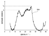
- FIG. 1A is a diagram showing the results of X-ray diffraction of the carbonized material obtained in Example 1, wherein the horizontal axis represents the diffraction angle 2 ⁇ (°) and the vertical axis represents the diffraction intensity (arbitrary unit).
- the horizontal axis represents the diffraction angle 2 ⁇ (°)
- the vertical axis represents the diffraction intensity (arbitrary unit).
- FIG. 2A is a diagram showing a peak spectrum 30A obtained from the X-ray diffraction pattern of FIG. 1A.
- the maximum intensity of a peak definitive range diffraction angle 2 ⁇ of 11.5 ⁇ 15.0 ° and I F, the maximum peak in the range of 18.0 ⁇ 26.5 ° strength was I G.
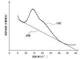
- FIG. 1B is a diagram showing the results of X-ray diffraction of Comparative Example 1.
- the X-ray diffraction pattern 10B obtained by the X-ray diffraction method has a downwardly convex portion with a diffraction angle 2 ⁇ in the range of 5.5 to 12.5 °, and 30.5.
- a straight line 20B in contact with both of the downward convex portions in a range of ⁇ 37 ° was drawn, and the straight line was used as the background 20B of the X-ray diffraction pattern 10B.
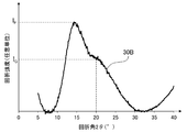
- a peak spectrum 30B was created by subtracting the value of the background 20B from the X-ray diffraction pattern 10B.
- the peak spectrum 30B since the peak of the I G had become shoulder, the diffraction intensity at a diffraction angle 20 ° was I G.
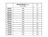
- FIG. 3 shows the results of evaluating the carbon catalysts obtained in Examples 1 to 7 and Comparative Examples 1 to 6 by the above-described method. That is, in FIG. 3, each of the embodiments, the carbon catalyst obtained in Comparative Example, the oxygen reduction onset potential of the carbon catalyst (E O2) (V (vs.RHE )), of the carbon catalyst I G / IF ratio (-) is shown.
- E O2 oxygen reduction onset potential of the carbon catalyst
- V vs.RHE
- the carbon catalysts according to Examples 1 to 7 have an I G / IF ratio in the range of 1.0 to 3.0, and the oxygen reduction starting potential (E O2 ) is 0.80 V ( vs. RHE) or higher.
- the carbon catalyst according to Comparative Example 1 is I G / I F ratio is as low as 0.6, the oxygen reduction onset potential (E O2) includes a 0.27V (Vs.RHE) It was lower than Examples 1-7.
- the I G / IF ratio is 0.5 to 0.00. 7
- the oxygen reduction starting potential (E O2 ) was also as low as 0.39 to 0.47 V (vs. RHE).
- carbon catalyst I G / I F ratio is 1.0 or more, compared to the case I G / I F ratio is less than 1.0, and had a high oxygen reduction activity.
- carbonized material according to Comparative Example 6 is an I G / I F ratio 12, an oxygen reduction onset potential (E O2) was 0.52V (vs.RHE). Furthermore, carbonized material according to Comparative Example 5 is an I G / I F ratio 18.9, oxygen reduction onset potential (E O2), the carbon of Comparative Example 6 and 0.49V (vs.RHE) It was even lower than the material. Thus, the carbonized material having an I G / IF ratio of 12 or more had a lower oxygen reduction initiation potential (E O2 ) than that when the I G / IF ratio was less than 12.
- the carbonized material according to Example 3 has an oxygen reduction start potential (E O2 ) of 0.83 V (vs. RHE), and the carbonized material according to Example 1 (oxygen reduction start potential of 0.84 V ( v. RHE)), it had high oxygen reduction activity.
- the carbonized material according to Example 3 is obtained by subjecting the carbonized material used in Example 1 to metal removal treatment. That is, the carbonized material according to Example 1 had high catalytic activity before and after metal removal. Thus, it was considered that the high catalytic activity of the carbonized material according to the example was contributed by the carbon structure represented by the above-mentioned I G / IF ratio.
- the I G / I F ratio was also obtained for the carbonized material produced in the same manner as in Example 1 except that carbon black (Vulcan: XC) was used instead of fullerene soot. I tried to evaluate, but the peak of the I F has not been confirmed.
Landscapes
- Chemical & Material Sciences (AREA)
- Engineering & Computer Science (AREA)
- Materials Engineering (AREA)
- Chemical Kinetics & Catalysis (AREA)
- Organic Chemistry (AREA)
- General Chemical & Material Sciences (AREA)
- Electrochemistry (AREA)
- Physics & Mathematics (AREA)
- Thermal Sciences (AREA)
- Carbon And Carbon Compounds (AREA)
- Catalysts (AREA)
- Fuel Cell (AREA)
- Inert Electrodes (AREA)
Applications Claiming Priority (2)
| Application Number | Priority Date | Filing Date | Title |
|---|---|---|---|
| JP2013249263A JP6189197B2 (ja) | 2013-12-02 | 2013-12-02 | 炭素触媒及びその製造方法並びにこれを用いた電極及び電池 |
| JP2013-249263 | 2013-12-02 |
Publications (1)
| Publication Number | Publication Date |
|---|---|
| WO2015083571A1 true WO2015083571A1 (ja) | 2015-06-11 |
Family
ID=53273336
Family Applications (1)
| Application Number | Title | Priority Date | Filing Date |
|---|---|---|---|
| PCT/JP2014/081010 Ceased WO2015083571A1 (ja) | 2013-12-02 | 2014-11-25 | 炭素触媒及びその製造方法並びにこれを用いた電極及び電池 |
Country Status (2)
| Country | Link |
|---|---|
| JP (1) | JP6189197B2 (enExample) |
| WO (1) | WO2015083571A1 (enExample) |
Cited By (2)
| Publication number | Priority date | Publication date | Assignee | Title |
|---|---|---|---|---|
| EP3570353A1 (fr) * | 2018-05-14 | 2019-11-20 | Commissariat à l'Energie Atomique et aux Energies Alternatives | Couches catalytiques comprenant un fullerene |
| CN113368899A (zh) * | 2021-07-03 | 2021-09-10 | 太原理工大学 | 一种高酸密度拟纤维素酶树脂固体酸催化剂的制备方法 |
Citations (3)
| Publication number | Priority date | Publication date | Assignee | Title |
|---|---|---|---|---|
| JP2010275140A (ja) * | 2009-05-27 | 2010-12-09 | Hokkaido Univ | 水素吸蔵炭素材料及びその製造方法 |
| JP2012200643A (ja) * | 2011-03-24 | 2012-10-22 | Nec Corp | 酸素還元触媒及びその製造方法 |
| JP2013111496A (ja) * | 2011-11-25 | 2013-06-10 | Gunma Univ | 金属担持用担体、金属担持触媒、メタネーション反応装置及びこれらに関する方法 |
-
2013
- 2013-12-02 JP JP2013249263A patent/JP6189197B2/ja active Active
-
2014
- 2014-11-25 WO PCT/JP2014/081010 patent/WO2015083571A1/ja not_active Ceased
Patent Citations (3)
| Publication number | Priority date | Publication date | Assignee | Title |
|---|---|---|---|---|
| JP2010275140A (ja) * | 2009-05-27 | 2010-12-09 | Hokkaido Univ | 水素吸蔵炭素材料及びその製造方法 |
| JP2012200643A (ja) * | 2011-03-24 | 2012-10-22 | Nec Corp | 酸素還元触媒及びその製造方法 |
| JP2013111496A (ja) * | 2011-11-25 | 2013-06-10 | Gunma Univ | 金属担持用担体、金属担持触媒、メタネーション反応装置及びこれらに関する方法 |
Non-Patent Citations (2)
| Title |
|---|
| JUN'ICHI OZAKI: "Preparation of cathode catalysts for PEMFC by carbon-alloying techniques", TANSO, vol. 2005, no. 218, 15 June 2005 (2005-06-15), pages 178 - 184 * |
| SHIGERU SHUTO ET AL.: "Fullerene Soot-kei Denkyoku no Denki Kagaku Yoryo to Nano Kozo tono Sokan", ABSTRACTS OF ANNUAL MEETING OF THE CARBON SOCIETY OF JAPAN, 7 December 2005 (2005-12-07), pages 324 - 325 * |
Cited By (2)
| Publication number | Priority date | Publication date | Assignee | Title |
|---|---|---|---|---|
| EP3570353A1 (fr) * | 2018-05-14 | 2019-11-20 | Commissariat à l'Energie Atomique et aux Energies Alternatives | Couches catalytiques comprenant un fullerene |
| CN113368899A (zh) * | 2021-07-03 | 2021-09-10 | 太原理工大学 | 一种高酸密度拟纤维素酶树脂固体酸催化剂的制备方法 |
Also Published As
| Publication number | Publication date |
|---|---|
| JP2015104717A (ja) | 2015-06-08 |
| JP6189197B2 (ja) | 2017-08-30 |
Similar Documents
| Publication | Publication Date | Title |
|---|---|---|
| JP4964292B2 (ja) | 電極及び電池 | |
| JP5149364B2 (ja) | 炭素触媒及びその製造方法並びにこれを用いた電極及び電池 | |
| JP5481646B2 (ja) | 炭素触媒、燃料電池、蓄電装置 | |
| JP6097456B2 (ja) | 炭素触媒、電極及び電池 | |
| US11014074B2 (en) | Cell electrode, composition for cell electrode catalyst layer, and cell | |
| Sharma et al. | Effects of structural disorder and nitrogen content on the oxygen reduction activity of polyvinylpyrrolidone-derived multi-doped carbon | |
| US12080896B2 (en) | Carbon catalyst, battery electrode, and battery | |
| JPWO2019013050A1 (ja) | 炭素触媒、電池電極及び電池 | |
| JP5689379B2 (ja) | 触媒担持用担体、触媒担持体、電極及び電池 | |
| JP6189197B2 (ja) | 炭素触媒及びその製造方法並びにこれを用いた電極及び電池 | |
| JP5732667B2 (ja) | 炭素触媒の製造方法 |
Legal Events
| Date | Code | Title | Description |
|---|---|---|---|
| 121 | Ep: the epo has been informed by wipo that ep was designated in this application |
Ref document number: 14868070 Country of ref document: EP Kind code of ref document: A1 |
|
| NENP | Non-entry into the national phase |
Ref country code: DE |
|
| 122 | Ep: pct application non-entry in european phase |
Ref document number: 14868070 Country of ref document: EP Kind code of ref document: A1 |