WO2015083449A1 - 電動機の制御装置および制御方法 - Google Patents
電動機の制御装置および制御方法 Download PDFInfo
- Publication number
- WO2015083449A1 WO2015083449A1 PCT/JP2014/077558 JP2014077558W WO2015083449A1 WO 2015083449 A1 WO2015083449 A1 WO 2015083449A1 JP 2014077558 W JP2014077558 W JP 2014077558W WO 2015083449 A1 WO2015083449 A1 WO 2015083449A1
- Authority
- WO
- WIPO (PCT)
- Prior art keywords
- control mode
- current
- voltage
- command value
- voltage phase
- Prior art date
- Legal status (The legal status is an assumption and is not a legal conclusion. Google has not performed a legal analysis and makes no representation as to the accuracy of the status listed.)
- Ceased
Links
Images


Classifications
-
- H—ELECTRICITY
- H02—GENERATION; CONVERSION OR DISTRIBUTION OF ELECTRIC POWER
- H02P—CONTROL OR REGULATION OF ELECTRIC MOTORS, ELECTRIC GENERATORS OR DYNAMO-ELECTRIC CONVERTERS; CONTROLLING TRANSFORMERS, REACTORS OR CHOKE COILS
- H02P27/00—Arrangements or methods for the control of AC motors characterised by the kind of supply voltage
- H02P27/04—Arrangements or methods for the control of AC motors characterised by the kind of supply voltage using variable-frequency supply voltage, e.g. inverter or converter supply voltage
- H02P27/06—Arrangements or methods for the control of AC motors characterised by the kind of supply voltage using variable-frequency supply voltage, e.g. inverter or converter supply voltage using DC to AC converters or inverters
-
- H—ELECTRICITY
- H02—GENERATION; CONVERSION OR DISTRIBUTION OF ELECTRIC POWER
- H02P—CONTROL OR REGULATION OF ELECTRIC MOTORS, ELECTRIC GENERATORS OR DYNAMO-ELECTRIC CONVERTERS; CONTROLLING TRANSFORMERS, REACTORS OR CHOKE COILS
- H02P21/00—Arrangements or methods for the control of electric machines by vector control, e.g. by control of field orientation
- H02P21/14—Estimation or adaptation of machine parameters, e.g. flux, current or voltage
- H02P21/20—Estimation of torque
-
- H—ELECTRICITY
- H02—GENERATION; CONVERSION OR DISTRIBUTION OF ELECTRIC POWER
- H02P—CONTROL OR REGULATION OF ELECTRIC MOTORS, ELECTRIC GENERATORS OR DYNAMO-ELECTRIC CONVERTERS; CONTROLLING TRANSFORMERS, REACTORS OR CHOKE COILS
- H02P21/00—Arrangements or methods for the control of electric machines by vector control, e.g. by control of field orientation
- H02P21/22—Current control, e.g. using a current control loop
-
- H—ELECTRICITY
- H02—GENERATION; CONVERSION OR DISTRIBUTION OF ELECTRIC POWER
- H02P—CONTROL OR REGULATION OF ELECTRIC MOTORS, ELECTRIC GENERATORS OR DYNAMO-ELECTRIC CONVERTERS; CONTROLLING TRANSFORMERS, REACTORS OR CHOKE COILS
- H02P6/00—Arrangements for controlling synchronous motors or other dynamo-electric motors using electronic commutation dependent on the rotor position; Electronic commutators therefor
- H02P6/10—Arrangements for controlling torque ripple, e.g. providing reduced torque ripple
Definitions
- the present invention relates to a motor control device and control method.
- An object of the present invention is to provide a technique for suppressing the generation of a torque step when switching from voltage phase control to current control.
- the motor control device generates a current command value to the motor based on a motor constant and a torque command value corresponding to a predetermined temperature, and sets an applied voltage to the motor so as to follow the current command value.
- the current control mode for controlling the current control mode and the motor constant corresponding to the predetermined temperature are used to calculate the estimated torque value of the motor.
- the voltage phase Based on the voltage phase control means for executing the voltage phase control mode for feedback operation and the magnitude relationship between the current command value and the detected current in the current control mode, the switching from the voltage phase control mode to the current control mode is determined.
- the voltage amplitude command value in the voltage phase control mode is larger than the voltage amplitude realized in the current control mode in the application region of the voltage phase control mode, and the voltage realized in the current control mode in the application region of the current control mode. It is set to be less than the amplitude.
- FIG. 1 is a block diagram illustrating a configuration of an electric motor control device according to an embodiment.
- FIG. 2 is a block diagram illustrating processing performed inside the current control transition determination unit.
- FIG. 3 is a diagram that defines the relationship between the rotational speed N of the motor and the voltage amplitude command value V a * in the voltage phase control mode.
- FIG. 4 is a diagram for explaining the behavior when the switching mode is switched by the conventional control device described in JP3683135B.
- FIG. 5 is a diagram for explaining the behavior when the switching mode is switched by the motor control device according to the embodiment.
- FIG. 6 is a flowchart showing control contents in the voltage phase control mode and the current control mode.
- FIG. 7 is a diagram illustrating an example of a control result by the motor control device according to the embodiment.
- FIG. 8 is a diagram for explaining a situation where the control mode is forcibly switched to the current control mode when the control mode is not switched from the voltage phase control mode to the current control mode even if the motor rotation speed is reduced to a predetermined rotation speed. is there.
- FIG. 1 is a block diagram illustrating a configuration of a motor control device according to an embodiment.
- This motor control device is applied to, for example, an electric vehicle.
- the present invention can be applied to a hybrid vehicle or a system other than a vehicle.
- the current command generator 1 determines the relationship between the torque command value T * , the DC voltage V dc of the battery 7, and the rotation speed N (hereinafter referred to as motor rotation speed) N of the motor 9, and the d-axis current and the q-axis current.
- the determined table is stored, and the torque command value T * , the DC voltage V dc of the battery 7 and the motor rotation speed N are input, and the d-axis current command value i d * and The q-axis current command value i q * is obtained.
- the d-axis current and the q-axis current defined in the table are a d-axis current and a q-axis current that obtain a desired torque when the motor temperature is 25 ° C. obtained in advance by experiment or analysis.
- the current command values i d * and i q * are current command values in the current control mode.
- the interference voltage generation unit 2 stores a table that defines the relationship between the torque command value T * , the DC voltage V dc of the battery 7, the motor rotation speed N, and the d-axis and q-axis interference voltages.
- the command value T * , the DC voltage V dc of the battery 7 and the motor rotational speed N are input, and the d-axis interference voltage V d_dcpl * and the q-axis interference voltage V q _dcpl * are obtained by referring to the above table.
- the current vector controller 3 includes a d-axis current command value i d * and a q-axis current command value i q * , a d-axis current detection value i d and a q-axis current command value i q, and a d-axis interference voltage V d_dcpl *. Based on the q-axis interference voltage V q_dcpl * , vector current control by known non-interference control and current feedback control is performed to calculate the d-axis voltage command value V di * and the q-axis voltage command value V qi * .
- the voltage command values V di * and V qi * are voltage command values in the current control mode.
- the voltage amplitude generation unit 13 obtains a voltage amplitude command value V a * in the voltage phase control mode by a method described later.
- Torque calculator 15 the magnet flux ⁇ a_25 °C in motor temperature 25 ° C. which is previously stored, the inductance difference of the d-axis and q-axis in the motor temperature 25 °C (L d -L q) 25 °C, and, d-axis current
- the command value i d * and the q-axis current command value i q * are input, and the estimated torque value T cal of the electric motor 9 is calculated by the following equation (1).
- Equation (1) p is the number of pole pairs of the electric motor 9.
- the inductance difference between the d-axis and the q-axis (L d ⁇ L q ) 25 ° C. at the motor temperature of 25 ° C. is obtained by the inductance generator 14.
- the torque controller 16 inputs a difference between the torque command value T * and the estimated torque value T cal and calculates a value obtained by PI amplification by the following equation (2) as a voltage phase command value ⁇ * .
- a K p is a proportional gain in formula (2)
- K i is an integral gain.
- the dq-axis voltage generation unit 17 inputs the voltage amplitude command value V a * obtained by the voltage amplitude generation unit 13 and the voltage phase command value ⁇ * calculated by the torque controller 16, and the following equation (3)
- the d-axis voltage command value V dv * and the q-axis voltage command value V qv * are calculated.
- the voltage command values V dv * and V qv * are voltage command values in the voltage phase control mode.
- the current control transition determination unit 20 includes a d-axis current command value i d * and a q-axis current command value i q * obtained by the current command generation unit 1, and a d-axis current detection value i d and a q-axis current command value i q. And whether or not to shift from the voltage phase control mode to the current control mode is determined based on the magnitude relationship between the current command value and the detected current in the current control mode.
- FIG. 2 is a block diagram illustrating processing performed inside the current control transition determination unit 20.
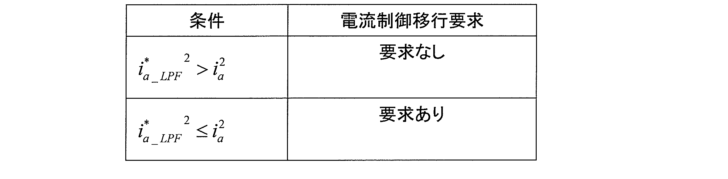
- the d-axis current command value i d * and the q-axis current command value i q * are subjected to filter processing corresponding to the normative response by the norm response filter 21 in consideration of the transient state, By obtaining the sum of squares, ia_LPF 2 is calculated. Further, by calculating the sum of squares of the detected d-axis current value i d and the q-axis current command value i q , i a 2 is calculated. Then, as shown in Table 1, if i a_LPF 2 is larger than i a 2 , it is determined that the voltage phase control mode does not shift to the current control mode. If i a_LPF 2 is equal to or less than i a 2 , the voltage phase control mode is determined. Is determined to shift to the current control mode, and a control mode switching request is output.
- the voltage phase control transition determination unit 19 performs transition determination from the current control mode to the voltage phase control mode.
- the threshold value T ref set on the high rotation high torque side from the range where the switching from the voltage phase control mode to the current control mode occurs is stored in advance as a table using the motor rotation speed and the DC voltage of the battery 7 as an index,
- the torque command value T * is equal to or greater than the threshold value T ref obtained by referring to the table, it is determined that the current control mode is shifted to the voltage phase control mode, and a control mode switching request is output.
- control mode determination unit 21 When the control mode switching request is output from the current control transition determination unit 20 or the voltage phase control transition determination unit 19, the control mode determination unit 21 outputs the control mode after switching to the control mode switch 18.
- the control mode switch 18 is input from the control mode determination unit 21 among the voltage command values V di * and V qi * based on the current control mode and the voltage command values V dv * and V qv * based on the voltage phase control mode.
- a voltage command value corresponding to the control mode is selected and output to the dq axis / UVW phase converter 4 as the d axis voltage command value V d * and the q axis voltage command value V q * .
- the dq-axis / UVW phase converter 4 calculates the d-axis voltage command value V d * and the q-axis voltage command value V q * based on the electrical angle ⁇ of the rotor detected by the position detector 10 according to the following formula ( 4) is converted into three-phase voltage command values Vu *, Vv *, and Vw *.
- the PWM converter 5 performs dead time compensation and voltage utilization rate improvement processing (both are publicly known), and power element drive signals of the inverter 6 corresponding to the three-phase voltage command values V u * , V v * , V w *. D uu * , D ul * , D vu * , D vl * , D wu * and D wl * are generated.
- a battery 7 is connected to the inverter 6, and the battery voltage V dc is detected by a DC voltage sensor.
- the inverter 6 converts the DC voltage of the battery 7 from the pseudo AC voltages V u , V v , V wl * , D wl * , D vl * , D wu * , D wl * based on the power element driving signals D uu * , D ul * , D vu * , D vl * , D wl * . Convert to V w and output.
- the pseudo-alternating voltages V u , V v and V w converted by the inverter 6 are applied to the electric motor 9.
- Current sensor 8 of the current flowing through each phase of the motor 9, any two-phase current, for example, detects the U-phase current i u and the V-phase current i v.
- the remaining one-phase current that is not detected, for example, the W-phase current i w can be calculated based on the following equation (5).
- the UVW phase / dq axis converter 12 is based on i u , i v detected by the current sensor 8 based on the electrical angle ⁇ of the rotor of the electric motor 9 detected by the position detector 10, and Equation (5).
- the calculated i w is converted into a d-axis current i d and a q-axis current i q based on the following equation (6).
- the rotation speed calculator 11 calculates the rotation speed N of the electric motor 9 from the amount of change per hour of the electrical angle ⁇ detected by the position detector 10.
- FIG. 3 is a diagram defining the relationship between the rotational speed N of the electric motor 9 and the voltage amplitude command value V a * in the voltage phase control mode.
- the voltage amplitude Va at the lowest temperature and the voltage amplitude Va at the highest temperature in the operation guarantee range of the electric motor 9 are shown together with the voltage amplitude Va in the current control mode at the reference temperature (25 ° C.).
- the control in the current control mode is performed in the low rotation region, and the control in the voltage phase control mode is performed in the high rotation region where the flux weakening control is performed.
- the voltage amplitude Va increases as the motor rotation speed increases, and the voltage amplitude Va reaches the upper limit when the rotation speed exceeds a certain rotation speed.
- the rate of increase of the voltage amplitude Va with respect to the increase in the motor rotation speed varies depending on the temperature of the electric motor 9, and the upper limit value of the voltage amplitude Va also varies depending on the temperature of the electric motor 9. Specifically, when the temperature is lower than the reference temperature, the increasing rate of the voltage amplitude Va is larger than the increasing rate of the voltage amplitude Va at the reference temperature, and the upper limit value of the voltage amplitude is the upper limit of the voltage amplitude at the reference temperature. Greater than the value.
- the rate of increase of the voltage amplitude Va is smaller than the rate of increase of the voltage amplitude Va at the reference temperature, and the upper limit value of the voltage amplitude is higher than the upper limit value of the voltage amplitude at the reference temperature. small.
- FIG. 4 is a diagram for explaining the behavior when the switching mode is switched by the conventional control device described in JP3683135B.
- the control mode is switched from the voltage phase control mode to the current control mode when the phase of the detected current reaches a phase where the torque / current ratio becomes maximum.
- the voltage amplitude Va in the current control mode changes due to a temperature change or manufacturing variation of the electric motor 9.
- the voltage amplitude Va does not change sharply when the control mode is switched. That is, when there is no temperature change or manufacturing variation of the electric motor 9, when the motor rotation speed decreases from the high rotation side, the voltage phase control mode is switched to the current control mode at the point P1, so the control mode is switched.
- the voltage amplitude Va does not change sharply.
- the voltage phase control mode is switched from the voltage phase control mode to the current control mode at the point P2, so that the voltage amplitudes before and after switching of the control mode do not match.
- the voltage amplitude Va changes abruptly.
- the temperature of the electric motor 9 is higher than the reference temperature (25 ° C.)
- the voltage amplitude Va changes sharply because the voltage phase control mode is switched to the current control mode at the point P3.
- FIG. 5 is a diagram for explaining the behavior when the switching mode is switched by the motor control device according to the embodiment.
- the motor control apparatus even when there is a temperature change or manufacturing variation of the motor 9, if the motor rotation speed decreases, the voltage amplitude command value V a * in the voltage phase control mode and the current There is a point where the voltage amplitude Va in the control mode matches.
- the feedback control configuration allows torque fluctuation due to magnetic flux change.
- the motor control device determines the transition from the voltage phase control mode to the current control mode based on the current amplitude value.
- the voltage phase control mode is switched to the current control mode at point P4, and the control is performed.
- the voltage amplitude Va does not change abruptly when the mode is switched.
- the voltage phase control mode is switched to the current control mode at the point P5.
- the voltage phase control is performed at the point P6. Switch from mode to current control mode. As shown in FIG. 5, even when the temperature of the electric motor 9 changes, a sharp change in voltage amplitude does not occur when switching from the voltage phase control mode to the current control mode.
- FIG. 6 is a flowchart showing the control contents in the voltage phase control mode and the current control mode. If the current control mode is the voltage phase control mode, the process of step S10 is started. If the current control mode is the current control mode, the process of step S100 is started.
- step S10 torque command value T * , d-axis current command value i d * and q-axis current command value i q * , d-axis current detection value i d and q-axis current command value i q , rotor electrical angle ⁇
- the motor rotation speed N and the DC voltage V dc of the battery 7 are acquired.
- step S20 i a 2 and i a_LPF 2 are calculated (see FIG. 2).
- step S30 i a 2 calculated in step S20 is equal to or i a_LPF 2 or more. If it is determined that i a 2 is greater than or equal to i a_LPF 2 , the process proceeds to step S130 in order to switch the control mode from the voltage phase control mode to the current control mode. If it is determined that i a 2 is less than i a_LPF 2 , the process proceeds to step S40 in order to continue the processing in the voltage phase control mode.
- step S40 the voltage amplitude command value V a * is calculated by the voltage amplitude generator 13, and the inductance difference between the d-axis and the q-axis (L d ⁇ L q ) 25 ° C. is obtained by the inductance generator.
- step S50 the torque calculator 15 calculates the estimated torque value T cal of the electric motor 9 from the equation (1).
- step S60 the torque controller 16 calculates the voltage phase command value ⁇ * from the equation (2) based on the difference between the torque command value T * and the estimated torque Tcal .
- step S70 the dq-axis voltage generation unit 17 calculates the d-axis voltage command value V dv * and the q-axis voltage command value from Equation (3) based on the voltage amplitude command value V a * and the voltage phase command value ⁇ *.
- V qv * is calculated.
- the control mode switch 18 converts the d-axis voltage command value V dv * and the q-axis voltage command value V qv * into the d-axis voltage command value V d * and the q-axis voltage command value V q * , and a dq-axis / UVW phase converter. 4 is output.
- step S80 the dq-axis / UVW phase converter 4 converts the d-axis voltage command value V d * and the q-axis voltage command value V q * into the three-phase voltage command values V u * , V v from equation (4). * , Converted to V w * .
- step S100 the torque command value T * , the d-axis current detection value i d and the q-axis current command value i q , the rotor electrical angle ⁇ , the motor rotation speed N, and the DC voltage V dc of the battery 7 are acquired.
- step S110 the voltage phase control transition determination unit 19 obtains a threshold value T ref .
- step S120 it is determined whether or not the torque command value T * is greater than or equal to a threshold value Tref . If it is determined that the torque command value T * is equal to or greater than the threshold value T ref , the process proceeds to step S40 to shift the control mode from the current control mode to the voltage phase control mode. If it is determined that the torque command value T * is less than the threshold value T ref , the process proceeds to step S130 in order to continue the current control mode process.
- step S130 the current command generator 1 determines the d-axis current command value i d * and the q-axis current command value i q * .
- step S140 the current vector controller 3 calculates the d-axis voltage command value V di * and the q-axis voltage command value V qi * .
- the control mode switching unit 18 converts the d-axis voltage command value V di * and the q-axis voltage command value V qi * into the d-axis voltage command value V d * and the q-axis voltage command value V q * as a dq-axis / UVW phase converter. 4 is output.
- step S150 the dq-axis / UVW phase converter 4 converts the d-axis voltage command value V d * and the q-axis voltage command value V q * into the three-phase voltage command values V u * , V v according to equation (4). * , Converted to V w * .
- FIG. 7 is a diagram illustrating an example of a control result by the motor control device according to the embodiment.
- FIG. 7 shows control mode switching timing, voltage amplitude Va, and current amplitude Ia over time when the motor rotation speed increases and decreases while the torque command value remains constant.
- the current control mode is applied.
- the voltage amplitude Va also increases.
- the negative d-axis current is increased and field weakening control is performed, so that the current amplitude Ia increases and the increase in the voltage amplitude Va is suppressed.
- the torque command value T * becomes equal to or greater than the threshold value Tref , and the control mode is switched from the current control mode to the voltage phase control mode.
- the mode is switched to the voltage phase control mode, the voltage amplitude Va is increased, so that the weakening current is decreased and the current amplitude Ia is decreased.
- the voltage amplitude command value V a * is decreased and the current amplitude decrease rate is suppressed.
- the amplitude of the command value approaches the amplitude of the current command value in current control.
- the torque of the electric motor 9 is the product of the magnetic flux vector and the current vector, when the magnet temperature of the electric motor 9 changes, the torque changes due to the change of the magnetic flux.
- the current is controlled to be constant, but in the voltage phase control, since the current is not controlled, the current is also changed. Therefore, the voltage phase control mode and the current control mode have different torque sensitivities with respect to changes in the motor temperature.
- the torque is estimated based on the same temperature condition as the precondition for generating the current command value in the current control mode, and the voltage phase is fed back, so that the sensitivity of the torque to the temperature change of the motor is achieved. Can be made equivalent to those in the current control mode, and the steady torque between the control modes can be made to coincide.
- the voltage amplitude command value in the voltage phase control mode is set so that the voltage amplitude intersects in the current control mode and the voltage phase control mode, and the current command value amplitude in the current control mode and the voltage phase control mode are detected.
- the voltage phase control mode is switched to the current control mode at the timing when the amplitude of the current that has been crossed.
- the motor torque, d-axis voltage and q-axis voltage, d-axis current and q-axis current can all be switched without any step, and torque steps and shocks associated with switching the control mode can be suppressed. it can.
- the control mode changes from the voltage phase control mode to the current. If the control mode is not switched, the control for forcibly switching to the current control mode is also performed.
- FIG. 8 is a diagram for explaining a situation where the control mode is forcibly switched to the current control mode when the control mode is not switched from the voltage phase control mode to the current control mode even if the motor rotation speed is reduced to a predetermined rotation speed. is there.
- a line 81 indicates the voltage amplitude in the current control mode when the temperature of the electric motor 9 becomes a high temperature exceeding the guaranteed operating range.
- the current control mode is forcibly set. Switch to. If the temperature and manufacturing variation of the electric motor 9 are within the operation guarantee range, the predetermined rotation number is set in advance to an appropriate value based on the motor rotation number at which the voltage phase control mode is switched to the current control mode.
- the motor control device generates a current command value to the motor 9 based on the motor constant and the torque command value corresponding to the predetermined temperature, and supplies the current to the motor 9 so as to follow the current command value.
- a torque estimation value of the motor 9 is calculated by using current control means (current command generator 1, current vector controller 3) for executing a current control mode for controlling the applied voltage, and a motor constant corresponding to a predetermined temperature.
- voltage phase control means (a torque calculator 15, a torque controller 16, a dq axis voltage generator 17) that executes a voltage phase control mode in which the voltage phase is feedback-operated.
- a determination method for determining switching from the voltage phase control mode to the current control mode based on the magnitude relationship between the current command value and the detected current in the current control mode.
- control transition determination unit 20 Current control transition determination unit 20
- control mode switching means control mode determination unit 21, control mode switch 18 for switching between current control mode control and voltage phase control mode control based on the determination result by the determination unit.
- the voltage amplitude command value in the voltage phase control mode is larger than the voltage amplitude realized in the current control mode in the application region of the voltage phase control mode, and the voltage realized in the current control mode in the application region of the current control mode. It is set to be less than the amplitude.
- the voltage phase control mode is switched to the current control mode.
- the torque is estimated based on the same temperature condition as the precondition for generating the current command value in the current control mode, and the voltage phase is fed back, so that before and after the control mode switching. Therefore, the torque and current amplitude and phase, and the voltage amplitude and phase do not change before and after the control mode switching, and torque steps and shocks can be suppressed.
- the motor control device in the motor control device according to the embodiment, if the determination to switch from the voltage phase control mode to the current control mode is not performed even when the rotation speed of the motor 9 is equal to or lower than the predetermined rotation speed, Thus, the voltage phase control mode is switched to the current control mode. As a result, it is possible to prevent a decrease in control accuracy that occurs when the voltage phase control mode is continued, and a mechanical resonance that does not cause a problem in the current control mode.
- the present invention is not limited to the above-described embodiment, and various modifications and applications are possible.
- the motor constant at 25 ° C. as the motor constant corresponding to the predetermined temperature
- the example has been described, but the predetermined temperature is not limited to 25 ° C.
Landscapes
- Engineering & Computer Science (AREA)
- Power Engineering (AREA)
- Control Of Ac Motors In General (AREA)
Abstract
電動機の制御装置は、所定温度に対応した電動機定数およびトルク指令値に基づいて電動機への電流指令値を生成し、電流指令値に追従するように電動機への印加電圧を制御する電流制御モードを実行する機能と、所定温度に対応した電動機定数を用いて電動機のトルク推定値を算出し、算出したトルク推定値とトルク指令値との偏差に基づいて、電圧位相をフィードバック操作する電圧位相制御モードを実行する機能とを有する。電動機の制御装置はまた、電流制御モードにおける電流指令値と検出電流との間の大小関係に基づいて、制御モードの切替を判定して、制御モードを切り替える。電圧位相制御モード時の電圧振幅指令値は、電圧位相制御モードの適用領域では、電流制御モード時の電圧振幅よりも大きく、電流制御モードの適用領域では、電流制御モード時の電圧振幅以下である。
Description
本発明は、電動機の制御装置および制御方法に関する。
従来、電圧位相制御とPWM電流制御とを選択的に用いて交流電動機を制御する制御装置が知られている。JP3683135Bに記載された制御装置では、電圧位相制御中に、電流検出器で検出された電流の位相がトルク/電流比が最大となる位相に達すると、PWM電流制御に切り替えることが開示されている。
しかしながら、JP3683135Bに開示された技術では、電動機の温度変化や電動機の製造バラツキがある場合、電圧位相制御からPWM電流制御に切り替える際の切替前後で電流位相が一致していても、電流振幅や電圧振幅が一致せず、制御の切替時にトルク段差が発生する可能性がある。
本発明は、電圧位相制御から電流制御に切り替える際のトルク段差の発生を抑制する技術を提供することを目的とする。
本発明の一態様における電動機の制御装置は、所定温度に対応した電動機定数およびトルク指令値に基づいて電動機への電流指令値を生成し、電流指令値に追従するように電動機への印加電圧を制御する電流制御モードを実行する電流制御手段と、所定温度に対応した電動機定数を用いて電動機のトルク推定値を算出し、算出したトルク推定値とトルク指令値との偏差に基づいて、電圧位相をフィードバック操作する電圧位相制御モードを実行する電圧位相制御手段と、電流制御モードにおける電流指令値と検出電流との間の大小関係に基づいて、電圧位相制御モードから電流制御モードへの切替を判定する判定手段と、判定手段による判定結果に基づいて、電流制御手段による制御か電圧位相制御手段による制御かを切り替える制御モード切替手段とを備える。電圧位相制御モード時の電圧振幅指令値は、電圧位相制御モードの適用領域では、電流制御モード時に実現される電圧振幅よりも大きく、電流制御モードの適用領域では、電流制御モード時に実現される電圧振幅以下となるように設定されている。
本発明の実施形態については、添付された図面とともに以下に詳細に説明する。
図1は、一実施の形態における電動機の制御装置の構成を示すブロック図である。この電動機の制御装置は、例えば、電気自動車に適用される。なお、電気自動車以外に、例えば、ハイブリッド自動車や、自動車以外のシステムに適用することも可能である。
電流指令生成部1は、トルク指令値T*、バッテリ7の直流電圧Vdc、および電動機9の回転数(以下、モータ回転数と呼ぶ)Nと、d軸電流およびq軸電流との関係を定めたテーブルを格納しており、トルク指令値T*、バッテリ7の直流電圧Vdc、およびモータ回転数Nを入力して、上記テーブルを参照することにより、d軸電流指令値id
*およびq軸電流指令値iq
*を求める。テーブルで規定されているd軸電流およびq軸電流は、予め実験または解析により求めた電動機温度25℃の場合に所望のトルクを得るd軸電流およびq軸電流である。この電流指令値id
*、iq
*は、電流制御モードにおける電流指令値である。
なお、電流指令値を生成する方法は種々のものが提案されており、例えば、下記の参考文献に記載されている効率最大法を用いて、25℃の場合のモータ定数を用いて計算的に求めることも可能である。
参考文献:「実用モータドライブ制御系設計とその実際」第7章第4項、内藤治夫著、日本テクノセンター発行
参考文献:「実用モータドライブ制御系設計とその実際」第7章第4項、内藤治夫著、日本テクノセンター発行
干渉電圧生成部2は、トルク指令値T*、バッテリ7の直流電圧Vdc、およびモータ回転数Nと、d軸およびq軸の干渉電圧との関係を定めたテーブルを格納しており、トルク指令値T*、バッテリ7の直流電圧Vdc、およびモータ回転数Nを入力して、上記テーブルを参照することにより、d軸干渉電圧Vd_dcpl
*およびq軸干渉電圧V q_dcpl
*を求める。
電流ベクトル制御器3は、d軸電流指令値id
*およびq軸電流指令値iq
*と、d軸電流検出値idおよびq軸電流指令値iqと、d軸干渉電圧Vd_dcpl
*およびq軸干渉電圧Vq_dcpl
*に基づいて、公知の非干渉制御と電流フィードバック制御によるベクトル電流制御を行い、d軸電圧指令値Vdi
*およびq軸電圧指令値Vqi
*を算出する。この電圧指令値Vdi
*、Vqi
*は、電流制御モードにおける電圧指令値である。
電圧振幅生成部13は、後述する方法により、電圧位相制御モードにおける電圧振幅指令値Va
*を求める。
トルク演算器15は、予め記憶されている電動機温度25℃における磁石磁束φa_25℃、電動機温度25℃におけるd軸およびq軸のインダクタンス差(Ld-Lq)25℃、および、d軸電流指令値id
*およびq軸電流指令値iq
*を入力し、次式(1)により電動機9のトルク推定値Tcalを算出する。

なお、式(1)において、pは電動機9の極対数である。また、電動機温度25℃におけるd軸およびq軸のインダクタンス差(Ld-Lq)25℃は、インダクタンス生成部14により求められる。具体的には、予めオフラインで解析または実験を行って、トルク指令値T*、バッテリ7の直流電圧Vdc、およびモータ回転数Nと、d軸およびq軸のインダクタンス差(Ld-Lq)25℃との関係を定めたテーブルを用意しておき、トルク指令値T*、バッテリ7の直流電圧Vdc、およびモータ回転数Nを入力して、上記テーブルを参照することにより、d軸およびq軸のインダクタンス差(Ld-Lq)25℃を求める。
トルク制御器16は、トルク指令値T*とトルク推定値Tcalの差分を入力し、次式(2)によりPI増幅した値を、電圧位相指令値α*として算出する。ただし、式(2)中のKpは比例ゲインであり、Kiは積分ゲインである。

dq軸電圧生成部17は、電圧振幅生成部13によって求められる電圧振幅指令値Va
*と、トルク制御器16によって算出される電圧位相指令値α*とを入力し、次式(3)により、d軸電圧指令値Vdv
*およびq軸電圧指令値Vqv
*を算出する。この電圧指令値Vdv
*、Vqv
*は、電圧位相制御モードにおける電圧指令値である。

電流制御移行判定部20は、電流指令生成部1によって求められるd軸電流指令値id
*およびq軸電流指令値iq
*と、d軸電流検出値idおよびq軸電流指令値iqとを入力し、電流制御モードにおける電流指令値と検出電流との間の大小関係に基づいて、電圧位相制御モードから電流制御モードへ移行するか否かの判定を行う。
図2は、電流制御移行判定部20の内部で行われる処理を示すブロック図である。d軸電流指令値id
*およびq軸電流指令値iq
*は、規範応答フィルタ21により、過渡状態を考慮して規範応答に相当するフィルタ処理が施され、フィルタ処理後の値に対して自乗和を求めることにより、ia_LPF
2が算出される。また、d軸電流検出値idおよびq軸電流指令値iqの自乗和を求めることにより、ia
2を算出する。そして、表1のように、ia_LPF
2がia
2より大きければ、電圧位相制御モードから電流制御モードへ移行しないと判定し、ia_LPF
2がia
2以下であれば、電圧位相制御モードから電流制御モードへ移行すると判定して、制御モードの切替要求を出力する。
電圧位相制御移行判定部19は、電流制御モードから電圧位相制御モードへの移行判定を行う。電圧位相制御モードから電流制御モードへの切替が起こる範囲よりも高回転高トルク側に設定した閾値Trefを、予めモータ回転数とバッテリ7の直流電圧を指標としたテーブルとして格納しており、トルク指令値T*がテーブルを参照して求めた閾値Tref以上の場合に、電流制御モードから電圧位相制御モードへ移行すると判定して、制御モードの切替要求を出力する。
制御モード判定部21は、電流制御移行判定部20または電圧位相制御移行判定部19から制御モードの切替要求が出力されると、切替後の制御モードを制御モード切替器18に出力する。
制御モード切替器18は、電流制御モードによる電圧指令値Vdi
*、Vqi
*と、電圧位相制御モードによる電圧指令値Vdv
*、Vqv
*のうち、制御モード判定部21から入力される制御モードに応じた電圧指令値を選択して、d軸電圧指令値Vd
*およびq軸電圧指令値Vq
*としてdq軸/UVW相変換器4に出力する。
dq軸/UVW相変換器4は、位置検出器10によって検出された回転子の電気角θに基づいて、d軸電圧指令値Vd
*およびq軸電圧指令値Vq
*を、次式(4)により三相電圧指令値Vu*、Vv*、Vw*に変換する。

PWM変換器5は、デッドタイム補償や電圧利用率向上処理(いずれも公知)を行うとともに、三相電圧指令値Vu
*、Vv
*、Vw
*に対応したインバータ6のパワー素子駆動信号Duu*、Dul*、Dvu*、Dvl*、Dwu*、Dwl*を生成する。
インバータ6には、バッテリ7が接続されており、バッテリ電圧Vdcは、直流電圧センサにより検出される。インバータ6は、パワー素子駆動信号Duu*、Dul*、Dvu*、Dvl*、Dwu*、Dwl*に基づいて、バッテリ7の直流電圧を疑似交流電圧Vu、Vv、Vwに変換して出力する。
電動機9には、インバータ6により変換された疑似交流電圧Vu、Vv、Vwが印加される。電流センサ8は、電動機9の各相に流れる電流のうち、任意の2相の電流、例えば、U相電流iuおよびV相電流ivを検出する。検出されない残りの1相の電流、例えば、W相電流iwは、次式(5)に基づいて算出することができる。

UVW相/dq軸変換器12は、位置検出器10で検出された電動機9の回転子の電気角θに基づいて、電流センサ8で検出されたiu、iv、および式(5)により算出されたiwを、次式(6)に基づいて、d軸電流idおよびq軸電流iqに変換する。

回転数演算器11は、位置検出器10で検出された電気角θの時間当たりの変化量から、電動機9の回転数Nを算出する。
電圧振幅生成部13が電圧振幅指令値Va
*を求める方法について説明する。
図3は、電動機9の回転数Nと、電圧位相制御モードにおける電圧振幅指令値Va
*との関係を定めた図である。図3では、基準温度(25℃)での電流制御モードにおける電圧振幅Vaとともに、電動機9の動作保証範囲内における最低温度での電圧振幅Vaおよび最高温度での電圧振幅Vaも示している。電流制御モードによる制御は、低回転領域で行われ、電圧位相制御モードによる制御は、弱め磁束制御を行うような高回転領域で行われる。
図3に示すように、電流制御モードでは、モータ回転数が高くなると、電圧振幅Vaも大きくなり、ある回転数以上になると、電圧振幅Vaは上限値に達する。モータ回転数の上昇に対する電圧振幅Vaの上昇率は、電動機9の温度により異なり、また、電圧振幅Vaの上限値も電動機9の温度により異なる。具体的には、基準温度よりも温度が低い場合には、電圧振幅Vaの上昇率が基準温度における電圧振幅Vaの上昇率よりも大きく、電圧振幅の上限値は、基準温度における電圧振幅の上限値よりも大きい。また、基準温度よりも温度が高い場合には、電圧振幅Vaの上昇率が基準温度における電圧振幅Vaの上昇率よりも小さく、電圧振幅の上限値は、基準温度における電圧振幅の上限値よりも小さい。
電圧位相制御モードが適用されるモータ回転領域では、電動機9の温度変化や製造バラツキによって電流制御モードによる電圧振幅Vaが変動しても、必ず電圧振幅Vaより大きい値となるように電圧振幅指令値Va
*を設定する。また、電流制御モードが適用されるモータ回転領域では、電動機9の温度変化や製造バラツキによって電流制御モードによる電圧振幅Vaが変動しても、必ず電圧振幅Va以下となるように電圧振幅指令値Va
*を設定する。
図3を参照しながら説明すると、電流制御モードでは基準温度における電圧振幅Vaが上限に達するような動作領域aにおいては、電圧振幅Vaの上限値を超える電圧振幅指令値Va
*を生成し、領域aよりもモータ回転数が低い領域bでは、電流制御モードで実現される電圧振幅Vaを下回る電圧振幅指令値Va
*を生成する。領域bでは、電流制御モードにおける電圧振幅Vaが電動機9の温度変化や製造バラツキによって変化したとしても、電圧振幅Vaが電圧振幅指令値Va
*を下回らないように、電圧振幅指令値Va
*を設定しておく。このように、電圧振幅が必ず制御モード間で反転するように電圧振幅指令値Va
*を設定しておくことにより、制御モード間で電流の大きさも反転するようになる。
上述したルールに従って、実験または解析を行い、トルク指令値、モータ回転数、およびバッテリ7の直流電圧と、電圧振幅指令値Va
*との関係を定めたテーブルを予め用意しておき、トルク指令値T*、モータ回転数N、およびバッテリ7の直流電圧Vdcに基づいて、上記テーブルを参照することにより、電圧振幅指令値Va
*を求める。
なお、電流制御モードにおける電流指令値から、温度変化や電動機9の製造バラツキを考慮して実現される最小電圧振幅を演算して求めることも可能である。
図4は、JP3683135Bに記載の従来の制御装置による切替モード切替時の挙動を説明するための図である。従来の制御装置では、検出電流の位相が、トルク/電流比が最大となる位相に達した時に制御モードを電圧位相制御モードから電流制御モードに切り替えている。
上述したように、電流制御モードにおける電圧振幅Vaは、電動機9の温度変化や製造バラツキによって変化する。電動機9の温度変化や製造バラツキが存在しない場合には、制御モードの切替時に電圧振幅Vaが急峻に変化することはない。すなわち、電動機9の温度変化や製造バラツキが存在しない場合には、モータ回転数が高回転側から低下していくと、ポイントP1で電圧位相制御モードから電流制御モードに切り替わるので、制御モードの切替時に電圧振幅Vaは急峻に変化しない。
これに対して、電動機9の温度が基準温度(25℃)よりも低い場合には、ポイントP2で電圧位相制御モードから電流制御モードに切り替わるので、制御モードの切替前後における電圧振幅が一致せず、電圧振幅Vaが急峻に変化する。また、電動機9の温度が基準温度(25℃)よりも高い場合には、ポイントP3で電圧位相制御モードから電流制御モードに切り替わるので、電圧振幅Vaが急峻に変化する。
なお、図4において、電動機9の温度が基準温度であっても、電動機9の製造バラツキが存在する場合には、電圧位相制御モードから電流制御モードに切り替わるポイントは、ポイントP1から変化して、電圧振幅Vaの急峻な変化が発生する。
図5は、一実施の形態における電動機の制御装置による切替モード切替時の挙動を説明するための図である。一実施の形態における電動機の制御装置では、電動機9の温度変化や製造バラツキが存在する場合でも、モータ回転数が低下していくと、電圧位相制御モードにおける電圧振幅指令値Va
*と、電流制御モードにおける電圧振幅Vaとが一致する点が存在する。また、磁束変化によるトルク変動は許容するフィードバック制御構成である。さらに、一実施の形態における電動機の制御装置は、電流振幅値に基づいて、電圧位相制御モードから電流制御モードへの移行を判定する。これにより、電動機9の温度が基準温度(25℃)よりも高くなったり、低くなったりした場合や、電動機9の製造バラツキが存在する場合でも、電圧位相制御モードから電流制御モードへの移行時には、電圧位相制御モードにおける電圧振幅指令値Va
*と、電流制御モードにおける電圧振幅Vaとが一致しているため、制御モードの切替時に電圧振幅の急峻な変化は生じない。
図5に示す例では、電動機9の温度が基準温度(25℃)の場合、モータ回転数が高回転側から低下していくと、ポイントP4で電圧位相制御モードから電流制御モードに切り替わり、制御モードの切替時に電圧振幅Vaは急峻に変化しない。また、電動機9の温度が基準温度よりも低い場合には、ポイントP5で電圧位相制御モードから電流制御モードに切り替わり、電動機9の温度が基準温度よりも高い場合には、ポイントP6で電圧位相制御モードから電流制御モードに切り替わる。図5に示すように、電動機9の温度が変化した場合でも、電圧位相制御モードから電流制御モードの切替時に電圧振幅の急峻な変化は生じない。
図6は、電圧位相制御モードおよび電流制御モードにおける制御内容を示すフローチャートである。現在の制御モードが電圧位相制御モードであればステップS10の処理を開始し、電流制御モードであれば、ステップS100の処理を開始する。
ステップS10では、トルク指令値T*、d軸電流指令値id
*およびq軸電流指令値iq
*、d軸電流検出値idおよびq軸電流指令値iq、回転子の電気角θ、モータ回転数N、バッテリ7の直流電圧Vdcを取得する。
ステップS20では、ia
2およびia_LPF
2を算出する(図2参照)。
ステップS30では、ステップS20で算出したia
2がia_LPF
2以上であるか否かを判定する。ia
2がia_LPF
2以上であると判定すると、制御モードを電圧位相制御モードから電流制御モードに切り換えるために、ステップS130に進む。ia
2がia_LPF
2未満であると判定すると、電圧位相制御モードの処理を継続して行うために、ステップS40に進む。
ステップS40では、電圧振幅生成部13によって電圧振幅指令値Va
*を算出するとともに、インダクタンス生成部14によって、d軸およびq軸のインダクタンス差(Ld-Lq)25℃を求める。
ステップS50では、トルク演算器15によって、式(1)より、電動機9のトルク推定値Tcalを算出する。
ステップS60では、トルク制御器16によって、トルク指令値T*と推定トルクTcalの差分に基づいて、式(2)より、電圧位相指令値α*を算出する。
ステップS70では、dq軸電圧生成部17によって、電圧振幅指令値Va
*および電圧位相指令値α*に基づいて、式(3)より、d軸電圧指令値Vdv
*およびq軸電圧指令値Vqv
*を算出する。制御モード切替器18は、d軸電圧指令値Vdv
*およびq軸電圧指令値Vqv
*をd軸電圧指令値Vd
*およびq軸電圧指令値Vq
*としてdq軸/UVW相変換器4に出力する。
ステップS80では、dq軸/UVW相変換器4によって、d軸電圧指令値Vd
*およびq軸電圧指令値Vq
*を、式(4)より、三相電圧指令値Vu
*、Vv
*、Vw
*に変換する。
続いて、電流制御モード時の処理について説明する。ステップS100では、トルク指令値T*、d軸電流検出値idおよびq軸電流指令値iq、回転子の電気角θ、モータ回転数N、バッテリ7の直流電圧Vdcを取得する。
ステップS110では、電圧位相制御移行判定部19によって、閾値Trefを求める。
ステップS120では、トルク指令値T*が閾値Tref以上であるか否かを判定する。トルク指令値T*が閾値Tref以上であると判定すると、制御モードを電流制御モードから電圧位相制御モードへ移行するためにステップS40に進む。トルク指令値T*が閾値Tref未満であると判定すると、電流制御モードの処理を継続して行うために、ステップS130に進む。
ステップS130では、電流指令生成部1によって、d軸電流指令値id
*およびq軸電流指令値iq
*を求める。
ステップS140では、電流ベクトル制御器3によって、d軸電圧指令値Vdi
*およびq軸電圧指令値Vqi
*を算出する。制御モード切替器18は、d軸電圧指令値Vdi
*およびq軸電圧指令値Vqi
*をd軸電圧指令値Vd
*およびq軸電圧指令値Vq
*としてdq軸/UVW相変換器4に出力する。
ステップS150では、dq軸/UVW相変換器4によって、d軸電圧指令値Vd
*およびq軸電圧指令値Vq
*を、式(4)より、三相電圧指令値Vu
*、Vv
*、Vw
*に変換する。
図7は、一実施の形態における電動機の制御装置による制御結果の一例を示す図である。図7では、トルク指令値が一定のまま、モータ回転数が上昇および下降した場合の制御モードの切替タイミング、電圧振幅Vaおよび電流振幅Iaの時間変化を示している。
モータ回転数が低い領域では、電流制御モードが適用される。モータ回転数が上昇していくと、電圧振幅Vaも上昇する。そして、電圧振幅Vaが上限に達すると、負のd軸電流を増加させて弱め界磁制御を行うので、電流振幅Iaが増加し、電圧振幅Vaの上昇を抑制する。
さらにモータ回転数が上昇してTaのタイミングになると、トルク指令値T*が閾値Tref以上となり、制御モードが電流制御モードから電圧位相制御モードに切り替わる。電圧位相制御モードに切り替わると、電圧振幅Vaを増加させるので、弱め電流が減少して、電流振幅Iaは減少する。
モータ回転数が上昇から下降へと変化し、モータ回転数が一定以下に減少すると、電圧振幅指令値Va
*を減少させていき、電流振幅の減少率を抑制するので、電圧位相制御における電流指令値の振幅が電流制御における電流指令値の振幅へと近づいていく。Tbのタイミングでそれらの大小関係が逆転すると、制御モードが電圧位相制御モードから電流制御モードに切り替わる。
電動機9のトルクは磁束ベクトルと電流ベクトルの積であるから、電動機9の磁石温度が変化すると、磁束が変化することによりトルクは変化する。電流制御では、電流を一定に制御しているが、電圧位相制御では電流を制御しているわけではないので、電流の変化も伴う。従って、電圧位相制御モードと電流制御モードでは、電動機の温度変化に対するトルクの感度が異なる。
しかし、電圧位相制御モードにおいて、電流制御モードにおける電流指令値生成の前提条件と同じ温度条件に基づいてトルクを推定し、電圧位相をフィードバックする構成とすることにより、電動機の温度変化に対するトルクの感度を電流制御モード時と同等にすることができ、制御モード間の定常トルクを一致させることができる。そして、電圧振幅が電流制御モードと電圧位相制御モードで交差するように、電圧位相制御モードの電圧振幅指令値を設定するとともに、電流制御モードでの電流指令値の振幅と電圧位相制御モードにおいて検出された電流の振幅とが交差するタイミングにおいて、電圧位相制御モードから電流制御モードに切り替えるようにしている。これにより、電動機のトルク、d軸電圧およびq軸電圧、d軸電流およびq軸電流がいずれも段差なく制御モードを切り替えることができ、制御モードの切替に伴うトルク段差やショックを抑制することができる。
本実施形態における電動機の制御装置では、電動機9の温度や製造バラツキが動作保証範囲を超えるなどの理由により、モータ回転数が所定回転数まで低下しても、制御モードが電圧位相制御モードから電流制御モードに切り替わらなかった場合には、強制的に電流制御モードに切り換える制御も行う。
図8は、モータ回転数が所定回転数まで低下しても制御モードが電圧位相制御モードから電流制御モードに切り替わらなかった場合に、強制的に電流制御モードに切り換える状況を説明するための図である。図8では、電動機9の温度が動作保証範囲を超える高温になった場合における電流制御モードの電圧振幅を示す線を線81で示している。
図8に示すように、電動機9の温度が動作保証範囲を超えると、モータ回転数が高回転側から低下しても、電圧位相制御モードにおける電圧振幅指令値Va
*と、電流制御モードにおける電圧振幅指令値Va(線81)とは交差しない。従って、電流振幅に基づいて電流制御モードに切り替える方法(表1参照)では、モータ回転数が低下しても、電圧位相制御モードから電流制御モードに切り替わらないままとなる。しかしながら、低回転領域で電圧位相制御モードによる制御を継続した場合、低回転領域では、電動機9に印加する必要がある電圧は微少になるため、制御精度確保が困難になる。また、電流制御モードでは問題とならない機械共振が起きる可能性がある。
従って、本実施形態における電動機の制御装置では、モータ回転数が所定回転数まで低下しても、制御モードが電圧位相制御モードから電流制御モードに切り替わらなかった場合には、強制的に電流制御モードに切り換える。所定回転数は、電動機9の温度や製造バラツキが動作保証範囲内にあれば、電圧位相制御モードから電流制御モードに切り替わるモータ回転数に基づいて、予め適切な値を設定しておく。
以上、一実施の形態における電動機の制御装置は、所定温度に対応した電動機定数およびトルク指令値に基づいて電動機9への電流指令値を生成し、電流指令値に追従するように電動機9への印加電圧を制御する電流制御モードを実行する電流制御手段(電流指令生成部1、電流ベクトル制御器3)と、所定温度に対応した電動機定数を用いて電動機9のトルク推定値を算出し、算出したトルク推定値とトルク指令値との偏差に基づいて、電圧位相をフィードバック操作する電圧位相制御モードを実行する電圧位相制御手段(トルク演算器15、トルク制御器16、dq軸電圧生成部17)と、電流制御モードにおける電流指令値と検出電流との間の大小関係に基づいて、電圧位相制御モードから電流制御モードへの切替を判定する判定手段(電流制御移行判定部20)と、判定手段による判定結果に基づいて、電流制御モードによる制御か電圧位相制御モードによる制御かを切り替える制御モード切替手段(制御モード判定部21、制御モード切替器18)とを備える。電圧位相制御モード時の電圧振幅指令値は、電圧位相制御モードの適用領域では、電流制御モード時に実現される電圧振幅よりも大きく、電流制御モードの適用領域では、電流制御モード時に実現される電圧振幅以下となるように設定されている。これにより、電動機9の回転数が高回転側から低下していくときに、電流制御モードにおける電流指令値と、電圧位相制御モードにおける電流検出値とが逆転するポイントが存在する。このポイントで電圧位相制御モードから電流制御モードに切り替える。上述したように、電圧位相制御モードにおいて、電流制御モードにおける電流指令値生成の前提条件と同じ温度条件に基づいてトルクを推定し、電圧位相をフィードバックする構成とすることにより、制御モードの切替前後においてトルクが一致するので、トルク、電流の振幅と位相、電圧の振幅と位相が制御モードの切替前後で変化なく、トルク段差やショックを抑制することができる。
また、一実施の形態における電動機の制御装置では、電動機9の回転数が所定回転数以下になっても、電圧位相制御モードから電流制御モードへ切り替える旨の判定が行われない場合には、強制的に電圧位相制御モードから電流制御モードへ切り替える。これにより、電圧位相制御モードを継続した場合に生じる制御精度の低下や、電流制御モードでは問題とならない機械共振の発生を防ぐことができる。
本発明は、上述した実施形態に限定されることはなく、様々な変形や応用が可能である。例えば、所定温度に対応した電動機定数として、25℃の場合の電動機定数を用いる例を挙げて説明したが、所定温度が25℃に限定されることはない。
本願は、2013年12月3日に日本国特許庁に出願された特願2013-250522に基づく優先権を主張し、この出願の全ての内容は参照により本明細書に組み込まれる。
Claims (3)
- 所定温度に対応した電動機定数およびトルク指令値に基づいて電動機への電流指令値を生成し、前記電流指令値に追従するように前記電動機への印加電圧を制御する電流制御モードを実行する電流制御手段と、
前記所定温度に対応した電動機定数を用いて前記電動機のトルク推定値を算出し、算出したトルク推定値と前記トルク指令値との偏差に基づいて、電圧位相をフィードバック操作する電圧位相制御モードを実行する電圧位相制御手段と、
前記電流制御モードにおける電流指令値と検出電流との間の大小関係に基づいて、前記電圧位相制御モードから前記電流制御モードへの切替を判定する判定手段と、
前記判定手段による判定結果に基づいて、前記電流制御手段による制御か前記電圧位相制御手段による制御かを切り替える制御モード切替手段と、
を備え、
前記電圧位相制御モード時の電圧振幅指令値は、前記電圧位相制御モードの適用領域では、前記電流制御モード時に実現される電圧振幅よりも大きく、前記電流制御モードの適用領域では、前記電流制御モード時に実現される電圧振幅以下となるように設定されている、
電動機の制御装置。 - 請求項1に記載の電動機の制御装置において、
前記制御モード切替手段は、前記電動機の回転数が所定回転数以下になっても、前記判定手段によって前記電圧位相制御モードから前記電流制御モードへ切り替える旨の判定が行われない場合には、前記判定手段による判定結果とは関係なく、前記電圧位相制御手段による制御から前記電流制御手段による制御へ切り替える、
電動機の制御装置。 - 電流制御モードと電圧位相制御モードのいずれか一方を実行して電動機を制御する電動機の制御方法であって、
前記電圧位相制御モードにおける電流指令値と検出電流との間の大小関係に基づいて、前記電圧位相制御モードから前記電流制御モードへの切替を判定し、
前記判定の結果に基づいて、前記電流制御モードによる制御か、前記電圧位相制御モードによる制御かを選択し、
前記電流制御モードによる制御が選択された場合は、所定温度に対応した電動機定数およびトルク指令値に基づいて前記電動機への電流指令値を生成して、前記電流指令値に追従するように前記電動機への印加電圧を制御する電流制御モードを実行し、
前記電圧位相制御モードによる制御が選択された場合は、前記所定温度に対応した電動機定数を用いて前記電動機のトルク推定値を算出して、算出したトルク推定値と前記トルク指令値との偏差に基づいて、電圧位相をフィードバック操作する電圧位相制御モードを実行し、
前記電圧位相制御モード時の電圧振幅指令値は、前記電圧位相制御モードの適用領域では、前記電流制御モード時に実現される電圧振幅よりも大きく、前記電流制御モードの適用領域では、前記電流制御モード時に実現される電圧振幅以下となるように設定する、
電動機の制御方法。
Priority Applications (1)
| Application Number | Priority Date | Filing Date | Title |
|---|---|---|---|
| JP2015551423A JP6206505B2 (ja) | 2013-12-03 | 2014-10-16 | 電動機の制御装置および制御方法 |
Applications Claiming Priority (2)
| Application Number | Priority Date | Filing Date | Title |
|---|---|---|---|
| JP2013-250522 | 2013-12-03 | ||
| JP2013250522 | 2013-12-03 |
Publications (1)
| Publication Number | Publication Date |
|---|---|
| WO2015083449A1 true WO2015083449A1 (ja) | 2015-06-11 |
Family
ID=53273226
Family Applications (1)
| Application Number | Title | Priority Date | Filing Date |
|---|---|---|---|
| PCT/JP2014/077558 Ceased WO2015083449A1 (ja) | 2013-12-03 | 2014-10-16 | 電動機の制御装置および制御方法 |
Country Status (2)
| Country | Link |
|---|---|
| JP (1) | JP6206505B2 (ja) |
| WO (1) | WO2015083449A1 (ja) |
Cited By (4)
| Publication number | Priority date | Publication date | Assignee | Title |
|---|---|---|---|---|
| JP2019154143A (ja) * | 2018-03-02 | 2019-09-12 | 株式会社東芝 | モータ駆動装置 |
| CN111213316A (zh) * | 2017-10-31 | 2020-05-29 | 株式会社爱发科 | 真空泵及其控制方法 |
| CN111418146A (zh) * | 2017-12-01 | 2020-07-14 | 日产自动车株式会社 | 电动机的控制方法以及电动机的控制装置 |
| CN111418144A (zh) * | 2017-11-28 | 2020-07-14 | 日产自动车株式会社 | 电动机的控制方法以及电动机的控制装置 |
Citations (3)
| Publication number | Priority date | Publication date | Assignee | Title |
|---|---|---|---|---|
| JP2008011682A (ja) * | 2006-06-30 | 2008-01-17 | Toyota Central Res & Dev Lab Inc | 交流電動機の駆動制御装置及び駆動制御方法 |
| JP2010268568A (ja) * | 2009-05-13 | 2010-11-25 | Nissan Motor Co Ltd | 交流電動機の制御装置 |
| JP2013192399A (ja) * | 2012-03-14 | 2013-09-26 | Nissan Motor Co Ltd | 電動機の制御装置及び電動機の制御方法 |
-
2014
- 2014-10-16 WO PCT/JP2014/077558 patent/WO2015083449A1/ja not_active Ceased
- 2014-10-16 JP JP2015551423A patent/JP6206505B2/ja active Active
Patent Citations (3)
| Publication number | Priority date | Publication date | Assignee | Title |
|---|---|---|---|---|
| JP2008011682A (ja) * | 2006-06-30 | 2008-01-17 | Toyota Central Res & Dev Lab Inc | 交流電動機の駆動制御装置及び駆動制御方法 |
| JP2010268568A (ja) * | 2009-05-13 | 2010-11-25 | Nissan Motor Co Ltd | 交流電動機の制御装置 |
| JP2013192399A (ja) * | 2012-03-14 | 2013-09-26 | Nissan Motor Co Ltd | 電動機の制御装置及び電動機の制御方法 |
Cited By (10)
| Publication number | Priority date | Publication date | Assignee | Title |
|---|---|---|---|---|
| CN111213316A (zh) * | 2017-10-31 | 2020-05-29 | 株式会社爱发科 | 真空泵及其控制方法 |
| CN111418144A (zh) * | 2017-11-28 | 2020-07-14 | 日产自动车株式会社 | 电动机的控制方法以及电动机的控制装置 |
| EP3719989A4 (en) * | 2017-11-28 | 2020-11-11 | Nissan Motor Co., Ltd. | ELECTRICAL MACHINE CONTROL PROCESS AND DEVICE |
| US11056994B2 (en) | 2017-11-28 | 2021-07-06 | Nissan Motor Co., Ltd. | Electric machine controlling method and electric machine controlling device |
| CN111418144B (zh) * | 2017-11-28 | 2023-07-14 | 日产自动车株式会社 | 电动机的控制方法以及电动机的控制装置 |
| CN111418146A (zh) * | 2017-12-01 | 2020-07-14 | 日产自动车株式会社 | 电动机的控制方法以及电动机的控制装置 |
| EP3719991A4 (en) * | 2017-12-01 | 2020-11-11 | Nissan Motor Co., Ltd. | ELECTRIC MOTOR CONTROL PROCESS AND ELECTRIC MOTOR CONTROL DEVICE |
| JPWO2019106838A1 (ja) * | 2017-12-01 | 2020-11-19 | 日産自動車株式会社 | 電動機の制御方法及び電動機の制御装置 |
| CN111418146B (zh) * | 2017-12-01 | 2023-03-28 | 日产自动车株式会社 | 电动机的控制方法以及电动机的控制装置 |
| JP2019154143A (ja) * | 2018-03-02 | 2019-09-12 | 株式会社東芝 | モータ駆動装置 |
Also Published As
| Publication number | Publication date |
|---|---|
| JP6206505B2 (ja) | 2017-10-04 |
| JPWO2015083449A1 (ja) | 2017-03-16 |
Similar Documents
| Publication | Publication Date | Title |
|---|---|---|
| CN104335476B (zh) | 电动机的控制装置以及电动机的控制方法 | |
| JP5321614B2 (ja) | 回転機の制御装置 | |
| JP5948613B2 (ja) | モータの制御装置 | |
| JP5120669B2 (ja) | 電動機駆動装置の制御装置 | |
| JP5664080B2 (ja) | モータ制御装置及びモータ制御方法 | |
| JP5794274B2 (ja) | マトリクスコンバータ | |
| US9166513B2 (en) | Inverter apparatus, method of controlling inverter apparatus, and electric motor drive system | |
| WO2008047438A1 (fr) | Contrôleur vectoriel d'un moteur synchrone à aimant permanent | |
| WO2011122105A1 (ja) | 電動機駆動装置の制御装置 | |
| JP5717808B2 (ja) | 同期電動機の電流制御装置 | |
| JP6396869B2 (ja) | モータ制御装置 | |
| JP6206505B2 (ja) | 電動機の制御装置および制御方法 | |
| JP5412820B2 (ja) | 交流電動機の制御装置及び制御方法 | |
| JP2017011827A (ja) | モータ制御装置、磁束指令の生成装置および磁束指令の生成方法 | |
| US9231514B2 (en) | Motor control apparatus and motor control method | |
| JP6680104B2 (ja) | モータの制御装置、及び、制御方法 | |
| WO2015005016A1 (ja) | インバータの制御装置及びインバータの制御方法 | |
| JP2014090643A (ja) | 永久磁石形同期電動機の制御装置 | |
| JP7251424B2 (ja) | インバータ装置及びインバータ装置の制御方法 | |
| JP2011072190A (ja) | 交流電動機の制御装置 | |
| JP6112227B2 (ja) | 電動機の制御装置および電動機の制御方法 | |
| JP5390970B2 (ja) | モータ制御装置 | |
| JP2015133793A (ja) | 電動機駆動装置の制御装置および電動機駆動システム | |
| JP5835269B2 (ja) | 回転電機の制御装置 | |
| US20250202394A1 (en) | Control apparatus for ac rotating machine, and electric power steering apparatus |
Legal Events
| Date | Code | Title | Description |
|---|---|---|---|
| 121 | Ep: the epo has been informed by wipo that ep was designated in this application |
Ref document number: 14866889 Country of ref document: EP Kind code of ref document: A1 |
|
| ENP | Entry into the national phase |
Ref document number: 2015551423 Country of ref document: JP Kind code of ref document: A |
|
| NENP | Non-entry into the national phase |
Ref country code: DE |
|
| 122 | Ep: pct application non-entry in european phase |
Ref document number: 14866889 Country of ref document: EP Kind code of ref document: A1 |