WO2015083218A1 - 分析装置及びこれに用いられるオートサンプラ - Google Patents
分析装置及びこれに用いられるオートサンプラ Download PDFInfo
- Publication number
- WO2015083218A1 WO2015083218A1 PCT/JP2013/082368 JP2013082368W WO2015083218A1 WO 2015083218 A1 WO2015083218 A1 WO 2015083218A1 JP 2013082368 W JP2013082368 W JP 2013082368W WO 2015083218 A1 WO2015083218 A1 WO 2015083218A1
- Authority
- WO
- WIPO (PCT)
- Prior art keywords
- sample
- analysis
- time
- temperature
- room temperature
- Prior art date
- Legal status (The legal status is an assumption and is not a legal conclusion. Google has not performed a legal analysis and makes no representation as to the accuracy of the status listed.)
- Ceased
Links
Images



Classifications
-
- G—PHYSICS
- G01—MEASURING; TESTING
- G01N—INVESTIGATING OR ANALYSING MATERIALS BY DETERMINING THEIR CHEMICAL OR PHYSICAL PROPERTIES
- G01N25/00—Investigating or analyzing materials by the use of thermal means
- G01N25/20—Investigating or analyzing materials by the use of thermal means by investigating the development of heat, i.e. calorimetry, e.g. by measuring specific heat, by measuring thermal conductivity
-
- G—PHYSICS
- G01—MEASURING; TESTING
- G01N—INVESTIGATING OR ANALYSING MATERIALS BY DETERMINING THEIR CHEMICAL OR PHYSICAL PROPERTIES
- G01N1/00—Sampling; Preparing specimens for investigation
- G01N1/28—Preparing specimens for investigation including physical details of (bio-)chemical methods covered elsewhere, e.g. G01N33/50, C12Q
- G01N1/44—Sample treatment involving radiation, e.g. heat
-
- G—PHYSICS
- G01—MEASURING; TESTING
- G01N—INVESTIGATING OR ANALYSING MATERIALS BY DETERMINING THEIR CHEMICAL OR PHYSICAL PROPERTIES
- G01N30/00—Investigating or analysing materials by separation into components using adsorption, absorption or similar phenomena or using ion-exchange, e.g. chromatography or field flow fractionation
- G01N30/02—Column chromatography
- G01N30/04—Preparation or injection of sample to be analysed
- G01N30/24—Automatic injection systems
-
- G—PHYSICS
- G01—MEASURING; TESTING
- G01N—INVESTIGATING OR ANALYSING MATERIALS BY DETERMINING THEIR CHEMICAL OR PHYSICAL PROPERTIES
- G01N30/00—Investigating or analysing materials by separation into components using adsorption, absorption or similar phenomena or using ion-exchange, e.g. chromatography or field flow fractionation
- G01N30/02—Column chromatography
- G01N30/26—Conditioning of the fluid carrier; Flow patterns
- G01N30/28—Control of physical parameters of the fluid carrier
- G01N30/30—Control of physical parameters of the fluid carrier of temperature
-
- G—PHYSICS
- G01—MEASURING; TESTING
- G01N—INVESTIGATING OR ANALYSING MATERIALS BY DETERMINING THEIR CHEMICAL OR PHYSICAL PROPERTIES
- G01N30/00—Investigating or analysing materials by separation into components using adsorption, absorption or similar phenomena or using ion-exchange, e.g. chromatography or field flow fractionation
- G01N30/02—Column chromatography
- G01N30/26—Conditioning of the fluid carrier; Flow patterns
- G01N30/28—Control of physical parameters of the fluid carrier
- G01N30/30—Control of physical parameters of the fluid carrier of temperature
- G01N2030/3076—Control of physical parameters of the fluid carrier of temperature using specially adapted T(t) profile
Definitions
- the present invention relates to an analyzer for performing temperature rising analysis while heating a sample, and an autosampler used therefor.
- a sample is introduced into an analysis unit from a sample container in which a sample to be analyzed is sealed in advance using an autosampler.
- the sample container is kept warm, whereby the liquid or solid sample in the sample container is vaporized, and the upper space (head space) in the sample container is filled with the sample gas.
- the sample gas can be introduced into the analyzer through the needle.
- each of the plurality of sample containers is kept warm, and a sample gas is sequentially derived from each sample container (for example, see Patent Document 1 below).
- the sample may contain a component that decomposes by continuing the heat retention, and therefore it is preferable that the heat retention time of each sample container is constant. Insulation usually takes 30 minutes to several hours and may be longer than the analysis time of each sample. Therefore, in the configuration exemplified in Patent Document 1, the processing capability can be increased by performing the heat insulation of the plurality of sample containers while overlapping.
- FIG. 5 is a diagram for explaining an aspect of auto-sampling by the conventional headspace method.
- Sample A is introduced into the column from the start timing T111 of the temperature rising analysis, and the analysis is performed while increasing the temperature of the column until the end timing T112 of the temperature rising analysis.
- the temperature rising analysis is performed for a predetermined analysis time A111, and then the column is cooled.
- the column cooling time A112 changes in accordance with the room temperature, and after the allowance time A113 has elapsed from the cooling end timing T113, the temperature rise analysis of the next sample B is started. From the start timing T111 of the temperature rising analysis of the sample A to the start timing T121 of the next temperature rising analysis of the sample B is the cycle time A101 of the sample A.
- Sample B is introduced into the column from the start timing T121 of the temperature rising analysis, and the analysis is performed while increasing the temperature of the column until the end timing T122 of the temperature rising analysis.
- the temperature rising analysis is performed for a predetermined analysis time B111, and thereafter the column is cooled.
- the column cooling time B112 after the temperature rising analysis of the sample B is longer than the column cooling time A112 after the temperature rising analysis of the sample A.
- the margin time B113 from the cooling end timing T123 to the start of the temperature rise analysis of the next sample C is shortened by the amount that the cooling time B112 has become longer. Is the same as the cycle time A101.
- Sample C is introduced into the column from the start timing T131 of the temperature rising analysis, and the analysis is performed while increasing the temperature of the column until the end timing T132 of the temperature rising analysis.
- the temperature rising analysis is performed for a predetermined analysis time C111, and then the column is cooled.
- the column cooling time C112 after the temperature rising analysis of the sample C is long similarly to the column cooling time B112 after the temperature rising analysis of the sample B, and the margin time C113 is shortened accordingly.
- the cycle time C101 of the sample C is the same as the cycle times A101 and B101 of the samples A and B.
- the cycle times A101, B101, C101,... Of the samples A, B, C are set in advance so as to be the same.
- the cycle times A101, B101, C101,... Of the samples A, B, C,... are the same, the temperature analysis of each sample A, B, C,.
- the cycle times A101, B101, C101,... Must be set to a relatively long time when the cooling time of the sample is long (for example, the cooling times B112, C112). I must. For this reason, when the cooling time of the sample is short (for example, the cooling time A112), the surplus time A113 becomes uselessly long, and the processing capacity may not be sufficiently increased.
- the analysis apparatus includes an analysis unit, an autosampler, an analysis condition storage unit, a room temperature sensor, and a heat retention start timing determination unit.
- the analysis unit performs temperature rising analysis while heating the sample.
- the autosampler keeps the plurality of sample containers in which the samples are stored sequentially for a certain period of time, and introduces the samples in order from the sample container after the certain period of time has passed.
- the analysis condition storage unit stores analysis conditions including a start temperature and an end temperature at the time of temperature rising analysis of each sample.
- the room temperature sensor detects room temperature.
- the heat retention start timing determining unit is configured to determine the temperature of each sample container based on the room temperature detected by the room temperature sensor and the start temperature and end temperature at the time of temperature rising analysis of each sample stored in the analysis condition storage unit. Determine the timing to start warming.
- the temperature retention start timing of each sample container can be determined according to the room temperature detected by the room temperature sensor. Since the cooling rate of each sample container changes according to the room temperature, the temperature of each sample container is determined based on the end temperature at the temperature analysis of each sample, the start temperature at the temperature analysis of the next sample, and the room temperature. The cooling time can be predicted.
- the processing capability can be improved as compared with the conventional configuration in which the heat retention start timing of each sample container is set by being shifted at a constant time interval.
- the analysis apparatus may further include a cooling time calculation unit.
- the cooling time calculation unit is configured to increase the temperature of each sample based on the room temperature detected by the room temperature sensor and the start temperature and end temperature at the time of temperature increase analysis of each sample stored in the analysis condition storage unit. Calculate the cooling time after analysis.
- the heat retention start timing determination unit may determine the heat retention start timing of each sample container based on the cooling time after the temperature increase analysis of each sample calculated by the cooling time calculation unit.
- the cooling time calculation unit calculates the cooling time of each sample container based on the end temperature at the time of temperature analysis of each sample, the start temperature at the time of temperature analysis of the next sample, and the room temperature.
- the heat retention start timing of each sample container can be determined based on the cooling time. Accordingly, since it is not necessary to actually measure the cooling time of each sample container in advance as in the prior art, the labor of the operator can be reduced.
- the analysis apparatus may further include a cycle time calculation unit.
- the cycle time calculation unit is configured to start the temperature rising analysis of each sample from the timing of starting the temperature rising analysis of each sample based on the cooling time after the temperature rising analysis of each sample calculated by the cooling time calculating unit. Cycle time until is calculated.
- the heat retention start timing determination unit may determine the heat retention start timing of each sample container based on the cycle time at the time of temperature increase analysis of each sample calculated by the cycle time calculation unit.
- An autosampler is an autosampler for keeping a plurality of sample containers in which samples are stored sequentially for a certain period of time, and sequentially introducing the samples from the sample container after the certain period of time into the analyzer. And a heat retention start timing determination unit.
- the said heat retention start timing determination part determines the heat retention start timing of each sample container based on the room temperature detected by the room temperature sensor, and the start temperature and end temperature at the time of temperature rising analysis of each sample.
- the present invention since it is possible to prevent the margin time after the cooling time from becoming unnecessarily long, a configuration in which the heat retention start timing of each sample container is set to be shifted at regular time intervals as in the past. Compared with, processing capacity can be improved. Also, if the cooling time of each sample container is calculated and the heat retention start timing of each sample container is determined based on the cooling time, there is no need to actually measure the cooling time of each sample container as in the prior art. Can be saved.
- FIG. 1 is a block diagram showing a configuration example of an analyzer according to an embodiment of the present invention.
- This analyzer is a gas chromatograph that performs analysis by introducing a sample gas into a column, and includes, for example, an analyzer 1, an autosampler 2, and a controller 3.
- the analysis unit 1 is provided with a column oven 11 that houses the column, a detector 12 that detects sample components in the sample gas, and the like.
- the temperature rising analysis can be performed by detecting the sample components separated in the process of passing through the column while the sample gas in the column is heated in the column oven 11 with the detector 12.
- the autosampler 2 is for vaporizing a sample and introducing it into the analysis unit 1, and a plurality of sample containers in which the sample is accommodated are set.
- the autosampler 2 includes a heating unit 21 that keeps a plurality of sample containers warm, a room temperature sensor 22 that detects room temperature, and the like.
- the room temperature sensor 22 is not limited to the autosampler 2 as long as the room temperature sensor 22 is provided at a position where the room temperature can be detected, and may be provided at another position.
- Each sample container includes, for example, a vial and a cap, and the sample is sealed in the vial by putting a liquid or solid sample in the vial and attaching the cap.
- the liquid or solid sample in each sample container is vaporized, and the upper space (head space) in each sample container is filled with the sample gas. .
- the sample gas can be introduced into the analyzer 1 via the needle.
- the control device 3 controls the operation of each unit provided in the analysis device such as the analysis unit 1 and the autosampler 2.
- a plurality of sample containers set in the autosampler 2 are kept warm for a certain period of time sequentially under the control of the control device 3, and sample gases are sequentially introduced into the analysis unit 1 from the sample container after the certain period of time has passed. It has come to be.
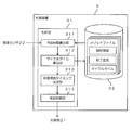
- FIG. 2 is a block diagram illustrating a configuration example of the control device 3.
- the control device 3 is constituted by a personal computer, for example, and includes a control unit 31 and a storage unit 32.
- the control unit 31 includes, for example, a CPU (Central Processing Unit). When the CPU executes a program, the cooling time calculation unit 311, the cycle time calculation unit 312, the heat insulation start timing determination unit 313, and the heat insulation control unit 314 are executed. Function as such.
- the storage unit 32 is configured by, for example, a hard disk or a RAM (Random Access Memory).
- the analysis is performed based on, for example, a method file including a plurality of types of analysis conditions.
- the method file includes the start and end temperatures of each sample during the temperature rise analysis, as well as the cycle time from the start timing of the temperature rise analysis of each sample to the start timing of the next sample temperature rise analysis.
- Various analysis conditions necessary for the analysis are included.
- the storage unit 32 functions as an analysis condition storage unit that stores the analysis conditions as described above by storing a plurality of method files.
- the cooling time calculation unit 311 performs the temperature analysis after each sample based on the room temperature detected by the room temperature sensor 22 and the start temperature and end temperature at the time of temperature increase analysis of each sample stored in the storage unit 32. Calculate the cooling time.
- the cycle time calculation unit 312 calculates the cycle time based on the cooling time after the temperature increase analysis of each sample calculated by the cooling time calculation unit 311. Specifically, the cycle time consisting of the analysis time at the time of temperature rising analysis of each sample preset in the method file, the calculated cooling time after temperature rising analysis of each sample, and a predetermined margin time, It is calculated by the cycle time calculation unit 312.
- the cycle time included in each method file stored in the storage unit 32 is changed to the cycle time calculated by the cycle time calculation unit 312. Therefore, the cycle time is not necessarily the same time during the temperature rising analysis of each sample, but is a different time depending on the room temperature.
- the margin time is set to a relatively short fixed time as a time that can prevent an error in the cooling time calculated by the cooling time calculation unit 311 from affecting the analysis of the next sample.
- the heat retention start timing determination unit 313 determines the heat retention start timing of each sample container based on the cycle time at the time of temperature increase analysis of each sample calculated by the cycle time calculation unit 312. In other words, if the cycle time for the temperature rise analysis of each sample is determined, the start timing of the temperature rise analysis for each sample is determined. Therefore, the heat retention of each sample container is started a certain time before the start timing. do it.
- the thermal insulation control unit 314 controls the thermal insulation of each sample container in the heating unit 21 of the autosampler 2.
- the heat retention control unit 314 starts the heat retention of each sample container at the heat retention start timing determined by the heat retention start timing determination unit 313, and after the sample is derived from each sample container at the start timing of the temperature rising analysis of each sample, Terminate the incubation of each sample container.
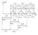
- FIG. 3 is a diagram for explaining an aspect of auto-sampling in the analyzer of FIG.
- a case will be described in which a plurality of samples A, B, C,... Are introduced into the column of the analysis unit 1 and temperature rising analysis is continuously performed on the samples A, B, C,. .
- the samples A, B, C,... Are kept warm while being overlapped, so that the processing capability can be increased.
- Sample A is introduced into the column from the start timing T11 of the temperature rising analysis, and the analysis is performed while increasing the temperature of the column until the end timing T12 of the temperature rising analysis.
- the temperature rising analysis is performed for a predetermined analysis time A11, and thereafter the column is cooled.
- the cooling time A12 of the column is a time determined in advance based on the room temperature. After a certain margin time A13 has elapsed from the cooling end timing T13, the temperature rise analysis of the next sample B is started. From the start timing T11 of the temperature rising analysis of the sample A to the start timing T21 of the next temperature rising analysis of the sample B is the cycle time A1 of the sample A.
- Sample B is introduced into the column from the start timing T21 of the temperature rising analysis, and the analysis is performed while increasing the temperature of the column until the end timing T22 of the temperature rising analysis.
- the temperature rising analysis is performed for a predetermined analysis time B11, and then the column is cooled.
- the column cooling time B12 after the temperature rising analysis of the sample B is determined in advance as a time longer than the column cooling time A12 after the temperature rising analysis of the sample A. .
- the margin time B13 is constant, and the cycle time B1 of the sample B is longer than the cycle time A1 of the sample A.
- Sample C is introduced into the column from the start timing T31 of the temperature rising analysis, and the analysis is performed while increasing the temperature of the column until the end timing T32 of the temperature rising analysis. As a result, the temperature rising analysis is performed for a predetermined analysis time C11, and thereafter the column is cooled. Although the column cooling time C12 after the temperature rising analysis of the sample C is longer than the column cooling time B12 after the temperature rising analysis of the sample B, the margin time C13 is constant. As a result, the cycle time C1 of the sample C is longer than the cycle time A1 of the sample A.
- the heat retention time A2, B2, C2,... Of each sample A, B, C As described above, the cycle times A1, B1, C1,... Of each sample A, B, C,... Differ depending on the cooling times A12, B12, C12,.
- FIG. 4 is a flowchart showing an example of processing by the control unit 31 when determining the heat retention start timing.
- a description will be given of a configuration in which the heat retention start timing of the next sample is determined at the timing when the heat retention of each sample is started.
- the present invention is not limited to such a configuration, and after starting the incubation of each sample, if the configuration is such that the incubation start timing is determined before the timing for starting the incubation of the next sample, at another timing.
- the structure which determines a heat retention start timing may be sufficient.
- step S101 when the heat retention start timing of the first sample A is reached (Yes in step S101), the end temperature at the time of temperature analysis of the sample A and the start temperature at the time of temperature analysis of the next sample B are stored in the storage unit 32. Is read out from the method file stored in (step S102). Further, the room temperature at that time is detected by the room temperature sensor 22 (step S103).
- the cooling time A12 of the sample A is calculated (step S104). Then, the cycle time A1 is calculated by adding the analysis time A11 of the temperature rising analysis of the sample A, the calculated cooling time A12 of the sample A, and the fixed margin time A13 (step S105).
- the timing before the predetermined heat retention time B2 from the start timing T21 is determined as the heat retention start timing of the sample B (step S107). Thereafter, the same processing may be repeated sequentially at the heat retention start timing of the next samples B, C,.
- the heat retention start timing of each sample container can be determined according to the room temperature detected by the room temperature sensor 22. Since the cooling rate of each sample container changes according to the room temperature, the end temperature at the time of temperature rising analysis of each sample A, B, C,... And the temperature rising analysis of the next sample B, C,. Based on the start temperature at the time and the room temperature, the cooling times A12, B12, C12,.
- the heat retention start timing is determined for each sample container, so that the margin times A13, B13, C13 after the cooling time are determined. Can be prevented from becoming unnecessarily long. Therefore, it is possible to improve the processing capacity as compared with the conventional configuration in which the heat retention start timing of each sample container is set to be shifted at a constant time interval D101, D102,... (See FIG. 5). it can.
- the end temperature at the temperature rising analysis of each sample A, B, C,... The starting temperature at the temperature rising analysis of the next sample B, C,.
- the cooling time A12, B12, C12,... Of each sample container is calculated by the cooling time calculation unit 311, and the heat retention of each sample container is started based on the cooling time A12, B12, C12,. Timing can be determined. Therefore, it is not necessary to actually measure the cooling time A112, B112, C112,... (See FIG. 5) of each sample container as in the prior art, so that the labor of the operator can be reduced.
- cycle times A1, B1, C1,... are calculated from the calculated cooling times A12, B12, C12,... Of the respective sample containers, and the cycle times A1, B1, C1,. Can be used to determine the heat retention start timing of each sample container. Therefore, it is not necessary to set constant cycle times A101, B101, C101,... (See FIG. 5) according to the sample cooling times A112, B112, C112,. Can be effectively reduced.
- the analysis device in which the analysis unit 1, the autosampler 2, and the control device 3 are integrally configured has been described.
- the present invention is not limited to this configuration.
- the auto sampler 2 to which the present invention is applied is configured individually by providing the auto sampler 2 with the functions of the control unit 31 and the storage unit 32 as shown in FIG. May be.
- each sample A, B, C,... is not limited to a configuration that is performed while overlapping. That is, the present invention can be applied to a configuration in which the heat retention of the next sample is started after the heat retention of each sample is completed.
- the present invention can be applied not only to a configuration in which a sample is introduced into the analysis unit 1 using the headspace method but also to a configuration in which the sample is introduced into the analysis unit 1 in another manner.
- the timing for starting the heat insulation of the sample tube filled with the sample may be determined using the present invention. Good.
Landscapes
- Physics & Mathematics (AREA)
- Health & Medical Sciences (AREA)
- Life Sciences & Earth Sciences (AREA)
- Chemical & Material Sciences (AREA)
- Analytical Chemistry (AREA)
- Biochemistry (AREA)
- General Health & Medical Sciences (AREA)
- General Physics & Mathematics (AREA)
- Immunology (AREA)
- Pathology (AREA)
- Sampling And Sample Adjustment (AREA)
- Investigating Or Analyzing Materials Using Thermal Means (AREA)
- Automatic Analysis And Handling Materials Therefor (AREA)
Abstract
Description
2 オートサンプラ
3 制御装置
11 カラムオーブン
12 検出器
21 加熱部
22 室温センサ
31 制御部
32 記憶部
311 冷却時間算出部
312 サイクルタイム算出部
313 保温開始タイミング決定部
314 保温制御部
A1,B1,C1 サイクルタイム
A2,B2,C2 保温時間
A11,B11,C11 分析時間
A12,B12,C12 冷却時間
A13,B13,C13 余裕時間
D1,D2 時間間隔
T11,T21,T31 昇温分析の開始タイミング
T12,T22,T32 昇温分析の終了タイミング
T13,T23,T33 冷却終了タイミング
Claims (4)
- 試料を加熱しながら昇温分析を行う分析部と、
試料が収容された複数の試料容器を順次に一定時間だけ保温して、前記一定時間が経過した試料容器から順に試料を前記分析部に導入するオートサンプラと、
各試料の昇温分析時における開始温度及び終了温度を含む分析条件を記憶する分析条件記憶部と、
室温を検知する室温センサと、
前記室温センサにより検知される室温、並びに、前記分析条件記憶部に記憶されている各試料の昇温分析時における開始温度及び終了温度に基づいて、各試料容器の保温開始タイミングを決定する保温開始タイミング決定部とを備えたことを特徴とする分析装置。 - 前記室温センサにより検知される室温、並びに、前記分析条件記憶部に記憶されている各試料の昇温分析時における開始温度及び終了温度に基づいて、各試料の昇温分析後の冷却時間を算出する冷却時間算出部をさらに備え、
前記保温開始タイミング決定部は、前記冷却時間算出部により算出された各試料の昇温分析後の冷却時間に基づいて、各試料容器の保温開始タイミングを決定することを特徴とする請求項1に記載の分析装置。 - 前記冷却時間算出部により算出された各試料の昇温分析後の冷却時間に基づいて、各試料の昇温分析の開始タイミングから次の試料の昇温分析の開始タイミングまでのサイクルタイムを算出するサイクルタイム算出部をさらに備え、
前記保温開始タイミング決定部は、前記サイクルタイム算出部により算出された各試料の昇温分析時のサイクルタイムに基づいて、各試料容器の保温開始タイミングを決定することを特徴とする請求項2に記載の分析装置。 - 試料が収容された複数の試料容器を順次に一定時間だけ保温して、前記一定時間が経過した試料容器から順に試料を分析部に導入するためのオートサンプラであって、
室温センサにより検知される室温、並びに、各試料の昇温分析時における開始温度及び終了温度に基づいて、各試料容器の保温開始タイミングを決定する保温開始タイミング決定部を備えたことを特徴とするオートサンプラ。
Priority Applications (3)
| Application Number | Priority Date | Filing Date | Title |
|---|---|---|---|
| PCT/JP2013/082368 WO2015083218A1 (ja) | 2013-12-02 | 2013-12-02 | 分析装置及びこれに用いられるオートサンプラ |
| US15/032,348 US10119926B2 (en) | 2013-12-02 | 2013-12-02 | Analytical device and autosampler used in the same |
| JP2015551281A JP6128234B2 (ja) | 2013-12-02 | 2013-12-02 | 分析装置及びこれに用いられるオートサンプラ |
Applications Claiming Priority (1)
| Application Number | Priority Date | Filing Date | Title |
|---|---|---|---|
| PCT/JP2013/082368 WO2015083218A1 (ja) | 2013-12-02 | 2013-12-02 | 分析装置及びこれに用いられるオートサンプラ |
Publications (1)
| Publication Number | Publication Date |
|---|---|
| WO2015083218A1 true WO2015083218A1 (ja) | 2015-06-11 |
Family
ID=53273016
Family Applications (1)
| Application Number | Title | Priority Date | Filing Date |
|---|---|---|---|
| PCT/JP2013/082368 Ceased WO2015083218A1 (ja) | 2013-12-02 | 2013-12-02 | 分析装置及びこれに用いられるオートサンプラ |
Country Status (3)
| Country | Link |
|---|---|
| US (1) | US10119926B2 (ja) |
| JP (1) | JP6128234B2 (ja) |
| WO (1) | WO2015083218A1 (ja) |
Families Citing this family (2)
| Publication number | Priority date | Publication date | Assignee | Title |
|---|---|---|---|---|
| US10697914B2 (en) * | 2016-09-19 | 2020-06-30 | Energy Storage & Retention Solutions Holdings, Llc | Rapid high temperature thermal analysis |
| CN110836828A (zh) * | 2019-11-22 | 2020-02-25 | 武汉大学 | 测定厚壁p91钢管正火过程心部冷却速度的方法 |
Citations (5)
| Publication number | Priority date | Publication date | Assignee | Title |
|---|---|---|---|---|
| JPH03218504A (ja) * | 1990-01-24 | 1991-09-26 | Shimadzu Corp | 温度調節装置 |
| JPH03110368U (ja) * | 1990-02-27 | 1991-11-12 | ||
| JPH11326302A (ja) * | 1998-05-13 | 1999-11-26 | Shimadzu Corp | 液体クロマトグラフ質量分析装置 |
| JP2001165920A (ja) * | 1999-12-14 | 2001-06-22 | Shimadzu Corp | サンプリング装置 |
| JP2006023280A (ja) * | 2004-06-09 | 2006-01-26 | Hitachi High-Technologies Corp | 液体クロマトグラフ |
Family Cites Families (14)
| Publication number | Priority date | Publication date | Assignee | Title |
|---|---|---|---|---|
| KR100236506B1 (ko) * | 1990-11-29 | 2000-01-15 | 퍼킨-엘머시터스인스트루먼츠 | 폴리머라제 연쇄 반응 수행 장치 |
| US5108466A (en) * | 1990-12-21 | 1992-04-28 | Hewlett-Packard Company | Apparatus and methods for controlling fluids provided to a chromatographic detector |
| US5558790A (en) * | 1994-02-15 | 1996-09-24 | Science Applications International Corporation | Method and laser system for the thermal analysis of a substance |
| US5508204A (en) * | 1995-01-12 | 1996-04-16 | Norman Clinical Laboratories, Inc. | Multiple sample sequential chemical analysis |
| ITMI981142A1 (it) * | 1998-05-22 | 1999-11-22 | Thermoquest Italia Spa | Metodo e apparecchio per l'introduzione di campioni di volume elevato in colonne capillari per gascromatografia |
| EP1703284B1 (en) * | 2003-12-25 | 2012-05-23 | ARKRAY, Inc. | Method of raising temperature of received object, and analyzing device |
| US7060946B1 (en) * | 2004-11-23 | 2006-06-13 | Shimadzu Corporation | Analytical device with temperature control system |
| US20080038163A1 (en) * | 2006-06-23 | 2008-02-14 | Applera Corporation | Systems and Methods for Cooling in Biological Analysis Instruments |
| US8075842B1 (en) * | 2008-02-27 | 2011-12-13 | EST Analytical, Inc. | Analytical chemical sampling system with sparge vessel |
| US7803635B1 (en) * | 2008-02-27 | 2010-09-28 | EST Analytical, Inc | Purge and trap concentrator with sparge vessel |
| JP5644187B2 (ja) * | 2010-05-31 | 2014-12-24 | 株式会社島津製作所 | カラムオーブン |
| US8591630B2 (en) * | 2010-10-06 | 2013-11-26 | Aviv Amirav | Fast gas chromatograph method and device for analyzing a sample |
| JP5480399B2 (ja) * | 2010-11-26 | 2014-04-23 | 株式会社日立ハイテクノロジーズ | 自動分析装置 |
| WO2013003454A2 (en) * | 2011-06-30 | 2013-01-03 | Liposcience, Inc. | Quantitative nmr clinical analyzers with automatic nmr temperature sensitivity compensation that accommodate large ambient operational temperature ranges |
-
2013
- 2013-12-02 WO PCT/JP2013/082368 patent/WO2015083218A1/ja not_active Ceased
- 2013-12-02 JP JP2015551281A patent/JP6128234B2/ja active Active
- 2013-12-02 US US15/032,348 patent/US10119926B2/en active Active
Patent Citations (5)
| Publication number | Priority date | Publication date | Assignee | Title |
|---|---|---|---|---|
| JPH03218504A (ja) * | 1990-01-24 | 1991-09-26 | Shimadzu Corp | 温度調節装置 |
| JPH03110368U (ja) * | 1990-02-27 | 1991-11-12 | ||
| JPH11326302A (ja) * | 1998-05-13 | 1999-11-26 | Shimadzu Corp | 液体クロマトグラフ質量分析装置 |
| JP2001165920A (ja) * | 1999-12-14 | 2001-06-22 | Shimadzu Corp | サンプリング装置 |
| JP2006023280A (ja) * | 2004-06-09 | 2006-01-26 | Hitachi High-Technologies Corp | 液体クロマトグラフ |
Also Published As
| Publication number | Publication date |
|---|---|
| US20160252472A1 (en) | 2016-09-01 |
| JPWO2015083218A1 (ja) | 2017-03-16 |
| JP6128234B2 (ja) | 2017-05-17 |
| US10119926B2 (en) | 2018-11-06 |
Similar Documents
| Publication | Publication Date | Title |
|---|---|---|
| CN108214087B (zh) | 机床的温度估计方法及热位移校正方法 | |
| EP3290916B1 (en) | Improved sample preparation apparatus and method for elemental analysis spectrometer | |
| JP6128234B2 (ja) | 分析装置及びこれに用いられるオートサンプラ | |
| Rink et al. | Oxygen storage in three-way-catalysts is an equilibrium controlled process: Experimental investigation of the redox thermodynamics | |
| Luis et al. | The potential of head-space gas chromatography for VLE measurements | |
| Tolley et al. | Moving thermal gradients in gas chromatography | |
| CN201548505U (zh) | 一种差热-气相色谱联用分析装置 | |
| JP2016197037A (ja) | 分取クロマトグラフ | |
| JP6119592B2 (ja) | クロマトグラム表示方法、並びに、クロマトグラム表示装置及びこれを備えたクロマトグラフ | |
| CN102445504B (zh) | 以非线性塔板理论预测多阶程序升温保留时间的方法 | |
| JP2013250061A (ja) | 元素分析装置 | |
| JP4595825B2 (ja) | 自動分析用データ処理装置 | |
| EP3299795A1 (en) | Dynamic moisture absorption-desorption property evaluation apparatus, method for evaluating dynamic moisture absorption-desorption property , and dynamic moisture absorption-desorption property evaluation program | |
| JP2014119402A (ja) | 液体クロマトグラフ間におけるシステム変換のための温度制御方法 | |
| JP2014206510A (ja) | ガスクロマトグラフ用データ処理装置、データ処理方法、及び、データ処理用プログラム | |
| JP2014157139A (ja) | 液体クロマトグラフ | |
| JP2006201064A (ja) | クロマトグラフ制御装置 | |
| JP6880354B2 (ja) | 分析測定システム | |
| CN101865868A (zh) | 差热-气相色谱联用分析装置 | |
| JP7772101B2 (ja) | ガスクロマトグラフ分析方法及びガスクロマトグラフ分析用プログラム | |
| JP7729189B2 (ja) | ガスクロマトグラフ装置 | |
| US12467912B2 (en) | Element analysis method, element analysis device, and non-transitory computer readable medium storing program for element analysis device | |
| JP2014153075A (ja) | ガス流路切替装置、ガス流路切替方法及びガス流路切替プログラム | |
| JP6204714B2 (ja) | 濃度計及び濃度測定方法 | |
| JPWO2024070027A5 (ja) |
Legal Events
| Date | Code | Title | Description |
|---|---|---|---|
| 121 | Ep: the epo has been informed by wipo that ep was designated in this application |
Ref document number: 13898804 Country of ref document: EP Kind code of ref document: A1 |
|
| ENP | Entry into the national phase |
Ref document number: 2015551281 Country of ref document: JP Kind code of ref document: A |
|
| WWE | Wipo information: entry into national phase |
Ref document number: 15032348 Country of ref document: US |
|
| NENP | Non-entry into the national phase |
Ref country code: DE |
|
| 122 | Ep: pct application non-entry in european phase |
Ref document number: 13898804 Country of ref document: EP Kind code of ref document: A1 |