WO2015080106A1 - 成分分析装置、薬効分析装置、及び分析方法 - Google Patents
成分分析装置、薬効分析装置、及び分析方法 Download PDFInfo
- Publication number
- WO2015080106A1 WO2015080106A1 PCT/JP2014/081135 JP2014081135W WO2015080106A1 WO 2015080106 A1 WO2015080106 A1 WO 2015080106A1 JP 2014081135 W JP2014081135 W JP 2014081135W WO 2015080106 A1 WO2015080106 A1 WO 2015080106A1
- Authority
- WO
- WIPO (PCT)
- Prior art keywords
- container
- amount
- buffer solution
- drug
- hepatocytes
- Prior art date
- Legal status (The legal status is an assumption and is not a legal conclusion. Google has not performed a legal analysis and makes no representation as to the accuracy of the status listed.)
- Ceased
Links
Images


Classifications
-
- B—PERFORMING OPERATIONS; TRANSPORTING
- B01—PHYSICAL OR CHEMICAL PROCESSES OR APPARATUS IN GENERAL
- B01L—CHEMICAL OR PHYSICAL LABORATORY APPARATUS FOR GENERAL USE
- B01L7/00—Heating or cooling apparatus; Heat insulating devices
-
- G—PHYSICS
- G01—MEASURING; TESTING
- G01N—INVESTIGATING OR ANALYSING MATERIALS BY DETERMINING THEIR CHEMICAL OR PHYSICAL PROPERTIES
- G01N33/00—Investigating or analysing materials by specific methods not covered by groups G01N1/00 - G01N31/00
- G01N33/48—Biological material, e.g. blood, urine; Haemocytometers
- G01N33/50—Chemical analysis of biological material, e.g. blood, urine; Testing involving biospecific ligand binding methods; Immunological testing
- G01N33/5005—Chemical analysis of biological material, e.g. blood, urine; Testing involving biospecific ligand binding methods; Immunological testing involving human or animal cells
- G01N33/5008—Chemical analysis of biological material, e.g. blood, urine; Testing involving biospecific ligand binding methods; Immunological testing involving human or animal cells for testing or evaluating the effect of chemical or biological compounds, e.g. drugs, cosmetics
- G01N33/5044—Chemical analysis of biological material, e.g. blood, urine; Testing involving biospecific ligand binding methods; Immunological testing involving human or animal cells for testing or evaluating the effect of chemical or biological compounds, e.g. drugs, cosmetics involving specific cell types
- G01N33/5067—Liver cells
-
- C—CHEMISTRY; METALLURGY
- C12—BIOCHEMISTRY; BEER; SPIRITS; WINE; VINEGAR; MICROBIOLOGY; ENZYMOLOGY; MUTATION OR GENETIC ENGINEERING
- C12M—APPARATUS FOR ENZYMOLOGY OR MICROBIOLOGY; APPARATUS FOR CULTURING MICROORGANISMS FOR PRODUCING BIOMASS, FOR GROWING CELLS OR FOR OBTAINING FERMENTATION OR METABOLIC PRODUCTS, i.e. BIOREACTORS OR FERMENTERS
- C12M25/00—Means for supporting, enclosing or fixing the microorganisms, e.g. immunocoatings
-
- C—CHEMISTRY; METALLURGY
- C12—BIOCHEMISTRY; BEER; SPIRITS; WINE; VINEGAR; MICROBIOLOGY; ENZYMOLOGY; MUTATION OR GENETIC ENGINEERING
- C12M—APPARATUS FOR ENZYMOLOGY OR MICROBIOLOGY; APPARATUS FOR CULTURING MICROORGANISMS FOR PRODUCING BIOMASS, FOR GROWING CELLS OR FOR OBTAINING FERMENTATION OR METABOLIC PRODUCTS, i.e. BIOREACTORS OR FERMENTERS
- C12M29/00—Means for introduction, extraction or recirculation of materials, e.g. pumps
-
- C—CHEMISTRY; METALLURGY
- C12—BIOCHEMISTRY; BEER; SPIRITS; WINE; VINEGAR; MICROBIOLOGY; ENZYMOLOGY; MUTATION OR GENETIC ENGINEERING
- C12M—APPARATUS FOR ENZYMOLOGY OR MICROBIOLOGY; APPARATUS FOR CULTURING MICROORGANISMS FOR PRODUCING BIOMASS, FOR GROWING CELLS OR FOR OBTAINING FERMENTATION OR METABOLIC PRODUCTS, i.e. BIOREACTORS OR FERMENTERS
- C12M41/00—Means for regulation, monitoring, measurement or control, e.g. flow regulation
- C12M41/46—Means for regulation, monitoring, measurement or control, e.g. flow regulation of cellular or enzymatic activity or functionality, e.g. cell viability
-
- C—CHEMISTRY; METALLURGY
- C12—BIOCHEMISTRY; BEER; SPIRITS; WINE; VINEGAR; MICROBIOLOGY; ENZYMOLOGY; MUTATION OR GENETIC ENGINEERING
- C12M—APPARATUS FOR ENZYMOLOGY OR MICROBIOLOGY; APPARATUS FOR CULTURING MICROORGANISMS FOR PRODUCING BIOMASS, FOR GROWING CELLS OR FOR OBTAINING FERMENTATION OR METABOLIC PRODUCTS, i.e. BIOREACTORS OR FERMENTERS
- C12M47/00—Means for after-treatment of the produced biomass or of the fermentation or metabolic products, e.g. storage of biomass
- C12M47/20—Heating or cooling
-
- G—PHYSICS
- G01—MEASURING; TESTING
- G01N—INVESTIGATING OR ANALYSING MATERIALS BY DETERMINING THEIR CHEMICAL OR PHYSICAL PROPERTIES
- G01N33/00—Investigating or analysing materials by specific methods not covered by groups G01N1/00 - G01N31/00
- G01N33/15—Medicinal preparations ; Physical properties thereof, e.g. dissolubility
-
- G—PHYSICS
- G01—MEASURING; TESTING
- G01N—INVESTIGATING OR ANALYSING MATERIALS BY DETERMINING THEIR CHEMICAL OR PHYSICAL PROPERTIES
- G01N33/00—Investigating or analysing materials by specific methods not covered by groups G01N1/00 - G01N31/00
- G01N33/48—Biological material, e.g. blood, urine; Haemocytometers
- G01N33/50—Chemical analysis of biological material, e.g. blood, urine; Testing involving biospecific ligand binding methods; Immunological testing
- G01N33/5005—Chemical analysis of biological material, e.g. blood, urine; Testing involving biospecific ligand binding methods; Immunological testing involving human or animal cells
- G01N33/5008—Chemical analysis of biological material, e.g. blood, urine; Testing involving biospecific ligand binding methods; Immunological testing involving human or animal cells for testing or evaluating the effect of chemical or biological compounds, e.g. drugs, cosmetics
- G01N33/502—Chemical analysis of biological material, e.g. blood, urine; Testing involving biospecific ligand binding methods; Immunological testing involving human or animal cells for testing or evaluating the effect of chemical or biological compounds, e.g. drugs, cosmetics for testing non-proliferative effects
-
- G—PHYSICS
- G01—MEASURING; TESTING
- G01N—INVESTIGATING OR ANALYSING MATERIALS BY DETERMINING THEIR CHEMICAL OR PHYSICAL PROPERTIES
- G01N35/00—Automatic analysis not limited to methods or materials provided for in any single one of groups G01N1/00 - G01N33/00; Handling materials therefor
- G01N35/10—Devices for transferring samples or any liquids to, in, or from, the analysis apparatus, e.g. suction devices, injection devices
- G01N35/1009—Characterised by arrangements for controlling the aspiration or dispense of liquids
-
- B—PERFORMING OPERATIONS; TRANSPORTING
- B01—PHYSICAL OR CHEMICAL PROCESSES OR APPARATUS IN GENERAL
- B01L—CHEMICAL OR PHYSICAL LABORATORY APPARATUS FOR GENERAL USE
- B01L3/00—Containers or dishes for laboratory use, e.g. laboratory glassware; Droppers
- B01L3/50—Containers for the purpose of retaining a material to be analysed, e.g. test tubes
- B01L3/508—Rigid containers without fluid transport within
- B01L3/5085—Rigid containers without fluid transport within for multiple samples, e.g. microtitration plates
-
- B—PERFORMING OPERATIONS; TRANSPORTING
- B01—PHYSICAL OR CHEMICAL PROCESSES OR APPARATUS IN GENERAL
- B01L—CHEMICAL OR PHYSICAL LABORATORY APPARATUS FOR GENERAL USE
- B01L9/00—Supporting devices; Holding devices
- B01L9/54—Supports specially adapted for pipettes and burettes
- B01L9/543—Supports specially adapted for pipettes and burettes for disposable pipette tips, e.g. racks or cassettes
-
- G—PHYSICS
- G01—MEASURING; TESTING
- G01N—INVESTIGATING OR ANALYSING MATERIALS BY DETERMINING THEIR CHEMICAL OR PHYSICAL PROPERTIES
- G01N35/00—Automatic analysis not limited to methods or materials provided for in any single one of groups G01N1/00 - G01N33/00; Handling materials therefor
- G01N2035/00346—Heating or cooling arrangements
- G01N2035/00425—Heating or cooling means associated with pipettes or the like, e.g. for supplying sample/reagent at given temperature
-
- G—PHYSICS
- G01—MEASURING; TESTING
- G01N—INVESTIGATING OR ANALYSING MATERIALS BY DETERMINING THEIR CHEMICAL OR PHYSICAL PROPERTIES
- G01N35/00—Automatic analysis not limited to methods or materials provided for in any single one of groups G01N1/00 - G01N33/00; Handling materials therefor
- G01N35/02—Automatic analysis not limited to methods or materials provided for in any single one of groups G01N1/00 - G01N33/00; Handling materials therefor using a plurality of sample containers moved by a conveyor system past one or more treatment or analysis stations
- G01N35/04—Details of the conveyor system
- G01N2035/0401—Sample carriers, cuvettes or reaction vessels
- G01N2035/0418—Plate elements with several rows of samples
Definitions
- the present invention relates to in vitro (in vitro) evaluation of pharmacokinetics such as drug uptake, metabolism, and excretion, which is useful for new drug development.
- the drug In order for the drug to exert its efficacy in the body, the drug once taken into the liver becomes a metabolite, or after being discharged to the blood vessel side without being metabolized as the original compound (parent compound) It is necessary to recirculate in the bloodstream and reach the target organ. Therefore, even in the in vitro test system, if we can measure the recirculation of drug candidate compounds excreted to the blood vessel side after administration and evaluate the efficacy, which is one of the most important indicators in new drug development, it will be a very useful drug. It can be a dynamic evaluation method.
- the entire pharmacokinetics image including the amount excreted from the cell as urine and feces after excretion of the bile duct, the amount excreted from the cell into the bile duct (disappearance), and the intracellular pool, to each fraction
- the distribution ratio can be obtained.
- Patent Document 1 and Patent Document 2 disclose a technique for evaluating a portion (disappearance) excreted from a bile duct of cells by administering a drug to cultured cells so far. This evaluation method evaluates the disappearance of the drug that is excreted into the bile duct without exhibiting toxicity or efficacy, and then excreted outside the body as urine or feces.
- the prior art is a method for evaluating the amount of gallbladder excretion, that is, the amount of a component having no medicinal effect, and a method for evaluating the disappearance from the body.
- it is desirable to directly evaluate the amount of components excreted on the blood vessel side, but in the prior art, there is no method for analyzing the amount of components excreted in blood vessels. It was not established.
- the administered drugs such as the vascular (Basal / Basolateral) drainage fraction, the luminal (Apical) drainage fraction, and the intracellular pool fraction of the administered drug
- a temperature adjustment unit that adjusts the temperature in the plurality of containers, and an analysis unit that measures a component in the plurality of containers and analyzes the measured component
- the plurality of containers include at least A first container and a second container, wherein the first container and the second container hold a first buffer solution, respectively, and the temperature adjusting unit is configured to control the temperature in the first container and the second container. Adjust so that the temperature in the container is different,
- the analysis unit includes the amount of the component discharged from the cells in the first container to the first buffer solution in the first container, and the cells in the first container from the cells in the second container.
- a component analyzer that measures the amount of the component discharged to the first buffer solution and analyzes the amount of the component discharged through the transporter of the cell.
- components such as drugs excreted on the blood vessel side of cells can be directly evaluated.
- the blood vessel (Basal / Basolateral) discharge fraction, the luminal (Apical) discharge fraction, and the intracellular residual fraction via the transporter and diffusion of drug candidate compounds (parent compound and metabolites) By quantifying and determining the total amount of drug candidate compounds administered and the distribution ratio to each fraction, it becomes possible to evaluate the dynamics of the administered drug candidate compounds. Among them, it is possible to improve in-vitro screening accuracy for drug candidates that exert their medicinal effects. As a result, drug candidate compounds can be narrowed down early, and unnecessary animal experiments and useless human clinical trials can be reduced. Contribute to reducing new drug development costs, which are a burden for pharmaceutical companies.
- Each test section has a holding area for holding cells.
- separate containers may be used for each test section, or a single container having a plurality of holding areas may be divided.
- Each test section may be set.
- Step 0 Preparation and culture of hepatocytes>
- hepatocytes are first prepared and cultured for verifying the effect of the drug. An example is shown below.
- Hepatocytes were prepared according to the in situ collagenase perfusion method. Details are as follows. Rats (5-6 weeks old) are laparotomized under pentobarbital anesthesia, a catheter is inserted into the portal vein, and preperfusion solution (Ca 2+ and Mg 2+ free, Hanks solution containing EGTA) is injected. . After confirming that blood removal from the liver is sufficient, stop perfusion. Replace the perfusate with the collagenase solution and perform perfusion. In this example, perfusion is performed using Hank's solution containing 0.05% collagenase, but this is not restrictive. After confirming that the intercellular tissue has been digested by collagenase, the perfusion is stopped.
- preperfusion solution Ca 2+ and Mg 2+ free, Hanks solution containing EGTA
- the liver is cut off, minced in cold Hanks solution, and dispersed to cells by pipetting. Use isotonic percoll solution to remove injured hepatocytes by centrifugation at 500G for 5 minutes.
- the survival rate of the obtained hepatocytes is measured by trypan blue exclusion method, and hepatocytes having a survival rate of 85% or more are used for culture.
- hepatocytes having a survival rate of 85% or more are used for the culture, but it goes without saying that the conditions are not necessarily limited thereto.
- the preparation of hepatocytes is not necessarily limited to the in situ collagenase perfusion method.
- the hepatocytes used are not limited to those derived from rats, and the strains of rats are not limited. Although hepatocytes are used in this embodiment, the present invention is not limited to this.
- hepatocytes prepared by the in situ collagenase perfusion method are suspended in a medium, and hepatocytes are suspended and seeded in a commercially available collagen-coated culture dish at a density of 5 ⁇ 10 5 cells / mL.
- the seeding density, medium, and culture plate 001 are not particularly limited.
- the culture plate is shown in FIG. Here, a 24-well culture plate including 24 culture regions (wells, 002) is shown. However, the present invention is not limited to this, and other types of containers may be used as long as they can hold predetermined cells. After sowing, culture is started under conditions of 5% CO 2 and 37 ° C. using a CO 2 incubator. After more than 18 hours, perform the first medium change.
- the medium used for culturing after 18 hours after seeding is not particularly limited.
- Matrigel was added to a medium (hereinafter referred to as medium (FCS-)) obtained by removing FCS from the medium (10% FCS +). The added medium was used. Thereafter, the medium is changed every 24 hours using the medium (FCS-).
- FCS- medium
- step 5 in order to conduct tests under three different conditions in step 5 (test sections 1, 2, and 3: detailed in step 5), three culture plates under the same conditions are prepared independently at this point. To do. In Steps 0 to 4 and Step 5, the same test operation is performed in all three types of test sections.
- Step 1 Conditioning of hepatocytes>
- the cells cultured in step 0 are prepared for conditioning suitable for drug evaluation. An example is shown below.
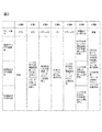
- step 2 Remove the culture supernatant of cells cultured for 4 days in step 0, add 400 L of Hanks solution as a buffer, and incubate at 37 ° C. for 10 minutes (step 1 in FIG. 2).
- the type and amount of the buffer are not particularly limited.
- step 1 it is desirable to repeat step 1 twice.
- the buffer solution for example, Hank's solution
- Step 1 it is possible to prepare a groundwork for accurate measurement and analysis in the following steps. it can.
- how many times Step 1 is repeated may be arbitrarily changed according to the type of buffer solution to be used and the type of cells.
- Step 2 Drug administration>
- a drug solution to be evaluated is administered to the cells.
- An example is shown below.
- CDF fluorescent reagent
- the type, concentration and amount of the reagent are not particularly limited. Since CDF emits fluorescence, it can be easily quantified with a plate reader as a model reagent. Moreover, although the dosage was 200 ⁇ L, this was selected as the amount by which the entire cells in the well were immersed in the reagent.
- the concentration of CDF may be any concentration conventionally used as a cell fluorescence assay. It is desirable to apply this concentration as a reagent amount for detection with a plate reader.
- the incubation time was 30 minutes, which was adopted based on the result of a preliminary study that the time required for drug uptake and excretion to be almost in equilibrium was 30 minutes.
- the plate temperature was set to 4 ° C. after 30 minutes incubation. This is because, by lowering the temperature in the container, cells cause a phenomenon of suppressing discharge of the drug to the outside.
- the temperature of the drug is set to 4 ° C., but the temperature is not limited to this as long as the administered drug can be prevented from leaking out of the cell.
- the method is not limited to a method of lowering the temperature.
- the temperature in step 2 is lower than the plate temperature set in step 1. This is because, in the conditioning in the step 1, contrary to the step 2, a temperature (for example, 37 ° C.) that activates the phenomenon in which the cell absorbs and discharges the drug is desirable.
- the timing of drug administration is not limited to this example.
- drug administration may be performed from the day before or several days before the test day.
- the drug may be administered at the stage of step 0, and steps 1 and 2 may be omitted.
- Step 3 Cell washing>
- the parts other than the drug solution contained in the cells in step 3 are washed away. An example will be described below.
- step 3 in FIG. 2 The purpose of 4 ° C. is the same as described above.
- the amount of the culture medium during the culture was 400 ⁇ L
- the amount of the washing Hanks solution was 400 ⁇ L for the purpose of removing the medium components remaining on the inner wall of the well.
- the number of washings in a general biochemical assay is usually three times, and was followed. Each condition is not limited. Thereby, it becomes possible to remove other than the chemical solution to be measured, and to further improve the accuracy of the medicinal effect evaluation in the subsequent process.
- a pretreatment buffer solution for example, Hank's solution
- Hank's solution As the buffer solution, the same type of buffer solution used in step 5 may be used, or another type of buffer solution may be used.
- the drug stored in the hepatocytes (FIG. 3, 101) up to step 3 is discharged into the Hanks solution via the first blood vessel, that is, via passive diffusion (FIG. 2, step 4, (1) ′) and trans In order to discharge through the porter (TP) (step 4 in FIG. 2, (2) ′ and 102 in the image diagram), the temperature was maintained at 37 ° C.
- the blood vessel side discharge in the step 4 is defined as the first blood vessel side discharge and the blood vessel side discharge in the step 5 is defined as the second blood vessel side discharge.
- both are steps of discharging from the cell to the blood vessel side (Basal / Basolateral) (supernatant).
- a transporter is a membrane protein responsible for transporting a substance expressed on a cell membrane. Responsible for active mass transport inside and outside the cell. Moreover, passive diffusion is the discharge
- the drug discharged into the Hanks solution in Step 4 was defined as the blood vessel side drainage fraction.
- the upper surface portion of the cell facing the Hanks solution was the Basal / Basolateral surface (FIGS. 3 and 104). This is because it is assumed in the living body that the portion faces the blood vessel.
- Step 5 to be described next is a step of collecting the drug by three different types of operations (test sections 1, 2, and 3), but before step 5, the first blood vessel as described above in step 4 is performed.
- the side discharge fraction the drug discharged into the Hanks solution
- the Hanks solution used for grasping each part of the blood vessel side discharge may be the Hanks solution of any test section.
- all of the Hanks solutions in test sections 1 to 3 described later may be evaluated, or only a part may be used.
- steps 3 and 4 are steps for performing the analysis according to the present invention in more detail and performing a highly accurate evaluation, and it is needless to say that the step 5 can be performed by skipping the present invention.
- Steps 0 to 4 are performed at least in the test sections 1 to 3, as shown in FIG.
- step 5 the test sections 1 to 3 are processed under different conditions in order to obtain a plurality of index data obtained in the present invention by analysis described later. An example is shown below.
- test section 1 collection of supernatant by 37 ° C. disintegration system>
- test group 1 as shown in test group 1 of FIG. 3, bile duct side discharge (3) and second blood vessel side discharge (that is, diffusion (1) ) And transporter (TP) (discharged from (2)).
- the Hanks (-) solution is a Hanks solution that does not contain calcium ions or magnesium ions, and is used when the intercellular adhesion intention is not strengthened as in this test section.
- a chelator such as EGTA is used as described below.
- 200 ⁇ L of Hanks ( ⁇ ) solution containing 1 mM EGTA was added.
- EGTA has a chelating action to suppress the action of Ca 2+ and Mg 2+ involved in the adhesion of intercellular adhesion molecules, and is a reagent for releasing the adhesion between cells. This disrupts the bile duct formed in the culture process. After incubation at 37 ° C. for 30 minutes, the supernatant was collected.
- the reagent is not limited to EGTA as long as it has a chelating action.
- the type, amount, and incubation temperature and time of the buffer containing EGTA are not particularly limited. In the test zone 1 of the process 5, the drug stored in the cell at the stage where the process 4 is completed (the process 5 in FIG.
- step 5 was defined as the biliary effluent fraction because the cell membrane part around the gap formed in the intercellular adhesion part corresponds to the apical surface (Fig. 3, 105) and the gap This is because it is assumed in the capillary bile duct (FIG. 3, 103).
- process 5 test group 1 the temperature is maintained at 37 ° C., so that the fraction discharged from the cell to the blood vessel side is routed via passive diffusion (step 5, (1) in FIG. 3) and via the transporter ( 3 includes step 5 and (2)).
- test section 2 collection of supernatant by 37 ° C. maintenance system>
- the test group 2 does not collapse the bile duct as in the test group 1, but discharges only the second blood vessel side discharge (diffusion (1) and transporter (2)) shown in FIG.
- test group 2 is a test group that does not contain a chelating agent such as EGTA, so that cell-cell adhesion remains maintained, and therefore capillary bile duct collapse is not induced. After incubation at 37 ° C. for 30 minutes, the supernatant was collected.
- the drug FIG. 3, step 5 and image diagrams (1) and (2) stored in the cells at the stage where step 4 is completed is discharged into the supernatant and collected.
- step 5 test section 2 the drug discharged into the supernatant is defined as the second blood vessel side discharge fraction.
- the temperature is maintained at 37 ° C., so that the fraction discharged from the cell to the blood vessel side is routed via passive diffusion (step 5, (1) in FIG. 3) and via the transporter ( 3 includes step 5 and (2)).
- the drug recovered in test zone 2 from the value obtained by quantifying the amount of drug collected in test zone 1 By subtracting the value obtained by quantifying the amount, it is possible to calculate the amount of medicine for bile duct side discharge (3) and the amount of drug for second blood vessel side discharge, respectively.
- test section 3 collection of supernatant by 4 ° C. maintenance system>
- the test group 3 suppresses the drug discharged from the transporter (1) out of the second blood vessel side discharge by setting the temperature condition to be lower than that of the test groups 1 and 2, as will be described later, and the diffusion (2) Only the discharge due to is discharged.
- test temperature is different from the process 5 test section 2 of the same maintenance system. This is to suppress blood vessel side discharge via the transporter by setting the temperature to 4 ° C.
- a low temperature 4 ° C test zone that suppresses the transporter activity in the test zone 5 of the process 5
- only the amount of discharge via passive diffusion is quantified (Fig. 3, step 5, (1)).
- Each drug has a specific transporter that moves inside and outside the cell.
- the ability to quantify the discharge amount via the transporter while eliminating the discharge amount via the passive diffusion means that the discharge amount can be quantified specifically for each drug.
- the type, amount, and incubation temperature and time of the buffer are not particularly limited.
- the fraction discharged from the transporter can be calculated from the test group 2 and the test group 3 in step 5 by quantifying the recovered drug.
- the discharge fractions are calculated using the test sections 1, 2, and 3, respectively, but the number of test sections is not necessarily three.
- Step 6 Collection of bile duct fraction and intracellular fraction>
- the operation returns to the common operation in all three test sections.
- the drug for quantifying the intracellular residual fraction is collected.
- Hank's solution containing 1% of a surfactant for example, 200 ⁇ L
- the obtained sample was transferred to a culture plate, and fluorescence measurement was performed using a plate reader. Prepare wells containing only Hanks solution for blank measurement. The fluorescence intensity is measured at an excitation wavelength of 484 nm and an absorption wavelength of 519 nm.
- LCMS mass spectrometry
- the following drug-specific scoring is possible.
- an example of the calculated CDF score is shown.
- the calculated score is not limited to these.
- the score for assessing vascular drainage via the transporter is -It is obtained by (B2-B3) / B2 as the ratio of the amount of drug discharged via the transporter to the amount of discharged drug on the second blood vessel side (Ratio of Extracellular Efflux by Diffusion, RexEMTP).
- the score for evaluating excretion into the bile duct is (B1-B2) / (C1 + C2) as a ratio of biliary excretion drug amount (Biliary Retention Drug, BiRD) to the total drug amount taken up into cells Or another way,
- the ratio of the amount of drug excreted in the bile duct to the amount of drug remaining in the cell is (C2-C1) / C2 or (B1-B2) / C1 Etc.
- the ratio of the amount of drug discharged via the transporter to the blood vessel side discharged drug amount of CDF (RexEMTP) and the ratio of the amount of bile duct excreted drug to the total amount of drug taken into cells (BiRD) are 41.08 and 18.58, while those of Rhodamine 123 are 52.52 and 4.92, indicating that CDF is more easily excreted in the bile duct than Rhodamine 123 and is less likely to be excreted on the blood vessel side.
- Example 2 describes a case where a method different from that in Example 1 is used for determination of the distribution ratio to each fraction and scoring based on the measurement result.
- the distribution ratio to each section as shown in pattern 2 in FIG. 4 is obtained from the nine types of values obtained by the fluorescence amount measurement. From these values, The first blood vessel side discharge fraction (Sup fraction) is S1 ( ⁇ S2 ⁇ S3), ⁇ Extracellular Efflux by Diffusion (ExEfx-Dif) is B3. ⁇ Extracellular Efflux by Transporter (ExEfx-TP) only via the transporter is B2-B3, ⁇ Bile duct side fraction (Bile Canaliculi Efflux, BCEfx) is B1-B2, -Intracellular residual fraction (Cell) is C1 It is corresponded to. Based on this result, a pie chart such as pattern 2 in FIG.
- Example 5 can be drawn, and the overall distribution ratio image for each fraction can be visually understood.
- Sup fraction which is an indicator of whether or not to remain in the cell, is 70.82 in CDF, and 39.29 in Rhodamine 123 (FIG. 6, pattern 2). It can be seen that CDF tends to be easily discharged to the blood vessel side. This is consistent with the intracellular residual fraction evaluation of Example 1.
- Example 3 describes an example of an apparatus that realizes automation of the series of steps described in Examples 1 and 2.
- description may be abbreviate
- a plurality of containers of the above-mentioned “well culture plate” may be set for each test section, or within one well culture plate.
- the plurality of wells may be divided, and for example, “first container”, “second container”, “third container”, or the like may be set for each divided region.
- test group 1 well and the test group 2 well perform the same temperature control, so that it is possible to evaluate more efficiently from the viewpoint of accuracy and speed by setting one well culture plate inside. Become.
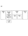
- the apparatus includes a culture unit 106, a sample preparation unit 107 (including an input unit 107A), an analysis unit 108, and a display unit 109. Further, the sample preparation unit 107 includes a temperature adjustment unit 107B that adjusts the temperature in each container (plate), which will be described later, and a liquid feeding unit 107C that can supply or recover the liquid to the container.
- the analysis unit 108 measures the amount of a component such as a drug and the amount of the component such as the drug acquired from the measurement unit, and discharges from the transporter, via the bile duct, remaining in the cell, and from other than the transporter and the bile duct There is an analysis unit 108B that analyzes each amount of the amount (diffusion).
- the above apparatus configuration is an example, and it goes without saying that, for example, only the analysis unit may be executed by another apparatus, and the information acquired from the measurement unit may be transmitted to the other apparatus.
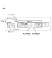
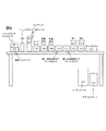
- the detailed configuration of the sample preparation unit is shown in FIGS.
- the purpose of the sample preparation unit is to automatically prepare each fraction to be analyzed as described in Example 1-2.
- Each component will be described in accordance with a flowchart described later.
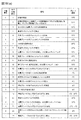
- the automatic measurement device operation flowchart is shown in FIG.
- the flowchart in FIG. 10 is merely an example, and this is not the case when the timing of drug administration is different as described in Example 1 ⁇ Step 2>.
- a container for holding cells will be described using a plate having a plurality of cell holding regions (wells) as an example.
- the container is not limited to a plate, and can hold cells. It goes without saying.
- hepatocytes are cultured in the culture unit 106 (FIGS. 7 and 10) (FIG. 10A, sub-step 1). Thereafter, the plate holding the cultured hepatocytes is transferred onto the plate holder 210 with the first temperature control function and the plate holder (211) with the second temperature control function of the sample preparation unit (FIGS. 7 and 10). (FIG. 10 (a) Sub-step 2).
- Example preparation equivalent to step 1 of Examples 1 and 2>
- a suction head 205 provided with a suction nozzle for sucking a liquid installed in the liquid feeding unit 107C moves to the well 002 of the culture plate 001 filled with the medium to be removed on the plate holder. Then, the medium is aspirated from the wells to remove the whole amount (substep 3 in FIG. 10). The removed medium is discarded and collected in the waste liquid tank 206.
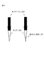
- the chip 302 holding the liquid 301 is mounted on the chip head 204 attached to the suction nozzle from the chip rack 207 in which a plurality of chips are stored.
- the chip head moves to the room temperature chemical rack 209 and sucks the buffer (substep 4 in FIG. 10).
- the chip head moves to the dust box 214, and the chip is discarded.
- a replaceable chip is used here, but this is not the case.
- the suction head moves to the well filled with the buffer and removes the buffer (FIG. 10 (a), sub-step 6).
- the removed medium is discarded and collected in the waste liquid tank 206. This process is repeated twice in total (cleaning process) (FIG. 10A, sub-process 7).
- the chip in the chip rack 207 is mounted on the chip head 204, the chip head moves to the room temperature chemical rack 209, and the buffer is sucked (substep 8 in FIG. 9). After moving to the target well and adding the buffer, the chip head moves to the dust box 214 and the chip is discarded. Wait for 10 minutes at 37 ° C. (conditioning) (FIG. 10A, sub-step 9). Thereafter, the suction head 205 moves to the well filled with the buffer, and removes the entire amount of the buffer (FIG. 9A, sub-step 10).
- Example preparation equivalent to step 2 in Examples 1 and 2>
- the chip in the chip rack 207 is mounted on the chip head 204, the chip head moves to the room temperature chemical rack 209, and sucks the chemical (substep 11 in FIG. 10 (a)).
- the chip head 204 moves to the dust box 214, and the chip is discarded. Wait for 30 minutes at 37 ° C. (FIG. 10A, sub-step 12).
- the plate holder 210 with a 1st temperature control function and the plate holder 211 with a 2nd temperature control function which are one structural example of the container holding part holding a container change from 37 degreeC to 4 degreeC (FIG.
- the suction head 205 moves to the well filled with the chemical solution, and removes the entire amount of the chemical solution (FIG. 10 (a) sub-step 14).
- the temperature adjustment unit is described as having a temperature adjustment function mounted on the plate folder, but it goes without saying that the temperature adjustment unit may exist separately from the container holding unit.
- Example preparation equivalent to step 3 in Examples 1 and 2>
- the chip in the chip rack 207 is mounted on the chip head 204, the chip head moves to the refrigerated chemical rack 208, and the buffer is sucked (substep 15 in FIG. 10 (a)).
- the refrigerated chemical solution is used to stop an active life phenomenon such as transporter activity.
- the refrigerated chemical rack 208 is used to keep chemicals, buffers and the like at a low temperature.
- the chip head 204 moves to the dust box 214, and the chip is discarded.
- the suction head moves to the well filled with the buffer, and the buffer is removed (FIG. 10A, sub-step 17).
- the removed medium is discarded in the waste liquid tank 206. This process is repeated three times in total (cleaning process) (FIG. 10 (a) sub-process 18).
- Example preparation equivalent to step 4 in Examples 1 and 2>
- the chip head 204 has the inside of the chip rack 207.
- the chip is mounted, the chip head moves to the refrigerated drug solution rack 208, and the buffer is sucked (FIG. 10A, sub-step 20).
- the chip head 204 moves to the dust box 214 and discards the chip. Wait for 30 minutes at 37 ° C. (FIG. 10A, sub-step 20).
- the chip rack 207 is mounted on the chip head 204.
- the chip inside is mounted, moved to a well filled with a buffer containing the drug, the buffer (supernatant) containing the drug is aspirated, and recovery for recovery on the first plate holder 212 and the second plate holder 213 is performed.
- Dispensing into a plate (collection) (FIG. 10 (a) sub-step 23).
- Example preparation equivalent to step 5 in Examples 1 and 2>
- the chip in the chip rack 207 is mounted on the chip head 204, and the chip head is placed in the room temperature chemical rack ( 209), the buffer containing EGTA is sucked (FIG. 10 (a) sub-step 24).
- the chip head 204 moves to the dust box 214 and discards the chip. . Wait for 30 minutes at 37 ° C. (FIG. 10B, sub-step 26).
- the chip in the chip rack 207 is mounted on the chip head 204, the chip head moves to the room temperature chemical rack 209, and the buffer is sucked (sub-step 27 in FIG. 10 (b)). After moving to the well for test section 2 on the first plate holder 212 and adding the buffer (FIG. 10B, sub-step 28), the chip head 204 moves to the dust box 214, and the chip is discarded. Wait for 30 minutes at 37 ° C. (FIG. 10B, sub-step 28).
- the chip in the chip rack 207 is mounted on the chip head 204, the chip head moves to the refrigerated chemical solution rack 209, and the buffer is sucked (substep 29 in FIG. 10 (b)).
- the chip in the chip rack 207 is mounted on the chip head 204, moved to a well filled with the EGTA buffer containing the drug, the EGTA buffer (supernatant) containing the drug is sucked, and collected on the first plate holder 212 Are dispensed (collected) onto the collecting plate (FIG. 10 (b) sub-step 31).
- the chip in the chip rack 207 is mounted on the chip head 204, moved to a well filled with a buffer containing a drug, the buffer (supernatant) containing the drug is sucked, and the recovery for recovery on the first plate holder 212 is performed. Dispensing (collecting) the plate (FIG. 10 (b), sub-step 32).
- a chip in the chip rack 207 is mounted on the chip head 204, moved to a well filled with an EGTA buffer containing a drug, a buffer (supernatant) containing the drug is sucked, and a recovery plate on the first plate holder 213 is collected. It dispenses (collects) to the collection plate (FIG. 10 (b) sub-step 33).
- the chips in the chip rack 207 are mounted on the chip head 204. Then, the chip head moves to the room temperature chemical rack 209 and sucks 1% Triton X-100 or pure water / methanol (FIG. 10 (b), sub-step 35). Move to the wells for test zones 1, 2, and 3 on the plate holder (210) with the first temperature control function and the plate holder 211 with the second temperature control function, and add 1% Triton X-100 or pure water / methanol. After the addition (FIG. 10B, sub-step 36), the chip head 204 moves to the dust box 214, and the chip is discarded.
- a chip in the chip rack 207 is mounted on the chip head 204, moved to a well filled with the reagent, and the whole cell suspension is aspirated and collected on the first plate holder 212 and the second plate holder 213. (Collecting) (collection) (FIG. 10 (b) sub-step 37).
- a holding unit that holds a plurality of containers that hold predetermined cells, a temperature adjustment unit that adjusts the temperature in the plurality of containers, and a component in the plurality of containers are measured, and the measured component is analyzed
- An analysis unit and The plurality of containers are at least a first container and a second container, wherein the first container and the second container each hold a first buffer solution, and the temperature adjusting unit is in the first container.
- the analysis unit is discharged from the cells in the first container to the first buffer solution in the first container.
- the amount of the component discharged from the cells in the second container to the first buffer solution in the second container is measured and discharged through the cell transporter.
- a component analysis apparatus that analyzes the amount of the component.
- the predetermined cell is a hepatocyte
- the plurality of containers are at least the first container, the second container, and the third container, and a predetermined substance is added to the third container.
- the second buffer solution is retained,
- the temperature adjustment unit adjusts the second temperature in the second container to be lower than the first temperature in the first container and the third container, and the analysis unit
- the amount of components discharged from the hepatocytes in one container to the first buffer solution in the first container, and from the hepatocytes in the second container to the first buffer solution in the second container The amount of the discharged component and the amount of the component discharged from the hepatocytes in the third container to the second buffer solution in the third container are measured, and the hepatocyte transporter
- the component analysis apparatus according to Configuration
- the liquid supply section further supplies or recovers the liquid in the plurality of containers, and the liquid supply section supplies the component solution containing the component to the plurality of containers, and collects the component solution.
- 3 buffer solutions are supplied into the plurality of containers, and after the third buffer solution is recovered, the first buffer solution is supplied to the first container and the second container, and the second container is supplied to the second container.
- a buffer solution is supplied, and the analysis unit measures the amount of a component discharged from the hepatocytes held in any of the plurality of culture vessels into the third buffer solution.
- the temperature adjusting unit adjusts the temperature so that the temperature in at least one of the plurality of containers when the third buffer solution is held is lower than the first temperature.
- the analysis unit includes an amount of the component remaining in the hepatocyte in the third container and a component remaining in the hepatocyte in at least one of the first container and the second container.
- a holding unit that holds a plurality of containers that hold hepatocytes that have absorbed the drug; a liquid feeding unit that supplies liquid in the plurality of containers; a temperature adjustment unit that adjusts the temperature in the plurality of containers; An analyzer that measures the amount of medicine in a plurality of containers and analyzes the measured medicine, wherein the plurality of containers are a first container, a second container, and a third container, The unit supplies a first buffer solution to the first container and the second container, and supplies a second buffer solution that promotes the discharge of the drug from the hepatocyte capillaries to the third container.
- the temperature adjustment unit adjusts the temperature so that the temperature in the second container is lower than the temperature in the first container and the third container
- the analysis unit The amount of the drug excreted from the hepatocytes in one container into the first buffer solution, and the second volume.
- a drug component analyzing apparatus characterized in that
- a holding unit that holds a plurality of containers that hold hepatocytes that have absorbed the drug; a liquid feeding unit that supplies or discharges liquid in the plurality of containers; and a temperature adjustment unit that adjusts the temperature in the plurality of containers;
- An analysis unit that measures the amount of the drug in the plurality of containers and analyzes the measured drug, and the liquid feeding unit supplies the drug to the plurality of containers, After discharging from the plurality of containers, a pretreatment buffer solution is supplied, and after the pretreatment buffer solution is recovered from the plurality of containers, the first container and the second container among the plurality of culture containers
- a first buffer solution is supplied to the third container, and a second buffer solution for urging the medicine to be discharged from the capillary bile duct of the hepatocytes is supplied to the third container, and the temperature adjusting unit is connected to the first container.
- the second container than the first temperature inside and the third container Toward the second temperature is the temperature adjusted to be lower, and
- the analysis unit is discharged from the hepatocytes in the plurality of containers into the pretreatment buffer solution, and from the hepatocytes in the first container into the first buffer solution.
- the amount of the drug, the amount of the drug discharged from the hepatocytes in the second container into the first buffer solution, and the drained from the hepatocytes in the third container into the second buffer solution The amount of the drug, the amount of the drug excreted from the hepatocytes in the pretreatment of the hepatocytes, the amount of the drug excreted from the transporter of the hepatocytes, and the capillary bile duct of the hepatocytes
- the drug component analyzer is characterized by analyzing the amount of the drug discharged from the liver and the amount of the drug discharged from other than the hepatocyte transporter and capillary bile duct.
- ⁇ Configuration 9> 9. The drug component analyzer according to Configuration 8, wherein the pretreatment buffer solution and the first buffer solution are the same type of buffer solution.
- the temperature adjusting unit adjusts the temperature so that the first temperature is higher than the temperature in at least one of the plurality of containers when the pretreatment buffer solution is held.
- the drug component analyzer according to configuration 8, wherein the drug component analyzer is adjusted.
- the analysis unit includes an amount of the component remaining in the hepatocyte in the third container and a component remaining in the hepatocyte in at least one of the first container and the second container. And measuring the amount of the remaining component other than the capillaries of the hepatocytes and analyzing the amount of the remaining component.
- the cell is a hepatocyte, and a second buffer solution to which a predetermined substance is added is held in the third container in which the hepatocyte is held.
- the first container Adjusting the second temperature in the second container to be lower than the first temperature in the inner container and the third container, and in the measurement step, the hepatocytes in the first container
- the amount of the component discharged into the first buffer solution in one container, the amount of the component discharged from the hepatocytes in the second container into the first buffer solution in the second container, and the The amount of the component discharged from the hepatocytes in the third container to the second buffer solution in the third container is measured, and in the analysis step, the amount is discharged via the hepatocyte transporter.
- the amount of the component and the hepatocyte excreted through the capillary bile duct And minute amounts a structure 12 component analysis method, wherein said the amount of the components discharged from the non-transporter and bile canaliculi of liver cells, respectively analysis.
- the liquid supply step further includes a liquid supply step of supplying or recovering liquid in a plurality of containers including at least the first container, the second container, and the third container.
- the component solution containing the component is supplied to the plurality of containers, and after the component solution is recovered, the third buffer solution is supplied into the plurality of containers and the third buffer solution is recovered, The first buffer solution is supplied to the first vessel and the second vessel, the second buffer solution is supplied to the third vessel, and held in at least one of the plurality of culture vessels in the measurement step.
- the component distribution method according to Configuration 13 wherein the amount of the component discharged from the hepatocyte into the third buffer solution is analyzed.
- ⁇ Configuration 16> Prior to the temperature adjustment step, the temperature in at least one of the plurality of containers when the third buffer solution is held is lower than the first temperature. 15.
- a liquid feeding step for supplying liquid to a plurality of containers holding hepatocytes that have absorbed the drug, a temperature adjustment step for adjusting the temperature in the plurality of containers, and the amount of the drug in the plurality of containers are measured.
- a measurement step and an analysis step for analyzing the drug measured in the measurement step wherein the plurality of containers are a first container, a second container, and a third container, and the first step in the liquid feeding step Supplying a first buffer solution to the container and the second container; supplying a second buffer solution for urging the medicine to be discharged from the capillary bile duct of the hepatocytes; And adjusting the temperature so that the temperature in the second container is lower than the temperature in the first container and the third container, and in the measuring step, the hepatocytes in the first container Amount of the drug discharged from the first buffer solution from The amount of the drug discharged from the hepatocytes in the second container into the first buffer solution, and the amount of the drug discharged from the hepatocytes in the third container into the second buffer solution; The amount of the component remaining in the hepatocytes in the third container, the amount of the component remaining in the hepatocytes in at least one of the first container and the second container, In the analysis step, the
- the drug is supplied to the plurality of containers, and the drug is discharged from the plurality of containers. Then, after supplying the pretreatment buffer solution and recovering the pretreatment buffer solution from the plurality of containers, the first buffer and the second container among the plurality of culture vessels are supplied to the first buffer.
- a second buffer solution for urging the drug to be discharged from the hepatocyte capillary bile duct is supplied to the third container.
- the first container and the third container are supplied. Than the first temperature in the container. The temperature is adjusted so that the second temperature in the two containers is lower, and in the measurement step, the amount of the drug discharged from the hepatocytes in the plurality of containers into the pretreatment buffer solution, The amount of the drug discharged from the hepatocytes in the first container into the first buffer solution, and the amount of the drug discharged from the hepatocytes in the second container into the first buffer solution; The amount of the drug discharged from the hepatocytes in the third container into the second buffer solution, the amount of the component remaining in the hepatocytes in the third container, and the first container or The amount of the component remaining in the hepatocytes in at least one of the second containers is measured, and in the analysis step, the hepatocytes are discharged from the hepatocytes in the pretreatment
- the first temperature is higher than the temperature in at least one of the plurality of containers when the pretreatment buffer solution is held.
Landscapes
- Health & Medical Sciences (AREA)
- Life Sciences & Earth Sciences (AREA)
- Engineering & Computer Science (AREA)
- Chemical & Material Sciences (AREA)
- Bioinformatics & Cheminformatics (AREA)
- Biomedical Technology (AREA)
- Immunology (AREA)
- Wood Science & Technology (AREA)
- Organic Chemistry (AREA)
- Zoology (AREA)
- General Health & Medical Sciences (AREA)
- Biochemistry (AREA)
- Biotechnology (AREA)
- Microbiology (AREA)
- Molecular Biology (AREA)
- Analytical Chemistry (AREA)
- Urology & Nephrology (AREA)
- Hematology (AREA)
- Cell Biology (AREA)
- Sustainable Development (AREA)
- Genetics & Genomics (AREA)
- General Engineering & Computer Science (AREA)
- Physics & Mathematics (AREA)
- General Physics & Mathematics (AREA)
- Pathology (AREA)
- Food Science & Technology (AREA)
- Medicinal Chemistry (AREA)
- Toxicology (AREA)
- Tropical Medicine & Parasitology (AREA)
- Clinical Laboratory Science (AREA)
- Gastroenterology & Hepatology (AREA)
- Biophysics (AREA)
- Pharmacology & Pharmacy (AREA)
- Chemical Kinetics & Catalysis (AREA)
- Measuring Or Testing Involving Enzymes Or Micro-Organisms (AREA)
- Investigating Or Analysing Biological Materials (AREA)
- Apparatus Associated With Microorganisms And Enzymes (AREA)
Abstract
本発明を適用することによって、医薬品候補化合物(親化合物および、代謝産物)のトランスポータ経由および、拡散経由での血管(Basal/Basolateral)側排出画分と管腔(Apical)側排出画分、細胞内残留画分を定量できる。これにより、投与された医薬品候補化合物の総量および、各画分への分配比率が決定できる。投与された医薬品候補化合物の動態を評価することが可能となり、膨大な数の医薬品候補化合物の中から、薬効を発揮する薬剤候補をin vitroスクリーニングすることができる。本発明は、細胞に投与した薬物の血管(Basal/Basolateral)側排出画分、管腔(Apical)側排出画分、細胞内貯留画分を定量することにより、各画分への分配比率を求め、in vitroでの薬物動態全体像を把握できる装置及び方法を提供することを目的としている。
Description
本発明は、新薬開発に有用な、薬物の取込み、代謝、排泄といった薬物動態の全体像のin vitro(生体外)での評価に関する。
新薬開発工程においては,ヒトの体内に投与し、効能を検証する臨床試験(「ヒト臨床試験」)を行うことが薬事法上必然となるが、ヒト臨床試験や動物実験試験は、莫大な開発費を要する。近年、これら開発費が最大の原因となって、新薬開発全体のコストが増大している。その原因の一つとして、開発工程前期の非臨床動物実験では薬効不良や毒性を検出できなかった薬剤候補について、開発工程後期のヒト臨床試験で初めて薬効不良や毒性が発見され、それまでの開発コストや、ヒト臨床試験にかけたコストが無駄になることに因るところが大きい。
これらの背景から、ヒト臨床試験の通過率を向上させ、新薬開発コストの削減を図るため、薬効を示し、かつ毒性を発現しない新薬候補物質を早期に絞り込むことが重要となる。そこで、多くの製薬企業から、創薬初期段階に、ヒト細胞の特性と相関の低い動物実験のみで薬剤候補を絞り込むのではなく、ヒト細胞を用いて、投与薬物のヒト体内での薬物動態を良好に予測することが可能なin vitro(生体外)評価系が望まれている。しかしながら、細胞を利用して、投与された医薬品候補化合物の取込み、代謝、胆管・血管排泄といった、薬物動態の全体像を把握、解析する手法は確立されていない。
薬剤が体内で薬効を発揮するためには、一旦肝臓に取り込まれた薬剤が、代謝産物になるか、あるいは代謝を受けずに元々の化合物(親化合物)のまま、血管側に排出された後に、再び血流に乗って再循環し、目的の臓器・器官にたどり着く必要がある。したがって、in vitro試験系においても、投与後に血管側に排出される医薬品候補化合物の再循環分を測定し、新薬開発において最も重要な指標の一つである薬効を評価できれば、非常に有用な薬物動態評価法となりえる。加えて、胆管排泄後に尿や便として体外に排泄される、細胞から胆管に排泄される分(消失分)、細胞内貯留分を含んだ薬物動態全体像を把握することにより、各画分への分配比率が求めることができるようになる。
特許文献1及び特許文献2には、これまでに培養細胞に薬剤を投与し、細胞の胆管から排泄される分(消失分)を評価する手法が開示されている。この評価方法は、投与薬剤が毒性や薬効を発揮せずに胆管に排泄され、その後、尿や便として体外に排泄される薬剤消失分の評価を行うものである。
従来技術はあくまでも胆菅排泄量、つまりは薬効のなかった成分の量を評価する方法であり、体外消失分を評価する方法であった。しかし,薬効のある成分の情報を得るためには,血管側に排泄される成分の量を直接的に評価することが望ましいが、従来技術では血管に排泄される成分の量を解析する方法は確立されていなかった。さらには、薬物動態の一部を評価できるのではなく、投与薬剤の血管(Basal/Basolateral)側排出画分、管腔(Apical)側排出画分、細胞内貯留画分をといった、投与薬剤が細胞のどこから排泄され、どこに貯留しているのか、細分化して定量することにより、in vitroでの薬物動態全体像を提供し、より精度の高い薬効評価を行うことができるが、このような評価方法についても確立されていなかった。
例えば、前記複数の容器内の温度を調整する温度調整部と、前記複数の容器内の成分を測定し、当該測定した前記成分を解析する分析部と、を備え、前記複数の容器は、少なくとも第1容器、第2容器であって、前記第1容器内及び前記第2容器は、夫々第1バッファ液を保持し、前記温度調整部は、前記第1容器内の温度と、前記第2容器内の温度とが異なる温度となるように調整し、
前記分析部は、前記第1容器内の細胞から、前記第1容器内の前記第1バッファ液へ排出された成分の量と、前記第2容器内の細胞から、前記第1容器内の前記第1バッファ液へ排出された成分の量と、を測定し、前記細胞のトランスポータを介して排出される前記成分の量を解析することを特徴とする成分分析装置である。
前記分析部は、前記第1容器内の細胞から、前記第1容器内の前記第1バッファ液へ排出された成分の量と、前記第2容器内の細胞から、前記第1容器内の前記第1バッファ液へ排出された成分の量と、を測定し、前記細胞のトランスポータを介して排出される前記成分の量を解析することを特徴とする成分分析装置である。
本発明を適用することによって、細胞の血管側に排泄された薬剤等の成分を直接的に評価することができる。さらに、医薬品候補化合物(親化合物および、代謝産物)のトランスポータ経由および、拡散経由での血管(Basal/Basolateral)側排出画分と管腔(Apical)側排出画分、細胞内残留画分を定量し、投与された医薬品候補化合物の総量および、各画分への分配比率を判定することによって、投与された医薬品候補化合物の動態を評価することが可能となり、膨大な数の医薬品候補化合物の中から、薬効を発揮する薬剤候補をin vitroでのスクリーニング精度を向上させることができる。結果として、医薬品候補化合物の早期の絞り込みを可能とし、無駄な動物実験や、無用なヒト臨床試験を減少させることができる。製薬企業にとって重荷となっている新薬開発コスト低減に貢献する。
本実施例では、上述の薬効評価のための成分分析方法について図2の工程0~6に則して説明する。また、工程4~6については、図3を用いて詳述する。
尚、以下の複数の実施例においては、薬効成分の評価方法に基づいて説明するが、あくまでも本願発明を説明するための一例であって、薬剤以外の化学物質、さらには薬物代謝物の評価にも本願発明の成分分析方法を適用できることは言うまでもない。また、本実施例にて示す、バッファ液や温度、時間等の具体的な条件は、あくまでも一例であって、技術思想として同様の効果を有するのであれば別の条件を適用してもよいことは言うまでもない。
本実施例においては、試験区1~3の、少なくとも3つの試験区を用いた場合について説明する。各試験区には、細胞を保持する保持領域が存在するが、これら保持領域は、各試験区ごとに別々の容器を用いてもよいし、複数の保持領域を有する一つの容器内を区切って、各試験区を設定してもよい。
<工程0:肝細胞の調製と培養>
本工程では、まず薬剤の効果を検証するための肝細胞の調製・培養を行う。以下一例を示す。
本工程では、まず薬剤の効果を検証するための肝細胞の調製・培養を行う。以下一例を示す。
肝細胞の調製は、in situコラゲナーゼかん流法にしたがった。詳しくは以下の通りである。ラット(5~6週齢)を、ペントバルビタール麻酔下で開腹し、門脈にカテーテルを挿入して前かん流液(Ca2+とMg2+不含、EGTAを含むハンクス液)を注入する。肝臓からの脱血が十分になされたことを確認した後にかん流を止める。かん流液をコラゲナーゼ溶液に換えて、かん流を行う。本実施例では0.05%コラゲナーゼ含むハンクス液を用いてかん流を行うが、この限りではない。細胞間組織がコラゲナーゼにより消化されたことを確認した後、かん流を止める。肝臓を切り離し、冷したハンクス液中で細切りし、ピペッティングにより細胞まで分散する。等張パーコール液を使用して500G、5分の遠心分離で傷害のある肝細胞を除去する。得られた肝細胞の生存率はトリパンブルー排除法で計測し、生存率85%以上の肝細胞を培養に使用する。ここでは、生存率85%以上の肝細胞を培養に使用するが、必ずしも当該条件に限られるものではないことは言うまでもない。また、肝細胞の調製は必ずしもin situコラゲナーゼかん流法に限られるものではない。用いる肝細胞もラット由来のものに限らないし,ラットの系統も限定されない。本実施例では肝細胞を利用したが、これに限らない。
前述の通りin situコラゲナーゼかん流法により調製した肝細胞を培地に懸濁し、市販のコラーゲンコート培養ディッシュに肝細胞を5X10⁵ cells/mLの密度で培地に懸濁し播種する。播種密度、培地、培養プレート001は特に限定されない。培養プレートを図1に示す。ここでは24個の培養領域(ウェル、002)を含む24ウェル培養プレートを示したが、これに限らず所定の細胞を保持できる容器であれば他の形状の容器を用いても良い。播種後、CO2インキュベータを用いて5%CO2、37℃の条件下で培養を開始する。18時間以上経過した後に、最初の培地交換を行う。播種後18時間目以降の培養に用いる培地は特に限定されるものではないが、本実施例では、培地(10%FCS+)からFCSを除いた培地(以下、培地(FCS-))にマトリゲルを添加した培地を用いた。以降24時間毎に培地(FCS-)を用いて培地交換を行う。後述するように、工程5で3種類の異なる条件下での試験(試験区1、2、3:工程5で詳述)を行うため、この時点で同条件の培養プレートを独立に3プレート用意する。工程0から4、および工程5においては、3種類の試験区とも同一の試験操作を行う。
<工程1:肝細胞のコンディショニング>
本工程では、工程0にて培養した細胞を、薬剤評価に適したコンディショニングに整える。以下一例を示す。
本工程では、工程0にて培養した細胞を、薬剤評価に適したコンディショニングに整える。以下一例を示す。
工程0によって4日間培養した細胞の培養上清を除去し、バッファとしてハンクス液を400・L添加し、37℃で10分インキュベーションする(図2工程1)。バッファの種類と量は特に限定されるものではない。
工程1の操作は2回繰り返すのが望ましい。このように工程0の培養にて使用した培地から、バッファ液(例えばハンクス液)へ細胞が馴染む成分を置換させることにより、以下の工程で正確な測定・解析を行うための下地を整えることができる。ただし、工程1を何度繰り返すかは、使用するバッファ液の種類や細胞の種類によって、任意に変更してもよいことは言うまでもない。
<工程2:薬液投与>
本工程では、評価を行う薬液を細胞に投与する。以下一例を示す。
本工程では、評価を行う薬液を細胞に投与する。以下一例を示す。
バッファを除去後、10・MのCDF(蛍光試薬)200・Lをウェルに添加し、37℃で30分間インキュベーションし、その後に4℃で5分間保持した(図2工程2)。試薬の種類、濃度、量は特に限定されるものではない。CDFは蛍光を発するため、モデル試薬としてプレートリーダで簡便に定量できる。また、投与量を200μLとしたが、これはウェル内の細胞全体が試薬に浸る量として選択した。CDFの濃度は細胞の蛍光アッセイとして従来用いられている濃度であれば良い。プレートリーダで検出するための試薬量としても本濃度を適用することが望ましい。インキュベーションの時間は30分としたが、これは薬剤の取り込みと排出がほぼ平衡状態になるまでの時間が30分であるという予備検討の結果をもとに採用した。投与された薬剤の細胞外への漏出を防ぐ目的で、30分インキュベーション後にプレート温度を4℃にした。容器内の温度を低くすることにより、細胞は薬剤を外部へ排出すること抑制する現象を生じさせるからである。
このように薬剤の温度を所定の温度以下にすることにより、薬剤は細胞内へ留まり、細胞外へ漏出する現象を抑制することができる。本実施例では4℃としたが、投与された薬剤が細胞外へ漏出することを抑制できる温度であればこれに限られるものではない。また、投与された薬剤が細胞外へ漏出することを抑制できる、例えばインヒビターを投与するような方法があれば、温度を下げる方法に限らない。いずれにせよ、工程1で設定したプレート温度よりも、工程2における温度の方が低い温度となる。工程1でのコンディショニングでは工程2とは逆に、細胞内が薬剤を吸収・排出する現象が活性化する温度(例えば37℃)の方が望ましいからである。
薬剤投与のタイミングは、本実施例に限定されるものではない。例えば、薬剤投与を試験日の前日もしくは数日前から行う場合もある。この場合は、工程0の段階で薬剤を投与し、工程1、2は省略してもよい。
<工程3:細胞洗浄>
本工程では、工程3によって細胞内に含まれた薬液以外を洗い流す。以下一例を説明する。
本工程では、工程3によって細胞内に含まれた薬液以外を洗い流す。以下一例を説明する。
次に、プレートを4℃に保持したまま、氷冷したハンクス液400μLを用いて3回洗浄した(図2工程3)。4℃の目的は上記と同様である。培養時の培地の量が400μLであり、ウェル内壁に残留している培地成分を除去する目的で、洗浄ハンクス液の量を400μLとした。一般的な生化学アッセイでの洗浄回数は3回が通例となっており、踏襲した。各条件は限定されない。これにより、測定対象となる薬液以外を除去し、後の工程における薬効評価の精度をより向上させることが可能となる。
<工程4:血管側排出画分回収>
薬効を評価する一つの指標として、投与した薬剤が、細胞内に長時間留まりやすいものであるか、または短期間しか留まりにくいものであるかを分析することが有効である。そこで本工程では、上記指標のためのデータを取得するべく、後述の工程5にて各試験区内の細胞を評価する前に、薬剤が細胞内から所定時間以内に漏出させる。以下一例を示す。
薬効を評価する一つの指標として、投与した薬剤が、細胞内に長時間留まりやすいものであるか、または短期間しか留まりにくいものであるかを分析することが有効である。そこで本工程では、上記指標のためのデータを取得するべく、後述の工程5にて各試験区内の細胞を評価する前に、薬剤が細胞内から所定時間以内に漏出させる。以下一例を示す。
まず、前処理用のバッファ液(例えばハンクス液)を投与し、37℃で30分間インキュベーションし、薬剤を含むハンクス液(上清)を回収した(図2工程4)。バッファ液は、工程5にて使用するバッファ液と同一種のものを使用してもよいし、別の種類のものを使用してもよい。工程3までにより肝細胞(図3、101)内に貯留させた薬剤を、ハンクス液中に、第一血管側排出、つまりは受動拡散経由(図2工程4、(1)’)および、トランスポータ(TP)経由(図2工程4、(2)’およびイメージ図中102)で排出させるため、37℃に維持した。後述の通り、工程5においても血管側排出が行われるため、区別するため、工程4おける血管側排出を第一血管側排出、工程5における血管側排出を第二血管側排出と定義した。本質的には、ともに細胞内から血管側(Basal/Basolateral)(上清)に排出される工程である。トランスポータは細胞膜上に発現している物質輸送を担う膜タンパク質である。細胞内外での能動的な物質輸送を担う。また、受動拡散は、トランスポータ経由以外による細胞外への排出であり、細胞膜からの漏出等を含む。工程4でハンクス液に排出された薬剤を血管側排出画分と定義したのは、ハンクス液に面している細胞上面部分は、ベーサル(Basal)/バソラテラル(Basolateral)面(図3、104)に相当し、生体内では血管に面している部分と想定されるためである。
次に説明する工程5では、異なる3種類の操作で薬剤の回収を行う工程(試験区1、2、3)となるが、工程5の前に、工程4にて上述のように第一血管側排出画分(ハンクス液に排出された薬剤)を取得しておくことにより、薬剤が細胞に留まりやすいものかどうかを検証する指標を取得することができる。
尚、血管側排出各分を把握するのに用いるハンクス液は、どの試験区のハンクス液を用いてもよい。例えば、後述の試験区1~3すべてのハンクス液について評価してもよいし、一部のみ用いても良い。
また、工程3や4は本発明による分析をより詳細に実施し高精度の評価を行うための工程であって、本発明をスキップして工程5の作業を行うことも可能であることは言うまでもない。上記工程0~4は、図2に示すように、少なくとも試験区1~3において行われるものである。工程5では、本発明で求める複数の指標データを後述の解析によって取得するべく、試験区1~3夫々について、別条件で処理を行う。以下一例を示す。
<工程5、試験区1:37℃崩壊系による上清の回収>
試験区1では、図3の試験区1にて示すように、細胞からバッファ液(例えばハンクス(-)液)に、胆管側排出(3)と、第二血管側排出(つまりは拡散(1)とトランスポータ(TP)(2)とからの排出)との合算分を排出させる。ハンクス(-)液は、カルシウムイオンやマグネシウムイオンを含まないハンクス液のことであり、本試験区のような細胞間接着あえてを強化しない場合等に用いる。細胞間接着を積極的に解除する目的としては、以下述べるようにEGTAのようなキレーターを用いる。次に、1mMのEGTAを含むハンクス(-)液を200μL添加した。EGTAは細胞間接着分子の接着に関与しているCa2+、Mg2+の作用を抑えるキレート作用を持ち、細胞間接着を解除するための試薬である。これにより培養過程において形成された胆管を崩壊させる。37℃で30分間インキュベーションした後に、上清を回収した。キレート作用を持つ試薬であればEGTAに限定されない。EGTAを含むバッファの種類、量、およびインキュベーション温度と時間は特に限定されない。工程5の試験区1では、工程4が終了した段階で細胞内に貯留している薬剤(図3工程5、およびイメージ図(1)、(2))、および胆管に排出されている薬剤(図3工程5およびイメージ図(3))がすべて上清中に排出され、回収される(図3工程5、試験区1)。工程5で(3)を胆管側排出画分と定義したのは、細胞間接着部分に形成される間隙周囲の細胞膜部分は、アピカル(Apical)面(図3、105)に相当し、かつ間隙は毛細胆管(図3、103)に想定されるためである。工程5試験区1では、温度は37℃に維持されているため、細胞内から血管側に排出される画分には受動拡散経由(図3工程5、(1))、およびトランスポータ経由(図3工程5、(2))が含まれる。
試験区1では、図3の試験区1にて示すように、細胞からバッファ液(例えばハンクス(-)液)に、胆管側排出(3)と、第二血管側排出(つまりは拡散(1)とトランスポータ(TP)(2)とからの排出)との合算分を排出させる。ハンクス(-)液は、カルシウムイオンやマグネシウムイオンを含まないハンクス液のことであり、本試験区のような細胞間接着あえてを強化しない場合等に用いる。細胞間接着を積極的に解除する目的としては、以下述べるようにEGTAのようなキレーターを用いる。次に、1mMのEGTAを含むハンクス(-)液を200μL添加した。EGTAは細胞間接着分子の接着に関与しているCa2+、Mg2+の作用を抑えるキレート作用を持ち、細胞間接着を解除するための試薬である。これにより培養過程において形成された胆管を崩壊させる。37℃で30分間インキュベーションした後に、上清を回収した。キレート作用を持つ試薬であればEGTAに限定されない。EGTAを含むバッファの種類、量、およびインキュベーション温度と時間は特に限定されない。工程5の試験区1では、工程4が終了した段階で細胞内に貯留している薬剤(図3工程5、およびイメージ図(1)、(2))、および胆管に排出されている薬剤(図3工程5およびイメージ図(3))がすべて上清中に排出され、回収される(図3工程5、試験区1)。工程5で(3)を胆管側排出画分と定義したのは、細胞間接着部分に形成される間隙周囲の細胞膜部分は、アピカル(Apical)面(図3、105)に相当し、かつ間隙は毛細胆管(図3、103)に想定されるためである。工程5試験区1では、温度は37℃に維持されているため、細胞内から血管側に排出される画分には受動拡散経由(図3工程5、(1))、およびトランスポータ経由(図3工程5、(2))が含まれる。
<工程5、試験区2:37℃維持系による上清の回収>
試験区2は、試験区1のように胆管を崩壊させず、図3に言う第二血管側排出(拡散(1)とトランスポータ(2))のみを排出させる。
試験区2は、試験区1のように胆管を崩壊させず、図3に言う第二血管側排出(拡散(1)とトランスポータ(2))のみを排出させる。
ハンクス液は200μL添加した。試験区2は、試験区1とは異なり、EGTA等のキレート剤を含まないため、細胞間接着は維持されたままであり、したがって、毛細胆管の崩壊も誘起されない試験区である。37℃で30分間インキュベーションした後に、上清を回収した。工程5の試験区2では、工程4が終了した段階で細胞内に貯留している薬剤(図3工程5、およびイメージ図(1)、(2))が上清中に排出され、回収される(図3工程5、試験区2)。これまでの説明にしたがい、上清中に排出される薬剤は、第二血管側排出画分と定義される。工程5試験区2では、温度は37℃に維持されているため、細胞内から血管側に排出される画分には受動拡散経由(図3工程5、(1))、およびトランスポータ経由(図3工程5、(2))が含まれる。
工程5の試験区1と試験区2から、回収した薬剤の量を定量的に解析することにより、例えば、試験区1で回収した薬剤量を定量化した値から、試験区2で回収した薬剤量を定量化した値を減算することにより、胆管側排出(3)の薬剤量と、第二血管側排出の薬剤量を夫々算出することができる。
<工程5、試験区3:4℃維持系による上清の回収>
試験区3は、後述のように試験区1,2よりも低い温度条件とすることで、第二血管側排出のうち、トランスポータ(1)から排出される薬剤を抑制し、拡散(2)による排出分のみを排出させる。
試験区3は、後述のように試験区1,2よりも低い温度条件とすることで、第二血管側排出のうち、トランスポータ(1)から排出される薬剤を抑制し、拡散(2)による排出分のみを排出させる。
ハンクス液を200μL添加し、4℃で30分間インキュベーションした後に、上清を回収した。同じ維持系の工程5試験区2とは試験温度が異なる。これは、4℃にすることにより、トランスポータ経由の血管側排出を抑制させるためである。工程5試験区3において、トランスポータ活性を抑制させる低温4℃の試験区を採用することにより、受動拡散経由の排出量のみを定量し(図3工程5、(1))、工程5試験区2との比較においてトランスポータ経由による血管側薬剤排出量を算出(定量)することが可能となる。各薬剤には細胞内外を移動するための特異的なトランスポータが存在する。したがって、受動拡散経由の排出量を排除し、トランスポータ経由での排出量を定量できることは、各薬剤に特異的は排出量を定量できることを意味する。バッファの種類、量、およびインキュベーション温度と時間は特に限定されない。上述同様に、工程5の試験区2と試験区3から、回収薬剤を定量することにより、トランスポータ経由の排出画分を算出することができる。尚、本実施例では試験区1,2,3を用いて排出画分を夫々算出する例について示したが、試験区の数は必ず3つである必要はない。例えば、胆管側排出(3)と、第二血管側排出((1)+(2))のみを分離したいのであれば、試験区1および2のみを実施すればよいし、第二血管側排出において、拡散(1)とトランスポータ(2)を単に分離したいのであれば、試験区2,3のみを実施すればよい。また、必要に応じて、別途4℃の崩壊系を設けることにより、毛細胆管側への排出のうち、トランスポータ経由の排出を抑制し、拡散による排出分のみを測定することができる。これにより、例えば、この4℃崩壊系と試験区3との比較から、拡散による毛細胆管側への排出とトランスポータ経由による毛細胆管側への排出分を切り分けて評価することが可能となる。
上述した試験区1~3夫々における工程は、どの順番で行ってもよいし、各工程を並行して実施してもよい。
<工程6:胆管画分、細胞内画分の回収>
再び工程6では3試験区とも共通の操作に戻る。工程6では、細胞内残留画分の定量を行うための薬剤の回収を行う。蛍光薬剤等をプレートリーダ等を用いて定量を行う場合には、1%の界面活性剤を含むハンクス液を例えば200μL添加し、懸濁し、全量を回収することが望ましい(図2工程6)。これにより、細胞膜を破砕し、細胞内に残留する薬剤を排出させることが可能となる。得られたサンプルを培養プレートに移し、プレートリーダを用いて蛍光計測を行った。ブランク測定用にハンクス液のみを添加したウェルを準備する。励起波長484nm、吸収波長519nmで蛍光強度を測定する。
再び工程6では3試験区とも共通の操作に戻る。工程6では、細胞内残留画分の定量を行うための薬剤の回収を行う。蛍光薬剤等をプレートリーダ等を用いて定量を行う場合には、1%の界面活性剤を含むハンクス液を例えば200μL添加し、懸濁し、全量を回収することが望ましい(図2工程6)。これにより、細胞膜を破砕し、細胞内に残留する薬剤を排出させることが可能となる。得られたサンプルを培養プレートに移し、プレートリーダを用いて蛍光計測を行った。ブランク測定用にハンクス液のみを添加したウェルを準備する。励起波長484nm、吸収波長519nmで蛍光強度を測定する。
また、薬剤を質量分析(LCMS)装置等を用いて定量する場合には、水添加による低張化、有機溶剤処理等により、細胞内残留分抽出後にメタノール等の有機溶剤を用いて懸濁し、全量を回収する(図2工程6)。その後、LCMS装置を用い、後述のように薬剤の定量を行う。
<測定結果をもとにした各画分への分配比率の決定、およびスコア付け>
上記工程により得られた薬剤量を反映した蛍光強度をもとに、各画分への分配比率を計算する。ここでは、工程5、6の総和(図3、B#+C#=(1)+(2)+(3)+(4))を薬剤量100%とする。この場合を「パターン1」とする。
上記工程により得られた薬剤量を反映した蛍光強度をもとに、各画分への分配比率を計算する。ここでは、工程5、6の総和(図3、B#+C#=(1)+(2)+(3)+(4))を薬剤量100%とする。この場合を「パターン1」とする。
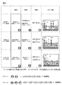
蛍光量測定により求めた6種類の値(B1、B2、B3、C1、C2、C3)から、図4のパターン1に示すような各区分への分配比率が求められる。これらの値から、
・拡散のみによる第二血管側排出画分(Extracellular Efflux by Diffusion、ExEfx-Dif)はB3、
・トランスポータ経由のみによる第二血管側排出画分(Extracellular Efflux by Transporter、ExEfx-TP)はB2-B3、
・胆管側排出画分(Bile Canaliculi Efflux、BCEfx)はB1-B2、
・細胞内残留画分(Cell)はC1
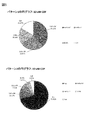
に対応づけられる。この結果をもとに、図5のパターン1のような円グラフが描画でき、各画分への分配比率の全体像を視覚的に理解することが可能となる。
・拡散のみによる第二血管側排出画分(Extracellular Efflux by Diffusion、ExEfx-Dif)はB3、
・トランスポータ経由のみによる第二血管側排出画分(Extracellular Efflux by Transporter、ExEfx-TP)はB2-B3、
・胆管側排出画分(Bile Canaliculi Efflux、BCEfx)はB1-B2、
・細胞内残留画分(Cell)はC1
に対応づけられる。この結果をもとに、図5のパターン1のような円グラフが描画でき、各画分への分配比率の全体像を視覚的に理解することが可能となる。
さらに、定量結果をもとに、以下のような薬剤固有のスコア付けが可能になる。本実施例では、算出したCDFのスコアの一例を示す。算出されるスコアはこれらに限らない。
トランスポータ経由での血管側排出を評価するスコアは、
・第二血管側排出薬剤量に対するトランスポータ経由で排出された薬剤量の割合(Ratio of Extracellular Efflux by Diffusion、RexEMTP)として(B2-B3)/B2によって求められる。
・第二血管側排出薬剤量に対するトランスポータ経由で排出された薬剤量の割合(Ratio of Extracellular Efflux by Diffusion、RexEMTP)として(B2-B3)/B2によって求められる。
胆管への排泄を評価するスコアは、
・細胞内に取り込まれた全薬剤量に対する胆管排泄薬剤量の割合(Biliary Retention Drug、BiRD)として(B1-B2)/(C1+C2)、
または、別法の、
・細胞内に残留している薬剤量に対する胆管排泄薬剤量の割合として(C2-C1)/C2、あるいは(B1-B2)/C1
等によって求められる。
・細胞内に取り込まれた全薬剤量に対する胆管排泄薬剤量の割合(Biliary Retention Drug、BiRD)として(B1-B2)/(C1+C2)、
または、別法の、
・細胞内に残留している薬剤量に対する胆管排泄薬剤量の割合として(C2-C1)/C2、あるいは(B1-B2)/C1
等によって求められる。
<異なる薬剤間の分配比率およびスコアの比較>
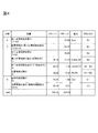
CDFをRhodamine123に変えて上記と同様の操作により、図6に示す結果(パターン1)を得ることができる。CDFの結果を示す図5(パターン1)とは明らかに異なる分配比率を検出できることが分かる。
CDFをRhodamine123に変えて上記と同様の操作により、図6に示す結果(パターン1)を得ることができる。CDFの結果を示す図5(パターン1)とは明らかに異なる分配比率を検出できることが分かる。
また、例えば、CDFの血管側排出薬剤量に対するトランスポータ経由で排出された薬剤量の割合(RexEMTP)と、細胞内に取り込まれた全薬剤量に対する胆管排泄薬剤量の割合(BiRD)は、それぞれ、41.08、18.58であるのに対し、Rhodamine123のそれらは、52.52、4.92となり、CDFはRhodamine123に比べて胆管に排泄されやすく、血管側には排出されにくい性質を保持した薬剤であることがわかる。以上のように、本発明により、それぞれの化合物がどのような薬物動態を示すかを評価することが可能になる。
実施例2では、測定結果をもとにした各画分への分配比率の決定、およびスコア付けについて、実施例1とは異なる方法を用いた場合について説明する。
本実施例では、図3に記載のS#(工程4に相当)の定量値を利用することにより、実施例1のパターン1で示した各画分への分配比率に加えて、投与薬物が細胞内に留まりやすいのか、留まりにくいのかの情報も与えることができ、より精密な評価をすることが可能となる。すなわち、工程4、5、6の総和(図3、S#+B#+C#=(1)’+(2)’+(1)+(2)+(3)+(4))を100%の投与薬物量とする。この場合を「パターン2」とする。したがって、工程4、5、6の各試験区により求められる9種類(S1、S2、S3、B1、B2、B3、C1、C2、C3)を評価指標として用いることができる。
蛍光量測定により求めた9種類の値から、図4のパターン2に示すような各区分への分配比率が求められる。これらの値から、
・第一血管側排出画分(Sup画分)はS1(≒S2≒S3)、
・拡散のみによる第二血管側排出画分(Extracellular Efflux by Diffusion、ExEfx-Dif)はB3、
・トランスポータ経由のみによる第二血管側排出画分(Extracellular Efflux by Transporter、ExEfx-TP)はB2-B3、
・胆管側排出画分(Bile Canaliculi Efflux、BCEfx)はB1-B2、
・細胞内残留画分(Cell)はC1
に対応づけられる。この結果をもとに、図5のパターン2のような円グラフが描画でき、各画分への分配比率全体像を視覚的に理解することが可能となる。実施例2で示した方法を用いることにより、細胞内に留まりやすいか留まりにくいかの指標となるSup画分が、CDFでは70.82であるのに対し、Rhodamine123では39.29(図6、パターン2)となり、CDFが血管側に排出されやすい傾向にあることがわかる。このことは、実施例1の細胞内残留画分評価に一致する。
さらに、定量結果をもとに、薬剤固有のスコア付けが可能になるが、これは実施例1に記載の通りである。
実施例3では、実施例1および2で述べてきた一連の工程を自動化を実現する装置の一例について述べる。尚、後述する装置の動作の目的、各構成の役割等について、上記実施例1,2と重複する場合は、記載を省略する場合がある。
実施例1~2で示した試験区1~3の夫々に設定される細胞を保持する領域について、後述する装置構成においては、「試験区1用ウェル」「試験区2用ウェル」「試験区3用ウェル」等の表現を用いて説明するが、これらは、例えば上述の「ウェル培養プレート」の複数の容器を夫々の試験区ごとに設定してもよいし、一つのウェル培養プレートの中の複数のウェルを区切って、区切った領域ごとに、例えば「第1容器」「第2容器」「第3容器」等として設定してもよい。
特に試験区1用ウェルと試験区2用ウェルは、ほぼ同じ温度調整を行うため、ひとつのウェル培養プレート内を区切って設定した方が精度や速度の観点から効率的に評価することが可能となる。
尚、後述の装置動作について各試験区用ウェル(容器)の交換作業については、自動で交換しても手作業で交換してもよい。当該容器の交換や設置作業については、以下省略して説明することとする。
本装置は、図7に示すように、培養部106、サンプル調製部107(含む入力部107A)、分析部108、および表示部109により構成される。さらにサンプル調製部107は、後述する各容器(プレート)内の温度を調整する温度調整部107Bと、液体を容器に供給または回収可能な送液部107C等を有している。分析部108は、薬剤等の成分の量を測定する測定部108Aと、測定部から取得した薬剤等の成分の量から、トランスポータ経由、胆管経由、細胞内残存、トランスポータと胆管以外から排出される分(拡散)の夫々の量を解析する解析部108Bを有する。上記装置構成は一例であり、例えば解析部のみ別の装置に実行させ、当該別の装置に測定部から取得した情報を送信する等の構成としてもよいことは言うまでもない。
また、サンプル調製部の詳細構成を図8、および9に示す。サンプル調製部では、これまで実施例1-2で述べてきたように、分析対象となる各画分を自動調製することが目的となる。各構成要素の説明は、後述のフローチャートにしたがって述べる。
自動計測装置動作フローチャートは図10に示す。図10のフローチャートは一例にすぎず、実施例1<工程2>に記載の通り、薬剤投与のタイミングが異なる場合は、この限りではない。本実施例においては、細胞を保持する容器について、複数の細胞保持領域(ウェル)を有するプレートを一例として用いて説明するが、容器はプレートに限られるものでなく、細胞を保持できるものであれば良いことは言うまでもない。
<培養部からサンプル調製部への移送>
まず、肝細胞が培養部106において培養される(図7、10)(図10(a)サブ工程1)。その後、培養された肝細胞を保持したプレートはサンプル調製部の第一温調機能付きプレートホルダ210上、および第二温調機能付きプレートホルダ(211)上に移送される(図7、10)(図10(a)サブ工程2)。
まず、肝細胞が培養部106において培養される(図7、10)(図10(a)サブ工程1)。その後、培養された肝細胞を保持したプレートはサンプル調製部の第一温調機能付きプレートホルダ210上、および第二温調機能付きプレートホルダ(211)上に移送される(図7、10)(図10(a)サブ工程2)。
<サンプル調製:実施例1、2の工程1に相当>
送液部107Cに設置されている、液体を吸引するための吸引ノズルが付加された吸引ヘッド205が、上記プレートホルダ上の、除去すべき培地が満たされた培養プレート001のウェル002に移動し、ウェルから培地を吸引して全量除去する(図10サブ工程3)。除去された培地は、廃液槽206に廃棄回収される。
送液部107Cに設置されている、液体を吸引するための吸引ノズルが付加された吸引ヘッド205が、上記プレートホルダ上の、除去すべき培地が満たされた培養プレート001のウェル002に移動し、ウェルから培地を吸引して全量除去する(図10サブ工程3)。除去された培地は、廃液槽206に廃棄回収される。
次に、液体301を保持するチップ302を、吸引ノズルに取り付けられたチップヘッド204に、複数のチップが保管されているチップラック207から装着する。チップヘッドが常温薬液ラック209に移動し、バッファを吸引する(図10サブ工程4)。目的のウェルに移動し、バッファを添加した後(図10(a)サブ工程5)、チップヘッドがダストボックス214に移動し、チップを廃棄する。コンタミネーション等を防ぐため、取替え可能なチップをここでは利用するが、その限りではない。
吸引ヘッドは、バッファで満たされているウェルに移動し、バッファの除去を行う(図10(a)サブ工程6)。除去された培地は、廃液槽206に廃棄回収される。この工程を合計2回繰り返す(洗浄工程)(図10(a)サブ工程7)。
次に、チップヘッド204にチップラック207内のチップを装着し、チップヘッドが常温薬液ラック209に移動し、バッファを吸引する(図9サブ工程8)。目的のウェルに移動し、バッファを添加した後、チップヘッドがダストボックス214に移動し、チップを廃棄する。37℃で10分間待機する(コンディショニング)(図10(a)サブ工程9)。その後、吸引ヘッド205が、バッファで満たされているウェルに移動し、バッファを全量除去する(図9(a)サブ工程10)。
<サンプル調製:実施例1、2の工程2に相当>
チップヘッド204にチップラック207内のチップを装着し、チップヘッドが常温薬液ラック209に移動し、薬液を吸引する(図10(a)サブ工程11)。目的のウェルに移動し、薬液を添加した後(図10(a)サブ工程12)、チップヘッド204がダストボックス214に移動し、チップを廃棄する。37℃で30分間待機する(図10(a)サブ工程12)。その後、容器を保持する容器保持部の一構成例である、第一温調機能付きプレートホルダ210、および第二温調機能付きプレートホルダ211が37℃から4℃に変化した後(図10(a)サブ工程13)、吸引ヘッド205が、薬液で満たされているウェルに移動し、薬液を全量除去する(図10(a)サブ工程14)。
尚、本実施例における温度調整部は、プレートフォルダに温調機能を搭載する説明としたが、温度調節部が容器保持部と別離して存在しても良いことは言うまでもない。
<サンプル調製:実施例1、2の工程3に相当>
チップヘッド204にチップラック207内のチップを装着し、チップヘッドが冷蔵薬液ラック208に移動し、バッファを吸引する(図10(a)サブ工程15)。冷蔵した薬液を用いるのは、トランスポータ活性のような能動的な生命現象を停止させるためであることは前述の通りである。冷蔵薬液ラック208はこの目的のため、薬液、バッファ等を低温に保持するためのものである。目的のウェルに移動し、バッファを添加した後(図10(a)サブ工程16)、チップヘッド204がダストボックス214に移動し、チップを廃棄する。吸引ヘッドがバッファで満たされているウェルに移動し、バッファを除去する(図10(a)サブ工程17)。除去された培地は、廃液槽206に廃棄される。この工程を合計3回繰り返す(洗浄工程)(図10(a)サブ工程18)。
チップヘッド204にチップラック207内のチップを装着し、チップヘッドが冷蔵薬液ラック208に移動し、バッファを吸引する(図10(a)サブ工程15)。冷蔵した薬液を用いるのは、トランスポータ活性のような能動的な生命現象を停止させるためであることは前述の通りである。冷蔵薬液ラック208はこの目的のため、薬液、バッファ等を低温に保持するためのものである。目的のウェルに移動し、バッファを添加した後(図10(a)サブ工程16)、チップヘッド204がダストボックス214に移動し、チップを廃棄する。吸引ヘッドがバッファで満たされているウェルに移動し、バッファを除去する(図10(a)サブ工程17)。除去された培地は、廃液槽206に廃棄される。この工程を合計3回繰り返す(洗浄工程)(図10(a)サブ工程18)。
<サンプル調製:実施例1、2の工程4に相当>
第一温調機能付きプレートホルダ210、および第二温調機能付きプレートホルダ211が4℃から37℃に変化した後(図10(a)サブ工程19)、チップヘッド204にチップラック207内のチップを装着し、チップヘッドが冷蔵薬液ラック208に移動し、バッファを吸引する(図10(a)サブ工程20)。目的のウェルに移動し、バッファを添加した後(図10(a)サブ工程21)、チップヘッド204がダストボックス214に移動し、チップを廃棄する。37℃で30分間待機する(図10(a)サブ工程20)。その後、第一温調機能付きプレートホルダ210、および第二温調機能付きプレートホルダ211が37℃から4℃に変化した後(図10(a)サブ工程22)、チップヘッド204にチップラック207内のチップを装着し、薬剤を含むバッファで満たされたウェルに移動し、薬剤を含むバッファ(上清)を吸引し、第一プレートホルダ212、および第二プレートホルダ213上の回収用の回収プレートに分注する(回収)(図10(a)サブ工程23)。
第一温調機能付きプレートホルダ210、および第二温調機能付きプレートホルダ211が4℃から37℃に変化した後(図10(a)サブ工程19)、チップヘッド204にチップラック207内のチップを装着し、チップヘッドが冷蔵薬液ラック208に移動し、バッファを吸引する(図10(a)サブ工程20)。目的のウェルに移動し、バッファを添加した後(図10(a)サブ工程21)、チップヘッド204がダストボックス214に移動し、チップを廃棄する。37℃で30分間待機する(図10(a)サブ工程20)。その後、第一温調機能付きプレートホルダ210、および第二温調機能付きプレートホルダ211が37℃から4℃に変化した後(図10(a)サブ工程22)、チップヘッド204にチップラック207内のチップを装着し、薬剤を含むバッファで満たされたウェルに移動し、薬剤を含むバッファ(上清)を吸引し、第一プレートホルダ212、および第二プレートホルダ213上の回収用の回収プレートに分注する(回収)(図10(a)サブ工程23)。
<サンプル調製:実施例1、2の工程5に相当>
第一温調付きプレートホルダ210が4℃から37℃に変化した後(図10(a)サブ工程24)、チップヘッド204にチップラック207内のチップを装着し、チップヘッドが常温薬液ラック(209)に移動し、EGTAを含むバッファを吸引する(図10(a)サブ工程24)。第一プレートホルダ212上の試験区1用のウェルに移動し、EGTAを含むバッファを添加した後(図10(b)サブ工程25)、チップヘッド204がダストボックス214に移動し、チップを廃棄する。37℃で30分間待機する(図10(b)サブ工程26)。
第一温調付きプレートホルダ210が4℃から37℃に変化した後(図10(a)サブ工程24)、チップヘッド204にチップラック207内のチップを装着し、チップヘッドが常温薬液ラック(209)に移動し、EGTAを含むバッファを吸引する(図10(a)サブ工程24)。第一プレートホルダ212上の試験区1用のウェルに移動し、EGTAを含むバッファを添加した後(図10(b)サブ工程25)、チップヘッド204がダストボックス214に移動し、チップを廃棄する。37℃で30分間待機する(図10(b)サブ工程26)。
チップヘッド204にチップラック207内のチップを装着し、チップヘッドが常温薬液ラック209に移動し、バッファを吸引する(図10(b)サブ工程27)。第一プレートホルダ212上の試験区2用のウェルに移動し、バッファを添加した後(図10(b)サブ工程28)、チップヘッド204がダストボックス214に移動し、チップを廃棄する。37℃で30分間待機する(図10(b)サブ工程28)。
チップヘッド204にチップラック207内のチップを装着し、チップヘッドが冷蔵薬液ラック209に移動し、バッファを吸引する(図10(b)サブ工程29)。
第二プレートホルダ213上の試験区3用のウェルに移動し、バッファを添加した後(図10(b)サブ工程30)、チップヘッド204がダストボックス214に移動し、チップを廃棄する。4℃で30分間待機する(図10(b)サブ工程30)。
チップヘッド204にチップラック207内のチップを装着し、薬剤を含むEGTAバッファで満たされたウェルに移動し、薬剤を含むEGTAバッファ(上清)を吸引し、第一プレートホルダ212上の回収用の回収プレートに分注(回収)する(図10(b)サブ工程31)。
チップヘッド204にチップラック207内のチップを装着し、薬剤を含むバッファで満たされたウェルに移動し、薬剤を含むバッファ(上清)を吸引し、第一プレートホルダ212上の回収用の回収プレートに分注(回収)する(図10(b)サブ工程32)。
チップヘッド204にチップラック207内のチップを装着し、薬剤を含むEGTAバッファで満たされたウェルに移動し、薬剤を含むバッファ(上清)を吸引し、第一プレートホルダ213上の回収用の回収プレートに分注する(回収)する(図10(b)サブ工程33)。
第一温調機能付きプレートホルダ210、および第二温調機能付きプレートホルダ211がともに室温に変化した後(図10(b)サブ工程34)、チップヘッド204にチップラック207内のチップを装着し、チップヘッドが常温薬液ラック209に移動し、1%TritonX-100あるいは、純水/メタノールを吸引する(図10(b)サブ工程35)。第一温調機能付きプレートホルダ(210)、および第二温調機能付きプレートホルダ211上の試験区1、2、3用のウェルに移動し、1%TritonX-100あるいは、純水/メタノールを添加した後(図10(b)サブ工程36)、チップヘッド204がダストボックス214に移動し、チップを廃棄する。
チップヘッド204にチップラック207内のチップを装着し、上記試薬で満たされたウェルに移動し、細胞懸濁液を全量吸引し、第一プレートホルダ212および、第二プレートホルダ213上の回収用の回収プレートに分注する(回収)(図10(b)サブ工程37)。
上記装置の動作は、実施例1,2の試験区1~3の夫々工程における動作を順次実施した場合について述べたが、各工程は順番で行ってもよいし、各工程を並行して実施してもよい。
<サンプル調製部から測定部への移送>
培養プレートの回収された薬剤は、測定部に移送される(図10(b)サブ工程38)。測定部において、プレートリーダ、あるいはLCMSによる薬剤の測定がおこなわれる(図10(b)サブ工程39)。
培養プレートの回収された薬剤は、測定部に移送される(図10(b)サブ工程38)。測定部において、プレートリーダ、あるいはLCMSによる薬剤の測定がおこなわれる(図10(b)サブ工程39)。
<解析部による分配比率とスコアの算出および結果の表示>
測定結果から各画分への分配比率とスコアを算出する(図10(b)サブ工程40)。その後、得られた算出値を表示部に表示する(図10(b)サブ工程41)。
測定結果から各画分への分配比率とスコアを算出する(図10(b)サブ工程40)。その後、得られた算出値を表示部に表示する(図10(b)サブ工程41)。
以上、実施例1~3にて説明した構成について、あくまで一例として挙げると、例えば以下のようになる。
<構成1>
所定の細胞を保持する複数の容器を保持する保持部と、前記複数の容器内の温度を調整する温度調整部と、前記複数の容器内の成分を測定し、当該測定した前記成分を解析する分析部と、を備え、
前記複数の容器は、少なくとも第1容器、第2容器であって、前記第1容器内及び前記第2容器は、夫々第1バッファ液を保持し、前記温度調整部は、前記第1容器内の温度と、前記第2容器内の温度とが異なる温度となるように調整し、前記分析部は、前記第1容器内の細胞から、前記第1容器内の前記第1バッファ液へ排出された成分の量と、前記第2容器内の細胞から、前記第2容器内の前記第1バッファ液へ排出された成分の量と、を測定し、前記細胞のトランスポータを介して排出される前記成分の量を解析することを特徴とする成分分析装置である。
<構成2>
前記所定の細胞は肝細胞であって、前記複数の容器は、少なくとも前記第1容器、前記第2容器、及び第3容器であって、前記第3容器内に、所定の物質が添加された第2バッファ液が保持され、
前記温度調整部は、前記第1容器内及び前記第3容器内の第1温度よりも、前記第2容器内の第2温度の方が低くなるように調整し、前記分析部は、前記第1容器内の肝細胞から、前記第1容器内の前記第1バッファ液へ排出された成分の量と、前記第2容器内の肝細胞から、前記第2容器内の前記第1バッファ液へ排出された前記成分の量と、前記第3容器内の肝細胞から、前記第3容器内の前記第2バッファ液へ排出された前記成分の量と、を測定し、前記肝細胞のトランスポータを介して排出される前記成分の量と、前記肝細胞の毛細胆管を介して排出される前記成分の量と、前記肝細胞のトランスポータ及び毛細胆管以外から排出される前記成分の量と、を解析することを特徴とする構成1記載の成分分析装置である。
<構成2>
前記複数の容器内の液体を供給または回収する送液部をさらに有し、前記送液部は、前記複数の容器に前記成分を含む成分溶液を供給し、前記成分溶液を回収した後、第3バッファ液を前記複数の容器内に供給し、前記第3バッファ液を回収した後、前記第1容器及び前記第2容器に前記第1バッファ液を供給し、前記第3容器に前記第2バッファ液を供給し、前記分析部は、前記複数の培養容器の何れかに保持された前記肝細胞から、前記第3バッファ液内へ排出された成分の量を測定することを特徴とする構成2記載の成分分析装置である。
前記複数の容器内の液体を供給または回収する送液部をさらに有し、前記送液部は、前記複数の容器に前記成分を含む成分溶液を供給し、前記成分溶液を回収した後、第3バッファ液を前記複数の容器内に供給し、前記第3バッファ液を回収した後、前記第1容器及び前記第2容器に前記第1バッファ液を供給し、前記第3容器に前記第2バッファ液を供給し、前記分析部は、前記複数の培養容器の何れかに保持された前記肝細胞から、前記第3バッファ液内へ排出された成分の量を測定することを特徴とする構成2記載の成分分析装置である。
<構成4>
前記第3バッファ液と前記第1バッファ液は、同一種のバッファ液であることを特徴とする構成3記載の成分分析装置である。
前記第3バッファ液と前記第1バッファ液は、同一種のバッファ液であることを特徴とする構成3記載の成分分析装置である。
<構成5>
前記温度調整部は、前記第1温度よりも、前記第3バッファ液を保持しているときの前記複数の容器内のうち少なくとも一つの容器内の温度の方が低くなるように温度を調整することを特徴とする請構成3記載の成分分析装置である。
前記温度調整部は、前記第1温度よりも、前記第3バッファ液を保持しているときの前記複数の容器内のうち少なくとも一つの容器内の温度の方が低くなるように温度を調整することを特徴とする請構成3記載の成分分析装置である。
<構成6>
前記分析部は、前記第3容器内の肝細胞内に残留している前記成分の量と、前記第1容器または前記第2容器のうち少なくとも一つの容器内の肝細胞に残留している成分の量と、を測定し、前記肝細胞の毛細胆管以外に残留する前記成分の量を解析することを特徴とする請求項1記載の成分分析装置である。
前記分析部は、前記第3容器内の肝細胞内に残留している前記成分の量と、前記第1容器または前記第2容器のうち少なくとも一つの容器内の肝細胞に残留している成分の量と、を測定し、前記肝細胞の毛細胆管以外に残留する前記成分の量を解析することを特徴とする請求項1記載の成分分析装置である。
<構成7>
薬剤を吸収した肝細胞を保持する複数の容器を保持する保持部と、前記複数の容器内の液体を供給する送液部と、前記複数の容器内の温度を調整する温度調整部と、前記複数の容器内の薬剤の量を測定し、当該測定した薬剤を解析する分析部と、を備え、前記複数の容器は、第1容器、第2容器及び第3容器であって、前記送液部は、前記第1容器及び前記第2容器に、第1バッファ液を供給し、前記第3容器に、前記肝細胞の毛細胆管から前記薬剤が排出されることを促す第2バッファ液を供給し、前記温度調整部は、前記第1容器内及び前記第3容器内の温度よりも、前記第2容器内の温度の方が低くなるように温度を調整し、前記分析部は、前記第1容器内の肝細胞から前記第1バッファ液内に排出された前記薬剤の量と、前記第2容器内の肝細胞から前記第1バッファ液内に排出された前記薬剤の量と、前記第3容器内の肝細胞から前記第2バッファ液内に排出された前記薬剤の量と、
前記肝細胞のトランスポータから排出される前記薬剤の量と、前記肝細胞の毛細胆管から排出される前記薬剤の量と、前記肝細胞のトランスポータ及び毛細胆管以外から排出される前記成分の量と、を夫々解析することを特徴とする薬剤成分分析装置である。
<構成8>
薬剤を吸収した肝細胞を保持する複数の容器を保持する保持部と、前記複数の容器内の液体を供給または排出する送液部と、前記複数の容器内の温度を調整する温度調整部と、前記複数の容器内の薬剤の量を測定し、当該測定した薬剤を解析する分析部と、を備え、前記送液部は、前記複数の容器に、前記薬剤を供給し、前記薬剤を前記複数の容器から排出した後、前処理用バッファ液を供給し、前記前処理用バッファ液を前記複数の容器から回収した後、前記複数の培養容器のうち、前記第1容器及び前記第2容器に、第1バッファ液を供給し、前記第3容器に、前記肝細胞の毛細胆管から前記薬剤が排出されることを促す第2バッファ液を供給し、前記温度調整部は、前記第1容器内及び前記第3容器内の第1温度よりも、前記第2容器内の第2温度の方が低くなるように温度を調整し、
前記分析部は、前記複数の容器内の肝細胞から前記前処理用バッファ液内に排出された前記薬剤の量と、前記第1容器内の肝細胞から前記第1バッファ液内に排出された前記薬剤の量と、前記第2容器内の肝細胞から前記第1バッファ液内に排出された前記薬剤の量と、前記第3容器内の肝細胞から前記第2バッファ液内に排出された前記薬剤の量と、前記肝細胞を前処理する段階で前記肝細胞から排出される前記薬剤の量と、前記肝細胞のトランスポータから排出される前記薬剤の量と、前記肝細胞の毛細胆管から排出される前記薬剤の量と、前記肝細胞のトランスポータ及び毛細胆管以外から排出される前記薬剤の量と、を夫々解析することを特徴とする薬剤成分分析装置である。
<構成9>
前記前処理用バッファ液と前記第1バッファ液は、同一種のバッファ液であることを特徴とする構成8記載の薬剤成分分析装置である。
前記前処理用バッファ液と前記第1バッファ液は、同一種のバッファ液であることを特徴とする構成8記載の薬剤成分分析装置である。
<構成10>
前記温度調整部は、前記前処理用バッファ液を保持しているときの、前記複数の容器内のうち少なくとも一つの容器内の温度よりも、前記第1温度の方が高くなるように温度を調整することを特徴とする構成8記載の薬剤成分分析装置である。
前記温度調整部は、前記前処理用バッファ液を保持しているときの、前記複数の容器内のうち少なくとも一つの容器内の温度よりも、前記第1温度の方が高くなるように温度を調整することを特徴とする構成8記載の薬剤成分分析装置である。
<構成11>
前記分析部は、前記第3容器内の肝細胞内に残留している前記成分の量と、前記第1容器または前記第2容器のうち少なくとも一つの容器内の肝細胞に残留している成分の量と、を測定し、前記肝細胞の毛細胆管以外に残留する前記成分の量を解析することを特徴とする構成7から10迄の記載の薬剤成分分析装置である。
前記分析部は、前記第3容器内の肝細胞内に残留している前記成分の量と、前記第1容器または前記第2容器のうち少なくとも一つの容器内の肝細胞に残留している成分の量と、を測定し、前記肝細胞の毛細胆管以外に残留する前記成分の量を解析することを特徴とする構成7から10迄の記載の薬剤成分分析装置である。
<構成12>
所定の細胞を保持する第1容器内の温度よりも、前記所定の細胞を保持する第2容器内の温度の方が低くなるように温度を調整する温調工程と、前記第1容器内の細胞から、前記第1容器内の前記第1バッファ液へ排出された成分の量と、前記第2容器内の細胞から、前記第2容器内の前記第1バッファ液へ排出された成分の量と、を測定する測定工程と、前記測定工程によって測定した結果に基づいて、前記細胞のトランスポータを介して排出される前記成分の量を解析する解析工程と、を有することを特徴とする成分分析方法である。
所定の細胞を保持する第1容器内の温度よりも、前記所定の細胞を保持する第2容器内の温度の方が低くなるように温度を調整する温調工程と、前記第1容器内の細胞から、前記第1容器内の前記第1バッファ液へ排出された成分の量と、前記第2容器内の細胞から、前記第2容器内の前記第1バッファ液へ排出された成分の量と、を測定する測定工程と、前記測定工程によって測定した結果に基づいて、前記細胞のトランスポータを介して排出される前記成分の量を解析する解析工程と、を有することを特徴とする成分分析方法である。
<構成13>
前記細胞は肝細胞であって、前記肝細胞が保持された前記第3容器内に、所定の物質が添加された第2バッファ液が保持されており、前記温調工程において、前記第1容器内及び前記第3容器内の第1温度よりも、前記第2容器内の第2温度の方が低くなるように調整し、前記測定工程において、前記第1容器内の肝細胞から、前記第1容器内の前記第1バッファ液へ排出された成分の量と、前記第2容器内の肝細胞から、前記第2容器内の前記第1バッファ液へ排出された前記成分の量と、前記第3容器内の肝細胞から、前記第3容器内の前記第2バッファ液へ排出された前記成分の量と、を測定し、前記解析工程において、前記肝細胞のトランスポータを介して排出される前記成分の量と、前記肝細胞の毛細胆管を介して排出される前記成分の量と、前記肝細胞のトランスポータ及び毛細胆管以外から排出される前記成分の量と、を夫々解析することを特徴とする構成12記載の成分分析方法である。
前記細胞は肝細胞であって、前記肝細胞が保持された前記第3容器内に、所定の物質が添加された第2バッファ液が保持されており、前記温調工程において、前記第1容器内及び前記第3容器内の第1温度よりも、前記第2容器内の第2温度の方が低くなるように調整し、前記測定工程において、前記第1容器内の肝細胞から、前記第1容器内の前記第1バッファ液へ排出された成分の量と、前記第2容器内の肝細胞から、前記第2容器内の前記第1バッファ液へ排出された前記成分の量と、前記第3容器内の肝細胞から、前記第3容器内の前記第2バッファ液へ排出された前記成分の量と、を測定し、前記解析工程において、前記肝細胞のトランスポータを介して排出される前記成分の量と、前記肝細胞の毛細胆管を介して排出される前記成分の量と、前記肝細胞のトランスポータ及び毛細胆管以外から排出される前記成分の量と、を夫々解析することを特徴とする構成12記載の成分分析方法である。
<構成14>
前記温調工程よりも前に、少なくとも前記第1容器、前記第2容器、及び前記第3容器を含む複数の容器内の液体を供給または回収する送液工程をさらに有し、前記送液工程において、前記複数の容器に前記成分を含む成分溶液を供給し、前記成分溶液を回収した後、第3バッファ液を前記複数の容器内に供給し、前記第3バッファ液を回収した後、前記第1容器及び前記第2容器に前記第1バッファ液を供給し、前記第3容器に前記第2バッファ液を供給し、前記測定工程において、前記複数の培養容器の少なくとも一つに保持された前記肝細胞から、前記第3バッファ液内へ排出された成分の量を解析することを特徴とする構成13記載の成分分方法である。
前記温調工程よりも前に、少なくとも前記第1容器、前記第2容器、及び前記第3容器を含む複数の容器内の液体を供給または回収する送液工程をさらに有し、前記送液工程において、前記複数の容器に前記成分を含む成分溶液を供給し、前記成分溶液を回収した後、第3バッファ液を前記複数の容器内に供給し、前記第3バッファ液を回収した後、前記第1容器及び前記第2容器に前記第1バッファ液を供給し、前記第3容器に前記第2バッファ液を供給し、前記測定工程において、前記複数の培養容器の少なくとも一つに保持された前記肝細胞から、前記第3バッファ液内へ排出された成分の量を解析することを特徴とする構成13記載の成分分方法である。
<構成15>
前記第3バッファ液と前記第1バッファ液は、同一種のバッファ液であることを特徴とする構成14記載の成分分析方法である。
前記第3バッファ液と前記第1バッファ液は、同一種のバッファ液であることを特徴とする構成14記載の成分分析方法である。
<構成16>
前記温調工程よりも前に、前記第1温度よりも、前記前記第3バッファ液を保持しているときの前記複数の容器内のうち少なくとも一つの容器内の温度の方が低くなるように温度を調整する前処理温調工程を有することを特徴とする構成14記載の成分分析方法である。
前記温調工程よりも前に、前記第1温度よりも、前記前記第3バッファ液を保持しているときの前記複数の容器内のうち少なくとも一つの容器内の温度の方が低くなるように温度を調整する前処理温調工程を有することを特徴とする構成14記載の成分分析方法である。
<構成17>
薬剤を吸収した肝細胞を保持する複数の容器に、液体を供給する送液工程と、前記複数の容器内の温度を調整する温調工程と、前記複数の容器内の薬剤の量を測定する測定工程と、前記測定工程において測定した薬剤を解析する解析工程と、を備え、前記複数の容器は、第1容器、第2容器及び第3容器であって、前記送液工程において前記第1容器及び前記第2容器に、第1バッファ液を供給し、前記第3容器に、前記肝細胞の毛細胆管から前記薬剤が排出されることを促す第2バッファ液を供給し、前記温調工程において、前記第1容器内及び前記第3容器内の温度よりも、前記第2容器内の温度の方が低くなるように温度を調整し、前記計測工程において、前記第1容器内の肝細胞から前記第1バッファ液内に排出された前記薬剤の量と、前記第2容器内の肝細胞から前記第1バッファ液内に排出された前記薬剤の量と、前記第3容器内の肝細胞から前記第2バッファ液内に排出された前記薬剤の量と、前記第3容器内の肝細胞内に残留している前記成分の量と、前記第1容器または前記第2容器のうち少なくとも一つの容器内の肝細胞に残留している成分の量と、を測定し、前記解析工程において、前記肝細胞のトランスポータから排出される前記薬剤の量と、前記肝細胞の毛細胆管から排出される前記薬剤の量と、前記肝細胞のトランスポータ及び毛細胆管以外から排出される前記薬剤の量と、前記肝細胞の毛細胆管以外に残留する前記成分の量と、を夫々解析することを特徴とする薬剤成分分析方法である。
薬剤を吸収した肝細胞を保持する複数の容器に、液体を供給する送液工程と、前記複数の容器内の温度を調整する温調工程と、前記複数の容器内の薬剤の量を測定する測定工程と、前記測定工程において測定した薬剤を解析する解析工程と、を備え、前記複数の容器は、第1容器、第2容器及び第3容器であって、前記送液工程において前記第1容器及び前記第2容器に、第1バッファ液を供給し、前記第3容器に、前記肝細胞の毛細胆管から前記薬剤が排出されることを促す第2バッファ液を供給し、前記温調工程において、前記第1容器内及び前記第3容器内の温度よりも、前記第2容器内の温度の方が低くなるように温度を調整し、前記計測工程において、前記第1容器内の肝細胞から前記第1バッファ液内に排出された前記薬剤の量と、前記第2容器内の肝細胞から前記第1バッファ液内に排出された前記薬剤の量と、前記第3容器内の肝細胞から前記第2バッファ液内に排出された前記薬剤の量と、前記第3容器内の肝細胞内に残留している前記成分の量と、前記第1容器または前記第2容器のうち少なくとも一つの容器内の肝細胞に残留している成分の量と、を測定し、前記解析工程において、前記肝細胞のトランスポータから排出される前記薬剤の量と、前記肝細胞の毛細胆管から排出される前記薬剤の量と、前記肝細胞のトランスポータ及び毛細胆管以外から排出される前記薬剤の量と、前記肝細胞の毛細胆管以外に残留する前記成分の量と、を夫々解析することを特徴とする薬剤成分分析方法である。
<構成18>
薬剤を吸収した肝細胞を保持する複数の容器内の液体を供給または排出する送液工程と、前記複数の容器内の温度を調整する温調工程と、前記複数の容器内の薬剤の量を測定する測定工程と、前記測定工程によって測定した薬剤を解析する解析工程と、を備え、前記送液工程において、前記複数の容器に、前記薬剤を供給し、前記薬剤を前記複数の容器から排出した後、前処理用バッファ液を供給し、前記前処理用バッファ液を前記複数の容器から回収した後、前記複数の培養容器のうち、前記第1容器及び前記第2容器に、第1バッファ液を供給し、前記第3容器に、前記肝細胞の毛細胆管から前記薬剤が排出されることを促す第2バッファ液を供給し、前記温調工程において、前記第1容器内及び前記第3容器内の第1温度よりも、前記第2容器内の第2温度の方が低くなるように温度を調整し、前記測定工程において、前記複数の容器内の肝細胞から前記前処理用バッファ液内に排出された前記薬剤の量と、前記第1容器内の肝細胞から前記第1バッファ液内に排出された前記薬剤の量と、前記第2容器内の肝細胞から前記第1バッファ液内に排出された前記薬剤の量と、前記第3容器内の肝細胞から前記第2バッファ液内に排出された前記薬剤の量と、前記第3容器内の肝細胞内に残留している前記成分の量と、前記第1容器または前記第2容器のうち少なくとも一つの容器内の肝細胞に残留している成分の量と、を測定し、前記解析工程において、前記肝細胞を前処理する段階で前記肝細胞から排出される前記薬剤の量と、前記肝細胞のトランスポータから排出される前記薬剤の量と、前記肝細胞の毛細胆管から排出される前記薬剤の量と、前記肝細胞のトランスポータ及び毛細胆管以外から排出される前記薬剤の量と、前記肝細胞の毛細胆管以外に残留する前記成分の量と、を夫々解析することを特徴とする薬剤成分分析方法である。
薬剤を吸収した肝細胞を保持する複数の容器内の液体を供給または排出する送液工程と、前記複数の容器内の温度を調整する温調工程と、前記複数の容器内の薬剤の量を測定する測定工程と、前記測定工程によって測定した薬剤を解析する解析工程と、を備え、前記送液工程において、前記複数の容器に、前記薬剤を供給し、前記薬剤を前記複数の容器から排出した後、前処理用バッファ液を供給し、前記前処理用バッファ液を前記複数の容器から回収した後、前記複数の培養容器のうち、前記第1容器及び前記第2容器に、第1バッファ液を供給し、前記第3容器に、前記肝細胞の毛細胆管から前記薬剤が排出されることを促す第2バッファ液を供給し、前記温調工程において、前記第1容器内及び前記第3容器内の第1温度よりも、前記第2容器内の第2温度の方が低くなるように温度を調整し、前記測定工程において、前記複数の容器内の肝細胞から前記前処理用バッファ液内に排出された前記薬剤の量と、前記第1容器内の肝細胞から前記第1バッファ液内に排出された前記薬剤の量と、前記第2容器内の肝細胞から前記第1バッファ液内に排出された前記薬剤の量と、前記第3容器内の肝細胞から前記第2バッファ液内に排出された前記薬剤の量と、前記第3容器内の肝細胞内に残留している前記成分の量と、前記第1容器または前記第2容器のうち少なくとも一つの容器内の肝細胞に残留している成分の量と、を測定し、前記解析工程において、前記肝細胞を前処理する段階で前記肝細胞から排出される前記薬剤の量と、前記肝細胞のトランスポータから排出される前記薬剤の量と、前記肝細胞の毛細胆管から排出される前記薬剤の量と、前記肝細胞のトランスポータ及び毛細胆管以外から排出される前記薬剤の量と、前記肝細胞の毛細胆管以外に残留する前記成分の量と、を夫々解析することを特徴とする薬剤成分分析方法である。
<構成19>
前記前処理用バッファ液と前記第1バッファ液は、同一種のバッファ液であることを特徴とする構成18記載の成分分析方法である。
前記前処理用バッファ液と前記第1バッファ液は、同一種のバッファ液であることを特徴とする構成18記載の成分分析方法である。
<構成20>
前記温調工程より前に、前記前処理用バッファ液を保持しているときの、前記複数の容器内のうち少なくとも一つの容器内の温度よりも、前記第1温度の方が高くなるように温度を調整する前処理温調工程を有することを特徴とする請求項18記載の薬剤成分分析方法である。
前記温調工程より前に、前記前処理用バッファ液を保持しているときの、前記複数の容器内のうち少なくとも一つの容器内の温度よりも、前記第1温度の方が高くなるように温度を調整する前処理温調工程を有することを特徴とする請求項18記載の薬剤成分分析方法である。
Claims (20)
- 所定の細胞を保持する複数の容器を保持する保持部と、
前記複数の容器内の温度を調整する温度調整部と、
前記複数の容器内の成分を測定し、当該測定した前記成分を解析する分析部と、
を備え、
前記複数の容器は、少なくとも第1容器、第2容器であって、
前記第1容器内及び前記第2容器は、夫々第1バッファ液を保持し、
前記温度調整部は、
前記第1容器内の温度と、前記第2容器内の温度とが異なる温度となるように調整し、
前記分析部は、
前記第1容器内の細胞から、前記第1容器内の前記第1バッファ液へ排出された成分の量と、
前記第2容器内の細胞から、前記第2容器内の前記第1バッファ液へ排出された成分の量と、を測定し、
前記細胞のトランスポータを介して排出される前記成分の量を解析することを特徴とする成分分析装置。 - 前記所定の細胞は肝細胞であって、
前記複数の容器は、少なくとも前記第1容器、前記第2容器、及び第3容器であって、
前記第3容器内に、所定の物質が添加された第2バッファ液が保持され、
前記温度調整部は、
前記第1容器内及び前記第3容器内の第1温度よりも、前記第2容器内の第2温度の方が低くなるように調整し、
前記分析部は、
前記第1容器内の肝細胞から、前記第1容器内の前記第1バッファ液へ排出された成分の量と、
前記第2容器内の肝細胞から、前記第2容器内の前記第1バッファ液へ排出された前記成分の量と、
前記第3容器内の肝細胞から、前記第3容器内の前記第2バッファ液へ排出された前記成分の量と、
を測定し、
前記肝細胞のトランスポータを介して排出される前記成分の量と、
前記肝細胞の毛細胆管を介して排出される前記成分の量と、
前記肝細胞のトランスポータ及び毛細胆管以外から排出される前記成分の量と、
を解析することを特徴とする請求項1記載の成分分析装置。 - 前記複数の容器内の液体を供給または回収する送液部をさらに有し、
前記送液部は、
前記複数の容器に前記成分を含む成分溶液を供給し、
前記成分溶液を回収した後、第3バッファ液を前記複数の容器内に供給し、
前記第3バッファ液を回収した後、前記第1容器及び前記第2容器に前記第1バッファ液を供給し、前記第3容器に前記第2バッファ液を供給し、
前記分析部は、
前記複数の培養容器の何れかに保持された前記肝細胞から、前記第3バッファ液内へ排出された成分の量を測定することを特徴とする請求項2記載の成分分析装置。 - 前記第3バッファ液と前記第1バッファ液は、同一種のバッファ液であることを特徴とする請求項3記載の成分分析装置。
- 前記温度調整部は、
前記第1温度よりも、前記第3バッファ液を保持しているときの前記複数の容器内のうち少なくとも一つの容器内の温度の方が低くなるように温度を調整することを特徴とする請求項3記載の成分分析装置。 - 前記分析部は、
前記第3容器内の肝細胞内に残留している前記成分の量と、
前記第1容器または前記第2容器のうち少なくとも一つの容器内の肝細胞に残留している成分の量と、
を測定し、
前記肝細胞の毛細胆管以外に残留する前記成分の量を解析することを特徴とする請求項1記載の成分分析装置。 - 薬剤を吸収した肝細胞を保持する複数の容器を保持する保持部と、
前記複数の容器内の液体を供給する送液部と、
前記複数の容器内の温度を調整する温度調整部と、
前記複数の容器内の薬剤の量を測定し、当該測定した薬剤を解析する分析部と、
を備え、
前記複数の容器は、第1容器、第2容器及び第3容器であって、
前記送液部は、
前記第1容器及び前記第2容器に、第1バッファ液を供給し、
前記第3容器に、前記肝細胞の毛細胆管から前記薬剤が排出されることを促す第2バッファ液を供給し、
前記温度調整部は、
前記第1容器内及び前記第3容器内の温度よりも、前記第2容器内の温度の方が低くなるように温度を調整し、
前記分析部は、
前記第1容器内の肝細胞から前記第1バッファ液内に排出された前記薬剤の量と、
前記第2容器内の肝細胞から前記第1バッファ液内に排出された前記薬剤の量と、
前記第3容器内の肝細胞から前記第2バッファ液内に排出された前記薬剤の量と、
前記肝細胞のトランスポータから排出される前記薬剤の量と、
前記肝細胞の毛細胆管から排出される前記薬剤の量と、
前記肝細胞のトランスポータ及び毛細胆管以外から排出される前記成分の量と、
を夫々解析することを特徴とする薬剤成分分析装置。 - 薬剤を吸収した肝細胞を保持する複数の容器を保持する保持部と、
前記複数の容器内の液体を供給または排出する送液部と、
前記複数の容器内の温度を調整する温度調整部と、
前記複数の容器内の薬剤の量を測定し、当該測定した薬剤を解析する分析部と、
を備え、
前記送液部は、
前記複数の容器に、前記薬剤を供給し、
前記薬剤を前記複数の容器から排出した後、前処理用バッファ液を供給し、
前記前処理用バッファ液を前記複数の容器から回収した後、前記複数の培養容器のうち、前記第1容器及び前記第2容器に、第1バッファ液を供給し、
前記第3容器に、前記肝細胞の毛細胆管から前記薬剤が排出されることを促す第2バッファ液を供給し、
前記温度調整部は、
前記第1容器内及び前記第3容器内の第1温度よりも、前記第2容器内の第2温度の方が低くなるように温度を調整し、
前記分析部は、
前記複数の容器内の肝細胞から前記前処理用バッファ液内に排出された前記薬剤の量と、
前記第1容器内の肝細胞から前記第1バッファ液内に排出された前記薬剤の量と、
前記第2容器内の肝細胞から前記第1バッファ液内に排出された前記薬剤の量と、
前記第3容器内の肝細胞から前記第2バッファ液内に排出された前記薬剤の量と、
前記肝細胞を前処理する段階で前記肝細胞から排出される前記薬剤の量と、
前記肝細胞のトランスポータから排出される前記薬剤の量と、
前記肝細胞の毛細胆管から排出される前記薬剤の量と、
前記肝細胞のトランスポータ及び毛細胆管以外から排出される前記薬剤の量と、
を夫々解析することを特徴とする薬剤成分分析装置。 - 前記前処理用バッファ液と前記第1バッファ液は、同一種のバッファ液であることを特徴とする請求項8記載の薬剤成分分析装置。
- 前記温度調整部は、
前記前処理用バッファ液を保持しているときの、前記複数の容器内のうち少なくとも一つの容器内の温度よりも、前記第1温度の方が高くなるように温度を調整することを特徴とする請求項8記載の薬剤成分分析装置。 - 前記分析部は、
前記第3容器内の肝細胞内に残留している前記成分の量と、
前記第1容器または前記第2容器のうち少なくとも一つの容器内の肝細胞に残留している成分の量と、
を測定し、
前記肝細胞の毛細胆管以外に残留する前記成分の量を解析することを特徴とする請求項7から10迄の記載の薬剤成分分析装置。 - 所定の細胞を保持する第1容器内の温度よりも、前記所定の細胞を保持する第2容器内の温度の方が低くなるように温度を調整する温調工程と、
前記第1容器内の細胞から、前記第1容器内の前記第1バッファ液へ排出された成分の量と、前記第2容器内の細胞から、前記第2容器内の前記第1バッファ液へ排出された成分の量と、を測定する測定工程と、
前記測定工程によって測定した結果に基づいて、前記細胞のトランスポータを介して排出される前記成分の量を解析する解析工程と、を有することを特徴とする成分分析方法。 - 前記細胞は肝細胞であって、
前記肝細胞が保持された前記第3容器内に、所定の物質が添加された第2バッファ液が保持されており、
前記温調工程において、
前記第1容器内及び前記第3容器内の第1温度よりも、前記第2容器内の第2温度の方が低くなるように調整し、
前記測定工程において、
前記第1容器内の肝細胞から、前記第1容器内の前記第1バッファ液へ排出された成分の量と、
前記第2容器内の肝細胞から、前記第2容器内の前記第1バッファ液へ排出された前記成分の量と、
前記第3容器内の肝細胞から、前記第3容器内の前記第2バッファ液へ排出された前記成分の量と、
を測定し、
前記解析工程において、
前記肝細胞のトランスポータを介して排出される前記成分の量と、
前記肝細胞の毛細胆管を介して排出される前記成分の量と、
前記肝細胞のトランスポータ及び毛細胆管以外から排出される前記成分の量と、
を夫々解析することを特徴とする請求項12記載の成分分析方法。 - 前記温調工程よりも前に、
少なくとも前記第1容器、前記第2容器、及び前記第3容器を含む複数の容器内の液体を供給または回収する送液工程をさらに有し、
前記送液工程において、
前記複数の容器に前記成分を含む成分溶液を供給し、
前記成分溶液を回収した後、第3バッファ液を前記複数の容器内に供給し、
前記第3バッファ液を回収した後、前記第1容器及び前記第2容器に前記第1バッファ液を供給し、前記第3容器に前記第2バッファ液を供給し、
前記測定工程において、
前記複数の培養容器の少なくとも一つに保持された前記肝細胞から、前記第3バッファ液内へ排出された成分の量を解析することを特徴とする請求項13記載の成分分方法。 - 前記第3バッファ液と前記第1バッファ液は、同一種のバッファ液であることを特徴とする請求項14記載の成分分析方法。
- 前記温調工程よりも前に、
前記第1温度よりも、前記前記第3バッファ液を保持しているときの前記複数の容器内のうち少なくとも一つの容器内の温度の方が低くなるように温度を調整する前処理温調工程を有することを特徴とする請求項14記載の成分分析方法。 - 薬剤を吸収した肝細胞を保持する複数の容器に、液体を供給する送液工程と、
前記複数の容器内の温度を調整する温調工程と、
前記複数の容器内の薬剤の量を測定する測定工程と、
前記測定工程において測定した薬剤を解析する解析工程と、
を備え、
前記複数の容器は、第1容器、第2容器及び第3容器であって、
前記送液工程において
前記第1容器及び前記第2容器に、第1バッファ液を供給し、前記第3容器に、前記肝細胞の毛細胆管から前記薬剤が排出されることを促す第2バッファ液を供給し、
前記温調工程において、
前記第1容器内及び前記第3容器内の温度よりも、前記第2容器内の温度の方が低くなるように温度を調整し、
前記計測工程において、
前記第1容器内の肝細胞から前記第1バッファ液内に排出された前記薬剤の量と、
前記第2容器内の肝細胞から前記第1バッファ液内に排出された前記薬剤の量と、
前記第3容器内の肝細胞から前記第2バッファ液内に排出された前記薬剤の量と、
前記第3容器内の肝細胞内に残留している前記成分の量と、前記第1容器または前記第2容器のうち少なくとも一つの容器内の肝細胞に残留している成分の量と、
を測定し、
前記解析工程において、
前記肝細胞のトランスポータから排出される前記薬剤の量と、
前記肝細胞の毛細胆管から排出される前記薬剤の量と、
前記肝細胞のトランスポータ及び毛細胆管以外から排出される前記薬剤の量と、
前記肝細胞の毛細胆管以外に残留する前記成分の量と、
を夫々解析することを特徴とする薬剤成分分析方法。 - 薬剤を吸収した肝細胞を保持する複数の容器内の液体を供給または排出する送液工程と、
前記複数の容器内の温度を調整する温調工程と、
前記複数の容器内の薬剤の量を測定する測定工程と、
前記測定工程によって測定した薬剤を解析する解析工程と、
を備え、
前記送液工程において、
前記複数の容器に、前記薬剤を供給し、
前記薬剤を前記複数の容器から排出した後、前処理用バッファ液を供給し、
前記前処理用バッファ液を前記複数の容器から回収した後、前記複数の培養容器のうち、前記第1容器及び前記第2容器に、第1バッファ液を供給し、
前記第3容器に、前記肝細胞の毛細胆管から前記薬剤が排出されることを促す第2バッファ液を供給し、
前記温調工程において、
前記第1容器内及び前記第3容器内の第1温度よりも、前記第2容器内の第2温度の方が低くなるように温度を調整し、
前記測定工程において、
前記複数の容器内の肝細胞から前記前処理用バッファ液内に排出された前記薬剤の量と、
前記第1容器内の肝細胞から前記第1バッファ液内に排出された前記薬剤の量と、
前記第2容器内の肝細胞から前記第1バッファ液内に排出された前記薬剤の量と、
前記第3容器内の肝細胞から前記第2バッファ液内に排出された前記薬剤の量と、
前記第3容器内の肝細胞内に残留している前記成分の量と、前記第1容器または前記第2容器のうち少なくとも一つの容器内の肝細胞に残留している成分の量と、
を測定し、
前記解析工程において、
前記肝細胞を前処理する段階で前記肝細胞から排出される前記薬剤の量と、
前記肝細胞のトランスポータから排出される前記薬剤の量と、
前記肝細胞の毛細胆管から排出される前記薬剤の量と、
前記肝細胞のトランスポータ及び毛細胆管以外から排出される前記薬剤の量と、
前記肝細胞の毛細胆管以外に残留する前記成分の量と、
を夫々解析することを特徴とする薬剤成分分析方法。 - 前記前処理用バッファ液と前記第1バッファ液は、同一種のバッファ液であることを特徴とする請求項18記載の成分分析方法。
- 前記温調工程より前に、
前記前処理用バッファ液を保持しているときの、前記複数の容器内のうち少なくとも一つの容器内の温度よりも、前記第1温度の方が高くなるように温度を調整する前処理温調工程を有することを特徴とする請求項18記載の薬剤成分分析方法。
Priority Applications (8)
| Application Number | Priority Date | Filing Date | Title |
|---|---|---|---|
| EP17186423.4A EP3272852B1 (en) | 2013-11-29 | 2014-11-26 | Componential analyzer, drug efficacy analyzer, and analysis method |
| US14/914,278 US9880153B2 (en) | 2013-11-29 | 2014-11-26 | Componential analyzer, drug efficacy analyzer, and analysis method |
| CN201480040060.4A CN105378053B (zh) | 2013-11-29 | 2014-11-26 | 成分分析装置、药效分析装置和分析方法 |
| EP14866627.4A EP3023489B1 (en) | 2013-11-29 | 2014-11-26 | Componential analyzer, drug efficacy analyzer, and analysis method |
| CN201710860736.XA CN107513550B (zh) | 2013-11-29 | 2014-11-26 | 成分分析方法 |
| EP20154632.2A EP3712245B1 (en) | 2013-11-29 | 2014-11-26 | Componential and drug efficacy analysis method |
| US15/847,092 US10684276B2 (en) | 2013-11-29 | 2017-12-19 | Componential analyzer, drug efficacy analyzer, and analysis method |
| US16/856,459 US11789013B2 (en) | 2013-11-29 | 2020-04-23 | Componential analyzer, drug efficacy analyzer, and analysis method |
Applications Claiming Priority (2)
| Application Number | Priority Date | Filing Date | Title |
|---|---|---|---|
| JP2013-246906 | 2013-11-29 | ||
| JP2013246906A JP6087264B2 (ja) | 2013-11-29 | 2013-11-29 | 成分分析装置、薬効分析装置、及び分析方法 |
Related Child Applications (2)
| Application Number | Title | Priority Date | Filing Date |
|---|---|---|---|
| US14/914,278 A-371-Of-International US9880153B2 (en) | 2013-11-29 | 2014-11-26 | Componential analyzer, drug efficacy analyzer, and analysis method |
| US15/847,092 Continuation US10684276B2 (en) | 2013-11-29 | 2017-12-19 | Componential analyzer, drug efficacy analyzer, and analysis method |
Publications (1)
| Publication Number | Publication Date |
|---|---|
| WO2015080106A1 true WO2015080106A1 (ja) | 2015-06-04 |
Family
ID=53199046
Family Applications (1)
| Application Number | Title | Priority Date | Filing Date |
|---|---|---|---|
| PCT/JP2014/081135 Ceased WO2015080106A1 (ja) | 2013-11-29 | 2014-11-26 | 成分分析装置、薬効分析装置、及び分析方法 |
Country Status (5)
| Country | Link |
|---|---|
| US (3) | US9880153B2 (ja) |
| EP (3) | EP3712245B1 (ja) |
| JP (1) | JP6087264B2 (ja) |
| CN (3) | CN107513550B (ja) |
| WO (1) | WO2015080106A1 (ja) |
Cited By (2)
| Publication number | Priority date | Publication date | Assignee | Title |
|---|---|---|---|---|
| WO2016166995A1 (ja) * | 2015-04-17 | 2016-10-20 | 株式会社日立ハイテクノロジーズ | 成分分析装置、薬剤成分分析装置、成分分析方法及び薬剤成分分析方法 |
| WO2020174568A1 (ja) | 2019-02-26 | 2020-09-03 | 株式会社日立ハイテク | 細胞内における化合物の動態解析法 |
Families Citing this family (4)
| Publication number | Priority date | Publication date | Assignee | Title |
|---|---|---|---|---|
| JP6087264B2 (ja) | 2013-11-29 | 2017-03-01 | 株式会社日立ハイテクノロジーズ | 成分分析装置、薬効分析装置、及び分析方法 |
| JP6582070B2 (ja) * | 2018-01-22 | 2019-09-25 | 株式会社日立ハイテクノロジーズ | 分析方法 |
| WO2021014519A1 (ja) * | 2019-07-22 | 2021-01-28 | 株式会社日立ハイテク | 試薬キット |
| WO2023084648A1 (ja) * | 2021-11-10 | 2023-05-19 | 株式会社日立ハイテク | 薬剤相互作用解析方法 |
Citations (5)
| Publication number | Priority date | Publication date | Assignee | Title |
|---|---|---|---|---|
| JPH08503610A (ja) | 1992-11-25 | 1996-04-23 | メルク エンド カンパニー インコーポレーテッド | 肝モデル |
| US20010019846A1 (en) * | 1994-08-31 | 2001-09-06 | Solvo Biotechnology | Assay and reagent kit for evaluation of multi-drug resistance in cells |
| JP2008503204A (ja) * | 2004-05-10 | 2008-02-07 | ザ ユニバーシティ オブ ノース カロライナ アット チャペル ヒル | 胆汁中排泄への感受性に対する候補化合物のスクリーニング方法 |
| WO2011024592A1 (ja) * | 2009-08-26 | 2011-03-03 | 国立大学法人東京大学 | 肝細胞の培養方法 |
| WO2012121261A1 (ja) * | 2011-03-10 | 2012-09-13 | エーザイ・アール・アンド・ディー・マネジメント株式会社 | Oatp1b1の輸送活性を促進又は阻害する化合物をスクリーニングするための方法、及びoatp1b1発現量を測定するための方法 |
Family Cites Families (11)
| Publication number | Priority date | Publication date | Assignee | Title |
|---|---|---|---|---|
| US5255976A (en) | 1992-07-10 | 1993-10-26 | Vertex Pharmaceuticals Incorporated | Temperature gradient calorimeter |
| CA2130013C (en) * | 1993-09-10 | 1999-03-30 | Rolf Moser | Apparatus for automatic performance of temperature cycles |
| US6022733A (en) * | 1997-12-02 | 2000-02-08 | Tam; Yun K. | Simulated biological dissolution and absorption system |
| US7498164B2 (en) * | 1998-05-16 | 2009-03-03 | Applied Biosystems, Llc | Instrument for monitoring nucleic acid sequence amplification reaction |
| EP2112511B1 (en) * | 1999-03-17 | 2012-01-18 | University Of North Carolina At Chapel Hill | Method of screening candidate compounds for susceptibility to biliary excretion |
| AR035231A1 (es) * | 2002-03-11 | 2004-05-05 | Ypf S A | Un equipo para analizar el crecimiento de microorganismos y procedimiento para cuantificar la concentracion de microorganismos |
| US20070184548A1 (en) * | 2002-12-23 | 2007-08-09 | Lim Hi Tan | Device for carrying out chemical or biological reactions |
| CN101977643A (zh) | 2008-03-24 | 2011-02-16 | 奥林巴斯株式会社 | 药剂投放装置 |
| WO2010079602A1 (ja) * | 2009-01-08 | 2010-07-15 | 株式会社日立製作所 | 動物肝細胞の培養方法 |
| US20130164335A1 (en) | 2011-12-27 | 2013-06-27 | National Health Research Institutes | Methods and compositions for cellular drug release |
| JP6087264B2 (ja) | 2013-11-29 | 2017-03-01 | 株式会社日立ハイテクノロジーズ | 成分分析装置、薬効分析装置、及び分析方法 |
-
2013
- 2013-11-29 JP JP2013246906A patent/JP6087264B2/ja active Active
-
2014
- 2014-11-26 EP EP20154632.2A patent/EP3712245B1/en active Active
- 2014-11-26 CN CN201710860736.XA patent/CN107513550B/zh active Active
- 2014-11-26 WO PCT/JP2014/081135 patent/WO2015080106A1/ja not_active Ceased
- 2014-11-26 CN CN201710862144.1A patent/CN107677779B/zh active Active
- 2014-11-26 CN CN201480040060.4A patent/CN105378053B/zh active Active
- 2014-11-26 EP EP17186423.4A patent/EP3272852B1/en active Active
- 2014-11-26 EP EP14866627.4A patent/EP3023489B1/en active Active
- 2014-11-26 US US14/914,278 patent/US9880153B2/en active Active
-
2017
- 2017-12-19 US US15/847,092 patent/US10684276B2/en active Active
-
2020
- 2020-04-23 US US16/856,459 patent/US11789013B2/en active Active
Patent Citations (6)
| Publication number | Priority date | Publication date | Assignee | Title |
|---|---|---|---|---|
| JPH08503610A (ja) | 1992-11-25 | 1996-04-23 | メルク エンド カンパニー インコーポレーテッド | 肝モデル |
| US20010019846A1 (en) * | 1994-08-31 | 2001-09-06 | Solvo Biotechnology | Assay and reagent kit for evaluation of multi-drug resistance in cells |
| JP2008503204A (ja) * | 2004-05-10 | 2008-02-07 | ザ ユニバーシティ オブ ノース カロライナ アット チャペル ヒル | 胆汁中排泄への感受性に対する候補化合物のスクリーニング方法 |
| JP2012065659A (ja) | 2004-05-10 | 2012-04-05 | Univ Of North Carolina At Chapel Hill | 胆汁中排泄への感受性に対する候補化合物のスクリーニング方法 |
| WO2011024592A1 (ja) * | 2009-08-26 | 2011-03-03 | 国立大学法人東京大学 | 肝細胞の培養方法 |
| WO2012121261A1 (ja) * | 2011-03-10 | 2012-09-13 | エーザイ・アール・アンド・ディー・マネジメント株式会社 | Oatp1b1の輸送活性を促進又は阻害する化合物をスクリーニングするための方法、及びoatp1b1発現量を測定するための方法 |
Non-Patent Citations (2)
| Title |
|---|
| KENTA YOSHIDA ET AL.: "Sandwich Baiyo Kansaibo o Mochiita Yakubutsu no Tanju Haisetsu ni Kan'yo suru Transporter no Kiyoritsu no Santei", BASIC PHARMACOLOGY & THERAPEUTICS, vol. 37, no. SUPPL., 2009, pages S53 - S58 * |
| ZELCER, N. ET AL.: "Characterization of drug transport by the human multidrug resistance protein 3 (ABCC3", J. BIOL. CHEM., vol. 276, no. 49, 7 December 2001 (2001-12-07), pages 46400 - 46407, XP055267397, DOI: 10.1074/JBC.M107041200 * |
Cited By (5)
| Publication number | Priority date | Publication date | Assignee | Title |
|---|---|---|---|---|
| WO2016166995A1 (ja) * | 2015-04-17 | 2016-10-20 | 株式会社日立ハイテクノロジーズ | 成分分析装置、薬剤成分分析装置、成分分析方法及び薬剤成分分析方法 |
| US10830763B2 (en) | 2015-04-17 | 2020-11-10 | Hitachi High-Tech Corporation | Component analysis device, drug component analysis device, component analysis method, and drug component analysis method |
| WO2020174568A1 (ja) | 2019-02-26 | 2020-09-03 | 株式会社日立ハイテク | 細胞内における化合物の動態解析法 |
| JPWO2020174568A1 (ja) * | 2019-02-26 | 2021-09-30 | 株式会社日立ハイテク | 細胞内における化合物の動態解析法 |
| JP7113132B2 (ja) | 2019-02-26 | 2022-08-04 | 株式会社日立ハイテク | 細胞内における化合物の動態解析法 |
Also Published As
| Publication number | Publication date |
|---|---|
| CN107513550A (zh) | 2017-12-26 |
| EP3023489A1 (en) | 2016-05-25 |
| JP2015105842A (ja) | 2015-06-08 |
| US9880153B2 (en) | 2018-01-30 |
| US20160209403A1 (en) | 2016-07-21 |
| US10684276B2 (en) | 2020-06-16 |
| CN107513550B (zh) | 2022-06-21 |
| EP3712245B1 (en) | 2022-05-11 |
| EP3023489A4 (en) | 2016-09-21 |
| EP3272852A1 (en) | 2018-01-24 |
| US20180106783A1 (en) | 2018-04-19 |
| CN105378053B (zh) | 2017-10-20 |
| CN107677779A (zh) | 2018-02-09 |
| CN105378053A (zh) | 2016-03-02 |
| US20200249223A1 (en) | 2020-08-06 |
| EP3272852B1 (en) | 2020-03-18 |
| EP3023489B1 (en) | 2017-11-01 |
| US11789013B2 (en) | 2023-10-17 |
| EP3712245A1 (en) | 2020-09-23 |
| CN107677779B (zh) | 2020-06-12 |
| JP6087264B2 (ja) | 2017-03-01 |
Similar Documents
| Publication | Publication Date | Title |
|---|---|---|
| US11789013B2 (en) | Componential analyzer, drug efficacy analyzer, and analysis method | |
| Tamura et al. | Evaluation of anticancer agents using patient-derived tumor organoids characteristically similar to source tissues | |
| US20250011728A1 (en) | Human liver microphysiology platform and self assembly liver acinus model and methods of their use | |
| Harris et al. | 3D differentiation of LUHMES cell line to study recovery and delayed neurotoxic effects | |
| Pike et al. | High-throughput assay for predicting diarrhea risk using a 2D human intestinal stem cell-derived model | |
| JP6582070B2 (ja) | 分析方法 | |
| JP6282362B2 (ja) | 成分分析装置、薬効分析装置、及び分析方法 | |
| JP6758026B2 (ja) | 成分分析装置、薬剤成分分析装置、成分分析方法及び薬剤成分分析方法 | |
| JP7113132B2 (ja) | 細胞内における化合物の動態解析法 | |
| Xu et al. | Assessment of hepatotoxicity potential of drug candidate molecules including kinase inhibitors by hepatocyte imaging assay technology and bile flux imaging assay technology | |
| Nelson | Titrating Glucose Concentrations in C2C12 Cell Media: Quantifying the Impact of Hyperglycemia on Skeletal Myocyte Development | |
| WO2023084648A1 (ja) | 薬剤相互作用解析方法 |
Legal Events
| Date | Code | Title | Description |
|---|---|---|---|
| 121 | Ep: the epo has been informed by wipo that ep was designated in this application |
Ref document number: 14866627 Country of ref document: EP Kind code of ref document: A1 |
|
| REEP | Request for entry into the european phase |
Ref document number: 2014866627 Country of ref document: EP |
|
| WWE | Wipo information: entry into national phase |
Ref document number: 2014866627 Country of ref document: EP |
|
| WWE | Wipo information: entry into national phase |
Ref document number: 14914278 Country of ref document: US |
|
| NENP | Non-entry into the national phase |
Ref country code: DE |