WO2015079686A1 - 電子機器 - Google Patents
電子機器 Download PDFInfo
- Publication number
- WO2015079686A1 WO2015079686A1 PCT/JP2014/005921 JP2014005921W WO2015079686A1 WO 2015079686 A1 WO2015079686 A1 WO 2015079686A1 JP 2014005921 W JP2014005921 W JP 2014005921W WO 2015079686 A1 WO2015079686 A1 WO 2015079686A1
- Authority
- WO
- WIPO (PCT)
- Prior art keywords
- touch sensor
- electronic device
- flick operation
- screen
- control unit
- Prior art date
- Legal status (The legal status is an assumption and is not a legal conclusion. Google has not performed a legal analysis and makes no representation as to the accuracy of the status listed.)
- Ceased
Links
Images






Classifications
-
- G—PHYSICS
- G06—COMPUTING OR CALCULATING; COUNTING
- G06F—ELECTRIC DIGITAL DATA PROCESSING
- G06F3/00—Input arrangements for transferring data to be processed into a form capable of being handled by the computer; Output arrangements for transferring data from processing unit to output unit, e.g. interface arrangements
- G06F3/01—Input arrangements or combined input and output arrangements for interaction between user and computer
- G06F3/048—Interaction techniques based on graphical user interfaces [GUI]
- G06F3/0487—Interaction techniques based on graphical user interfaces [GUI] using specific features provided by the input device, e.g. functions controlled by the rotation of a mouse with dual sensing arrangements, or of the nature of the input device, e.g. tap gestures based on pressure sensed by a digitiser
- G06F3/0488—Interaction techniques based on graphical user interfaces [GUI] using specific features provided by the input device, e.g. functions controlled by the rotation of a mouse with dual sensing arrangements, or of the nature of the input device, e.g. tap gestures based on pressure sensed by a digitiser using a touch-screen or digitiser, e.g. input of commands through traced gestures
- G06F3/04883—Interaction techniques based on graphical user interfaces [GUI] using specific features provided by the input device, e.g. functions controlled by the rotation of a mouse with dual sensing arrangements, or of the nature of the input device, e.g. tap gestures based on pressure sensed by a digitiser using a touch-screen or digitiser, e.g. input of commands through traced gestures for inputting data by handwriting, e.g. gesture or text
-
- G—PHYSICS
- G06—COMPUTING OR CALCULATING; COUNTING
- G06F—ELECTRIC DIGITAL DATA PROCESSING
- G06F1/00—Details not covered by groups G06F3/00 - G06F13/00 and G06F21/00
- G06F1/16—Constructional details or arrangements
- G06F1/1613—Constructional details or arrangements for portable computers
- G06F1/1626—Constructional details or arrangements for portable computers with a single-body enclosure integrating a flat display, e.g. Personal Digital Assistants [PDAs]
-
- G—PHYSICS
- G06—COMPUTING OR CALCULATING; COUNTING
- G06F—ELECTRIC DIGITAL DATA PROCESSING
- G06F3/00—Input arrangements for transferring data to be processed into a form capable of being handled by the computer; Output arrangements for transferring data from processing unit to output unit, e.g. interface arrangements
- G06F3/01—Input arrangements or combined input and output arrangements for interaction between user and computer
- G06F3/03—Arrangements for converting the position or the displacement of a member into a coded form
- G06F3/041—Digitisers, e.g. for touch screens or touch pads, characterised by the transducing means
- G06F3/0416—Control or interface arrangements specially adapted for digitisers
- G06F3/0418—Control or interface arrangements specially adapted for digitisers for error correction or compensation, e.g. based on parallax, calibration or alignment
-
- G—PHYSICS
- G06—COMPUTING OR CALCULATING; COUNTING
- G06F—ELECTRIC DIGITAL DATA PROCESSING
- G06F3/00—Input arrangements for transferring data to be processed into a form capable of being handled by the computer; Output arrangements for transferring data from processing unit to output unit, e.g. interface arrangements
- G06F3/01—Input arrangements or combined input and output arrangements for interaction between user and computer
- G06F3/048—Interaction techniques based on graphical user interfaces [GUI]
- G06F3/0484—Interaction techniques based on graphical user interfaces [GUI] for the control of specific functions or operations, e.g. selecting or manipulating an object, an image or a displayed text element, setting a parameter value or selecting a range
- G06F3/04842—Selection of displayed objects or displayed text elements
-
- G—PHYSICS
- G06—COMPUTING OR CALCULATING; COUNTING
- G06F—ELECTRIC DIGITAL DATA PROCESSING
- G06F3/00—Input arrangements for transferring data to be processed into a form capable of being handled by the computer; Output arrangements for transferring data from processing unit to output unit, e.g. interface arrangements
- G06F3/01—Input arrangements or combined input and output arrangements for interaction between user and computer
- G06F3/048—Interaction techniques based on graphical user interfaces [GUI]
- G06F3/0484—Interaction techniques based on graphical user interfaces [GUI] for the control of specific functions or operations, e.g. selecting or manipulating an object, an image or a displayed text element, setting a parameter value or selecting a range
- G06F3/0485—Scrolling or panning
-
- H—ELECTRICITY
- H04—ELECTRIC COMMUNICATION TECHNIQUE
- H04M—TELEPHONIC COMMUNICATION
- H04M1/00—Substation equipment, e.g. for use by subscribers
- H04M1/02—Constructional features of telephone sets
- H04M1/23—Construction or mounting of dials or of equivalent devices; Means for facilitating the use thereof
- H04M1/236—Construction or mounting of dials or of equivalent devices; Means for facilitating the use thereof including keys on side or rear faces
-
- G—PHYSICS
- G06—COMPUTING OR CALCULATING; COUNTING
- G06F—ELECTRIC DIGITAL DATA PROCESSING
- G06F2203/00—Indexing scheme relating to G06F3/00 - G06F3/048
- G06F2203/041—Indexing scheme relating to G06F3/041 - G06F3/045
- G06F2203/04104—Multi-touch detection in digitiser, i.e. details about the simultaneous detection of a plurality of touching locations, e.g. multiple fingers or pen and finger
-
- G—PHYSICS
- G06—COMPUTING OR CALCULATING; COUNTING
- G06F—ELECTRIC DIGITAL DATA PROCESSING
- G06F2203/00—Indexing scheme relating to G06F3/00 - G06F3/048
- G06F2203/048—Indexing scheme relating to G06F3/048
- G06F2203/04808—Several contacts: gestures triggering a specific function, e.g. scrolling, zooming, right-click, when the user establishes several contacts with the surface simultaneously; e.g. using several fingers or a combination of fingers and pen
Definitions
- the present invention relates to an electronic device having a touch sensor.
- Patent Document 1 electronic devices having touch sensors on the back surface in addition to the front surface are known.
- two touch sensors are provided on the front surface and the back surface, respectively, and input to the first back surface or the second back surface is performed based on a predetermined correspondence relationship associated with the use state.
- a portable terminal capable of improving convenience by receiving input as input to the second surface is described.
- selection is generally made by touching a displayed object (application icon, link destination of a browser, etc.) with a finger, and a decision is made by releasing the finger.
- a displayed object application icon, link destination of a browser, etc.
- a decision is made by releasing the finger.
- selection and determination of these objects are performed as a series of tap operations (operations that lightly push the screen).
- tap operations operations that lightly push the screen.
- the user can cancel the object selection by sliding the finger outside the range of the object selected by mistake before releasing the finger.
- a finger slide for canceling object selection may be erroneously detected as a flick operation accompanied by a screen scroll (a motion of paying (sliding) a finger on the screen).
- FIG. 11 is a diagram illustrating unnecessary screen scrolling caused by an erroneously detected flick operation.
- the user erroneously selects the icon H instead of the icon G, and performs an operation of sliding the finger to the left to cancel the selection.
- the electronic device detects a finger slide as a flick operation, the screen is scrolled as shown in FIG. For this reason, in order for the user to select the icon G that is the target object, there is a problem that an operation for returning to the original screen is required.
- An object of the present invention made in view of such circumstances is to provide an electronic device capable of preventing unnecessary screen scrolling related to cancellation of object selection.
- an electronic device having a touch sensor on the surface, When a flick operation is performed while an object is selected by an operation to the touch sensor on the surface, a control unit is provided that cancels the flick operation if the flick operation is accompanied by scrolling the screen. .
- an electronic device is An electronic device having touch sensors on the front and back surfaces, After scrolling the screen by operating the touch sensor on the back surface, when a flick operation is performed by operating the touch sensor on the front surface within a predetermined time, a control unit is provided that cancels the flick operation. To do.
- FIG. 1 is a block diagram showing a schematic configuration of an electronic device according to a first embodiment of the present invention. It is a figure which shows an example of the mounting structure of the electronic device which concerns on the 1st Embodiment of this invention. It is a figure which shows the state in which the user hold
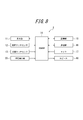
- FIG. 1 is a block diagram illustrating a schematic configuration of the electronic apparatus according to the first embodiment.
- the electronic device 1 includes a display unit 11, a front surface touch sensor 12, a back surface touch sensor 13, a control unit 14, a storage unit 15, a communication unit 16, a microphone 17, and a speaker 18.
- a display unit 11 a front surface touch sensor 12, a back surface touch sensor 13, a control unit 14, a storage unit 15, a communication unit 16, a microphone 17, and a speaker 18.
- the display unit 11 displays images such as characters, photographs, and operation objects.
- the display unit 11 is configured by using a liquid crystal panel (LCD: Liquid Crystal Display), an organic EL panel (OELD: Organic Electroluminescence Display), or the like.
- LCD Liquid Crystal Display
- OELD Organic Electroluminescence Display
- the display unit 11 displays operation objects (objects) for performing each operation such as a telephone call, mail, Internet communication, and camera shooting.
- the surface touch sensor 12 detects a finger contact or release of contact on the input surface of the surface touch sensor 12. Then, the surface touch sensor 12 detects a contact position with respect to the input surface, and outputs a signal indicating the detected contact position to the control unit 14.
- the front surface touch sensor 12 is made of a transparent member, and is superposed on the front surface of the display unit 11. The user visually recognizes the image on the display unit 11 via the transparent surface touch sensor 12 and operates the surface touch sensor 12 at the display position of the operation object displayed on the display unit 11 to perform predetermined processing on the electronic device 1. Is executed.
- the operation of the touch sensor refers to all operations such as touch, tap, double tap, and flick that make a finger contact the touch sensor.
- control unit 14 When the control unit 14 detects an operation of the surface touch sensor 12 based on a signal input from the surface touch sensor 12, the control unit 14 performs control according to the operation object displayed at the contact position. Further, the control unit 14 can scroll the screen when the surface touch sensor 12 detects a flick operation.
- the storage unit 15 can be composed of a semiconductor memory or the like, and stores various information, a program for operating the electronic device 1, and the like, and also functions as a work memory.
- the communication unit 16 enables wireless communication with a base station or other communication device.
- Speaker 18 outputs sounds such as voice, music, and ringtone.
- FIG. 2 is a diagram illustrating an example of a mounting structure of the electronic device 1 according to the first embodiment.
- 2 (a) is a front view
- FIG. 2 (b) is a cross-sectional view along the line AA in FIG. 2 (a)
- FIG. 2 (c) is a rear view.
- the display unit 11 the front surface touch sensor 12, the rear surface touch sensor 13, and the bonding member 40 is omitted.
- the electronic device 1 can include elements such as a control unit 14, a substrate, and various components.
- the microphone 17 is disposed below the surface touch sensor 12, and the speaker 18 is disposed above the surface touch sensor 12.
- the display unit 11 is disposed inside the housing 10.
- the display unit 11 may be adhered to the back surface of the front surface touch sensor 12, fixed directly to the inside of the housing 10, or fixed to a substrate or a display unit holder disposed inside the housing 10. Also good.
- the display unit 11 is bonded to the surface touch sensor 12 via the bonding member 40.
- the bonding member 40 is a thermosetting or ultraviolet curable adhesive, a double-sided tape, or the like, and may be an optical elastic resin that is a colorless and transparent acrylic ultraviolet curable adhesive, for example.
- the back touch sensor 13 is disposed on the back surface 10b of the housing 10 and supported by the housing 10 so as to include a range that can be contacted with an index finger when the electronic device 1 is held with one hand.
- the back surface touch sensor 13 is disposed on the top of the back surface 10 b of the housing 10.
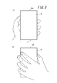
- FIG. 3 is a diagram illustrating a state where the user holds the electronic device 1 with the left hand.
- 3A is a view seen from the front side
- FIG. 3B is a view seen from the back side.
- the index finger is positioned on the back touch sensor 13. Therefore, the user can easily operate the back touch sensor 13 (touch, tap, double tap, flick, etc.) by bending the index finger without moving other fingers.
- the back touch sensor 13 is limited to a position where the index finger can contact, but may be disposed over a wider range.
- the electronic device 1 prevents unnecessary screen scrolling when canceling an operation object selected by the user by mistake. For this reason, when the electronic device 1 detects a flick operation under a predetermined condition, the electronic device 1 executes processing for canceling the flick operation.
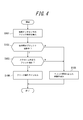
- FIG. 4 is a flowchart showing processing of the electronic device 1 related to the first cancel operation.
- the controller 14 detects a flick operation on the surface touch sensor 12 based on a signal input from the surface touch sensor 12 (step S101)
- the control unit 14 determines whether an operation object is being selected (step S102).
- the control unit 14 detects whether or not the flick operation is a flick operation that involves scrolling the screen (step S103).
- control unit 14 When the control unit 14 detects a flick operation that involves scrolling the screen while the operation object is selected (Yes in step S103), the control unit 14 cancels the flick operation and does not scroll the screen (step S104).
- the control unit 14 responds to the flick operation when the operation object is not selected when the flick operation is detected (No in step S102) or when the flick operation does not involve scrolling the screen (No in step S103). Control is executed (step S105).
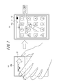
- FIG. 5 is a diagram for explaining the processing of the electronic device related to the first cancel operation.
- the user erroneously selects the icon H instead of the icon G, and performs an operation of sliding the finger leftward to cancel the selection.
- the control unit 14 cancels the flick operation and scrolls the screen because the icon H as the operation object is selected even if the finger slide is detected as a flick operation with screen scroll. Absent.
- the control unit 14 cancels the flick operation if the flick operation is accompanied by scrolling the screen. To do. Thereby, it is possible to prevent unnecessary screen scrolling related to cancellation of object selection. That is, after canceling the object selection, the user can select the correct operation object from the screen as it is, and the operability of the electronic device can be improved.
- the second canceling operation is to cancel the flick operation to the front surface touch sensor 12 performed within a predetermined time after the screen is scrolled by the back surface touch sensor 13.
- FIG. 6 is a flowchart showing processing of the electronic device 1 related to the second cancel operation.
- the control unit 14 detects a flick operation to the surface touch sensor 12 based on a signal input from the surface touch sensor 12 (step S201)
- the control unit 14 determines whether the screen scrolling by the back surface touch sensor 13 is performed within a predetermined time. (Step S202).
- the control unit 14 cancels the flick operation (Step S203).
- the control part 14 performs control according to flick operation, when the screen scroll by the back surface touch sensor 13 is not performed within predetermined time (No of step S202) (step S204).
- FIG. 7 is a diagram for explaining processing of the electronic device related to the second cancel operation.
- FIG. 7A is a diagram illustrating screen scrolling by a flick operation on the back touch sensor 13.
- the control unit 14 cancels the flick operation even if the flick operation to the front touch sensor 12 is detected within a predetermined time from the screen scrolling by the back touch sensor 13. Does not scroll the screen.
- control unit 14 cancels the flick operation when the flick operation is performed by operating the front surface touch sensor 12 within a predetermined time after scrolling the screen by operating the rear surface touch sensor 13.
- the control unit 14 cancels the flick operation when the flick operation is performed by operating the front surface touch sensor 12 within a predetermined time after scrolling the screen by operating the rear surface touch sensor 13.
- FIG. 8 is a block diagram showing a schematic configuration of an electronic apparatus according to the second embodiment of the present invention.
- the electronic device 2 according to the second embodiment further includes a press detection unit 20 as compared with the electronic device 1 according to the first embodiment. Since other configurations are the same as those of the first embodiment, the same reference numerals are given and description thereof is omitted.
- the press detection unit 20 detects a press when the user performs an operation on the back touch sensor 13, and outputs data based on the press to the control unit 14.
- the press detection unit 20 is configured using, for example, a strain gauge sensor or a piezoelectric element whose physical or electrical characteristics (strain, resistance, voltage, etc.) change according to the press.
- the piezoelectric element of the pressure detection unit 20 has a load (force) magnitude (or a load magnitude) due to the pressure applied to the back touch sensor 13 changed.
- the voltage value data based on the pressure
- the data based on the pressure may be the magnitude of the load due to the pressure, the power value, the resistance value, or the like instead of the voltage value.
- the press detection unit 20 may detect the press when the user performs an operation on the surface touch sensor 12 in the same manner.
- the press detection part 20 can be comprised according to a contact detection system.
- a contact detection method is a resistance film method
- a strain gauge sensor, a piezoelectric element, or the like can be obtained by associating the magnitude of the resistance according to the size of the contact area with the load of pressing against the touch surface of the touch sensor.
- the press detection unit 20 can be configured without using it.
- the capacitance can be configured without using a strain gauge sensor, a piezoelectric element, or the like by associating the magnitude of the capacitance with a load applied to the touch sensor.
- FIG. 9 is a diagram illustrating an example of a mounting structure of the electronic device 2 according to the second embodiment.
- 9A is a front view
- FIG. 9B is a cross-sectional view taken along line AA in FIG. 9A
- FIG. 9C is a rear view.
- FIG. 9 further illustrates piezoelectric elements 21 to 24 constituting the pressure detection unit 20 with respect to the mounting structure of the electronic device 1 shown in FIG. Note that the number and arrangement position of the piezoelectric elements are not limited to the illustrated example.
- the press detection unit 20 includes a first piezoelectric element 21, a second piezoelectric element 22, a third piezoelectric element 23, and a fourth piezoelectric element 24, and the first piezoelectric element 21 and the second piezoelectric element 24.
- the element 22 detects a pressure when the user performs an operation on the back surface touch sensor 13, and the third piezoelectric element 23 and the fourth piezoelectric element 24 detect when the user performs an operation on the surface touch sensor 12. Detects pressing.
- the cancel operation of the electronic device 2 according to the second embodiment is performed according to the flowcharts shown in FIGS. 4 and 6 as in the first embodiment.
- the control part 14 can use the data based on the press with respect to the surface touch sensor 12 acquired from the press detection part 20 regarding the detection of the flick operation of step S101 and step S201. That is, the control unit 14 can detect an operation on the front surface touch sensor 12 as a flick operation when the data acquired from the pressure detection unit 20 satisfies a predetermined threshold.
- the electronic device 2 further includes the press detection unit 20. Therefore, it is possible for the electronic device 2 to prevent the user from determining that an operation has been performed simply by lightly touching another object.
- the finger touches the touch sensors on the front and back surfaces, but by detecting the press by the press detection unit 20, the user has operated it even though the operation is not intended. It can prevent misjudging it as a thing.
- FIG. 10 is a block diagram showing a schematic configuration of an electronic apparatus according to the third embodiment of the present invention.
- the electronic device 3 according to the third embodiment further includes a tactile sensation providing unit 30 as compared with the electronic device 2 according to the second embodiment. Since other configurations are the same as those of the second embodiment, the same reference numerals are given and description thereof is omitted.
- the tactile sensation providing unit 30 is configured using a piezoelectric element, an ultrasonic vibrator, a vibration motor (eccentric motor), or the like, and a user who presses the back touch sensor 13 by generating vibration according to a predetermined vibration pattern.
- the tactile sensation is presented to the user's finger, and the user is sensibly notified that the rear touch sensor 13 has been operated.
- the tactile sensation providing unit 30 presents a tactile sensation to the user's finger pressing the back touch sensor 13 by controlling the charge of the film pasted on the back touch sensor 13 without using mechanical vibration. May be.
- the tactile sensation providing unit 30 may generate vibrations in the same manner for the surface touch sensor 12 so as to present a tactile sensation to the user's finger pressing the surface touch sensor 12. .
- the tactile sensation providing unit 30 can be configured integrally with the press detection unit 20.
- the piezoelectric elements can be shared. This is because the piezoelectric element generates a voltage when pressure is applied and deforms when the voltage is applied.
- An example of the mounting structure in this case is as shown in FIG.
- the control unit 14 performs a predetermined process when the voltage value of the piezoelectric element satisfies a predetermined threshold, You may make it generate a vibration by driving.
- the time when the voltage value of the piezoelectric element satisfies a predetermined threshold value may be when the voltage value reaches a predetermined reference value or when the voltage value exceeds a predetermined reference value. However, it may be when a voltage value equal to a predetermined reference value is detected.
- the electronic device 3 further includes the tactile sensation providing unit 30 and generates a predetermined vibration based on the drive signal supplied from the control unit 14. Therefore, when the user operates the back surface touch sensor 13 (and the front surface touch sensor 12), the electronic device 3 can sensibly notify the user that the intended operation has been performed.
- processors that execute logic blocks, program modules, etc. include, for example, one or more microprocessors, CPU (Central Processing Unit), ASIC (Application Specific Integrated Circuit), DSP (Digital Signal Processor), PLD (Programmable Logic (Device), FPGA (Field Programmable Gate Array), processor, controller, microcontroller, microprocessor, electronics, other devices designed to perform the functions described here, and / or any combination of these It is.
- the embodiments shown here are implemented, for example, by hardware, software, firmware, middleware, microcode, or any combination thereof.
- the instructions may be program code or code segments for performing the necessary tasks.
- the instructions can then be stored on a machine-readable non-transitory storage medium or other medium.
- a code segment may represent any combination of procedures, functions, subprograms, programs, routines, subroutines, modules, software packages, classes or instructions, data structures or program statements.
- a code segment transmits and / or receives information, data arguments, variables or stored contents with other code segments or hardware circuits, thereby connecting the code segments with other code segments or hardware circuits .
Landscapes
- Engineering & Computer Science (AREA)
- Theoretical Computer Science (AREA)
- General Engineering & Computer Science (AREA)
- Human Computer Interaction (AREA)
- Physics & Mathematics (AREA)
- General Physics & Mathematics (AREA)
- Computer Hardware Design (AREA)
- Signal Processing (AREA)
- User Interface Of Digital Computer (AREA)
Abstract
電子機器(1)は、表面にタッチセンサ(12)を有し、前記表面のタッチセンサへ(12)の操作により、オブジェクトが選択されたままフリック操作が行われた場合、画面のスクロールを伴うフリック操作であれば、当該フリック操作をキャンセルする制御部(14)を備える。
Description
本出願は、2013年11月28日に日本国に特許出願された特願2013-246409の優先権を主張するものであり、この先の出願の開示全体をここに参照のために取り込む。
本発明は、タッチセンサを有する電子機器に関する。
近年、ユーザによる接触を検知するタッチセンサを備えた携帯電話等の電子機器が増加している。接触の検出方式は、抵抗膜方式、静電容量方式等、種々の検出方式が知られており、いずれの方式もユーザの指やスタイラスペン等による接触物の接触を検出する。
また、表面に加え、背面にもタッチセンサを有する電子機器が知られている。例えば、特許文献1には、表面および背面にそれぞれ2つのタッチセンサを備え、使用状態に対応付けられた所定の対応関係に基づいて、第1背面または第2背面に対する入力を、第1表面または第2表面に対する入力として受け付けることにより、利便性を高めることが可能な携帯端末が記載されている。
タッチセンサを備えるスマートフォンなどの電子機器では、一般に、表示されているオブジェクト(アプリケーションアイコン、ブラウザ等のリンク先)に対して指で触れることで選択、指を離すことで決定がなされる。通常、これらのオブジェクトの選択、決定は一連のタップ動作(画面をポンと軽く押す動作)として行われる。ここで、ユーザは、オブジェクトの選択ミスに気付いた場合、指を離す前に、誤って選択したオブジェクトの範囲外に指をスライドさせることでオブジェクトの選択をキャンセルすることができる。
ここで、オブジェクト選択をキャンセルするための指のスライドが、誤って画面スクロールを伴うフリック操作(画面上で指を払う(スライドさせる)動作)として検出されることがある。図11は、誤って検出されたフリック操作により生じる不要な画面スクロールを示す図である。図11(a)では、ユーザがアイコンGの代わりにアイコンHを誤って選択し、選択キャンセルのために指を左方向にスライドさせる動作を行う。このとき、電子機器が指のスライドをフリック操作として検出すると、図11(b)に示す通り画面のスクロールが行われてしまう。このため、ユーザが目的のオブジェクトであるアイコンGを選択するためには、元の画面に戻すための操作が必要になってしまうという問題があった。
かかる事情に鑑みてなされた本発明の目的は、オブジェクト選択のキャンセルに係る不要な画面スクロールを防止することが可能な電子機器を提供することにある。
上述した諸課題を解決すべく、本発明に係る電子機器は、
表面にタッチセンサを有する電子機器であって、
前記表面のタッチセンサへの操作により、オブジェクトが選択されたままフリック操作が行われた場合、画面のスクロールを伴うフリック操作であれば、当該フリック操作をキャンセルする制御部を備えることを特徴とする。
表面にタッチセンサを有する電子機器であって、
前記表面のタッチセンサへの操作により、オブジェクトが選択されたままフリック操作が行われた場合、画面のスクロールを伴うフリック操作であれば、当該フリック操作をキャンセルする制御部を備えることを特徴とする。
さらに、上述した諸課題を解決すべく、本発明に係る電子機器は、
表面および背面にタッチセンサを有する電子機器であって、
前記背面のタッチセンサへの操作により画面をスクロールした後、所定時間内に前記表面のタッチセンサへの操作によりフリック操作が行われた場合、当該フリック操作をキャンセルする制御部を備えることを特徴とする。
表面および背面にタッチセンサを有する電子機器であって、
前記背面のタッチセンサへの操作により画面をスクロールした後、所定時間内に前記表面のタッチセンサへの操作によりフリック操作が行われた場合、当該フリック操作をキャンセルする制御部を備えることを特徴とする。
本発明によれば、オブジェクト選択のキャンセルに係る不要な画面スクロールを防止することが可能となる。
以降、諸図面を参照しながら、本発明の実施態様を詳細に説明する。
[第1の実施形態]
図1は、第1の実施形態に係る電子機器の概略構成を示すブロック図である。図1に示す例では、電子機器1は、表示部11と、表面タッチセンサ12と、背面タッチセンサ13と、制御部14と、記憶部15と、通信部16と、マイク17と、スピーカ18とを備える。
図1は、第1の実施形態に係る電子機器の概略構成を示すブロック図である。図1に示す例では、電子機器1は、表示部11と、表面タッチセンサ12と、背面タッチセンサ13と、制御部14と、記憶部15と、通信部16と、マイク17と、スピーカ18とを備える。
表示部11は、文字、写真、操作用オブジェクト等の画像を表示する。表示部11は、液晶パネル(LCD:Liquid Crystal Display)や有機ELパネル(OELD:OrganicElectroluminescence Display)等を用いて構成される。例えばホーム画面では、表示部11は、電話、メール、インターネット通信、カメラ撮影等の各操作を行うための操作用オブジェクト(オブジェクト)を表示させる。
表面タッチセンサ12は、表面タッチセンサ12の入力面において、指の接触または接触の解除を検出する。そして、表面タッチセンサ12は、入力面に対する接触位置を検出し、検出した接触位置を示す信号を制御部14へ出力する。表面タッチセンサ12は透明な部材で構成され、表示部11の前面に重畳配置される。ユーザは透明な表面タッチセンサ12を介して表示部11の画像を視認し、表示部11が表示する操作用オブジェクトの表示位置の表面タッチセンサ12を操作することにより、電子機器1に所定の処理を実行させる。ここで、タッチセンサの操作とは、タッチ、タップ、ダブルタップ、フリック等の、指をタッチセンサに接触させるあらゆる操作をいう。
背面タッチセンサ13は、電子機器1を操作する際の操作性を向上させるために電子機器1の背面に配置され、背面タッチセンサ13の入力面において、指による接触または接触の解除を検出し、検出結果を制御部14へ出力する。表面タッチセンサ12および背面タッチセンサ13は、例えば、抵抗膜方式、静電容量方式等の周知の方式で実現される。
制御部14は、表面タッチセンサ12から入力される信号により表面タッチセンサ12の操作を検出すると、接触位置に表示されている操作用オブジェクトに応じた制御を行う。また、制御部14は、表面タッチセンサ12によりフリック操作を検出すると、画面のスクロールを行うことができる。
制御部14は、背面タッチセンサ13から入力される信号により背面タッチセンサ13の操作を検出すると、入力操作に応じた制御を行う。制御部14は、背面タッチセンサ13によりフリック操作を検出すると、画面のスクロールを行うことができる。
記憶部15は、半導体メモリ等で構成することができ、各種情報や電子機器1を動作させるためのプログラム等を記憶するとともに、ワークメモリとしても機能する。
通信部16は、基地局または他の通信機器と無線により通信することを可能にする。
マイク17は、ユーザの発話等の周囲の音を集音する。マイク17が集音した音は、電気信号に変換して制御部14に送られる。
スピーカ18は、音声、音楽、着信音等の音を出力する。
図2は、第1の実施形態に係る電子機器1の実装構造の一例を示す図である。図2(a)は正面図であり、図2(b)は図2(a)におけるA-A線に沿った断面図であり、図2(c)は背面図である。
なお、図2においては、筐体10、表示部11、表面タッチセンサ12、背面タッチセンサ13、および接合部材40以外の要素の図示は省略している。電子機器1は、図2に示した以外にも、例えば、制御部14、基板、及び各種部品等の要素を備えることができる。また、典型的にはマイク17は表面タッチセンサ12の下部に配置され、スピーカ18は表面タッチセンサ12の上部に配置される。
図2に示すように、表面タッチセンサ12は筐体10(例えば、金属や樹脂のケース)の表面10aに配置され、筐体10に支持される。
表示部11は、筐体10の内部に配置される。例えば、表示部11を表面タッチセンサ12の裏面に接着してもよいし、筐体10の内部に直接固定するか、筐体10の内部配置される基板または表示部用ホルダ等に固定してもよい。図2では、表示部11は、接合部材40を介して表面タッチセンサ12に接着されている。図2(b)に示すように、表示部11を、表面タッチセンサ12の裏面側に配置すれば、表面タッチセンサ12および表示部11によりタッチパネルを構成する際に、表示部11に自由なユーザインタフェースを表示して、ユーザの操作を表面タッチセンサ12により検出することができる。なお、接合部材40は、熱硬化性あるいは紫外線硬化性等を有する接着剤や両面テープ等であり、例えば無色透明のアクリル系紫外線硬化型接着剤である光学弾性樹脂でもよい。
背面タッチセンサ13は、電子機器1を片手で保持した際に、人差し指で接触可能な範囲を含むように、筐体10の背面10bに配置され、筐体10に支持される。例えば、図2(b)(c)に示すように、背面タッチセンサ13は筐体10の背面10bの上部に配置される。
図3は、ユーザが電子機器1を左手で保持した状態を示す図である。図3(a)は表面側から見た図であり、図3(b)は背面側から見た図である。図3(b)に示すように電子機器1を左手で保持すると、人差し指は背面タッチセンサ13上に位置する。よって、ユーザは人差し指を折り曲げるだけで他の指は動かすことなく容易に背面タッチセンサ13を操作(タッチ、タップ、ダブルタップ、フリック等)することができる。なお、本実施形態では、背面タッチセンサ13を人差し指が接触可能な位置に限定して配置しているが、より広範囲にわたって配置させてもよい。
これ以降、本発明に係る電子機器1による処理を説明する。電子機器1は、ユーザが誤って選択した操作用オブジェクトをキャンセルする際の不要な画面スクロールを防止するものである。このため、電子機器1は、所定の条件下でフリック操作を検出した場合、係るフリック操作をキャンセルする処理を実行する。
(第1のキャンセル動作)
第1のキャンセル動作は、操作用オブジェクト選択中に画面のスクロールを伴うフリック操作が行われた場合、かかるフリック操作は操作用オブジェクトの選択をキャンセルするためのものであるとして、フリック操作をキャンセルするものである。図4は、第1のキャンセル動作に係る電子機器1の処理を示すフローチャートである。制御部14は、表面タッチセンサ12から入力される信号により表面タッチセンサ12へのフリック操作を検出すると(ステップS101)、操作用オブジェクトが選択中であるか否かを判定する(ステップS102)。制御部14は、操作用オブジェクト選択中(ステップS102のYes)である場合、当該フリック操作が画面のスクロールを伴うフリック操作か否かを検出する(ステップS103)。制御部14は、操作用オブジェクト選択中に画面のスクロールを伴うフリック操作を検出した場合(ステップS103のYes)、当該フリック操作をキャンセルし、画面のスクロールは行わない(ステップS104)。なお、制御部14は、フリック操作検出時に操作用オブジェクトが選択されていないか(ステップS102のNo)、フリック操作が画面のスクロールを伴うものではない場合(ステップS103のNo)、フリック操作に応じた制御を実行する(ステップS105)。
第1のキャンセル動作は、操作用オブジェクト選択中に画面のスクロールを伴うフリック操作が行われた場合、かかるフリック操作は操作用オブジェクトの選択をキャンセルするためのものであるとして、フリック操作をキャンセルするものである。図4は、第1のキャンセル動作に係る電子機器1の処理を示すフローチャートである。制御部14は、表面タッチセンサ12から入力される信号により表面タッチセンサ12へのフリック操作を検出すると(ステップS101)、操作用オブジェクトが選択中であるか否かを判定する(ステップS102)。制御部14は、操作用オブジェクト選択中(ステップS102のYes)である場合、当該フリック操作が画面のスクロールを伴うフリック操作か否かを検出する(ステップS103)。制御部14は、操作用オブジェクト選択中に画面のスクロールを伴うフリック操作を検出した場合(ステップS103のYes)、当該フリック操作をキャンセルし、画面のスクロールは行わない(ステップS104)。なお、制御部14は、フリック操作検出時に操作用オブジェクトが選択されていないか(ステップS102のNo)、フリック操作が画面のスクロールを伴うものではない場合(ステップS103のNo)、フリック操作に応じた制御を実行する(ステップS105)。
図5は、第1のキャンセル動作に係る電子機器の処理を説明する図である。図5では、ユーザがアイコンGの代わりにアイコンHを誤って選択し、選択キャンセルのために指を左方向にスライドさせる動作を行う。このとき、制御部14は、指のスライドを画面スクロールを伴うフリック操作として検出しても、操作用オブジェクトであるアイコンHが選択中であるため、当該フリック操作をキャンセルし、画面のスクロールは行わない。
このように、制御部14は、表面タッチセンサ12への操作により、操作用オブジェクトが選択されたままフリック操作が行われた場合、画面のスクロールを伴うフリック操作であれば、当該フリック操作をキャンセルする。これにより、オブジェクト選択のキャンセルに係る不要な画面スクロールを防止することが可能となる。すなわち、ユーザはオブジェクト選択のキャンセル後、そのままの画面から正しい操作用オブジェクトを選択することができ、電子機器の操作性を向上させることが可能となる。
(第2のキャンセル動作)
第2のキャンセル動作は、背面タッチセンサ13により画面スクロールを行ってから所定時間内に行われた表面タッチセンサ12へのフリック操作をキャンセルするものである。図6は、第2のキャンセル動作に係る電子機器1の処理を示すフローチャートである。制御部14は、表面タッチセンサ12から入力される信号により表面タッチセンサ12へのフリック操作を検出すると(ステップS201)、背面タッチセンサ13による画面スクロールが所定時間以内に行われたか否かを判定する(ステップS202)。制御部14は、所定時間内に背面タッチセンサ13による画面スクロールが行われている場合(ステップS202のYes)、フリック操作をキャンセルする(ステップS203)。なお、制御部14は、所定時間内に背面タッチセンサ13による画面スクロールが行われていない場合(ステップS202のNo)、フリック操作に応じた制御を行う(ステップS204)。
第2のキャンセル動作は、背面タッチセンサ13により画面スクロールを行ってから所定時間内に行われた表面タッチセンサ12へのフリック操作をキャンセルするものである。図6は、第2のキャンセル動作に係る電子機器1の処理を示すフローチャートである。制御部14は、表面タッチセンサ12から入力される信号により表面タッチセンサ12へのフリック操作を検出すると(ステップS201)、背面タッチセンサ13による画面スクロールが所定時間以内に行われたか否かを判定する(ステップS202)。制御部14は、所定時間内に背面タッチセンサ13による画面スクロールが行われている場合(ステップS202のYes)、フリック操作をキャンセルする(ステップS203)。なお、制御部14は、所定時間内に背面タッチセンサ13による画面スクロールが行われていない場合(ステップS202のNo)、フリック操作に応じた制御を行う(ステップS204)。
図7は、第2のキャンセル動作に係る電子機器の処理を説明する図である。図7(a)は、背面タッチセンサ13へのフリック操作による画面スクロールを示す図である。この場合、図7(b)に示す通り、制御部14は、背面タッチセンサ13による画面スクロールから所定時間以内に表面タッチセンサ12へのフリック操作を検出しても、当該フリック操作をキャンセルし、画面のスクロールは行わない。
このように、制御部14は、背面タッチセンサ13への操作により画面をスクロールした後、所定時間内に表面タッチセンサ12への操作によりフリック操作が行われた場合、当該フリック操作をキャンセルする。これにより、オブジェクト選択のキャンセルに係る不要な画面スクロールを防止することが可能となる。すなわち、ユーザはオブジェクト選択のキャンセル後、そのままの画面から正しい操作用オブジェクトを選択することができ、電子機器の操作性を向上させることが可能となる。
[第2の実施形態]
次に、本発明の第2の実施形態について説明する。図8は、本発明の第2の実施形態に係る電子機器の概略構成を示すブロック図である。第2の実施形態に係る電子機器2は、第1の実施形態に係る電子機器1と比較して、更に押圧検出部20を備える。その他の構成については第1の実施形態と同一であるため、同一の参照番号を付して説明を省略する。
次に、本発明の第2の実施形態について説明する。図8は、本発明の第2の実施形態に係る電子機器の概略構成を示すブロック図である。第2の実施形態に係る電子機器2は、第1の実施形態に係る電子機器1と比較して、更に押圧検出部20を備える。その他の構成については第1の実施形態と同一であるため、同一の参照番号を付して説明を省略する。
押圧検出部20は、背面タッチセンサ13に対してユーザが操作を行う際の押圧を検出し、押圧に基づくデータを制御部14に出力する。押圧検出部20は、例えば、押圧に応じて物理的または電気的な特性(歪み、抵抗、電圧等)が変化する歪みゲージセンサや圧電素子等を用いて構成される。押圧検出部20が、例えば圧電素子を用いて構成された場合、押圧検出部20の圧電素子は、背面タッチセンサ13に対する押圧による荷重(力)の大きさ(または、荷重の大きさが変化する速さ(加速度))に応じて、電気的な特性である電圧値(押圧に基づくデータ)が変化する。なお、押圧に基づくデータは、電圧値の代わりに、押圧による荷重の大きさ、電力値、抵抗値等でもよい。
また、押圧検出部20は、表面タッチセンサ12に対してユーザが操作を行う際の押圧を同様にして検出してもよい。
制御部14は、押圧検出部20から背面タッチセンサ13(および表面タッチセンサ12)に対する押圧に基づくデータを取得する。そして、制御部14は、押圧に基づくデータが所定の閾値以上である場合に、所定の操作が行われたと判断し、操作内容に応じて例えばアプリケーションに基づく等して、所定の処理を行うように制御する。
また、押圧検出部20は、接触検出方式に応じて構成することができる。例えば、接触検出方式が抵抗膜方式の場合には、接触面積の大きさに応じた抵抗の大きさを、タッチセンサのタッチ面に対する押圧の荷重に対応付けることにより、歪みゲージセンサや圧電素子等を用いることなく押圧検出部20を構成することができる。あるいは、タッチセンサが静電容量方式の場合には、静電容量の大きさを、タッチセンサに対する押圧の荷重に対応付けることにより、歪みゲージセンサや圧電素子等を用いることなく構成することができる。
図9は、第2の実施形態に係る電子機器2の実装構造の一例を示す図である。図9(a)は正面図であり、図9(b)は図9(a)におけるA-A線に沿った断面図であり、図9(c)は背面図である。図9は、図2に示した電子機器1の実装構造に対して、更に押圧検出部20を構成する圧電素子21~24を図示している。なお、圧電素子の個数や配置位置は、図示した例に限定されるものではない。
図9に示す例では、押圧検出部20は、第1圧電素子21、第2圧電素子22、第3圧電素子23、および第4圧電素子24を有し、第1圧電素子21および第2圧電素子22により、背面タッチセンサ13に対してユーザが操作を行う際の押圧を検出し、第3圧電素子23および第4圧電素子24により、表面タッチセンサ12に対してユーザが操作を行う際の押圧を検出する。
なお、図9(a)において、表面タッチセンサ12上において表示部11による表示を透過させる必要がない領域、すなわち、表面タッチセンサ12と表示部11とが重ならない領域は、表面タッチセンサ12の端辺付近の領域を塗装したりベゼルで覆ったりするのが好適である。このようにすれば、第3圧電素子23および第4圧電素子24等が電子機器1の外部から見えてしまうことを防ぐことができる。
第2実施形態に係る電子機器2のキャンセル動作は、第1実施形態と同様に図4、図6に示すフローチャートに沿って行われる。なお、制御部14は、ステップS101及びステップS201のフリック操作の検出に関し、押圧検出部20から取得した表面タッチセンサ12に対する押圧に基づくデータを用いることができる。即ち、制御部14は、押圧検出部20から取得したデータが所定の閾値を満たす場合に、表面タッチセンサ12への操作をフリック操作として検出することができる。
このように、第2の実施形態に係る電子機器2は、押圧検出部20を更に備える。そのため、電子機器2は、他の物体と軽く接触しただけでユーザによる操作が行われたと判断することを防止できる。特に、電子機器を保持する際には表面及び背面のタッチセンサに指が接触するが、押圧検出部20により押圧を検出することにより、ユーザが操作を意図していないのにもかかわらず操作したものと誤判断することを防止できる。
[第3の実施形態]
次に、本発明の第3の実施形態について説明する。図10は、本発明の第3の実施形態に係る電子機器の概略構成を示すブロック図である。第3の実施形態に係る電子機器3は、第2の実施形態に係る電子機器2と比較して、更に触感呈示部30を備える。その他の構成については第2の実施形態と同一であるため、同一の参照番号を付して説明を省略する。
次に、本発明の第3の実施形態について説明する。図10は、本発明の第3の実施形態に係る電子機器の概略構成を示すブロック図である。第3の実施形態に係る電子機器3は、第2の実施形態に係る電子機器2と比較して、更に触感呈示部30を備える。その他の構成については第2の実施形態と同一であるため、同一の参照番号を付して説明を省略する。
触感呈示部30は、制御部14から供給される駆動信号に基づいて所定の振動を発生する。駆動信号については、表現したいリアルなボタンが挙動する振動を、指が接触する位置において表現する駆動信号であればよい。
触感呈示部30は、圧電素子、超音波振動子、または振動モータ(偏心モータ)等を用いて構成され、所定の振動パターンによる振動を発生させることにより、背面タッチセンサ13を押圧しているユーザの指に対して触感を呈示し、ユーザに背面タッチセンサ13を操作したことを感覚的に通知する。触感呈示部30は、機械的な振動を使わずに、背面タッチセンサ13上に貼ったフィルムの電荷を制御する等により、背面タッチセンサ13を押圧しているユーザの指に対して触感を呈示してもよい。
また、触感呈示部30は、表面タッチセンサ12に対しても、同様にして振動を発生させて、表面タッチセンサ12を押圧しているユーザの指に対して触感を呈示するようにしてもよい。
なお、触感呈示部30は、押圧検出部20と一体化して構成することもできる。特に、押圧検出部20および触感呈示部30を圧電素子を用いて構成する場合は、圧電素子を共用することもできる。圧電素子は、圧力が加わると電圧を発生し、電圧が加えられると変形するためである。この場合の実装構造例は、図9に示した通りである。
押圧検出部20および触感呈示部30を圧電素子を用いて構成する場合、制御部14は、圧電素子の電圧値が所定の閾値を満たした際に、所定の処理を行うとともに、該圧電素子を駆動することにより振動を発生させるようにしてもよい。ここで、圧電素子の電圧値が所定の閾値を満たした際とは、電圧値が所定の基準値に達した際であってもよいし、電圧値が所定の基準値を超えた際でもよいし、所定の基準値と等しい電圧値が検出された際でもよい。
上述したように、第3の実施形態に係る電子機器3は、触感呈示部30を更に備え、制御部14から供給される駆動信号に基づいて所定の振動を発生する。そのため、電子機器3は、ユーザが背面タッチセンサ13(および表面タッチセンサ12)を操作した際に、意図した操作が行われたことを感覚的にユーザに通知することができる。
上述の実施形態は代表的な例として説明したが、本発明の趣旨及び範囲内で、多くの変更及び置換ができることは当業者に明らかである。したがって、本発明は、上述の実施形態によって制限するものと解するべきではなく、特許請求の範囲から逸脱することなく、種々の変形や変更が可能である。例えば、実施形態に記載の複数の構成ブロックを1つに組み合わせたり、あるいは1つの構成ブロックを分割したりすることが可能である。また、本実施形態では、種々の動作は、プログラム命令(ソフトウェア)で実装された専用回路(たとえば、特定機能を実行するために相互接続された個別の論理ゲート)や、一以上のプロセッサにより実行される論理ブロックやプログラムモジュール等により実行されることに留意されたい。論理ブロックやプログラムモジュール等を実行する一以上のプロセッサには、たとえば、一以上のマイクロプロセッサ、CPU(中央演算処理ユニット)、ASIC(Application Specific Integrated Circuit)、DSP(Digital Signal Processor)、PLD(Programmable Logic Device)、FPGA(Field Programmable Gate Array)、プロセッサ、コントローラ、マイクロコントローラ、マイクロプロセッサ、電子機器、ここに記載する機能を実行可能に設計されたその他の装置及び/またはこれらいずれかの組合せが含まれる。ここに示す実施形態は、たとえば、ハードウェア、ソフトウェア、ファームウェア、ミドルウェア、マイクロコードまたはこれらいずれかの組合せにより実装される。命令は、必要なタスクを実行するためのプログラムコードまたはコードセグメントであってもよい。そして、命令は、機械読取り可能な非一時的記憶媒体その他の媒体に格納することができる。コードセグメントは、手順、関数、サブプログラム、プログラム、ルーチン、サブルーチン、モジュール、ソフトウェアパッケージ、クラスまたは命令、データ構造もしくはプログラムステートメントのいずれかの任意の組合せを示すものであってもよい。コードセグメントは、他のコードセグメントまたはハードウェア回路と、情報、データ引数、変数または記憶内容の送信及び/または受信を行い、これにより、コードセグメントが他のコードセグメントまたはハードウェア回路と接続される。
1,2,3 電子機器
11 表示部
12 表面タッチセンサ
13 背面タッチセンサ
14 制御部
15 記憶部
16 通信部
17 マイク
18 スピーカ
20 押圧検出部
21 第1圧電素子
22 第2圧電素子
23 第3圧電素子
24 第4圧電素子
30 触感呈示部
40 接合部材
11 表示部
12 表面タッチセンサ
13 背面タッチセンサ
14 制御部
15 記憶部
16 通信部
17 マイク
18 スピーカ
20 押圧検出部
21 第1圧電素子
22 第2圧電素子
23 第3圧電素子
24 第4圧電素子
30 触感呈示部
40 接合部材
Claims (2)
- 表面にタッチセンサを有する電子機器であって、
前記表面のタッチセンサへの操作により、オブジェクトが選択されたままフリック操作が行われた場合、画面のスクロールを伴うフリック操作であれば、当該フリック操作をキャンセルする制御部を備えることを特徴とする電子機器。 - 表面および背面にタッチセンサを有する電子機器であって、
前記背面のタッチセンサへの操作により画面をスクロールした後、所定時間内に前記表面のタッチセンサへの操作によりフリック操作が行われた場合、当該フリック操作をキャンセルする制御部を備えることを特徴とする電子機器。
Priority Applications (2)
| Application Number | Priority Date | Filing Date | Title |
|---|---|---|---|
| US15/100,170 US20170038963A1 (en) | 2013-11-28 | 2014-11-26 | Electronic device |
| US16/851,040 US20200241743A1 (en) | 2013-11-28 | 2020-04-16 | Electronic device with flick operation and scrolling |
Applications Claiming Priority (2)
| Application Number | Priority Date | Filing Date | Title |
|---|---|---|---|
| JP2013246409A JP6062351B2 (ja) | 2013-11-28 | 2013-11-28 | 電子機器 |
| JP2013-246409 | 2013-11-28 |
Related Child Applications (2)
| Application Number | Title | Priority Date | Filing Date |
|---|---|---|---|
| US15/100,170 A-371-Of-International US20170038963A1 (en) | 2013-11-28 | 2014-11-26 | Electronic device |
| US16/851,040 Division US20200241743A1 (en) | 2013-11-28 | 2020-04-16 | Electronic device with flick operation and scrolling |
Publications (1)
| Publication Number | Publication Date |
|---|---|
| WO2015079686A1 true WO2015079686A1 (ja) | 2015-06-04 |
Family
ID=53198650
Family Applications (1)
| Application Number | Title | Priority Date | Filing Date |
|---|---|---|---|
| PCT/JP2014/005921 Ceased WO2015079686A1 (ja) | 2013-11-28 | 2014-11-26 | 電子機器 |
Country Status (3)
| Country | Link |
|---|---|
| US (2) | US20170038963A1 (ja) |
| JP (1) | JP6062351B2 (ja) |
| WO (1) | WO2015079686A1 (ja) |
Families Citing this family (1)
| Publication number | Priority date | Publication date | Assignee | Title |
|---|---|---|---|---|
| CN106919282A (zh) * | 2017-02-10 | 2017-07-04 | 南昌欧菲显示科技有限公司 | 触觉反馈显示屏 |
Citations (1)
| Publication number | Priority date | Publication date | Assignee | Title |
|---|---|---|---|---|
| JP2013105461A (ja) * | 2011-11-16 | 2013-05-30 | Canon Inc | 情報処理装置及びその制御方法 |
Family Cites Families (19)
| Publication number | Priority date | Publication date | Assignee | Title |
|---|---|---|---|---|
| US9292111B2 (en) * | 1998-01-26 | 2016-03-22 | Apple Inc. | Gesturing with a multipoint sensing device |
| US7761814B2 (en) * | 2004-09-13 | 2010-07-20 | Microsoft Corporation | Flick gesture |
| US20090278806A1 (en) * | 2008-05-06 | 2009-11-12 | Matias Gonzalo Duarte | Extended touch-sensitive control area for electronic device |
| US8285499B2 (en) * | 2009-03-16 | 2012-10-09 | Apple Inc. | Event recognition |
| US8497884B2 (en) * | 2009-07-20 | 2013-07-30 | Motorola Mobility Llc | Electronic device and method for manipulating graphic user interface elements |
| JP5523090B2 (ja) * | 2009-12-25 | 2014-06-18 | キヤノン株式会社 | 入力装置、入力装置の制御方法、プログラムおよび記憶媒体 |
| JP5664249B2 (ja) * | 2011-01-06 | 2015-02-04 | ソニー株式会社 | 情報処理装置、情報処理方法及び情報処理プログラム |
| JP5816834B2 (ja) * | 2011-03-22 | 2015-11-18 | パナソニックIpマネジメント株式会社 | 入力装置、および入力方法 |
| JP5716502B2 (ja) * | 2011-04-06 | 2015-05-13 | ソニー株式会社 | 情報処理装置、情報処理方法およびコンピュータプログラム |
| JP5829982B2 (ja) * | 2011-06-28 | 2015-12-09 | 京セラ株式会社 | 電子機器、報知制御方法および制御プログラム |
| US8775966B2 (en) * | 2011-06-29 | 2014-07-08 | Motorola Mobility Llc | Electronic device and method with dual mode rear TouchPad |
| EP3457672B1 (en) * | 2011-09-27 | 2019-11-20 | Nec Corporation | Portable electronic device, touch operation processing method, and program |
| WO2013050799A1 (en) * | 2011-10-03 | 2013-04-11 | Sony Ericsson Mobile Communications Ab | Electronic device with touch-based deactivation of touch input signaling |
| KR101710418B1 (ko) * | 2011-12-19 | 2017-02-28 | 삼성전자주식회사 | 휴대 단말기의 멀티 터치 인터렉션 제공 방법 및 장치 |
| JP5876747B2 (ja) * | 2012-02-23 | 2016-03-02 | シャープ株式会社 | 通信端末装置、制御方法、プログラム、及び、記録媒体 |
| US9377946B2 (en) * | 2012-03-19 | 2016-06-28 | Panasonic Intellectual Property Management Co., Ltd. | On-board apparatus |
| JP5828297B2 (ja) * | 2012-04-24 | 2015-12-02 | コニカミノルタ株式会社 | 情報処理装置、プログラム |
| KR101398141B1 (ko) * | 2013-02-08 | 2014-05-20 | 엘지전자 주식회사 | 이동 단말기 |
| KR102120651B1 (ko) * | 2013-05-30 | 2020-06-09 | 삼성전자 주식회사 | 터치스크린을 구비하는 디바이스에서 화면 표시 방법 및 장치 |
-
2013
- 2013-11-28 JP JP2013246409A patent/JP6062351B2/ja active Active
-
2014
- 2014-11-26 US US15/100,170 patent/US20170038963A1/en not_active Abandoned
- 2014-11-26 WO PCT/JP2014/005921 patent/WO2015079686A1/ja not_active Ceased
-
2020
- 2020-04-16 US US16/851,040 patent/US20200241743A1/en not_active Abandoned
Patent Citations (1)
| Publication number | Priority date | Publication date | Assignee | Title |
|---|---|---|---|---|
| JP2013105461A (ja) * | 2011-11-16 | 2013-05-30 | Canon Inc | 情報処理装置及びその制御方法 |
Non-Patent Citations (1)
| Title |
|---|
| MASAYUKI AKAMATSU: "1.6 Outlet ya Action no Setsuzoku, iPhone SDK no Kyokasho Cocoa Touch Programming", SAISHO NO IPPO, 25 March 2009 (2009-03-25), KAZUKUNI SAITO, pages 209 - 211 * |
Also Published As
| Publication number | Publication date |
|---|---|
| US20200241743A1 (en) | 2020-07-30 |
| US20170038963A1 (en) | 2017-02-09 |
| JP6062351B2 (ja) | 2017-01-18 |
| JP2015106171A (ja) | 2015-06-08 |
Similar Documents
| Publication | Publication Date | Title |
|---|---|---|
| US10627947B2 (en) | Electronic device | |
| JP6246640B2 (ja) | 電子機器 | |
| US10353567B2 (en) | Electronic device | |
| US10795492B2 (en) | Input device and method for controlling input device | |
| JPWO2013001775A1 (ja) | 電子機器 | |
| JPWO2013061605A1 (ja) | 触感呈示装置 | |
| US10996712B2 (en) | Electronic device | |
| US10444803B2 (en) | Electronic device | |
| US10845914B2 (en) | Electronic device | |
| WO2015098061A1 (ja) | 電子機器 | |
| US20200241743A1 (en) | Electronic device with flick operation and scrolling | |
| JP6530160B2 (ja) | 電子機器 | |
| JP6348948B2 (ja) | 電子機器 | |
| JP6367547B2 (ja) | 電子機器 | |
| JP2015121996A (ja) | 電子機器 | |
| JP2015106734A (ja) | 電子機器 |
Legal Events
| Date | Code | Title | Description |
|---|---|---|---|
| 121 | Ep: the epo has been informed by wipo that ep was designated in this application |
Ref document number: 14866558 Country of ref document: EP Kind code of ref document: A1 |
|
| WWE | Wipo information: entry into national phase |
Ref document number: 15100170 Country of ref document: US |
|
| NENP | Non-entry into the national phase |
Ref country code: DE |
|
| 122 | Ep: pct application non-entry in european phase |
Ref document number: 14866558 Country of ref document: EP Kind code of ref document: A1 |