WO2015079665A1 - 送信方法、送信機、受信方法、及び受信機 - Google Patents
送信方法、送信機、受信方法、及び受信機 Download PDFInfo
- Publication number
- WO2015079665A1 WO2015079665A1 PCT/JP2014/005854 JP2014005854W WO2015079665A1 WO 2015079665 A1 WO2015079665 A1 WO 2015079665A1 JP 2014005854 W JP2014005854 W JP 2014005854W WO 2015079665 A1 WO2015079665 A1 WO 2015079665A1
- Authority
- WO
- WIPO (PCT)
- Prior art keywords
- interleaver
- value
- cyclic
- row
- component
- Prior art date
Links
Images


Classifications
-
- H—ELECTRICITY
- H03—ELECTRONIC CIRCUITRY
- H03M—CODING; DECODING; CODE CONVERSION IN GENERAL
- H03M13/00—Coding, decoding or code conversion, for error detection or error correction; Coding theory basic assumptions; Coding bounds; Error probability evaluation methods; Channel models; Simulation or testing of codes
- H03M13/27—Coding, decoding or code conversion, for error detection or error correction; Coding theory basic assumptions; Coding bounds; Error probability evaluation methods; Channel models; Simulation or testing of codes using interleaving techniques
- H03M13/2703—Coding, decoding or code conversion, for error detection or error correction; Coding theory basic assumptions; Coding bounds; Error probability evaluation methods; Channel models; Simulation or testing of codes using interleaving techniques the interleaver involving at least two directions
- H03M13/271—Row-column interleaver with permutations, e.g. block interleaving with inter-row, inter-column, intra-row or intra-column permutations
-
- H—ELECTRICITY
- H03—ELECTRONIC CIRCUITRY
- H03M—CODING; DECODING; CODE CONVERSION IN GENERAL
- H03M13/00—Coding, decoding or code conversion, for error detection or error correction; Coding theory basic assumptions; Coding bounds; Error probability evaluation methods; Channel models; Simulation or testing of codes
- H03M13/25—Error detection or forward error correction by signal space coding, i.e. adding redundancy in the signal constellation, e.g. Trellis Coded Modulation [TCM]
- H03M13/255—Error detection or forward error correction by signal space coding, i.e. adding redundancy in the signal constellation, e.g. Trellis Coded Modulation [TCM] with Low Density Parity Check [LDPC] codes
-
- H—ELECTRICITY
- H03—ELECTRONIC CIRCUITRY
- H03M—CODING; DECODING; CODE CONVERSION IN GENERAL
- H03M13/00—Coding, decoding or code conversion, for error detection or error correction; Coding theory basic assumptions; Coding bounds; Error probability evaluation methods; Channel models; Simulation or testing of codes
- H03M13/27—Coding, decoding or code conversion, for error detection or error correction; Coding theory basic assumptions; Coding bounds; Error probability evaluation methods; Channel models; Simulation or testing of codes using interleaving techniques
- H03M13/2703—Coding, decoding or code conversion, for error detection or error correction; Coding theory basic assumptions; Coding bounds; Error probability evaluation methods; Channel models; Simulation or testing of codes using interleaving techniques the interleaver involving at least two directions
- H03M13/2707—Simple row-column interleaver, i.e. pure block interleaving
-
- H—ELECTRICITY
- H03—ELECTRONIC CIRCUITRY
- H03M—CODING; DECODING; CODE CONVERSION IN GENERAL
- H03M13/00—Coding, decoding or code conversion, for error detection or error correction; Coding theory basic assumptions; Coding bounds; Error probability evaluation methods; Channel models; Simulation or testing of codes
- H03M13/27—Coding, decoding or code conversion, for error detection or error correction; Coding theory basic assumptions; Coding bounds; Error probability evaluation methods; Channel models; Simulation or testing of codes using interleaving techniques
- H03M13/2778—Interleaver using block-wise interleaving, e.g. the interleaving matrix is sub-divided into sub-matrices and the permutation is performed in blocks of sub-matrices
-
- H—ELECTRICITY
- H03—ELECTRONIC CIRCUITRY
- H03M—CODING; DECODING; CODE CONVERSION IN GENERAL
- H03M13/00—Coding, decoding or code conversion, for error detection or error correction; Coding theory basic assumptions; Coding bounds; Error probability evaluation methods; Channel models; Simulation or testing of codes
- H03M13/03—Error detection or forward error correction by redundancy in data representation, i.e. code words containing more digits than the source words
- H03M13/05—Error detection or forward error correction by redundancy in data representation, i.e. code words containing more digits than the source words using block codes, i.e. a predetermined number of check bits joined to a predetermined number of information bits
- H03M13/11—Error detection or forward error correction by redundancy in data representation, i.e. code words containing more digits than the source words using block codes, i.e. a predetermined number of check bits joined to a predetermined number of information bits using multiple parity bits
- H03M13/1102—Codes on graphs and decoding on graphs, e.g. low-density parity check [LDPC] codes
- H03M13/1148—Structural properties of the code parity-check or generator matrix
- H03M13/116—Quasi-cyclic LDPC [QC-LDPC] codes, i.e. the parity-check matrix being composed of permutation or circulant sub-matrices
- H03M13/1165—QC-LDPC codes as defined for the digital video broadcasting [DVB] specifications, e.g. DVB-Satellite [DVB-S2]
Definitions
- the present disclosure relates to a technology in the field of digital communication, and more particularly, to a technology of a communication system using a rotational constellation and a plurality of frequency channels together with a quasi-cyclic low-density parity check (QC LDPC) code.
- QC LDPC quasi-cyclic low-density parity check
- a transmitter in such a communication system converts, for example, a codeword based on a quasi-cyclic low-density parity check (QC LDPC) code into a plurality of components. Then, a D-dimensional vector (D-dimensional constellation block) having a D component as a group and a D component in each group as a value of each dimension is multiplied by a square orthogonal matrix of D rows and D columns (rotation processing). .
- QC LDPC quasi-cyclic low-density parity check
- the transmitter assigns D rotation components of the D-dimensional vector (each D-dimensional rotation constellation block) subjected to each rotation to a plurality of frequency channels in order to obtain channel diversity.
- a transmission method divides one code block into a plurality of slices using N RF (an integer greater than or equal to 2) frequency channels and N C (an integer greater than or equal to 1) cycles.
- a data block is encoded into the code block using a pseudo cyclic low density parity check code, and the encoded block includes N cyclic blocks, and each of the N cyclic blocks is Q
- the N cyclic blocks are divided into floor (N / M) sections and rem ⁇ N, M ⁇ cyclic blocks each consisting of M cyclic blocks, and in each of the sections A D-dimensional constellation block composed of D components each of which is a real value is generated from Q ⁇ M bits of the section, and each of the sections A D-dimensional rotation constellation block comprising D rotation components, each of which is a real value, using an orthogonal matrix of D rows and D columns,
- each said section is 0 or max ⁇ D, (N RF ⁇ N C)
- the value of 2 or more k a predetermined -1 following values is performed so used at least once.
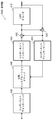
- FIG. 1 is a block diagram illustrating an example configuration of a transmitter that uses a rotational constellation with general quasi-cyclic low density parity check code and time-frequency slicing.
- FIG. 2 is a diagram illustrating an example of a parity check matrix of a pseudo cyclic low density parity check code.
- FIG. 3 is a block diagram illustrating a configuration example of the bit interleaver of FIG.
- FIG. 4 is a diagram illustrating an example of section permutation by the section interleaver of FIG.
- FIG. 5A is a diagram illustrating an example of a writing process of a codeword to a multi-bit interleaver matrix.
- FIG. 5B is a diagram illustrating an example of a process of reading a plurality of bits of a code word from an interleaver matrix.
- FIG. 6 is a block diagram showing another configuration example of the bit interleaver of FIG.
- FIG. 7 is a diagram illustrating an example of time-frequency slicing.
- FIG. 8 is a diagram illustrating an example of slicing of one code word.
- FIG. 9 is a block diagram showing a part of the configuration of the transmitter of FIG.
- FIG. 10 is a diagram illustrating a bit arrangement in the bit interleaver in the previous stage of the PAM mapper in FIG.
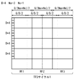
- FIG. 11A is a diagram showing a component arrangement at the time of writing in the component interleaver of FIG.
- FIG. 11A is a diagram showing a component arrangement at the time of writing in the component interleaver of FIG.
- FIG. 11B is a diagram showing a component arrangement after cyclic shift in the component interleaver of FIG. 9.
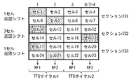
- FIG. 12 is a diagram showing a cell arrangement at the time of writing by the cell interleaver of FIG.
- FIG. 13 is a diagram illustrating a state of time-frequency slicing of 2 TFS cycles in a 2-frequency channel with respect to the cell arrangement of FIG.
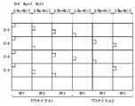
- FIG. 14A is a diagram showing a cell arrangement at the time of writing in a component interleaver in which two components corresponding to FIG. 11A are replaced with one cell.
- FIG. 14B is a diagram showing a cell arrangement after cyclic shift in a component interleaver in which two components corresponding to FIG. 11B are replaced with one cell.
- FIG. 12 is a diagram showing a cell arrangement at the time of writing by the cell interleaver of FIG.
- FIG. 13 is a diagram illustrating a state of time-frequency slicing of 2 TFS cycles in a 2-frequency channel with respect
- FIG. 15 is a diagram illustrating another example of the cell arrangement after the cyclic shift with respect to FIG. 14A.
- FIG. 16 is a diagram showing a state of time-frequency slicing of 2 TFS cycles in a 2-frequency channel for the cell arrangement of FIG.
- FIG. 17 is a block diagram illustrating a configuration example of a transmitter according to an embodiment of the present disclosure.
- FIG. 18A is a diagram illustrating an example of a cyclic shift based on a full shift pattern and a short shift pattern by the component interleaver of FIG.
- FIG. 18B is a diagram illustrating an example of a cyclic shift based on a full shift pattern and a short shift pattern by the component interleaver in FIG.
- FIG. 19A is a diagram for explaining an example of a cyclic shift by the component interleaver of FIG.
- FIG. 19B is a diagram for explaining an example of a cyclic shift by the component interleaver of FIG. 20A is a diagram for explaining another example of the cyclic shift by the component interleaver in FIG.
- FIG. 20B is a diagram for explaining another example of the cyclic shift by the component interleaver in FIG.
- FIG. 21 is a block diagram illustrating a configuration example of a receiver according to the embodiment of the present disclosure.
- FIG. 22 is a block diagram illustrating another configuration example of the receiver according to the embodiment of the present disclosure.
- FIG. 23 is a block diagram illustrating still another configuration example of the receiver according to the embodiment of the present disclosure.
- FIG. 24 is a block diagram illustrating still another configuration example of the receiver according to the embodiment of the present disclosure.
- FIG. 1 is a diagram of a transmitter that uses a rotating constellation with a general quasi-cyclic low-density parity check (QC LDPC) code and time-frequency slicing (TFS). It is a block diagram which shows the example of a structure. However, the configuration example of the transmitter in FIG. 1 is simplified to include only the configuration related to the present disclosure.
- QC LDPC quasi-cyclic low-density parity check
- TMS time-frequency slicing
- the transmitter 100 includes a low-density parity check (LDPC) encoder 110, a bit interleaver 120, a PAM (pulse amplitude modulation) mapper 130, a component deinterleaver 140, a constellation rotator 150, and a component interleaver 160.
- LDPC low-density parity check
- PAM pulse amplitude modulation
- the transmitter 100 receives a binary block having a predetermined length including information to be transmitted as an input.
- the LDPC encoder 110 encodes each information block using a low density parity check code (for example, a pseudo cyclic low density parity check code including a repeat accumulated pseudo cyclic low density parity check code).
- a low density parity check code for example, a pseudo cyclic low density parity check code including a repeat accumulated pseudo cyclic low density parity check code.
- the code word obtained by the encoding process (hereinafter referred to as “LDPC block” as appropriate) is supplied to the bit interleaver 120.
- the bit interleaver 120 performs bit interleaving for rearranging the plurality of bits according to a predetermined bit rearrangement rule for the LDPC block.
- the LDPC block subjected to bit interleaving is supplied to the PAM mapper 130.
- the PAM mapper 130 sequentially converts a predetermined number of bits into a real-valued PAM (real-valued pulse amplitude modulation) symbol (hereinafter, “real PAM (real pulse amplitude modulation) symbol”, or It is simply described as “PAM symbol” as appropriate.
- This predetermined number is denoted as “B”.
- each PAM symbol takes one value from a discrete set containing 2 B values. Note that how B bits are mapped to PAM symbols is well understood and is not directly related to this disclosure.
- An aspect related to this disclosure is that each LDPC block is converted into a block of multiple PAM symbols. The two PAM symbols later become complex QAM symbols (complex quadrature amplitude modulation) symbols, and the complex QAM symbols are sometimes called cells. Note that a plurality of cells may be arbitrarily rearranged by a cell interleaver.
- a plurality of PAM symbols obtained as a result of mapping are supplied to the component deinterleaver 140.
- the component deinterleaver 140 performs component deinterleaving that uses a PAM symbol as a component and rearranges a plurality of components according to a predetermined component rearrangement rule.
- a plurality of PAM symbols subjected to component deinterleaving are supplied to the constellation rotator 150.
- the constellation rotator 150 performs dedicated conversion on a plurality of supplied PAM symbols.
- Dedicated conversion processing by the constellation rotator 150 is performed by dividing a plurality of PAM symbols into, for example, groups of D PAM symbols supplied continuously, and in each group, D PAM symbols are set to D-dimensional values. It includes a process (rotation process) of multiplying a square vector of D rows and D columns by a dimension vector.
- D-dimensional vector having D PAM symbols as D-dimensional values is treated as indicating a unique point in the D-dimensional space. If each PAM symbol is made up of B bits, (2 B ) D combinations form a D-dimensional constellation. Thus, matrix multiplication is considered a rotation in D-dimensional space, and thus the term “rotated constellations” is used.
- D-dimensional constellation block a D-dimensional vector that is multiplied by a square orthogonal matrix
- D-dimensional constellation block A D-dimensional vector obtained as a result of multiplication of a square orthogonal matrix is appropriately described as “D-dimensional rotation vector” or “D-dimensional rotation constellation block”, and each D-dimensional value of the D-dimensional rotation constellation block is “rotated”. It will be described appropriately as “PAM symbol”.
- a plurality of rotated PAM symbols obtained as a result of the rotation process are supplied to the component interleaver 160.
- the component interleaver 160 performs component interleaving in which a plurality of components are rearranged according to a predetermined component rearrangement rule using the rotation PAM symbol as a component.
- the cell interleaver 170 performs cell interleaving for rearranging a plurality of cells according to a predetermined cell rearrangement rule.
- Patent Document 3 disclose serially connected component deinterleavers, constellation rotators, component interleavers, and cell interleavers.
- a plurality of cells subjected to cell interleaving are supplied to the scheduler 180.
- the scheduler 180 performs processing such as time-frequency slicing (TFS) for arranging a plurality of cells in an effective RF (radio frequency) channel according to a predetermined arrangement rule, and the plurality of cells are modulated by a modulator 190. -1 to 190-n.
- TFS time-frequency slicing
- a time interleaver (not shown) and a frequency interleaver may be arranged between the cell interleaver 170 and the modulators 190-1 to 190-n to further spread in time and frequency. .
- the modulators 190-1 to 190-n perform modulation processing on the complex cells supplied from the scheduler 180 and transmit the modulated cells via the transmission antennas 200-1 to 200-n.
- the modulation scheme may be orthogonal frequency-division multiplexing (OFDM).
- LDPC low-density parity check
- the LDPC code is a linear error correction code that is completely defined by a parity check matrix (PCM), as is well known in the digital communication field.
- PCM parity check matrix
- the PCM is a binary sparse matrix that represents a connection between a codeword bit (also referred to as “variable node”) and a parity check (also referred to as “check node”).
- the PCM columns and rows correspond to variable nodes and check nodes, respectively.
- the connection between the variable node and the check node is represented by an entry of “1” in the PCM (matrix element value “1”).
- LDPC code is a quasi-cyclic low-density parity check (QC LDPC) code, and the QC LDPC code has a structure particularly suitable for hardware implementation.
- QC LDPC codes are used in most standards today.
- the PCM of the QC LDPC code has a special structure having a plurality of circulant matrices (also referred to as “circulants”).
- a cyclic matrix is a square matrix in which each row is obtained by cyclically shifting a matrix element by one with respect to the previous row, and may have one or more cyclically shifted diagonal lines (cyclically shifted diagonal). It is.
- each cyclic matrix is Q rows and Q columns, and Q is called a cyclic factor of the QC LDPC code.
- Q is called a cyclic factor of the QC LDPC code.
- matrix elements having a value “1” are represented by black squares
- matrix elements having a value “0” are represented by white squares.
- This Q-bit block is referred to as a “cyclic block” or a “pseudo cyclic block” and is referred to as “QB” as appropriate throughout this document.
- the PCM QC LDPC code shown in FIG. 2 is a special type of QC known as a repeat-accumulate quasi-cyclic low-density parity check (RA QC LDPC) code. It belongs to the LDPC code.
- the RA QC LDPC code is well known for its ease of encoding and has been adopted in many standards such as second generation DVB standards such as DVB-S2, DVB-T2, and DVB-C2.
- the right side (parity part) corresponding to the parity bit of PCM has a structure in which the arrangement positions of matrix elements having a value “1” are stepped.
- the left side of the PCM is a portion (information portion) corresponding to the information bit.
- bit interleaver 120 in FIG. 1 will be described with reference to FIG. Note that, as a document disclosing a parallel bit interleaver similar to the parallel bit interleaver included in the bit interleaver in FIG. 3, for example (see Patent Document 5).
- the bit interleaver 120 includes a parallel bit interleaver 121 particularly adapted to the structure of the QC LDPC code.
- the number of cyclic blocks per codeword is expressed as “N”.
- N cyclic blocks of the 1QC LDPC codeword are divided into sections including the same number of cyclic blocks.
- N is a multiple of M described later
- Q is a multiple of 2.
- Q 360.
- One square in FIGS. 5A and 5B corresponds to one bit of the code word.
- the section interleaver 121-1 performs processing equivalent to the following processing.
- section permutation described in FIG. 4 and FIGS. 5A and 5B can be applied to the section permutation by the section interleavers 121-2 and 121-3.
- the parallel bit interleaver in FIG. 3 includes a section interleaver in each of a plurality of sections. Instead, the parallel bit interleaver has a smaller number of section interleavers than the number of sections, and uses the provided section interleaver in time division to perform section permutation separately for multiple sections. You may do it.
- the arrangement order of the plurality of cyclic blocks in the QC LDPC codeword may be changed according to a predetermined permutation.
- the permutation is called cyclic block permutation (QB permutation).
- the arrangement order of the Q bits in the cyclic block may be changed using a predetermined permutation rule.
- the permutation is called cyclic intra-block permutation (Intra QB permutation), and a normal cyclic shift is used for Intra QB permutation.
- the shift values are usually different from one another in each cyclic block, but the same shift value may be used in at least some cyclic blocks.
- FIG. 6 is a block diagram showing a configuration example of a bit interleaver having functions of QB permutation and Intra QB permutation.
- the bit interleaver 120A includes a section interleaver 121 that executes section permutation, a QB interleaver 123 that executes QB permutation, and an Intra QB interleaver 125 that executes Intra QB permutation. -1 to 125-12.
- bit interleaver in FIG. 6 includes an Intra QB interleaver in each of a plurality of cyclic blocks. Instead, the bit interleaver has a smaller number of Intra QB interleavers than the number of sections. Intra QB permutation is performed separately for multiple cyclic blocks using the provided Intra QB interleaver in time division. May be executed.
- QB permutation and Intra QB permutation are important for optimizing communication performance, but are not directly related to the present disclosure.
- QB permutation and Intra QB permutation can be considered as part of the definition of QC LDPC codes.
- QB permutation is equivalent to permutation of a row of cyclic blocks in the original PCM (in the case of FIG. 2, one row of cyclic blocks corresponds to 8 matrix elements).
- the cyclic shift in Intra QB permutation is equivalent to further cyclically shifting the original cyclically shifted diagonal line in PCM by (qmodQ).
- q is a shift value for circulating Q bits by Intra QB permutation. The same shift value is applied to all diagonals of all cyclic blocks in the same column of PCM.
- Rotational constellation is an effective tool for improving the robustness of communication systems in transmission lines with deep fading and disappearance.
- the basic idea of the rotation constellation is to create signal space diversity by transmitting a single piece of binary information simultaneously using a plurality of components.
- the constellation rotator 150 performs the following processing.
- D is preferably a power of 2, for example, 2 or 4.
- the D-row D-column square orthogonal matrix used here is a matrix in which the values of each dimension of the D-dimensional vector are distributed into at least two dimensions of the D-dimensional rotation vector.
- An example of such an orthogonal matrix is a matrix in which the absolute values of all elements on the main diagonal are equal to the real value a, and the absolute values of all elements not on the main diagonal are equal to the non-zero real value b. Can do.
- i 1 to D.
- D rotation PAM symbols (rotation components) of a D-dimensional rotation constellation block are distributed as evenly as possible in the interleaving period, (2)
- D rotation PAM symbols of the D-dimensional rotation constellation block are mapped to all possible RF channels. It is necessary to guarantee that. When both conditions (1) and (2) cannot be satisfied, it is desirable to guarantee the latter condition (2) at the expense of the former condition (1).
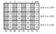
- the component interleaver 160 performs component interleaving equivalent to the following processing in each of the sections having a one-to-one correspondence with the section of the bit interleaver 120.
- the component interleaver 160 writes D ⁇ Q rotation components in the D-row / Q-column interleaver matrix in the column direction in the order of output of the rotation PAM symbols of the constellation rotator 150, using the rotation PAM symbols as rotation components. Note that the D rotation components in one column of the interleaver matrix are included in the same one-dimensional rotation constellation block.
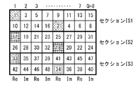
- the component interleaver 160 cyclically shifts each row of the interleaver matrix.
- the shift value of the first row of the interleaver matrix is set to 0, and the cyclic shift whose shift value is increased by Q / D PAM symbols from the cyclic shift applied to the previous row is applied to each row of the interleaver matrix. .
- the component interleaver 160 reads the rotation components in the row direction from the interleaver matrix after the cyclic shift, and outputs the rotation components in the read order.
- the two rotation components output in succession are mapped to one cell having a real component and an imaginary component, respectively, and are sequentially supplied to the cell interleaver 170.
- the cell interleaver 170 writes (N / M) ⁇ D ⁇ (Q / 2) cells in the row direction into an (N / M) ⁇ D row Q / 2 column interleaver matrix in the input order. Cell interleaving equivalent to reading cells from the matrix in the column direction and outputting the cells in the read order is performed.
- the component deinterleaver 140 performs component deinterleaving equivalent to the following processing in each of the sections having a one-to-one correspondence with the section of the bit interleaver 120.
- the component deinterleaver 140 writes the PAM symbols in the order of output of the PAM symbols of the PAM mapper 130 in the column direction into the D-row Q-column interleaver matrix as components.
- the component deinterleaver 140 cyclically shifts each row of the interleaver matrix.
- the shift value of the first row of the interleaver matrix is set to 0, and the cyclic shift in which the shift value is reduced by -Q / D PAM symbols from the cyclic shift applied to the previous row is applied to each row of the interleaver matrix.
- the cyclic shift by the component deinterleaver 140 and the cyclic shift by the component interleaver 160 are exactly opposite.
- the component deinterleaver 140 reads the components in the column direction from the interleaver matrix after the cyclic shift, and outputs the components in the read order.
- component deinterleaver 140 or the component interleaver 160 may include an interleaver for each section so as to perform component deinterleaving or component interleaving.
- component deinterleaver 140 or the component interleaver 160 includes a smaller number of interleavers than the number of sections, and the component deinterleaver or the component interleaver 160 is separately provided for a plurality of sections by using the provided interleaver in time division. Component interleaving may be performed.
- TFS is an effect for improving the robustness of a communication system in a transmission path with deep fading and loss that effectively utilizes diversity (hereinafter, referred to as “channel diversity” as appropriate) using a plurality of RF channels. Tool.
- Frequency diversity is a major type of channel diversity. Frequency diversity is due to the fact that fading in a radio channel tends to be frequency selective, and thus the fading correlation between any two RF channels is relatively low. Furthermore, so-called spatial diversity is exploited when transmitters using different RF channels are located at different geographical locations. Thus, channel diversity is due to both frequency diversity and spatial diversity.
- TFS scheduling (a (time-frequency slicing schedule). Based on the TFS scheduling, the receiver can extract desired data from each RF channel in an appropriate slice period while switching the RF channel between a plurality of RF channels. TFS scheduling (time-frequency allocation) is usually notified to the receiver using dedicated signaling information.
- Fig. 7 shows an example of TFS scheduling.
- the number of RF channels is 3, and the number of TFS cycles is 3.
- nine slices are sequentially arranged in the RF channel while repeating the order of the RF channels RF1, RF2, and RF3. Note that it is required to insert a guard period between two consecutive slices so that the receiver tuner can receive slices while switching between RF channels.
- N RF the number of RF channels in TFS multiplexing
- Optimal diversity is achieved when all slices are the same length and each LDPC block has the same number of cells in all slices.
- FIG. 8 shows an example of slicing of the FEC block.
- the number of RF channels is 3 and the number of TFS cycles is 3, which corresponds to an example of TFS scheduling in FIG.
- the slicing process is simple.
- the scheduler 180 includes a plurality of cells output from the cell interleaver 170 such that consecutively output cells are included in the same slice.
- a component deinterleaver 140 is disposed between the PAM mapper 130 and the constellation rotator 150. However, since the component deinterleaver 140 is not particularly related to the problem when the above-described unit is applied to TFS, it is omitted in FIG. 9 for simplification of description.
- FIG. 10 shows the bit arrangement in the bit interleaver in the previous stage of the PAM mapper 130.
- one square in FIG. 10 corresponds to one bit, and the index b in the square indicates the input order of bits.
- each column of each section IS1 to IS3 is a bit group that forms the basis of one two-dimensional rotation constellation block.
- PAM3, PAM4 the two-dimensional vector
- the component interleaver 160 performs the following processing in each of the sections having a one-to-one correspondence with the sections IS1 to IS3 of the bit interleaver 120.
- the arrangement of the rotating components in the component interleaver 160 is as shown in FIG. 11A. Note that one square in FIG. 11A and FIG. 11B described later corresponds to one rotation component, and the numbers in the square indicate the input order of the rotation components.
- the hatched rotation component is later transmitted in the real component of the cell, and the unhatched component is later transmitted in the imaginary component of the cell.
- the two rotation components output in succession are mapped to one cell having a real component and an imaginary component, respectively, and are sequentially supplied to the cell interleaver 170.
- Output Note that the cell arrangement at the time of writing in the cell interleaver 170 is as shown in FIG. Note that one square in FIG. 12 corresponds to one cell, and the numbers in the square indicate the input order of the cells.
- the same hatch is put in two cells in which two rotation components having the same hatching in FIG. 11B are respectively real components. That is, for example, the same hatch as the rotation components 1 and 2 is put in the cells 1 and 7 having the two rotation components 1 and 2 of the two-dimensional rotation constellation block as real components.
- the real component of cell 1 and the real component of cell 7 corresponding to two rotating PAM symbols (rotating components) of one two-dimensional rotating constellation block are transmitted on the same RF channel RF1. If the RF channel RF1 is affected by deep fading, the two rotation PAM symbols of the two-dimensional rotation constellation block are lost, that is, the entire two-dimensional rotation constellation block is lost.
- the D rotation PAM symbols of the D-dimensional rotation constellation block are mapped to the same RF channel, and the entire D-dimensional rotation constellation block May be lost.
- the inventors examined how the rotating PAM symbols of the D-dimensional rotating constellation block can be distributed on as many RF channels as possible.
- the inventors replaced the components in two consecutive columns in the same row in FIGS. 11A and 11B with one cell having a real component and an imaginary component.
- the cell arrangement at the time of writing in the component interleaver corresponding to FIG. 11A is as shown in FIG. 14A
- the cell arrangement after the cyclic shift in the component interleaver corresponding to FIG. 11B is as shown in FIG.
- the cyclic shift value in the second row of each of the sections IS1 to IS3 is selected from the cyclic shift value 1 cell and 3 cells excluding 1 cell.
- the cyclic shift value is 1 cell in section IS1, 3 cells in section IS2, and 1 cell in section IS3.
- the result of TFS in this case is as shown in FIG. 16, and the two rotation components of the two-dimensional rotation constellation block are distributed on different RF channels.
- the real component of cell 1 and the real component of cell 5 corresponding to the two rotating components of one two-dimensional rotating constellation block are transmitted on RF channel RF1 and RF channel RF2, respectively.
- the two-dimensional rotating constellation block can be fully decoded by the other RF channels.
- the inventors have found that the D rotational components of the D-dimensional rotational constellation block can be arranged in as many RF channels as possible by appropriately selecting the cyclic shift value.
- the cyclic shift value can take a value between 0 and Q-1.
- the component interleaver 160 performs a cyclic shift using the cyclic shift value selected for each row so that the D rotation PAM symbols of the D-dimensional rotation block are distributed as evenly as possible to the FEC block. is there.
- the cyclic shift value is the cell granularity, ie a multiple of 2.
- FIG. 17 is a block diagram illustrating a configuration example of the transmitter according to the embodiment of the present disclosure.
- FIG. 17 has a configuration in which the component deinterleaver 140 of the conventional transmitter 100 of FIG. 1 is replaced with a component deinterleaver 140A, and the component interleaver 160 and the cell interleaver 170 are replaced with a component interleaver 160A. is doing.
- the same reference numerals are given to components that perform substantially the same functions or operations as the components of the transmitter 100 in FIG. 1, and the description thereof can be applied here. Omitted.
- the number of cyclic blocks N of one LDPC block is a multiple of the number of cyclic blocks M included in one section
- D is a power of 2 (for example, 2, 4)
- M B ⁇ It is assumed that it is D.
- the component interleaver 160A rotates the rotated PAM symbols in the input order of the rotated PAM symbols from the constellation rotator 150 in each section having a one-to-one correspondence with the (N / M) sections of the bit interleaver 120.
- D ⁇ Q rotation components are written in a column direction in an interleaver matrix of D rows and Q columns.
- the component interleaver 160A sets two adjacent real value rotation components (rotation PAM symbols) in the same row of the D-row Q-column interleaver matrix as a real component and an imaginary component, respectively.
- An interleaver matrix having one cell and a real-valued rotation component as an element, and an D-row (Q / 2) column interleaver matrix having a complex value component (cell) as an element hereinafter referred to as “complex interleaver”).
- Matrix matrix having one cell and a real-valued rotation component as an element
- the component interleaver 160A arranges N / M D rows (Q / 2) columns of complex interleaver matrices in the column direction (next to the last row of a certain complex interleaver matrix, another complex interleaver matrix). Arrange so that the first row of the matrix of In this way, N / M D-row (Q / 2) column complex interleaver matrices are combined to form a (N / M) ⁇ D-row (Q / 2) column complex interleaver matrix (hereinafter, It is described as “combined complex interleaver matrix”).
- the component interleaver 160A performs a cyclic shift on each row of the combined complex interleaver matrix.
- the cyclic shift performed by the component interleaver 160A will be described in detail later.
- the component interleaver 160A reads cells in the column direction from the combined complex interleaver matrix after the cyclic shift, and outputs them in the order of reading.
- the scheduler 180 divides output from the component interleaver 160A to (N / M) ⁇ D ⁇ (Q / 2) number of cells N RF ⁇ N C slices. Then, the scheduler 180, N RF pieces of RF channels RF1, RF2, RF3, while repeating the order of ..., will be placed RF channels N RF ⁇ N C slices in order.
- N C the number of TFS cycles N C is the number of changes between a set of N RF RF channels when one codeword is transmitted.
- the component deinterleaver 140A performs the following processing in each of the sections having a one-to-one correspondence with the (N / M) sections of the bit interleaver 120.
- the component deinterleaver 140A writes P ⁇ M components in the D-row / Q-column interleaver matrix in the column direction in the order of input of the PAM symbols from the PAM mapper 130, using the PAM symbols as components.
- the component deinterleaver 140A has, for each row, the shift value in units of cells that the component interleaver 160A uses for the cyclic shift for the row ( -1)
- a cyclic shift is performed in which a value obtained by multiplying ⁇ 2 is a shift value in PAM symbol units.
- a real value D row Q column interleaver matrix is defined as a complex value. It is equivalent to the next cyclic shift when considered as an interleaver matrix of D rows and Q / 2 columns.
- the component deinterleaver 140A is (-1) for each row with respect to the shift value that the component interleaver 160A uses for the cyclic shift for that row.
- a cyclic shift is performed in which a value obtained by multiplying is shifted by a cell unit.
- the component deinterleaver 140A reads the components in the column direction from the interleaver matrix of D rows and Q columns after the cyclic shift, and outputs them in the order of reading.
- the cyclic shift performed by the component interleaver 160A in the combined complex interleaver matrix will be described.
- the shift value of the cyclic shift is referred to using a complex QAM symbol (complex value cell) instead of a real-valued PAM symbol.
- the function floor (x) is a function that returns a maximum integer equal to or less than x.
- the set of all possible cyclic shift values is ⁇ 0, W, 2 ⁇ W,..., (Max ⁇ D, (N RF ⁇ N C ) ⁇ ⁇ 1) ⁇ W ⁇ .
- the column width in the combined complex interleaver matrix of all slices other than the last slice is floor ⁇ Q / (N RF ⁇ N C ) / 2 ⁇ cells.
- the column width in the combined complex interleaver matrix of the last slice is [Q / 2 ⁇ (N RF ⁇ N C ⁇ 2) ⁇ floor ⁇ Q / (N RF ⁇ N C ) / 2 ⁇ ] / 2 cells. is there. Note that this description, N RF ⁇ N C is available even if the divisor of Q / 2.
- cyclic shift value actually used by the component interleaver 160A a set of all possible cyclic shift values ⁇ 0, W, 2 ⁇ W,..., (Max ⁇ D, (N RF ⁇ N C ) ⁇ -1) ⁇ W ⁇ how to choose is described.
- the component interleaver 160A performs a cyclic shift on each of the D rows using a multiplication value (unit cell) obtained by multiplying the value of the coefficient of W applied to the row and W as a cyclic shift value.
- the D-dimensional rotation constellation block is transmitted using two RF channels.
- N RF ⁇ D if the number of integers with different values obtained by k mod N RF is D, the D-dimensional rotation constellation block is transmitted using D RF channels.
- N RF ⁇ D and N RF ⁇ N C ⁇ D when the number of different integer values obtained by k mod N RF is N RF , the number of D-dimensional rotation constellation blocks is N RF . It is transmitted using the RF channel.
- the greater the number of different values obtained by K mod N RF the more RF channels will transmit a D-dimensional rotation constellation block.
- a D-dimensional rotation constellation When N RF ⁇ D or N RF ⁇ D and N RF ⁇ N C ⁇ D, and the number of different integer values obtained by k mod D is D, a D-dimensional rotation constellation The block will be transmitted using D RF channels. The greater the number of different values obtained by k mod D, the more RF channels will be transmitted in the D-dimensional rotation constellation block.
- the D k values of the section use set selected so that the number of the different integer values is maximized, and the number of the same integer values obtained by k mod N RF and k mod D are as equal as possible. You may choose to be.
- the D rotational components of the D-dimensional rotational constellation block are distributed as evenly as possible to the N RF RF channels.
- L, M, and N are different integers of 1 or more.
- the following W coefficient k selection method may be added.
- the set ⁇ 0, 1, 2,..., (Max ⁇ D, (N RF ⁇ N C ) ⁇ ⁇ 1) ⁇ is selected at least once as the coefficient k of W To be.
- the maximum effect can be obtained by separating the D components of the D-dimensional rotation constellation block as evenly as possible by frequency and time.
- the short shift pattern is obtained by changing the full shift pattern so that the dispersion of the D rotation components of the D-dimensional rotation constellation block in time becomes small.
- the cyclic shift value for the first row of each section is 0, and the cyclic shift value of the other rows is 1 to max ⁇ D, (N RF ⁇ N C ) ⁇ . Values of -1 are arranged in order.
- the component interleaver 160A repeatedly uses the value k in the pattern excluding ⁇ 0 ⁇ of the full shift pattern in order from the first in each row except the first row of each section of the entire combined complex interleaver matrix. Cyclic shift of shift value k ⁇ W cell is performed. That is, when viewed as a matrix obtained by removing the first row of each section from the entire combined complex interleaver matrix, ⁇ 0 ⁇ from the full shift pattern is sequentially applied to each row of the removed matrix from the first row. It is used repeatedly from the first value in the excluded pattern.
- the component interleaver 160A performs a cyclic shift based on 0, 1, 2, 3 from the first row of the four rows of the first section. Subsequently, a cyclic shift based on 0, 1, 2, and 3 is performed on the four rows of the second section from the first row. Thereafter, the same process is repeated.
- N RF 3
- N C 2
- a full shift pattern it is as follows.
- the component interleaver 160A performs a cyclic shift based on 0, 1, 2, 3 from the first row of the four rows of the first section. Subsequently, a cyclic shift based on 0, 4, 5, and 1 is performed on the four rows in the second section from the first row. Subsequently, cyclic shift using 0, 2, 3, 4 is performed on the 4th row of the third section from the first row. Subsequently, a cyclic shift using 0, 5, 1, 2 is performed on the four rows of the fourth section from the first row. Subsequently, cyclic shift using 0, 3, 4, and 5 from the first row is performed on the four rows of the fifth section. Thereafter, the same process is repeated.
- the component interleaver 160A repeatedly assigns each row of the combined complex interleaver matrix from the top row using the short shift pattern repeatedly.
- W floor (Q / max ⁇ D, (N RF ⁇ N C ) ⁇ / 2)
- the average value of the shift values in the full shift pattern and the short shift pattern are both 4 and the same.
- the dispersion of shift values in the full shift pattern and the short shift pattern is 6.667 and 2, respectively, and the dispersion in the short shift pattern is smaller than the dispersion in the full shift pattern.
- FIGS. 19A and 20A show the combined complex interleaver matrix before the cyclic shift
- FIGS. 19B and 20B show the combined complex interleaver matrix after the cyclic shift.
- FIGS. 19A and 19B and FIGS. 20A and 20B only the cells in the first column before applying the cyclic shift of sections IS1 to IS4 are indicated by squares.
- Q / 2 is a multiple of D.
- the component interleaver 160A selects 0, 1, 2, and 3 for each of the four rows of each section as the k value of the cyclic shift value k ⁇ W, and selects the selected k.
- the cyclic shift is performed by the cyclic shift value k ⁇ W based on the value of. As a result, those shown in FIGS. 19A to 19B are obtained.
- the component interleaver 160A selects 0, 1, 2, 3 for each of the four rows of the first section as the value of k of the cyclic shift value k ⁇ W, Select 0, 4, 5, 1 for each of the 4th row of the second section, and select 0, 2, 3, 4 for each of the 4th row of the third section. Choose 0, 5, 1, 2 for each of the four lines in the section.
- the component interleaver 160A performs a cyclic shift by the cyclic shift value k ⁇ W based on the selected value of k. As a result, the configuration shown in FIGS. 20A to 20B is obtained.
- the scheduler 180 divides the output is a cell component interleaver 160A, the N RF ⁇ N C slices consisting of cells each are continuously outputted. Then, the scheduler 180 uses repeatedly the N RF number of RF channels in sequence, it will be assigned to RF channel N RF ⁇ N C slices in order.
- All the slices except the last slice are composed of cells of floor ⁇ Q / (N RF ⁇ N C ) / 2 ⁇ columns of the combined complex interleaver matrix.
- the last slice is composed of [Q / 2 ⁇ (N RF ⁇ N C ⁇ 2) ⁇ floor ⁇ Q / (N RF ⁇ N C ) / 2 ⁇ ] / 2 columns of cells. Note that this description is available both when Q / 2 is not the case and a multiple of a multiple of N RF ⁇ N C.
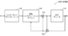
- FIG. 21 is a block diagram illustrating a configuration example of a receiver according to the embodiment of the present disclosure.
- the receiver 500 reflects the function of the transmitter 100A of FIG. 17, and includes a receiving antenna 510, an RF front end 520, a component deinterleaver 530, a rotation constellation demapper 540, a component interleaver 550, a bit deinterleaver 560, And an LDPC decoder 570.
- the RF front end 520 extracts (N / M) ⁇ D ⁇ (Q / 2) complex symbols (cells) from the N RF RF channels in accordance with the TFS scheduling information and outputs them.
- the component deinterleaver 530 is equivalent to the following process for returning the arrangement of (N / M) ⁇ D ⁇ (Q / 2) cells before the arrangement by the component interleaver 160A of the transmitter 100A.
- the processing based on the component deinterleaver 530 uses a rearrangement rule opposite to the rearrangement rule by the component interleaver 160A.
- the component deinterleaver 530 combines (N / M) ⁇ D ⁇ (Q / 2) cells of (N / M) ⁇ D rows (Q / 2) columns in the input order from the RF front end 520. Write to the interleaver matrix in the column direction.
- the component deinterleaver 530 performs a cyclic shift exactly opposite to the cyclic shift performed by the component interleaver 160A of the transmitter 100A for each row of the combined complex interleaver matrix (used by the component interleaver 160A).
- the cyclic shift value is A
- the cyclic shift value used by the component deinterleaver 530 is -A).
- the component deinterleaver 530 converts the combined complex interleaver matrix of (N / M) ⁇ D rows (Q / 2) columns after the cyclic shift into (N / M) D rows (Q / 2) columns.
- Divide into complex interleaver matrices That is, (N / M) ⁇ D ⁇ (Q / 2) cells, each having a one-to-one correspondence with the section of the bit interleaver 120 of the transmitter 100A, are (N / M) cells.
- the Lever matrix is converted to a real interleaver matrix with D rows and Q columns.
- the component deinterleaver 530 reads the rotation components from the real interleaver matrix of D rows and Q columns in the column direction, and outputs them in the read order.
- the rotation constellation demapper 540 groups consecutive D components input from the component deinterleaver 530, sequentially demaps them, extracts (soft) bits, and outputs them to the component interleaver 550. .
- the rotational constellation demapper 540 performs constellation derotator and QAM demapping in one block.
- the component interleaver 550 is equivalent to the following process for returning the sequence of (N / M) ⁇ D ⁇ Q B (soft) bits before the rearrangement by the component deinterleaver 140A of the transmitter 100A.
- Process the processing based on the component interleaver 550 uses a rearrangement rule opposite to the rearrangement rule by the component deinterleaver 140A.
- the B (soft) bit corresponds to a component of the component deinterleaver 140A, and in the following, a group of B (soft) bits is described as “(soft) bit group”.
- the component interleaver 550 sets Q ⁇ D (soft) bit groups to D in the order of input from the rotation constellation demapper 540 in each of the sections having a one-to-one correspondence with the section of the component deinterleaver 530. Write to the interleaver matrix of row Q column in the column direction. Then, the component interleaver 550 performs a cyclic shift exactly opposite to the cyclic shift performed by the component deinterleaver 140A of the transmitter 100A (if the cyclic shift value used by the component deinterleaver 140A is A, the component interleaver 550). The cyclic shift value used by 550 is -A). Then, the component interleaver 550 reads (soft) bit groups in the column direction from the interleaver matrix of D rows and Q columns after the cyclic shift, and outputs them in the order of reading.
- the bit deinterleaver 560 is arranged in the column direction into the bit interleaver matrix of M rows and Q columns in the order of input from the component interleaver 550. Write, read (soft) bits from the interleaver matrix in the row direction, and output them in the read order.
- the transmitter 100A when a function for executing the above-described QB permutation and / or intra QB permutation is added, intra deblintering is performed on the bit deinterleaver 560 after deinterleaving for the above (soft) bits. What is necessary is just to add the function which performs the interleaving of the rule contrary to QB permutation and / or QB permutation.
- the LDPC decoder 570 decodes the deinterleaved N ⁇ Q (soft) bits. Note that the decoding process by the LDPC decoder 570 is based on the encoding process performed by the LDPC encoder 110 of the transmitter 100A.
- the cyclic shift by the component interleaver 550 can be incorporated into a cyclic shift related to intra QB permutation executed by the bit deinterleaver 560. That is, it can be incorporated into the definition of the LDPC code. Therefore, the component interleaver 550 need not be implemented in hardware.
- receiver 500A using iterative decoding will be described with reference to FIG.
- processing blocks that perform substantially the same processing as in FIG.
- a bit interleaver and a bit deinterleaver corresponding to the bit interleaver 120 are not included because they are not necessary for hardware.
- the receiver 500A includes a component deinterleaver 530, a rotation constellation demapper 540, a component interleaver 550, an adder 610, an LDPC decoder 570, a subtractor 620, and a component deinterleaver 630. Since the basic principle of iterative decoding is well known in the field of digital communication, only a brief description will be given here.
- the rotational constellation demapper 540 does not receive a priori information (a-priori information), performs demapping of the cell (without the help of prior information), and obtains the software obtained by the demapping.
- Output bits (a measure of the posterior probability of bits, typically expressed as a log-likelihood ratio).
- the component interleaver 550 performs interleaving on the output of the rotational constellation demapper 540.
- Adder 610 adds 0 to the output of component interleaver 550, and LDPC decoder 570 performs LDPC decoding on the output of adder 610.
- the subtracter 620 calculates external information (extrinsic information) by subtracting the output of the LDPC decoder 570 from the output of the adder 610, and uses the external information as a priori information as the component deinterleaver 630. To supply.
- the component deinterleaver 630 deinterleaves the output of the subtractor 620 and outputs the deinterleaved prior information to the rotation constellation demapper 540.
- Rotational constellation demapper 540 performs demapping using cells and prior information, and outputs soft bits obtained by demapping.
- the component interleaver 550 performs interleaving on the output of the rotational constellation demapper 540.
- Adder 610 adds the output of component interleaver 550 and the output of subtractor 620, and LDPC decoder 570 performs LDPC decoding on the output of adder 610.
- the component deinterleaver 630 outputs Q ⁇ D pieces of external information in a D-row / Q-column interleaver matrix in the input order of the subtractor 620 in each of the sections having a one-to-one correspondence with the section of the component interleaver 550. Write in the column direction. Then, the component deinterleaver 630 performs a cyclic shift exactly opposite to the cyclic shift performed by the component interleaver 550 (when the cyclic shift value used by the component interleaver 550 is A, the cyclic used by the component deinterleaver 630). The shift value is -A). Then, the component deinterleaver 630 reads external information in the column direction from the interleaver matrix of D rows and Q columns after the cyclic shift, and outputs the information in the order of reading.
- the component interleaver 550 and the component deinterleaver 630 are part of an iterative decoding loop. This makes it much easier to implement an iterative decoding decoder if they are implemented using cyclic shifts.
- the cyclic shift performed by these can be incorporated into the definition of the LDPC code used by the LDPC decoder 570 together with the cyclic shift of the bit deinterleaver. Therefore, as shown in FIG. 23, the structure of the receiver 500B is made such that the component interleaver 550 and the component deinterleaver 630 are removed from between the rotating constellation demapper 540 and the adder 610 from the receiver 500A. be able to.
- the component deinterleaver 530 replaces the D row and Q column of each section having a real value as a component with the D row Q / 2 column having two consecutive components in the same row as one cell. Does the following: The component deinterleaver 530A reads Q / 2 cells for one row of the matrix of D rows and Q / 2 columns from each cell memory 710 in each section, performs cyclic shift, and writes back to the same location, that is, the same address after the cyclic shift. . There is no additional memory, and the cyclic shift is performed in units of rows instead of the entire FEC block, so the latency is very small.
- N is a multiple of M, but N is not necessarily a multiple of M. Not necessarily.
- N is not a multiple of M, do the following: The following description is applicable when N is a multiple of M.
- the following processing is performed on the sending side.
- N-rem (N, M) cyclic blocks are removed from N cyclic blocks. Then, N-rem (N, M) cyclic blocks are divided into floor (N / M) sections each including M cyclic blocks. However, the number of cyclic blocks to be excluded is 0 or more and M ⁇ 1 or less.
- the rem (N, M) cyclic blocks to be removed are selected from, for example, a parity part having low importance.
- bit interleaver 120, the component deinterleaver 140A, the constellation rotator 150, and the component interleaver 160A correspond to each of the floor (N / M) sections ⁇ investigation by the inventors and then the inventors.
- the process described in the section “Knowledge obtained” and ⁇ embodiment >> is performed.
- bit interleaver 120 may or may not rearrange the bits for rem (N, M) cyclic blocks.
- the component deinterleaver 140A may or may not rearrange the components.
- the constellation rotator 150 may or may not be rotated.
- the component interleaver 160A is located below the bottom row of the combined complex interleaver matrix of floor (N / M) ⁇ D rows Q / 2 columns created from floor (N / M) complex interleaver matrices. One or a plurality of rows are newly provided (the position of the newly provided row is not particularly limited).
- the component interleaver 160A may or may not perform the cyclic shift for the newly added portion.
- the following processing is performed on the receiving side.
- the component deinterleaver 530 writes the cells in the column direction in the combined complex interleaver matrix having the same size as the updated combined complex interleaver matrix on the transmission side in the input order from the RF front end 520. Then, the cyclic shift processing described in the ⁇ embodiment >> is performed in the portion corresponding to the floor (N / M) sections on the transmission side of the combined complex interleaver matrix. In a portion corresponding to rem (N, M) cyclic blocks, no cyclic shift is performed when no cyclic shift is performed on the transmission side, and a reverse cyclic shift is performed when a cyclic shift is performed. .
- the combined complex interleaver matrix after the cyclic shift is converted into a complex interleaver matrix of a section corresponding to each of the floor (N / M) sections on the transmission side and a matrix corresponding to rem (N, M) cyclic blocks. Divide. Then, the component deinterleaver 530 performs the reading process described in the ⁇ embodiment >> on the floor (N / M) sections, and the matrix corresponding to the rem (N, M) cyclic blocks. Cell read processing is performed so that the input is performed before the input of the component interleaver 160A on the transmission side.
- the rotation constellation demapper 540, the component interleaver 550, and the bit deinterleaver 560 correspond to each of the sections having a one-to-one correspondence with the floor (N / M) sections on the transmission side.
- the processing described in the embodiment >> is performed.
- the rotation constellation demapper 540 performs demapping considering rotation when rotation processing is performed on the transmission side. If not, demapping is performed without considering rotation.
- the component interleaver 550 does not perform rearrangement when component rearrangement is not performed on the transmission side, and performs reverse rearrangement when rearrangement is performed.
- the bit deinterleaver 560 does not perform the rearrangement when the bit rearrangement is not performed on the transmission side, and performs the reverse rearrangement when the rearrangement is performed.
- the component deinterleaver 630 performs the processing described in the “embodiment” for each of the sections having a one-to-one correspondence with the floor (N / M) sections on the transmission side.
- the component deinterleaver 630 does not perform the reordering in the part corresponding to the rem (N, M) cyclic blocks when the component interleaver 550 does not perform the component reordering. If so, reverse sorting is performed.
- the component deinterleaver 530 performs the processing described in the ⁇ embodiment >> for each of the sections having a one-to-one correspondence with the floor (N / M) sections on the transmission side.
- the component deinterleaver 530 does not perform reordering in the portion corresponding to the rem (N, M) cyclic blocks when the component is not reordered on the transmitting side. If so, reverse sorting is performed.
- Tables 3 and 4 show the number of sections and the number of cyclic blocks to be excluded for 16k LDPC codewords and 64k LDPC codewords normally used in DVB-T2 and DVB-NGH.
- the modulation multi-level numbers of all PAM symbols may be the same, or only a part of all PAM symbols may have the same modulation multi-level number (PAM symbols having different modulation multi-level numbers are created. May be.
- D all-dimensional PAM symbols of the D-dimensional vector are formed from B bits, for example, M is B ⁇ D as described above.
- the embodiment may relate to implementation using hardware and software.
- the above-described embodiments may be implemented or executed using a computing device (processor).
- the computing device or processor is, for example, a main processor / general processor (DSP), a digital signal processor (DSP), an ASIC (application specific integrated circuit), an FPGA (field programmable gate array), other programmable logic devices, etc. It may be.
- the above embodiments may be executed or realized by combining these devices.
- the embodiment may be realized by a mechanism of a software module executed by a processor or directly by hardware.
- a combination of software modules and hardware implementation is also possible.
- the software modules may be stored on various types of computer readable storage media, such as RAM, EPROM, EEPROM, flash memory, registers, hard disk, CD-ROM, DVD, etc.
- the first transmission method is A transmission method of transmitting one code block in a plurality of slices using N RF (integer greater than or equal to 2) frequency channels and N C (integer greater than or equal to 1) cycles,
- N RF integer greater than or equal to 2
- N C integer greater than or equal to 1
- a data block is encoded into the code block using a pseudo cyclic low density parity check code, and the encoded block includes N cyclic blocks, each of the N cyclic blocks includes Q bits, and the N blocks.
- the cyclic blocks are divided into floor (N / M) sections each consisting of M cyclic blocks and rem ⁇ N, M ⁇ cyclic blocks, For each said section, generate a D-dimensional constellation block consisting of D components, each of which is a real value, from the Q ⁇ M bits of the section; From each of the D-dimensional constellation blocks of each of the sections, a D-dimensional rotation constellation block consisting of D rotation components, each of which is a real value, using an orthogonal matrix of D rows and D columns, Mapping each rotational component of each of the D-dimensional rotational constellation blocks of each of the sections to one frequency channel of the N RF frequency channels; The transmission method, The mapping of each of the rotating components to the frequency channel is In each section, D ⁇ Q rotation components are written in a D-row / Q-column real interleaver matrix in the column direction, and each D-row / Q-column real interleaver matrix is rotated in two consecutive columns in the same row.
- D rotation components of the D-dimensional rotation constellation block can be transmitted by two or more frequency channels, and reception performance can be improved.
- the second transmission method is the first transmission method,
- D is 2
- the two rotation components of the two-dimensional rotation constellation block can be transmitted by different frequency channels, and the reception performance can be further improved.
- the third transmission method is the first transmission method,
- D is 4 and D is N RF or less
- L is an integer.
- the four rotation components of the four-dimensional rotation constellation block can be transmitted by different frequency channels, and the reception performance can be further improved.
- the first receiving method is: A reception method of receiving one code block divided into a plurality of slices using N RF (integer greater than or equal to 2) frequency channels and N C (integer greater than or equal to 1) cycles, Receiving a plurality of cells from the N RF (integer greater than or equal to 2) frequency channels according to time-frequency slicing schedule information; 2. Mapping real and imaginary components of the plurality of cells to D real-valued rotation components of a plurality of D-dimensional rotation constellation blocks based on the rules for mapping real-value rotation components to frequency channels of claim 1. And The plurality of D-dimensional rotation constellation blocks are decoded using a pseudo cyclic low density parity check code.
- D rotational components of the D-dimensional rotational constellation block can be received by two or more frequency channels, and the reception performance can be improved.
- the first transmitter is A transmitter for transmitting one code block in a plurality of slices using N RF (integer greater than or equal to 2) frequency channels and N C (integer greater than or equal to 1) cycles,
- N RF integer greater than or equal to 2
- N C integer greater than or equal to 1
- a data block is encoded into the code block using a pseudo cyclic low density parity check code, and the encoded block includes N cyclic blocks, each of the N cyclic blocks includes Q bits, and the N blocks.
- the cyclic blocks are divided into floor (N / M) sections each consisting of M cyclic blocks and rem ⁇ N, M ⁇ cyclic blocks, For each said section, generate a D-dimensional constellation block consisting of D components, each of which is a real value, from the Q ⁇ M bits of the section; From each of the D-dimensional constellation blocks of each of the sections, a D-dimensional rotation constellation block consisting of D rotation components, each of which is a real value, using an orthogonal matrix of D rows and D columns, Mapping each rotational component of each of the D-dimensional rotational constellation blocks of each of the sections to one frequency channel of the N RF frequency channels; A transmitter, The mapping of each of the rotating components to the frequency channel is In each section, D ⁇ Q rotation components are written in a D-row / Q-column real interleaver matrix in the column direction, and each D-row / Q-column real interleaver matrix is rotated in two consecutive columns in the same row.
- D rotation components of the D-dimensional rotation constellation block can be transmitted by two or more frequency channels, and reception performance can be improved.
- the first receiver A receiver for receiving one code block divided into a plurality of slices using N RF (integer greater than or equal to 2) frequency channels and N C (integer greater than or equal to 1) cycles, Receiving a plurality of cells from the N RF (integer greater than or equal to 2) frequency channels according to time-frequency slicing schedule information; 2. Mapping real and imaginary components of the plurality of cells to D real-valued rotation components of a plurality of D-dimensional rotation constellation blocks based on the rules for mapping real-value rotation components to frequency channels of claim 1. And The plurality of D-dimensional rotation constellation blocks are decoded using a pseudo cyclic low density parity check code.
- D rotational components of the D-dimensional rotational constellation block can be received by two or more frequency channels, and the reception performance can be improved.
- the present disclosure can be used for a communication system that uses a rotating constellation and a plurality of frequency channels together with a pseudo cyclic low density parity check code.
Abstract
本開示の一態様に係る送信方法は、各セクションの複数の回転コンポーネントを夫々が2つの回転コンポーネントを実数コンポーネント及び虚数コンポーネントとするセルに置き換えたインターリーバ行列の各行に対して、当該行に割り当てられた巡回シフト値k×floor(Q/max{D,(NRF×NC)}/2)セルを用いた巡回シフトを適用し、巡回シフトは結合複素インターリーバ行列の1つのセクション部分の少なくとも2つの行ではk mod NRFの値が異なる。
Description
本開示は、デジタル通信分野の技術に関し、特に、疑似巡回低密度パリティ検査(quasi-cyclic low-density parity check:QC LDPC)符号とともに回転コンステレーション及び複数の周波数チャネルを用いる通信システムの技術に関する。
近年、回転コンステレーションを用いるとともに複数の周波数チャネルを切り替えながらデータの送受信を行う通信システムがある(例えば、特許文献1参照)。
このような通信システムにおける送信機は、例えば、疑似巡回低密度パリティ検査(quasi-cyclic low-density parity check:QC LDPC)符号に基づく符号語を複数のコンポーネントに変換する。そして、D個のコンポーネントをグループとし、各グループにおいてD個のコンポーネントを各次元の値とするD次元ベクトル(D次元コンステレーションブロック)をD行D列の正方直交行列に乗算する(回転処理)。
そして、送信機は、チャネルダイバーシティを得るために、各回転が施されたD次元ベクトル(各D次元回転コンステレーションブロック)のD個の回転コンポーネントを複数の周波数チャネルに割り当てる。
本開示の一態様に係る送信方法は、NRF(2以上の整数)個の周波数チャネル及びNC(1以上の整数)個のサイクルを用いて1つの符号ブロックを複数のスライスに分けて送信する送信方法であって、疑似巡回低密度パリティ検査符号を用いてデータブロックを前記符号ブロックに符号化し、当該符号化ブロックはN個の巡回ブロックからなり、当該N個の巡回ブロックの夫々はQビットからなり、前記N個の巡回ブロックは、夫々がM個の巡回ブロックからなるfloor(N/M)個のセクションとrem{N,M}個の巡回ブロックとに分かられ、各前記セクションにおいて、当該セクションのQ×M個のビットから夫々が実数値であるD個のコンポーネントからなるD次元コンステレーションブロックを生成し、各前記セクションのD次元コンステレーションブロックの夫々から、D行D列の直交行列を用いて夫々が実数値であるD個の回転コンポーネントからなるD次元回転コンステレーションブロックを生成し、各前記セクションの夫々の各前記D次元回転コンステレーションブロックの各前記回転コンポーネントを前記NRF個の周波数チャネルの1つの周波数チャネルにマッピングする、送信方法であり、各前記回転コンポーネントの前記周波数チャネルへのマッピングは、各前記セクションにおいて、D×Q個の前記回転コンポーネントをD行Q列の実数インターリーバ行列に列方向に書き込み、各前記D行Q列の実数インターリーバ行列を同じ行の連続する2列の回転コンポーネントを1つの複素値であるセルに置き換えたD行(Q/2)列の複素インターリーバ行列に変換し、各前記セクションの前記D行(Q/2)列の複素インターリーバ行列を並べることによって、{floor(N/M)}×D行(Q/2)列の結合複素インターリーバ行列に結合し、前記結合複素インターリーバ行列の各行に対して、当該行に割り当てられた巡回シフト値k×floor(Q/max{D,(NRF×NC)}/2)セルを用いた巡回シフトを適用し、巡回シフト後の前記結合複素値インターリーバ行列の連続するQ/2とNRF×NCとで定まる列数分のセルを前記NRF個の周波数チャネルを順番に繰り返しながら前記周波数チャネルにマッピングする、ことと等価な処理を実行することによって行われ、前記巡回シフトは、各前記セクションでは、0以上max{D,(NRF×NC)}-1以下の値から予め定められた2以上のkの値が少なくとも1回を用いるように行われる。
≪発明者らによる検討及びそれから発明者らが得た知見≫
最初に、一般的な疑似巡回低密度パリティ検査(quasi-cyclic low-density parity check:QC LDPC)符号及び時間-周波数スライシング(time-frequency slicing:TFS)とともに回転コンステレーションを用いる通信システムについて記載する。
最初に、一般的な疑似巡回低密度パリティ検査(quasi-cyclic low-density parity check:QC LDPC)符号及び時間-周波数スライシング(time-frequency slicing:TFS)とともに回転コンステレーションを用いる通信システムについて記載する。
図1は、一般的な疑似巡回低密度パリティ検査(quasi-cyclic low-density parity check:QC LDPC)符号及び時間-周波数スライシング(time-frequency slicing:TFS)とともに回転コンステレーションを用いる送信機の一構成例を示すブロック図である。但し、図1の送信機の一構成例では、本開示に関連する構成のみを含むように簡略化している。
送信機100は、低密度パリティ検査(low-density parity check:LDPC)エンコーダ110、ビットインターリーバ120、PAM(pulse amplitude modulation)マッパ130、コンポーネントデインターリーバ140、コンステレーションローテータ150、コンポーネントインターリーバ160、セルインターリーバ170、スケジューラ180、変調器190-1~190-n、及び送信アンテナ200-1-200-nを備える。
送信機100は、入力として、送信される情報を含む、所定長のバイナリーブロックを受け取る。
LDPCエンコーダ110は、低密度パリティ検査符号(例えば、リピートアキュミュレート疑似巡回低密度パリティ検査符号を含む疑似巡回低密度パリティ検査符号)を用いて各情報ブロックを符号化する。この符号化処理は、受信機における情報ブロックの復号をエラーに対してよりロバスト(robust)にするための、冗長ビットの計算と当該冗長ビットの情報ブロックへの付加を含む。
符号化処理によって得られた符号語(以下、「LDPCブロック」と適宜記載する。)はビットインターリーバ120に供給される。そして、ビットインターリーバ120はLDPCブロックに対してその複数のビットを所定のビットの並び替え規則に従って並び替えるビットインターリービングを施す。
ビットインターリービングが施されたLDPCブロックはPAMマッパ130に供給される。そして、PAMマッパ130は、供給されたLDPCブロックにおいて、所定数のビットを順番に実数値PAM(real-valued pulse amplitude modulation)シンボル(以下、「実数PAM(real pulse amplitude modulation)シンボル」、又は、単に「PAMシンボル」と適宜記載する。)にマッピングして出力する。この所定数を「B」と表記する。但し、各PAMシンボルは、2B個の値を含むディスクリートセットから1つの値をとる。なお、B個のビットがどのようにPAMシンボルにマッピングされるかはよく理解されており、本開示には直接関連しない。本開示に関連する側面は、各LDPCブロックが複数のPAMシンボルのブロックに変換されることである。2つのPAMシンボルは、後に、複素QAMシンボル(complex quadrature amplitude modulation)シンボルとなり、複素QAMシンボルはセルと呼ばれることもある。なお、複数のセルは任意にセルインターリーバによって並び替えられるようにしてもよい。
マッピングの結果得られた複数のPAMシンボルはコンポーネントデインターリーバ140に供給される。コンポーネントデインターリーバ140は、PAMシンボルをコンポーネントとして、複数のコンポーネントを所定のコンポーネントの並び替え規則に従って並び替えるコンポーネントデインターリービングを施す。
コンポーネントデインターリービングが施された複数のPAMシンボルは、コンステレーションローテータ150に供給される。コンステレーションローテータ150は、供給される複数のPAMシンボルに対して専用の変換を施す。コンステレーションローテータ150による専用の変換処理は、複数のPAMシンボルを例えば連続して供給されるD個のPAMシンボルのグループに分け、各グループにおいて、D個のPAMシンボルをD次元の値とするD次元ベクトルをD行D列の正方直交行列に乗算する処理(回転処理)を含む。
但し、D個のPAMシンボルをD次元の値とするD次元ベクトルはD次元空間の固有のポイントを示すものとして扱われる。各PAMシンボルがBビットから作られる場合、(2B)D個の組み合わせがD次元コンステレーションを形成する。従って、行列の乗算はD次元空間における回転とみなされ、このため、用語「回転コンステレーション(rotated constellations)」が用いられる。
但し、本件書類を通して、正方直交行列と乗算されるD次元ベクトルを「D次元コンステレーションブロック」と適宜記載する。また、正方直交行列の乗算の結果得られるD次元ベクトルを「D次元回転ベクトル」又は「D次元回転コンステレーションブロック」と適宜記載し、D次元回転コンステレーションブロックの各D次元の値を「回転PAMシンボル」と適宜記載する。
なお、D次元コンステレーションブロックの回転処理は、フェージングチャネルにおけるダイバーシティにとって有効であり、例えば、(特許文献2)に開示されている。
回転処理の結果得られた複数の回転PAMシンボルは、コンポーネントインターリーバ160に供給される。コンポーネントインターリーバ160は、回転PAMシンボルをコンポーネントとして、複数のコンポーネントを所定のコンポーネントの並び替え規則に従って並び替えるコンポーネントインターリービングを施す。
コンポーネントインターリービングが施された複数のコンポーネント(回転PAMシンボル)は2つのコンポーネントが1つのセルとして扱われ、セルインターリーバ170に供給される。セルインターリーバ170は、複数のセルを所定のセルの並び替え規則に従って並び替えるセルインターリービングを施す。
なお、直列接続された、コンポーネントデインターリーバ、コンステレーションローテータ、コンポーネントインターリーバ、セルインターリーバを開示する文献として、例えば(特許文献3)、(特許文献4)がある。
セルインターリービングが施された複数のセルはスケジューラ180に供給される。スケジューラ180は、複数のセルを所定の配置規則に従って有効なRF(radio frequency)チャネルに配置する時間-周波数スライシング(time-frequency slicing:TFS)などの処理を実行し、複数のセルを変調器190-1~190-nに供給する。なお、セルインターリーバ170と変調器190-1~190-nとの間に更に時間と周波数で広げるための時間インターリーバ(不図示)及び周波数インターリーバ(不図示)が配置されていてもよい。
変調器190-1~190-nは、スケジューラ180から供給される複素セルに変調処理を施し、送信アンテナ200-1~200-nを介して送信する。特に限定されるものではないが、変調スキームは直交周波数分割多重(orthogonal frequency-division multiplexing:OFDM)であってもよい。
以下、LDPCエンコーダ110が用いる低密度パリティ検査(low-density parity check:LDPC)符号について説明する。
LDPC符号は、デジタル通信分野においてよく知られているように、パリティ検査行列(parity-check matrix:PCM)によって完全に定義される線形誤り訂正符号である。PCMは、符号語ビット(「変数ノード」とも呼ばれる。)とパリティ検査(「検査ノード」とも呼ばれる。)との連結(connection)を表す、2値の疎行列である。PCMの列と行は夫々変数ノード及び検査ノードに対応する。変数ノードと検査ノードとの連結はPCMにおける“1”のエントリ(行列要素の値“1”)によって表される。
LDPC符号の一つの類型として、疑似巡回低密度パリティ検査(quasi-cyclic low-density parity check:QC LDPC)符号があり、QC LDPC符号はハードウェアの実装に特に適した構造になっている。事実、今日、たいていの規格においてQC LDPC符号が用いられている。QC LDPC符号のPCMは、複数の巡回行列(circulant matrices)(「circulants」とも呼ばれる。)を有する特別な構造になっている。巡回行列は、各行がひとつ前の行に対して行列要素を1つ分巡回シフトしたものであって、1以上の巡回的にシフトされた対角線(cyclically shifted diagonal)を有することがある、正方行列である。各巡回行列のサイズはQ行Q列であり、QはQC LDPC符号の巡回係数(cyclic factor)と呼ばれる。このような疑似巡回構造によりQ個の検査ノードの並列処理が可能になり、QC LDPC符号は効率的なハードウェア実装にとって明らかに有利である。
図2は、巡回係数Q=8であるQC LDPC符号のPCMの一例を示す図であり、PCMは1または2の巡回的にシフトされた対角線を有する複数の巡回行列を有する。但し、図2のPCMでは、値が「1」である行列要素を黒四角で、値が「0」である行列要素を白四角で表している。
図2のQC LDPC符号は、8×12=96ビットのブロックを8×18=144ビットの符号語に符号化する符号であり、符号化率は96/144=2/3である。符号語ビットはQ=8ビットのブロックに分割される。このQビットのブロックを、「巡回ブロック」又は「疑似巡回ブロック」と呼び、本件書類を通して適宜「QB」と表記する。
図2に示されるPCMのQC LDPC符号は、リピートアキュミュレート疑似巡回低密度パリティ検査(repeat-accumulate quasi-cyclic low-density parity check:RA QC LDPC)符号として知られている、特別な種類のQC LDPC符号に属する。RA QC LDPC符号は、符号化の容易さでよく知られており、DVB-S2、DVB-T2、DVB-C2といった第2世代のDVB規格など、多くの規格に採用されている。RA QC LDPC符号では、PCMのパリティビットに対応する右側(パリティ部分)は、値が「1」の行列要素の配置位置が階段状である構造になっている。なお、PCMの左側は情報ビットに対応する部分(情報部分)である。なお、巡回係数Qは、例えば、DVB-T2などでは360である(Q=360)。
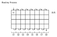
以下、図1のビットインターリーバ120の一例について図3を参照して説明する。なお、図3のビットインターリーバに含まれる並列ビットインターリーバと類似する並列ビットインターリーバを開示する文献として、例えば、(特許文献5参照)がある。
ビットインターリーバ120はQC LDPC符号の構造に特に適合した並列ビットインターリーバ121を含む。但し、図3における、QC LDPC符号語は、1符号語当たり12巡回ブロック、1巡回ブロック当たり8ビット(Q=8)である。なお、本件書類では、1符号語当たりの巡回ブロック数を「N」と表記する。
なお、説明を容易にするために、≪発明者らによる検討及びそれから発明者らが得た知見≫では、1QC LDPC符号語のN個の巡回ブロックが互いに同数の巡回ブロックを含むセクションに分けられる場合、つまりNが後述するMの倍数である場合について説明する。また、Qが2の倍数であるとして説明する。例えば、DVB-T2などでは、Q=360である。
1QC LDPC符号語の複数の巡回ブロックは複数のセクションに分けられ、各セクションはセクションパーミュテーションを使って別々にインターリーブされる。1セクション当たりの巡回ブロック数は、並列ビットインターリーバ121のパラメータであり、本件書類では、1セクション当たりの巡回ブロック数を「M」と表記する。なお、図3の例では、M=4である。
図3の例では、QC LDPC符号語のN=12個の巡回ブロックQB1~QB12がN/M=12/4=3個のセクションIS1~IS3に分けられる。セクションIS1~IS3のQ×M=8×4=32ビットは、並列ビットインターリーバ121のセクションインターリーバ121-1~121-3によってセクションパーミュテーションを使って別々にインターリーブされる。なお、インターリーブはコンステレーショングループC1~C24の夫々のM=4ビットに、それが対応するセクションに含まれるM=4個の巡回ブロックのそれぞれから1ビットずつマッピングされるように行われる。
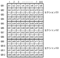
以下、M=4、Q=8の場合のセクションインターリーバ121-1によるセクションパーミュテーションの一例について図3のセクションIS1を対象として図4を用いて説明する。
セクションインターリーバ121-1は、図4に示すように、巡回ブロックQB1~QB4のQ×M=8×4=32ビットが、M=4ビットからなるQ=8個のコンステレーショングループC1~C8にマッピングされるように、ビットのインターリーブを実行する。
さらに、M=4、Q=8の場合のセクションインターリーバ121-1によるセクションパーミュテーションの一例について図3のセクションIS1を対象として図5A,Bを用いて更に詳細に説明する。図5A,Bの1つの四角は符号語の1ビットに対応する。
セクションインターリーバ121-1は、次の処理と等価な処理を行う。
セクションインターリーバ121-1は、セクションIS1のQ×M=8×4=32ビットを、入力されるビット順に、図5Aに示すようにM行Q列=4行8列のインターリーバ行列に行方向(row by row)に書き込む。そして、図5Bに示すように書き込んだQ×M=8×4=32ビットをこのインターリーバ行列から列方向(column by column)に読み出し、読み出した順に出力する。なお、図5A,Bには夫々書き込み順及び読み出し順が矢印で示されている。
なお、セクションインターリーバ121-2,121-3によるセクションパーミュテーションに関して、図4、及び図5A,Bで説明したセクションパーミュテーションの内容を適用できる。
上述したセクションパーミュテーションが実行されることによって、セクションインターリーバ121-1~121-3の夫々の出力は、それぞれがM=4ビット(インターリーバ行列の1列のビット)からなるQ=8個のコンステレーショングループからなり、各コンステレーショングループのM=4ビットは、元のLDPCブロックのM=4個の異なる巡回ブロックに属する。
好ましくは、Mは、後述するD次元ベクトル(D次元コンステレーションブロック)のD個のPAMシンボルの基となるビット数であり、例えば、M=B×Dである。
なお、図3の並列ビットインターリーバは、複数のセクションの夫々にセクションインターリーバを備えている。この代わりに、並列ビットインターリーバは、セクション数より少ない数のセクションインターリーバを備え、備えているセクションインターリーバを時分割で使用して複数のセクションに対して別々にセクションパーミュテーションを実行するようにしてもよい。
なお、複数の巡回ブロックを複数のセクションに分ける前に、QC LDPC符号語における複数の巡回ブロックの並び順を所定のパーミュテーションに従って変更してもよい。なお、当該パーミュテーションは、巡回ブロックパーミュテーション(QBパーミュテーション)と呼ばれる。
さらに、各巡回ブロックの夫々において、巡回ブロックにおけるQ個のビットの並び順を所定のパーミュテーション規則を用いて変更してもよい。なお、当該パーミュテーションは、巡回ブロック内パーミュテーション(Intra QBパーミュテーション)と呼ばれ、Intra QBパーミュテーションには通常巡回シフトが用いられる。シフト値は、通常、各巡回ブロックで互いに異なるが、少なくとも一部の巡回ブロックにおいて同じシフト値が用いられてもよい。
図6は、QBパーミュテーションとIntra QBパーミュテーションの機能を備えるビットインターリーバの一構成例を示すブロック図である。
ビットインターリーバ120Aは、セクションパーミュテーションを実行するセクションインターリーバ121に加え、その前段にQBパーミュテーションを実行するQBインターリーバ123、及び、Intra QBパーミュテーションを実行するIntra QBインターリーバ125-1~125-12を備えている。
なお、QBパーミュテーション及びIntra QBパーミュテーションのうち何れか一方のみを行うとしてもよく、それらの実行順序が逆であってもよい。
また、図6のビットインターリーバは、複数の巡回ブロックの夫々にIntra QBインターリーバを備えている。この代わりに、ビットインターリーバは、セクション数より少ない数のIntra QBインターリーバを備え、備えているIntra QBインターリーバを時分割で使用して複数の巡回ブロックに対して別々にIntra QBパーミュテーションを実行するようにしてもよい。
QBパーミュテーション及びIntra QBパーミュテーションは、通信性能の最適化にとって重要であるが、本開示には直接関連しない。事実、QBパーミュテーション及びIntra QBパーミュテーションはQC LDPC符号の定義の一部とみなすことができる。
QBパーミュテーションは元のPCMにおける巡回ブロックの列(図2の場合、巡回ブロック1列は行列要素8列に対応)のパーミュテーションと等価である。また、Intra QBパーミュテーションにおける巡回シフトは、PCMにおける元の巡回シフトされた対角線を(qmodQ)分さらに巡回シフトする、ことと等価である。但し、qはIntra QBパーミュテーションでQビットを巡回させるシフト値である。PCMの同じ列における全ての巡回ブロックの全対角線に対して同じシフト値が適用される。
以下、図1のコンステレーションローテータ150によるD次元空間における回転コンステレーションについて記載する。
回転コンステレーションは、深いフェージングや消失を伴う伝送路において、通信システムのロバスト性向上のための効果的なツールである。回転コンステレーションの基本的な考え方は、一つのバイナリ情報を複数のコンポーネントを使用して一斉に送信することによって信号空間のダイバーシティを作り出すことである。
これを達成するために、コンステレーションローテータ150は以下の処理を行う。
コンステレーションローテータ150は、コンポーネントデインターリーバ140の各セクションから出力されるD×Q個のPAMシンボルを、連続して出力されるD個のPAMシンボルのグループに分ける。そして、コンステレーションローテータ150は、グループの夫々において、D個のPAMシンボルを各次元の値とするD次元ベクトルをD行D列の正方直交行列に乗算する(回転処理)。つまり、正方直交行列と乗算されるD次元ベクトルをVD、D行D列の正方直交行列をMD,D、乗算の結果得られるD次元ベクトル(D次元回転ベクトル)をV’Dとした場合、コンステレーションローテータ150は、V’D=MD,DVDを計算する。なお、D次元ベクトルは、例えば、M=B×Dの場合、ビットインターリーバのセクションインターリーバのインターリーバ行列の1列分のMビットから作られる。
但し、Dは2の累乗であることが好ましく、例えば2、4である。
なお、ここで使用されるD行D列の正方直交行列は、D次元ベクトルの各次元の値が、D次元回転ベクトルの少なくとも2つの次元の値に分散されるようになる、行列である。
このような直交行列として、例えば、主対角線上にある全要素の絶対値の値が実数値aに等しく、主対角線上にない全要素の絶対値がゼロでない実数値bに等しい行列を挙げることができる。但し、主対角線とはi行i列(i=1~D)からなる対角線である。なお、この行列の行を並び替えたもの、列を並び替えたもの、行と列の双方を並び替えたものを直交行列として使用することができる。
図1のコンポーネントインターリーバ160は、
(1)D次元回転コンステレーションブロックのD個の回転PAMシンボル(回転コンポーネント)がインターリービング期間でできるだけ均等に分散され、
(2)時間-周波数スライシング(time-frequency slicing:TFS)の場合には、D次元回転コンステレーションブロックのD個の回転PAMシンボルが、取り得るRFチャネルの全てにマッピングされる、
ことを保証する必要がある。なお、両者の条件(1)、(2)を満たすことができない場合には、前者の条件(1)を犠牲にして、後者の条件(2)を保証することが望ましい。
(1)D次元回転コンステレーションブロックのD個の回転PAMシンボル(回転コンポーネント)がインターリービング期間でできるだけ均等に分散され、
(2)時間-周波数スライシング(time-frequency slicing:TFS)の場合には、D次元回転コンステレーションブロックのD個の回転PAMシンボルが、取り得るRFチャネルの全てにマッピングされる、
ことを保証する必要がある。なお、両者の条件(1)、(2)を満たすことができない場合には、前者の条件(1)を犠牲にして、後者の条件(2)を保証することが望ましい。
以下、図1のコンポーネントデインターリーバ140、コンポーネントインターリーバ160、セルインターリーバ170の一例について説明する。
コンポーネントインターリーバ160は、ビットインターリーバ120のセクションと1対1の対応関係にあるセクションの夫々において、次の処理と等価なコンポーネントインターリービングを行う。
コンポーネントインターリーバ160は、コンステレーションローテータ150の回転PAMシンボルの出力順に、回転PAMシンボルを回転コンポーネントとして、D×Q個の回転コンポーネントをD行Q列のインターリーバ行列に列方向に書き込む。なお、このインターリーバ行列の1列のD個の回転コンポーネントは同じ1つのD次元回転コンステレーションブロックに含まれるものである。
そして、コンポーネントインターリーバ160は、インターリーバ行列の各行を巡回シフトする。但し、インターリーバ行列の1行目のシフト値を0とし、1つ前の行に適用する巡回シフトよりシフト値がQ/D PAMシンボル増加した巡回シフトが、インターリーバ行列の各行に適用される。
そして、コンポーネントインターリーバ160は、巡回シフト後のインターリーバ行列から回転コンポーネントを行方向に読み出し、読み出した順に回転コンポーネントを出力する。連続して出力される2つの回転コンポーネントは、夫々を実数コンポーネント及び虚数コンポーネントとする1つのセルにマッピングされて順次セルインターリーバ170に供給される。このようにコンポーネントインターリービングが行われることによって、コンポーネントインターリービング後のD次元回転コンステレーションブロックのD個の回転コンポーネントの広がりは非常に均等になる。
セルインターリーバ170は、入力順に、(N/M)×D×(Q/2)個のセルを(N/M)×D行Q/2列のインターリーバ行列に行方向に書き込み、インターリーバ行列からセルを列方向に読み出し、読み出した順にセルを出力する、ことと等価なセルインターリービングを行う。
ここで、上述したコンポーネントインターリーバ160に対するコンポーネントデインターリーバ140の動作を説明する。
コンポーネントデインターリーバ140は、ビットインターリーバ120のセクションと1対1の対応関係にあるセクションの夫々において、次の処理と等価なコンポーネントデインターリービングを行う。
コンポーネントデインターリーバ140は、PAMマッパ130のPAMシンボルの出力順に、PAMシンボルをコンポーネントとして、D行Q列のインターリーバ行列に列方向に書き込む。
そして、コンポーネントデインターリーバ140は、インターリーバ行列の各行を巡回シフトする。但し、インターリーバ行列の1行目のシフト値を0とし、1つ前の行に適用する巡回シフトよりシフト値が-Q/D PAMシンボル減少した巡回シフトが、インターリーバ行列の各行に適用される。このように、コンポーネントデインターリーバ140による巡回シフトとコンポーネントインターリーバ160による巡回シフトとは正確に反対になっている。
そして、コンポーネントデインターリーバ140は、巡回シフト後のインターリーバ行列からコンポーネントを列方向に読み出し、読み出した順にコンポーネントを出力する。
なお、コンポーネントデインターリーバ140又はコンポーネントインターリーバ160は、セクション毎にインターリーバを備えて、コンポーネントデインターリービング又はコンポーネントインターリービングを行うようにしてもよい。
また、コンポーネントデインターリーバ140又はコンポーネントインターリーバ160は、セクション数より少ない数のインターリーバを備え、備えているインターリーバを時分割で使用して複数のセクションに対して別々にコンポーネントデインターリービング又はコンポーネントインターリービングを行うようにしてもよい。
以下、時間-周波数スライシング(time-frequency slicing:TFS)について説明する。
TFSは、複数のRFチャネルを用いて有効にダイバーシティ(以下、「チャネルダイバーシティ」と適宜記載する。)を活用する、深いフェージングや消失を伴う伝送路において、通信システムのロバスト性向上のための効果的なツールである。
チャネルダイバーシティの主要な類型として、周波数ダイバーシティがある。周波数ダイバーシティは、無線チャネルにおけるフェージングが周波数選択性を有する傾向にあり、従って任意の2つのRFチャネル間のフェージングの相関は相対的に低い、という事実に起因する。さらに、異なるRFチャンネルを用いる送信機が異なる地理上の位置に配置されている場合、いわゆる空間ダイバーシティが活用される。従って、チャネルダイバーシティは、周波数ダイバーシティと空間ダイバーシティの双方に起因する。
複数のRFチャネルを用いる通信システムにおいて、受信機において一つのチューナで受信を可能にするために、連続的に受信される情報、例えば一つの放送番組が、常に複数のRFチャネルで送信されてはならない。このため、周波数の切り替えとタイムスライスのシーケンス、即ち、TFSスケジューリング(a time-frequency slicing schedule)を用いる必要がある。受信機は、TFSスケジューリングに基づいて、複数のRFチャネル間でRFチャネルを切り替えながら、適切なスライスの期間で各RFチャネルから所望のデータを抽出することができる。TFSスケジューリング(時間-周波数配置)は通常専用のシグナリング情報を用いて受信機に通知される。
図7にTFSスケジューリングの一例を示す。但し、RFチャネル数が3、TFSサイクル数が3である。図7の一例では、9個のスライスが、RFチャネルRF1、RF2、RF3の順番を繰り返しながら、順番にRFチャネルに配置されていく。なお、受信機のチューナがRFチャネル間を切り替えながらスライスを受信することができるようにするために、2つの連続するスライス間にガード期間を挿入することが要求される。
以下では、TFS多重におけるRFチャネルの数をNRFと表記し、1つのLDPCブロックが分散されるTFSサイクル数をNCと表記する。1つのFECブロックが分散されるスライスの数をNSと表記すると、NS=NRF×NCとなる。
最適なダイバーシティは、全スライスが同じ長さで、各LDPCブロックが全スライスで同数のセルを有する場合に、達成される。
図8に、FECブロックのスライシングの一例を示す。但し、RFチャネル数が3、TFSサイクル数が3であり、図7のTFSスケジューリングの一例に対応する。スライシング処理は単純である。図8の一例では、スケジューラ180はセルインターリーバ170から出力される複数のセルを、連続して出力されるセルが同じスライスに含まれるように、NS=NRF×NC=3×3=9個のスライスにスライシングする。
回転コンステレーションがTFSとともに用いられる場合、D次元回転コンステレーションブロックのD個の回転PAMシンボル(回転コンポーネント)はRFチャネルにできるだけ均等にマッピングされる必要がある。例えば、D=2の場合、2次元回転コンステレーションブロックの2個の回転コンポーネントが、RFチャネルの全ての可能なペアにマッピングされる必要がある。例えば、RFチャネル数が3の場合、RFチャネルのインデックスを1、2、3とすると、RFチャネルのペアは(1,2)、(1,3)、(2,3)である。2次元回転コンステレーションブロックの2個のコンポーネントが同じRFチャネルにマッピングされることは避けなければならない。
以下、上述したコンステレーションローテータ150、コンポーネントインターリーバ160、セルインターリーバ170をTFSに適用した場合の問題点について図面を参照して説明する。
図9は図1の送信機の構成の一部を示すブロック図であり、PAMマッパ130、コンステレーションローテータ150、コンポーネントインターリーバ160、セルインターリーバ170が示されている。但し、D=2、B=2である。なお、図1ではPAMマッパ130とコンステレーションローテータ150との間にコンポーネントデインターリーバ140が配置されている。しかしながら、コンポーネントデインターリーバ140は、上述したユニットをTFSに適用した場合の問題点を説明する上で特に関係していないため、図9では説明の簡易化のため省略している。
PAMマッパ130の前段のビットインターリーバにおけるビット配置を図10に示す。但し、図10のビット配置は図3から図5を用いて説明したビットインターリーバ120に対応し、N=12、Q=8、M=D×B=2×2=4である。なお、図10の1つの四角は1ビットに対応し、四角内のbのインデックスはビットの入力の順番を示す。
図10のビット配置において、各セクションIS1~IS3の各列の4ビットが1つの2次元回転コンステレーションブロックの基となるビット群である。
PAMマッパ130は、セクションインターリーバ121-1~121-3から出力される連続するB=2個のビット(b1、b9)、(b17、b25)、(b2、b10)、(b18、b26)、・・・を順にPAMシンボルPAM1、PAM2、PAM3、PAM4、・・・にマッピングして出力する。
コンステレーションローテータ150は、連続する2×D=2×2=4個のPAMシンボルからなるグループの夫々において、順番に、次の処理を行う。ここでは、連続するD=4個のPAMシンボルPAM1、PAM2、PAM3、PAM4からなるグループについて記載する。コンステレーションローテータ150は、2次元ベクトル(PAM1、PAM2)をD行D列=2行2列の正方直交行列に乗算し、その結果得られる2次元回転ベクトルの回転PAMシンボルPAM1r、PAM2rを順番に出力する(第1回転処理)。続いて、コンステレーションローテータ150は、2次元ベクトル(PAM3、PAM4)をD行D列=2行2列の正方直交行列に乗算し、その結果得られる2次元回転ベクトルの回転PAMシンボルPAM3r、PAM4rを順番に出力する(第2回転処理)。これと同様の処理が各グループにおいて行われる。
コンポーネントインターリーバ160は、ビットインターリーバ120のセクションIS1~IS3と1対1の対応関係にあるセクションの夫々において、次の処理を行う。コンポーネントインターリーバ160は、コンステレーションローテータ150の回転PAMシンボルの出力順に、回転PAMシンボルを回転コンポーネントとして、D×Q個の回転コンポーネントをD行Q列=2行8列のインターリーバ行列に列方向に書き込む。この結果、コンポーネントインターリーバ160における回転コンポーネントの配置は図11Aに示すものとなる。なお、図11A及び後述する図11Bの1つの四角は1つの回転コンポーネントに対応し、四角内の数字は回転コンポーネントの入力の順番を示す。ハッチされた回転コンポーネントは後にセルの実数コンポーネントにて送信され、ハッチされていないコンポーネントは後にセルの虚数コンポーネントにて送信される。
コンポーネントインターリーバ160は、セクションIS1~IS3の夫々において、そのD=2行目の行に対してQ/D=8/2=4個の回転コンポーネント分巡回シフトを行う。この結果を図11Bに示す。なお、図11Bでは、図11Aの各セクションIS1~IS3の1列目に配置された回転コンポーネントに対してハッチをいれている。
コンポーネントインターリーバ160は、セクションIS1~IS3の夫々において、巡回シフト後のD行Q列=2行8列のインターリーバ行列から回転コンポーネントを行方向に読み出し、読み出した順に出力する。連続して出力される2個の回転コンポーネントは、夫々を実数コンポーネント及び虚数コンポーネントとする1つのセルにマッピングされて順次セルインターリーバ170に供給される。
セルインターリーバ170は、セルを入力順にD×(Q/2)×(N/M)=2×(8/2)×(12/4)=24個のセルを、(N/M)×D行Q/2列=(12/4)×2行8/2列=6行4列のインターリーバ行列に行方向に書き込み、インターリーバ行列からセルを列方向に読み出し、読み出した順にセルを出力する。なお、セルインターリーバ170における書き込み時のセルの配置は図12に示すものとなる。なお、図12の1つの四角は1セルに対応し、四角内の数字はセルの入力の順番を示す。また、ここで説明しようとしている問題点を分かりやすくするために、図11Bに同じハッチを入れた2つの回転コンポーネントを夫々実数コンポーネントとする2つのセルには同じハッチを入れている。つまり、例えば、2次元回転コンステレーションブロックの2個の回転コンポーネント1、2を実数コンポーネントとするセル1、7に、回転コンポーネント1、2と同じハッチを入れている。
例えば、2RFチャネル、2TFSサイクルのTFS(NRF=NC=2)の場合、スケジューラ180は、(N/M)×D×(Q/2)=(12/4)×2×(8/2)=24個のセルを、夫々がセルインターリーバ170から連続して出力される(N/M)×D×(Q/2)/(NRF×NC)=24/(2×2)=6個のセルを含むように、NRF×NC=2×2=4個のスライスに分ける。そして、スケジューラ180は、NRF×NC=2×2=4個のスライスを、RFチャネRF1、RF2の順番を繰り返しながら、RFチャネルに割り当てる。この結果を図13に示す。なお、図13は図12に対応する。
例えば、一つの2次元回転コンステレーションブロックの2個の回転PAMシンボル(回転コンポーネント)に対応する、セル1の実数コンポーネントとセル7の実数コンポーネントは、同じRFチャネルRF1で送信される。仮に、RFチャネルRF1が深いフェージングの影響を受ける場合、2次元回転コンステレーションブロックの2個の回転PAMシンボルが失われる、つまり、2次元回転コンステレーションブロック全体が失われてしまう。
このように、TFSの場合、D、NRF、NCのパラメータの組み合わせによっては、D次元回転コンステレーションブロックのD個の回転PAMシンボルが同じRFチャネルにマッピングされ、D次元回転コンステレーションブロック全体が失われてしまう、ことがある。
従って、D次元回転コンステレーションのD個の回転PAMシンボルができるだけ多くのRFチャネル上に分散されることが必要である。
そこで、発明者らはどのようにすればD次元回転コンステレーションブロックの回転PAMシンボルをできるだけ多くのRFチャネル上に分散させることができるかを考察した。
この際、発明者らは、図11A、Bにおいて同じ行の連続する2列のコンポーネントを実数コンポーネント及び虚数コンポーネントとする1つのセルに置き換えを行った。この場合、図11Aに対応するコンポーネントインターリーバにおける書き込み時のセル配置は図14Aに示すものとなり、図11Bに対応するコンポーネントインターリーバにおける巡回シフト後のセル配置は図14Bに示すものとなる。但し、セクションIS1~IS3の夫々において、1行目の巡回シフト値は0、2行目の巡回シフト値は(Q/2)/D=(8/2)/2=2セルである。
図14Aから分かる通り、セクションIS1~IS3の夫々の2行目の巡回シフト値として0以上Q/2-1=8/2-1=3以下の値(単位セル)、即ち、1セル、2セル、3セルを取り得る。そして、図14Bから分かる通り、巡回シフト値(Q/2)/D=(8/2)/2=2セルは、2次元回転コンステレーションブロックの全回転コンポーネントが同じRFチャネルに配置されてしまう。
しかしながら、セクションIS1~IS3の夫々の2行目の巡回シフト値を、1セルを除いた巡回シフト値1セル、3セルから選択するとする。図15の例では、巡回シフト値は、セクションIS1では1セル、セクションIS2では3セル、セクションIS3では1セルである。この場合のTFSの結果は図16に示すものとなり、2次元回転コンステレーションブロックの2個の回転コンポーネントが異なるRFチャネル上に分散される。例えば、一つの2次元回転コンステレーションブロックの2個の回転コンポーネントに対応するセル1の実数コンポーネントとセル5の実数コンポーネントは夫々RFチャネルRF1とRFチャネルRF2で送信される、などである。従って、仮にRFチャネルの1つが深いフェージングを受けている場合でも、2次元回転コンステレーションブロックは、他のRFチャネルにより、十分にデコードされ得る。
この考察の結果、発明者らは、巡回シフト値を適切に選ぶことによってD次元回転コンステレーションブロックのD個の回転コンポーネントをできるだけ多くのRFチャネルに配置することが可能であることが分かった。
コンポーネントインターリーバ160が例えば図11Aに示すD行Q列のインターリーバ行列に対して巡回シフトを行う場合、巡回シフト値として0以上Q-1以下の値を取り得る。コンポーネントインターリーバ160は、D次元回転ブロックのD個の回転PAMシンボルをできるだけFECブロックに均等に分散されるように、各行に対して選ばれた巡回シフト値を用いて巡回シフトを実行するものである。好ましくは、巡回シフト値はセルの粒度、即ち、2の倍数である。
≪実施の形態≫
以下、本開示の実施の形態に係る送信機について図面を参照しつつ説明する。
以下、本開示の実施の形態に係る送信機について図面を参照しつつ説明する。
図17は、本開示の実施の形態に係る送信機の一構成例を示すブロック図である。
図17の送信機100Aは、図1の従来の送信機100のコンポーネントデインターリーバ140をコンポーネントデインターリーバ140Aに置き換え、コンポーネントインターリーバ160及びセルインターリーバ170をコンポーネントインターリーバ160Aに置き換えた構成をしている。なお、図17の送信機100Aにおいて、図1の送信機100の構成要素と実質的に同じ機能又は動作を行う構成要素には同じ符号を付し、その説明が適用できるためここではその説明を省略する。
なお、≪実施の形態≫では、1LDPCブロックの巡回ブロック数Nが1つのセクションに含まれる巡回ブロック数Mの倍数であるとし、Dは2の累乗(例えば、2、4)、M=B×Dであるとして説明する。
コンポーネントインターリーバ160Aは、ビットインターリーバ120の(N/M)個のセクションと1対1の対応関係にある各セクションにおいて、コンステレーションローテータ150からの回転PAMシンボルの入力順に、回転PAMシンボルを回転コンポーネントとし、D×Q個の回転コンポーネントをD行Q列のインターリーバ行列に列方向に書き込む。
そして、コンポーネントインターリーバ160Aは、各セクションにおいて、D行Q列のインターリーバ行列の同じ行の隣り合う2列の実数値の回転コンポーネント(回転PAMシンボル)を、夫々を実数コンポーネント及び虚数コンポーネントとする、1つのセルとし、実数値の回転コンポーネントを要素とするインターリーバ行列を、複素値のコンポーネント(セル)を要素とするD行(Q/2)列のインターリーバ行列(以下、「複素インターリーバ行列」と記載する。)に変換する。
そして、コンポーネントインターリーバ160Aは、N/M個のD行(Q/2)列の複素インターリーバ行列を列方向に並べる(ある複素インターリーバ行列の最後の行の次に、他の複素インターリーバの行列の最初の行が来るように並べる)。このようにして、N/M個のD行(Q/2)列の複素インターリーバ行列を結合して、(N/M)×D行(Q/2)列の複素インターリーバ行列(以下、「結合複素インターリーバ行列」と記載する。)とする。
コンポーネントインターリーバ160Aは、結合複素インターリーバ行列の各行に対して巡回シフトを行う。コンポーネントインターリーバ160Aが行う巡回シフトについては後に詳述する。
コンポーネントインターリーバ160Aは、巡回シフト後の結合複素インターリーバ行列からセルを列方向に読み出し、読み出した順に出力する。
なお、スケジューラ180は、コンポーネントインターリーバ160Aから出力される(N/M)×D×(Q/2)個のセルをNRF×NC個のスライスに分割する。そして、スケジューラ180は、NRF個のRFチャネルRF1、RF2、RF3、・・・の順番を繰り返しながら、NRF×NC個のスライスを順番にRFチャネルに配置していく。
但し、TFSサイクル数NCは1つの符号語を送信する場合のNRF個のRFチャネルの集合間での変化数である。NC=1の場合、全RFチャネルは一回スキャンされる(NRF=3の場合、RF1→RF2→RF3)、NC=2の場合、全RFチャネルは2回スキャンされる(NRF=3の場合、RF1→RF2→RF3→RF1→RF2→RF3)である。
コンポーネントデインターリーバ140Aは、ビットインターリーバ120の(N/M)個のセクションと1対1の対応関係にあるセクションの夫々において、次の処理を行う。
コンポーネントデインターリーバ140Aは、PAMマッパ130からのPAMシンボルの入力順に、PAMシンボルをコンポーネントとし、D×Q個のコンポーネントをD行Q列のインターリーバ行列に列方向に書き込む。
そして、コンポーネントデインターリーバ140Aは、各セクションのD行Q列のインターリーバ行列において、各行に対して、当該行に対してコンポーネントインターリーバ160Aが巡回シフトに用いるセル単位のシフト値に対して(-1)×2を乗算した値をPAMシンボル単位のシフト値とする巡回シフトを行う。
なお、この巡回シフト処理は、同じ行の連続する2列のPAMシンボル(実数値のコンポーネント)を1つの複素値のコンポーネント(セル)とし、実数値のD行Q列のインターリーバ行列を複素値のD行Q/2列のインターリーバ行列とみなした場合、次の巡回シフトと等価である。コンポーネントデインターリーバ140Aは、各セクションのD行Q/2列のインターリーバ行列において、各行に対して、当該行に対してコンポーネントインターリーバ160Aが巡回シフトに用いるシフト値に対して(-1)を乗算した値をセル単位のシフト値とする巡回シフトを行う。
コンポーネントデインターリーバ140Aは、巡回シフト後のD行Q列のインターリーバ行列からコンポーネントを列方向に読み出し、読み出した順に出力する。
以下、コンポーネントインターリーバ160Aが結合複素インターリーバ行列において行う巡回シフトについて記載する。なお、ここでは、巡回シフトのシフト値について、実数値のPAMシンボルの代わりに複素QAMシンボル(複素値のセル)を用いて言及する。
コンポーネントインターリーバ160Aによる巡回シフトは、W=floor (Q/max{D,(NRF×NC)}/2)セルを単位として行われる。但し、Wを巡回シフト幅と表記する。なお、関数floor(x)はx以下の最大の整数を返す関数である。
全ての可能な巡回シフト値の集合は{0,W,2×W,・・・,(max{D,(NRF×NC)}-1)×W}である。
但し、パラメータの組み合わせによっては、最後のスライスのスライス幅が他のスライスのスライス幅と異なることがある。これが起こるのは、Q/2がNRF×NCの約数でなく(例えばQ=360、NRF=NC=4)の場合である。このような場合には、例えば、最後のスライス以外の全てのスライスの結合複素インターリーバ行列における列幅は、floor {Q/(NRF×NC)/2}セルである。また、最後のスライスの結合複素インターリーバ行列における列幅は、[Q/2-(NRF×NC-2)×floor {Q/(NRF×NC)/2}]/2セルである。なお、この記載は、NRF×NCがQ/2の約数の場合でも利用できる。
ここで、コンポーネントインターリーバ160Aが実際に使用する巡回シフト値として、上記の全ての可能な巡回シフト値の集合{0,W,2×W,・・・,(max{D,(NRF×NC)}-1)×W}からどのように選ぶかについて記載する。
なお、巡回シフト値はk×W(但し、k=0~max{D,(NRF×NC)}-1)と記載できるため、以下では、記載の簡略化のため、集合{0,1,2,・・・,max{D,(NRF×NC)}-1からWの係数kをどのようにして選ぶかに置き換えて記載する。
まず、結合複素インターリーバ行列の1つのセクションに対応するD行では、その先頭行から最終行の夫々の巡回シフトに適用するWの係数kの値の集合(以下、「セクション使用集合」と記載する。)として、0以上(max{D,(NRF×NC)}-1)以下の整数の中から、
NRF≧Dの場合、
k mod NRFによって得られる異なる整数の値の個数が2以上D以下となるように、
NRF<Dで、NRF×NC≧Dの場合、
k mod NRFによって得られる異なる整数の値の個数が2以上NRF以下となるように、
NRF<Dで、NRF×NC<D、a×NC≠b×Dである場合、
k mod Dによって得られる異なる整数の値の個数が2以上D以下となるように、
NRF<Dで、NRF×NC<D、a×NC=b×Dである場合、
k mod Dによって得られる異なる整数の値の個数が2以上D以下で、少なくとも2個のkの差はa/bの倍数でないものと含むように、
D個のkの値を選ぶ。なお、例えば、D=4の場合に{0,0,1,NRF}がセクション使用集合となるなど、セクション使用集合のD個のkには、同じ値のkが含まれていてもよいし、k mod NRFやk mod Dの値が同じになる異なる値のkが含まれていてもよい。
コンポーネントインターリーバ160Aは、D行の夫々に対して、当該行に適用するWの係数の値とWとを乗算した乗算値(単位セル)を巡回シフト値として用いて巡回シフトを行う。
なお、k mod NRFによって得られる異なる値の整数の個数が2の場合、D次元回転コンステレーションブロックは2つのRFチャネルを用いて伝送されることになる。また、NRF≧Dの場合、k mod NRFによって得られる異なる値の整数の個数がDの場合には、D次元回転コンステレーションブロックはD個のRFチャネルを用いて伝送されることになる。また、NRF<Dで、NRF×NC≧Dの場合、k mod NRFによって得られる異なる整数の値の個数がNRFの場合には、D次元回転コンステレーションブロックはNRF個のRFチャネルを用いて伝送されることになる。このように、K mod NRFによって得られる異なる値の数が多い程、より多くのRFチャネルでD次元回転コンステレーションブロックが送信されることになる。
上記NRF≧Dの場合又はNRF<Dで、NRF×NC≧Dの場合以外の場合で、k mod Dによって得られる異なる整数の値の個数がDの場合、D次元回転コンステレーションブロックはD個のRFチャネルを用いて伝送されることになる。k mod Dによって得られる異なる値の数が多い程、より多くのRFチャネルでD次元回転コンステレーションブロックが送信されることになる。
また、上記の異なる整数の値の個数が最大になるように選んだセクション使用集合のD個のkの値を、k mod NRF、k mod Dによって得られる同じ整数の値の個数ができるだけ均等になるように選んでもよい。この場合には、D次元回転コンステレーションブロックのD個の回転コンポーネントがNRF個のRFチャネルにできるだけ均等に分散されることになる。
例えば、D≦NRFでD=2の場合、1つのセクションに対応する2行では、kの値がk mod NRF=0を満たす値、k mod NRF≠0を満たす値、の行が夫々1つ存在するようにする。
また、D≦NRFでD=4の場合、1つのセクションに対応する4行では、kの値がk mod NRF=0を満たす値、k mod NRF=Lを満たす値、kの値がk mod NRF=Mを満たす値、及びk mod NRF=Nを満たす値、の行が夫々1つ存在するようにする。但し、L、M、Nは互いに異なる1以上の整数である。
上記の結合複素インターリーバ行列の1つのセクションに対応するD行に対するWの係数kの選び方に加えて、次のようなWの係数kの選び方を追加してもよい。結合複素インターリーバ行列の複数のセクションにおいて、集合{0,1,2,・・・,(max{D,(NRF×NC)}-1)}が少なくとも1回Wの係数kとして選ばれるようにする。
なお、D次元回転コンステレーションブロックのD個のコンポーネントを周波数と時間とでできるだけ均等に分離することにより最大の効果が得られる。
上述の巡回シフト値の割り当て方に基づいたD=2、4の夫々に対する巡回シフトパターンの具体例を表1、表2に示す。但し、RFチャネル数NRF、TFSサイクル数NCに対する、W=floor (Q/max{D,(NRF×NC)}/2)セルを単位とする。なお、表1、表2には、巡回シフトパターンとしてフルシフトパターンとショートシフトパターンが記載されている。
ショートシフトパターンは、時間におけるD次元回転コンステレーションブロックのD個の回転コンポーネントの分散が小さくなるように、フルシフトパターンに変更を加えたものである。
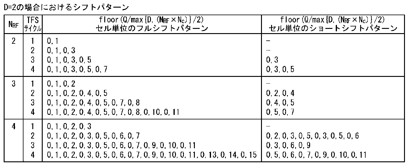
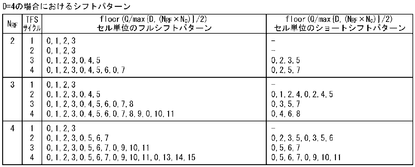
表1、表2において、NRF≧Dの場合、フルシフトパターンでは、各セクションの先頭の行に対する巡回シフト値は0、それ以外の行の巡回シフト値はNRFの倍数を除く1から(NRF×NC)-1の値が順番に並ぶようになっている。
また、NRF<Dの場合、フルシフトパターンでは、各セクションの先頭の行に対する巡回シフト値は0、それ以外の行の巡回シフト値は1からmax{D,(NRF×NC)}-1の値が順番に並ぶようになっている。
ここで、表1、表2のフルシフトパターンとコンポーネントインターリーバ160Aが巡回シフトに用いる巡回シフト値との関係について記載する。
コンポーネントインターリーバ160Aは、結合複素インターリーバ行列全体の各セクションの先頭の行(行インデックスをiとした場合、i mod D=1の行)では、フルシフトパターンの{0}を使用し、巡回シフト値0×Wセルの巡回シフトを行う(巡回シフトしないことと等価)。
コンポーネントインターリーバ160Aは、結合複素インターリーバ行列全体の各セクションの先頭の行を除く各行では、フルシフトパターンの{0}を除くパターン内の値kを1つ目から順番に繰り返し使用し、巡回シフト値k×Wセルの巡回シフトを行う。つまり、結合複素インターリーバ行列全体から各セクションの先頭の行を除いた行列で見た場合、当該除いた行列の各行に対して、その先頭の行から順番に、フルシフトパターンから{0}を除外したパターン内の値の1つ目から繰り返し用いる。
例えば、D=4,NRF=2,NC=2、フルシフトパターンの場合は、次のようになる。
コンポーネントインターリーバ160Aは、1つ目のセクションの4行に対してその先頭の行から0、1、2、3に基づく巡回シフトを行う。続いて、2つ目のセクションの4行に対してその先頭の行から0、1、2、3に基づく巡回シフトを行う。以降、これと同様のことが繰り返し行われる。
例えば、D=4,NRF=3,NC=2、フルシフトパターンの場合は、次のようになる。
コンポーネントインターリーバ160Aは1つ目のセクションの4行に対してその先頭の行から0、1、2、3に基づく巡回シフトを行う。続いて、2つ目のセクションの4行に対してその先頭の行から0、4、5、1に基づく巡回シフトを行う。さらに続いて、3つ目のセクションの4行に対してその先頭の行から0、2、3、4を用いた巡回シフトを行う。さらに続いて、4つ目のセクションの4行に対してその先頭の行から0、5、1、2を用いた巡回シフトを行う。さらに続いて、5つ目のセクションの4行に対してその先頭の行から0、3、4、5を用いた巡回シフトを行う。以降、これと同様のことが繰り返し行われる。
なお、ショートシフトパターンでは、コンポーネントインターリーバ160Aは、ショートシフトパターンを繰り返して用いて、結合複素インターリーバ行列の各行に対して先頭の行から順番に割り当てていく。
図18A及び図18Bに、Q=16、D=2、NRF=2、NC=4、N/M=4の場合のコンポーネントインターリーバ160Aによるフルシフトパターン及びショートシフトパターンに基づく巡回シフト適用後の結合複素インターリーバ行列のセル配置を示す。但し、結合複素インターリーバ行列は(N/M)×D行Q/2列=8行8列である。なお、巡回シフト前の結合複素インターリーバ行列の1行目のセルに対してハッチを入れている。
NRF×NC=2×4=8はD=2より大きいため(NRF×NC>D)、W=floor (Q/max{D,(NRF×NC)}/2)セル=floor (Q/(NRF×NC)/2)セル=floor (16/(2×4)/2)セル=1セルとなる。
図18Aの例では、コンポーネントインターリーバ160Aは、表1のNRF=2、NC=4に対応するフルシフトパターンを使って、先頭行から、「巡回シフトなし」、「1セル巡回シフト」、「巡回シフトなし」、「3セル巡回シフト」、「巡回シフトなし」、「5セル巡回シフト」、「巡回シフトなし」、「7セル巡回シフト」を適用する。
図18Bの例では、コンポーネントインターリーバ160Aは、表1のNRF=2、NC=4に対応するショートシフトパターンを使って、先頭行から、「巡回シフトなし」、「3セル巡回シフト」、「巡回シフトなし」、「5セル巡回シフト」、「巡回シフトなし」、「3セル巡回シフト」、「巡回シフトなし」、「5セル巡回シフト」を適用する。
図18A、Bでは、フルシフトパターンとショートシフトパターンとにおけるシフト値の平均値はともに4で同じである。しかしながら、フルシフトパターン及びショートシフトパターンにおけるシフト値の分散は夫々6.667と2で、ショートシフトパターンにおける分散はフルシフトパターンにおける分散より小さい。
コンポーネントインターリーバ160Aの巡回シフトの動作を更に図19及び図20を用いて説明する。但し、図19A、図20Aは巡回シフト前の結合複素インターリーバ行列を示し、図19B、図20Bは巡回シフト後の結合複素インターリーバ行列を示す。なお、図19A,B、図20A,Bでは、セクションIS1~IS4の巡回シフト適用前の先頭列のセルのみ四角で示している。
図19A,BはD=4,NRF=3、NC=1におけるコンポーネントインターリーバ160Aによるフルシフトパターンを用いた場合の巡回シフトを説明するための図である。
D=4は、NRF×NC=3×1=3より大きい(D>NRF×NC)。なお、図の記載を簡単にするためにQ/2がDの倍数であるとする。W=floor (Q/max{D,(NRF×NC)}/2)セル=Q/D/2となる。
コンポーネントインターリーバ160Aは、表2のフルシフトパターンの場合、巡回シフト値k×Wのkの値として、各セクションの4行の夫々に対して0、1、2、3を選び、選択したkの値を基に巡回シフト値k×W分巡回シフトを行う。この結果、図19Aから図19Bに示すものとなる。
図20A,BはD=4,NRF=3、NC=2におけるコンポーネントインターリーバ160Aによる巡回シフトを説明するための図である。
NRF×NC=3×2=6は、D=4より大きい(NRF×NC>D)。なお、図の記載を簡単にするためにQ/2がNRF×NCの倍数であるとする。W=floor (Q/max{D,(NRF×NC)}/2)セル=Q/(NRF×NC)/2となる。
コンポーネントインターリーバ160Aは、表2のフルシフトパターンの場合、巡回シフト値k×Wのkの値として、1つ目のセクションの4行の夫々に対して0、1、2、3を選び、2つ目のセクションの4行の夫々に対して0、4、5、1を選び、3つ目のセクションの4行の夫々に対して0、2、3、4を選び、4つ目のセクションの4行の夫々に対して0、5、1、2と選ぶ。コンポーネントインターリーバ160Aは、選択したkの値を基に巡回シフト値k×W分巡回シフトを行う。この結果、図20Aから図20Bに示すものとなる。
但し、スケジューラ180は、コンポーネントインターリーバ160Aの出力であるセルを、夫々が連続して出力されるセルからなるNRF×NC個のスライスに分ける。そして、スケジューラ180は、NRF個のRFチャネルを順番に繰り返して用い、NRF×NC個のスライスを順番にRFチャネルに割り当てていく。
なお、最後のスライスを除く全スライスは結合複素インターリーバ行列のfloor {Q/(NRF×NC)/2}列分のセルからなる。また、最後のスライスは[Q/2-(NRF×NC-2)×floor {Q/(NRF×NC)/2}]/2列分のセルからなる。なお、この記載は、Q/2がNRF×NCの倍数の場合及び倍数でない場合の双方に利用できる。
以下、本開示の実施の形態における受信機について図面を参照しつつ説明する。
図21は本開示の実施の形態に係る受信機の一構成例を示すブロック図である。
受信機500は、図17の送信機100Aの機能を反映し、受信アンテナ510、RFフロントエンド520、コンポーネントデインターリーバ530、回転コンステレーションデマッパ540、コンポーネントインターリーバ550、ビットデインターリーバ560、及びLDPCデコーダ570を備える。
RFフロントエンド520は、TFSスケジューリング情報に従ってNRF個のRFチャネルから(N/M)×D×(Q/2)個の複素シンボル(セル)を取り出して出力する。
コンポーネントデインターリーバ530は、(N/M)×D×(Q/2)個のセルの並びを、送信機100Aのコンポーネントインターリーバ160Aによる並び替え前の並びに戻すための次の処理と等価な処理を行う。なお、コンポーネントデインターリーバ530に基づく処理はコンポーネントインターリーバ160Aによる並び替え規則と逆の並び替え規則を用いる。
コンポーネントデインターリーバ530は、RFフロントエンド520からの入力順に、(N/M)×D×(Q/2)個のセルを(N/M)×D行(Q/2)列の結合複素インターリーバ行列に列方向に書き込む。
続いて、コンポーネントデインターリーバ530は、結合複素インターリーバ行列の各行に対して、送信機100Aのコンポーネントインターリーバ160Aが行った巡回シフトと正確に反対の巡回シフトを行う(コンポーネントインターリーバ160Aが用いる巡回シフト値がAの場合、コンポーネントデインターリーバ530が用いる巡回シフト値は-A)。
そして、コンポーネントデインターリーバ530は、巡回シフト後の(N/M)×D行(Q/2)列の結合複素インターリーバ行列を(N/M)個のD行(Q/2)列の複素インターリーバ行列に分ける。つまり、(N/M)×D×(Q/2)個のセルを、夫々が、送信機100Aのビットインターリーバ120のセクションと1対1の対応関係にある、(N/M)個のセクションに分ける。そして、(N/M)個のセクションの夫々において、1つのセルの実数コンポーネントと虚数コンポーネントとを同じ行の連続する2列に配置されるように、D行(Q/2)列の複素インターリーバ行列をD行Q列の実数インターリーバ行列に変換する。
続いて、コンポーネントデインターリーバ530は、各セクションにおいて、D行Q列の実数インターリーバ行列から回転コンポーネントを列方向に読み出し、読み出した順に出力する。
回転コンステレーションデマッパ540は、各セクションにおいて、コンポーネントデインターリーバ530から入力された連続するD個のコンポーネントをグループにして順次デマッピングして(ソフト)ビットを取り出し、コンポーネントインターリーバ550へ出力する。なお、回転コンステレーションデマッパ540は、コンステレーションデローテータとQAMデマッピングを1つのブロックで行うものである。
コンポーネントインターリーバ550は、(N/M)×D×Q個のB(ソフト)ビットの並びを、送信機100Aのコンポーネントデインターリーバ140Aによる並び替え前の並びに戻すための次の処理と等価な処理を行う。なお、コンポーネントインターリーバ550に基づく処理はコンポーネントデインターリーバ140Aによる並び替え規則と逆の並び替え規則を用いる。また、B(ソフト)ビットがコンポーネントデインターリーバ140Aのコンポーネントに相当し、以下では、B(ソフト)ビットのグループを「(ソフト)ビットグループ」と記載する。
コンポーネントインターリーバ550は、コンポーネントデインターリーバ530のセクションと1対1の対応関係にあるセクションの夫々において、回転コンステレーションデマッパ540からの入力順に、Q×D個の(ソフト)ビットグループをD行Q列のインターリーバ行列に列方向に書き込む。そして、コンポーネントインターリーバ550は、送信機100Aのコンポーネントデインターリーバ140Aが行った巡回シフトと正確に反対の巡回シフトを行う(コンポーネントデインターリーバ140Aが用いる巡回シフト値がAの場合、コンポーネントインターリーバ550が用いる巡回シフト値は-A)。そして、コンポーネントインターリーバ550は、巡回シフト後のD行Q列のインターリーバ行列から(ソフト)ビットグループを列方向に読み出し、読み出した順に出力する。
ビットデインターリーバ560は、(N/M)×Q×D×B=N×Q個の(ソフト)ビットの並びを、送信機100Aのビットインターリーバ120による並び替え前の並びに戻すための次の処理と等価な処理を行う。なお、ビットデインターリーバ560に基づく処理はビットインターリーバ120による並び替え規則と逆の並び替え規則を用いる。
ビットデインターリーバ560は、コンポーネントデインターリーバ530のセクションと1対1の対応関係にあるセクションの夫々において、コンポーネントインターリーバ550からの入力順に、M行Q列のビットインターリーバ行列に列方向に書き込み、インターリーバ行列から(ソフト)ビットを行方向に読み出し、読み出した順に出力する。
なお、送信機100Aにおいて、上述したQBパーミュテーション及び/又はintra QBパーミュテーションを実行する機能を追加する場合、ビットデインターリーバ560に、上記の(ソフト)ビットに対するデインターリービング後に、intra QBパーミュテーション及び/又はQBパーミュテーションと逆の規則のインターリービングを実行する機能を追加すればよい。
LDPCデコーダ570は、デインターリービングされたN×Q個の(ソフト)ビットを復号する。なお、LDPCデコーダ570による復号処理は、送信機100AのLDPCエンコーダ110が符号化処理に基づく処理になる。
なお、コンポーネントインターリーバ550による巡回シフトを、ビットデインターリーバ560によって実行されるintra QBパーミュテーションに関連する巡回シフトに組み込むことができる。つまり、LDPC符号の定義に組み込むことができる。従って、コンポーネントインターリーバ550はハードウェアに実装する必要がない。
これは、反復復号を用いる受信機にとって特に有利である。
以下、反復復号を用いる受信機500Aについて図22を用いて説明する。なお、図22の説明において、図21と実質的に同じ処理を行う処理ブロックには同じ符号を付し、重複記載を省略する。但し、ビットインターリーバ120に対応するビットインターリーバとビットデインターリーバはハードウェアに必要がないため含まれていない。
受信機500Aは、コンポーネントデインターリーバ530、回転コンステレーションデマッパ540、コンポーネントインターリーバ550、加算器610、LDPCデコーダ570、減算器620、及びコンポーネントデインターリーバ630を備える。なお、反復復号の基本原理はデジタル通信分野でよく知られているため、ここでは簡単な説明にとどめる。
最初のイタレーションで、回転コンステレーションデマッパ540は、事前情報(a-priori information)を受け取らず、セルのブラインド(事前情報による助けなしに)デマッピングを実行し、デマッピングにより得られたソフトビット(ビットの事後確率の尺度であり、典型的には対数尤度比として表現される。)を出力する。コンポーネントインターリーバ550は回転コンステレーションデマッパ540の出力に対してインターリービングを実行する。加算器610は、コンポーネントインターリーバ550の出力に対して0を加算し、LDPCデコーダ570は加算器610の出力に対してLDPC復号を実行する。
2回目以降のインタレーションで、減算器620は、加算器610の出力からLDPCデコーダ570の出力を減算することによって外部情報(extrinsic information)を計算し、外部情報を事前情報としてコンポーネントデインターリーバ630に供給する。
コンポーネントデインターリーバ630は、減算器620の出力に対してデインターリービングを行い、デインターリービングされた事前情報を回転コンステレーションデマッパ540に出力する。
回転コンステレーションデマッパ540は、セルと事前情報を用いてデマッピングを実行し、デマッピングにより得られたソフトビットを出力する。コンポーネントインターリーバ550は回転コンステレーションデマッパ540の出力に対してインターリービングを実行する。加算器610はコンポーネントインターリーバ550の出力と減算器620の出力とを加算し、LDPCデコーダ570は加算器610の出力に対してLDPC復号を実行する。
コンポーネントデインターリーバ630は、コンポーネントインターリーバ550のセクションと1対1の対応関係にあるセクションの夫々において、減算器620の入力順に、Q×D個の外部情報をD行Q列のインターリーバ行列に列方向に書き込む。そして、コンポーネントデインターリーバ630は、コンポーネントインターリーバ550が行った巡回シフトと正確に反対の巡回シフトを行う(コンポーネントインターリーバ550が用いる巡回シフト値がAの場合、コンポーネントデインターリーバ630が用いる巡回シフト値は-A)。そして、コンポーネントデインターリーバ630は、巡回シフト後のD行Q列のインターリーバ行列から外部情報を列方向に読み出し、読み出した順に出力する。
コンポーネントインターリーバ550とコンポーネントデインターリーバ630は、反復復号ループの一部である。このため、これらが巡回シフトを使って実行された場合、反復復号デコーダの実装が非常に簡単になる。これらが行う巡回シフトはLDPCデコーダ570が用いるLDPC符号の定義に、ビットデインターリーバの巡回シフトともに組み込むことが可能である。従って、図23に示すように、受信機500Bの構造を、受信機500Aから回転コンステレーションデマッパ540と加算器610との間からコンポーネントインターリーバ550とコンポーネントデインターリーバ630を取り除いた構造にすることができる。
これによって、回転コンステレーションデマッパ540とLDPCデコーダ570をより隙間なく結合することが可能になる。その結果、それらはレイテンシなしにデータを交換することができる。
反復復号ループの最適化に加えて、反復復号ループ外にある、コンポーネントデインターリーバ530の効率的な実装を可能にする。これがどのように実現されるかを図24に示す。
コンポーネントデインターリーバ530における実数値をコンポーネントとする各セクションのD行Q列を同じ行の連続する2列のコンポーネントを1つのセルとしたD行Q/2列に置き換えて、コンポーネントデインターリーバ530Aは次の処理を行う。コンポーネントデインターリーバ530Aは各セクションにおいてD行Q/2列の行列の1行分のQ/2個のセルをセルメモリ710から読み出して巡回シフトし、巡回シフト後に同じ場所すなわち同じアドレスに書き戻す。付加的なメモリもいらず、巡回シフトはFECブロック全体ではなくて行単位で実行されるのでレイテンシが非常に小さい。
≪補足≫
本開示は上記の実施の形態で説明した内容に限定されず、本開示の目的とそれに関連又は付随する目的を達成するためのいかなる形態においても実施可能であり、例えば、以下であってもよい。
本開示は上記の実施の形態で説明した内容に限定されず、本開示の目的とそれに関連又は付随する目的を達成するためのいかなる形態においても実施可能であり、例えば、以下であってもよい。
(1)上記の≪発明者らによる検討及びそれから発明者らが得た知見≫及び上記の≪実施の形態≫では、NがMの倍数であるとして説明したが、必ずしもNがMの倍数になるとは限らない。
NがMの倍数でない場合、次のようにする。なお、以下の記載はNがMの倍数の場合に適用可能な記載になっている。
送信側において、次の処理が行われる。
N個の巡回ブロックからrem(N,M)個の巡回ブロックを除く。そして、N-rem(N,M)個の巡回ブロックを、夫々がM個の巡回ブロックを含む、floor(N/M)個のセクションに分ける。但し、除かれる巡回ブロック数は0以上M-1以下である。
除かれるrem(N,M)個の巡回ブロックは、例えば、重要度の低い、パリティ部分から選択されることが好ましい。
そして、ビットインターリーバ120、コンポーネントデインターリーバ140A、コンステレーションローテータ150、及びコンポーネントインターリーバ160Aは、floor(N/M)個のセクションの夫々に対して≪発明者らによる検討及びそれから発明者らが得た知見≫及び≪実施の形態≫で説明した処理を実施する。
但し、rem(N,M)個の巡回ブロックに対して、ビットインターリーバ120はビットの並び替えを実施してもよいし、実施しなくてもよい。また、コンポーネントデインターリーバ140Aはコンポーネントの並び替えを実施してもよいし、実施しなくてもよい。さらに、コンステレーションローテータ150は回転処理を施してもよいし、施さなくてもよい。また、コンポーネントインターリーバ160Aは、floor(N/M)個の複素インターリーバ行列から作られるfloor(N/M)×D行Q/2列の結合複素インターリーバ行列の一番下の行の下に新たに1又は複数の行を設ける(新たに設ける行の位置は特に限定されない)。そして、そこに、rem(N,M)個の巡回ブロックから作られるPAMシンボル又は回転PAMシンボルを配置して結合複素インターリーバ行列の更新を行う。そして、コンポーネントインターリーバ160Aは、新たに追加した部分に対しては巡回シフトを実施してもよいし、実施しなくてもよい。
受信側において、次の処理が行われる。
コンポーネントデインターリーバ530は、RFフロントエンド520からの入力順に、送信側の更新後の結合複素インターリーバ行列と同サイズの結合複素インターリーバ行列にセルを列方向に書き込む。そして、結合複素インターリーバ行列の送信側のfloor(N/M)個のセクションに対応する部分では≪実施の形態≫で説明した巡回シフト処理を行う。rem(N,M)個の巡回ブロックに対応する部分では送信側で巡回シフトが施されていない場合には巡回シフトを行わず、巡回シフトが施されている場合には逆の巡回シフトを施す。巡回シフト後の結合複素インターリーバ行列を、送信側のfloor(N/M)個のセクション夫々に対応するセクションの複素インターリーバ行列と、rem(N,M)個の巡回ブロックに対応する行列に分ける。そして、コンポーネントデインターリーバ530は、floor(N/M)個のセクションに対して≪実施の形態≫で説明した読み出し処理を実施し、rem(N,M)個の巡回ブロックに対応する行列では送信側のコンポーネントインターリーバ160Aの入力前の並びになるようにセルの読み出し処理を行う。
さらに、回転コンステレーションデマッパ540、コンポーネントインターリーバ550、及びビットデインターリーバ560は、送信側のfloor(N/M)個のセクションと1対1の対応関係にあるセクションの夫々に対して≪実施の形態≫で説明した処理を実施する。
但し、rem(N,M)個の巡回ブロックに対応する部分では、回転コンステレーションデマッパ540は送信側で回転処理が施されている場合には回転を考慮したデマッピングを、回転処理が施されていない場合は回転を考慮しないデマッピングを行う。コンポーネントインターリーバ550は送信側でコンポーネントの並び替えが実施されていない場合には並び替えを実施せず、並び替えが実施されている場合には逆の並び替えを実施する。ビットデインターリーバ560は送信側でビットの並び替えが実施されていない場合には並び替えを実施せず、並び替えが実施されている場合には逆の並び替えを実施する。
なお、コンポーネントデインターリーバ630は送信側のfloor(N/M)個のセクションと1対1の対応関係にあるセクションの夫々に対して≪実施の形態≫で説明した処理を実施する。そして、コンポーネントデインターリーバ630はrem(N,M)個の巡回ブロックに対応する部分ではコンポーネントインターリーバ550でコンポーネントの並び替えが実施されていない場合には並び替えを実施せず、並び替えが実施されている場合には逆の並び替えを実施する。
また、コンポーネントデインターリーバ530は送信側のfloor(N/M)個のセクションと1対1の対応関係にあるセクションの夫々に対して≪実施の形態≫で説明した処理を実施する。そして、コンポーネントデインターリーバ530はrem(N,M)個の巡回ブロックに対応する部分では送信側でコンポーネントの並び替えが実施されていない場合には並び替えを実施せず、並び替えが実施されている場合には逆の並び替えを実施する。
なお、DVB-T2やDVB-NGHにおいて通常用いられている16k LDPC符号語、64k LDPC符号語の夫々に対するセクション数と除外される巡回ブロック数を表3、表4に示す。
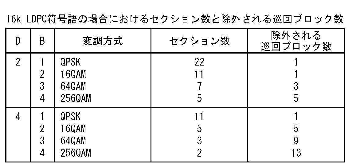

(2)実施の形態の説明で用いたQ、N、M、Bなどのパラメータの値は一例であって、他の値であってもよい。
(3)実施の形態では、PAMマッパ130によって作られる全PAMシンボルの変調多値数は同じである(全PAMシンボルはBビットから作られる)として説明した。
しかしながら、全PAMシンボルの変調多値数は互いに同じであってもよいし、全PAMシンボルの一部だけ変調多値数が同じであってもよい(変調多値数が異なるPAMシンボルが作られてもよい。
具体例を記載する。
2次元ベクトル(2次元コンステレーションブロック)の場合、2つのPAMシンボルがともに4-PAMシンボル(B=2)である。あるいは、一方のPAMシンボルが2-PAMシンボル(B=1)で他方のPAMシンボルが4-PAMシンボル(B=2)である。
なお、D次元ベクトルのD個の全次元のPAMシンボルがBビットから作られている場合、上述したように、例えばMはB×Dである。
また、D次元ベクトルの次元i(i=1、2、・・・、D)のPAMシンボルがB(i)ビットから作られている場合、例えば、MはB(1)+B(2)+・・・+B(D)である。この場合、(2B(1))×(2B(2))×・・・×(2B(D))個のD次元ベクトルがD次元コンステレーションを形成することになる。
(4)実施の形態は、ハードウェアとソフトウェアを使った実装に関するものであってもよい。上記の実施の形態はコンピューティングデバイス(プロセッサ)を使って実装又は実行されてもよい。コンピューティングデバイスまたはプロセッサは、例えば、メインプロセッサ/汎用プロセッサ(general purpose processor)、デジタル信号プロセッサ(DSP)、ASIC(application specific integrated circuit)、FPGA(field programmable gate array)、他のプロラマブル論理デバイスなどであってよい。上記の実施の形態は、これらのデバイスの結合によって実行され、あるいは、実現されてもよい。
(5)実施の形態は、プロセッサによって、または、直接ハードウェアによって実行される、ソフトウェアモジュールの仕組みによって実現されてもよい。また、ソフトウェアモジュールとハードウェア実装の組み合わせも可能である。ソフトウェアモジュールは、様々な種類のコンピュータ読み取り可能なストレージメディア、例えば、RAM、EPROM、EEPROM、フラッシュメモリ、レジスタ、ハードディスク、CD-ROM、DVDなど、に保存されてもよい。
≪補足(その2)≫
実施の形態等に係る送信方法、送信機、受信方法、および受信機とその効果についてまとめる。
実施の形態等に係る送信方法、送信機、受信方法、および受信機とその効果についてまとめる。
(1)第1の送信方法は、
NRF(2以上の整数)個の周波数チャネル及びNC(1以上の整数)個のサイクルを用いて1つの符号ブロックを複数のスライスに分けて送信する送信方法であって、
疑似巡回低密度パリティ検査符号を用いてデータブロックを前記符号ブロックに符号化し、当該符号化ブロックはN個の巡回ブロックからなり、当該N個の巡回ブロックの夫々はQビットからなり、前記N個の巡回ブロックは、夫々がM個の巡回ブロックからなるfloor(N/M)個のセクションとrem{N,M}個の巡回ブロックとに分かられ、
各前記セクションにおいて、当該セクションのQ×M個のビットから夫々が実数値であるD個のコンポーネントからなるD次元コンステレーションブロックを生成し、
各前記セクションのD次元コンステレーションブロックの夫々から、D行D列の直交行列を用いて夫々が実数値であるD個の回転コンポーネントからなるD次元回転コンステレーションブロックを生成し、
各前記セクションの夫々の各前記D次元回転コンステレーションブロックの各前記回転コンポーネントを前記NRF個の周波数チャネルの1つの周波数チャネルにマッピングする、
送信方法であり、
各前記回転コンポーネントの前記周波数チャネルへのマッピングは、
各前記セクションにおいて、D×Q個の前記回転コンポーネントをD行Q列の実数インターリーバ行列に列方向に書き込み、各前記D行Q列の実数インターリーバ行列を同じ行の連続する2列の回転コンポーネントを1つの複素値であるセルに置き換えたD行(Q/2)列の複素インターリーバ行列に変換し、
各前記セクションの前記D行(Q/2)列の複素インターリーバ行列を並べることによって、{floor(N/M)}×D行(Q/2)列の結合複素インターリーバ行列に結合し、
前記結合複素インターリーバ行列の各行に対して、当該行に割り当てられた巡回シフト値k×floor(Q/max{D,(NRF×NC)}/2)セルを用いた巡回シフトを適用し、
巡回シフト後の前記結合複素値インターリーバ行列の連続するQ/2とNRF×NCとで定まる列数分のセルを前記NRF個の周波数チャネルを順番に繰り返しながら前記周波数チャネルにマッピングする、
ことと等価な処理を実行することによって行われ、
前記巡回シフトは、各前記セクションでは、0以上max{D,(NRF×NC)}-1以下の値から予め定められた2以上のkの値が少なくとも1回を用いるように行われる。
これによれば、D次元回転コンステレーションブロックのD個の回転コンポーネントを2以上の周波数チャネルで送信することができ、受信性能の向上が図られる。
(2)第2の送信方法は、第1の送信方法において、
前記Dが2の場合、前記結合複素インターリーバ行列の1つのセクション部分では一方の行のkの値をk mod NRF=0を満たす値、他方の行のkの値をk mod NRF≠0を満たす値とする。
前記Dが2の場合、前記結合複素インターリーバ行列の1つのセクション部分では一方の行のkの値をk mod NRF=0を満たす値、他方の行のkの値をk mod NRF≠0を満たす値とする。
これによれば、2次元回転コンステレーションブロックの2個の回転コンポーネントが互いに異なる周波数チャネルで送信することができ、更なる受信性能の向上が図られる。
(3)第3の送信方法は、第1の送信方法において、
前記Dが4の場合であって、DがNRF以下の場合、前記結合複素インターリーバ行列の1つのセクション部分では、kの値がk mod NRF=0を満たす値、k mod NRF=Lを満たす値、kの値がk mod NRF=Mを満たす値、及びk mod NRF=Nを満たす値、の行が夫々1つ存在し、L、M、Nは互いに異なる1以上の整数である。
前記Dが4の場合であって、DがNRF以下の場合、前記結合複素インターリーバ行列の1つのセクション部分では、kの値がk mod NRF=0を満たす値、k mod NRF=Lを満たす値、kの値がk mod NRF=Mを満たす値、及びk mod NRF=Nを満たす値、の行が夫々1つ存在し、L、M、Nは互いに異なる1以上の整数である。
これによれば、4次元回転コンステレーションブロックの4個の回転コンポーネントが互いに異なる周波数チャネルで送信することができ、更なる受信性能の向上が図られる。
(4)第1の受信方法は、
NRF(2以上の整数)個の周波数チャネル及びNC(1以上の整数)個のサイクルを用いて1つの符号ブロックを複数のスライスに分けて受信する受信方法であって、
前記NRF(2以上の整数)個の周波数チャネルから、時間-周波数スライシングスケジュール情報に従って複数のセルを受信し、
請求項1の実数値回転コンポーネントの周波数チャネルへのマッピングの規則に基づいて、前記複数のセルの実数コンポーネント及び虚数コンポーネントを、複数のD次元回転コンステレーションブロックのD個の実数値回転コンポーネントにマッピングし、
前記複数のD次元回転コンステレーションブロックを疑似巡回低密度パリティ検査符号を用いてデコードする。
これによれば、D次元回転コンステレーションブロックのD個の回転コンポーネントを2以上の周波数チャネルで受信することができ、受信性能の向上が図られる。
(5)第1の送信機は、
NRF(2以上の整数)個の周波数チャネル及びNC(1以上の整数)個のサイクルを用いて1つの符号ブロックを複数のスライスに分けて送信する送信機であって、
疑似巡回低密度パリティ検査符号を用いてデータブロックを前記符号ブロックに符号化し、当該符号化ブロックはN個の巡回ブロックからなり、当該N個の巡回ブロックの夫々はQビットからなり、前記N個の巡回ブロックは、夫々がM個の巡回ブロックからなるfloor(N/M)個のセクションとrem{N,M}個の巡回ブロックとに分かられ、
各前記セクションにおいて、当該セクションのQ×M個のビットから夫々が実数値であるD個のコンポーネントからなるD次元コンステレーションブロックを生成し、
各前記セクションのD次元コンステレーションブロックの夫々から、D行D列の直交行列を用いて夫々が実数値であるD個の回転コンポーネントからなるD次元回転コンステレーションブロックを生成し、
各前記セクションの夫々の各前記D次元回転コンステレーションブロックの各前記回転コンポーネントを前記NRF個の周波数チャネルの1つの周波数チャネルにマッピングする、
送信機であり、
各前記回転コンポーネントの前記周波数チャネルへのマッピングは、
各前記セクションにおいて、D×Q個の前記回転コンポーネントをD行Q列の実数インターリーバ行列に列方向に書き込み、各前記D行Q列の実数インターリーバ行列を同じ行の連続する2列の回転コンポーネントを1つの複素値であるセルに置き換えたD行(Q/2)列の複素インターリーバ行列に変換し、
各前記セクションの前記D行(Q/2)列の複素インターリーバ行列を並べることによって、{floor(N/M)}×D行(Q/2)列の結合複素インターリーバ行列に結合し、
前記結合複素インターリーバ行列の各行に対して、当該行に割り当てられた巡回シフト値k×floor(Q/max{D,(NRF×NC)}/2)セルを用いた巡回シフトを適用し、
巡回シフト後の前記結合複素値インターリーバ行列の連続するQ/2とNRF×NCとで定まる列数分のセルを前記NRF個の周波数チャネルを順番に繰り返しながら前記周波数チャネルにマッピングする、
ことと等価な処理を実行することによって行われ、
前記巡回シフトは、各前記セクションでは、0以上max{D,(NRF×NC)}-1以下の値から予め定められた2以上のkの値が少なくとも1回を用いるように行われる。
これによれば、D次元回転コンステレーションブロックのD個の回転コンポーネントを2以上の周波数チャネルで送信することができ、受信性能の向上が図られる。
(6)第1の受信機は、
NRF(2以上の整数)個の周波数チャネル及びNC(1以上の整数)個のサイクルを用いて1つの符号ブロックを複数のスライスに分けて受信する受信機であって、
前記NRF(2以上の整数)個の周波数チャネルから、時間-周波数スライシングスケジュール情報に従って複数のセルを受信し、
請求項1の実数値回転コンポーネントの周波数チャネルへのマッピングの規則に基づいて、前記複数のセルの実数コンポーネント及び虚数コンポーネントを、複数のD次元回転コンステレーションブロックのD個の実数値回転コンポーネントにマッピングし、
前記複数のD次元回転コンステレーションブロックを疑似巡回低密度パリティ検査符号を用いてデコードする。
これによれば、D次元回転コンステレーションブロックのD個の回転コンポーネントを2以上の周波数チャネルで受信することができ、受信性能の向上が図られる。
本開示は、疑似巡回低密度パリティ検査符号とともに回転コンステレーション及び複数の周波数チャネルを用いる通信システムに利用することができる。
100,100A 送信機
110 LDPCエンコーダ
120,120A ビットインターリーバ
130 PAMマッパ
140,140A コンポーネントデインターリーバ
150 コンステレーションローテータ
160,160A コンポーネントインターリーバ
170 セルインターリーバ
180 スケジューラ
190-1~190-n 変調器
200-1~200-n 送信アンテナ
500,500A,500B,500C 受信機
510 受信アンテナ
520 RFフロントエンド
530,530A,630 コンポーネントデインターリーバ
540 回転コンステレーションデマッパ
550 コンポーネントインターリーバ
560 ビットデインターリーバ
570 LDPCデコーダ
Claims (6)
- NRF(2以上の整数)個の周波数チャネル及びNC(1以上の整数)個のサイクルを用いて1つの符号ブロックを複数のスライスに分けて送信する送信方法であって、
疑似巡回低密度パリティ検査符号を用いてデータブロックを前記符号ブロックに符号化し、当該符号化ブロックはN個の巡回ブロックからなり、当該N個の巡回ブロックの夫々はQビットからなり、前記N個の巡回ブロックは、夫々がM個の巡回ブロックからなるfloor(N/M)個のセクションとrem{N,M}個の巡回ブロックとに分かられ、
各前記セクションにおいて、当該セクションのQ×M個のビットから夫々が実数値であるD個のコンポーネントからなるD次元コンステレーションブロックを生成し、
各前記セクションのD次元コンステレーションブロックの夫々から、D行D列の直交行列を用いて夫々が実数値であるD個の回転コンポーネントからなるD次元回転コンステレーションブロックを生成し、
各前記セクションの夫々の各前記D次元回転コンステレーションブロックの各前記回転コンポーネントを前記NRF個の周波数チャネルの1つの周波数チャネルにマッピングする、
送信方法であり、
各前記回転コンポーネントの前記周波数チャネルへのマッピングは、
各前記セクションにおいて、D×Q個の前記回転コンポーネントをD行Q列の実数インターリーバ行列に列方向に書き込み、各前記D行Q列の実数インターリーバ行列を同じ行の連続する2列の回転コンポーネントを1つの複素値であるセルに置き換えたD行(Q/2)列の複素インターリーバ行列に変換し、
各前記セクションの前記D行(Q/2)列の複素インターリーバ行列を並べることによって、{floor(N/M)}×D行(Q/2)列の結合複素インターリーバ行列に結合し、
前記結合複素インターリーバ行列の各行に対して、当該行に割り当てられた巡回シフト値k×floor(Q/max{D,(NRF×NC)}/2)セルを用いた巡回シフトを適用し、
巡回シフト後の前記結合複素値インターリーバ行列の連続するQ/2とNRF×NCとで定まる列数分のセルを前記NRF個の周波数チャネルを順番に繰り返しながら前記周波数チャネルにマッピングする、
ことと等価な処理を実行することによって行われ、
前記巡回シフトは、各前記セクションでは、0以上max{D,(NRF×NC)}-1以下の値から予め定められた2以上のkの値が少なくとも1回を用いるように行われる、
送信方法。 - 前記Dが2の場合、前記結合複素インターリーバ行列の1つのセクション部分では一方の行のkの値をk mod NRF=0を満たす値、他方の行のkの値をk mod NRF≠0を満たす値とする、
ことを特徴とする請求項1記載の送信方法。 - 前記Dが4の場合であって、DがNRF以下の場合、前記結合複素インターリーバ行列の1つのセクション部分では、kの値がk mod NRF=0を満たす値、k mod NRF=Lを満たす値、kの値がk mod NRF=Mを満たす値、及びk mod NRF=Nを満たす値、の行が夫々1つ存在し、L、M、Nは互いに異なる1以上の整数である、
ことを特徴とする請求項1記載の送信方法。 - NRF(2以上の整数)個の周波数チャネル及びNC(1以上の整数)個のサイクルを用いて1つの符号ブロックを複数のスライスに分けて受信する受信方法であって、
前記NRF(2以上の整数)個の周波数チャネルから、時間-周波数スライシングスケジュール情報に従って複数のセルを受信し、
請求項1の実数値回転コンポーネントの周波数チャネルへのマッピングの規則に基づいて、前記複数のセルの実数コンポーネント及び虚数コンポーネントを、複数のD次元回転コンステレーションブロックのD個の実数値回転コンポーネントにマッピングし、
前記複数のD次元回転コンステレーションブロックを疑似巡回低密度パリティ検査符号を用いてデコードする、
受信方法。 - NRF(2以上の整数)個の周波数チャネル及びNC(1以上の整数)個のサイクルを用いて1つの符号ブロックを複数のスライスに分けて送信する送信機であって、
疑似巡回低密度パリティ検査符号を用いてデータブロックを前記符号ブロックに符号化し、当該符号化ブロックはN個の巡回ブロックからなり、当該N個の巡回ブロックの夫々はQビットからなり、前記N個の巡回ブロックは、夫々がM個の巡回ブロックからなるfloor(N/M)個のセクションとrem{N,M}個の巡回ブロックとに分かられ、
各前記セクションにおいて、当該セクションのQ×M個のビットから夫々が実数値であるD個のコンポーネントからなるD次元コンステレーションブロックを生成し、
各前記セクションのD次元コンステレーションブロックの夫々から、D行D列の直交行列を用いて夫々が実数値であるD個の回転コンポーネントからなるD次元回転コンステレーションブロックを生成し、
各前記セクションの夫々の各前記D次元回転コンステレーションブロックの各前記回転コンポーネントを前記NRF個の周波数チャネルの1つの周波数チャネルにマッピングする、
送信機であり、
各前記回転コンポーネントの前記周波数チャネルへのマッピングは、
各前記セクションにおいて、D×Q個の前記回転コンポーネントをD行Q列の実数インターリーバ行列に列方向に書き込み、各前記D行Q列の実数インターリーバ行列を同じ行の連続する2列の回転コンポーネントを1つの複素値であるセルに置き換えたD行(Q/2)列の複素インターリーバ行列に変換し、
各前記セクションの前記D行(Q/2)列の複素インターリーバ行列を並べることによって、{floor(N/M)}×D行(Q/2)列の結合複素インターリーバ行列に結合し、
前記結合複素インターリーバ行列の各行に対して、当該行に割り当てられた巡回シフト値k×floor(Q/max{D,(NRF×NC)}/2)セルを用いた巡回シフトを適用し、
巡回シフト後の前記結合複素値インターリーバ行列の連続するQ/2とNRF×NCとで定まる列数分のセルを前記NRF個の周波数チャネルを順番に繰り返しながら前記周波数チャネルにマッピングする、
ことと等価な処理を実行することによって行われ、
前記巡回シフトは、各前記セクションでは、0以上max{D,(NRF×NC)}-1以下の値から予め定められた2以上のkの値が少なくとも1回を用いるように行われる、
送信機。 - NRF(2以上の整数)個の周波数チャネル及びNC(1以上の整数)個のサイクルを用いて1つの符号ブロックを複数のスライスに分けて受信する受信機であって、
前記NRF(2以上の整数)個の周波数チャネルから、時間-周波数スライシングスケジュール情報に従って複数のセルを受信し、
請求項1の実数値回転コンポーネントの周波数チャネルへのマッピングの規則に基づいて、前記複数のセルの実数コンポーネント及び虚数コンポーネントを、複数のD次元回転コンステレーションブロックのD個の実数値回転コンポーネントにマッピングし、
前記複数のD次元回転コンステレーションブロックを疑似巡回低密度パリティ検査符号を用いてデコードする、
受信機。
Priority Applications (2)
| Application Number | Priority Date | Filing Date | Title |
|---|---|---|---|
| EP14866685.2A EP3076556B1 (en) | 2013-11-29 | 2014-11-21 | Transmission method, transmission device, receiving method, and receiving device |
| US15/158,641 US10142056B2 (en) | 2013-11-29 | 2016-05-19 | Transmission method, transmitter, reception method, and receiver |
Applications Claiming Priority (4)
| Application Number | Priority Date | Filing Date | Title |
|---|---|---|---|
| EP13195168.3A EP2879318A1 (en) | 2013-11-29 | 2013-11-29 | Efficient component interleaving for rotated constellations with time-frequency slicing |
| EP13195168.3 | 2013-11-29 | ||
| JP2014-226255 | 2014-11-06 | ||
| JP2014226255A JP6271397B2 (ja) | 2013-11-29 | 2014-11-06 | 送信方法、送信機、受信方法、及び受信機 |
Related Child Applications (1)
| Application Number | Title | Priority Date | Filing Date |
|---|---|---|---|
| US15/158,641 Continuation US10142056B2 (en) | 2013-11-29 | 2016-05-19 | Transmission method, transmitter, reception method, and receiver |
Publications (1)
| Publication Number | Publication Date |
|---|---|
| WO2015079665A1 true WO2015079665A1 (ja) | 2015-06-04 |
Family
ID=53198633
Family Applications (1)
| Application Number | Title | Priority Date | Filing Date |
|---|---|---|---|
| PCT/JP2014/005854 WO2015079665A1 (ja) | 2013-11-29 | 2014-11-21 | 送信方法、送信機、受信方法、及び受信機 |
Country Status (1)
| Country | Link |
|---|---|
| WO (1) | WO2015079665A1 (ja) |
Cited By (1)
| Publication number | Priority date | Publication date | Assignee | Title |
|---|---|---|---|---|
| CN115952385A (zh) * | 2023-03-10 | 2023-04-11 | 山东省计算中心(国家超级计算济南中心) | 用于大规模稀疏方程组求解的并行超节点排序方法及系统 |
Citations (7)
| Publication number | Priority date | Publication date | Assignee | Title |
|---|---|---|---|---|
| EP2288048A1 (en) | 2009-08-21 | 2011-02-23 | Panasonic Corporation | Rotated multi-dimensional constellations for improved diversity in fading channels |
| EP2525497A1 (en) | 2011-05-18 | 2012-11-21 | Panasonic Corporation | Bit-interleaved coding and modulation (BICM) with quasi-cyclic LDPC codes |
| WO2013010861A1 (de) * | 2011-07-21 | 2013-01-24 | Siemens Aktiengesellschaft | Verfahren zur standzeitbeurteilung von wolframelektroden |
| EP2618532A1 (en) | 2012-01-19 | 2013-07-24 | Panasonic Corporation | Improved Component Interleaving for Rotated Constellations |
| EP2690813A1 (en) | 2012-07-27 | 2014-01-29 | Panasonic Corporation | Transparent component interleaving for rotated constellations |
| EP2690791A1 (en) | 2012-07-27 | 2014-01-29 | Panasonic Corporation | Component interleaving for rotated constellations with quasi-cylic LDPC codes |
| WO2014017102A1 (ja) * | 2012-07-27 | 2014-01-30 | パナソニック株式会社 | 送信方法、受信方法、送信機、及び受信機 |
-
2014
- 2014-11-21 WO PCT/JP2014/005854 patent/WO2015079665A1/ja active Application Filing
Patent Citations (7)
| Publication number | Priority date | Publication date | Assignee | Title |
|---|---|---|---|---|
| EP2288048A1 (en) | 2009-08-21 | 2011-02-23 | Panasonic Corporation | Rotated multi-dimensional constellations for improved diversity in fading channels |
| EP2525497A1 (en) | 2011-05-18 | 2012-11-21 | Panasonic Corporation | Bit-interleaved coding and modulation (BICM) with quasi-cyclic LDPC codes |
| WO2013010861A1 (de) * | 2011-07-21 | 2013-01-24 | Siemens Aktiengesellschaft | Verfahren zur standzeitbeurteilung von wolframelektroden |
| EP2618532A1 (en) | 2012-01-19 | 2013-07-24 | Panasonic Corporation | Improved Component Interleaving for Rotated Constellations |
| EP2690813A1 (en) | 2012-07-27 | 2014-01-29 | Panasonic Corporation | Transparent component interleaving for rotated constellations |
| EP2690791A1 (en) | 2012-07-27 | 2014-01-29 | Panasonic Corporation | Component interleaving for rotated constellations with quasi-cylic LDPC codes |
| WO2014017102A1 (ja) * | 2012-07-27 | 2014-01-30 | パナソニック株式会社 | 送信方法、受信方法、送信機、及び受信機 |
Non-Patent Citations (2)
| Title |
|---|
| ETSI EN 302 755 V1. 3.1, April 2012 (2012-04-01), pages 1,19 - 21 , 50 - 52 , 159-161, XP055257698 * |
| MARIEM MAKNI ET AL.: "Performance analysis of time frequency slicing", ELECTRONIC MEDIA TECHNOLOGY (CEMT), 2011 14TH ITG CONFERENCE ON, 23 March 2011 (2011-03-23), pages 1 - 6, XP055289147 * |
Cited By (2)
| Publication number | Priority date | Publication date | Assignee | Title |
|---|---|---|---|---|
| CN115952385A (zh) * | 2023-03-10 | 2023-04-11 | 山东省计算中心(国家超级计算济南中心) | 用于大规模稀疏方程组求解的并行超节点排序方法及系统 |
| CN115952385B (zh) * | 2023-03-10 | 2023-05-05 | 山东省计算中心(国家超级计算济南中心) | 用于大规模稀疏方程组求解的并行超节点排序方法及系统 |
Similar Documents
| Publication | Publication Date | Title |
|---|---|---|
| JP6975303B2 (ja) | 並列ビットインターリーバ | |
| JP6271397B2 (ja) | 送信方法、送信機、受信方法、及び受信機 | |
| JP7011014B2 (ja) | 並列ビットインターリーバ | |
| JP7011013B2 (ja) | 並列ビットインターリーバ | |
| JP6999010B2 (ja) | 並列ビットインターリーバ | |
| JP6252924B2 (ja) | 送信方法、送信機、受信方法、及び受信機 | |
| WO2014017102A1 (ja) | 送信方法、受信方法、送信機、及び受信機 | |
| KR102606204B1 (ko) | 송신 장치 및 그의 신호 처리 방법 | |
| EP2690791A1 (en) | Component interleaving for rotated constellations with quasi-cylic LDPC codes | |
| WO2015079665A1 (ja) | 送信方法、送信機、受信方法、及び受信機 | |
| KR20150040243A (ko) | 송신 장치 및 그의 신호 처리 방법 | |
| KR102163710B1 (ko) | 송신 장치 및 그의 신호 처리 방법 | |
| KR20200117940A (ko) | 송신 장치 및 그의 신호 처리 방법 |
Legal Events
| Date | Code | Title | Description |
|---|---|---|---|
| 121 | Ep: the epo has been informed by wipo that ep was designated in this application |
Ref document number: 14866685 Country of ref document: EP Kind code of ref document: A1 |
|
| REEP | Request for entry into the european phase |
Ref document number: 2014866685 Country of ref document: EP |
|
| WWE | Wipo information: entry into national phase |
Ref document number: 2014866685 Country of ref document: EP |
|
| NENP | Non-entry into the national phase |
Ref country code: DE |