WO2015079607A1 - 電池パック - Google Patents
電池パック Download PDFInfo
- Publication number
- WO2015079607A1 WO2015079607A1 PCT/JP2014/004592 JP2014004592W WO2015079607A1 WO 2015079607 A1 WO2015079607 A1 WO 2015079607A1 JP 2014004592 W JP2014004592 W JP 2014004592W WO 2015079607 A1 WO2015079607 A1 WO 2015079607A1
- Authority
- WO
- WIPO (PCT)
- Prior art keywords
- voltage
- capacity
- secondary battery
- mode
- charge
- Prior art date
- Legal status (The legal status is an assumption and is not a legal conclusion. Google has not performed a legal analysis and makes no representation as to the accuracy of the status listed.)
- Ceased
Links
Images



Classifications
-
- H—ELECTRICITY
- H01—ELECTRIC ELEMENTS
- H01M—PROCESSES OR MEANS, e.g. BATTERIES, FOR THE DIRECT CONVERSION OF CHEMICAL ENERGY INTO ELECTRICAL ENERGY
- H01M10/00—Secondary cells; Manufacture thereof
- H01M10/42—Methods or arrangements for servicing or maintenance of secondary cells or secondary half-cells
- H01M10/48—Accumulators combined with arrangements for measuring, testing or indicating the condition of cells, e.g. the level or density of the electrolyte
-
- H—ELECTRICITY
- H01—ELECTRIC ELEMENTS
- H01M—PROCESSES OR MEANS, e.g. BATTERIES, FOR THE DIRECT CONVERSION OF CHEMICAL ENERGY INTO ELECTRICAL ENERGY
- H01M10/00—Secondary cells; Manufacture thereof
- H01M10/42—Methods or arrangements for servicing or maintenance of secondary cells or secondary half-cells
- H01M10/46—Accumulators structurally combined with charging apparatus
-
- H—ELECTRICITY
- H02—GENERATION; CONVERSION OR DISTRIBUTION OF ELECTRIC POWER
- H02J—ELECTRIC POWER NETWORKS; CIRCUIT ARRANGEMENTS OR SYSTEMS FOR SUPPLYING OR DISTRIBUTING ELECTRIC POWER; SYSTEMS FOR STORING ELECTRIC ENERGY
- H02J7/00—Circuit arrangements for charging or discharging batteries or for supplying loads from batteries
- H02J7/80—Circuit arrangements for charging or discharging batteries or for supplying loads from batteries including monitoring or indicating arrangements
- H02J7/82—Control of state of charge [SOC]
- H02J7/825—Detection of fully charged condition
-
- H—ELECTRICITY
- H02—GENERATION; CONVERSION OR DISTRIBUTION OF ELECTRIC POWER
- H02J—ELECTRIC POWER NETWORKS; CIRCUIT ARRANGEMENTS OR SYSTEMS FOR SUPPLYING OR DISTRIBUTING ELECTRIC POWER; SYSTEMS FOR STORING ELECTRIC ENERGY
- H02J7/00—Circuit arrangements for charging or discharging batteries or for supplying loads from batteries
- H02J7/865—Battery or charger load switching, e.g. concurrent charging and load supply
-
- G—PHYSICS
- G01—MEASURING; TESTING
- G01R—MEASURING ELECTRIC VARIABLES; MEASURING MAGNETIC VARIABLES
- G01R31/00—Arrangements for testing electric properties; Arrangements for locating electric faults; Arrangements for electrical testing characterised by what is being tested not provided for elsewhere
- G01R31/36—Arrangements for testing, measuring or monitoring the electrical condition of accumulators or electric batteries, e.g. capacity or state of charge [SoC]
- G01R31/392—Determining battery ageing or deterioration, e.g. state of health
-
- H—ELECTRICITY
- H01—ELECTRIC ELEMENTS
- H01M—PROCESSES OR MEANS, e.g. BATTERIES, FOR THE DIRECT CONVERSION OF CHEMICAL ENERGY INTO ELECTRICAL ENERGY
- H01M10/00—Secondary cells; Manufacture thereof
- H01M10/05—Accumulators with non-aqueous electrolyte
- H01M10/052—Li-accumulators
- H01M10/0525—Rocking-chair batteries, i.e. batteries with lithium insertion or intercalation in both electrodes; Lithium-ion batteries
-
- H—ELECTRICITY
- H01—ELECTRIC ELEMENTS
- H01M—PROCESSES OR MEANS, e.g. BATTERIES, FOR THE DIRECT CONVERSION OF CHEMICAL ENERGY INTO ELECTRICAL ENERGY
- H01M10/00—Secondary cells; Manufacture thereof
- H01M10/42—Methods or arrangements for servicing or maintenance of secondary cells or secondary half-cells
- H01M10/44—Methods for charging or discharging
-
- H—ELECTRICITY
- H01—ELECTRIC ELEMENTS
- H01M—PROCESSES OR MEANS, e.g. BATTERIES, FOR THE DIRECT CONVERSION OF CHEMICAL ENERGY INTO ELECTRICAL ENERGY
- H01M2220/00—Batteries for particular applications
- H01M2220/30—Batteries in portable systems, e.g. mobile phone, laptop
-
- H—ELECTRICITY
- H02—GENERATION; CONVERSION OR DISTRIBUTION OF ELECTRIC POWER
- H02J—ELECTRIC POWER NETWORKS; CIRCUIT ARRANGEMENTS OR SYSTEMS FOR SUPPLYING OR DISTRIBUTING ELECTRIC POWER; SYSTEMS FOR STORING ELECTRIC ENERGY
- H02J7/00—Circuit arrangements for charging or discharging batteries or for supplying loads from batteries
- H02J7/02—Circuit arrangements for charging or discharging batteries or for supplying loads from batteries for charging batteries from AC mains by converters
- H02J7/04—Regulation of charging current or voltage
-
- H—ELECTRICITY
- H02—GENERATION; CONVERSION OR DISTRIBUTION OF ELECTRIC POWER
- H02J—ELECTRIC POWER NETWORKS; CIRCUIT ARRANGEMENTS OR SYSTEMS FOR SUPPLYING OR DISTRIBUTING ELECTRIC POWER; SYSTEMS FOR STORING ELECTRIC ENERGY
- H02J7/00—Circuit arrangements for charging or discharging batteries or for supplying loads from batteries
- H02J7/80—Circuit arrangements for charging or discharging batteries or for supplying loads from batteries including monitoring or indicating arrangements
- H02J7/82—Control of state of charge [SOC]
-
- H—ELECTRICITY
- H02—GENERATION; CONVERSION OR DISTRIBUTION OF ELECTRIC POWER
- H02J—ELECTRIC POWER NETWORKS; CIRCUIT ARRANGEMENTS OR SYSTEMS FOR SUPPLYING OR DISTRIBUTING ELECTRIC POWER; SYSTEMS FOR STORING ELECTRIC ENERGY
- H02J7/00—Circuit arrangements for charging or discharging batteries or for supplying loads from batteries
- H02J7/90—Regulation of charging or discharging current or voltage
- H02J7/94—Regulation of charging or discharging current or voltage in response to battery current
-
- H—ELECTRICITY
- H02—GENERATION; CONVERSION OR DISTRIBUTION OF ELECTRIC POWER
- H02J—ELECTRIC POWER NETWORKS; CIRCUIT ARRANGEMENTS OR SYSTEMS FOR SUPPLYING OR DISTRIBUTING ELECTRIC POWER; SYSTEMS FOR STORING ELECTRIC ENERGY
- H02J7/00—Circuit arrangements for charging or discharging batteries or for supplying loads from batteries
- H02J7/90—Regulation of charging or discharging current or voltage
- H02J7/96—Regulation of charging or discharging current or voltage in response to battery voltage
-
- Y—GENERAL TAGGING OF NEW TECHNOLOGICAL DEVELOPMENTS; GENERAL TAGGING OF CROSS-SECTIONAL TECHNOLOGIES SPANNING OVER SEVERAL SECTIONS OF THE IPC; TECHNICAL SUBJECTS COVERED BY FORMER USPC CROSS-REFERENCE ART COLLECTIONS [XRACs] AND DIGESTS
- Y02—TECHNOLOGIES OR APPLICATIONS FOR MITIGATION OR ADAPTATION AGAINST CLIMATE CHANGE
- Y02E—REDUCTION OF GREENHOUSE GAS [GHG] EMISSIONS, RELATED TO ENERGY GENERATION, TRANSMISSION OR DISTRIBUTION
- Y02E60/00—Enabling technologies; Technologies with a potential or indirect contribution to GHG emissions mitigation
- Y02E60/10—Energy storage using batteries
Definitions
- the present invention changes the end-of-charge voltage when charging the secondary battery to a high capacity mode in which the charge capacity is increased until the secondary battery is fully charged, or a long life mode in which the cycle life of the secondary battery is extended.
- a battery pack including a secondary battery and a control calculation unit that controls charge / discharge of the secondary battery is widely used as a power supply unit that is mounted on an electronic device such as a notebook personal computer (PC).
- the secondary battery in the battery pack used for these electronic devices is charged by an external power source (commercial power source) via, for example, the power source of the electronic device, and when the electronic device is removed from the external power source, it replaces the external power source. Plays a role in supplying power to electronic devices.
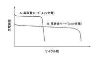
- the characteristics of a secondary battery for example, a lithium ion battery, specifically, the charge capacity and the cycle life greatly vary depending on the charge voltage as shown in FIG. Specifically, when a secondary battery (lithium ion battery) is charged by increasing the charge end voltage, which is a voltage for detecting the end of charge, the charge capacity can be increased as shown by the characteristic A in FIG. However, the cycle life is short. On the other hand, when the secondary battery (lithium ion battery) is charged with a lower end-of-charge voltage, the charge capacity is reduced as shown in FIG.
- the battery pack in the high capacity mode or the long life mode by switching the charge end voltage at the time of charging the secondary battery (for example, (See Patent Document 1). Specifically, in the high capacity mode, the end-of-charge voltage for the secondary battery (lithium ion battery) is set to 4.2 V / cell, and in the long life mode, the secondary battery (lithium ion battery) is set. ) Is set to 4.0 V / cell, and charging is performed.
- the ratio of the remaining capacity (RC) is obtained by setting the fully charged state (full charge capacity; FCC) of the secondary battery as 100%, and the relative remaining capacity (RSOC). It is often managed as.
- the standard capacity (DC) or full charge capacity (FCC) of the secondary battery is set. 100% is the maximum charge capacity, and when the long life mode is set, the ratio of the secondary battery standard capacity (DC) or full charge capacity (FCC) is 100% or less, for example, 80% is the maximum charge capacity. used. Therefore, as shown in FIG. 8, the charge end voltage in the high capacity mode is set to 4.2 V / cell, and the charge end voltage in the long life mode is set to 4.0 V / cell.
- the present invention has been made in consideration of such circumstances, and the purpose thereof is to suppress deterioration due to overcharge of a secondary battery used by being selectively set to a high capacity mode or a long life mode.
- An object of the present invention is to provide a battery pack capable of accurately obtaining the relative remaining capacity of a battery according to the operation mode (charging mode) and even when the operation mode is changed.
- a battery pack includes a secondary battery and a control calculation unit that controls charging and discharging of the secondary battery, and the control calculation unit terminates charging of the secondary battery.
- a high capacity mode in which the voltage is limited to the first voltage to increase the full charge capacity of the secondary battery, or the charge end voltage is limited to a second voltage lower than the first voltage and the secondary battery
- An operation mode setting unit for selectively setting a long life mode for extending the cycle life of the battery, and determining the discharge capacity of the secondary battery based on the discharge current and discharge time or discharge current and battery voltage of the secondary battery,
- a remaining capacity calculation unit that calculates a relative remaining capacity of the secondary battery from a discharge capacity and a full charge capacity of the secondary battery, and a cycle number of the secondary battery is calculated from a calculation result of the remaining capacity calculation unit.
- a cycle number calculating unit The first voltage is reduced based on a number, and when the first voltage is equal to or less than a value obtained by adding a predetermined voltage to the second voltage, the second voltage is reduced from the first voltage.
- an end-of-charge voltage setting unit for subtracting a predetermined voltage.
- the relative remaining capacity of the secondary battery is set to the operation mode while suppressing deterioration due to overcharge of the secondary battery that is selected and set to the high capacity mode or the long life mode. Accordingly, it is possible to provide a battery pack that can be accurately obtained even when the operation mode is changed.
- FIG. 1 is a configuration diagram of a battery pack according to an embodiment of the present invention.
- the battery pack 10 is detachably attached to an electronic device 20 such as a notebook personal computer (PC).
- the battery pack 10 basically includes a secondary battery (BAT) 11 and a control unit 12 that controls charging / discharging of the secondary battery 11, and is used by being mounted on the electronic device 20.
- BAT secondary battery
- control unit 12 that controls charging / discharging of the secondary battery 11 and is used by being mounted on the electronic device 20.
- the secondary battery 11 in the battery pack 10 includes a plurality of battery cells made of lithium ion batteries of about 2600 mAh / cell, for example, connected in parallel, and these battery cells connected in parallel are arranged in three stages. It consists of a so-called three-line, two-line type connected in series.
- a description will be given by taking a three-series, two-parallel type secondary battery 11 as an example, but the number of battery cells connected in parallel and the number of stages connected in series are determined according to the rated output voltage and the rated output current capacity given as battery specifications. It is good.
- a switching element 13 such as an FET for controlling the charging / discharging is interposed in series, and a shunt resistor is provided as a current detecting unit 14 for detecting the charging / discharging current. It is inserted in series.
- the control unit 12 provided in the battery pack 10 is composed of, for example, a microprocessor (MPU).
- the control / calculation unit 15 constituting the main unit and the terminal voltage of the secondary battery 11, specifically, each stage A voltage detection unit 16 that detects a terminal voltage (cell voltage) of each battery cell and a communication processing unit 17 that performs information communication with the electronic device 20 are provided.
- control / calculation unit 15 uses the temperature (battery temperature) of the secondary battery 11 detected by the temperature detection element 19 such as a thermistor, the cell voltage detected by the voltage detection unit 16, and the current detection unit 14. The charge / discharge state of the secondary battery 11 is monitored based on the detected charge / discharge current.
- the control / arithmetic unit 15 performs on / off control of the switch element 13 to protect the secondary battery 11 from abnormal charging / discharging, and gives a control command to the electronic device 20 side via the communication processing unit 17 to It plays the role of controlling the charging voltage and charging current for the secondary battery 11.
- the electronic device 20 basically receives external power (not shown; commercial power supply) to drive the load 21 which is the main body of the electronic device 20 and supplies power to the battery pack 10.
- the control / power supply unit 22 that charges the secondary battery 11 described above is provided.
- the control / power supply unit 22 plays a role of driving the load 21 with power supplied from the secondary battery 11 of the battery pack 10 when, for example, supply of external power is interrupted.
- the secondary battery 11 is a lithium ion battery
- the secondary battery 11 is charged by the control / power supply unit 22 with a maximum current (about 0.5 to 4 C) and a maximum voltage (about 4.2 V / cell). Is performed by constant current / constant voltage charging that regulates
- the control / power supply unit 22 has a function of performing information communication with the communication processing unit 17 in the battery pack 10 by, for example, the SMBUS method via the data line SDA and the clock line SCL.
- the control unit 12 of the battery pack 10 controls the operation of the control / power supply unit 22 using the information communication function, and variably sets the charging voltage and the charging current of the secondary battery 11 by the control / power supply unit 22.
- the charging of the secondary battery 11 is controlled by the control of the control / power supply unit 22.
- control / arithmetic unit 15 realized by the microprocessor executes a software program registered in the memory 18 in advance, for example, an operation mode setting unit 15a, a charge / discharge control unit 15b, a cycle number calculation unit 15c, and It has a remaining capacity calculator 15d.
- the control / calculation unit 15 is involved in the safe operation of the battery pack 10 such as a full charge detection unit, a failure / abnormality monitoring unit, and a performance (life) determination unit of the secondary battery 11.
- various functions are provided, since they are not directly related to the gist of the present invention, the description thereof is omitted.
- the operation mode setting unit 15a detects the state of a mode change switch (not shown) provided in the battery pack 10 or receives an operation mode selection command notified from the electronic device 20 side to operate the secondary battery 11. For example, the mode is selected and set to a high capacity mode or a long life mode.
- the secondary battery 11 In the high capacity mode, when the secondary battery 11 is a lithium ion battery, the secondary battery 11 is charged by limiting the end-of-charge voltage of the secondary battery 11 to a first voltage (for example, 4.2 V / cell) that becomes a full charge capacity, In this mode, the charging capacity of the secondary battery 11 is sufficiently increased. In the long life mode, the end-of-charge voltage of the secondary battery 11 is limited to a second voltage lower than the first voltage (for example, 4.0 V / cell) to avoid charging near full charge. In this mode, the charging capacity of the secondary battery 11 is suppressed to some extent, and the repeated charge / discharge period, that is, the so-called cycle life is extended.
- the second voltage is suitably 3.9 to 4.1 V / Cell because it does not overcharge and charges a certain amount of capacity.
- the charging of the secondary battery 11 is performed by so-called constant current / constant voltage charging in which the charging current and the charging voltage are limited as described above.
- a constant current / constant voltage power source having a maximum output current of 5000 mA and a maximum output voltage of 4.2 V / cell, for example.
- the first and second voltages described above are voltages that limit the end-of-charge voltage of the secondary battery 11 by the constant current / constant voltage charging, depending on the high capacity mode or the long life mode described above.
- the charge / discharge control unit 15b in the control / calculation unit 15 controls the charging of the secondary battery 11 by restricting the restriction condition according to the above-described operation mode, specifically the charge end voltage, and the maximum discharge current. It plays the role of regulating and controlling the discharge of the secondary battery 11. Further, the cycle number calculation unit 15c monitors the number of cycles of charging of the secondary battery 11 under the above-described charging control, for example, a value obtained by dividing the accumulated discharge amount obtained by accumulating the discharge amount of the secondary battery 11 by the full charge capacity, The number of cycles is calculated by the number of times that the remaining capacity of the secondary battery 11 has become equal to or less than a predetermined capacity close to a discharge disabled state.
- the number of cycles is a value obtained by dividing the accumulated discharge amount by the full charge capacity, but the number of cycles is not limited to this as long as the usage frequency of the secondary battery 11 can be estimated. .
- the remaining capacity calculation unit 15d in the control / calculation unit 15 basically includes an electric energy ( ⁇ W; unit) obtained from the product of the charge / discharge current value and the voltage value of the secondary battery 11 detected by the current detection unit 14. [AV] or [W]), or the amount ( ⁇ I; unit [mAh]) obtained from the charge / discharge current value and the current application time is integrated, and the charge capacity (CC; Charge Capacity) or discharge capacity ( DCC; Discharge Capacity) is calculated. And it plays the role which calculates the ratio of the remaining capacity (RC; Remaining
- the relative remaining capacity is a capacity (FCC ⁇ ) obtained by subtracting the discharge capacity (DCC) from the full charge capacity (FCC) during discharge and using the charge capacity (CC) as the remaining capacity (RC) during discharge.
- DCC is obtained as the remaining capacity (RC), and is calculated by Equation 1.
- the relative remaining capacity (RSOC) of the secondary battery 11 obtained by the remaining capacity calculation unit 15d is notified to the electronic device 20 via the communication processing unit 17 described above.
- the present invention is characterized by the standard capacity (DC: Design ⁇ Capacity) and the full charge capacity (DC) of the secondary battery 11 regardless of the operation mode described above.
- DC Design ⁇ Capacity
- DC full charge capacity
- FCC charge capacity
- RC charge capacity
- DCC discharge capacity
- RSOC capacity
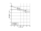
- FIG. 2 is a diagram showing the relationship between the number of cycles of the secondary battery in the battery pack according to the embodiment of the present invention and the end-of-charge voltage in the high capacity mode or the long life mode.
- the horizontal axis represents the number of cycles (seconds) of the secondary battery 11, and the vertical axis represents the charge end voltage (V / Cell) in the high capacity mode or the long life mode.
- the high capacity mode is indicated by a solid line
- the long life mode is indicated by a broken line.
- the charge end voltage is set to the first voltage (4.2 V / cell) to perform charging. Then, as the number of cycles of the secondary battery 11 increases, control is performed to gradually reduce the charge end voltage from the first voltage (for example, 4.2 V / cell). Thereby, after the cycle number of the secondary battery 11 increases and it deteriorates, the further deterioration by overcharge can be prevented.
- the charge end voltage is set to the first charge voltage so that the capacity of the secondary battery 11 becomes a predetermined ratio (for example, 80%) of the standard capacity. Charging is performed at a second voltage (for example, 4.0 V / cell) lower than the voltage (4.2 V / cell).
- a second voltage for example, 4.0 V / cell
- the secondary battery 11 can ensure a certain level of capacity, and since the secondary battery 11 is not fully charged, it can be used with a longer life than the high capacity mode as shown in FIG. it can.
- the capacity at which the relative remaining capacity is 100% in the high capacity mode approaches a predetermined ratio (for example, 80%) of the standard capacity of the secondary battery 11, as shown in FIG.
- the first voltage approaches the second voltage as the end-of-charge voltage.
- the end-of-charge voltage in the long life mode is controlled to gradually decrease as the number of cycles increases as in the high capacity mode as shown in FIG. .
- the first voltage that is the charge end voltage in the high capacity mode is the second voltage that is the charge end voltage in the long life mode. (For example, 4.0V / cell).
- the difference between the charge end voltage in the high capacity mode and the charge end voltage in the long life mode becomes a predetermined voltage, for example, 0.065 V or less
- the charge end voltage in the long life mode is the same as that in the high capacity mode as shown in FIG.
- the control is performed to gradually decrease as the number of cycles increases.
- the difference between the charge end voltage in the high capacity mode and the charge end voltage in the long life mode is set to a predetermined voltage, for example, 0.065 V, and is reduced in parallel as shown in FIG.
- the first voltage that is the charge termination voltage in the high capacity mode is fixed at 3.9 V / cell, for example. Thereafter, even if the number of cycles increases, the end-of-charge voltage is maintained at 3.9 V / cell.
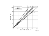
- FIG. 3 is a diagram showing changes in capacity and relative remaining capacity in the high capacity mode or long life mode of the battery pack according to the embodiment of the present invention.
- the horizontal axis is the ratio (RC / FCC int ) (%) of the remaining capacity (RC) after the cycle with respect to the standard capacity (initial FCC) of the secondary battery 11, and the vertical axis is the cycle in the high capacity mode or long life mode. Relative remaining capacity (%) after elapse.
- the high capacity mode is indicated by a solid line
- the long life mode is indicated by a broken line.
- FIG. 3 shows the capacity of the high capacity mode and the long life mode in the initial state (point A) of the secondary battery 11 and three states (points B, C, and D) in which the secondary battery has deteriorated after the number of cycles has elapsed. And the relative remaining capacity.
- the full charge capacity of the secondary battery 11 will be described.
- the full charge capacity is 100%, 85%, 80%, 65% of the standard capacity, and the four timings in the high capacity mode are solid lines connecting points 0 and A to D.
- a broken line connecting the 0 point and the points a to b is shown. These timings are also indicated by the same reference numerals (points A to D and points a and b) in FIG.
- the relative remaining capacity (RSOC HC ) in the high capacity mode varies between 0 and 100%
- the relative remaining capacity (RSOC LL ) in the long life mode varies between 0 and 80%. Equation 2 is obtained.
- the relative remaining capacity (RSOC HC ) in the high capacity mode and the relative remaining capacity (RSOC LL ) in the long life mode are the standard capacity of the secondary battery 11.
- the full charge capacity of the secondary battery 11 is gradually lowered as indicated by the arrow 1 in the high capacity mode as the number of cycles advances and the secondary battery 11 deteriorates.
- the capacity of the secondary battery 11 is 85% of the standard capacity
- 85% of the relative remaining capacity (RSOC HC ) in the high capacity mode is It becomes the ratio (RC / FCC int ) between the standard capacity and the remaining capacity.
- the ratio is equal to the ratio of the standard capacity and the remaining capacity of the secondary battery 11 (RC / FCC int ).
- the relative remaining capacity in the high capacity mode and the relative remaining capacity in the long life mode are different from the initial state of the secondary battery 11 to the vicinity of 80% of the standard capacity (for example, 83%).
- X is a coefficient).
- the end-of-charge voltage in the long life mode is reduced in the same manner as in the high capacity mode.
- a point C and a point c in FIG. 3 in which the capacity of the secondary battery 11 is 80% of the standard capacity 80% of the relative capacity (RSOC HC ) in the high capacity mode is the secondary battery 11.
- the ratio between the standard capacity and the remaining capacity RC / FCC int ).
- the high capacity 65% of the relative remaining capacity (RSOC HC ) of the mode is the ratio (RC / FCC int ) between the standard capacity of the secondary battery 11 and the remaining capacity.
- the relative remaining capacity in the high capacity mode and the relative remaining capacity in the long life mode can be obtained by the following calculation formulas. (Y and z are coefficients).
- the remaining capacity calculation unit 15d calculates the relative remaining capacity according to the characteristics of the relative remaining capacity with respect to the ratio of the standard capacity and the remaining capacity of the secondary battery 11 in the operation mode before switching. calculate. Then, after reaching the charge end voltage in the operation mode after switching by charging, the remaining capacity calculation unit 15d performs relative relative to the characteristics of the relative remaining capacity with respect to the ratio of the standard capacity and the remaining capacity of the secondary battery 11 in the operation mode after switching. Calculate the remaining capacity.
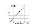
- FIG. 4 is a diagram showing a change in relative remaining capacity when the battery pack according to the embodiment of the present invention is switched from the high capacity mode to the long life mode
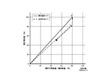
- FIG. 5 is a battery according to the embodiment of the present invention. It is a figure which shows the change of the relative remaining capacity when switching from the long life mode of a pack to a high capacity
- Fig. 4 shows a case where charging is performed by switching from the high capacity mode to the long life mode at the position of the black circle.
- the operation mode Immediately after the switching of the operation mode, it follows the characteristic of the relative remaining capacity with respect to the ratio of the standard capacity and the remaining capacity of the secondary battery 11 in the high capacity mode before switching, and therefore, along a straight line connecting the 0 point and the C point as indicated by a dotted arrow.
- the relative remaining capacity increases.
- the relative remaining capacity becomes 80%
- the relative remaining capacity becomes 80%, which is the maximum value of the relative remaining capacity in the long life mode after switching, as the dotted arrow bends in the horizontal axis direction.
- the relative remaining capacity may be maintained at 79%, and after the charge end voltage is reached, the relative remaining capacity may be changed to 80% to terminate the charging.
- the remaining capacity calculation unit 15d sets the relative remaining capacity with respect to the ratio of the standard capacity and the remaining capacity of the secondary battery 11 to 80% when the end-of-charge voltage at the point c in FIG. 4 is reached. Then, until the next operation mode is switched, the remaining capacity calculation unit 15d has a characteristic of the relative remaining capacity with respect to the ratio of the standard capacity and the remaining capacity of the secondary battery 11 due to charging / discharging along a straight line connecting the 0 point and the c point. calculate.
- Fig. 5 shows the case where charging is performed by switching from the long life mode to the high capacity mode at the position of the black circle.
- the operation mode Immediately after the switching of the operation mode, it follows the characteristic of the relative remaining capacity with respect to the ratio of the standard capacity and the remaining capacity of the secondary battery 11 in the long life mode before switching, and therefore follows a straight line connecting the 0 point and the c point as indicated by a dotted arrow.
- the relative remaining capacity changes. Even after the relative remaining capacity reaches 80%, the relative remaining capacity increases on the extended line connecting the 0 point and the c point. Then, after reaching the end-of-charge voltage, the relative remaining capacity is rapidly increased to 100%, and the charging is terminated.
- the remaining capacity calculation unit 15d sets the relative remaining capacity with respect to the ratio between the standard capacity and the remaining capacity of the secondary battery 11 at the time when the end-of-charge voltage, which is point C in FIG. Then, until the next operation mode is switched, the remaining capacity calculation unit 15d has a characteristic of the relative remaining capacity with respect to the ratio of the standard capacity and the remaining capacity of the secondary battery 11 due to charging / discharging along a straight line connecting the 0 point and the C point. calculate.
- the relative remaining capacity is maintained at 80% only in the vicinity of one full charge immediately after switching.
- the relative remaining capacity can be accurately displayed at a timing when there is little remaining capacity that requires attention to the state of charge.
- timing at point C in FIG. 3 has been described as an example, the same processing is performed when switching the operation mode at timings when the characteristics of the high capacity mode and the long life mode are different at points B, C, D and other timings. .
- the relative remaining capacity of the secondary battery is determined according to the operation mode. Furthermore, it is possible to provide a battery pack that can be accurately obtained even when the operation mode is changed.
- the end-of-charge voltage is linearly reduced with respect to the number of cycles as shown in FIG. 2, but it may be reduced in a curved line. Alternatively, it may be reduced stepwise. Alternatively, the end-of-charge voltage may be reduced by a straight line or curve different from the initial, middle, and final stages according to the characteristics of the battery used. In particular, as shown in FIG. 6, it is possible to suppress the subsequent deterioration of the secondary battery by greatly reducing the end-of-charge voltage from the initial stage to 100 to 200 cycles.
- the end-of-charge voltage is reduced with respect to the number of cycles as shown in FIG. 2, but the end-of-charge voltage may be reduced with respect to the number of elapsed days. In that case, the end-of-charge voltage is reduced according to the number of days information input from the electronic device.
- the charge end voltage may be reduced with respect to the number of cycles in the first half of use, and the charge end voltage may be reduced with respect to the number of days of use in the second half of use.
- the first voltage in the high capacity mode in the initial secondary battery is 4.2 V / cell at which the secondary battery has the maximum full charge capacity, but the first voltage is the second voltage.
- the full charge capacity may be set to 85 to 99% of the maximum full charge capacity of the secondary battery.
- the battery pack according to the present invention controls the relative remaining capacity of the secondary battery according to the operation mode while suppressing deterioration due to overcharge of the secondary battery that is selected and set to the high capacity mode or the long life mode.
- it since it can be obtained accurately even when the operation mode is changed, it is useful as a battery pack, a battery system or the like for switching the operation mode.
Landscapes
- Engineering & Computer Science (AREA)
- Chemical & Material Sciences (AREA)
- Manufacturing & Machinery (AREA)
- Chemical Kinetics & Catalysis (AREA)
- Electrochemistry (AREA)
- General Chemical & Material Sciences (AREA)
- Power Engineering (AREA)
- Charge And Discharge Circuits For Batteries Or The Like (AREA)
- Secondary Cells (AREA)
- Battery Mounting, Suspending (AREA)
- Materials Engineering (AREA)
Abstract
Description
RSOC=RC/FCC (1)
0% ≦ RSOCHC ≦ 100% (2)
0% ≦ RSOCLL ≦ 80%
RSOCHC = RSOCLL = RC/FCCint (3)
RSOCHC × 0.85 = RSOCLL = RC/FCCint (4)
RSOCHC × x = RSOCLL = RC/FCCint (5)
0.80 < x ≦ 1.0
RSOCHC × 0.80 = RSOCLL × 0.94 = RC/FCCint (6)
RSOCHC × 0.65 = RSOCLL × 0.78 = RC/FCCint (7)
RSOCHC × y = RSOCLL × z = RC/FCCint (8)
y < 0.85
z < 1.0
11 二次電池
12 制御部
13 スイッチ素子
14 電流検出部
15 制御・演算部
15a 動作モード設定部
15b 充放電制御部
15c サイクル数算出部
15d 残容量算出部
16 電圧検出部
17 通信処理部
18 メモリ
19 温度検出素子
20 電子機器
21 負荷
22 制御・電源部
Claims (7)
- 二次電池と、
前記二次電池の充放電を制御する制御演算部とを備え、
前記制御演算部は、
前記二次電池の充電終止電圧を第1の電圧に制限して前記二次電池の満充電容量を高くする高容量モード、または前記充電終止電圧を前記第1の電圧よりも低い第2の電圧に制限して前記二次電池のサイクル寿命を長くする長寿命モードを選択設定する動作モード設定部と、
前記二次電池の放電電流と放電時間または放電電流と電池電圧に基づいて前記二次電池の残容量を求め、前記残容量と前記二次電池の満充電容量とから前記二次電池の相対残容量を算出する残容量算出部と、
前記残容量算出部での算出結果から前記二次電池のサイクル数を算出するサイクル数算出部と、
前記サイクル数に基づいて前記第1の電圧を低減させ、前記第1の電圧が前記第2の電圧に所定の電圧を加算した値以下になったとき、前記第2の電圧を前記第1の電圧から所定の電圧を減算した電圧にする充電終止電圧設定部とを有することを特徴とする電池パック。 - 前記残容量算出部は、
前記高容量モードが設定されたときには、前記二次電池の規格容量または充電終止電圧での充電容量を満充電容量として用い、
前記長寿命モードが設定されたときで前記第1の電圧が前記第2の電圧に所定の電圧を加算した値より大きいときには、前記規格容量に100%以下の所定の係数を乗じた容量を前記長寿命モードでの最大充電容量として用い、
前記長寿命モードが設定されたときで前記第1の電圧が前記第2の電圧に所定の電圧を加算した値以下のときには、前記第2の電圧での充電容量を前記長寿命モードでの最大充電容量として用いる請求項1に記載の電池パック。 - 前記残容量算出部は、
動作モードが変更された直後は、変更前の動作モードにおける算出方法で相対残容量を算出し、充電で変更後の動作モードの充電終止電圧になった後、切換後の動作モードにおける算出方法で相対残容量を算出する請求項2に記載の電池パック。 - 前記残容量算出部は、
動作モードが前記高容量モードから前記長寿命モードに変更された後の最初の満充電付近の充電において、最大値を前記所定の係数に制限して前記相対残容量を求める請求項3に記載の電池パック。 - 前記残容量算出部は、
動作モードが前記長寿命モードから前記高容量モードに変更された後の最初の満充電付近の充電において、前記充電終止電圧になったとき前記相対残容量を100%に変更する請求項3に記載の電池パック。 - 前記残容量算出部は、
前記高容量モードにおいて、前記満充電容量を相対残容量100%とし、
前記長寿命モードにおいて、前記最大充電容量を相対残容量が前記所定の係数とする請求項2に記載の電池パック。 - 前記二次電池は、リチウムイオン電池であって、
前記二次電池の使用状態が初期のときに、前記高容量モードでの充電終止電圧を規制する前記第1の電圧は4.2V/cellとして設定され、前記長寿命モードでの充電終止電圧を規制する前記第2の電圧は3.9~4.1V/cellとして設定される請求項1に記載の電池パック。
Priority Applications (3)
| Application Number | Priority Date | Filing Date | Title |
|---|---|---|---|
| US14/778,587 US9780592B2 (en) | 2013-11-29 | 2014-09-08 | Battery pack for selectively setting a high capacity mode having a high charge capacity until a full charge of a secondary battery |
| CN201480002221.0A CN104813560B (zh) | 2013-11-29 | 2014-09-08 | 电池组 |
| JP2015501984A JP5971397B2 (ja) | 2013-11-29 | 2014-09-08 | 電池パック |
Applications Claiming Priority (2)
| Application Number | Priority Date | Filing Date | Title |
|---|---|---|---|
| JP2013-247138 | 2013-11-29 | ||
| JP2013247138 | 2013-11-29 |
Publications (1)
| Publication Number | Publication Date |
|---|---|
| WO2015079607A1 true WO2015079607A1 (ja) | 2015-06-04 |
Family
ID=53198587
Family Applications (1)
| Application Number | Title | Priority Date | Filing Date |
|---|---|---|---|
| PCT/JP2014/004592 Ceased WO2015079607A1 (ja) | 2013-11-29 | 2014-09-08 | 電池パック |
Country Status (4)
| Country | Link |
|---|---|
| US (1) | US9780592B2 (ja) |
| JP (1) | JP5971397B2 (ja) |
| CN (1) | CN104813560B (ja) |
| WO (1) | WO2015079607A1 (ja) |
Families Citing this family (17)
| Publication number | Priority date | Publication date | Assignee | Title |
|---|---|---|---|---|
| WO2016051722A1 (ja) * | 2014-09-29 | 2016-04-07 | 日本電気株式会社 | 蓄電装置、制御装置、蓄電システム、蓄電装置の制御方法および制御プログラムを格納した非一時的なコンピュータ可読媒体 |
| CN104734281B (zh) * | 2015-01-28 | 2019-04-16 | 惠州Tcl移动通信有限公司 | 可穿戴移动电源及其供电控制方法 |
| JP6536466B2 (ja) * | 2016-04-27 | 2019-07-03 | 株式会社オートネットワーク技術研究所 | 電源装置 |
| KR102503430B1 (ko) * | 2017-10-26 | 2023-02-28 | 삼성전자주식회사 | 배터리를 포함하는 전자 장치 |
| US10666077B1 (en) * | 2017-11-01 | 2020-05-26 | Amazon Technologies, Inc. | Remote configuration of battery charging settings |
| KR102103454B1 (ko) | 2018-07-18 | 2020-04-23 | 삼화콘덴서공업 주식회사 | 하이브리드 어셈블리 구조를 가지는 배터리 커패시터 |
| CN109586359A (zh) * | 2018-11-09 | 2019-04-05 | 金龙联合汽车工业(苏州)有限公司 | 电池过充预警方法和装置 |
| CN111416398B (zh) * | 2019-01-08 | 2023-11-14 | 太普动力新能源(常熟)股份有限公司 | 可充电电池的相对荷电状态的修正方法 |
| EP3993205A4 (en) * | 2019-06-27 | 2022-08-31 | SANYO Electric Co., Ltd. | BATTERY PACK AND ANOMALITY MONITORING PROCEDURE THEREOF |
| CN112542861B (zh) | 2019-09-23 | 2023-05-30 | 北京小米移动软件有限公司 | 一种电池充电方法、装置及介质 |
| CN112698225B (zh) | 2019-10-22 | 2022-05-13 | 华为技术有限公司 | 一种电池容量跟踪方法、装置及电子设备 |
| CN112379296B (zh) * | 2020-10-09 | 2025-10-14 | 河北格力钛新能源有限公司 | 锂电池循环寿命的测试方法、测试装置和测试系统 |
| US11662391B1 (en) * | 2020-10-19 | 2023-05-30 | Amazon Technologies, Inc. | Dynamic adjustments to battery parameters using battery metrics |
| KR20220116866A (ko) * | 2021-02-16 | 2022-08-23 | 삼성전자주식회사 | 전자 장치 및 그 제어 방법 |
| CN115508731B (zh) * | 2021-06-23 | 2025-07-15 | 宇通客车股份有限公司 | 电池寿命保护方法 |
| EP4293860A1 (en) * | 2022-06-15 | 2023-12-20 | Braun GmbH | Personal care device with a rechargeable energy source |
| US12556024B1 (en) * | 2022-11-22 | 2026-02-17 | Amazon Technologies, Inc. | Dynamic adjustments to battery charging using battery metrics |
Citations (5)
| Publication number | Priority date | Publication date | Assignee | Title |
|---|---|---|---|---|
| JPH07255133A (ja) * | 1994-03-15 | 1995-10-03 | Nissan Motor Co Ltd | 2次電池の充放電制御装置 |
| JP2001309568A (ja) * | 2000-04-26 | 2001-11-02 | Internatl Business Mach Corp <Ibm> | 充電システム、充電制御装置、充電制御方法及びコンピュータ |
| JP2002078222A (ja) * | 2000-08-31 | 2002-03-15 | Sanyo Electric Co Ltd | リチウムイオン二次電池の充電回路とパック電池 |
| JP2002359008A (ja) * | 2001-03-28 | 2002-12-13 | Japan Storage Battery Co Ltd | 二次電池の運用方法及び二次電池装置 |
| JP2011125108A (ja) * | 2009-12-09 | 2011-06-23 | Sanyo Electric Co Ltd | パック電池 |
Family Cites Families (5)
| Publication number | Priority date | Publication date | Assignee | Title |
|---|---|---|---|---|
| CN100438204C (zh) * | 2002-12-05 | 2008-11-26 | 松下电器产业株式会社 | 电池组及其充放电方法 |
| JP4144568B2 (ja) * | 2004-06-04 | 2008-09-03 | ソニー株式会社 | バッテリ残量検出システム、電子機器及びバッテリパック |
| CN101388562B (zh) * | 2008-07-10 | 2010-10-13 | 广州丰江电池新技术有限公司 | 快速充电方法 |
| US20110234167A1 (en) * | 2010-03-24 | 2011-09-29 | Chin-Hsing Kao | Method of Predicting Remaining Capacity and Run-time of a Battery Device |
| WO2013128810A1 (ja) * | 2012-02-29 | 2013-09-06 | Necエナジーデバイス株式会社 | 電池制御システム、電池パック、電子機器 |
-
2014
- 2014-09-08 JP JP2015501984A patent/JP5971397B2/ja active Active
- 2014-09-08 US US14/778,587 patent/US9780592B2/en active Active
- 2014-09-08 CN CN201480002221.0A patent/CN104813560B/zh active Active
- 2014-09-08 WO PCT/JP2014/004592 patent/WO2015079607A1/ja not_active Ceased
Patent Citations (5)
| Publication number | Priority date | Publication date | Assignee | Title |
|---|---|---|---|---|
| JPH07255133A (ja) * | 1994-03-15 | 1995-10-03 | Nissan Motor Co Ltd | 2次電池の充放電制御装置 |
| JP2001309568A (ja) * | 2000-04-26 | 2001-11-02 | Internatl Business Mach Corp <Ibm> | 充電システム、充電制御装置、充電制御方法及びコンピュータ |
| JP2002078222A (ja) * | 2000-08-31 | 2002-03-15 | Sanyo Electric Co Ltd | リチウムイオン二次電池の充電回路とパック電池 |
| JP2002359008A (ja) * | 2001-03-28 | 2002-12-13 | Japan Storage Battery Co Ltd | 二次電池の運用方法及び二次電池装置 |
| JP2011125108A (ja) * | 2009-12-09 | 2011-06-23 | Sanyo Electric Co Ltd | パック電池 |
Also Published As
| Publication number | Publication date |
|---|---|
| JP5971397B2 (ja) | 2016-08-17 |
| US9780592B2 (en) | 2017-10-03 |
| US20160197506A1 (en) | 2016-07-07 |
| CN104813560A (zh) | 2015-07-29 |
| JPWO2015079607A1 (ja) | 2017-03-16 |
| CN104813560B (zh) | 2017-06-13 |
Similar Documents
| Publication | Publication Date | Title |
|---|---|---|
| JP5971397B2 (ja) | 電池パック | |
| CN102097835B (zh) | 组式电池 | |
| JP4966998B2 (ja) | 充電制御回路、電池パック、及び充電システム | |
| CN101611525B (zh) | 充电系统、充电装置以及电池组件 | |
| KR102160272B1 (ko) | 배터리 관리 장치 및 이를 이용한 lfp 셀의 과전압 보호 방법 | |
| JP5638779B2 (ja) | 二次電池の特性検出方法および二次電池装置 | |
| JP5461482B2 (ja) | 電池システム | |
| JP5091634B2 (ja) | 電池パック、及び充電システム | |
| JP5410248B2 (ja) | 二次電池の寿命期間を保証する充電システム | |
| JP5119307B2 (ja) | バッテリーパックの充電制御方法 | |
| US10505477B2 (en) | Load drive current control method and system | |
| JP2011053088A (ja) | 二次電池の残容量演算方法および二次電池装置 | |
| JP2011015481A (ja) | 充電制御方法、充電制御装置およびパック電池 | |
| JP2013013258A (ja) | 二次電池の充電方法、充電制御装置及びパック電池 | |
| JP2011004509A5 (ja) | ||
| JP2004357481A (ja) | 複数のバッテリを充電する方法と放電する方法 | |
| JP2009225632A (ja) | 充電制御回路、電池パック、及び充電システム | |
| WO2013008409A1 (ja) | 電池パックの製造方法および電池パック | |
| JP6824295B2 (ja) | 電気機器 | |
| EP3934002B1 (en) | Battery pack charging method, battery pack and power source device | |
| JP5489779B2 (ja) | リチウムイオン組電池の充電システムおよび充電方法 | |
| JP5165405B2 (ja) | 充電制御回路、電池パック、及び充電システム | |
| JP2011038878A (ja) | 二次電池の劣化度判定方法および二次電池装置 | |
| JP4796784B2 (ja) | 2次電池の充電方法 | |
| JP2014522222A (ja) | 電気蓄電池を平衡化するための方法およびデバイス |
Legal Events
| Date | Code | Title | Description |
|---|---|---|---|
| ENP | Entry into the national phase |
Ref document number: 2015501984 Country of ref document: JP Kind code of ref document: A |
|
| 121 | Ep: the epo has been informed by wipo that ep was designated in this application |
Ref document number: 14865032 Country of ref document: EP Kind code of ref document: A1 |
|
| WWE | Wipo information: entry into national phase |
Ref document number: 14778587 Country of ref document: US |
|
| NENP | Non-entry into the national phase |
Ref country code: DE |
|
| 122 | Ep: pct application non-entry in european phase |
Ref document number: 14865032 Country of ref document: EP Kind code of ref document: A1 |