WO2015075952A1 - 画像処理装置、画像処理方法、及び制御プログラム - Google Patents
画像処理装置、画像処理方法、及び制御プログラム Download PDFInfo
- Publication number
- WO2015075952A1 WO2015075952A1 PCT/JP2014/050489 JP2014050489W WO2015075952A1 WO 2015075952 A1 WO2015075952 A1 WO 2015075952A1 JP 2014050489 W JP2014050489 W JP 2014050489W WO 2015075952 A1 WO2015075952 A1 WO 2015075952A1
- Authority
- WO
- WIPO (PCT)
- Prior art keywords
- image
- transmittance
- unit
- range
- pixel
- Prior art date
- Legal status (The legal status is an assumption and is not a legal conclusion. Google has not performed a legal analysis and makes no representation as to the accuracy of the status listed.)
- Ceased
Links
Images

Classifications
-
- H—ELECTRICITY
- H04—ELECTRIC COMMUNICATION TECHNIQUE
- H04N—PICTORIAL COMMUNICATION, e.g. TELEVISION
- H04N1/00—Scanning, transmission or reproduction of documents or the like, e.g. facsimile transmission; Details thereof
- H04N1/40—Picture signal circuits
- H04N1/409—Edge or detail enhancement; Noise or error suppression
- H04N1/4092—Edge or detail enhancement
-
- G—PHYSICS
- G06—COMPUTING OR CALCULATING; COUNTING
- G06T—IMAGE DATA PROCESSING OR GENERATION, IN GENERAL
- G06T5/00—Image enhancement or restoration
- G06T5/40—Image enhancement or restoration using histogram techniques
-
- G—PHYSICS
- G06—COMPUTING OR CALCULATING; COUNTING
- G06T—IMAGE DATA PROCESSING OR GENERATION, IN GENERAL
- G06T5/00—Image enhancement or restoration
- G06T5/90—Dynamic range modification of images or parts thereof
-
- G—PHYSICS
- G06—COMPUTING OR CALCULATING; COUNTING
- G06T—IMAGE DATA PROCESSING OR GENERATION, IN GENERAL
- G06T2207/00—Indexing scheme for image analysis or image enhancement
- G06T2207/20—Special algorithmic details
- G06T2207/20016—Hierarchical, coarse-to-fine, multiscale or multiresolution image processing; Pyramid transform
Definitions
- the present invention relates to an image processing apparatus, an image processing method, and a control program for removing fog in an image.
- Non-Patent Document 1 As an image processing method for removing fog in an image, for example, a method described in Non-Patent Document 1 is known.
- the image processing apparatus divides the pixel value (R, G, B) of each pixel (each pixel) of the input image by the pixel value (R, G, B) of the atmospheric light. Correct. Further, the image processing apparatus estimates the fog density of the corrected input image using the minimum values of R, G, and B in a local region called a dark channel (Dark Channel). Then, the image processing apparatus calculates the coarse transmittance from the fog density. Furthermore, the image processing apparatus calculates a finely accurate transmittance using a technique called soft matting. The image processing apparatus removes fog in the image using this transmittance.
- the image processing apparatus obtains a dark channel in the local region.
- This local region is preferably a region where the transmittance is considered to be constant.
- a region having a predetermined size centered on a pixel for which a dark channel is obtained is used. For this reason, the transmittance in the local region is not constant but uneven. Therefore, in the method of Non-Patent Document 1 described above, the image processing apparatus performs the equalization process by soft matting, but soft matting has a high processing load and takes a long processing time.
- the present invention has been made in view of the above-described circumstances, and an object thereof is to provide an image processing apparatus, an image processing method, and a control program for removing fog in an image at high speed with a low processing load.
- a dark channel image generation unit that generates a dark channel image based on an input image, a dark channel image generated by the dark channel image generation unit, and an atmospheric light pixel value are used.
- a transmittance image generating unit for generating a transmittance image, a transmittance correcting unit for correcting the transmittance image generated by the transmittance image generating unit, a transmittance image corrected by the transmittance correcting unit, and an atmospheric light pixel There is provided an image processing apparatus including a fog removal image generation unit that removes fog in an input image based on a value and an input image.
- the transmittance correction unit divides the transmittance image into predetermined regions, performs binarization based on the average value of the transmittance of each pixel in each divided predetermined region, and binarizes in each predetermined region.
- the transmittance of each pixel in each predetermined region is selected on the basis of the number of each value thus obtained and the average value of the transmittance of each value in each predetermined region. According to such a configuration, it is possible to make the transmittance uniform without applying a processing burden compared to soft matting.
- the transmittance correction unit performs a morphological process on the transmittance image. Even with such a configuration, it is possible to make the transmittance uniform without imposing a processing burden.
- the transmittance of each pixel of the transmittance image corrected by the transmittance correcting unit is multiplied by the transmittance of each pixel of the transmittance image generated by the transmittance image generating unit, and the multiplied value
- a transmittance shaping unit that shapes the transmittance image by performing a square root calculation, and the fog removal image generation unit is based on the transmittance image, the atmospheric light pixel value, and the input image shaped by the transmittance shaping unit. Remove fog in the input image. According to such a configuration, it is possible to suppress the occurrence of halos when the transmittance image is corrected by the transmittance correcting unit.
- the present invention further includes a range correction unit that expands the range of the input image, and the dark channel image generation unit generates a dark channel image based on the image whose range is expanded by the range correction unit, and generates a fog removal image.
- the unit removes fog in the image based on the transmittance image corrected by the transmittance correction unit, the atmospheric light pixel value, and the image whose range is expanded by the range correction unit. According to such a configuration, it is possible to reduce the fog in the image by expanding the dynamic range of the input image.
- the range correction unit includes a first range correction unit that expands the range of the area of the input image, and a second range that divides the input image into a plurality of areas and expands the range of the plurality of divided areas.
- the synthesis unit multiplies the image whose range has been expanded by the first range correction unit by the first coefficient, and multiplies the image whose range has been expanded by the second range correction unit by the second coefficient, Add the images. According to such a configuration, it is possible to combine images after weighting each image.
- the second range correction unit performs an interpolation process on an image whose range has been expanded. Therefore, continuity of pixel values can be provided between the divided areas.
- an image processing method for removing fog in an image a dark channel image generation step for generating a dark channel image based on an input image, a dark channel image generated by the dark channel image generation step, and an atmospheric air
- An image processing method including a fog removal image generation step of removing fog in the input image based on the rate image, the atmospheric light pixel value, and the input image is provided.
- the arithmetic unit of the image processing device is configured to generate a dark channel image based on the input image, and based on the dark channel image generated by the dark channel image generation processing and the atmospheric light pixel value.
- Transmittance image generation processing for generating a transmittance image
- transmittance correction processing for correcting the transmittance image generated by the transmittance image generation processing
- transmittance image corrected by the transmittance correction processing and atmospheric light pixels
- a control program for executing fog removal image generation processing for removing fog in the input image based on the value and the input image.
- fog in an image can be removed at high speed with a low processing load.
- FIG. 1 is a block diagram illustrating a configuration of an image processing apparatus according to a first embodiment. It is a block diagram which shows the structure of the dynamic range correction
- FIG. 1 is a block diagram illustrating a configuration of an image processing apparatus 1 according to the first embodiment.
- An image processing apparatus 1 shown in FIG. 1 is an apparatus that performs processing for removing fog in an image as image processing.
- fog refers to a phenomenon in which visibility is reduced due to fine water particles floating in the atmosphere.
- the fog is also called moth or mist.
- it is not limited to fog, and includes a phenomenon in which a subject in an image becomes difficult to see due to fine particles in the atmosphere.
- the image includes a still image and a moving image. As shown in FIG.
- the image processing apparatus 1 includes a dynamic range correction unit (range correction unit) 10, an atmospheric light pixel value calculation unit (dark channel image generation unit) 20, and a transmittance calculation unit (transmittance image generation unit). 30, a transmittance correction unit 40, a transmittance shaping unit 50, and a fog removal image generation unit 60.
- the dynamic range correction unit 10 performs processing (preprocessing) for expanding the dynamic range of an image. By performing such processing, fog in the image is reduced.
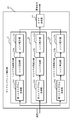
- FIG. 2 is a block diagram showing a configuration of the dynamic range correction unit 10 shown in FIG.
- the dynamic range correction unit 10 includes an 1-area division enlargement unit (first range correction unit) 11, a 4-area division enlargement unit (second range correction unit) 12, and a 9-area division enlargement unit (second A range correction unit 13 and an area composition unit (composition unit) 14 are provided.
- the pixel value of each pixel of the input image branches in the middle and is output to the 1-area division enlargement unit 11, the 4-area division enlargement unit 12, and the 9-area division enlargement unit 13, respectively.
- the 1-area division enlargement unit 11 enlarges the dynamic range of the entire area of the input image.
- the one-area division enlargement unit 11 includes a first histogram generation unit 11a, a range calculation unit 11b, and a range enlargement unit 11c.
- the first histogram generator 11a generates a histogram of the entire area of the input image.
- the histogram is a table showing how many pixels have what brightness (see FIG. 5).
- the range calculation unit 11b removes (deletes) noise components of the input image using the histogram of the entire area of the input image generated by the first histogram generation unit 11a.
- the range enlarging unit 11c performs range enlarging processing for enlarging the range from which the noise component of the input image is removed by the range calculating unit 11b to a predetermined range. Then, the range expansion unit 11c outputs the pixel value of each pixel after the range expansion to the area composition unit 14.
- the 4-area division / enlargement unit 12 divides the area of the input image into four areas (areas), and expands the dynamic range of each of the divided four areas.
- the four-area divided enlargement unit 12 includes a second histogram generation unit 12a, a range calculation unit 12b, and a range enlargement unit 12c.
- the second histogram generation unit 12a divides the area of the input image into four areas, and generates a histogram for each of the four divided areas.
- the range calculation unit 12b removes (deletes) noise components of the four regions using the histograms of the four regions generated by the second histogram generation unit 12a.
- the range enlarging unit 12c performs a range enlarging process in which the ranges of the four regions from which the noise component is removed by the range calculating unit 12b are each expanded to a predetermined range.
- the range expansion unit 11c performs continuity of pixel values after range expansion by performing bilinear interpolation processing between regions in the range expansion processing. Then, the range expansion unit 12 c outputs the pixel value of each pixel after the range expansion to the area composition unit 14.
- the 9 area division / enlargement unit 13 divides the area of the input image into 9 areas (areas), and expands the dynamic range of each of the divided 9 areas.
- the nine-area divided enlargement unit 13 includes a third histogram generation unit 13a, a range calculation unit 13b, and a range enlargement unit 13c.
- the third histogram generation unit 13a divides the area of the input image into nine areas, and generates a histogram for each of the nine divided areas.
- the range calculation unit 13b removes (deletes) the noise components of each of the nine regions using the histogram of the nine regions generated by the third histogram generation unit 13a.
- the range expansion unit 13c performs a range expansion process for expanding the ranges of the nine regions from which the noise component has been removed by the range calculation unit 13b to respective predetermined ranges. In addition, the range expansion unit 13c performs continuity of pixel values after range expansion by performing bilinear interpolation processing between regions in the range expansion processing. Then, the range expansion unit 13 c outputs the pixel value of each pixel after the range expansion to the area composition unit 14.
- the area synthesis unit 14 synthesizes the pixel values after the dynamic range is expanded by the 1-area division enlargement unit 11, the 4-area division enlargement unit 12, and the 9-area division enlargement unit 13. Specifically, the area composition unit 14 inputs the pixel value of each pixel after range expansion from each area division enlargement unit 11, 12, 13. Then, the area composition unit 14 multiplies the input pixel value by a predetermined coefficient, and adds the multiplied values. The pixel value of each pixel synthesized by the area synthesis unit 14 is output to the atmospheric light pixel value calculation unit 20 and the fog removal image generation unit 60.
- the atmospheric light pixel value calculation unit 20 generates a dark channel image based on the pixel value of each pixel of the fog image (image including fog) output from the dynamic range correction unit 10.
- the atmospheric light pixel value calculation unit 20 calculates the atmospheric light pixel value of the fog image.
- Atmospheric light is light scattered by particles in the atmosphere. Among the pixel values of the image, the component of scattered light due to particles in the atmosphere is the atmospheric light pixel value.
- the atmospheric light pixel value calculation unit 20 uses the smallest value (the minimum value among the R, G, and B channels) of each pixel as the representative value ( A dark channel image is generated as a dark channel value.
- the values of all channels of all pixels in the local region (15 ⁇ 15 pixel region) are set.
- the minimum value is the dark channel value
- the dark channel value (minJ C (y)) of each pixel is used as it is. In this way, the process is simplified by using the dark channel value of each pixel instead of using the minimum value of all the channel values of all the pixels in the local region (15 ⁇ 15 pixel region). Has been realized.
- the atmospheric light pixel value calculation unit 20 sets the pixel value having the smallest representative value (dark channel value) in the entire area of the input image as the atmospheric light pixel value.
- the atmospheric light pixel value calculation unit 20 calculates one atmospheric light pixel value for the entire area of the input image.
- the atmospheric light pixel value calculation unit 20 outputs the pixel value and the atmospheric light pixel value of each pixel of the dark channel image to the transmittance calculation unit 30 and the fog removal image generation unit 60.
- the transmittance calculation unit 30 calculates the transmittance of each pixel using the pixel value and the atmospheric light pixel value of each pixel of the dark channel image from the atmospheric light pixel value calculation unit 20. That is, the transmittance calculation unit 30 calculates the transmittance (dtrans) for each pixel by substituting the dark channel value (Dark) and the atmospheric light pixel value (A) for each pixel into the following equation (1). .
- ⁇ is a parameter for controlling the strength of fog removal.
- the transmittance calculation unit 30 generates a transmittance image from the transmittance of each pixel. Then, the transmittance calculation unit 30 outputs the transmittance image (transmittance of each pixel) to the transmittance correction unit 40 and the transmittance shaping unit 50.
- the transmittance correcting unit 40 corrects the transmittance image (initial transmittance image) output from the transmittance calculating unit 30. Specifically, the transmittance correction unit 40 uniformizes the transmittance of the initial transmittance image by dilation and generates a transmittance uniform image. Further, the transmittance correction unit 40 generates a transmittance correction image from the transmittance uniform image and the initial transmittance image. The transmittance correction unit 40 outputs the generated transmittance correction image to the transmittance shaping unit 50. Details of processing executed by the transmittance correction unit 40 will be described later (see FIG. 7).
- the transmittance shaping unit 50 performs a shaping process of the transmittance image based on the transmittance image output from the transmittance calculating unit 30 and the transmittance corrected image output from the transmittance correcting unit 40. That is, the transmittance shaping unit 50 obtains the transmittance image before correction by the transmittance correction unit 40 (transmission of each pixel) and the transmittance image after correction by the transmittance correction unit 40 (transmission of each pixel). After multiplication, the transmittance image is shaped by taking the square root of the value. The transmittance shaping unit 50 outputs the shaped transmittance image to the fog removal image generation unit 60.
- the fog removal image generation unit 60 includes the atmospheric light pixel value output from the atmospheric light pixel value calculation unit 20, the transmittance of each shaped pixel output from the transmittance shaping unit 50 (the shaped transmittance image), And the fog removal process which removes the fog in an image based on the pixel value of each pixel of the fog image output from the dynamic range correction
- the dynamic range correction unit 10, the atmospheric light pixel value calculation unit 20, the transmittance calculation unit 30, the transmittance correction unit 40, the transmittance shaping unit 50, and the fog removal image generation unit 60 in the image processing apparatus 1 are CPU ( It is realized by an arithmetic device such as Central Processing Unit) executing processing based on a control program.
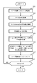
- FIG. 3 is a flowchart for explaining the image processing method according to the first embodiment.
- the image processing apparatus 1 removes fog in a moving image (video) will be described.
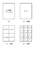
- FIG. 4 is a diagram illustrating regions for which histograms are to be generated by the 1-area divided enlargement unit 11, the 4-area divided enlargement unit 12, and the 9-area divided enlargement unit 13.
- FIG. 4A shows an area of one frame of a moving image that is an input image.
- FIG. 4B shows a region where a histogram is to be generated by the one-area divided enlargement unit 11 (first histogram generation unit 11a).
- FIG. 4C shows four regions (area 0, area 1, area 2, and area 3) that are to be generated by the 4-area division enlargement unit 12 (second histogram generation unit 12a).
- FIG. 4D shows nine areas (area 0, area 1, area 2, area 3, area 4, area 5) to be generated by the nine area division enlargement section 13 (third histogram generation section 13a). , Area 6, area 7, and area 8).
- the first histogram generation unit 11a generates a histogram in the input image area without dividing the input image area.
- the second histogram generation unit 12a divides the area of the input image into four areas, and generates a histogram in each area.
- the third histogram generation unit 13a divides the area of the input image into nine areas, and generates a histogram in each area. Note that the area illustrated in FIG. 4B is referred to as a zero-level area, each area illustrated in FIG. 4C is referred to as a one-level area, and the area illustrated in FIG. 4D is referred to as a two-level area.
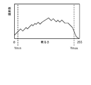
- FIG. 5 is a diagram illustrating an example of a histogram generated by the area division enlargement units 11, 12, and 13.
- the histogram shown in FIG. 5 is a histogram generated by the first histogram generation unit 11a in the input image area (FIG. 4B).
- the horizontal axis indicates the brightness (luminance level, illuminance, gradation) of the pixel. “0” on the horizontal axis is the darkest (black) and becomes brighter toward the right. “255” on the horizontal axis is the brightest (white).
- the vertical axis shows how many pixels have that brightness (that is, the vertical axis shows the number of pixels having the same brightness).
- the range calculation unit 11b sequentially adds the number of pixels (number of pixels) in the right direction on the horizontal axis from the brightness “0”. The range calculation unit 11b determines whether or not the number of added pixels exceeds the preset number of set value pixels. Then, the range calculation unit 11b sets the value immediately before the brightness value at which the added pixel number exceeds the set value pixel number as the minimum value Ymin. Y represents the pixel value (luminance) of an image without color (luminance 1 channel image). That is, Y corresponds to any one of R, G, and B. In addition, the range calculation unit 11b sequentially adds the number of pixels from the brightness “255” to the left in the horizontal axis. The range calculation unit 11b determines whether the number of added pixels exceeds the set value pixel number. Then, the range calculation unit 11b sets the value immediately before the brightness value at which the added pixel number exceeds the set value pixel number as the maximum value Ymax.
- the set value pixel number is a value for determining noise on the max side (255 side) and min side (0 side).
- the set value pixel number is, for example, about 1 to 3% of the number of all pixels in the region. In the present embodiment, the set value pixel number is 1% of the total number of pixels in the region.
- the range calculation unit 12b also determines whether or not the number of added pixels exceeds the set value pixel number for each of the four regions (area 0, area 1, area 2, and area 3), as in the range calculation unit 11b. And the minimum value Ymin and the maximum value Ymax are calculated. In addition, the range calculation unit 12b also includes a range calculation unit 11b for each of the nine regions (area 0, area 1, area 2, area 3, area 4, area 5, area 6, area 7, and area 8). Similarly, it is determined whether or not the number of added pixels exceeds the set number of pixels, and the minimum value Ymin and the maximum value Ymax are calculated.
- minval is set to 10.
- the dynamic range is not expanded in the region where the pixel value (luminance) hardly changes (region where the color is almost uniform). Thereby, it is possible to prevent an erroneous dynamic range expansion (malfunction).
- the range enlarging unit 11c based on the pixel value PixVal of each pixel of the input image region, the minimum value Ymin of the input image region, and the maximum value Ymax of the input image region, the target value of each pixel of the input image region Calculate (TargetValue). Specifically, the range expansion unit 11c calculates a target value (TargetValue) by substituting the pixel value PixVal, the minimum value Ymin, and the maximum value Ymax into the following equation (2).
- TargetValue (PixVal-Ymin) * 255 / (Ymax-Ymin) (2)
- the range enlargement unit 11c sets the table Table (R, G, B) of the area of the input image for the pixel value PixVal of 0 to 255 during blanking (period between the current frame and the next frame). create.
- the range enlarging unit 11c sets 0 for a pixel value less than or equal to the minimum value Ymin, and sets 255 for a pixel value greater than or equal to the maximum value Ymax.
- the range enlarging unit 11c uses the R, G, and B values as the minimum value Ymin and the maximum value Ymax when adjusting the white balance of the image.
- the range expansion unit 11c outputs the pixel value (that is, the target value (TargetValue)) of each pixel calculated by the above equation (2) to the area composition unit 14.
- the range expansion unit 12c also sets the pixel value of each pixel (that is, the target value (TargetValue)) for each of the four regions (area 0, area 1, area 2, area 3). calculate. Also in this case, the range expansion unit 12c calculates the target value using the minimum value Ymin and the maximum value Ymax corresponding to the presence / absence of white balance adjustment of the image.
- the range expansion unit 13c also includes a range expansion unit 11c for each of the nine regions (area 0, area 1, area 2, area 3, area 4, area 5, area 6, area 7, and area 8). Similarly, a pixel value of each pixel (that is, a target value (TargetValue)) is calculated. Also in this case, the range expansion unit 13c calculates the target value using the minimum value Ymin and the maximum value Ymax corresponding to the presence / absence of white balance adjustment of the image.
- the range enlarging unit 12c and the range enlarging unit 13c perform bilinear interpolation processing between regions in order to provide continuity of pixel values between the divided regions.
- pixel values luminance values
- the range enlarging unit 12c and the range enlarging unit 13c are respectively bi-linear interpolation based on the pixel value of the center position of each region divided by the second histogram generating unit 12a and the third histogram generating unit 13a. (TExpValue; pixel value after range expansion) is calculated.
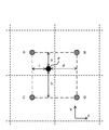
- FIG. 6 is a diagram for explaining bilinear interpolation processing.
- P indicates a pixel on which bilinear interpolation processing is performed.
- A, B, C, and D indicate pixels at the center positions of the four regions.
- A is a pixel at the center of area 0
- B is a pixel at the center of area 1
- C is a pixel at the center of area 2
- D is a pixel at the center of area 3. It becomes.
- A is a pixel at the center position of area 3
- B is a pixel at the center position of area 4
- C is a pixel at the center position of area 6
- D is a center position of area 7. It becomes a pixel.
- a is the distance in the y direction from the pixel P to the pixel A or B
- b is the distance in the y direction from the pixel P to the pixel C or D
- c is the distance in the x direction from the pixel P to the pixel A or C
- d is The distance in the x direction from the pixel P to the pixel B or D is shown.
- the range enlarging unit 12c and the range enlarging unit 13c substitute the pixel values of the pixels A, B, C, and D and the distances a, b, c, and d into the following formula (3). Pixel value after range expansion) is calculated.
- A, B, C, and D are values of table table subtraction of expanded values of pixel values (PixelValue) in each region.
- a counter (up counter (a)) is incremented by 0 until A (y) and then incremented by +1 until C (y), and (a + b) until A (y). Thereafter, a counter (down counter (b)) that counts down by ⁇ 1 to C (y) is prepared.
- the range enlarging unit 12c and the range enlarging unit 13c perform bilinear interpolation processing using these counters.
- the pixel value at the intermediate position can be obtained from the ratio of the pixel values at the center position of each region.
- the range expansion unit 12c outputs the pixel value (that is, the range expansion value (TexpValue)) of each pixel calculated by the above equation (3) to the area composition unit 14.
- the range expansion unit 13c outputs the pixel value (that is, the range expansion value (TexpValue)) of each pixel calculated by the above equation (3) to the area composition unit 14.
- the area composition unit 14 includes a pixel value A1 output from the 1-area division enlargement unit 11, a pixel value A4 output from the 4-area division enlargement unit 12, and a pixel value A9 output from the 9-area division enlargement unit 13. Enter.
- the area composition unit 14 multiplies the pixel value A1 by the coefficient ⁇ 1, multiplies the pixel value A4 by the coefficient ⁇ 4, and multiplies the pixel value A9 by the coefficient ⁇ 9.
- the area composition unit 14 adds (adds) the values obtained by multiplying the pixel values A1, A4, and A9 by the coefficients ⁇ 1, ⁇ 4, and ⁇ 9 to calculate a composite pixel value. That is, the area composition unit 14 calculates the composite pixel value by substituting the pixel values A1, A4, A9 and the coefficients ⁇ 1, ⁇ 4, ⁇ 9 into the following equation (4).
- ⁇ 1 + ⁇ 4 + ⁇ 9 1.0.
- the coefficient ⁇ 1 is 0.5
- the coefficient ⁇ 4 is 0.3
- the coefficient ⁇ 9 is 0.2.
- the atmospheric light pixel value calculation unit 20 generates a dark channel image based on the pixel value of each pixel of the fog image output from the dynamic range correction unit 10 (step S2). Specifically, the atmospheric light pixel value calculation unit 20 uses the smallest value (the minimum value among the R, G, and B channels) of each pixel as the dark channel value of each pixel. A dark channel image is generated as (r, g, b). Further, the atmospheric light pixel value calculation unit 20 acquires the minimum value of the dark channel value as the atmospheric light pixel value (atmosr, atmosg, atmosb) in the entire area of the input image (step S3).
- the transmittance calculation unit 30 uses the pixel value (r, g, b) and the atmospheric light pixel value (atmosr, atmosg, atmosb) of each pixel of the dark channel image from the atmospheric light pixel value calculation unit 20 to calculate each pixel.
- the transmittance (dtrans) is calculated. Specifically, the transmittance calculation unit 30 calculates the pixel value (r, g, b) and the atmospheric light pixel value (atmosr, atmosg, atmosb) of each pixel of the dark channel image in the following equation (5). By substituting, the transmittance (dtrans) for each pixel is calculated.
- the transmittance calculating unit 30 outputs a transmittance image including the transmittance of each pixel calculated as described above to the transmittance correcting unit 40 and the transmittance shaping unit 50.
- the transmittance correcting unit 40 corrects the transmittance image (initial transmittance image) output from the transmittance calculating unit 30 (step S5).
- the transmittance correction process executed by the transmittance correction unit 40 will be described with reference to FIG.
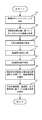
- FIG. 7 is a flowchart showing the transmittance correction processing by the transmittance correction unit.
- the transmittance correction unit 40 initializes the number of loops (nloop) (step S11). That is, the transmittance correction unit 40 substitutes an initial value 0 for nloop.
- the transmittance correction unit 40 forms a 3 ⁇ 3 pixel region (3 ⁇ 3 window) in the region of the transmittance image (step S12).
- the transmittance correction unit 40 acquires an average value of the transmittance in each 3 ⁇ 3 pixel region (3 ⁇ 3 window) (step S13).
- the transmittance correction unit 40 binarizes each pixel with an average value in each 3 ⁇ 3 pixel region (step S14).
- the transmittance correction unit 40 divides each pixel in a region of 3 ⁇ 3 pixels into a pixel having a transmittance higher than the average value (High pixel) and a pixel having a low transmittance (Low pixel).
- the transmittance correction unit 40 sets the High pixel to “1” and the Low pixel to “0”. Further, the transmittance correction unit 40 acquires the average value (have) of the transmittance of the High pixel, and acquires the average value (love) of the transmittance of the Low pixel (Step S15).
- the transmittance correction unit 40 counts the number of high pixels (hcnt) and the number of low pixels (lcnt) in each 3 ⁇ 3 pixel region. Further, the transmittance correction unit 40 calculates an average value (ave) of the transmittance of the entire transmittance image. And the transmittance
- the transmittance correction unit 40 sets the transmittance (Ttrans) to the average value (lav) of the Low pixels. Further, if the number of high pixels (hcnt) is 7 or more (hcnt ⁇ 7), the transmittance correction unit 40 sets the transmittance (Ttrans) to the average value (have) of the high pixels. Further, the transmittance correction unit 40, when (have-lav) * 255> 20 and abs (ave-Ctrans) ⁇ 5, the transmittance (Ttrans) is transmitted by the central pixel in the 3 ⁇ 3 pixel region. The rate is Ctrans.
- the transmittance correction unit 40 sets the transmittance (Ttrans) to the average value (have) of High pixels if Ctrans> (lav + have) /2.0. In other cases, the transmittance correction unit 40 sets the transmittance (Ttrans) to the average value (lav) of the Low pixels.
- the transmittance correction unit 40 outputs the transmittance (Ttrans) determined as shown in FIG. 7 to the transmittance shaping unit 50.
- the transmittance shaping unit 50 transmits the transmittance (dtrans) of each pixel output from the transmittance calculation unit 30 and the transmittance (Ttrans) of each pixel output from the transmittance correction unit 40. Enter. Then, the transmittance shaping unit 50 calculates the transmittance (Mtrans) after shaping of each pixel by substituting those transmittances (dtrans, Ttrans) into the following equation (6) (step S6). That is, the transmittance shaping unit 50 shapes the transmittance image using the transmittance before correction (dtrans) and the transmittance after correction (Ttrans). In equation (6), sqrt () means obtaining the square root in ().
- the transmittance shaping unit 50 outputs the shaped transmittance (Mtrans) to the fog removal image generation unit 60.
- the fog removal image generation unit 60 transmits the atmospheric light pixel values (atmosr, atmosg, and atmosb) output from the atmospheric light pixel value calculation unit 20 and the transmission of each pixel after shaping output from the transmittance shaping unit 50.
- a fog removal process for removing fog in the image is executed (step S7). ).
- the fog removal image generation unit 60 calculates the atmospheric light pixel values (atmosr, atmosg, atmosb), the transmittance (Mtrans), and the pixel values (Formulas (7-1) to (7-3)) By substituting r, g, b), the pixel values (newR, newG, newB) of each pixel from which the fog in the image is removed are calculated.
- the transmittance correction unit 40 executes the processing as illustrated in FIG. 7, the processing by the transmittance shaping unit 50 may be omitted.
- the transmittance correction unit 40 outputs the transmittance (Ttrans) to the fog removal image generation unit 60, and the fog removal image generation unit 60 outputs the atmospheric light pixel value (from the atmospheric light pixel value calculation unit 20).
- the transmittance (Ttrans) of each pixel output from the transmittance correction unit 40 outputs the pixel value (r, g, b) of each pixel of the fog image output from the dynamic range correction unit 10
- a fog removal process for removing fog in the image is executed.
- the dark channel image generation unit 20 that generates a dark channel image based on the input image, the dark channel image generated by the dark channel image generation unit 20, and the atmospheric light pixel value.
- the transmittance image generating unit 30 that generates a transmittance image based on the above, the transmittance correcting unit 40 that corrects the transmittance image generated by the transmittance image generating unit 30, and the transmittance correcting unit 40
- a fog removal image generation unit 60 that removes fog in the input image based on the transmittance image, the atmospheric light pixel value, and the input image; According to such a configuration, fog in the image can be removed at high speed with a low processing load.
- the transmittance correction unit 40 divides the transmittance image into predetermined regions (for example, 3 ⁇ 3 pixel regions), and the transmittance is corrected by an average value of 2 for each pixel in each divided predetermined region. Quantization is performed, and the transmittance of each pixel in each predetermined region is selected based on the number of binarized values in each predetermined region and the average value of the transmittance of each value in each predetermined region. . According to such a configuration, it is possible to make the transmittance uniform without applying a processing burden compared to soft matting.
- the transmittance of each pixel of the transmittance image corrected by the transmittance correcting unit 40 is multiplied by the transmittance of each pixel of the transmittance image generated by the transmittance image generating unit 30.
- a transmittance shaping unit 50 that shapes the transmittance image by performing a square root operation of the multiplied value, and the fog removal image generation unit 60 includes the transmittance image and the atmospheric light pixel value shaped by the transmittance shaping unit 50.
- the fog in the input image is removed based on the input image. According to such a configuration, it is possible to suppress the occurrence of halos when the transmittance image is corrected by the transmittance correcting unit 40.
- the range correction unit 10 that expands the range of the input image
- the dark channel image generation unit 20 generates a dark channel image based on the image whose range is expanded by the range correction unit 10.
- the fog removal image generation unit 60 removes fog in the image based on the transmittance image corrected by the transmittance correction unit 40, the atmospheric light pixel value, and the image whose range is expanded by the range correction unit 10. According to such a configuration, it is possible to reduce the fog in the image by expanding the dynamic range of the input image.
- the range correction unit 10 divides the input image into a plurality of regions and expands the ranges of the plurality of divided regions.
- the first range correction unit 11 expands the range of the input image region.
- a second range correction unit 12 that combines the image whose range is expanded by the first range correction unit 11 and the image whose range is expanded by the second range correction unit 12. According to such a configuration, it is possible to combine fogged images in a plurality of hierarchies and more reliably realize fog reduction.
- the synthesizing unit 14 multiplies the image whose range has been expanded by the first range correction unit 11 by the first coefficient, and the second range of the image whose range has been expanded by the second range correction unit 12. Multiply the coefficients and add the images. According to such a configuration, it is possible to combine images after weighting each image.
- the second range correction unit 12 since the second range correction unit 12 performs the interpolation process on the image whose range has been expanded, the continuity of the pixel values between the divided regions can be provided.
- the transmittance correction unit 40 executes the transmittance correction processing as shown in FIG. 7, but in the second embodiment, the transmittance morphology processing unit 40A performs the transmittance correction processing ( (Expansion process, morphological process).
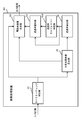
- FIG. 8 is a block diagram showing the configuration of the image processing apparatus according to the second embodiment.
- An image processing apparatus 1A illustrated in FIG. 8 includes a transmittance morphology processing unit 40A instead of the transmittance correction unit 40 in the image processing apparatus 1 illustrated in FIG.
- Other configurations are the same as those described with reference to FIG.
- the transmittance morphology processing unit 40A performs a morphology process on the transmittance image output from the transmittance calculating unit 30. Specifically, the transmittance morphology processing unit 40A forms a 3 ⁇ 3 pixel region (3 ⁇ 3 window) in the region of the transmittance image. Then, the transmittance morphology processing unit 40A obtains an average value of the transmittance in each 3 ⁇ 3 pixel region (3 ⁇ 3 window). Further, the transmittance morphology processing unit 40A binarizes each pixel by an average value in each 3 ⁇ 3 pixel region.
- the transmittance morphology processing unit 40A determines the transmittance of the target pixel if there is a high pixel even in one of the eight pixels in the vicinity of the target pixel (center pixel) in each 3 ⁇ 3 pixel region. Let it be the average value (have) of the transmittance of High pixels in the 3 ⁇ 3 pixel region. Such a process is called a morphological process.
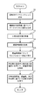
- FIG. 9 is a flowchart for explaining the image processing method according to the second embodiment.
- the processes other than step S5A are the same as the processes shown in FIG.
- step S5A the transmittance morphology processing unit 40A performs a morphology process on the transmittance image.
- the transmittance morphology processing unit 40A transmits the target pixel if there is a high pixel in one of the eight pixels in the vicinity of the target pixel (center pixel) in each 3 ⁇ 3 pixel region. Let the rate be the average value (have) of the transmittance of High pixels in the 3 ⁇ 3 pixel area.
- the transmittance morphology processing unit 40A executes the morphology processing (simple multi-value expansion processing), processing by the transmittance shaping unit 50 is required.
- the transmittance correction unit 40 performs a morphological process on the transmittance image. Even with such a configuration, it is possible to make the transmittance uniform without imposing a processing burden.
- the fluctuation absorbing device may be not only the audio IP conversion device 2A and the audio IP conversion device 6A, but also the audio IP conversion device 1B and the audio IP conversion device 5B. That is, the audio IP conversion device 1B may have the same configuration as the audio IP conversion device 2A, and the audio IP conversion device 5B may have the same configuration as the audio IP conversion device 6A.
- the dynamic range correction unit 10 performs image range expansion on three layers, but may be configured to perform image range expansion on two or more layers.
- the transmittance correction unit 40 divides the transmittance image into 3 ⁇ 3 pixel regions (see step S12), but the number of different pixels is not limited to 3 ⁇ 3 pixels. It may be a region. Moreover, although the bilinear interpolation process was used for the interpolation process, other interpolation processes may be used.
- Dynamic Range Correction Unit 11 1 area division enlargement part (first range correction part) 12 4 area division enlargement part (second range correction part) 13 9 Area division enlargement part (second range correction part) 14 Area composition part (composition part) 20 Atmospheric light pixel value calculation unit (dark channel image generation unit) 30 Transmittance calculation unit (Transmittance image generation unit) 40 Transmittance Correction Unit 40A Transmittance Morphology Processing Unit 50 Transmittance Shaping Unit 60 Fog Removal Image Generation Unit
Landscapes
- Engineering & Computer Science (AREA)
- Physics & Mathematics (AREA)
- General Physics & Mathematics (AREA)
- Theoretical Computer Science (AREA)
- Multimedia (AREA)
- Signal Processing (AREA)
- Image Processing (AREA)
- Picture Signal Circuits (AREA)
- Facsimile Image Signal Circuits (AREA)
Priority Applications (2)
| Application Number | Priority Date | Filing Date | Title |
|---|---|---|---|
| CN201480008175.5A CN104981840B (zh) | 2013-11-25 | 2014-01-15 | 图像处理装置以及图像处理方法 |
| US14/654,535 US9639916B2 (en) | 2013-11-25 | 2014-01-15 | Image processing device, and image processing method |
Applications Claiming Priority (2)
| Application Number | Priority Date | Filing Date | Title |
|---|---|---|---|
| JP2013242835A JP6182056B2 (ja) | 2013-11-25 | 2013-11-25 | 画像処理装置 |
| JP2013-242835 | 2013-11-25 |
Publications (1)
| Publication Number | Publication Date |
|---|---|
| WO2015075952A1 true WO2015075952A1 (ja) | 2015-05-28 |
Family
ID=53179232
Family Applications (1)
| Application Number | Title | Priority Date | Filing Date |
|---|---|---|---|
| PCT/JP2014/050489 Ceased WO2015075952A1 (ja) | 2013-11-25 | 2014-01-15 | 画像処理装置、画像処理方法、及び制御プログラム |
Country Status (5)
| Country | Link |
|---|---|
| US (1) | US9639916B2 (enExample) |
| JP (1) | JP6182056B2 (enExample) |
| CN (1) | CN104981840B (enExample) |
| TW (1) | TW201520977A (enExample) |
| WO (1) | WO2015075952A1 (enExample) |
Cited By (4)
| Publication number | Priority date | Publication date | Assignee | Title |
|---|---|---|---|---|
| CN106327439A (zh) * | 2016-08-16 | 2017-01-11 | 华侨大学 | 一种快速雾霾天图像清晰化方法 |
| CN108140237A (zh) * | 2015-09-29 | 2018-06-08 | 富士胶片株式会社 | 图像处理装置以及图像处理方法 |
| CN113129219A (zh) * | 2019-12-30 | 2021-07-16 | 比亚迪股份有限公司 | 图像处理方法、装置及设备 |
| CN113344796A (zh) * | 2020-02-18 | 2021-09-03 | 腾讯科技(深圳)有限公司 | 一种图像处理方法、装置、设备及存储介质 |
Families Citing this family (6)
| Publication number | Priority date | Publication date | Assignee | Title |
|---|---|---|---|---|
| KR102096356B1 (ko) | 2018-09-07 | 2020-04-02 | 고려대학교 산학협력단 | 다크 채널 기반의 단일 영상 안개 제거 방법, 장치 및 상기 방법을 수행하기 위한 기록 매체 |
| CN110288541A (zh) * | 2019-06-06 | 2019-09-27 | 武汉易科空间信息技术股份有限公司 | 航空影像高精度处理方法及系统 |
| JP7263149B2 (ja) * | 2019-06-26 | 2023-04-24 | キヤノン株式会社 | 画像処理装置、画像処理方法、およびプログラム |
| CN110660026B (zh) * | 2019-08-08 | 2023-04-18 | 西安电子科技大学 | 一种基于Retinex理论和高饱和度先验的图像去雾方法 |
| CN111325688B (zh) * | 2020-02-18 | 2023-05-05 | 西安汇智信息科技有限公司 | 融合形态学聚类优化大气光的无人机图像去雾方法 |
| US12347079B2 (en) * | 2022-09-20 | 2025-07-01 | Nanjing University Of Posts And Telecommunications | Method for image defogging based on dark channel prior |
Citations (6)
| Publication number | Priority date | Publication date | Assignee | Title |
|---|---|---|---|---|
| JP2011003048A (ja) * | 2009-06-19 | 2011-01-06 | Casio Computer Co Ltd | 画像処理装置、及び画像処理プログラム |
| US20110188775A1 (en) * | 2010-02-01 | 2011-08-04 | Microsoft Corporation | Single Image Haze Removal Using Dark Channel Priors |
| JP2012221237A (ja) * | 2011-04-08 | 2012-11-12 | Olympus Corp | 霞除去画像処理装置、霞除去画像処理方法及び霞除去画像処理プログラム |
| WO2013018101A1 (en) * | 2011-08-03 | 2013-02-07 | Indian Institute Of Technology, Kharagpur | Method and system for removal of fog, mist or haze from images and videos |
| WO2013029337A1 (en) * | 2011-08-30 | 2013-03-07 | Fujitsu Limited | Image defogging method and system |
| JP2013058202A (ja) * | 2011-09-08 | 2013-03-28 | Fujitsu Ltd | 画像の霧除去方法及びシステム |
Family Cites Families (1)
| Publication number | Priority date | Publication date | Assignee | Title |
|---|---|---|---|---|
| US8396324B2 (en) * | 2008-08-18 | 2013-03-12 | Samsung Techwin Co., Ltd. | Image processing method and apparatus for correcting distortion caused by air particles as in fog |
-
2013
- 2013-11-25 JP JP2013242835A patent/JP6182056B2/ja active Active
-
2014
- 2014-01-15 US US14/654,535 patent/US9639916B2/en not_active Expired - Fee Related
- 2014-01-15 WO PCT/JP2014/050489 patent/WO2015075952A1/ja not_active Ceased
- 2014-01-15 CN CN201480008175.5A patent/CN104981840B/zh not_active Expired - Fee Related
- 2014-01-17 TW TW103101738A patent/TW201520977A/zh not_active IP Right Cessation
Patent Citations (6)
| Publication number | Priority date | Publication date | Assignee | Title |
|---|---|---|---|---|
| JP2011003048A (ja) * | 2009-06-19 | 2011-01-06 | Casio Computer Co Ltd | 画像処理装置、及び画像処理プログラム |
| US20110188775A1 (en) * | 2010-02-01 | 2011-08-04 | Microsoft Corporation | Single Image Haze Removal Using Dark Channel Priors |
| JP2012221237A (ja) * | 2011-04-08 | 2012-11-12 | Olympus Corp | 霞除去画像処理装置、霞除去画像処理方法及び霞除去画像処理プログラム |
| WO2013018101A1 (en) * | 2011-08-03 | 2013-02-07 | Indian Institute Of Technology, Kharagpur | Method and system for removal of fog, mist or haze from images and videos |
| WO2013029337A1 (en) * | 2011-08-30 | 2013-03-07 | Fujitsu Limited | Image defogging method and system |
| JP2013058202A (ja) * | 2011-09-08 | 2013-03-28 | Fujitsu Ltd | 画像の霧除去方法及びシステム |
Non-Patent Citations (2)
| Title |
|---|
| AKIRA MIZUNO ET AL.: "Local Adaptive High-Speed Single Image Dehazing", ITE TECHNICAL REPORT, vol. 36, no. 20, 21 May 2012 (2012-05-21), pages 9 - 12 * |
| SHIN'ICHIRO HIROOKA ET AL.: "Real-time Image Visibility Enhancement Technology under Bad Weather Condition for Video Cameras", IPSJ SIG NOTES CONSUMER DEVICES AND SYSTEMS(CDS, vol. 2013 -CD, no. 1, 5 September 2013 (2013-09-05), pages 1 - 6, Retrieved from the Internet <URL:https://ipsj.ixsq.nii.ac.jp/ej/?action=pages_view_main&active_action=repository_view_main_item_detail&item_id=95137&item_no=1&page_id=13&block_id=8> * |
Cited By (7)
| Publication number | Priority date | Publication date | Assignee | Title |
|---|---|---|---|---|
| CN108140237A (zh) * | 2015-09-29 | 2018-06-08 | 富士胶片株式会社 | 图像处理装置以及图像处理方法 |
| CN108140237B (zh) * | 2015-09-29 | 2021-11-19 | 富士胶片株式会社 | 图像处理装置以及图像处理方法 |
| CN106327439A (zh) * | 2016-08-16 | 2017-01-11 | 华侨大学 | 一种快速雾霾天图像清晰化方法 |
| CN106327439B (zh) * | 2016-08-16 | 2019-01-01 | 华侨大学 | 一种快速雾霾天图像清晰化方法 |
| CN113129219A (zh) * | 2019-12-30 | 2021-07-16 | 比亚迪股份有限公司 | 图像处理方法、装置及设备 |
| CN113344796A (zh) * | 2020-02-18 | 2021-09-03 | 腾讯科技(深圳)有限公司 | 一种图像处理方法、装置、设备及存储介质 |
| CN113344796B (zh) * | 2020-02-18 | 2025-10-31 | 腾讯科技(深圳)有限公司 | 一种图像处理方法、装置、设备及存储介质 |
Also Published As
| Publication number | Publication date |
|---|---|
| US20150332437A1 (en) | 2015-11-19 |
| CN104981840B (zh) | 2017-07-14 |
| JP2015103001A (ja) | 2015-06-04 |
| TW201520977A (zh) | 2015-06-01 |
| CN104981840A (zh) | 2015-10-14 |
| JP6182056B2 (ja) | 2017-08-16 |
| US9639916B2 (en) | 2017-05-02 |
| TWI567692B (enExample) | 2017-01-21 |
Similar Documents
| Publication | Publication Date | Title |
|---|---|---|
| JP6182056B2 (ja) | 画像処理装置 | |
| EP2833317B1 (en) | Image display device and/or method therefor | |
| JP5392560B2 (ja) | 画像処理装置および画像処理方法 | |
| JP5669513B2 (ja) | 画像処理装置、画像処理プログラム、及び、画像処理方法 | |
| TW201410005A (zh) | 影像處理方法以及影像處理裝置 | |
| JP4290193B2 (ja) | 画像処理装置 | |
| JP6485068B2 (ja) | 画像処理方法および画像処理装置 | |
| CN104881845A (zh) | 用于处理图像的方法和设备 | |
| JPWO2013054454A1 (ja) | 映像信号処理装置 | |
| JP5410378B2 (ja) | 映像信号補正装置および映像信号補正プログラム | |
| JP6541326B2 (ja) | 画像処理装置及びその制御方法、画像表示装置、コンピュータプログラム | |
| JP2013106151A (ja) | 画像処理装置及び画像処理方法 | |
| JP4308280B2 (ja) | 階調補正装置 | |
| CN101567965A (zh) | 图像处理装置 | |
| JP2013162247A (ja) | 画像処理装置およびその制御方法 | |
| US20150339807A1 (en) | Video contrast enhancement with sub-segments | |
| JP6575742B2 (ja) | 画像処理方法および画像処理装置 | |
| JP6504500B2 (ja) | ビデオ画像強調方法 | |
| CN101742177B (zh) | 影像滤波电路及应用其的影像处理电路及影像处理方法 | |
| JP2016001827A (ja) | 画像処理装置、画像処理方法及びプログラム | |
| JP2011022779A (ja) | 画像補正装置、画像補正方法及びプログラム | |
| JP6201933B2 (ja) | 映像信号処理装置、映像信号処理方法、映像信号処理プログラム | |
| JP2019053590A (ja) | 画像処理装置、画像処理方法、及びプログラム | |
| JP2017146766A (ja) | 画像処理装置、画像処理方法、画像処理プログラム | |
| JP2006041946A (ja) | 画像補正装置及び撮像装置 |
Legal Events
| Date | Code | Title | Description |
|---|---|---|---|
| WWE | Wipo information: entry into national phase |
Ref document number: 14654535 Country of ref document: US |
|
| 121 | Ep: the epo has been informed by wipo that ep was designated in this application |
Ref document number: 14863385 Country of ref document: EP Kind code of ref document: A1 |
|
| NENP | Non-entry into the national phase |
Ref country code: DE |
|
| 122 | Ep: pct application non-entry in european phase |
Ref document number: 14863385 Country of ref document: EP Kind code of ref document: A1 |