WO2015072167A1 - 撮像装置、撮像システム、撮像方法、及び撮像プログラム - Google Patents
撮像装置、撮像システム、撮像方法、及び撮像プログラム Download PDFInfo
- Publication number
- WO2015072167A1 WO2015072167A1 PCT/JP2014/064503 JP2014064503W WO2015072167A1 WO 2015072167 A1 WO2015072167 A1 WO 2015072167A1 JP 2014064503 W JP2014064503 W JP 2014064503W WO 2015072167 A1 WO2015072167 A1 WO 2015072167A1
- Authority
- WO
- WIPO (PCT)
- Prior art keywords
- imaging
- imaging device
- unit
- image
- communication
- Prior art date
- Legal status (The legal status is an assumption and is not a legal conclusion. Google has not performed a legal analysis and makes no representation as to the accuracy of the status listed.)
- Ceased
Links
Images











Classifications
-
- H—ELECTRICITY
- H04—ELECTRIC COMMUNICATION TECHNIQUE
- H04N—PICTORIAL COMMUNICATION, e.g. TELEVISION
- H04N1/00—Scanning, transmission or reproduction of documents or the like, e.g. facsimile transmission; Details thereof
- H04N1/00127—Connection or combination of a still picture apparatus with another apparatus, e.g. for storage, processing or transmission of still picture signals or of information associated with a still picture
- H04N1/00132—Connection or combination of a still picture apparatus with another apparatus, e.g. for storage, processing or transmission of still picture signals or of information associated with a still picture in a digital photofinishing system, i.e. a system where digital photographic images undergo typical photofinishing processing, e.g. printing ordering
- H04N1/00183—Photography assistance, e.g. displaying suggestions to the user
-
- H—ELECTRICITY
- H04—ELECTRIC COMMUNICATION TECHNIQUE
- H04N—PICTORIAL COMMUNICATION, e.g. TELEVISION
- H04N23/00—Cameras or camera modules comprising electronic image sensors; Control thereof
- H04N23/50—Constructional details
- H04N23/53—Constructional details of electronic viewfinders, e.g. rotatable or detachable
- H04N23/531—Constructional details of electronic viewfinders, e.g. rotatable or detachable being rotatable or detachable
-
- H—ELECTRICITY
- H04—ELECTRIC COMMUNICATION TECHNIQUE
- H04N—PICTORIAL COMMUNICATION, e.g. TELEVISION
- H04N23/00—Cameras or camera modules comprising electronic image sensors; Control thereof
- H04N23/60—Control of cameras or camera modules
- H04N23/62—Control of parameters via user interfaces
-
- H—ELECTRICITY
- H04—ELECTRIC COMMUNICATION TECHNIQUE
- H04N—PICTORIAL COMMUNICATION, e.g. TELEVISION
- H04N23/00—Cameras or camera modules comprising electronic image sensors; Control thereof
- H04N23/60—Control of cameras or camera modules
- H04N23/63—Control of cameras or camera modules by using electronic viewfinders
- H04N23/633—Control of cameras or camera modules by using electronic viewfinders for displaying additional information relating to control or operation of the camera
-
- H—ELECTRICITY
- H04—ELECTRIC COMMUNICATION TECHNIQUE
- H04N—PICTORIAL COMMUNICATION, e.g. TELEVISION
- H04N23/00—Cameras or camera modules comprising electronic image sensors; Control thereof
- H04N23/60—Control of cameras or camera modules
- H04N23/64—Computer-aided capture of images, e.g. transfer from script file into camera, check of taken image quality, advice or proposal for image composition or decision on when to take image
-
- H—ELECTRICITY
- H04—ELECTRIC COMMUNICATION TECHNIQUE
- H04N—PICTORIAL COMMUNICATION, e.g. TELEVISION
- H04N5/00—Details of television systems
- H04N5/44—Receiver circuitry for the reception of television signals according to analogue transmission standards
-
- G—PHYSICS
- G03—PHOTOGRAPHY; CINEMATOGRAPHY; ANALOGOUS TECHNIQUES USING WAVES OTHER THAN OPTICAL WAVES; ELECTROGRAPHY; HOLOGRAPHY
- G03B—APPARATUS OR ARRANGEMENTS FOR TAKING PHOTOGRAPHS OR FOR PROJECTING OR VIEWING THEM; APPARATUS OR ARRANGEMENTS EMPLOYING ANALOGOUS TECHNIQUES USING WAVES OTHER THAN OPTICAL WAVES; ACCESSORIES THEREFOR
- G03B17/00—Details of cameras or camera bodies; Accessories therefor
- G03B17/18—Signals indicating condition of a camera member or suitability of light
Definitions
- the present invention relates to an imaging apparatus for imaging a subject, an imaging system including the imaging apparatus, an imaging method performed by the imaging apparatus, and an imaging program executed by the imaging apparatus.
- Patent Document 1 A technique for sequentially transmitting to a communication device is known (see, for example, Patent Document 1).
- the technology described in Patent Document 1 is a technology for remotely operating an imaging device by a communication device.
- the communication device sequentially receives the image data transmitted from the imaging device, and sequentially displays live view images corresponding to the image data on the display unit.
- the user of the communication device performs a predetermined operation on the communication device at a timing when the imaging device wants to execute the recording of the image data while confirming the live view image displayed on the display unit of the communication device.
- a recording request for image data is transmitted from the communication device to the imaging device, and the imaging device performs an imaging operation (recording operation for image data) after receiving the recording request.
- the user of the communication device may want to advise that shooting is performed at a nearby shooting spot while confirming the live view image displayed on the display unit of the communication device.
- the other communication means such as a mobile phone to give the above-mentioned advice. For this reason, there is a problem that the convenience can not be improved.
- the present invention has been made in view of the above, and it is an object of the present invention to provide an imaging device, an imaging system, an imaging method, and an imaging program capable of improving convenience.
- an imaging device is an imaging device for imaging a subject, the imaging unit for imaging the subject to generate image data, and displaying an image (1)
- the image data generated by the imaging unit is transmitted to the communication device via the display unit, a first communication unit that communicably connects information with an external communication device, and the first communication unit.
- a first communication control unit that receives operation instruction information related to an operation instruction to the user of the imaging device from the communication device, and the operation instruction information when the operation instruction information is received via the first communication unit.
- a pseudo image generation unit that generates a pseudo image that simulates the user's operation of the imaging device according to the operation instruction based on the image; and the pseudo image generated by the pseudo image generation unit according to the first table
- the operation instruction information includes angle change instruction information on an angle change instruction for instructing a change of the camera angle of the imaging device with respect to the subject
- the pseudo image generation unit The pseudo image for causing the user of the imaging device to change the camera angle is generated based on the angle change instruction information.
- the subject is a user of the imaging device
- the pseudo image generation unit is based on the angle change instruction information that the user of the imaging device is the imaging device. It is characterized in that the pseudo image is generated which artificially expresses the state set to the camera angle in accordance with the angle change instruction.
- a position acquisition unit that acquires position information regarding the position of the imaging device, and a first direction that acquires first orientation information regarding an orientation imaged by the imaging device.
- An acquisition unit the operation instruction information includes imaging instruction information related to an imaging instruction instructing imaging at a specific place
- the pseudo image generation unit transmits the imaging instruction information via the first communication unit. Based on the position information and the first azimuth information acquired by the position acquisition unit and the first azimuth acquisition unit upon reception, and the photographing instruction information, the photographing instruction information of the user of the imaging apparatus Generating the pseudo image for guiding to a specific place based on.
- the pseudo image generation unit is configured to calculate a distance related to a distance from a current position of the imaging device to the specific place based on the position information and the photographing instruction information. An image is generated, and the first display control unit displays the pseudo image and the distance image on the first display unit.
- the first communication control unit transmits the position information acquired by the position acquisition unit to the communication device via the first communication unit. It is characterized by
- the operation instruction information includes imaging instruction information regarding an imaging instruction instructing imaging at a specific place
- the imaging device is a position regarding the position of the imaging device.
- the current position of the imaging device is the imaging instruction
- a position determination unit that determines whether or not the specific position based on the information is located within a predetermined distance range
- the pseudo image generation unit uses the position determination unit to determine the current position of the imaging device.
- the imaging device further includes a first operation receiving unit for receiving a first operation for instructing a photographing condition, wherein the first communication control unit When an operation is received, imaging condition information related to the imaging condition is transmitted to the communication device via the first communication unit.
- the subject is a user of the imaging device
- the first display control unit is configured such that the user of the imaging device is imaged by the imaging unit.
- An image corresponding to the generated image data and the pseudo image are displayed on the first display unit, and the user of the imaging device is urged to perform an operation according to the operation instruction based on the operation instruction information.
- an imaging system includes the above-described imaging device and a communication device for communicably connecting information with the imaging device, and the communication device relates to an operation instruction for a user of the imaging device.
- a second operation receiving unit that receives a second operation, a second communication unit that communicably connects information with the imaging device, and the second operation receiving unit receives the second operation;
- a second communication control unit that transmits operation instruction information related to the operation instruction to the imaging device via a second communication unit.
- An imaging system is an imaging system including an imaging device for imaging a subject and a communication device connected so as to be able to transmit and receive information between the imaging device, wherein the communication device is the imaging device.
- the communication device is the imaging device.
- a second communication control unit for transmitting to the imaging device a pseudo image representing the image in a pseudo manner, a second display unit for displaying the image, and an image corresponding to the image data received via the second communication unit
- a pseudo image generation unit that generates the pseudo image according to the operation instruction, and the operation instruction is an angle change instruction to change the camera angle of the imaging device with respect to the subject of the imaging device. And the pseudo image generation unit generates the pseudo image for causing the user of the imaging device to change the camera angle when the second operation reception unit receives the second operation related to the angle change instruction.
- the imaging device captures an image of the subject and generates an image data, a first display unit displaying an image, a first communication unit communicably connecting information with the communication device, and First communication control that transmits the image data generated by the imaging unit to the communication device via the first communication unit, and receives the pseudo image from the communication device
- First communication control that transmits the image data generated by the imaging unit to the communication device via the first communication unit, and receives the pseudo image from the communication device
- First communication control that transmits the image data generated by the imaging unit to the communication device via the first communication unit, and receives the pseudo image from the communication device
- a first display control unit for displaying the pseudo image on the first display unit.
- the communication device may include a second display unit for displaying an image, and an image corresponding to the image data received via the second communication unit.
- An imaging method is an imaging method performed by an imaging apparatus for imaging a subject, the imaging step for imaging the subject to generate image data, and transmitting the image data to an external communication device.
- a display step of displaying the pseudo image wherein the operation instruction information relates to an angle change instruction to change the camera angle of the imaging device with respect to the subject.
- Angle change instruction information is included, and the pseudo image generation step includes the angle change instruction information. Zui it, and generates the pseudo image for changing the camera angle to the user of the imaging device.
- An imaging program according to the present invention is characterized in that the imaging apparatus executes the above-described imaging method.
- the imaging device when receiving operation instruction information from an external communication device, generates a pseudo image that simulates the operation of the user of the imaging device according to the operation instruction based on the operation instruction information Do. Then, the imaging device displays the pseudo image. Therefore, the user of the imaging device can recognize the operation instruction instructed by the user of the communication device from the pseudo image displayed on the imaging device, and perform the operation according to the operation instruction. That is, the user of the communication device can give various advices to the user of the imaging device without using other communication means such as a mobile phone. Therefore, according to the imaging device of the present invention, it is possible to improve the convenience.
- the imaging system according to the present invention includes the above-described imaging device, the same effects as those of the above-described imaging device can be obtained.
- the imaging method according to the present invention is an imaging method performed by the above-described imaging device, the same effects as those of the above-described imaging device can be obtained.
- an imaging program according to the present invention is a program executed by the above-described imaging device, the same effect as that of the above-described imaging device can be obtained.
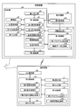
- FIG. 1 is a block diagram showing a configuration of an imaging system according to Embodiment 1 of the present invention.
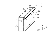
- FIG. 2 is a perspective view of a state in which the first display unit in the imaging apparatus shown in FIG. 1 is positioned at a reference position, as viewed from the side facing the user of the imaging apparatus.
- FIG. 3 is a perspective view of a state in which the first display unit in the imaging apparatus shown in FIG. 1 is positioned at the self shooting position as viewed from the subject side of the imaging apparatus.
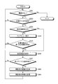
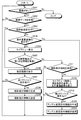
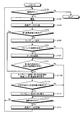
- FIG. 4 is a flowchart showing the operation of the imaging apparatus shown in FIGS. 1 to 3.
- FIG. 5 is a flow chart showing the operation of the communication device shown in FIG. FIG.
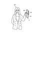
- FIG. 6 is a view schematically showing the posture of the user of the imaging apparatus at the time of operation of the imaging system shown in FIGS. 4 and 5.
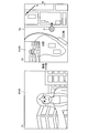
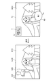
- FIG. 7 is a view showing an example of an image displayed on the imaging device and the communication device when the user of the imaging device performs an advice request operation during the operation of the imaging system shown in FIGS. 4 and 5.
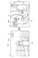
- FIG. 8 is a view showing an example of a first advice operation performed by the user of the communication device at the time of operation of the imaging system shown in FIGS. 4 and 5 and a first superimposed image displayed on the imaging apparatus.
- FIG. 9 is a view showing an example of a first advice operation performed by the user of the communication device at the time of operation of the imaging system shown in FIGS. 4 and 5 and a first superimposed image displayed on the imaging apparatus.
- FIG. 10 is a view showing an example of a first advice operation performed by the user of the communication device at the time of operation of the imaging system shown in FIGS. 4 and 5 and a first superimposed image displayed on the imaging apparatus.
- FIG. 11 is a view showing an example of a first advice operation performed by the user of the communication device at the time of operation of the imaging system shown in FIGS. 4 and 5 and a first superimposed image displayed on the imaging apparatus.
- FIG. 12 is a view showing an example of a first advice operation performed by the user of the communication device at the time of operation of the imaging system shown in FIGS. 4 and 5 and a first superimposed image displayed on the imaging apparatus.
- FIG. 11 is a view showing an example of a first advice operation performed by the user of the communication device at the time of operation of the imaging system shown in FIGS. 4 and 5 and a first superimposed image displayed on the imaging apparatus.
- FIG. 12 is a view showing an example of a first advice operation performed by the user of the communication device at the time of operation of
- FIG. 13 is a view showing an example of a first advice operation performed by the user of the communication device at the time of operation of the imaging system shown in FIGS. 4 and 5 and a first superimposed image displayed on the imaging apparatus.
- FIG. 14 is a flowchart showing an operation of the imaging device according to Embodiment 2 of the present invention.
- FIG. 15 is a flowchart showing an operation of the communication device according to Embodiment 2 of the present invention.
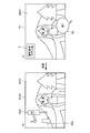
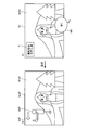
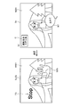
- FIG. 16 is a view showing an example of a second advice operation performed by the user of the communication device at the time of operation of the imaging system shown in FIGS. 14 and 15 and a second superimposed image displayed on the imaging apparatus.
- FIG. 14 is a flowchart showing an operation of the imaging device according to Embodiment 2 of the present invention.
- FIG. 15 is a flowchart showing an operation of the communication device according to Embodiment 2 of the present invention.
- FIG. 16 is a view showing an example of a second advice operation performed by the user of the
- FIG. 17 is a view showing an example of a second advice operation performed by the user of the communication device at the time of operation of the imaging system shown in FIGS. 14 and 15 and a second superimposed image displayed on the imaging apparatus.
- FIG. 18 is a view showing an example of a second advice operation performed by the user of the communication device at the time of operation of the imaging system shown in FIGS. 14 and 15 and a second superimposed image displayed on the imaging apparatus.
- FIG. 19 is a diagram illustrating an example of a second advice operation performed by the user of the communication device at the time of operation of the imaging system illustrated in FIGS. 14 and 15 and a second superimposed image displayed on the imaging apparatus.
- FIG. 20 is a view showing an example of a second advice operation performed by the user of the communication device at the time of operation of the imaging system shown in FIGS. 14 and 15 and a second superimposed image displayed on the imaging apparatus.
- FIG. 21 is a view showing an example of a second advice operation performed by the user of the communication device at the time of operation of the imaging system shown in FIGS. 14 and 15 and a second superimposed image displayed on the imaging apparatus.
- FIG. 22 is a diagram illustrating an example of a second advice operation performed by the user of the communication device at the time of operation of the imaging system illustrated in FIGS. 14 and 15 and a second superimposed image displayed on the imaging apparatus.
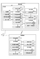
- FIG. 23 is a block diagram showing a configuration of an imaging system according to a modification of the second embodiment of the present invention.
- FIG. 24 is a block diagram showing a configuration of an imaging system according to Embodiment 3 of the present invention.
- FIG. 25 is a flowchart showing the operation of the imaging device shown in FIG.
- FIG. 26 is a flow chart showing the operation of the communication device shown in FIG.
- FIG. 1 is a block diagram showing a configuration of an imaging system 1 according to Embodiment 1 of the present invention.
- the imaging system 1 includes an imaging device 2 (FIG. 1) and a communication device 3 (FIG. 1) which are respectively operated by different users and connectable to transmit and receive information by wireless communication.
- the imaging system 1 is not limited to wireless communication, and may have a configuration in which the imaging device 2 and the communication device 3 are connected so as to mutually transmit and receive information by wired communication.
- the user of the communication device 3 performs an operation related to an operation instruction (advice) to the user of the imaging device 2 with respect to the communication device 3, whereby the imaging device 2 at a location away from the communication device 3
- an operation instruction (advice)
- the imaging device 2 at a location away from the communication device 3
- FIG. 2 is a perspective view of the state in which the first display unit 291 of the imaging device 2 is positioned at the reference position, as viewed from the side facing the user of the imaging device 2.
- FIG. 3 is a perspective view of a state in which the first display unit 291 of the imaging device 2 is positioned at the self-shooting position, as viewed from the subject side of the imaging device 2. 2 and 3, the width direction of the imaging device 2 is taken as an X axis, the height direction of the imaging device 2 as a Y axis, and the light axis L direction of the imaging device 2 as a Z axis.
- the imaging device 2 is a device for imaging an object, and is configured as an electronic device such as a digital camera, a digital video camera, a mobile phone having a photographing function, a tablet type portable device, an endoscope, or a microscope.
- the main part of the present invention will be mainly described as the configuration of the imaging device 2.
- the imaging device 2 includes a main body 2A and a display mechanism 2B, as shown in FIGS. 1 to 3.
- the main body unit 2A includes an imaging unit 20, a position acquisition unit 21, a first orientation acquisition unit 22, a first input unit 23, a first communication unit 24, and a first memory unit 25. And a first recording unit 26, a rotation determination unit 27, and a first control unit 28.
- the imaging unit 20 captures an image of a subject under control of the first control unit 28 and generates image data.
- the imaging unit 20 includes an optical system for forming an image of an object, an imaging element such as a CCD (Charge Coupled Device) for receiving an object image formed by the optical system and converting it into an electrical signal, and an electrical signal from the imaging element It is configured using a signal processing unit or the like that generates digital image data by performing signal processing (such as A / D conversion) on (analog signal). Then, the image data generated by the imaging unit 20 is sequentially stored in the first memory unit 25 under the control of the first control unit 28, and the user of the imaging device 2 inputs the image data to the first input unit 23. It is recorded in the first recording unit 26 according to the photographing operation.
- an imaging element such as a CCD (Charge Coupled Device) for receiving an object image formed by the optical system and converting it into an electrical signal, and an electrical signal from the imaging element It is configured using a signal processing unit or the like that generates digital image data by performing signal processing (such as A / D conversion) on (analog signal). Then, the image data
- the position acquisition unit 21 receives orbit information of satellites transmitted from a plurality of GPS satellites constituting a GPS (Global Positioning System), which is measurement means for measuring the position of an object on the ground, and receives the received orbit information. Based on the position information of the imaging device 2 (information about longitude and latitude) is acquired. Then, the position acquisition unit 21 outputs the position information of the imaging device 2 to the first control unit 28.
- GPS Global Positioning System
- the first azimuth acquisition unit 22 sets the direction in which the optical axis L faces the viewing area as the reference azimuth.
- the orientation of the imaging device 2 at the time of acquisition is acquired as first orientation information.
- the first direction acquisition unit 22 outputs the first direction information of the imaging device 2 to the first control unit 28.
- the first direction acquisition unit 22 is configured using a magnetic direction sensor or the like, detects components in the vertical direction and horizontal direction of the geomagnetism, and a reference direction based on the north and the optical axis L of the imaging device 2
- the first azimuth information of the imaging device 2 is acquired by detecting the angle formed by the angle as the azimuth angle.
- the first input unit 23 is configured using a button, a switch, or the like that receives a user operation (see FIGS. 2 and 3), and outputs an instruction signal according to the user operation to the first control unit 28.
- the first communication unit 24 performs wireless communication of various data including live view image data and signals necessary for communication with the communication device 3 according to a predetermined protocol under the control of the first control unit 28.
- the first memory unit 25 stores image data generated by the imaging unit 20, operation instruction information received from the communication device 3 via the first communication unit 24, and the like.
- the first recording unit 26 includes a first program recording unit 261 and an image data recording unit 262.
- the first program recording unit 261 records various programs (including an imaging program) executed by the first control unit 28 and various data used during the execution of the programs.
- the image data recording unit 262 records the image data generated by the imaging unit 20 under the control of the first control unit 28.
- the rotation determination unit 27 determines the rotation state of the display mechanism 2B, and outputs the determination result to the first control unit 28. Specifically, the rotation determination unit 27 determines whether or not the first display unit 291 is located at the self-shooting position (FIG. 3), and outputs the determination result to the first control unit 28.
- the first control unit 28 is configured using a CPU (Central Processing Unit) or the like, and transfers instructions or data corresponding to each unit constituting the imaging device 2 according to an instruction signal from the first input unit 23 or the like. And control the operation of the imaging device 2 in an integrated manner.
- the first control unit 28 includes a first communication control unit 281, a first display control unit 282, a pseudo image generation unit 283, an imaging control unit 284, and a position determination unit 285.
- the first communication control unit 281 controls the operation of the first communication unit 24 and performs wireless communication with the communication device 3. Specifically, the first communication control unit 281 sequentially transmits the live view image data sequentially generated by the imaging unit 20 and sequentially stored in the first memory unit 25 via the first communication unit 24.
- the first communication control unit 281 responds to an operation (hereinafter, referred to as an advice request operation) for receiving an advice of a shooting spot to the first input unit 23 by the user of the imaging device 2, that is, the first input.
- an advice request operation for receiving an advice of a shooting spot to the first input unit 23 by the user of the imaging device 2, that is, the first input.
- the position information and the first azimuth information acquired by the position acquisition unit 21 and the first azimuth acquisition unit 22 are transmitted to the communication device 3 through the first communication unit 24 based on the instruction signal from the unit 23 .
- the first communication control unit 281 receives the operation instruction information from the communication device 3 via the first communication unit 24.
- the first display control unit 282 controls the operation of the first display unit 291 configuring the display mechanism 2B, and causes the first display unit 291 to display an image. Specifically, the first display control unit 282 reads the live view image data stored in the first memory unit 25 and displays a live view image corresponding to the live view image data on the first display unit 291 (live view Display). Further, the first display control unit 282 causes the first display unit 291 to display a superimposed image obtained by superimposing the pseudo image generated by the pseudo image generation unit 283 on the live view image. Further, the first display control unit 282 reads the image data recorded in the image data recording unit 262, and causes the first display unit 291 to display an image corresponding to the image data.
- the first display control unit 282 displays the first display control unit 282 on the main body unit 2A.
- the target image is inverted and displayed on the first display unit 291 (mirror inverted display).
- the first display control unit 282 may cause the first display unit 291 to display the image to be displayed after reversing the image to be displayed with respect to the main body unit 2A.
- the first display control unit 282 may cause the first display unit 291 to display the image as the display target as it is without inverting the image to be displayed.
- the pseudo image generation unit 283 receives the operation instruction information via the first communication unit 24, a pseudo image that simulates the operation of the user of the imaging device 2 according to the operation instruction based on the operation instruction information Generate
- the operation instruction information is imaging instruction information regarding an imaging instruction (advising an imaging spot) for instructing imaging at a specific place. Then, based on the position information and the first direction information acquired by the position acquisition unit 21 and the first direction acquisition unit 22 at the time of receiving the image acquisition instruction information, the pseudo image generation unit 283 determines A pseudo image (hereinafter, referred to as a first pseudo image) for guiding the user of the imaging device 2 to the imaging spot based on the imaging instruction information is generated.
- a pseudo image hereinafter, referred to as a first pseudo image
- the imaging control unit 284 causes the imaging unit 20 to capture a subject according to a shooting operation by the user of the imaging device 2 to the first input unit 23, and image data generated by the imaging unit 20 by the imaging is image data The image is recorded in the recording unit 262.
- the position determination unit 285 sets a shooting spot based on the shooting instruction information based on the shooting instruction information stored in the first memory unit 25 and the position information acquired by the position acquisition unit 21 (see FIG. It is determined whether it is located within a predetermined distance from the target position).
- the display mechanism 2B is provided rotatably with respect to the main body 2A, as shown in FIG. 2 or 3, and is a reference position (FIG. 2) on the user side (rear side) of the imaging device 2 or the subject side. It is positioned at the (front side) self-shooting position (FIG. 3). As shown in FIGS. 1 to 3, the display mechanism 2B includes a first display portion 291, a movable portion 292 (FIGS. 2 and 3), and a rotation support portion 293 (FIGS. 2 and 3).
- the first display unit 291 is configured using a display panel made of liquid crystal, organic EL (Electro Luminescence) or the like, and displays a live view image or a first superimposed image under the control of the first display control unit 282. In addition, the first display unit 291 appropriately displays operation information of the imaging device 2 and information related to imaging.
- the first display portion 291 is attached to the movable portion 292, and the movable portion 292 is attached to the main body portion 2A rotatably around one end of the main body portion 2A via a rotation support portion 293 such as a hinge.
- the movable portion 292 has the main portion 2A such that the first display portion 291 is positioned at the reference position (FIG. 2) or the self-shooting position (FIG. 3) with the axis R of the rotation support portion 293 as the center Is rotatably attached to the
- the communication device 3 is a device that performs wireless communication with the imaging device 2 and is configured as, for example, a digital camera, a digital video camera, a mobile phone or a tablet-type portable device, a personal computer, or the like.
- the main part of the present invention will be mainly described as the configuration of the communication device 3.
- the communication device 3 includes a second display unit 31, a second input unit 32, a second communication unit 33, a second memory unit 34, a second recording unit 35, and a second recording unit 35. And a control unit 36.
- the second display unit 31 is configured using a display panel made of liquid crystal, organic EL, or the like, and displays various images under the control of the second control unit 36.
- the second input unit 32 is configured using a button, a switch, a touch panel, a microphone, and the like. That is, the second input unit (button, switch) 32 receives a user operation by the user of the communication device 3, and outputs an instruction signal corresponding to the user operation to the second control unit 36.
- the second input unit (touch panel) 32 detects a touch of an object from the outside, and outputs a position signal corresponding to the detected touch position to the second control unit 36.
- the second input unit (microphone or the like) 32 inputs words (speech) uttered by the user of the communication device 3 and converts them into electric signals, performs sampling and quantization on the converted electric signals, Audio data is generated by performing D conversion, and the audio data is output to the second control unit 36.
- the second input unit 32 has a function as a second operation receiving unit according to the present invention.
- the second communication unit 33 performs wireless communication of various data including live view image data and signals necessary for communication with the imaging device 2 according to a predetermined protocol under the control of the second control unit 36.
- the second memory unit 34 stores live view image data transmitted from the imaging device 2 and received via the second communication unit 33, position information, first direction information, and the like.
- the second recording unit 35 includes a second program recording unit 351 and a map information recording unit 352.
- the second program recording unit 351 records various programs executed by the second control unit 36 and various data used during execution of the programs.
- the map information recording unit 352 records map information including the longitude and the latitude of each point.
- the second control unit 36 is configured using a CPU or the like, and transfers instructions or data corresponding to each unit that configures the communication device 3 according to an instruction signal from the second input unit 32, a position signal, voice data, etc. Etc. to comprehensively control the operation of the communication device 3.
- the second control unit 36 includes a second communication control unit 361, a second display control unit 362, and an operation instruction information generation unit 363.
- the second communication control unit 361 controls the operation of the second communication unit 33 and performs wireless communication with the imaging device 2. Specifically, the second communication control unit 361 sequentially receives live view image data from the imaging device 2 via the second communication unit 33, and the operation instruction information generated by the operation instruction information generation unit 363. Is sent to the imaging device 2.
- the second display control unit 362 causes the second display unit 31 to display various images (for example, live view images corresponding to live view image data received via the second communication unit 33).
- the operation instruction information generation unit 363 responds to an operation related to an operation instruction to the second input unit 32 by the user of the communication device 3, that is, based on an instruction signal from the second input unit 32, a position signal, or voice data. , Generating operation instruction information related to an operation instruction for the user of the imaging device 2
- operation instruction information generation unit 363 responds to an operation (hereinafter referred to as a first advice operation) relating to an instruction (photographing spot advice) to the second input unit 32 by the user of communication device 3.
- imaging instruction information information on the longitude and latitude of the imaging spot (target position) related to the imaging instruction is generated.
- the first advice operation described above corresponds to a second operation according to the present invention.
- FIG. 4 is a flowchart showing the operation of the imaging device 2.
- the first control unit 28 causes the imaging unit 20 to start imaging (step S102). : Imaging step).
- the image data generated by the imaging unit 20 is sequentially stored in the first memory unit 25.
- the first communication control unit 281 sequentially transmits the latest live view image data stored in the first memory unit 25 to the communication device 3 via the first communication unit 24 (step S103: communication step) ).
- the first control unit 28 starts display of the first superimposed image in step S110 described later, and determines whether or not the first superimposed image is being displayed (step S104).
- the imaging device 2 proceeds to step S109.
- the first display control unit 282 reads the latest live view image data stored in the first memory unit 25. , And causes the first display unit 291 to start live view display (step S105).
- the first communication control unit 281 determines whether the user of the imaging device 2 has made an advice request operation to the first input unit 23 (step S106). If the first communication control unit 281 determines that an advice request operation has been performed (step S106: Yes), the position acquisition unit 21 and the first direction acquisition unit 22 acquire each when the operation is performed. The position information and the first azimuth information are transmitted to the communication device 3 via the first communication unit 24 (step S107). On the other hand, when it is determined that the advice request operation has not been made (step S106: No), the imaging device 2 proceeds to step S108.
- the first communication control unit 281 receives the imaging instruction information (the imaging spot from the communication device 3 via the first communication unit 24). It is judged whether (information about the longitude and latitude of (target position)) is received (step S108: communication step). When it is determined that the imaging instruction information has not been received (step S108: No), the imaging device 2 proceeds to step S113. On the other hand, when it is determined that the imaging instruction information has been received (step S108: Yes), the first control unit 28 stores the imaging instruction information in the first memory unit 25. Then, the pseudo image generation unit 283 generates a first pseudo image (step S109: pseudo image generation step). Even when it is determined that the first superimposed image is being displayed (step S104: Yes), the pseudo image generation unit 283 generates a first pseudo image in step S109.
- the first display control unit 282 applies the first pseudo image generated in step S109 to the live view image corresponding to the latest live view image data stored in the first memory unit 25.
- the superimposed first superimposed image is displayed on the first display unit 291 (step S110: display step).
- the position determination unit 285 determines that the current position of the imaging device 2 is based on the imaging instruction information. It is determined whether the target position (the position of the imaging spot) is within a predetermined distance range (step S111).
- Step S111: No When it is determined that the current position of the imaging device 2 is not located within the range of the predetermined distance from the target position (Step S111: No), the imaging device 2 proceeds to Step S113. On the other hand, when it is determined that the current position of the imaging device 2 is located within the range of the predetermined distance from the target position (step S111: Yes), the first display control unit 282 selects the first display unit 291. The display state is switched from the display of the first superimposed image to the live view display (step S112).
- step S112 if it is determined that the photographing instruction information is not received in step S108 (step S108: No), or the current position of the imaging device 2 is positioned within a predetermined distance from the target position in step S111. If it is determined not (step S111: No), the imaging control unit 284 determines whether the user of the imaging device 2 has performed an imaging operation on the first input unit 23 (step S113). If it is determined that there is no shooting operation (step S113: No), the imaging device 2 returns to step S101.
- step S113 when it is determined that a shooting operation has been performed (step S113: Yes), the imaging control unit 284 causes the imaging unit 20 to capture a subject, and the image data generated by the imaging unit 20 by the imaging is image data The image is recorded in the recording unit 262 (step S114). Thereafter, the imaging device 2 returns to step S101.
- FIG. 5 is a flowchart showing the operation of the communication device 3.
- the second communication control unit 361 starts the second communication unit 33 from the imaging device 2. It is determined whether live view image data has been received via the interface (step S202). If it is determined that the live view image data has not been received (step S202: No), the communication device 3 returns to step S201. On the other hand, when it is determined that the live view image data has been received (step S202: Yes), the second control unit 36 sequentially stores the received live view image data in the second memory unit 34. Further, the second control unit 36 starts display of the designation screen in step S206 described later, and determines whether or not the designation screen is being displayed (step S203).
- step S203: Yes If it is determined that the designation screen is being displayed (step S203: Yes), the communication device 3 proceeds to step S206.
- step S203: No the second display control unit 362 sequentially reads the live view image data stored in the second memory unit 34, 2. Display (live view display) a live view image corresponding to the live view image data on the display unit 31 (step S204).
- the second communication control unit 361 determines whether the position information and the first orientation information of the imaging device 2 have been received from the imaging device 2 via the second communication unit 33 (step S205). If it is determined that the position information of the imaging device 2 and the first direction information have not been received (step S205: No), the communication device 3 returns to step S201. On the other hand, when it is determined that the position information of the imaging device 2 and the first orientation information have been received (step S205: Yes), the second display control unit 362 advises the user of the imaging device 2 of the imaging spot.
- the second display unit 31 displays a designation screen for setting (step S206).
- the second display control unit 362 causes the second display unit 31 to display the designation screen also when it is determined that the designation screen is being displayed (step S203: Yes).
- the operation instruction information generation unit 363 determines whether or not the user of the communication device 3 has performed the first advice operation on the second input unit 32 (step S207). If it is determined that there is no first advice operation (step S207: No), the communication device 3 returns to step S201. On the other hand, when it is determined that the first advice operation has been made (step S207: Yes), the operation instruction information generation unit 363 generates imaging instruction information related to the imaging instruction (step S208). Subsequently, the second communication control unit 361 transmits the imaging instruction information generated in step S208 to the imaging device 2 via the second communication unit 33 (step S209). After this, the communication device 3 returns to step S201.
- FIG. 6 is a view schematically showing the posture of the user of the imaging device 2 at the time of operation of the imaging system 1.
- FIG. 7 is a view showing an example of an image displayed on the imaging device 2 and the communication device 3 when the user of the imaging device 2 performs an advice request operation at the time of operation of the imaging system 1.
- the user CU of the imaging device 2 takes a self-portrait shooting in which the user CU is photographed as a subject while holding the imaging device 2 positioned with the first display portion 291 at the self-shooting position with the left hand. The case where it carries out is demonstrated to an example.
- a live view image currently displayed is set as a live view image W100 shown in FIG. 7A.
- an advice request operation for example, the first input unit 23 is configured to the first input unit 23
- An operation of pressing any button among the buttons is performed.
- the imaging device 2 determines that an advice request operation has been made (step S106: Yes), and the position information of the imaging device 2 at the time of the operation
- the first direction information is transmitted to the communication device 3 (step S107).
- step S206 the second display control unit 362 reads map information of a predetermined scale including longitude and latitude based on the position information of the imaging device 2 from the map information recording unit 352. Further, the second display control unit 362 reads the latest live view image stored in the second memory unit 34. Then, as shown in FIG. 7B, the second display control unit 362 superimposes the live view image W200 corresponding to the latest live view image data on the map image M corresponding to the map information. .
- the second display control unit 362 is a position image that indicates the position and orientation of the imaging device 2 in the map image M, based on the position information of the imaging device 2 and the first orientation information for the map image M. (Black circle) P and the first orientation image (arrow) O are superimposed. Then, the second display control unit 362 causes the second display unit 31 to display a designation screen Sp in which the live view image W200, the position image P, and the first azimuth image O are superimposed on the map image M.
- the imaging device 2 has a posture in which the imaging device 2 faces the direction (left direction) of the arrow of the first orientation image O at the position of the position image P in the map image M. It is held by the user CU.
- the user CU of the imaging device 2 stands at a position on the tip end side of the arrow of the first orientation image O in a posture facing the base end side (right direction) of the arrow.
- the imaging device 2 sequentially displays the live view image W100 corresponding to the latest live view image data while sequentially transmitting the latest live view image data (step S103) (step S105). Then, in step S204 or step S206, the communication device 3 sequentially displays the live view image W200 corresponding to the latest live view image data. Therefore, as shown in FIG. 7B, the live view image W200 displayed by the communication device 3 is substantially the same as the live view image W100 displayed by the imaging device 2 (FIG. 7A). It becomes.
- the user of the communication device 3 confirms the designation screen Sp displayed on the communication device 3. Then, when the user of the communication device 3 wants to advise the user CU of the imaging device 2 of the imaging spot (for example, he wants to advise the imaging spot near the position of the user CU of the imaging device 2 in the map image M In the case, etc.), the designated shooting spots S1 to S6 (see FIGS. 8 to 13) on the display screen (second input unit (touch panel) 32) in the communication device 3 are touched with a finger.
- the designated imaging spots S1 to S6 will be described in order.
- FIG. 8 is a view showing an example of a first advice operation (instruction of designated shooting spot S1) performed by the user of the communication device 3 at the time of operation of the imaging system 1, and a first superimposed image displayed on the imaging device 2.
- the designation screen Sp shown in FIG. 8 (b) is the same designation screen as the designation screen Sp shown in FIG. 7 (b). The same applies to the designation screen Sp shown in FIGS. 9 (b), 10 (b), 11 (b), 12 (b), and 13 (b).
- the communication device 3 performs the first advice operation based on the position signal from the second input unit (touch panel) 32.
- step S207 Yes. Then, the communication device 3 generates imaging instruction information (information on the longitude and the latitude of the designated imaging spot S1 corresponding to the touch position in the map image M) (step S208), and transmits the imaging instruction information to the imaging device 2 (Step S209).
- imaging instruction information information on the longitude and the latitude of the designated imaging spot S1 corresponding to the touch position in the map image M
- the imaging device 2 acquires the imaging instruction information at the time when the imaging instruction information is received in step S109.
- the positional relationship between the current position and orientation in the imaging device 2 and the position (target position) of the designated imaging spot S1 is recognized on the basis of the positional information, the first azimuth information, and the imaging instruction information.
- the imaging device 2 recognizes that the target position is the right side (left side of the imaging device 2) of the user CU of the imaging device 2.
- the imaging device 2 is a first pseudo image Q1A in which a motion of a person walking on the right side (right side of the user CU of the imaging device 2) is simulated. (FIG. 8A) is generated. Moreover, the imaging device 2 generates distance information (distance image D (FIG. 8A)) regarding the distance from the current position of the imaging device 2 to the target position based on the current position of the imaging device 2 and the target position. Do. Then, the imaging device 2 superimposes the first pseudo image Q1A, the distance image D, and the arrow image A1A in the right direction (FIG. 8A) on the live view image W100 corresponding to the latest live view image data. The first superimposed image Su1A (FIG. 8A) is displayed (step S110).
- FIG. 9 is a view showing an example of a first advice operation (instruction of designated shooting spot S2) performed by the user of the communication device 3 at the time of operation of the imaging system 1, and a first superimposed image displayed on the imaging device 2.
- the communication device 3 is information on the longitude and latitude of the designated imaging spot S2 corresponding to the touch position in the map image M
- the imaging instruction information including the information is generated (step S208), and the imaging instruction information is transmitted to the imaging device 2 (step S209).
- the imaging device 2 receives the imaging instruction information (step S108: Yes)
- the position (target position) of the designated imaging spot S2 is processed in the same process as when the designated imaging spot S1 is instructed in step S109. Recognizes that the user CU of the imaging device 2 is on the left side. Then, the imaging device 2 generates a first pseudo image Q1B (FIG. 9A) in which the motion of a person walking to the left is artificially expressed. Further, the imaging device 2 performs distance information related to the distance from the current position of the imaging device 2 to the target position by the same processing as when the designated imaging spot S1 is instructed (distance image D (FIG. 9A)).
- the imaging device 2 is a first superimposed image Su1B (FIG. 9) in which the first pseudo image Q1B, the distance image D, and the left arrow image A1B (FIG. 9A) are superimposed on the live view image W100.
- (A) is displayed (step S110).
- FIG. 10 is a diagram showing an example of a first advice operation (instruction of designated shooting spot S3) performed by the user of the communication device 3 at the time of operation of the imaging system 1 and an example of a first superimposed image displayed on the imaging device 2.
- the communication device 3 relates to the longitude and latitude of the designated shooting spot S3 corresponding to the touch position in the map image M.
- Imaging instruction information including information is generated (step S208), and the imaging instruction information is transmitted to the imaging device 2 (step S209).
- the imaging device 2 receives the imaging instruction information (step S108: Yes)
- the position (target position) of the designated imaging spot S3 is processed in the same process as when the designated imaging spot S1 is instructed in step S109. Recognizes that the user CU of the imaging device 2 is on the rear side. Then, the imaging device 2 generates a first pseudo image Q1C (FIG. 10A) in which the motion of a person walking backward is represented in a pseudo manner (the walking person gradually decreases). .
- the imaging device 2 performs distance information related to the distance from the current position of the imaging device 2 to the target position by the same processing as when the designated imaging spot S1 is instructed (distance image D (FIG. 10A)). Generate Then, the imaging device 2 displays a first superimposed image Su1C (FIG. 10A) in which the first pseudo image Q1C and the distance image D are superimposed on the live view image W100 (step S110).
- FIG. 11 is a view showing an example of a first advice operation (instruction of designated imaging spot S4) performed by the user of the communication device 3 at the time of operation of the imaging system 1 and an example of a first superimposed image displayed on the imaging device 2.
- communication device 3 relates to the longitude and latitude of designated shooting spot S4 corresponding to the touch position in map image M.
- Imaging instruction information including information is generated (step S208), and the imaging instruction information is transmitted to the imaging device 2 (step S209).
- the imaging device 2 receives the imaging instruction information (step S108: Yes)
- the position (target position) of the designated imaging spot S4 is processed in the same process as when the designated imaging spot S1 is instructed in step S109. Recognizes that the user CU of the imaging device 2 is in front of the user CU. Then, the imaging device 2 generates a first pseudo image Q1D (FIG. 11A) in which the motion of a person walking forward is expressed in a pseudo manner (the walking person gradually increases). . Further, the imaging device 2 performs distance information related to the distance from the current position of the imaging device 2 to the target position by the same processing as when the designated imaging spot S1 is instructed (distance image D (FIG. 11 (a))). Generate Then, the imaging device 2 displays a first superimposed image Su1D (FIG. 11A) in which the first pseudo image Q1D and the distance image D are superimposed on the live view image W100 (step S110).
- FIG. 12 is a view showing an example of a first advice operation (instruction of designated shooting spot S5) performed by the user of the communication device 3 at the time of operation of the imaging system 1 and an example of a first superimposed image displayed on the imaging device 2.
- the communication device 3 determines the longitude of the designated imaging spot S5 corresponding to the touch position in the map image M and The photographing instruction information including the information on the latitude is generated (step S208), and the photographing instruction information is transmitted to the imaging device 2 (step S209).
- the imaging device 2 receives the imaging instruction information (step S108: Yes)
- the position (target position) of the designated imaging spot S5 is processed in the same process as when the designated imaging spot S1 is instructed in step S109. Recognizes that the user CU of the imaging device 2 is on the right rear side.
- the imaging device 2 is a first pseudo image Q1E (Fig. 12) in which the motion of a person walking in the diagonally backward right direction is expressed in a pseudo manner (the walking person gradually decreases while moving to the right). Generate (a).
- the imaging device 2 performs distance information related to the distance from the current position of the imaging device 2 to the target position by the same processing as when the designated imaging spot S1 is instructed (distance image D (FIG.
- the imaging device 2 is directed to the first pseudo image Q1E, the distance image D, and an arrow image A1E (FIG. 12A) which is turned toward the right and toward the right.
- the superimposed first superimposed image Su1E (FIG. 12A) is displayed (step S110).
- FIG. 13 is a view showing an example of a first advice operation (instruction of designated shooting spot S6) performed by the user of the communication device 3 at the time of operation of the imaging system 1, and a first superimposed image displayed on the imaging device 2.
- the communication device 3 determines the longitude of the designated shooting spot S6 corresponding to the touch position in the map image M and The photographing instruction information including the information on the latitude is generated (step S208), and the photographing instruction information is transmitted to the imaging device 2 (step S209).
- the imaging device 2 receives the imaging instruction information (step S108: Yes)
- the position (target position) of the designated imaging spot S6 is processed in the same process as in the case where the designated imaging spot S1 is instructed in step S109. Recognizes that the user CU of the imaging device 2 is on the left front side. Then, the imaging device 2 is a first pseudo image Q1F (Fig. 13) in which a motion of a person walking diagonally forward to the left is expressed in a pseudo manner (the walking person gradually increases while moving to the left). Generate (a).
- the imaging device 2 performs distance information related to the distance from the current position of the imaging device 2 to the target position by the same processing as when the designated imaging spot S1 is instructed (distance image D (FIG. 13 (a))). Generate Then, with respect to the live view image W100, the imaging device 2 is directed to the first pseudo image Q1F, the distance image D, and an arrow image A1F (FIG. 13A) that is thicker toward the left and toward the left. The superimposed first superimposed image Su1F (FIG. 13A) is displayed (step S110).
- the imaging device 2 When the imaging device 2 according to the first embodiment described above receives the operation instruction information from the external communication device 3, the imaging device 2 operates the user of the imaging device 2 according to the operation instruction based on the operation instruction information. Generate a pseudo image represented pseudo. Then, the imaging device 2 displays the pseudo image. Therefore, the user of the imaging device 2 can recognize the operation instruction instructed by the user of the communication device 3 from the pseudo image displayed on the imaging device 2 and perform the operation according to the operation instruction. That is, the user of the communication device 3 can give various advices to the user of the imaging device 2 without using other communication means such as a mobile phone. In particular, the imaging device 2 generates and displays the above-described pseudo image, not a figure such as a character or an arrow, according to the operation instruction (advice).
- the convenience can be improved.
- the imaging device 2 includes the position acquisition unit 21 and the first orientation acquisition unit 22 that acquire the position information and the first orientation information of the imaging device 2. Therefore, when the operation instruction information is imaging instruction information (including information regarding the longitude and latitude of the imaging spot) regarding the advice of the imaging spot, the imaging device 2 communicates the user of the imaging device 2 from the current position to the communication device. It is possible to generate and display a first pseudo image for guiding to the imaging spot instructed by the user 3. In addition, the imaging device 2 can generate and display a distance image regarding the distance from the current position of the imaging device to the imaging spot instructed by the user of the communication device 3.
- the operation instruction information is imaging instruction information (including information regarding the longitude and latitude of the imaging spot) regarding the advice of the imaging spot
- the imaging device 2 communicates the user of the imaging device 2 from the current position to the communication device. It is possible to generate and display a first pseudo image for guiding to the imaging spot instructed by the user 3.
- the imaging device 2 can generate and display a distance image regarding the distance from the current position of the
- the user of the imaging device 2 grasps the first pseudo image and the distance image, it immediately determines whether or not the instruction from the communication device 3 is followed (for example, when it is determined that the distance to the imaging spot is long) If you do not follow the instructions and if you do not follow the instructions, you can perform another advice request operation to receive another shooting spot advice.
- the imaging device 2 is acquired by the position acquisition unit 21 when the user performs the advice request operation to the first input unit 23 by the user of the imaging device 2.
- the position information is transmitted to the communication device 3. Therefore, the communication device 3 may display a map of a predetermined scale including longitude and latitude based on the position information of the imaging device 2 as a designation screen for advising the user of the imaging device 2 of a shooting spot it can. Therefore, the user of the communication device 3 can advise the photographing spot relatively close to the current position of the imaging device 2 from the designated screen.
- the subject is a user of the imaging device 2. Then, when the first display unit 291 is positioned at the self shooting position, the imaging device 2 reverses the image to be displayed on the main body unit 2A and displays the image on the first display unit 291. For this reason, the user of the imaging device can clearly recognize the direction of the imaging spot based on the first pseudo image, even when performing self-shooting.
- the imaging device 2 transmits live view image data to the communication device 3. Then, the communication device 3 displays a live view image corresponding to the received live view image data. For this reason, the user of the communication device 3 can grasp the clothes and the like of the subject, and can advise the shooting spot according to the subject.
- the imaging device 2 generates a pseudo image (first pseudo image) only when it receives advice of a shooting spot from the user of the communication device 3 (when shooting instruction information is received).
- the first superimposed image in which the first pseudo image is superimposed on the live view image is displayed.
- the imaging device generates the first pseudo image and displays the first superimposed image in the above case, and receives an advice of the camera angle of the imaging device with respect to the subject ( When angle change instruction information is received, a pseudo image (second pseudo image) is generated, and a second superimposed image in which the second pseudo image is superimposed on the live view image is displayed.
- the imaging system according to the second embodiment has the same configuration as the imaging system 1 described in the first embodiment described above.
- an operation of the imaging system 1 according to the second embodiment an operation of the imaging device 2 (an imaging method according to the present invention) and an operation of the communication device 3 will be described.
- FIG. 14 is a flowchart showing an operation of the imaging device 2 according to Embodiment 2 of the present invention.
- steps S115 to S120 are added to the operation (FIG. 4) of the imaging device 2 described in the first embodiment described above. Only the points are different. Therefore, hereinafter, only steps S115 to S120 will be described.
- Step S115 is performed after step S103. Specifically, the first control unit 28 starts display of the second superimposed image in step S120 described later, and determines whether or not the second superimposed image is being displayed (step S115). When it is determined that the second superimposed image is being displayed (step S115: Yes), the imaging device 2 proceeds to step S119. On the other hand, when it is determined that the first superimposed image is not being displayed (step S115: No), the imaging device 2 proceeds to step S104.
- Step S116 is performed after step S112. Specifically, the first communication control unit 281 determines whether or not the user of the imaging device 2 has performed an operation of setting the imaging conditions to the first input unit 23 (step S116).
- the shooting condition setting operation is an operation for receiving advice on the camera angle of the imaging device 2 with respect to the subject, and for example, when shooting in a model-like manner, inputting the shooting condition (model wind etc.) Can be illustrated.
- the imaging condition setting operation described above corresponds to a first operation according to the present invention.
- the first input unit 23 has a function as a first operation receiving unit according to the present invention.
- step S116: No When it is determined that the photographing condition setting operation has not been made (step S116: No), the imaging device 2 proceeds to step S113. On the other hand, when it is determined that the imaging condition setting operation has been performed (step S116: Yes), the first communication control unit 281 transmits the imaging condition input or the like by the imaging condition setting operation via the first communication unit Shooting condition information on the communication device 3 is transmitted to the communication device 3 (step S117).
- step S117 or when it is determined that the photographing instruction information has not been received (step S108: No), the first communication control unit 281 makes an angle from the communication device 3 via the first communication unit 24. It is determined whether or not change instruction information has been received (step S118). When it is determined that the angle change instruction information has not been received (step S118: No), the imaging device 2 proceeds to step S113. On the other hand, when it is determined that the angle change instruction information has been received (step S118: Yes), the first control unit 28 stores the angle change instruction information in the first memory unit 25.
- the pseudo image generation unit 283 generates a second pseudo image for causing the user of the imaging device 2 to change the camera angle of the imaging device 2 based on the angle change instruction information stored in the first memory unit 25. (Step S119: pseudo image generation step). Even when it is determined that the second superimposed image is being displayed (step S115: Yes), the pseudo image generation unit 283 generates a second pseudo image in step S119.
- step S119 the first display control unit 282 generates the second pseudo image generated in step S119 for the live view image corresponding to the latest live view image data stored in the first memory unit 25.
- the superimposed second superimposed image is displayed on the first display unit 291 (step S120: display step). Thereafter, the imaging device 2 proceeds to step S113.
- FIG. 15 is a flowchart showing an operation of the imaging device 2 according to Embodiment 2 of the present invention.
- steps S210 to S215 are added to the operation (FIG. 5) of the imaging device 2 described in the first embodiment described above. Only the points are different. Therefore, hereinafter, only steps S210 to S215 will be described.
- Step S210 is executed after it is determined that the designation screen is not being displayed (step S203: No). Specifically, the first control unit 28 starts display of the condition superimposed image in step S212 described later, and determines whether or not the condition superimposed image is being displayed (step S210). When it is determined that the condition-superimposed image is being displayed (step S210: Yes), the imaging device 2 proceeds to step S212. On the other hand, when it is determined that the condition-superimposed image is not being displayed (step S210: No), the imaging device 2 proceeds to step S204.
- Step S211 is executed after it is determined that the position information of the imaging device 2 and the first direction information are not received (step S205: No). Specifically, the second communication control unit 361 determines whether the imaging condition information has been received from the imaging device 2 via the second communication unit 33 (step S211). If it is determined that the imaging condition information has not been received (step S211: No), the communication device 3 returns to step S201. On the other hand, when it is determined that the shooting condition information has been received (step S211: Yes), the second display control unit 362 performs live view corresponding to the latest live view image data stored in the second memory unit 34. The second display unit 31 displays a condition superimposed image in which a photographing condition based on the photographing condition information is superimposed on the image (step S212).
- the operation instruction information generation unit 363 describes an operation (hereinafter referred to as a second advice operation) related to an angle change instruction (advection of the camera angle of the imaging device 2 with respect to a subject) by the user of the communication device 3 to the second input unit 32. ) Is judged (step S213).
- the second advice operation described above corresponds to the second operation according to the present invention. If it is determined that there is no second advice operation (step S213: No), the communication device 3 returns to step S201. On the other hand, when it is determined that the second advice operation has been made (step S213: Yes), the operation instruction information generation unit 363 generates angle change instruction information related to the angle change instruction (step S214). Subsequently, the second communication control unit 361 transmits the angle change instruction information generated in step S214 to the imaging device 2 via the second communication unit 33 (step S215). After this, the communication device 3 returns to step S201.
- step S212 the communication device 3 superimposes a condition in which the photographing condition C such as model wind is superimposed on the live view image W201 corresponding to the latest live view image data based on the photographing condition information received from the imaging device 2
- the image Sc is displayed (see FIGS. 16 to 22).
- the user of the communication device 3 grasps the imaging condition C requested by the user CU of the imaging device 2 by confirming the condition superimposed image Sc displayed on the communication device 3.
- the user of the communication device 3 wants to give the user CU of the imaging device 2 advice (advice on the positional relationship between the imaging device 2 and the user CU of the imaging device 2) according to the imaging condition C.
- the user of the communication device 3 issues words W1 to W7 (see FIGS. 16B to 22B) as the second advice operation will be described in order.
- FIG. 16 is a view showing an example of a second advice operation (word W1) performed by the user of the communication device 3 at the time of operation of the imaging system 1 and a second superimposed image displayed on the imaging device 2.
- word W1 such as “low”
- the communication device 3 is based on voice data (voice data corresponding to the word W1) from the second input unit (microphone or the like) 32. It is determined that the second advice operation has been made (step S213: Yes). Further, the communication device 3 analyzes the voice data, generates angle change instruction information on low angle shooting advice (angle change instruction) (step S214), and transmits it to the imaging device 2 (step S215).
- step S118 when the imaging device 2 receives angle change instruction information (step S118: Yes), a person makes the user CU of the imaging device 2 shoot at a low angle based on the angle change instruction information.
- Pseudo-represents an operation of lowering the gripped camera (pseudo-represents a state in which the user of the imaging device 2 sets the imaging device 2 to the camera angle according to the angle change instruction based on the angle change instruction information)
- the second pseudo image Q2A (FIG. 16A) is generated (step S119).
- the imaging device 2 performs a second superposition in which the second pseudo image Q2A and the downward arrow image A2A (FIG. 16A) are superimposed on the live view image W101 corresponding to the latest live view image data.
- the image Su2A (FIG. 16A) is displayed (step S120).
- FIG. 17 is a view showing an example of a second advice operation (word W2) performed by the user of the communication device 3 at the time of operation of the imaging system 1, and a second superimposed image displayed on the imaging device 2.
- word W2 such as “high”
- the communication device 3 analyzes voice data corresponding to the word W2 from the second input unit 32, and captures a high angle image.
- Angle change instruction information related to the advice is generated (step S214), and transmitted to the imaging device 2 (step S215).
- the imaging device 2 receives angle change instruction information (step S118: Yes)
- a person makes the user CU of the imaging device 2 shoot at a high angle based on the angle change instruction information.
- a second pseudo image Q2B (FIG. 17 (a)) is generated in a pseudo manner that represents an operation of raising the held camera (step S119). Then, the imaging device 2 is a second superimposed image Su2B (FIG. 17A) in which the second pseudo image Q2B and the upward arrow image A2B (FIG. 17A) are superimposed on the live view image W101. Is displayed (step S120).
- FIG. 18 is a view showing an example of a second advice operation (word W3) performed by the user of the communication device 3 at the time of operation of the imaging system 1 and a second superimposed image displayed on the imaging device 2.
- word W3 such as "right”
- the communication device 3 analyzes voice data corresponding to the word W3 from the second input unit 32, and provides advice for shooting from the right side.
- Angle change instruction information relating to the angle .alpha. Is generated (step S214), and transmitted to the imaging device 2 (step S215).
- step S118 when the imaging device 2 receives angle change instruction information (step S118: Yes), a person grips it to make the user CU of the imaging device 2 shoot from the right based on the angle change instruction information.
- a second pseudo image Q2C (FIG. 18 (a)) is generated, which artificially expresses the movement of moving the camera to the right (step S119).
- the imaging device 2 is a second superimposed image Su2C (FIG. 18A) in which the second pseudo image Q2C and the right arrow image A2C (FIG. 18A) are superimposed on the live view image W101. Is displayed (step S120).
- FIG. 19 is a diagram illustrating an example of a second advice operation (word W4) performed by the user of the communication device 3 at the time of operation of the imaging system 1 and a second superimposed image displayed on the imaging device 2.
- word W4 such as "left”
- the communication device 3 analyzes voice data corresponding to the word W4 from the second input unit 32, and provides advice for shooting from the left side.
- Angle change instruction information relating to the angle .alpha. Is generated (step S214), and transmitted to the imaging device 2 (step S215).
- step S118 when the imaging device 2 receives angle change instruction information (step S118: Yes), a person grips it to cause the user CU of the imaging device 2 to shoot from the left side based on the angle change instruction information.
- a second pseudo image Q2D (FIG. 19 (a)) is generated in a pseudo manner that represents an operation of moving the camera to the left (step S119).
- the imaging device 2 is a second superimposed image Su2D (FIG. 19A) in which the second pseudo image Q2D and the arrow image A2D in the left direction (FIG. 19A) are superimposed on the live view image W101. Is displayed (step S120).
- FIG. 20 is a view showing an example of a second advice operation (word W5) performed by the user of the communication device 3 at the time of operation of the imaging system 1, and a second superimposed image displayed on the imaging device 2.
- word W5 such as “near”
- the communication device 3 analyzes the voice data corresponding to the word W5 from the second input unit 32, and captures the image from the near position.
- Angle change instruction information related to the advice is generated (step S214), and transmitted to the imaging device 2 (step S215).
- step S118 when the imaging device 2 receives the angle change instruction information (step S118: Yes), a person holds the image in order to cause the photographing from a position close to the user CU of the imaging device 2 based on the angle change instruction information.
- a second pseudo image Q2E (FIG. 20 (a)) is generated which artificially expresses the action of moving the camera to the person (step S119).
- the imaging device 2 is a second superimposed image Su2E (FIG. 20 (a), in which the second pseudo image Q2E and the arrow image A2E (FIG. 20 (a)) directed from the camera to a person are superimposed on the live view image W101. ) Is displayed (step S120).
- FIG. 21 is a view showing an example of a second advice operation (word W6) performed by the user of the communication device 3 at the time of operation of the imaging system 1 and a second superimposed image displayed on the imaging device 2.
- word W6 such as "far”
- the communication device 3 analyzes the voice data corresponding to the word W6 from the second input unit 32, and captures the image from the far position.
- Angle change instruction information related to the advice is generated (step S214), and transmitted to the imaging device 2 (step S215).
- step S118 when the imaging device 2 receives angle change instruction information (step S118: Yes), a person holds the image in order to make the user CU of the imaging device 2 shoot from a position far based on the angle change instruction information.
- a second pseudo image Q2F (FIG. 21 (a)) is generated in a pseudo manner that represents an operation of moving away the camera from the person in question (step S119).
- the imaging device 2 is a second superimposed image Su2F (FIG. 21A) in which the second pseudo image Q2F and an arrow A2F (FIG. 21A) directed from a person to the camera are superimposed on the live view image W101. ) Is displayed (step S120).
- FIG. 22 is a view showing an example of a second advice operation (word W7) performed by the user of the communication device 3 at the time of operation of the imaging system 1 and a second superimposed image displayed on the imaging device 2.
- word W7 such as “stop”
- the communication device 3 analyzes the voice data corresponding to the word W7 from the second input unit 32, and the position of the imaging device 2 Angle change instruction information relating to the advice indicating that it is appropriate is generated (step S214), and transmitted to the imaging device 2 (step S215).
- the imaging device 2 receives angle change instruction information (step S118: Yes)
- the imaging device 2 causes the user CU of the imaging device 2 to stop moving the imaging device 2;
- the second pseudo image Q2G (FIG. 22 (a)) is generated (step S119).
- the imaging device 2 is a second superimposed image Su2G (FIG. 22A) in which the second pseudo image Q2G and the character image TG "Stop" (FIG. 22A) are superimposed on the live view image W101. ) Is displayed (step S120).
- the imaging device 2 in addition to the effects similar to the first embodiment described above, the following effects can be obtained.
- the operation instruction information is angle change instruction information relating to the camera angle advice of the imaging device 2 with respect to the subject
- the imaging device 2 according to the second embodiment can notify the user of the imaging device 2 of the imaging device 2.
- the second pseudo image for changing the camera angle is generated and displayed. Therefore, the user of the communication device 3 can advise the user of the imaging device 2 not only on the shooting spot but also on the camera angle of the imaging device 2 without using other communication means such as a mobile phone. it can.
- the imaging device 2 when the user of the imaging device 2 reaches near the shooting spot instructed by the user of the communication device 3, the imaging device 2 according to the second embodiment gives advice of the camera angle of the imaging device 2. It is automatically changed to the mode to receive. Therefore, after the user of the imaging device 2 receives the advice of the imaging spot from the user of the communication device 3, the user of the imaging device 2 and the communication device 3 are again required to receive the advice of the camera angle of the imaging device 2. There is no need to work to start communication.
- the imaging device 2 receives the imaging condition information related to the imaging condition input by the operation according to the imaging condition setting operation to the first input unit 23 by the user of the imaging device 2. Transmit to the communication device 3. Then, the communication device 3 displays a condition superimposed image in which the photographing condition based on the photographing condition information is superimposed on the latest live view image. Therefore, the user of the communication device 3 grasps the photographing condition (for example, model wind etc.) desired by the user of the imaging device 2 from the condition superimposed image, and the advice (camera of the imaging device 2) You can do the angle advice).
- the photographing condition for example, model wind etc.
- FIG. 23 is a block diagram showing a configuration of an imaging system 1C according to a modification of the second embodiment of the present invention.
- the communication device 3 determines that the second advice operation has been made according to the words issued by the user of the communication device 3 (step S213: Yes), but the present invention is not limited thereto.
- the communication device 3C constituting the imaging system 1C a second device having a function similar to that of the first direction acquisition unit 22 with respect to the communication device 3 described in the second embodiment described above
- the azimuth acquisition unit 37 is added.
- the second orientation acquisition unit 37 acquires second orientation information on the orientation (posture) of the communication device 3C.
- the communication device 3C when the communication device 3C is displaying the condition-superimposed image (step S212), the user of the communication device 3C changes the attitude of the communication device 3C, and the second orientation acquisition unit 37 acquires
- the direction of the communication device 3C based on the two pieces of direction information it may be determined that the second advice operation has been performed.
- the communication device 3C when the attitude of the communication device 3C is changed such that the display screen of the second display unit 31 faces upward, the communication device 3C generates angle change instruction information related to the low angle shooting advice, It is transmitted to the imaging device 2.
- the communication device 3 analyzes words (voice data) issued by the user of the communication device 3 to generate and transmit angle change instruction information, but the present invention is not limited thereto.
- the voice data may be transmitted as it is as angle change instruction information, and the analysis may be performed by the imaging device 2.
- the imaging system 1 displays the first superimposed image according to the imaging spot advice from the user of the communication device 3 and the camera angle of the imaging device 2 from the user of the communication device 3
- both of the display of the second superimposed image according to the advice of (1) are performed, the present invention is not limited to this, and only the latter may be performed.
- the imaging system according to the third embodiment differs from the imaging system 1 described in the first embodiment only in that the function to generate a pseudo image is provided to the communication device instead of the imaging device. It is.
- FIG. 24 is a block diagram showing a configuration of an imaging system 1D according to Embodiment 3 of the present invention.
- the imaging device 2D of the imaging system 1D according to the third embodiment is different from the imaging device 2 (FIG. 1) described in the first embodiment described above in the pseudo image generation unit 283. Is omitted.
- the communication device 3D configuring the imaging system 1D according to the third embodiment performs second control on the communication device 3 (FIG. 1) described in the first embodiment described above.
- a second control unit 36D is adopted, in which the operation instruction information generation unit 363 is omitted and a pseudo image generation unit 364 having the same function as the pseudo image generation unit 283 is added.
- FIG. 25 is a flowchart showing the operation of the imaging device 2D.
- the operation of the imaging device 2D is the same as the operation (FIG. 4) of the imaging device 2 described in the first embodiment described above, as shown in FIG. 25, in place of steps S108, S110, and S111, steps S121, S110D, The difference is that S111D is added, and step S109 is omitted. Therefore, in the following, only the differences will be described.
- step S121 whether or not the first communication control unit 281 has received from the communication device 3D via the first communication unit 24 the target position information on the first pseudo image and the longitude and latitude of the shooting spot (target position). To judge. If it is determined that the first pseudo image and the target position information have not been received (step S121: No), the imaging device 2D proceeds to step S113. On the other hand, when it is determined that the first pseudo image and the target position information have been received (step S121: Yes), the first control unit 28D causes the first memory unit 25 to execute the first pseudo image and the target position information.
- step S110D the first display control unit 282 causes the first live view image corresponding to the latest live view image data stored in the first memory unit 25 to be stored in the first memory unit 25.
- the first superimposed image on which the pseudo image is superimposed is displayed on the first display unit 291.
- step S111D the position determination unit 285 sets the target of the current position of the imaging device 2D based on the target position information stored in the first memory unit 25 and the position information acquired by the position acquisition unit 21. It is determined whether it is located within a predetermined distance from the target position based on the position information. If it is determined that the current position of the imaging device 2D is not located within the range of the predetermined distance from the target position (step S111D: No), the imaging device 2D proceeds to step S113. On the other hand, when it is determined that the current position of the imaging device 2D is located within the range of the predetermined distance from the target position (step S111D: Yes), the imaging device 2D proceeds to step S112.
- FIG. 26 is a flowchart showing the operation of the communication device 3D. As shown in FIG. 26, the operation of the communication device 3D adds steps S216 and S217 instead of steps S208 and S209 to the operation (FIG. 5) of the communication device 3 described in the first embodiment described above. The difference is in the Therefore, in the following, only the differences will be described.
- the pseudo image generation unit 364 determines whether or not the user of the communication device 3D has performed the first advice operation (the operation related to the imaging instruction (the imaging spot advice)) to the second input unit 32 (step S207). If it is determined that there is no first advice operation (step S207: No), the communication device 3D returns to step S201. On the other hand, when it is determined that the first advice operation has been made (step S207: Yes), the pseudo image generation unit 364 is an imaging device according to the photographing instruction as in step S109 described in the first embodiment described above. A first pseudo image representing the 2D user's motion in a pseudo manner is generated (step S216).
- step S216 the pseudo image generation unit 364 receives the position information and the first orientation information of the imaging device 2D received via the second communication unit 33, and the target position information (the imaging spot ( Based on the information on the longitude and the latitude of the target position), a first pseudo image is generated for guiding the user of the imaging device 2D to the imaging spot based on the imaging instruction information.
- the second communication control unit 361 transmits the first pseudo image generated in step S216 and the target position information to the imaging device 2D via the second communication unit 33 (step S217). After this, the communication device 3D returns to step S201.
- the imaging system 1 described in the first embodiment described above is configured to have the function of generating a pseudo image not in the imaging device 2D but in the communication device 3D. It goes without saying that the present invention can also be applied to the imaging system 1 described in the second embodiment.
- the imaging devices 2 and 2 D receive the imaging device 2 in response to the advice request operation to the first input unit 23 by the user of the imaging devices 2 and 2 D and the photographing condition setting operation.
- the 2D position information, the first azimuth information, and the photographing condition information are transmitted to the communication devices 3, 3C and 3D
- the present invention is not limited to this.
- the imaging apparatus transmits the position information, the first orientation information, and the imaging condition information to a communication device owned by an agent who introduces a person who gives advice.
- a communication device owned by the mediator displays an image based on the position information, the first orientation information, and the photographing condition information.
- the mediator selects a person who gives advice based on the image, and transmits the position information and the first azimuth information and the photographing condition information to a communication device owned by the person who gives the advice.
- a communication device owned by the person who gives the advice is performed between the imaging devices 2 and 2D and the communication device owned by the person giving the advice.
- the following information may be associated with the image data and recorded.
- the photographing modes described in the first to third embodiments are joint work between the users (camera users) of the imaging devices 2 and 2D and the users (remote cameramen) of the communication devices 3 and 3C and 3D. For this reason, information indicating that shooting has been performed jointly may be associated with image data and recorded under the consent of the users. Further, information for identifying the user of the communication device 3, 3C, 3D may be associated with image data and recorded.
- the information transmitted from the imaging device 2 or 2D to the communication device 3, 3C or 3D or the information received from the communication device 3C or 3D Information indicating a history of user operation by the user may be associated with image data and recorded.
- a series of operations up to recording the image data may be recorded as a moving image. If such a moving image is recorded, it becomes a making moving image of the recorded image data (step S114), and it becomes possible to extend the way of enjoying the image.
- the imaging devices 2 and 2D are the image data (live view image data) generated in a predetermined period including the time point at which the advice request operation is performed, and the words issued by the user of the imaging devices 2 and 2D.
- the corresponding voice data and voice data (voice data transmitted from the communication device 3, 3C, 3D to the imaging device 2, 2D) corresponding to the words issued by the user of the communication device 3, 3C, 3D may be recorded.
- the process flow is not limited to the order of the processes in the flowcharts described in the first to third embodiments described above, and may be changed in a range without contradiction.
- the algorithm of the process described using the flowchart in the present specification can be described as a program.
- Such a program may be recorded in a recording unit in the computer or may be recorded in a computer readable recording medium.
- the recording of the program in the recording unit or the recording medium may be performed when the computer or the recording medium is shipped as a product, or may be performed by downloading via a communication network.
Landscapes
- Engineering & Computer Science (AREA)
- Multimedia (AREA)
- Signal Processing (AREA)
- Human Computer Interaction (AREA)
- Studio Devices (AREA)
- Indication In Cameras, And Counting Of Exposures (AREA)
- Telephone Function (AREA)
Abstract
撮像装置2は、第1通信部24を介して、撮像部20にて生成された画像データを通信機器3に送信するとともに、通信機器3から撮像装置2のユーザに対する動作指示に関する動作指示情報を受信する第1通信制御部281と、第1通信部24を介して動作指示情報を受信した場合に、当該動作指示情報に基づく動作指示に応じた撮像装置2のユーザの動作を擬似的に表現した擬似画像を生成する擬似画像生成部283と、擬似画像生成部283にて生成された擬似画像を第1表示部291に表示させる第1表示制御部282とを備える。動作指示情報は、被写体に対する撮像装置2のカメラアングルの変更を指示するアングル変更指示に関するアングル変更指示情報を含む。擬似画像生成部283は、アングル変更指示情報に基づいて、撮像装置2のユーザにカメラアングルを変更させるための擬似画像を生成する。
Description
本発明は、被写体を撮像する撮像装置、当該撮像装置を備えた撮像システム、当該撮像装置が行う撮像方法、及び当該撮像装置に実行させる撮像プログラムに関する。
近年、デジタルカメラやデジタルビデオカメラ等の撮像装置において、撮像により生成した画像データに対応するライブビュー画像を表示部に表示するとともに、通信技術を用いて、当該画像データを携帯電話等の外部の通信機器に順次、送信する技術が知られている(例えば、特許文献1参照)。
特許文献1に記載の技術は、通信機器により撮像装置を遠隔操作する技術である。
具体的に、特許文献1に記載の技術では、通信機器は、撮像装置から送信された画像データを順次、受信し、当該画像データに対応するライブビュー画像を表示部に順次、表示する。通信機器のユーザは、通信機器の表示部に表示されたライブビュー画像を確認しながら、撮像装置に画像データの記録を実行させたいタイミングで通信機器に対して所定の操作を実行する。この操作により通信機器から画像データの記録要求が撮像装置に送信され、撮像装置は、当該記録要求を受信した後、撮像動作(画像データの記録動作)を行う。
特許文献1に記載の技術は、通信機器により撮像装置を遠隔操作する技術である。
具体的に、特許文献1に記載の技術では、通信機器は、撮像装置から送信された画像データを順次、受信し、当該画像データに対応するライブビュー画像を表示部に順次、表示する。通信機器のユーザは、通信機器の表示部に表示されたライブビュー画像を確認しながら、撮像装置に画像データの記録を実行させたいタイミングで通信機器に対して所定の操作を実行する。この操作により通信機器から画像データの記録要求が撮像装置に送信され、撮像装置は、当該記録要求を受信した後、撮像動作(画像データの記録動作)を行う。
しかしながら、特許文献1に記載の技術では、通信機器のユーザは、当該通信機器の表示部に表示されたライブビュー画像を確認しながら、近くの撮影スポットで撮影を行うことをアドバイスしたい場合や、撮像装置のアングルについてアドバイスしたい場合等には、携帯電話等の他の通信手段を使って上述したアドバイスをする必要がある。このため、利便性の向上が図れない、という問題がある。
本発明は、上記に鑑みてなされたものであって、利便性の向上が図れる撮像装置、撮像システム、撮像方法、及び撮像プログラムを提供することを目的とする。
上述した課題を解決し、目的を達成するために、本発明に係る撮像装置は、被写体を撮像する撮像装置において、前記被写体を撮像して画像データを生成する撮像部と、画像を表示する第1表示部と、外部の通信機器と情報を送受信可能に接続する第1通信部と、前記第1通信部を介して、前記撮像部にて生成された前記画像データを前記通信機器に送信するとともに、前記通信機器から当該撮像装置のユーザに対する動作指示に関する動作指示情報を受信する第1通信制御部と、前記第1通信部を介して前記動作指示情報を受信した場合に、当該動作指示情報に基づく動作指示に応じた当該撮像装置のユーザの動作を擬似的に表現した擬似画像を生成する擬似画像生成部と、前記擬似画像生成部にて生成された前記擬似画像を前記第1表示部に表示させる第1表示制御部とを備え、前記動作指示情報は、前記被写体に対する当該撮像装置のカメラアングルの変更を指示するアングル変更指示に関するアングル変更指示情報を含み、前記擬似画像生成部は、前記アングル変更指示情報に基づいて、当該撮像装置のユーザに前記カメラアングルを変更させるための前記擬似画像を生成することを特徴とする。
また、本発明に係る撮像装置は、上記発明において、前記被写体は、当該撮像装置のユーザであり、前記擬似画像生成部は、当該撮像装置のユーザが当該撮像装置を前記アングル変更指示情報に基づく前記アングル変更指示に応じた前記カメラアングルに設定している状態を擬似的に表現した前記擬似画像を生成することを特徴とする。
また、本発明に係る撮像装置は、上記発明において、当該撮像装置の位置に関する位置情報を取得する位置取得部と、当該撮像装置にて撮像される方位に関する第1方位情報を取得する第1方位取得部とを備え、前記動作指示情報は、特定の場所での撮影を指示する撮影指示に関する撮影指示情報を含み、前記擬似画像生成部は、前記第1通信部を介して前記撮影指示情報を受信した際に前記位置取得部及び前記第1方位取得部にてそれぞれ取得された前記位置情報及び前記第1方位情報、並びに当該撮影指示情報に基づいて、当該撮像装置のユーザを当該撮影指示情報に基づく特定の場所に導くための前記擬似画像を生成することを特徴とする。
また、本発明に係る撮像装置は、上記発明において、前記擬似画像生成部は、前記位置情報、及び前記撮影指示情報に基づいて、当該撮像装置の現在位置から前記特定の場所までの距離に関する距離画像を生成し、前記第1表示制御部は、前記擬似画像及び前記距離画像を前記第1表示部に表示させることを特徴とする。
また、本発明に係る撮像装置は、上記発明において、前記第1通信制御部は、前記第1通信部を介して、前記位置取得部にて取得された前記位置情報を前記通信機器に送信することを特徴とする。
また、本発明に係る撮像装置は、上記発明において、前記動作指示情報は、特定の場所での撮影を指示する撮影指示に関する撮影指示情報を含み、当該撮像装置は、当該撮像装置の位置に関する位置情報を取得する位置取得部と、前記第1通信部を介して受信した前記撮影指示情報、及び前記位置取得部にて取得された位置情報に基づいて、当該撮像装置の現在位置が前記撮影指示情報に基づく特定の場所から所定距離の範囲内に位置しているか否かを判定する位置判定部とを備え、前記擬似画像生成部は、前記位置判定部にて当該撮像装置の現在位置が前記特定の場所から所定距離の範囲内に位置していると判定された場合に、前記アングル変更指示情報に基づいて、当該撮像装置のユーザに前記カメラアングルを変更させるための前記擬似画像を生成することを特徴とする。
また、本発明に係る撮像装置は、上記発明において、撮影条件を指示する第1操作を受け付ける第1操作受付部を備え、前記第1通信制御部は、前記第1操作受付部が前記第1操作を受け付けた場合に、前記第1通信部を介して、前記撮影条件に関する撮影条件情報を前記通信機器に送信することを特徴とする。
また、本発明に係る撮像装置は、上記発明において、前記被写体は、当該撮像装置のユーザであり、前記第1表示制御部は、当該撮像装置のユーザが前記撮像部にて撮像されることで生成された画像データに対応する画像と、前記擬似画像とを前記第1表示部に表示させ、当該撮像装置のユーザに対して、前記動作指示情報に基づく動作指示に応じた動作を促すことを特徴とする。
また、本発明に係る撮像システムは、上述した撮像装置と、前記撮像装置との間で情報を送受信可能に接続する通信機器とを備え、前記通信機器は、前記撮像装置のユーザに対する動作指示に関する第2操作を受け付ける第2操作受付部と、前記撮像装置との間で情報を送受信可能に接続する第2通信部と、前記第2操作受付部が前記第2操作を受け付けた場合に、前記第2通信部を介して、前記動作指示に関する動作指示情報を前記撮像装置に送信する第2通信制御部とを備えることを特徴とする。
また、本発明に係る撮像システムは、被写体を撮像する撮像装置と、前記撮像装置との間で情報を送受信可能に接続される通信機器とを備えた撮像システムにおいて、前記通信機器は、前記撮像装置と情報を送受信可能に接続する第2通信部と、前記第2通信部を介して、前記撮像装置から当該撮像装置にて撮像された画像データを受信するとともに、前記撮像装置のユーザの動作を擬似的に表現した擬似画像を前記撮像装置に送信する第2通信制御部と、画像を表示する第2表示部と、前記第2通信部を介して受信した前記画像データに対応する画像を前記第2表示部に表示させる第2表示制御部と、前記撮像装置のユーザに対する動作指示に関する第2操作を受け付ける第2操作受付部と、前記第2操作受付部が前記第2操作を受け付けた場合に、前記動作指示に応じた前記擬似画像を生成する擬似画像生成部とを備え、前記動作指示は、前記撮像装置の被写体に対する当該撮像装置のカメラアングルの変更を指示するアングル変更指示を含み、前記擬似画像生成部は、前記第2操作受付部が前記アングル変更指示に関する前記第2操作を受け付けた場合に、前記撮像装置のユーザに前記カメラアングルを変更させるための前記擬似画像を生成し、前記撮像装置は、前記被写体を撮像して画像データを生成する撮像部と、画像を表示する第1表示部と、前記通信機器と情報を送受信可能に接続する第1通信部と、前記第1通信部を介して、前記撮像部にて生成された前記画像データを前記通信機器に送信するとともに、前記通信機器から前記擬似画像を受信する第1通信制御部と、前記第1通信部を介して前記擬似画像を受信した場合に、当該擬似画像を前記第1表示部に表示させる第1表示制御部とを備えることを特徴とする。
また、本発明に係る撮像システムは、上記発明において、前記通信機器は、画像を表示する第2表示部と、前記第2通信部を介して受信した前記画像データに対応する画像を前記第2表示部に表示させる第2表示制御部と、当該通信機器の方位に関する第2方位情報を取得する第2方位取得部とを備え、前記第2操作受付部は、前記第2方位取得部にて取得された前記第2方位情報に基づく当該通信機器の方位が変更されたことを前記第2操作として受け付けることを特徴とする。
また、本発明に係る撮像方法は、被写体を撮像する撮像装置が行う撮像方法において、前記被写体を撮像して画像データを生成する撮像ステップと、前記画像データを外部の通信機器に送信するとともに、前記通信機器から前記撮像装置のユーザに対する動作指示に関する動作指示情報を受信する通信ステップと、前記通信機器から受信した前記動作指示情報に基づく動作指示に応じた前記撮像装置のユーザの動作を擬似的に表現した擬似画像を生成する擬似画像生成ステップと、前記擬似画像を表示する表示ステップとを含み、前記動作指示情報は、前記被写体に対する前記撮像装置のカメラアングルの変更を指示するアングル変更指示に関するアングル変更指示情報を含み、前記擬似画像生成ステップは、前記アングル変更指示情報に基づいて、前記撮像装置のユーザに前記カメラアングルを変更させるための前記擬似画像を生成することを特徴とする。
また、本発明に係る撮像プログラムは、上述した撮像方法を撮像装置に実行させることを特徴とする。
本発明に係る撮像装置は、外部の通信機器から動作指示情報を受信した場合に、当該動作指示情報に基づく動作指示に応じた当該撮像装置のユーザの動作を擬似的に表現した擬似画像を生成する。そして、撮像装置は、当該擬似画像を表示する。
このため、撮像装置のユーザは、当該撮像装置に表示された擬似画像により、通信機器のユーザが指示した動作指示を認識し、当該動作指示に応じた動作を行うことができる。すなわち、通信機器のユーザは、携帯電話等の他の通信手段を利用することなく、撮像装置のユーザに対して種々のアドバイスをすることができる。
したがって、本発明に係る撮像装置によれば、利便性の向上が図れる、という効果を奏する。
このため、撮像装置のユーザは、当該撮像装置に表示された擬似画像により、通信機器のユーザが指示した動作指示を認識し、当該動作指示に応じた動作を行うことができる。すなわち、通信機器のユーザは、携帯電話等の他の通信手段を利用することなく、撮像装置のユーザに対して種々のアドバイスをすることができる。
したがって、本発明に係る撮像装置によれば、利便性の向上が図れる、という効果を奏する。
本発明に係る撮像システムは、上述した撮像装置を備えるため、上述した撮像装置と同様の効果を奏する。
本発明に係る撮像方法は、上述した撮像装置が行う撮像方法であるため、上述した撮像装置と同様の効果を奏する。
本発明に係る撮像プログラムは、上述した撮像装置にて実行されるプログラムであるため、上述した撮像装置と同様の効果を奏する。
本発明に係る撮像方法は、上述した撮像装置が行う撮像方法であるため、上述した撮像装置と同様の効果を奏する。
本発明に係る撮像プログラムは、上述した撮像装置にて実行されるプログラムであるため、上述した撮像装置と同様の効果を奏する。
以下に、図面を参照して、本発明を実施するための形態(以下、実施の形態)について説明する。なお、以下に説明する実施の形態によって本発明が限定されるものではない。さらに、図面の記載において、同一の部分には同一の符号を付している。
(実施の形態1)
〔撮像システムの概略構成〕
図1は、本発明の実施の形態1に係る撮像システム1の構成を示すブロック図である。
撮像システム1は、互いに異なるユーザによりそれぞれ操作され、無線通信により互いに情報の送受信を可能に接続する撮像装置2(図1)及び通信機器3(図1)を備える。
なお、撮像システム1としては、無線通信に限られず、有線通信により互いに情報の送受信を可能に撮像装置2及び通信機器3を接続した構成としても構わない。
そして、撮像システム1は、通信機器3のユーザが撮像装置2のユーザに対する動作指示(アドバイス)に関する操作を通信機器3に対して行うことにより、通信機器3から離れた場所にある撮像装置2が所定の表示を行って撮像装置2のユーザに対して当該アドバイスに応じた動作を促すシステムである。
〔撮像システムの概略構成〕
図1は、本発明の実施の形態1に係る撮像システム1の構成を示すブロック図である。
撮像システム1は、互いに異なるユーザによりそれぞれ操作され、無線通信により互いに情報の送受信を可能に接続する撮像装置2(図1)及び通信機器3(図1)を備える。
なお、撮像システム1としては、無線通信に限られず、有線通信により互いに情報の送受信を可能に撮像装置2及び通信機器3を接続した構成としても構わない。
そして、撮像システム1は、通信機器3のユーザが撮像装置2のユーザに対する動作指示(アドバイス)に関する操作を通信機器3に対して行うことにより、通信機器3から離れた場所にある撮像装置2が所定の表示を行って撮像装置2のユーザに対して当該アドバイスに応じた動作を促すシステムである。
〔撮像装置の構成〕
図2は、撮像装置2における第1表示部291が基準位置に位置付けられた状態を当該撮像装置2のユーザに面する側から見た斜視図である。図3は、撮像装置2における第1表示部291が自分撮り位置に位置付けられた状態を当該撮像装置2の被写体側から見た斜視図である。
なお、図2及び図3では、撮像装置2の幅方向をX軸、撮像装置2の高さ方向をY軸、撮像装置2の光軸L方向をZ軸としている。
撮像装置2は、被写体を撮像する装置であり、例えば、デジタルカメラ、デジタルビデオカメラ、撮影機能を有する携帯電話やタブレット型携帯機器等の電子機器、内視鏡、または顕微鏡等として構成される。
なお、以下では、撮像装置2の構成として、本発明の要部を主に説明する。
この撮像装置2は、図1ないし図3に示すように、本体部2Aと、表示機構2Bとを備える。
図2は、撮像装置2における第1表示部291が基準位置に位置付けられた状態を当該撮像装置2のユーザに面する側から見た斜視図である。図3は、撮像装置2における第1表示部291が自分撮り位置に位置付けられた状態を当該撮像装置2の被写体側から見た斜視図である。
なお、図2及び図3では、撮像装置2の幅方向をX軸、撮像装置2の高さ方向をY軸、撮像装置2の光軸L方向をZ軸としている。
撮像装置2は、被写体を撮像する装置であり、例えば、デジタルカメラ、デジタルビデオカメラ、撮影機能を有する携帯電話やタブレット型携帯機器等の電子機器、内視鏡、または顕微鏡等として構成される。
なお、以下では、撮像装置2の構成として、本発明の要部を主に説明する。
この撮像装置2は、図1ないし図3に示すように、本体部2Aと、表示機構2Bとを備える。
本体部2Aは、図1に示すように、撮像部20と、位置取得部21と、第1方位取得部22と、第1入力部23と、第1通信部24と、第1メモリ部25と、第1記録部26と、回転判定部27と、第1制御部28とを備える。
撮像部20は、第1制御部28による制御の下、被写体を撮像して画像データを生成する。この撮像部20は、被写体像を結像する光学系、光学系が結像した被写体像を受光して電気信号に変換するCCD(Charge Coupled Device)等の撮像素子、当該撮像素子からの電気信号(アナログ信号)に対して信号処理(A/D変換等)を行うことによりデジタルの画像データを生成する信号処理部等を用いて構成される。
そして、撮像部20にて生成された画像データは、第1制御部28による制御の下、順次、第1メモリ部25に記憶されるとともに、撮像装置2のユーザによる第1入力部23への撮影操作に応じて第1記録部26に記録される。
撮像部20は、第1制御部28による制御の下、被写体を撮像して画像データを生成する。この撮像部20は、被写体像を結像する光学系、光学系が結像した被写体像を受光して電気信号に変換するCCD(Charge Coupled Device)等の撮像素子、当該撮像素子からの電気信号(アナログ信号)に対して信号処理(A/D変換等)を行うことによりデジタルの画像データを生成する信号処理部等を用いて構成される。
そして、撮像部20にて生成された画像データは、第1制御部28による制御の下、順次、第1メモリ部25に記憶されるとともに、撮像装置2のユーザによる第1入力部23への撮影操作に応じて第1記録部26に記録される。
位置取得部21は、地上の物体の位置を測定する測定手段であるGPS(Global Positioning System)を構成する複数のGPS衛星から送信されてくる衛星の軌道情報を受信し、この受信した軌道情報に基づいて、撮像装置2の位置情報(経度や緯度に関する情報)を取得する。そして、位置取得部21は、撮像装置2の位置情報を第1制御部28に出力する。
第1方位取得部22は、撮像装置2(撮像部20における光学系)の光軸L(図3)が略水平になる場合において、当該光軸Lが視野領域を向いた方向を基準方位としたときの撮像装置2の方位を第1方位情報として取得する。そして、第1方位取得部22は、撮像装置2の第1方位情報を第1制御部28に出力する。
具体的に、第1方位取得部22は、磁気方位センサ等を用いて構成され、地磁気の垂直方向と水平方向の成分を検出し、北を基準とする基準方位と撮像装置2の光軸Lとがなす角度を方位角として検出することによって、撮像装置2の第1方位情報を取得する。
具体的に、第1方位取得部22は、磁気方位センサ等を用いて構成され、地磁気の垂直方向と水平方向の成分を検出し、北を基準とする基準方位と撮像装置2の光軸Lとがなす角度を方位角として検出することによって、撮像装置2の第1方位情報を取得する。
第1入力部23は、ユーザ操作を受け付けるボタンやスイッチ等を用いて構成され(図2、図3参照)、当該ユーザ操作に応じた指示信号を第1制御部28に出力する。
第1通信部24は、第1制御部28による制御の下、通信機器3との間でライブビュー画像データや通信に必要な信号を含む各種データの無線通信を所定のプロトコルに従って行う。
第1メモリ部25は、撮像部20にて生成された画像データや、通信機器3から第1通信部24を介して受信した動作指示情報等を記憶する。
第1通信部24は、第1制御部28による制御の下、通信機器3との間でライブビュー画像データや通信に必要な信号を含む各種データの無線通信を所定のプロトコルに従って行う。
第1メモリ部25は、撮像部20にて生成された画像データや、通信機器3から第1通信部24を介して受信した動作指示情報等を記憶する。
第1記録部26は、図1に示すように、第1プログラム記録部261と、画像データ記録部262とを備える。
第1プログラム記録部261は、第1制御部28が実行する各種プログラム(撮像プログラムを含む)、及びプログラムの実行中に使用される各種データ等を記録する。
画像データ記録部262は、第1制御部28による制御の下、撮像部20にて生成された画像データを記録する。
第1プログラム記録部261は、第1制御部28が実行する各種プログラム(撮像プログラムを含む)、及びプログラムの実行中に使用される各種データ等を記録する。
画像データ記録部262は、第1制御部28による制御の下、撮像部20にて生成された画像データを記録する。
回転判定部27は、表示機構2Bの回転状態を判定し、この判定結果を第1制御部28に出力する。具体的には、回転判定部27は、第1表示部291が自分撮り位置(図3)に位置しているか否かを判定し、この判定結果を第1制御部28に出力する。
第1制御部28は、CPU(Central Processing Unit)等を用いて構成され、第1入力部23からの指示信号等に応じて撮像装置2を構成する各部に対応する指示やデータの転送等を行って撮像装置2の動作を統括的に制御する。
この第1制御部28は、図1に示すように、第1通信制御部281と、第1表示制御部282と、擬似画像生成部283と、撮像制御部284と、位置判定部285とを備える。
第1通信制御部281は、第1通信部24の動作を制御し、通信機器3との間で無線通信を行う。
具体的に、第1通信制御部281は、第1通信部24を介して、撮像部20が連続的に生成し第1メモリ部25に順次、記憶されたライブビュー画像データを順次、通信機器3に送信する。また、第1通信制御部281は、撮像装置2のユーザによる第1入力部23への撮影スポットのアドバイスを受けるための操作(以下、アドバイス依頼操作と記載)に応じて、すなわち、第1入力部23からの指示信号に基づいて、第1通信部24を介して、位置取得部21及び第1方位取得部22にてそれぞれ取得された位置情報及び第1方位情報を通信機器3に送信する。さらに、第1通信制御部281は、第1通信部24を介して、通信機器3から動作指示情報を受信する。
この第1制御部28は、図1に示すように、第1通信制御部281と、第1表示制御部282と、擬似画像生成部283と、撮像制御部284と、位置判定部285とを備える。
第1通信制御部281は、第1通信部24の動作を制御し、通信機器3との間で無線通信を行う。
具体的に、第1通信制御部281は、第1通信部24を介して、撮像部20が連続的に生成し第1メモリ部25に順次、記憶されたライブビュー画像データを順次、通信機器3に送信する。また、第1通信制御部281は、撮像装置2のユーザによる第1入力部23への撮影スポットのアドバイスを受けるための操作(以下、アドバイス依頼操作と記載)に応じて、すなわち、第1入力部23からの指示信号に基づいて、第1通信部24を介して、位置取得部21及び第1方位取得部22にてそれぞれ取得された位置情報及び第1方位情報を通信機器3に送信する。さらに、第1通信制御部281は、第1通信部24を介して、通信機器3から動作指示情報を受信する。
第1表示制御部282は、表示機構2Bを構成する第1表示部291の動作を制御し、第1表示部291に画像を表示させる。
具体的に、第1表示制御部282は、第1メモリ部25に記憶されたライブビュー画像データを読み出し、当該ライブビュー画像データに対応するライブビュー画像を第1表示部291に表示(ライブビュー表示)させる。また、第1表示制御部282は、ライブビュー画像に対して、擬似画像生成部283にて生成された擬似画像を重畳した重畳画像を第1表示部291に表示させる。さらに、第1表示制御部282は、画像データ記録部262に記録された画像データを読み出し、当該画像データに対応する画像を第1表示部291に表示させる。
ここで、第1表示制御部282は、回転判定部27にて第1表示部291が自分撮り位置(図3)に位置していると判定された場合には、本体部2Aに対して表示対象とする画像を反転させて第1表示部291に表示させる(ミラー反転表示)。
なお、第1表示制御部282は、表示対象とする画像を本体部2Aに対して反転させた後、当該画像をさらに左右反転させて第1表示部291に表示させても構わない。また、第1表示制御部282は、表示対象とする画像を反転させることなく、そのままの状態で第1表示部291に表示させても構わない。
具体的に、第1表示制御部282は、第1メモリ部25に記憶されたライブビュー画像データを読み出し、当該ライブビュー画像データに対応するライブビュー画像を第1表示部291に表示(ライブビュー表示)させる。また、第1表示制御部282は、ライブビュー画像に対して、擬似画像生成部283にて生成された擬似画像を重畳した重畳画像を第1表示部291に表示させる。さらに、第1表示制御部282は、画像データ記録部262に記録された画像データを読み出し、当該画像データに対応する画像を第1表示部291に表示させる。
ここで、第1表示制御部282は、回転判定部27にて第1表示部291が自分撮り位置(図3)に位置していると判定された場合には、本体部2Aに対して表示対象とする画像を反転させて第1表示部291に表示させる(ミラー反転表示)。
なお、第1表示制御部282は、表示対象とする画像を本体部2Aに対して反転させた後、当該画像をさらに左右反転させて第1表示部291に表示させても構わない。また、第1表示制御部282は、表示対象とする画像を反転させることなく、そのままの状態で第1表示部291に表示させても構わない。
擬似画像生成部283は、第1通信部24を介して動作指示情報を受信した場合に、当該動作指示情報に基づく動作指示に応じた撮像装置2のユーザの動作を擬似的に表現した擬似画像を生成する。
本実施の形態1では、動作指示情報は、特定の場所での撮影を指示する撮影指示(撮影スポットのアドバイス)に関する撮影指示情報である。
そして、擬似画像生成部283は、撮影指示情報を受信した時点で位置取得部21及び第1方位取得部22にてそれぞれ取得された位置情報及び第1方位情報、並びに当該撮影指示情報に基づいて、撮像装置2のユーザを撮影指示情報に基づく撮影スポットに導くための擬似画像(以下、第1擬似画像と記載)を生成する。
本実施の形態1では、動作指示情報は、特定の場所での撮影を指示する撮影指示(撮影スポットのアドバイス)に関する撮影指示情報である。
そして、擬似画像生成部283は、撮影指示情報を受信した時点で位置取得部21及び第1方位取得部22にてそれぞれ取得された位置情報及び第1方位情報、並びに当該撮影指示情報に基づいて、撮像装置2のユーザを撮影指示情報に基づく撮影スポットに導くための擬似画像(以下、第1擬似画像と記載)を生成する。
撮像制御部284は、撮像装置2のユーザによる第1入力部23への撮影操作に応じて、撮像部20に被写体を撮像させ、当該撮像により撮像部20にて生成された画像データを画像データ記録部262に記録する。
位置判定部285は、第1メモリ部25に記憶された撮影指示情報、及び位置取得部21にて取得された位置情報に基づいて、撮像装置2の現在位置が撮影指示情報に基づく撮影スポット(目標位置)から所定距離の範囲内に位置しているか否かを判定する。
位置判定部285は、第1メモリ部25に記憶された撮影指示情報、及び位置取得部21にて取得された位置情報に基づいて、撮像装置2の現在位置が撮影指示情報に基づく撮影スポット(目標位置)から所定距離の範囲内に位置しているか否かを判定する。
表示機構2Bは、図2または図3に示すように、本体部2Aに対して回動可能に設けられ、撮像装置2のユーザ側(背面側)の基準位置(図2)、または、被写体側(前面側)の自分撮り位置(図3)に位置付けられる。
この表示機構2Bは、図1ないし図3に示すように、第1表示部291と、可動部292(図2,図3)と、回転支持部293(図2,図3)とを備える。
この表示機構2Bは、図1ないし図3に示すように、第1表示部291と、可動部292(図2,図3)と、回転支持部293(図2,図3)とを備える。
第1表示部291は、液晶または有機EL(Electro Luminescence)等からなる表示パネルを用いて構成され、第1表示制御部282による制御の下、ライブビュー画像や、第1重畳画像を表示する。また、第1表示部291は、撮像装置2の操作情報及び撮影に関する情報等を適宜、表示する。
可動部292は、第1表示部291が取り付けられ、ヒンジ等の回転支持部293を介して本体部2Aの一端を中心にして回動可能に本体部2Aに取り付けられる。
具体的には、可動部292は、回転支持部293の軸Rを中心として、第1表示部291が基準位置(図2)または自分撮り位置(図3)に位置するように、本体部2Aに対して回動可能に取り付けられる。
可動部292は、第1表示部291が取り付けられ、ヒンジ等の回転支持部293を介して本体部2Aの一端を中心にして回動可能に本体部2Aに取り付けられる。
具体的には、可動部292は、回転支持部293の軸Rを中心として、第1表示部291が基準位置(図2)または自分撮り位置(図3)に位置するように、本体部2Aに対して回動可能に取り付けられる。
〔通信機器の構成〕
通信機器3は、撮像装置2と無線通信を行う機器であり、例えば、デジタルカメラ、デジタルビデオカメラ、携帯電話やタブレット型携帯機器、または、パーソナルコンピュータ等として構成される。
なお、以下では、通信機器3の構成として、本発明の要部を主に説明する。
この通信機器3は、図1に示すように、第2表示部31と、第2入力部32と、第2通信部33と、第2メモリ部34と、第2記録部35と、第2制御部36とを備える。
通信機器3は、撮像装置2と無線通信を行う機器であり、例えば、デジタルカメラ、デジタルビデオカメラ、携帯電話やタブレット型携帯機器、または、パーソナルコンピュータ等として構成される。
なお、以下では、通信機器3の構成として、本発明の要部を主に説明する。
この通信機器3は、図1に示すように、第2表示部31と、第2入力部32と、第2通信部33と、第2メモリ部34と、第2記録部35と、第2制御部36とを備える。
第2表示部31は、液晶または有機EL等からなる表示パネルを用いて構成され、第2制御部36による制御の下、種々の画像を表示する。
第2入力部32は、ボタン、スイッチ、タッチパネル、マイクロフォン等を用いて構成されている。
すなわち、第2入力部(ボタン、スイッチ)32は、通信機器3のユーザによるユーザ操作を受け付け、当該ユーザ操作に応じた指示信号を第2制御部36に出力する。また、第2入力部(タッチパネル)32は、外部からの物体のタッチを検出し、検出したタッチ位置に応じた位置信号を第2制御部36に出力する。さらに、第2入力部(マイクロフォン等)32は、通信機器3のユーザが発した言葉(音声)を入力して電気信号に変換し、変換した電気信号を標本化及び量子化を施してA/D変換を行うことによって音声データを生成し、当該音声データを第2制御部36に出力する。
そして、第2入力部32は、本発明に係る第2操作受付部としての機能を有する。
第2入力部32は、ボタン、スイッチ、タッチパネル、マイクロフォン等を用いて構成されている。
すなわち、第2入力部(ボタン、スイッチ)32は、通信機器3のユーザによるユーザ操作を受け付け、当該ユーザ操作に応じた指示信号を第2制御部36に出力する。また、第2入力部(タッチパネル)32は、外部からの物体のタッチを検出し、検出したタッチ位置に応じた位置信号を第2制御部36に出力する。さらに、第2入力部(マイクロフォン等)32は、通信機器3のユーザが発した言葉(音声)を入力して電気信号に変換し、変換した電気信号を標本化及び量子化を施してA/D変換を行うことによって音声データを生成し、当該音声データを第2制御部36に出力する。
そして、第2入力部32は、本発明に係る第2操作受付部としての機能を有する。
第2通信部33は、第2制御部36による制御の下、撮像装置2との間でライブビュー画像データや通信に必要な信号を含む各種データの無線通信を所定のプロトコルに従って行う。
第2メモリ部34は、撮像装置2から送信され第2通信部33を介して受信したライブビュー画像データや、位置情報及び第1方位情報等を記憶する。
第2記録部35は、図1に示すように、第2プログラム記録部351と、地図情報記録部352とを備える。
第2プログラム記録部351は、第2制御部36が実行する各種プログラム、及びプログラムの実行中に使用される各種データ等を記録する。
地図情報記録部352は、各地点の経度及び緯度を含む地図情報を記録する。
第2メモリ部34は、撮像装置2から送信され第2通信部33を介して受信したライブビュー画像データや、位置情報及び第1方位情報等を記憶する。
第2記録部35は、図1に示すように、第2プログラム記録部351と、地図情報記録部352とを備える。
第2プログラム記録部351は、第2制御部36が実行する各種プログラム、及びプログラムの実行中に使用される各種データ等を記録する。
地図情報記録部352は、各地点の経度及び緯度を含む地図情報を記録する。
第2制御部36は、CPU等を用いて構成され、第2入力部32からの指示信号、位置信号、あるいは音声データ等に応じて通信機器3を構成する各部に対応する指示やデータの転送等を行って通信機器3の動作を統括的に制御する。
この第2制御部36は、図1に示すように、第2通信制御部361と、第2表示制御部362と、動作指示情報生成部363とを備える。
第2通信制御部361は、第2通信部33の動作を制御し、撮像装置2との間で無線通信を行う。
具体的に、第2通信制御部361は、第2通信部33を介して、撮像装置2からライブビュー画像データを順次、受信するとともに、動作指示情報生成部363にて生成された動作指示情報を撮像装置2に送信する。
この第2制御部36は、図1に示すように、第2通信制御部361と、第2表示制御部362と、動作指示情報生成部363とを備える。
第2通信制御部361は、第2通信部33の動作を制御し、撮像装置2との間で無線通信を行う。
具体的に、第2通信制御部361は、第2通信部33を介して、撮像装置2からライブビュー画像データを順次、受信するとともに、動作指示情報生成部363にて生成された動作指示情報を撮像装置2に送信する。
第2表示制御部362は、第2表示部31に種々の画像(例えば、第2通信部33を介して受信したライブビュー画像データに対応するライブビュー画像)を表示させる。
動作指示情報生成部363は、通信機器3のユーザによる第2入力部32への動作指示に関する操作に応じて、すなわち、第2入力部32からの指示信号、位置信号、あるいは音声データに基づいて、撮像装置2のユーザに対する動作指示に関する動作指示情報を生成する。
本実施の形態1では、動作指示情報生成部363は、通信機器3のユーザによる第2入力部32への撮影指示(撮影スポットのアドバイス)に関する操作(以下、第1アドバイス操作と記載)に応じて、当該撮影指示に関する撮影指示情報(撮影スポット(目標位置)の経度及び緯度に関する情報)を生成する。
上述した第1アドバイス操作は、本発明に係る第2操作に相当する。
動作指示情報生成部363は、通信機器3のユーザによる第2入力部32への動作指示に関する操作に応じて、すなわち、第2入力部32からの指示信号、位置信号、あるいは音声データに基づいて、撮像装置2のユーザに対する動作指示に関する動作指示情報を生成する。
本実施の形態1では、動作指示情報生成部363は、通信機器3のユーザによる第2入力部32への撮影指示(撮影スポットのアドバイス)に関する操作(以下、第1アドバイス操作と記載)に応じて、当該撮影指示に関する撮影指示情報(撮影スポット(目標位置)の経度及び緯度に関する情報)を生成する。
上述した第1アドバイス操作は、本発明に係る第2操作に相当する。
〔撮像システムの動作〕
次に、上述した撮像システム1の動作について説明する。
以下では、撮像システム1の動作として、撮像装置2の動作(本発明に係る撮像方法)、及び通信機器3の動作を順に説明する。
次に、上述した撮像システム1の動作について説明する。
以下では、撮像システム1の動作として、撮像装置2の動作(本発明に係る撮像方法)、及び通信機器3の動作を順に説明する。
〔撮像装置の動作〕
図4は、撮像装置2の動作を示すフローチャートである。
撮像装置2のユーザによる第1入力部23への操作によって撮像装置2の電源がオンになる(ステップS101:Yes)と、第1制御部28は、撮像部20に撮像を開始させる(ステップS102:撮像ステップ)。そして、撮像部20にて生成された画像データは、順次、第1メモリ部25に記憶される。
続いて、第1通信制御部281は、第1通信部24を介して、第1メモリ部25に記憶された最新のライブビュー画像データを順次、通信機器3に送信する(ステップS103:通信ステップ)。
図4は、撮像装置2の動作を示すフローチャートである。
撮像装置2のユーザによる第1入力部23への操作によって撮像装置2の電源がオンになる(ステップS101:Yes)と、第1制御部28は、撮像部20に撮像を開始させる(ステップS102:撮像ステップ)。そして、撮像部20にて生成された画像データは、順次、第1メモリ部25に記憶される。
続いて、第1通信制御部281は、第1通信部24を介して、第1メモリ部25に記憶された最新のライブビュー画像データを順次、通信機器3に送信する(ステップS103:通信ステップ)。
続いて、第1制御部28は、後述するステップS110において第1重畳画像の表示を開始し、当該第1重畳画像の表示中であるか否かを判断する(ステップS104)。
第1重畳画像の表示中であると判断された場合(ステップS104:Yes)には、撮像装置2は、ステップS109に移行する。
一方、第1重畳画像の表示中ではないと判断された場合(ステップS104:No)には、第1表示制御部282は、第1メモリ部25に記憶された最新のライブビュー画像データを読み出し、第1表示部291にライブビュー表示を開始させる(ステップS105)。
第1重畳画像の表示中であると判断された場合(ステップS104:Yes)には、撮像装置2は、ステップS109に移行する。
一方、第1重畳画像の表示中ではないと判断された場合(ステップS104:No)には、第1表示制御部282は、第1メモリ部25に記憶された最新のライブビュー画像データを読み出し、第1表示部291にライブビュー表示を開始させる(ステップS105)。
ステップS105の後、第1通信制御部281は、撮像装置2のユーザによる第1入力部23へのアドバイス依頼操作があったか否かを判断する(ステップS106)。
第1通信制御部281は、アドバイス依頼操作があったと判断した場合(ステップS106:Yes)には、当該操作があった時点で位置取得部21及び第1方位取得部22にてそれぞれ取得された位置情報及び第1方位情報を、第1通信部24を介して、通信機器3に送信する(ステップS107)。
一方、アドバイス依頼操作がないと判断された場合(ステップS106:No)には、撮像装置2は、ステップS108に移行する。
第1通信制御部281は、アドバイス依頼操作があったと判断した場合(ステップS106:Yes)には、当該操作があった時点で位置取得部21及び第1方位取得部22にてそれぞれ取得された位置情報及び第1方位情報を、第1通信部24を介して、通信機器3に送信する(ステップS107)。
一方、アドバイス依頼操作がないと判断された場合(ステップS106:No)には、撮像装置2は、ステップS108に移行する。
ステップS107の後、または、アドバイス依頼操作がないと判断した場合(ステップS106:No)、第1通信制御部281は、第1通信部24を介して、通信機器3から撮影指示情報(撮影スポット(目標位置)の経度及び緯度に関する情報)を受信したか否かを判断する(ステップS108:通信ステップ)。
撮影指示情報を受信していないと判断された場合(ステップS108:No)には、撮像装置2は、ステップS113に移行する。
一方、撮影指示情報を受信したと判断された場合(ステップS108:Yes)には、第1制御部28は、撮影指示情報を第1メモリ部25に記憶する。そして、擬似画像生成部283は、第1擬似画像を生成する(ステップS109:擬似画像生成ステップ)。なお、第1重畳画像の表示中であると判断された場合(ステップS104:Yes)にも、擬似画像生成部283は、ステップS109において、第1擬似画像を生成する。
撮影指示情報を受信していないと判断された場合(ステップS108:No)には、撮像装置2は、ステップS113に移行する。
一方、撮影指示情報を受信したと判断された場合(ステップS108:Yes)には、第1制御部28は、撮影指示情報を第1メモリ部25に記憶する。そして、擬似画像生成部283は、第1擬似画像を生成する(ステップS109:擬似画像生成ステップ)。なお、第1重畳画像の表示中であると判断された場合(ステップS104:Yes)にも、擬似画像生成部283は、ステップS109において、第1擬似画像を生成する。
ステップS109の後、第1表示制御部282は、第1メモリ部25に記憶された最新のライブビュー画像データに対応するライブビュー画像に対して、ステップS109にて生成された第1擬似画像を重畳した第1重畳画像を第1表示部291に表示させる(ステップS110:表示ステップ)。
続いて、位置判定部285は、第1メモリ部25に記憶された撮影指示情報、及び位置取得部21にて取得された位置情報に基づいて、撮像装置2の現在位置が撮影指示情報に基づく目標位置(撮影スポットの位置)から所定距離の範囲内に位置しているか否かを判定する(ステップS111)。
撮像装置2の現在位置が目標位置から所定距離の範囲内に位置していないと判定された場合(ステップS111:No)には、撮像装置2は、ステップS113に移行する。
一方、撮像装置2の現在位置が目標位置から所定距離の範囲内に位置していると判定された場合(ステップS111:Yes)には、第1表示制御部282は、第1表示部291の表示状態を、第1重畳画像の表示から、ライブビュー表示に切り替える(ステップS112)。
続いて、位置判定部285は、第1メモリ部25に記憶された撮影指示情報、及び位置取得部21にて取得された位置情報に基づいて、撮像装置2の現在位置が撮影指示情報に基づく目標位置(撮影スポットの位置)から所定距離の範囲内に位置しているか否かを判定する(ステップS111)。
撮像装置2の現在位置が目標位置から所定距離の範囲内に位置していないと判定された場合(ステップS111:No)には、撮像装置2は、ステップS113に移行する。
一方、撮像装置2の現在位置が目標位置から所定距離の範囲内に位置していると判定された場合(ステップS111:Yes)には、第1表示制御部282は、第1表示部291の表示状態を、第1重畳画像の表示から、ライブビュー表示に切り替える(ステップS112)。
ステップS112の後、ステップS108において撮影指示情報を受信していないと判断された場合(ステップS108:No)、またはステップS111において撮像装置2の現在位置が目標位置から所定距離の範囲内に位置していないと判定された場合(ステップS111:No)には、撮像制御部284は、撮像装置2のユーザによる第1入力部23への撮影操作があったか否かを判断する(ステップS113)。
撮影操作がないと判断された場合(ステップS113:No)には、撮像装置2は、ステップS101に戻る。
一方、撮影操作があったと判断した場合(ステップS113:Yes)には、撮像制御部284は、撮像部20に被写体を撮像させ、当該撮像により撮像部20にて生成された画像データを画像データ記録部262に記録する(ステップS114)。この後、撮像装置2は、ステップS101に戻る。
撮影操作がないと判断された場合(ステップS113:No)には、撮像装置2は、ステップS101に戻る。
一方、撮影操作があったと判断した場合(ステップS113:Yes)には、撮像制御部284は、撮像部20に被写体を撮像させ、当該撮像により撮像部20にて生成された画像データを画像データ記録部262に記録する(ステップS114)。この後、撮像装置2は、ステップS101に戻る。
〔通信機器の動作〕
図5は、通信機器3の動作を示すフローチャートである。
通信機器3のユーザによる第2入力部32への操作によって通信機器3の電源がオンになる(ステップS201:Yes)と、第2通信制御部361は、撮像装置2から第2通信部33を介してライブビュー画像データを受信したか否かを判断する(ステップS202)。
ライブビュー画像データを受信していないと判断された場合(ステップS202:No)には、通信機器3は、ステップS201に戻る。
一方、ライブビュー画像データを受信したと判断された場合(ステップS202:Yes)には、第2制御部36は、受信したライブビュー画像データを順次、第2メモリ部34に記憶する。また、第2制御部36は、後述するステップS206において指定画面の表示を開始し、当該指定画面の表示中であるか否かを判断する(ステップS203)。
図5は、通信機器3の動作を示すフローチャートである。
通信機器3のユーザによる第2入力部32への操作によって通信機器3の電源がオンになる(ステップS201:Yes)と、第2通信制御部361は、撮像装置2から第2通信部33を介してライブビュー画像データを受信したか否かを判断する(ステップS202)。
ライブビュー画像データを受信していないと判断された場合(ステップS202:No)には、通信機器3は、ステップS201に戻る。
一方、ライブビュー画像データを受信したと判断された場合(ステップS202:Yes)には、第2制御部36は、受信したライブビュー画像データを順次、第2メモリ部34に記憶する。また、第2制御部36は、後述するステップS206において指定画面の表示を開始し、当該指定画面の表示中であるか否かを判断する(ステップS203)。
指定画面の表示中であると判断された場合(ステップS203:Yes)には、通信機器3は、ステップS206に移行する。
一方、指定画面の表示中ではないと判断された場合(ステップS203:No)には、第2表示制御部362は、第2メモリ部34に記憶されたライブビュー画像データを順次、読み出し、第2表示部31に当該ライブビュー画像データに対応するライブビュー画像を表示(ライブビュー表示)させる(ステップS204)。
一方、指定画面の表示中ではないと判断された場合(ステップS203:No)には、第2表示制御部362は、第2メモリ部34に記憶されたライブビュー画像データを順次、読み出し、第2表示部31に当該ライブビュー画像データに対応するライブビュー画像を表示(ライブビュー表示)させる(ステップS204)。
続いて、第2通信制御部361は、第2通信部33を介して、撮像装置2から当該撮像装置2の位置情報及び第1方位情報を受信したか否かを判断する(ステップS205)。
撮像装置2の位置情報及び第1方位情報を受信していないと判断された場合(ステップS205:No)には、通信機器3は、ステップS201に戻る。
一方、撮像装置2の位置情報及び第1方位情報を受信したと判断された場合(ステップS205:Yes)には、第2表示制御部362は、撮像装置2のユーザに対して撮影スポットをアドバイスするための指定画面を第2表示部31に表示させる(ステップS206)。なお、指定画面の表示中であると判断された場合(ステップS203:Yes)にも、第2表示制御部362は、指定画面を第2表示部31に表示させる。
撮像装置2の位置情報及び第1方位情報を受信していないと判断された場合(ステップS205:No)には、通信機器3は、ステップS201に戻る。
一方、撮像装置2の位置情報及び第1方位情報を受信したと判断された場合(ステップS205:Yes)には、第2表示制御部362は、撮像装置2のユーザに対して撮影スポットをアドバイスするための指定画面を第2表示部31に表示させる(ステップS206)。なお、指定画面の表示中であると判断された場合(ステップS203:Yes)にも、第2表示制御部362は、指定画面を第2表示部31に表示させる。
続いて、動作指示情報生成部363は、通信機器3のユーザによる第2入力部32への第1アドバイス操作があったか否かを判断する(ステップS207)。
第1アドバイス操作がないと判断された場合(ステップS207:No)には、通信機器3は、ステップS201に戻る。
一方、第1アドバイス操作があったと判断した場合(ステップS207:Yes)には、動作指示情報生成部363は、撮影指示に関する撮影指示情報を生成する(ステップS208)。
続いて、第2通信制御部361は、第2通信部33を介して、ステップS208にて生成された撮影指示情報を撮像装置2に送信する(ステップS209)。この後、通信機器3は、ステップS201に戻る。
第1アドバイス操作がないと判断された場合(ステップS207:No)には、通信機器3は、ステップS201に戻る。
一方、第1アドバイス操作があったと判断した場合(ステップS207:Yes)には、動作指示情報生成部363は、撮影指示に関する撮影指示情報を生成する(ステップS208)。
続いて、第2通信制御部361は、第2通信部33を介して、ステップS208にて生成された撮影指示情報を撮像装置2に送信する(ステップS209)。この後、通信機器3は、ステップS201に戻る。
〔表示形態の具体例〕
以上説明した撮像システム1の動作時に撮像装置2及び通信機器3に表示される画像の具体例について説明する。
以下では、撮像装置2のユーザがアドバイス依頼操作を行った場合、通信機器3のユーザが第1アドバイス操作を行った場合に、撮像装置2及び通信機器3に表示される画像を順に説明する。
以上説明した撮像システム1の動作時に撮像装置2及び通信機器3に表示される画像の具体例について説明する。
以下では、撮像装置2のユーザがアドバイス依頼操作を行った場合、通信機器3のユーザが第1アドバイス操作を行った場合に、撮像装置2及び通信機器3に表示される画像を順に説明する。
〔アドバイス依頼操作〕
図6は、撮像システム1の動作時における撮像装置2のユーザの姿勢を模式的に示す図である。図7は、撮像システム1の動作時に撮像装置2のユーザがアドバイス依頼操作を行った場合に撮像装置2及び通信機器3に表示される画像の一例を示す図である。
以下では、図6に示すように、撮像装置2のユーザCUが第1表示部291を自分撮り位置に位置付けた撮像装置2を左手で把持しながらユーザCU自身を被写体として撮影する自分撮り撮影を行う場合を例に説明する。
例えば、撮像装置2におけるライブビュー表示(ステップS105)として、現在表示しているライブビュー画像を図7(a)に示すライブビュー画像W100とする。
ここで、撮像装置2のユーザCUは、通信機器3のユーザから撮影スポットのアドバイスを受けたい場合には、第1入力部23に対してアドバイス依頼操作(例えば、第1入力部23を構成するボタンのうちのいずれかのボタンを押下する操作等)を行う。そして、撮像装置2は、第1入力部23からの指示信号に基づいて、アドバイス依頼操作があったと判断し(ステップS106:Yes)、当該操作があった時点での撮像装置2の位置情報及び第1方位情報を通信機器3に送信する(ステップS107)。
図6は、撮像システム1の動作時における撮像装置2のユーザの姿勢を模式的に示す図である。図7は、撮像システム1の動作時に撮像装置2のユーザがアドバイス依頼操作を行った場合に撮像装置2及び通信機器3に表示される画像の一例を示す図である。
以下では、図6に示すように、撮像装置2のユーザCUが第1表示部291を自分撮り位置に位置付けた撮像装置2を左手で把持しながらユーザCU自身を被写体として撮影する自分撮り撮影を行う場合を例に説明する。
例えば、撮像装置2におけるライブビュー表示(ステップS105)として、現在表示しているライブビュー画像を図7(a)に示すライブビュー画像W100とする。
ここで、撮像装置2のユーザCUは、通信機器3のユーザから撮影スポットのアドバイスを受けたい場合には、第1入力部23に対してアドバイス依頼操作(例えば、第1入力部23を構成するボタンのうちのいずれかのボタンを押下する操作等)を行う。そして、撮像装置2は、第1入力部23からの指示信号に基づいて、アドバイス依頼操作があったと判断し(ステップS106:Yes)、当該操作があった時点での撮像装置2の位置情報及び第1方位情報を通信機器3に送信する(ステップS107)。
一方、通信機器3は、撮像装置2の位置情報及び第1方位情報を受信する(ステップS205:Yes)と、図7(b)に示す指定画面Spを表示する(ステップS206)。
具体的に、ステップS206において、第2表示制御部362は、地図情報記録部352から、撮像装置2の位置情報に基づく経度及び緯度を含む所定の縮尺の地図情報を読み出す。また、第2表示制御部362は、第2メモリ部34に記憶された最新のライブビュー画像を読み出す。そして、第2表示制御部362は、図7(b)に示すように、上記地図情報に対応する地図画像Mに対して、上記最新のライブビュー画像データに対応するライブビュー画像W200を重畳する。さらに、第2表示制御部362は、当該地図画像Mに対して、撮像装置2の位置情報及び第1方位情報に基づいて、地図画像M中の撮像装置2の位置及び方位をそれぞれ示す位置画像(黒丸)P及び第1方位画像(矢印)Oを重畳する。そして、第2表示制御部362は、地図画像Mに対してライブビュー画像W200、位置画像P及び第1方位画像Oを重畳した指定画面Spを第2表示部31に表示させる。
なお、図7(b)の例では、撮像装置2は、地図画像M中において、位置画像Pの位置に第1方位画像Oの矢印の方向(左方向)を向く姿勢で、撮像装置2のユーザCUに把持されている。言い換えれば、撮像装置2のユーザCUは、地図画像M中において、第1方位画像Oの矢印の先端側の位置に当該矢印の基端側(右方向)を向く姿勢で立っている。
具体的に、ステップS206において、第2表示制御部362は、地図情報記録部352から、撮像装置2の位置情報に基づく経度及び緯度を含む所定の縮尺の地図情報を読み出す。また、第2表示制御部362は、第2メモリ部34に記憶された最新のライブビュー画像を読み出す。そして、第2表示制御部362は、図7(b)に示すように、上記地図情報に対応する地図画像Mに対して、上記最新のライブビュー画像データに対応するライブビュー画像W200を重畳する。さらに、第2表示制御部362は、当該地図画像Mに対して、撮像装置2の位置情報及び第1方位情報に基づいて、地図画像M中の撮像装置2の位置及び方位をそれぞれ示す位置画像(黒丸)P及び第1方位画像(矢印)Oを重畳する。そして、第2表示制御部362は、地図画像Mに対してライブビュー画像W200、位置画像P及び第1方位画像Oを重畳した指定画面Spを第2表示部31に表示させる。
なお、図7(b)の例では、撮像装置2は、地図画像M中において、位置画像Pの位置に第1方位画像Oの矢印の方向(左方向)を向く姿勢で、撮像装置2のユーザCUに把持されている。言い換えれば、撮像装置2のユーザCUは、地図画像M中において、第1方位画像Oの矢印の先端側の位置に当該矢印の基端側(右方向)を向く姿勢で立っている。
ここで、撮像装置2は、最新のライブビュー画像データを順次、送信しながら(ステップS103)、当該最新のライブビュー画像データに対応するライブビュー画像W100を順次、表示する(ステップS105)。そして、通信機器3は、ステップS204やステップS206において、最新のライブビュー画像データに対応するライブビュー画像W200を順次、表示する。このため、図7(b)に示すように、通信機器3が表示するライブビュー画像W200は、撮像装置2にて表示されているライブビュー画像W100(図7(a))と略同一の画像となる。
〔第1アドバイス操作〕
通信機器3のユーザは、当該通信機器3に表示された指定画面Spを確認する。そして、通信機器3のユーザは、撮像装置2のユーザCUに対して撮影スポットのアドバイスをしたい場合(例えば、地図画像M中で撮像装置2のユーザCUの位置の近くにある撮影スポットをアドバイスしたい場合等)には、通信機器3における表示画面上(第2入力部(タッチパネル)32)の指定撮影スポットS1~S6(図8ないし図13参照)を指でタッチする。
以下、指定撮影スポットS1~S6が指示された場合を順に説明する。
通信機器3のユーザは、当該通信機器3に表示された指定画面Spを確認する。そして、通信機器3のユーザは、撮像装置2のユーザCUに対して撮影スポットのアドバイスをしたい場合(例えば、地図画像M中で撮像装置2のユーザCUの位置の近くにある撮影スポットをアドバイスしたい場合等)には、通信機器3における表示画面上(第2入力部(タッチパネル)32)の指定撮影スポットS1~S6(図8ないし図13参照)を指でタッチする。
以下、指定撮影スポットS1~S6が指示された場合を順に説明する。
〔指定撮影スポットS1が指示された場合〕
図8は、撮像システム1の動作時に通信機器3のユーザが行う第1アドバイス操作(指定撮影スポットS1の指示)、及び撮像装置2に表示される第1重畳画像の一例を示す図である。
なお、図8(b)に示す指定画面Spは、図7(b)に示した指定画面Spと同一の指定画面である。図9(b)、図10(b)、図11(b)、図12(b)、及び図13(b)に示す指定画面Spも同様である。
撮像装置2のユーザCUから見て右側に位置する指定撮影スポットS1が指示された場合には、通信機器3は、第2入力部(タッチパネル)32からの位置信号に基づいて、第1アドバイス操作があったと判断する(ステップS207:Yes)。そして、通信機器3は、撮影指示情報(地図画像M中のタッチ位置に対応する指定撮影スポットS1の経度及び緯度に関する情報)を生成し(ステップS208)、当該撮影指示情報を撮像装置2に送信する(ステップS209)。
図8は、撮像システム1の動作時に通信機器3のユーザが行う第1アドバイス操作(指定撮影スポットS1の指示)、及び撮像装置2に表示される第1重畳画像の一例を示す図である。
なお、図8(b)に示す指定画面Spは、図7(b)に示した指定画面Spと同一の指定画面である。図9(b)、図10(b)、図11(b)、図12(b)、及び図13(b)に示す指定画面Spも同様である。
撮像装置2のユーザCUから見て右側に位置する指定撮影スポットS1が指示された場合には、通信機器3は、第2入力部(タッチパネル)32からの位置信号に基づいて、第1アドバイス操作があったと判断する(ステップS207:Yes)。そして、通信機器3は、撮影指示情報(地図画像M中のタッチ位置に対応する指定撮影スポットS1の経度及び緯度に関する情報)を生成し(ステップS208)、当該撮影指示情報を撮像装置2に送信する(ステップS209)。
一方、撮像装置2は、撮影指示情報を受信する(ステップS108:Yes)と、ステップS109において、当該撮影指示情報を受信した時点で位置取得部21及び第1方位取得部22にてそれぞれ取得された位置情報及び第1方位情報、並びに当該撮影指示情報に基づいて、撮像装置2における現在の位置及び方位と指定撮影スポットS1の位置(目標位置)との位置関係を認識する。具体的に、撮像装置2は、目標位置が撮像装置2のユーザCUの右側(撮像装置2の左側)であることを認識する。そして、撮像装置2は、撮像装置2のユーザCUを目標位置に導くために、人が右側(撮像装置2のユーザCUの右側)に歩いていく動作を擬似的に表現した第1擬似画像Q1A(図8(a))を生成する。また、撮像装置2は、撮像装置2の現在位置、及び目標位置に基づいて、撮像装置2の現在位置から目標位置までの距離に関する距離情報(距離画像D(図8(a)))を生成する。そして、撮像装置2は、最新のライブビュー画像データに対応するライブビュー画像W100に対して、第1擬似画像Q1A、距離画像D、及び右方向の矢印画像A1A(図8(a))を重畳した第1重畳画像Su1A(図8(a))を表示する(ステップS110)。
〔指定撮影スポットS2が指示された場合〕
図9は、撮像システム1の動作時に通信機器3のユーザが行う第1アドバイス操作(指定撮影スポットS2の指示)、及び撮像装置2に表示される第1重畳画像の一例を示す図である。
撮像装置2のユーザCUから見て左側に位置する指定撮影スポットS2が指示された場合には、通信機器3は、地図画像M中のタッチ位置に対応する指定撮影スポットS2の経度及び緯度に関する情報を含む撮影指示情報を生成し(ステップS208)、当該撮影指示情報を撮像装置2に送信する(ステップS209)。
図9は、撮像システム1の動作時に通信機器3のユーザが行う第1アドバイス操作(指定撮影スポットS2の指示)、及び撮像装置2に表示される第1重畳画像の一例を示す図である。
撮像装置2のユーザCUから見て左側に位置する指定撮影スポットS2が指示された場合には、通信機器3は、地図画像M中のタッチ位置に対応する指定撮影スポットS2の経度及び緯度に関する情報を含む撮影指示情報を生成し(ステップS208)、当該撮影指示情報を撮像装置2に送信する(ステップS209)。
一方、撮像装置2は、撮影指示情報を受信する(ステップS108:Yes)と、ステップS109において、上記指定撮影スポットS1が指示された場合と同様の処理により、指定撮影スポットS2の位置(目標位置)が撮像装置2のユーザCUの左側であることを認識する。そして、撮像装置2は、人が左側に歩いていく動作を擬似的に表現した第1擬似画像Q1B(図9(a))を生成する。また、撮像装置2は、上記指定撮影スポットS1が指示された場合と同様の処理により、撮像装置2の現在位置から目標位置までの距離に関する距離情報(距離画像D(図9(a)))を生成する。そして、撮像装置2は、ライブビュー画像W100に対して、第1擬似画像Q1B、距離画像D、及び左方向の矢印画像A1B(図9(a))を重畳した第1重畳画像Su1B(図9(a))を表示する(ステップS110)。
〔指定撮影スポットS3が指示された場合〕
図10は、撮像システム1の動作時に通信機器3のユーザが行う第1アドバイス操作(指定撮影スポットS3の指示)、及び撮像装置2に表示される第1重畳画像の一例を示す図である。
撮像装置2のユーザCUから見て後方側に位置する指定撮影スポットS3が指示された場合には、通信機器3は、地図画像M中のタッチ位置に対応する指定撮影スポットS3の経度及び緯度に関する情報を含む撮影指示情報を生成し(ステップS208)、当該撮影指示情報を撮像装置2に送信する(ステップS209)。
図10は、撮像システム1の動作時に通信機器3のユーザが行う第1アドバイス操作(指定撮影スポットS3の指示)、及び撮像装置2に表示される第1重畳画像の一例を示す図である。
撮像装置2のユーザCUから見て後方側に位置する指定撮影スポットS3が指示された場合には、通信機器3は、地図画像M中のタッチ位置に対応する指定撮影スポットS3の経度及び緯度に関する情報を含む撮影指示情報を生成し(ステップS208)、当該撮影指示情報を撮像装置2に送信する(ステップS209)。
一方、撮像装置2は、撮影指示情報を受信する(ステップS108:Yes)と、ステップS109において、上記指定撮影スポットS1が指示された場合と同様の処理により、指定撮影スポットS3の位置(目標位置)が撮像装置2のユーザCUの後方側であることを認識する。そして、撮像装置2は、人が後方側に歩いていく動作を擬似的に表現(歩いている人が徐々に小さくなっていく)した第1擬似画像Q1C(図10(a))を生成する。また、撮像装置2は、上記指定撮影スポットS1が指示された場合と同様の処理により、撮像装置2の現在位置から目標位置までの距離に関する距離情報(距離画像D(図10(a)))を生成する。そして、撮像装置2は、ライブビュー画像W100に対して、第1擬似画像Q1C及び距離画像Dを重畳した第1重畳画像Su1C(図10(a))を表示する(ステップS110)。
〔指定撮影スポットS4が指示された場合〕
図11は、撮像システム1の動作時に通信機器3のユーザが行う第1アドバイス操作(指定撮影スポットS4の指示)、及び撮像装置2に表示される第1重畳画像の一例を示す図である。
撮像装置2のユーザCUから見て前方側に位置する指定撮影スポットS4が指示された場合には、通信機器3は、地図画像M中のタッチ位置に対応する指定撮影スポットS4の経度及び緯度に関する情報を含む撮影指示情報を生成し(ステップS208)、当該撮影指示情報を撮像装置2に送信する(ステップS209)。
図11は、撮像システム1の動作時に通信機器3のユーザが行う第1アドバイス操作(指定撮影スポットS4の指示)、及び撮像装置2に表示される第1重畳画像の一例を示す図である。
撮像装置2のユーザCUから見て前方側に位置する指定撮影スポットS4が指示された場合には、通信機器3は、地図画像M中のタッチ位置に対応する指定撮影スポットS4の経度及び緯度に関する情報を含む撮影指示情報を生成し(ステップS208)、当該撮影指示情報を撮像装置2に送信する(ステップS209)。
一方、撮像装置2は、撮影指示情報を受信する(ステップS108:Yes)と、ステップS109において、上記指定撮影スポットS1が指示された場合と同様の処理により、指定撮影スポットS4の位置(目標位置)が撮像装置2のユーザCUの前方側であることを認識する。そして、撮像装置2は、人が前方側に歩いていく動作を擬似的に表現(歩いている人が徐々に大きくなっていく)した第1擬似画像Q1D(図11(a))を生成する。また、撮像装置2は、上記指定撮影スポットS1が指示された場合と同様の処理により、撮像装置2の現在位置から目標位置までの距離に関する距離情報(距離画像D(図11(a)))を生成する。そして、撮像装置2は、ライブビュー画像W100に対して、第1擬似画像Q1D及び距離画像Dを重畳した第1重畳画像Su1D(図11(a))を表示する(ステップS110)。
〔指定撮影スポットS5が指示された場合〕
図12は、撮像システム1の動作時に通信機器3のユーザが行う第1アドバイス操作(指定撮影スポットS5の指示)、及び撮像装置2に表示される第1重畳画像の一例を示す図である。
撮像装置2のユーザCUから見て右斜め後方側に位置する指定撮影スポットS5が指示された場合には、通信機器3は、地図画像M中のタッチ位置に対応する指定撮影スポットS5の経度及び緯度に関する情報を含む撮影指示情報を生成し(ステップS208)、当該撮影指示情報を撮像装置2に送信する(ステップS209)。
図12は、撮像システム1の動作時に通信機器3のユーザが行う第1アドバイス操作(指定撮影スポットS5の指示)、及び撮像装置2に表示される第1重畳画像の一例を示す図である。
撮像装置2のユーザCUから見て右斜め後方側に位置する指定撮影スポットS5が指示された場合には、通信機器3は、地図画像M中のタッチ位置に対応する指定撮影スポットS5の経度及び緯度に関する情報を含む撮影指示情報を生成し(ステップS208)、当該撮影指示情報を撮像装置2に送信する(ステップS209)。
一方、撮像装置2は、撮影指示情報を受信する(ステップS108:Yes)と、ステップS109において、上記指定撮影スポットS1が指示された場合と同様の処理により、指定撮影スポットS5の位置(目標位置)が撮像装置2のユーザCUの右斜め後方側であることを認識する。そして、撮像装置2は、人が右斜め後方側に歩いていく動作を擬似的に表現(歩いている人が右側に移動しながら徐々に小さくなっていく)した第1擬似画像Q1E(図12(a))を生成する。また、撮像装置2は、上記指定撮影スポットS1が指示された場合と同様の処理により、撮像装置2の現在位置から目標位置までの距離に関する距離情報(距離画像D(図12(a)))を生成する。そして、撮像装置2は、ライブビュー画像W100に対して、第1擬似画像Q1E、距離画像D、及び右側を向き、かつ、右側に向かうにしたがって細くなる矢印画像A1E(図12(a))を重畳した第1重畳画像Su1E(図12(a))を表示する(ステップS110)。
〔指定撮影スポットS6が指示された場合〕
図13は、撮像システム1の動作時に通信機器3のユーザが行う第1アドバイス操作(指定撮影スポットS6の指示)、及び撮像装置2に表示される第1重畳画像の一例を示す図である。
撮像装置2のユーザCUから見て左斜め前方側に位置する指定撮影スポットS6が指示された場合には、通信機器3は、地図画像M中のタッチ位置に対応する指定撮影スポットS6の経度及び緯度に関する情報を含む撮影指示情報を生成し(ステップS208)、当該撮影指示情報を撮像装置2に送信する(ステップS209)。
図13は、撮像システム1の動作時に通信機器3のユーザが行う第1アドバイス操作(指定撮影スポットS6の指示)、及び撮像装置2に表示される第1重畳画像の一例を示す図である。
撮像装置2のユーザCUから見て左斜め前方側に位置する指定撮影スポットS6が指示された場合には、通信機器3は、地図画像M中のタッチ位置に対応する指定撮影スポットS6の経度及び緯度に関する情報を含む撮影指示情報を生成し(ステップS208)、当該撮影指示情報を撮像装置2に送信する(ステップS209)。
一方、撮像装置2は、撮影指示情報を受信する(ステップS108:Yes)と、ステップS109において、上記指定撮影スポットS1が指示された場合と同様の処理により、指定撮影スポットS6の位置(目標位置)が撮像装置2のユーザCUの左斜め前方側であることを認識する。そして、撮像装置2は、人が左斜め前方側に歩いていく動作を擬似的に表現(歩いている人が左側に移動しながら徐々に大きくなっていく)した第1擬似画像Q1F(図13(a))を生成する。また、撮像装置2は、上記指定撮影スポットS1が指示された場合と同様の処理により、撮像装置2の現在位置から目標位置までの距離に関する距離情報(距離画像D(図13(a)))を生成する。そして、撮像装置2は、ライブビュー画像W100に対して、第1擬似画像Q1F、距離画像D、及び左側を向き、かつ、左側に向かうにしたがって太くなる矢印画像A1F(図13(a))を重畳した第1重畳画像Su1F(図13(a))を表示する(ステップS110)。
以上説明した本実施の形態1に係る撮像装置2は、外部の通信機器3から動作指示情報を受信した場合に、当該動作指示情報に基づく動作指示に応じた当該撮像装置2のユーザの動作を擬似的に表現した擬似画像を生成する。そして、撮像装置2は、当該擬似画像を表示する。
このため、撮像装置2のユーザは、当該撮像装置2に表示された擬似画像により、通信機器3のユーザが指示した動作指示を認識し、当該動作指示に応じた動作を行うことができる。すなわち、通信機器3のユーザは、携帯電話等の他の通信手段を利用することなく、撮像装置2のユーザに対して種々のアドバイスをすることができる。
特に、撮像装置2は、動作指示(アドバイス)に応じて、文字や矢印等の図形ではなく、上述した擬似画像を生成して表示する。このため、撮像装置2のユーザは、当該撮像装置2特有の用語を知らない場合や、当該撮像装置2の取り扱いに不慣れな場合であっても、当該擬似画像により、通信機器3のユーザからの動作指示を明確に認識することができる。
したがって、本実施の形態1に係る撮像装置2によれば、利便性の向上が図れる。
このため、撮像装置2のユーザは、当該撮像装置2に表示された擬似画像により、通信機器3のユーザが指示した動作指示を認識し、当該動作指示に応じた動作を行うことができる。すなわち、通信機器3のユーザは、携帯電話等の他の通信手段を利用することなく、撮像装置2のユーザに対して種々のアドバイスをすることができる。
特に、撮像装置2は、動作指示(アドバイス)に応じて、文字や矢印等の図形ではなく、上述した擬似画像を生成して表示する。このため、撮像装置2のユーザは、当該撮像装置2特有の用語を知らない場合や、当該撮像装置2の取り扱いに不慣れな場合であっても、当該擬似画像により、通信機器3のユーザからの動作指示を明確に認識することができる。
したがって、本実施の形態1に係る撮像装置2によれば、利便性の向上が図れる。
また、本実施の形態1に係る撮像装置2は、当該撮像装置2の位置情報及び第1方位情報をそれぞれ取得する位置取得部21及び第1方位取得部22を備える。
このため、動作指示情報が撮影スポットのアドバイスに関する撮影指示情報(撮影スポットの経度及び緯度に関する情報を含む)である場合には、撮像装置2は、当該撮像装置2のユーザを現在位置から通信機器3のユーザが指示した撮影スポットまで導くための第1擬似画像を生成し表示することができる。また、撮像装置2は、当該撮像装置の現在位置から通信機器3のユーザが指示した撮影スポットまでの距離に関する距離画像を生成し表示することができる。
したがって、撮像装置2のユーザは、第1擬似画像及び距離画像を把握することで、通信機器3からの指示に従うか否かを即座に判断(例えば、撮影スポットまでの距離が遠いと判断した場合には指示に従わない)し、指示に従わない場合には、別の撮影スポットのアドバイスを受けるために、改めてアドバイス依頼操作を行うことができる。
このため、動作指示情報が撮影スポットのアドバイスに関する撮影指示情報(撮影スポットの経度及び緯度に関する情報を含む)である場合には、撮像装置2は、当該撮像装置2のユーザを現在位置から通信機器3のユーザが指示した撮影スポットまで導くための第1擬似画像を生成し表示することができる。また、撮像装置2は、当該撮像装置の現在位置から通信機器3のユーザが指示した撮影スポットまでの距離に関する距離画像を生成し表示することができる。
したがって、撮像装置2のユーザは、第1擬似画像及び距離画像を把握することで、通信機器3からの指示に従うか否かを即座に判断(例えば、撮影スポットまでの距離が遠いと判断した場合には指示に従わない)し、指示に従わない場合には、別の撮影スポットのアドバイスを受けるために、改めてアドバイス依頼操作を行うことができる。
また、本実施の形態1に係る撮像装置2は、当該撮像装置2のユーザによる第1入力部23へのアドバイス依頼操作に応じて、当該操作があった時点で位置取得部21にて取得された位置情報を通信機器3に送信する。
このため、通信機器3は、撮像装置2の位置情報に基づく経度及び緯度を含む所定の縮尺の地図を、撮像装置2のユーザに対して撮影スポットをアドバイスするための指定画面として表示することができる。
したがって、通信機器3のユーザは、当該指定画面から、撮像装置2の現在位置に比較的に近い撮影スポットをアドバイスすることができる。
このため、通信機器3は、撮像装置2の位置情報に基づく経度及び緯度を含む所定の縮尺の地図を、撮像装置2のユーザに対して撮影スポットをアドバイスするための指定画面として表示することができる。
したがって、通信機器3のユーザは、当該指定画面から、撮像装置2の現在位置に比較的に近い撮影スポットをアドバイスすることができる。
また、本実施の形態1では、被写体は、撮像装置2のユーザである。そして、撮像装置2は、第1表示部291が自分撮り位置に位置付けられている場合には、本体部2Aに対して表示対象とする画像を反転させて第1表示部291に表示する。
このため、撮像装置のユーザは、自分撮り撮影を行っている場合であっても、第1擬似画像に基づいて、撮影スポットの方向を明確に認識することができる。
このため、撮像装置のユーザは、自分撮り撮影を行っている場合であっても、第1擬似画像に基づいて、撮影スポットの方向を明確に認識することができる。
また、本実施の形態1に係る撮像装置2は、ライブビュー画像データを通信機器3に送信する。そして、通信機器3は、受信したライブビュー画像データに対応するライブビュー画像を表示する。
このため、通信機器3のユーザは、被写体の服装等を把握し、当該被写体に合わせた撮影スポットをアドバイスすることができる。
このため、通信機器3のユーザは、被写体の服装等を把握し、当該被写体に合わせた撮影スポットをアドバイスすることができる。
(実施の形態2)
次に、本発明の実施の形態2について説明する。
以下の説明では、上述した実施の形態1と同様の構成及びステップには同一符号を付し、その詳細な説明は省略または簡略化する。
上述した実施の形態1では、撮像装置2は、通信機器3のユーザから撮影スポットのアドバイスを受けた場合(撮影指示情報を受信した場合)にのみ、擬似画像(第1擬似画像)を生成し、ライブビュー画像に第1擬似画像を重畳した第1重畳画像を表示していた。
これに対して本実施の形態2では、撮像装置は、上記の場合に第1擬似画像の生成及び第1重畳画像の表示を行う他、被写体に対する撮像装置のカメラアングルのアドバイスを受けた場合(アングル変更指示情報を受信した場合)に、擬似画像(第2擬似画像)を生成し、ライブビュー画像に第2擬似画像を重畳した第2重畳画像を表示する。
そして、本実施の形態2に係る撮像システムは、上述した実施の形態1で説明した撮像システム1と同様の構成である。
以下では、本実施の形態2に係る撮像システム1の動作(撮像装置2の動作(本発明に係る撮像方法)、及び通信機器3の動作)を説明する。
次に、本発明の実施の形態2について説明する。
以下の説明では、上述した実施の形態1と同様の構成及びステップには同一符号を付し、その詳細な説明は省略または簡略化する。
上述した実施の形態1では、撮像装置2は、通信機器3のユーザから撮影スポットのアドバイスを受けた場合(撮影指示情報を受信した場合)にのみ、擬似画像(第1擬似画像)を生成し、ライブビュー画像に第1擬似画像を重畳した第1重畳画像を表示していた。
これに対して本実施の形態2では、撮像装置は、上記の場合に第1擬似画像の生成及び第1重畳画像の表示を行う他、被写体に対する撮像装置のカメラアングルのアドバイスを受けた場合(アングル変更指示情報を受信した場合)に、擬似画像(第2擬似画像)を生成し、ライブビュー画像に第2擬似画像を重畳した第2重畳画像を表示する。
そして、本実施の形態2に係る撮像システムは、上述した実施の形態1で説明した撮像システム1と同様の構成である。
以下では、本実施の形態2に係る撮像システム1の動作(撮像装置2の動作(本発明に係る撮像方法)、及び通信機器3の動作)を説明する。
〔撮像装置の動作〕
図14は、本発明の実施の形態2に係る撮像装置2の動作を示すフローチャートである。
本実施の形態2に係る撮像装置2の動作は、図14に示すように、上述した実施の形態1で説明した撮像装置2の動作(図4)に対して、ステップS115~S120を追加した点が異なるのみである。
このため、以下では、ステップS115~S120のみを説明する。
図14は、本発明の実施の形態2に係る撮像装置2の動作を示すフローチャートである。
本実施の形態2に係る撮像装置2の動作は、図14に示すように、上述した実施の形態1で説明した撮像装置2の動作(図4)に対して、ステップS115~S120を追加した点が異なるのみである。
このため、以下では、ステップS115~S120のみを説明する。
ステップS115は、ステップS103の後に実行される。
具体的に、第1制御部28は、後述するステップS120において第2重畳画像の表示を開始し、当該第2重畳画像の表示中であるか否かを判断する(ステップS115)。
第2重畳画像の表示中であると判断された場合(ステップS115:Yes)には、撮像装置2は、ステップS119に移行する。
一方、第1重畳画像の表示中ではないと判断された場合(ステップS115:No)には、撮像装置2は、ステップS104に移行する。
具体的に、第1制御部28は、後述するステップS120において第2重畳画像の表示を開始し、当該第2重畳画像の表示中であるか否かを判断する(ステップS115)。
第2重畳画像の表示中であると判断された場合(ステップS115:Yes)には、撮像装置2は、ステップS119に移行する。
一方、第1重畳画像の表示中ではないと判断された場合(ステップS115:No)には、撮像装置2は、ステップS104に移行する。
ステップS116は、ステップS112の後に実行される。
具体的に、第1通信制御部281は、撮像装置2のユーザによる第1入力部23への撮影条件設定操作があったか否かを判断する(ステップS116)。
ここで、撮影条件設定操作は、被写体に対する撮像装置2のカメラアングルのアドバイスを受けるための操作であって、例えば、モデル風に撮影したい場合にその撮影条件(モデル風等)を入力すること等を例示することができる。
上述した撮影条件設定操作は、本発明に係る第1操作に相当する。そして、第1入力部23は、本発明に係る第1操作受付部としての機能を有する。
具体的に、第1通信制御部281は、撮像装置2のユーザによる第1入力部23への撮影条件設定操作があったか否かを判断する(ステップS116)。
ここで、撮影条件設定操作は、被写体に対する撮像装置2のカメラアングルのアドバイスを受けるための操作であって、例えば、モデル風に撮影したい場合にその撮影条件(モデル風等)を入力すること等を例示することができる。
上述した撮影条件設定操作は、本発明に係る第1操作に相当する。そして、第1入力部23は、本発明に係る第1操作受付部としての機能を有する。
撮影条件設定操作がないと判断された場合(ステップS116:No)には、撮像装置2は、ステップS113に移行する。
一方、撮影条件設定操作があったと判断した場合(ステップS116:Yes)には、第1通信制御部281は、第1通信部24を介して、当該撮影条件設定操作により入力等された撮影条件に関する撮影条件情報を通信機器3に送信する(ステップS117)。
一方、撮影条件設定操作があったと判断した場合(ステップS116:Yes)には、第1通信制御部281は、第1通信部24を介して、当該撮影条件設定操作により入力等された撮影条件に関する撮影条件情報を通信機器3に送信する(ステップS117)。
ステップS117の後、または、撮影指示情報を受信していないと判断した場合(ステップS108:No)には、第1通信制御部281は、第1通信部24を介して、通信機器3からアングル変更指示情報を受信したか否かを判断する(ステップS118)。
アングル変更指示情報を受信していないと判断された場合(ステップS118:No)には、撮像装置2は、ステップS113に移行する。
一方、アングル変更指示情報を受信したと判断された場合(ステップS118:Yes)には、第1制御部28は、アングル変更指示情報を第1メモリ部25に記憶する。そして、擬似画像生成部283は、第1メモリ部25に記憶されたアングル変更指示情報に基づいて、撮像装置2のユーザに撮像装置2のカメラアングルを変更させるための第2擬似画像を生成する(ステップS119:擬似画像生成ステップ)。なお、第2重畳画像の表示中であると判断された場合(ステップS115:Yes)にも、擬似画像生成部283は、ステップS119において、第2擬似画像を生成する。
アングル変更指示情報を受信していないと判断された場合(ステップS118:No)には、撮像装置2は、ステップS113に移行する。
一方、アングル変更指示情報を受信したと判断された場合(ステップS118:Yes)には、第1制御部28は、アングル変更指示情報を第1メモリ部25に記憶する。そして、擬似画像生成部283は、第1メモリ部25に記憶されたアングル変更指示情報に基づいて、撮像装置2のユーザに撮像装置2のカメラアングルを変更させるための第2擬似画像を生成する(ステップS119:擬似画像生成ステップ)。なお、第2重畳画像の表示中であると判断された場合(ステップS115:Yes)にも、擬似画像生成部283は、ステップS119において、第2擬似画像を生成する。
ステップS119の後、第1表示制御部282は、第1メモリ部25に記憶された最新のライブビュー画像データに対応するライブビュー画像に対して、ステップS119にて生成された第2擬似画像を重畳した第2重畳画像を第1表示部291に表示させる(ステップS120:表示ステップ)。この後、撮像装置2は、ステップS113に移行する。
〔通信機器の動作〕
図15は、本発明の実施の形態2に係る撮像装置2の動作を示すフローチャートである。
本実施の形態2に係る通信機器3の動作は、図15に示すように、上述した実施の形態1で説明した撮像装置2の動作(図5)に対して、ステップS210~S215を追加した点が異なるのみである。
このため、以下では、ステップS210~S215のみを説明する。
図15は、本発明の実施の形態2に係る撮像装置2の動作を示すフローチャートである。
本実施の形態2に係る通信機器3の動作は、図15に示すように、上述した実施の形態1で説明した撮像装置2の動作(図5)に対して、ステップS210~S215を追加した点が異なるのみである。
このため、以下では、ステップS210~S215のみを説明する。
ステップS210は、指定画面の表示中ではないと判断(ステップS203:No)された後に実行される。
具体的に、第1制御部28は、後述するステップS212において条件重畳画像の表示を開始し、当該条件重畳画像の表示中であるか否かを判断する(ステップS210)。
条件重畳画像の表示中であると判断された場合(ステップS210:Yes)には、撮像装置2は、ステップS212に移行する。
一方、条件重畳画像の表示中ではないと判断された場合(ステップS210:No)には、撮像装置2は、ステップS204に移行する。
具体的に、第1制御部28は、後述するステップS212において条件重畳画像の表示を開始し、当該条件重畳画像の表示中であるか否かを判断する(ステップS210)。
条件重畳画像の表示中であると判断された場合(ステップS210:Yes)には、撮像装置2は、ステップS212に移行する。
一方、条件重畳画像の表示中ではないと判断された場合(ステップS210:No)には、撮像装置2は、ステップS204に移行する。
ステップS211は、撮像装置2の位置情報及び第1方位情報を受信していないと判断(ステップS205:No)された後に実行される。
具体的に、第2通信制御部361は、撮像装置2から第2通信部33を介して撮影条件情報を受信したか否かを判断する(ステップS211)。
撮影条件情報を受信していないと判断された場合(ステップS211:No)には、通信機器3は、ステップS201に戻る。
一方、撮影条件情報を受信したと判断された場合(ステップS211:Yes)には、第2表示制御部362は、第2メモリ部34に記憶された最新のライブビュー画像データに対応するライブビュー画像に対して、撮影条件情報に基づく撮影条件を重畳した条件重畳画像を第2表示部31に表示させる(ステップS212)。
具体的に、第2通信制御部361は、撮像装置2から第2通信部33を介して撮影条件情報を受信したか否かを判断する(ステップS211)。
撮影条件情報を受信していないと判断された場合(ステップS211:No)には、通信機器3は、ステップS201に戻る。
一方、撮影条件情報を受信したと判断された場合(ステップS211:Yes)には、第2表示制御部362は、第2メモリ部34に記憶された最新のライブビュー画像データに対応するライブビュー画像に対して、撮影条件情報に基づく撮影条件を重畳した条件重畳画像を第2表示部31に表示させる(ステップS212)。
続いて、動作指示情報生成部363は、通信機器3のユーザによる第2入力部32へのアングル変更指示(被写体に対する撮像装置2のカメラアングルのアドバイス)に関する操作(以下、第2アドバイス操作と記載)があったか否かを判断する(ステップS213)。
上述した第2アドバイス操作は、本発明に係る第2操作に相当する。
第2アドバイス操作がないと判断された場合(ステップS213:No)には、通信機器3は、ステップS201に戻る。
一方、第2アドバイス操作があったと判断した場合(ステップS213:Yes)には、動作指示情報生成部363は、アングル変更指示に関するアングル変更指示情報を生成する(ステップS214)。
続いて、第2通信制御部361は、第2通信部33を介して、ステップS214にて生成されたアングル変更指示情報を撮像装置2に送信する(ステップS215)。この後、通信機器3は、ステップS201に戻る。
上述した第2アドバイス操作は、本発明に係る第2操作に相当する。
第2アドバイス操作がないと判断された場合(ステップS213:No)には、通信機器3は、ステップS201に戻る。
一方、第2アドバイス操作があったと判断した場合(ステップS213:Yes)には、動作指示情報生成部363は、アングル変更指示に関するアングル変更指示情報を生成する(ステップS214)。
続いて、第2通信制御部361は、第2通信部33を介して、ステップS214にて生成されたアングル変更指示情報を撮像装置2に送信する(ステップS215)。この後、通信機器3は、ステップS201に戻る。
〔表示形態の具体例〕
以上説明した本実施の形態2に係る撮像システム1の動作時に通信機器3のユーザが行う第2アドバイス操作、及び撮像装置2に表示される第2重畳画像の具体例について説明する。
以下では、上述した実施の形態1(図6)と同様に、撮像装置2のユーザCUが当該ユーザCU自身を被写体として撮影する自分撮り撮影を行う場合を例に説明する。
ステップS212では、通信機器3は、最新のライブビュー画像データに対応するライブビュー画像W201に対して、撮像装置2から受信した撮影条件情報に基づくモデル風等の撮影条件Cが重畳された条件重畳画像Scを表示する(図16ないし図22参照)。そして、通信機器3のユーザは、当該通信機器3に表示された条件重畳画像Scを確認することで、撮像装置2のユーザCUが求める撮影条件Cを把握する。
ここで、通信機器3のユーザは、撮像装置2のユーザCUに対して当該撮影条件Cに応じたアドバイス(撮像装置2と当該撮像装置2のユーザCUとの位置関係のアドバイス)をしたい場合には、当該アドバイスに応じた言葉を発する。
以下、通信機器3のユーザが第2アドバイス操作として言葉W1~W7(図16(b)ないし図22(b)参照)を発した場合を順に説明する。
以上説明した本実施の形態2に係る撮像システム1の動作時に通信機器3のユーザが行う第2アドバイス操作、及び撮像装置2に表示される第2重畳画像の具体例について説明する。
以下では、上述した実施の形態1(図6)と同様に、撮像装置2のユーザCUが当該ユーザCU自身を被写体として撮影する自分撮り撮影を行う場合を例に説明する。
ステップS212では、通信機器3は、最新のライブビュー画像データに対応するライブビュー画像W201に対して、撮像装置2から受信した撮影条件情報に基づくモデル風等の撮影条件Cが重畳された条件重畳画像Scを表示する(図16ないし図22参照)。そして、通信機器3のユーザは、当該通信機器3に表示された条件重畳画像Scを確認することで、撮像装置2のユーザCUが求める撮影条件Cを把握する。
ここで、通信機器3のユーザは、撮像装置2のユーザCUに対して当該撮影条件Cに応じたアドバイス(撮像装置2と当該撮像装置2のユーザCUとの位置関係のアドバイス)をしたい場合には、当該アドバイスに応じた言葉を発する。
以下、通信機器3のユーザが第2アドバイス操作として言葉W1~W7(図16(b)ないし図22(b)参照)を発した場合を順に説明する。
〔言葉W1を発した場合〕
図16は、撮像システム1の動作時に通信機器3のユーザが行う第2アドバイス操作(言葉W1)、及び撮像装置2に表示される第2重畳画像の一例を示す図である。
通信機器3のユーザが「低く」等の言葉W1を発した場合には、通信機器3は、第2入力部(マイクロフォン等)32からの音声データ(言葉W1に対応する音声データ)に基づいて、第2アドバイス操作があったと判断する(ステップS213:Yes)。また、通信機器3は、当該音声データを解析して、ローアングルでの撮影のアドバイス(アングル変更指示)に関するアングル変更指示情報を生成し(ステップS214)、撮像装置2に送信する(ステップS215)。
一方、撮像装置2は、アングル変更指示情報を受信する(ステップS118:Yes)と、当該アングル変更指示情報に基づいて、撮像装置2のユーザCUにローアングルでの撮影をさせるために、人が把持したカメラを下げていく動作を擬似的に表現(撮像装置2のユーザが撮像装置2をアングル変更指示情報に基づくアングル変更指示に応じたカメラアングルに設定している状態を擬似的に表現)した第2擬似画像Q2A(図16(a))を生成する(ステップS119)。そして、撮像装置2は、最新のライブビュー画像データに対応するライブビュー画像W101に対して、第2擬似画像Q2A、及び下方向の矢印画像A2A(図16(a))を重畳した第2重畳画像Su2A(図16(a))を表示する(ステップS120)。
図16は、撮像システム1の動作時に通信機器3のユーザが行う第2アドバイス操作(言葉W1)、及び撮像装置2に表示される第2重畳画像の一例を示す図である。
通信機器3のユーザが「低く」等の言葉W1を発した場合には、通信機器3は、第2入力部(マイクロフォン等)32からの音声データ(言葉W1に対応する音声データ)に基づいて、第2アドバイス操作があったと判断する(ステップS213:Yes)。また、通信機器3は、当該音声データを解析して、ローアングルでの撮影のアドバイス(アングル変更指示)に関するアングル変更指示情報を生成し(ステップS214)、撮像装置2に送信する(ステップS215)。
一方、撮像装置2は、アングル変更指示情報を受信する(ステップS118:Yes)と、当該アングル変更指示情報に基づいて、撮像装置2のユーザCUにローアングルでの撮影をさせるために、人が把持したカメラを下げていく動作を擬似的に表現(撮像装置2のユーザが撮像装置2をアングル変更指示情報に基づくアングル変更指示に応じたカメラアングルに設定している状態を擬似的に表現)した第2擬似画像Q2A(図16(a))を生成する(ステップS119)。そして、撮像装置2は、最新のライブビュー画像データに対応するライブビュー画像W101に対して、第2擬似画像Q2A、及び下方向の矢印画像A2A(図16(a))を重畳した第2重畳画像Su2A(図16(a))を表示する(ステップS120)。
〔言葉W2を発した場合〕
図17は、撮像システム1の動作時に通信機器3のユーザが行う第2アドバイス操作(言葉W2)、及び撮像装置2に表示される第2重畳画像の一例を示す図である。
通信機器3のユーザが「高く」等の言葉W2を発した場合には、通信機器3は、第2入力部32からの言葉W2に対応する音声データを解析して、ハイアングルでの撮影のアドバイスに関するアングル変更指示情報を生成し(ステップS214)、撮像装置2に送信する(ステップS215)。
一方、撮像装置2は、アングル変更指示情報を受信する(ステップS118:Yes)と、当該アングル変更指示情報に基づいて、撮像装置2のユーザCUにハイアングルでの撮影をさせるために、人が把持したカメラを上げていく動作を擬似的に表現した第2擬似画像Q2B(図17(a))を生成する(ステップS119)。そして、撮像装置2は、ライブビュー画像W101に対して、第2擬似画像Q2B、及び上方向の矢印画像A2B(図17(a))を重畳した第2重畳画像Su2B(図17(a))を表示する(ステップS120)。
図17は、撮像システム1の動作時に通信機器3のユーザが行う第2アドバイス操作(言葉W2)、及び撮像装置2に表示される第2重畳画像の一例を示す図である。
通信機器3のユーザが「高く」等の言葉W2を発した場合には、通信機器3は、第2入力部32からの言葉W2に対応する音声データを解析して、ハイアングルでの撮影のアドバイスに関するアングル変更指示情報を生成し(ステップS214)、撮像装置2に送信する(ステップS215)。
一方、撮像装置2は、アングル変更指示情報を受信する(ステップS118:Yes)と、当該アングル変更指示情報に基づいて、撮像装置2のユーザCUにハイアングルでの撮影をさせるために、人が把持したカメラを上げていく動作を擬似的に表現した第2擬似画像Q2B(図17(a))を生成する(ステップS119)。そして、撮像装置2は、ライブビュー画像W101に対して、第2擬似画像Q2B、及び上方向の矢印画像A2B(図17(a))を重畳した第2重畳画像Su2B(図17(a))を表示する(ステップS120)。
〔言葉W3を発した場合〕
図18は、撮像システム1の動作時に通信機器3のユーザが行う第2アドバイス操作(言葉W3)、及び撮像装置2に表示される第2重畳画像の一例を示す図である。
通信機器3のユーザが「右」等の言葉W3を発した場合には、通信機器3は、第2入力部32からの言葉W3に対応する音声データを解析して、右側からの撮影のアドバイスに関するアングル変更指示情報を生成し(ステップS214)、撮像装置2に送信する(ステップS215)。
一方、撮像装置2は、アングル変更指示情報を受信する(ステップS118:Yes)と、当該アングル変更指示情報に基づいて、撮像装置2のユーザCUに右側から撮影をさせるために、人が把持したカメラを右側に移動していく動作を擬似的に表現した第2擬似画像Q2C(図18(a))を生成する(ステップS119)。そして、撮像装置2は、ライブビュー画像W101に対して、第2擬似画像Q2C、及び右方向の矢印画像A2C(図18(a))を重畳した第2重畳画像Su2C(図18(a))を表示する(ステップS120)。
図18は、撮像システム1の動作時に通信機器3のユーザが行う第2アドバイス操作(言葉W3)、及び撮像装置2に表示される第2重畳画像の一例を示す図である。
通信機器3のユーザが「右」等の言葉W3を発した場合には、通信機器3は、第2入力部32からの言葉W3に対応する音声データを解析して、右側からの撮影のアドバイスに関するアングル変更指示情報を生成し(ステップS214)、撮像装置2に送信する(ステップS215)。
一方、撮像装置2は、アングル変更指示情報を受信する(ステップS118:Yes)と、当該アングル変更指示情報に基づいて、撮像装置2のユーザCUに右側から撮影をさせるために、人が把持したカメラを右側に移動していく動作を擬似的に表現した第2擬似画像Q2C(図18(a))を生成する(ステップS119)。そして、撮像装置2は、ライブビュー画像W101に対して、第2擬似画像Q2C、及び右方向の矢印画像A2C(図18(a))を重畳した第2重畳画像Su2C(図18(a))を表示する(ステップS120)。
〔言葉W4を発した場合〕
図19は、撮像システム1の動作時に通信機器3のユーザが行う第2アドバイス操作(言葉W4)、及び撮像装置2に表示される第2重畳画像の一例を示す図である。
通信機器3のユーザが「左」等の言葉W4を発した場合には、通信機器3は、第2入力部32からの言葉W4に対応する音声データを解析して、左側からの撮影のアドバイスに関するアングル変更指示情報を生成し(ステップS214)、撮像装置2に送信する(ステップS215)。
一方、撮像装置2は、アングル変更指示情報を受信する(ステップS118:Yes)と、当該アングル変更指示情報に基づいて、撮像装置2のユーザCUに左側から撮影をさせるために、人が把持したカメラを左側に移動していく動作を擬似的に表現した第2擬似画像Q2D(図19(a))を生成する(ステップS119)。そして、撮像装置2は、ライブビュー画像W101に対して、第2擬似画像Q2D、及び左方向の矢印画像A2D(図19(a))を重畳した第2重畳画像Su2D(図19(a))を表示する(ステップS120)。
図19は、撮像システム1の動作時に通信機器3のユーザが行う第2アドバイス操作(言葉W4)、及び撮像装置2に表示される第2重畳画像の一例を示す図である。
通信機器3のユーザが「左」等の言葉W4を発した場合には、通信機器3は、第2入力部32からの言葉W4に対応する音声データを解析して、左側からの撮影のアドバイスに関するアングル変更指示情報を生成し(ステップS214)、撮像装置2に送信する(ステップS215)。
一方、撮像装置2は、アングル変更指示情報を受信する(ステップS118:Yes)と、当該アングル変更指示情報に基づいて、撮像装置2のユーザCUに左側から撮影をさせるために、人が把持したカメラを左側に移動していく動作を擬似的に表現した第2擬似画像Q2D(図19(a))を生成する(ステップS119)。そして、撮像装置2は、ライブビュー画像W101に対して、第2擬似画像Q2D、及び左方向の矢印画像A2D(図19(a))を重畳した第2重畳画像Su2D(図19(a))を表示する(ステップS120)。
〔言葉W5を発した場合〕
図20は、撮像システム1の動作時に通信機器3のユーザが行う第2アドバイス操作(言葉W5)、及び撮像装置2に表示される第2重畳画像の一例を示す図である。
通信機器3のユーザが「近く」等の言葉W5を発した場合には、通信機器3は、第2入力部32からの言葉W5に対応する音声データを解析して、近い位置からの撮影のアドバイスに関するアングル変更指示情報を生成し(ステップS214)、撮像装置2に送信する(ステップS215)。
一方、撮像装置2は、アングル変更指示情報を受信する(ステップS118:Yes)と、当該アングル変更指示情報に基づいて、撮像装置2のユーザCUに近い位置から撮影をさせるために、人が把持したカメラを当該人に近付けていく動作を擬似的に表現した第2擬似画像Q2E(図20(a))を生成する(ステップS119)。そして、撮像装置2は、ライブビュー画像W101に対して、第2擬似画像Q2E、及びカメラから人に向かう矢印画像A2E(図20(a))を重畳した第2重畳画像Su2E(図20(a))を表示する(ステップS120)。
図20は、撮像システム1の動作時に通信機器3のユーザが行う第2アドバイス操作(言葉W5)、及び撮像装置2に表示される第2重畳画像の一例を示す図である。
通信機器3のユーザが「近く」等の言葉W5を発した場合には、通信機器3は、第2入力部32からの言葉W5に対応する音声データを解析して、近い位置からの撮影のアドバイスに関するアングル変更指示情報を生成し(ステップS214)、撮像装置2に送信する(ステップS215)。
一方、撮像装置2は、アングル変更指示情報を受信する(ステップS118:Yes)と、当該アングル変更指示情報に基づいて、撮像装置2のユーザCUに近い位置から撮影をさせるために、人が把持したカメラを当該人に近付けていく動作を擬似的に表現した第2擬似画像Q2E(図20(a))を生成する(ステップS119)。そして、撮像装置2は、ライブビュー画像W101に対して、第2擬似画像Q2E、及びカメラから人に向かう矢印画像A2E(図20(a))を重畳した第2重畳画像Su2E(図20(a))を表示する(ステップS120)。
〔言葉W6を発した場合〕
図21は、撮像システム1の動作時に通信機器3のユーザが行う第2アドバイス操作(言葉W6)、及び撮像装置2に表示される第2重畳画像の一例を示す図である。
通信機器3のユーザが「遠く」等の言葉W6を発した場合には、通信機器3は、第2入力部32からの言葉W6に対応する音声データを解析して、遠い位置からの撮影のアドバイスに関するアングル変更指示情報を生成し(ステップS214)、撮像装置2に送信する(ステップS215)。
一方、撮像装置2は、アングル変更指示情報を受信する(ステップS118:Yes)と、当該アングル変更指示情報に基づいて、撮像装置2のユーザCUに遠い位置から撮影をさせるために、人が把持したカメラを当該人から遠ざけていく動作を擬似的に表現した第2擬似画像Q2F(図21(a))を生成する(ステップS119)。そして、撮像装置2は、ライブビュー画像W101に対して、第2擬似画像Q2F、及び人からカメラに向かう矢印A2F(図21(a))を重畳した第2重畳画像Su2F(図21(a))を表示する(ステップS120)。
図21は、撮像システム1の動作時に通信機器3のユーザが行う第2アドバイス操作(言葉W6)、及び撮像装置2に表示される第2重畳画像の一例を示す図である。
通信機器3のユーザが「遠く」等の言葉W6を発した場合には、通信機器3は、第2入力部32からの言葉W6に対応する音声データを解析して、遠い位置からの撮影のアドバイスに関するアングル変更指示情報を生成し(ステップS214)、撮像装置2に送信する(ステップS215)。
一方、撮像装置2は、アングル変更指示情報を受信する(ステップS118:Yes)と、当該アングル変更指示情報に基づいて、撮像装置2のユーザCUに遠い位置から撮影をさせるために、人が把持したカメラを当該人から遠ざけていく動作を擬似的に表現した第2擬似画像Q2F(図21(a))を生成する(ステップS119)。そして、撮像装置2は、ライブビュー画像W101に対して、第2擬似画像Q2F、及び人からカメラに向かう矢印A2F(図21(a))を重畳した第2重畳画像Su2F(図21(a))を表示する(ステップS120)。
〔言葉W7を発した場合〕
図22は、撮像システム1の動作時に通信機器3のユーザが行う第2アドバイス操作(言葉W7)、及び撮像装置2に表示される第2重畳画像の一例を示す図である。
通信機器3のユーザが「止めて」等の言葉W7を発した場合には、通信機器3は、第2入力部32からの言葉W7に対応する音声データを解析して、撮像装置2の位置が適切である旨のアドバイスに関するアングル変更指示情報を生成し(ステップS214)、撮像装置2に送信する(ステップS215)。
一方、撮像装置2は、アングル変更指示情報を受信する(ステップS118:Yes)と、当該アングル変更指示情報に基づいて、撮像装置2のユーザCUに撮像装置2の移動を停止させるために、人を静止させる動作を擬似的に表現した第2擬似画像Q2G(図22(a))を生成する(ステップS119)。そして、撮像装置2は、ライブビュー画像W101に対して、第2擬似画像Q2G、及び「Stop」という文字画像TG(図22(a))を重畳した第2重畳画像Su2G(図22(a))を表示する(ステップS120)。
図22は、撮像システム1の動作時に通信機器3のユーザが行う第2アドバイス操作(言葉W7)、及び撮像装置2に表示される第2重畳画像の一例を示す図である。
通信機器3のユーザが「止めて」等の言葉W7を発した場合には、通信機器3は、第2入力部32からの言葉W7に対応する音声データを解析して、撮像装置2の位置が適切である旨のアドバイスに関するアングル変更指示情報を生成し(ステップS214)、撮像装置2に送信する(ステップS215)。
一方、撮像装置2は、アングル変更指示情報を受信する(ステップS118:Yes)と、当該アングル変更指示情報に基づいて、撮像装置2のユーザCUに撮像装置2の移動を停止させるために、人を静止させる動作を擬似的に表現した第2擬似画像Q2G(図22(a))を生成する(ステップS119)。そして、撮像装置2は、ライブビュー画像W101に対して、第2擬似画像Q2G、及び「Stop」という文字画像TG(図22(a))を重畳した第2重畳画像Su2G(図22(a))を表示する(ステップS120)。
以上説明した本実施の形態2によれば、上述した実施の形態1と同様の効果の他、以下の効果を奏する。
本実施の形態2に係る撮像装置2は、動作指示情報が被写体に対する当該撮像装置2のカメラアングルのアドバイスに関するアングル変更指示情報である場合には、当該撮像装置2のユーザに当該撮像装置2のカメラアングルを変更させるための第2擬似画像を生成し表示する。
このため、通信機器3のユーザは、携帯電話等の他の通信手段を利用することなく、撮像装置2のユーザに対して撮影スポットの他、撮像装置2のカメラアングルについてもアドバイスをすることができる。
本実施の形態2に係る撮像装置2は、動作指示情報が被写体に対する当該撮像装置2のカメラアングルのアドバイスに関するアングル変更指示情報である場合には、当該撮像装置2のユーザに当該撮像装置2のカメラアングルを変更させるための第2擬似画像を生成し表示する。
このため、通信機器3のユーザは、携帯電話等の他の通信手段を利用することなく、撮像装置2のユーザに対して撮影スポットの他、撮像装置2のカメラアングルについてもアドバイスをすることができる。
また、本実施の形態2に係る撮像装置2は、通信機器3のユーザが指示した撮影スポットの近くに当該撮像装置2のユーザが到達した場合には、当該撮像装置2のカメラアングルのアドバイスを受けるモードに自動的に変更される。
このため、撮像装置2のユーザは、通信機器3のユーザから撮影スポットのアドバイスを受けた後、当該撮像装置2のカメラアングルのアドバイスを受けるために、再度、撮像装置2と通信機器3との通信を開始させる作業を行う必要がない。
このため、撮像装置2のユーザは、通信機器3のユーザから撮影スポットのアドバイスを受けた後、当該撮像装置2のカメラアングルのアドバイスを受けるために、再度、撮像装置2と通信機器3との通信を開始させる作業を行う必要がない。
また、本実施の形態2に係る撮像装置2は、当該撮像装置2のユーザによる第1入力部23への撮影条件設定操作に応じて、当該操作により入力等された撮影条件に関する撮影条件情報を通信機器3に送信する。そして、通信機器3は、最新のライブビュー画像に対して撮影条件情報に基づく撮影条件を重畳した条件重畳画像を表示する。
このため、通信機器3のユーザは、当該条件重畳画像から、撮像装置2のユーザが希望する撮影条件(例えば、モデル風等)を把握し、当該撮影条件に応じたアドバイス(撮像装置2のカメラアングルのアドバイス)をすることができる。
このため、通信機器3のユーザは、当該条件重畳画像から、撮像装置2のユーザが希望する撮影条件(例えば、モデル風等)を把握し、当該撮影条件に応じたアドバイス(撮像装置2のカメラアングルのアドバイス)をすることができる。
(実施の形態2の変形例)
図23は、本発明の実施の形態2の変形例に係る撮像システム1Cの構成を示すブロック図である。
上述した実施の形態2では、通信機器3は、当該通信機器3のユーザが発した言葉に応じて第2アドバイス操作があったと判断していた(ステップS213:Yes)が、これに限られない。
例えば、図23に示すように、撮像システム1Cを構成する通信機器3Cとして、上述した実施の形態2で説明した通信機器3に対して、第1方位取得部22と同様の機能を有する第2方位取得部37を追加する。第2方位取得部37は、通信機器3Cの方位(姿勢)に関する第2方位情報を取得する。そして、通信機器3Cは、条件重畳画像を表示している際(ステップS212)に、当該通信機器3Cのユーザにより通信機器3Cの姿勢が変更され、第2方位取得部37にて取得された第2方位情報に基づく通信機器3Cの方位が変更された場合に、第2アドバイス操作があったと判断しても構わない。例えば、第2表示部31の表示画面が上方に向くように通信機器3Cの姿勢が変更された場合には、通信機器3Cは、ローアングルでの撮影のアドバイスに関するアングル変更指示情報を生成し、撮像装置2に送信する。
図23は、本発明の実施の形態2の変形例に係る撮像システム1Cの構成を示すブロック図である。
上述した実施の形態2では、通信機器3は、当該通信機器3のユーザが発した言葉に応じて第2アドバイス操作があったと判断していた(ステップS213:Yes)が、これに限られない。
例えば、図23に示すように、撮像システム1Cを構成する通信機器3Cとして、上述した実施の形態2で説明した通信機器3に対して、第1方位取得部22と同様の機能を有する第2方位取得部37を追加する。第2方位取得部37は、通信機器3Cの方位(姿勢)に関する第2方位情報を取得する。そして、通信機器3Cは、条件重畳画像を表示している際(ステップS212)に、当該通信機器3Cのユーザにより通信機器3Cの姿勢が変更され、第2方位取得部37にて取得された第2方位情報に基づく通信機器3Cの方位が変更された場合に、第2アドバイス操作があったと判断しても構わない。例えば、第2表示部31の表示画面が上方に向くように通信機器3Cの姿勢が変更された場合には、通信機器3Cは、ローアングルでの撮影のアドバイスに関するアングル変更指示情報を生成し、撮像装置2に送信する。
また、上述した実施の形態2では、通信機器3は、当該通信機器3のユーザが発した言葉(音声データ)を解析してアングル変更指示情報を生成及び送信していたが、これに限られず、当該音声データをアングル変更指示情報としてそのまま送信し、当該解析を撮像装置2に行わせる構成としても構わない。
さらに、上述した実施の形態2では、撮像システム1は、通信機器3のユーザからの撮影スポットのアドバイスに応じた第1重畳画像の表示、及び通信機器3のユーザからの撮像装置2のカメラアングルのアドバイスに応じた第2重畳画像の表示の双方を実施していたが、これに限られず、後者のみを実施する構成としても構わない。
(実施の形態3)
次に、本発明の実施の形態3について説明する。
以下の説明では、上述した実施の形態1と同様の構成及びステップには同一符号を付し、その詳細な説明は省略または簡略化する。
本実施の形態3に係る撮像システムは、上述した実施の形態1で説明した撮像システム1に対して、擬似画像を生成する機能を、撮像装置ではなく、通信機器に持たせた点が異なるのみである。
次に、本発明の実施の形態3について説明する。
以下の説明では、上述した実施の形態1と同様の構成及びステップには同一符号を付し、その詳細な説明は省略または簡略化する。
本実施の形態3に係る撮像システムは、上述した実施の形態1で説明した撮像システム1に対して、擬似画像を生成する機能を、撮像装置ではなく、通信機器に持たせた点が異なるのみである。
〔撮像システムの構成〕
図24は、本発明の実施の形態3に係る撮像システム1Dの構成を示すブロック図である。
本実施の形態3に係る撮像システム1Dを構成する撮像装置2Dは、図24に示すように、上述した実施の形態1で説明した撮像装置2(図1)に対して、擬似画像生成部283が省略されている。
また、本実施の形態3に係る撮像システム1Dを構成する通信機器3Dは、図24に示すように、上述した実施の形態1で説明した通信機器3(図1)に対して、第2制御部36の代わりに、動作指示情報生成部363が省略され、擬似画像生成部283と同様の機能を有する擬似画像生成部364が付加された第2制御部36Dを採用している。
図24は、本発明の実施の形態3に係る撮像システム1Dの構成を示すブロック図である。
本実施の形態3に係る撮像システム1Dを構成する撮像装置2Dは、図24に示すように、上述した実施の形態1で説明した撮像装置2(図1)に対して、擬似画像生成部283が省略されている。
また、本実施の形態3に係る撮像システム1Dを構成する通信機器3Dは、図24に示すように、上述した実施の形態1で説明した通信機器3(図1)に対して、第2制御部36の代わりに、動作指示情報生成部363が省略され、擬似画像生成部283と同様の機能を有する擬似画像生成部364が付加された第2制御部36Dを採用している。
〔撮像システムの動作〕
次に、上述した撮像システム1Dの動作について説明する。
以下では、撮像システム1Dの動作として、撮像装置2Dの動作、及び通信機器3Dの動作を順に説明する。
次に、上述した撮像システム1Dの動作について説明する。
以下では、撮像システム1Dの動作として、撮像装置2Dの動作、及び通信機器3Dの動作を順に説明する。
〔撮像装置の動作〕
図25は、撮像装置2Dの動作を示すフローチャートである。
撮像装置2Dの動作は、上述した実施の形態1で説明した撮像装置2の動作(図4)に対して、図25に示すように、ステップS108,S110,S111の代わりにステップS121,S110D,S111Dをそれぞれ付加し、ステップS109を省略した点が異なる。
このため、以下では、上記異なる点のみを説明する。
図25は、撮像装置2Dの動作を示すフローチャートである。
撮像装置2Dの動作は、上述した実施の形態1で説明した撮像装置2の動作(図4)に対して、図25に示すように、ステップS108,S110,S111の代わりにステップS121,S110D,S111Dをそれぞれ付加し、ステップS109を省略した点が異なる。
このため、以下では、上記異なる点のみを説明する。
ステップS121において、第1通信制御部281は、通信機器3Dから第1通信部24を介して、第1擬似画像、及び撮影スポット(目標位置)の経度及び緯度に関する目標位置情報を受信したか否かを判断する。
第1擬似画像及び目標位置情報を受信していないと判断された場合(ステップS121:No)には、撮像装置2Dは、ステップS113に移行する。
一方、第1擬似画像及び目標位置情報を受信したと判断された場合(ステップS121:Yes)には、第1制御部28Dは、第1メモリ部25に当該第1擬似画像及び目標位置情報を記憶する。そして、第1表示制御部282は、ステップS110Dにおいて、第1メモリ部25に記憶された最新のライブビュー画像データに対応するライブビュー画像に対して、第1メモリ部25に記憶された第1擬似画像を重畳した第1重畳画像を第1表示部291に表示させる。
第1擬似画像及び目標位置情報を受信していないと判断された場合(ステップS121:No)には、撮像装置2Dは、ステップS113に移行する。
一方、第1擬似画像及び目標位置情報を受信したと判断された場合(ステップS121:Yes)には、第1制御部28Dは、第1メモリ部25に当該第1擬似画像及び目標位置情報を記憶する。そして、第1表示制御部282は、ステップS110Dにおいて、第1メモリ部25に記憶された最新のライブビュー画像データに対応するライブビュー画像に対して、第1メモリ部25に記憶された第1擬似画像を重畳した第1重畳画像を第1表示部291に表示させる。
続いて、位置判定部285は、ステップS111Dにおいて、第1メモリ部25に記憶された目標位置情報、及び位置取得部21にて取得された位置情報に基づいて、撮像装置2Dの現在位置が目標位置情報に基づく目標位置から所定距離の範囲内に位置しているか否かを判定する。
撮像装置2Dの現在位置が目標位置から所定距離の範囲内に位置していないと判定された場合(ステップS111D:No)には、撮像装置2Dは、ステップS113に移行する。
一方、撮像装置2Dの現在位置が目標位置から所定距離の範囲内に位置していると判定された場合(ステップS111D:Yes)には、撮像装置2Dは、ステップS112に移行する。
撮像装置2Dの現在位置が目標位置から所定距離の範囲内に位置していないと判定された場合(ステップS111D:No)には、撮像装置2Dは、ステップS113に移行する。
一方、撮像装置2Dの現在位置が目標位置から所定距離の範囲内に位置していると判定された場合(ステップS111D:Yes)には、撮像装置2Dは、ステップS112に移行する。
〔通信機器の動作〕
図26は、通信機器3Dの動作を示すフローチャートである。
通信機器3Dの動作は、上述した実施の形態1で説明した通信機器3の動作(図5)に対して、図26に示すように、ステップS208,S209の代わりにステップS216,S217をそれぞれ付加した点が異なる。
このため、以下では、上記異なる点のみを説明する。
図26は、通信機器3Dの動作を示すフローチャートである。
通信機器3Dの動作は、上述した実施の形態1で説明した通信機器3の動作(図5)に対して、図26に示すように、ステップS208,S209の代わりにステップS216,S217をそれぞれ付加した点が異なる。
このため、以下では、上記異なる点のみを説明する。
ステップS206の後、擬似画像生成部364は、通信機器3Dのユーザによる第2入力部32への第1アドバイス操作(撮影指示(撮影スポットのアドバイス)に関する操作)があったか否かを判断する(ステップS207)。
第1アドバイス操作がないと判断された場合(ステップS207:No)には、通信機器3Dは、ステップS201に戻る。
一方、第1アドバイス操作があったと判断した場合(ステップS207:Yes)には、擬似画像生成部364は、上述した実施の形態1で説明したステップS109と同様に、撮影指示に応じた撮像装置2Dのユーザの動作を擬似的に表現した第1擬似画像を生成する(ステップS216)。
第1アドバイス操作がないと判断された場合(ステップS207:No)には、通信機器3Dは、ステップS201に戻る。
一方、第1アドバイス操作があったと判断した場合(ステップS207:Yes)には、擬似画像生成部364は、上述した実施の形態1で説明したステップS109と同様に、撮影指示に応じた撮像装置2Dのユーザの動作を擬似的に表現した第1擬似画像を生成する(ステップS216)。
具体的に、擬似画像生成部364は、ステップS216において、第2通信部33を介して受信した撮像装置2Dの位置情報及び第1方位情報、並びに目標位置情報(撮影指示に応じた撮影スポット(目標位置)の経度及び緯度に関する情報)に基づいて、撮像装置2Dのユーザを撮影指示情報に基づく撮影スポットに導くための第1擬似画像を生成する。
続いて、第2通信制御部361は、第2通信部33を介して、ステップS216にて生成された第1擬似画像、及び目標位置情報を撮像装置2Dに送信する(ステップS217)。この後、通信機器3Dは、ステップS201に戻る。
続いて、第2通信制御部361は、第2通信部33を介して、ステップS216にて生成された第1擬似画像、及び目標位置情報を撮像装置2Dに送信する(ステップS217)。この後、通信機器3Dは、ステップS201に戻る。
以上説明した本実施の形態3のように、擬似画像を生成する機能を通信機器3Dに持たせた場合であっても、上述した実施の形態1と同様の効果を奏する。
(実施の形態3の変形例)
上述した実施の形態3では、上述した実施の形態1で説明した撮像システム1に対して、擬似画像を生成する機能を撮像装置2Dではなく通信機器3Dに持たせた構成としていたが、上述した実施の形態2で説明した撮像システム1に対しても適用できることは、言うまでもない。
上述した実施の形態3では、上述した実施の形態1で説明した撮像システム1に対して、擬似画像を生成する機能を撮像装置2Dではなく通信機器3Dに持たせた構成としていたが、上述した実施の形態2で説明した撮像システム1に対しても適用できることは、言うまでもない。
(その他の実施の形態)
ここまで、本発明を実施するための形態を説明してきたが、本発明は上述した実施の形態1~3によってのみ限定されるべきものではない。
上述した実施の形態1~3では、被写体として撮像装置2,2Dのユーザを例示したが、これに限られず、撮像装置2,2Dのユーザ以外を被写体としても構わない。
ここまで、本発明を実施するための形態を説明してきたが、本発明は上述した実施の形態1~3によってのみ限定されるべきものではない。
上述した実施の形態1~3では、被写体として撮像装置2,2Dのユーザを例示したが、これに限られず、撮像装置2,2Dのユーザ以外を被写体としても構わない。
上述した実施の形態1~3では、撮像装置2,2Dは、当該撮像装置2,2Dのユーザによる第1入力部23へのアドバイス依頼操作や撮影条件設定操作に応じて、当該撮像装置2,2Dの位置情報及び第1方位情報や撮影条件情報を通信機器3,3C,3Dに送信していたが、これに限られない。
例えば、撮像装置は、アドバイスを行う人物を紹介する仲介者の所有する通信機器に上記位置情報及び第1方位情報や撮影条件情報を送信する。仲介者の所有する通信機器は、上記位置情報及び第1方位情報や撮影条件情報に基づく画像を表示する。そして、仲介者は、当該画像に基づいて、アドバイスを行う人物を選定し、当該アドバイスを行う人物が所有する通信機器に、上記位置情報及び第1方位情報や撮影条件情報を送信する。この後、上述した実施の形態1~3と同様に、撮像装置2,2Dとアドバイスを行う人物が所有する通信機器との間で通信が行われる。
例えば、撮像装置は、アドバイスを行う人物を紹介する仲介者の所有する通信機器に上記位置情報及び第1方位情報や撮影条件情報を送信する。仲介者の所有する通信機器は、上記位置情報及び第1方位情報や撮影条件情報に基づく画像を表示する。そして、仲介者は、当該画像に基づいて、アドバイスを行う人物を選定し、当該アドバイスを行う人物が所有する通信機器に、上記位置情報及び第1方位情報や撮影条件情報を送信する。この後、上述した実施の形態1~3と同様に、撮像装置2,2Dとアドバイスを行う人物が所有する通信機器との間で通信が行われる。
上述した実施の形態1~3において、画像データを記録する(ステップS114)際に、当該画像データに対して、以下に示す情報を関連付けて記録しても構わない。
上述した実施の形態1~3で説明した撮影形態は、撮像装置2,2Dのユーザ(カメラユーザ)と、通信機器3,3C,3Dのユーザ(遠隔カメラマン)との共同作業となる。このため、当該ユーザ同士の同意の下、共同で撮影をしたことを示す情報を、画像データに対して関連付けて記録しても構わない。また、通信機器3,3C,3Dのユーザを特定する情報を画像データに対して関連付けて記録しても構わない。さらに、画像データを記録する(ステップS114)までに、撮像装置2,2Dが通信機器3,3C,3Dに送信した情報や通信機器3,3C,3Dから受信した情報、撮像装置2,2Dのユーザによるユーザ操作の履歴を示す情報等を、画像データに対して関連付けて記録しても構わない。
このような情報を画像データに関連付けて記録しておけば、画像の検索性を改善し、著作権等の権利関係や、画像データの記録に関する責任の所在等を明確にすることが可能となる。
上述した実施の形態1~3で説明した撮影形態は、撮像装置2,2Dのユーザ(カメラユーザ)と、通信機器3,3C,3Dのユーザ(遠隔カメラマン)との共同作業となる。このため、当該ユーザ同士の同意の下、共同で撮影をしたことを示す情報を、画像データに対して関連付けて記録しても構わない。また、通信機器3,3C,3Dのユーザを特定する情報を画像データに対して関連付けて記録しても構わない。さらに、画像データを記録する(ステップS114)までに、撮像装置2,2Dが通信機器3,3C,3Dに送信した情報や通信機器3,3C,3Dから受信した情報、撮像装置2,2Dのユーザによるユーザ操作の履歴を示す情報等を、画像データに対して関連付けて記録しても構わない。
このような情報を画像データに関連付けて記録しておけば、画像の検索性を改善し、著作権等の権利関係や、画像データの記録に関する責任の所在等を明確にすることが可能となる。
上述した実施の形態1~3において、画像データを記録する(ステップS114)までの一連の作業を動画にして記録しても構わない。
このような動画を記録しておけば、記録(ステップS114)された画像データのメーキング動画となって、画像の楽しみ方を広げることが可能となる。なお、この場合、撮像装置2,2Dは、アドバイス依頼操作がなされた時点を含む所定の期間に生成された画像データ(ライブビュー画像データ)、当該撮像装置2,2Dのユーザが発した言葉に対応する音声データ、通信機器3,3C,3Dのユーザが発した言葉に対応する音声データ(通信機器3,3C,3Dから撮像装置2,2Dに送信される音声データ)を記録すればよい。
このような動画を記録しておけば、記録(ステップS114)された画像データのメーキング動画となって、画像の楽しみ方を広げることが可能となる。なお、この場合、撮像装置2,2Dは、アドバイス依頼操作がなされた時点を含む所定の期間に生成された画像データ(ライブビュー画像データ)、当該撮像装置2,2Dのユーザが発した言葉に対応する音声データ、通信機器3,3C,3Dのユーザが発した言葉に対応する音声データ(通信機器3,3C,3Dから撮像装置2,2Dに送信される音声データ)を記録すればよい。
また、処理フローは、上述した実施の形態1~3で説明したフローチャートにおける処理の順序に限られず、矛盾のない範囲で変更しても構わない。
さらに、本明細書においてフローチャートを用いて説明した処理のアルゴリズムは、プログラムとして記述することが可能である。このようなプログラムは、コンピュータ内部の記録部に記録してもよいし、コンピュータ読み取り可能な記録媒体に記録してもよい。プログラムの記録部または記録媒体への記録は、コンピュータまたは記録媒体を製品として出荷する際に行ってもよいし、通信ネットワークを介したダウンロードにより行ってもよい。
さらに、本明細書においてフローチャートを用いて説明した処理のアルゴリズムは、プログラムとして記述することが可能である。このようなプログラムは、コンピュータ内部の記録部に記録してもよいし、コンピュータ読み取り可能な記録媒体に記録してもよい。プログラムの記録部または記録媒体への記録は、コンピュータまたは記録媒体を製品として出荷する際に行ってもよいし、通信ネットワークを介したダウンロードにより行ってもよい。
1,1C,1D 撮像システム
2,2D 撮像装置
2A 本体部
2B 表示機構
3,3C,3D 通信機器
20 撮像部
21 位置取得部
22 第1方位取得部
23 第1入力部
24 第1通信部
25 第1メモリ部
26 第1記録部
27 回転判定部
28,28D 第1制御部
31 第2表示部
32 第2入力部
33 第2通信部
34 第2メモリ部
35 第2記録部
36,36D 第2制御部
37 第2方位取得部
261 第1プログラム記録部
262 画像データ記録部
281 第1通信制御部
282 第1表示制御部
283 擬似画像生成部
284 撮像制御部
285 位置判定部
291 第1表示部
351 第2プログラム記録部
352 地図情報記録部
361 第2通信制御部
362 第2表示制御部
363 動作指示情報生成部
364 擬似画像生成部
A1A~A1F,A2A~A2F 矢印画像
C 撮影条件
CU 撮像装置のユーザ
D 距離画像
L 光軸
M 地図画像
O 第1方位画像
P 位置画像
Q1A~Q1F 第1擬似画像
Q2A~Q2G 第2擬似画像
R 軸
S1~S6 指定撮影スポット
Sc 条件重畳画像
Sp 指定画面
Su1A~Su1F 第1重畳画像
Su2A~Su2G 第2重畳画像
TG 文字画像
W1~W7 言葉
W100,W101,W200,W201 ライブビュー画像
2,2D 撮像装置
2A 本体部
2B 表示機構
3,3C,3D 通信機器
20 撮像部
21 位置取得部
22 第1方位取得部
23 第1入力部
24 第1通信部
25 第1メモリ部
26 第1記録部
27 回転判定部
28,28D 第1制御部
31 第2表示部
32 第2入力部
33 第2通信部
34 第2メモリ部
35 第2記録部
36,36D 第2制御部
37 第2方位取得部
261 第1プログラム記録部
262 画像データ記録部
281 第1通信制御部
282 第1表示制御部
283 擬似画像生成部
284 撮像制御部
285 位置判定部
291 第1表示部
351 第2プログラム記録部
352 地図情報記録部
361 第2通信制御部
362 第2表示制御部
363 動作指示情報生成部
364 擬似画像生成部
A1A~A1F,A2A~A2F 矢印画像
C 撮影条件
CU 撮像装置のユーザ
D 距離画像
L 光軸
M 地図画像
O 第1方位画像
P 位置画像
Q1A~Q1F 第1擬似画像
Q2A~Q2G 第2擬似画像
R 軸
S1~S6 指定撮影スポット
Sc 条件重畳画像
Sp 指定画面
Su1A~Su1F 第1重畳画像
Su2A~Su2G 第2重畳画像
TG 文字画像
W1~W7 言葉
W100,W101,W200,W201 ライブビュー画像
Claims (13)
- 被写体を撮像する撮像装置において、
前記被写体を撮像して画像データを生成する撮像部と、
画像を表示する第1表示部と、
外部の通信機器と情報を送受信可能に接続する第1通信部と、
前記第1通信部を介して、前記撮像部にて生成された前記画像データを前記通信機器に送信するとともに、前記通信機器から当該撮像装置のユーザに対する動作指示に関する動作指示情報を受信する第1通信制御部と、
前記第1通信部を介して前記動作指示情報を受信した場合に、当該動作指示情報に基づく動作指示に応じた当該撮像装置のユーザの動作を擬似的に表現した擬似画像を生成する擬似画像生成部と、
前記擬似画像生成部にて生成された前記擬似画像を前記第1表示部に表示させる第1表示制御部とを備え、
前記動作指示情報は、
前記被写体に対する当該撮像装置のカメラアングルの変更を指示するアングル変更指示に関するアングル変更指示情報を含み、
前記擬似画像生成部は、
前記アングル変更指示情報に基づいて、当該撮像装置のユーザに前記カメラアングルを変更させるための前記擬似画像を生成する
ことを特徴とする撮像装置。 - 前記被写体は、
当該撮像装置のユーザであり、
前記擬似画像生成部は、
当該撮像装置のユーザが当該撮像装置を前記アングル変更指示情報に基づく前記アングル変更指示に応じた前記カメラアングルに設定している状態を擬似的に表現した前記擬似画像を生成する
ことを特徴とする請求項1に記載の撮像装置。 - 当該撮像装置の位置に関する位置情報を取得する位置取得部と、
当該撮像装置にて撮像される方位に関する第1方位情報を取得する第1方位取得部とを備え、
前記動作指示情報は、
特定の場所での撮影を指示する撮影指示に関する撮影指示情報を含み、
前記擬似画像生成部は、
前記第1通信部を介して前記撮影指示情報を受信した際に前記位置取得部及び前記第1方位取得部にてそれぞれ取得された前記位置情報及び前記第1方位情報、並びに当該撮影指示情報に基づいて、当該撮像装置のユーザを当該撮影指示情報に基づく特定の場所に導くための前記擬似画像を生成する
ことを特徴とする請求項1または2に記載の撮像装置。 - 前記擬似画像生成部は、
前記位置情報、及び前記撮影指示情報に基づいて、当該撮像装置の現在位置から前記特定の場所までの距離に関する距離画像を生成し、
前記第1表示制御部は、
前記擬似画像及び前記距離画像を前記第1表示部に表示させる
ことを特徴とする請求項3に記載の撮像装置。 - 前記第1通信制御部は、
前記第1通信部を介して、前記位置取得部にて取得された前記位置情報を前記通信機器に送信する
ことを特徴とする請求項3または4に記載の撮像装置。 - 前記動作指示情報は、
特定の場所での撮影を指示する撮影指示に関する撮影指示情報を含み、
当該撮像装置は、
当該撮像装置の位置に関する位置情報を取得する位置取得部と、
前記第1通信部を介して受信した前記撮影指示情報、及び前記位置取得部にて取得された位置情報に基づいて、当該撮像装置の現在位置が前記撮影指示情報に基づく特定の場所から所定距離の範囲内に位置しているか否かを判定する位置判定部とを備え、
前記擬似画像生成部は、
前記位置判定部にて当該撮像装置の現在位置が前記特定の場所から所定距離の範囲内に位置していると判定された場合に、前記アングル変更指示情報に基づいて、当該撮像装置のユーザに前記カメラアングルを変更させるための前記擬似画像を生成する
ことを特徴とする請求項1~5のいずれか一つに記載の撮像装置。 - 撮影条件を指示する第1操作を受け付ける第1操作受付部を備え、
前記第1通信制御部は、
前記第1操作受付部が前記第1操作を受け付けた場合に、前記第1通信部を介して、前記撮影条件に関する撮影条件情報を前記通信機器に送信する
ことを特徴とする請求項1~6のいずれか一つに記載の撮像装置。 - 前記被写体は、
当該撮像装置のユーザであり、
前記第1表示制御部は、
当該撮像装置のユーザが前記撮像部にて撮像されることで生成された画像データに対応する画像と、前記擬似画像とを前記第1表示部に表示させ、当該撮像装置のユーザに対して、前記動作指示情報に基づく動作指示に応じた動作を促す
ことを特徴とする請求項1~7のいずれか一つに記載の撮像装置。 - 請求項1~8のいずれか一つに記載の撮像装置と、
前記撮像装置との間で情報を送受信可能に接続する通信機器とを備え、
前記通信機器は、
前記撮像装置のユーザに対する動作指示に関する第2操作を受け付ける第2操作受付部と、
前記撮像装置との間で情報を送受信可能に接続する第2通信部と、
前記第2操作受付部が前記第2操作を受け付けた場合に、前記第2通信部を介して、前記動作指示に関する動作指示情報を前記撮像装置に送信する第2通信制御部とを備える
ことを特徴とする撮像システム。 - 被写体を撮像する撮像装置と、前記撮像装置との間で情報を送受信可能に接続される通信機器とを備えた撮像システムにおいて、
前記通信機器は、
前記撮像装置と情報を送受信可能に接続する第2通信部と、
前記第2通信部を介して、前記撮像装置から当該撮像装置にて撮像された画像データを受信するとともに、前記撮像装置のユーザの動作を擬似的に表現した擬似画像を前記撮像装置に送信する第2通信制御部と、
画像を表示する第2表示部と、
前記第2通信部を介して受信した前記画像データに対応する画像を前記第2表示部に表示させる第2表示制御部と、
前記撮像装置のユーザに対する動作指示に関する第2操作を受け付ける第2操作受付部と、
前記第2操作受付部が前記第2操作を受け付けた場合に、前記動作指示に応じた前記擬似画像を生成する擬似画像生成部とを備え、
前記動作指示は、
前記撮像装置の被写体に対する当該撮像装置のカメラアングルの変更を指示するアングル変更指示を含み、
前記擬似画像生成部は、
前記第2操作受付部が前記アングル変更指示に関する前記第2操作を受け付けた場合に、前記撮像装置のユーザに前記カメラアングルを変更させるための前記擬似画像を生成し、
前記撮像装置は、
前記被写体を撮像して画像データを生成する撮像部と、
画像を表示する第1表示部と、
前記通信機器と情報を送受信可能に接続する第1通信部と、
前記第1通信部を介して、前記撮像部にて生成された前記画像データを前記通信機器に送信するとともに、前記通信機器から前記擬似画像を受信する第1通信制御部と、
前記第1通信部を介して前記擬似画像を受信した場合に、当該擬似画像を前記第1表示部に表示させる第1表示制御部とを備える
ことを特徴とする撮像システム。 - 前記通信機器は、
画像を表示する第2表示部と、
前記第2通信部を介して受信した前記画像データに対応する画像を前記第2表示部に表示させる第2表示制御部と、
当該通信機器の方位に関する第2方位情報を取得する第2方位取得部とを備え、
前記第2操作受付部は、
前記第2方位取得部にて取得された前記第2方位情報に基づく当該通信機器の方位が変更されたことを前記第2操作として受け付ける
ことを特徴とする請求項9または10に記載の撮像システム。 - 被写体を撮像する撮像装置が行う撮像方法において、
前記被写体を撮像して画像データを生成する撮像ステップと、
前記画像データを外部の通信機器に送信するとともに、前記通信機器から前記撮像装置のユーザに対する動作指示に関する動作指示情報を受信する通信ステップと、
前記通信機器から受信した前記動作指示情報に基づく動作指示に応じた前記撮像装置のユーザの動作を擬似的に表現した擬似画像を生成する擬似画像生成ステップと、
前記擬似画像を表示する表示ステップとを含み、
前記動作指示情報は、
前記被写体に対する前記撮像装置のカメラアングルの変更を指示するアングル変更指示に関するアングル変更指示情報を含み、
前記擬似画像生成ステップは、
前記アングル変更指示情報に基づいて、前記撮像装置のユーザに前記カメラアングルを変更させるための前記擬似画像を生成する
ことを特徴とする撮像方法。 - 請求項12に記載の撮像方法を撮像装置に実行させる
ことを特徴とする撮像プログラム。
Priority Applications (2)
| Application Number | Priority Date | Filing Date | Title |
|---|---|---|---|
| CN201480003042.9A CN104798365B (zh) | 2013-11-18 | 2014-05-30 | 摄像装置、摄像系统和摄像方法 |
| US14/711,205 US9681054B2 (en) | 2013-11-18 | 2015-05-13 | Imaging apparatus, imaging system, imaging method, and computer-readable recording medium |
Applications Claiming Priority (2)
| Application Number | Priority Date | Filing Date | Title |
|---|---|---|---|
| JP2013-238313 | 2013-11-18 | ||
| JP2013238313A JP6289047B2 (ja) | 2013-11-18 | 2013-11-18 | 撮像装置、撮像システム、撮像方法、及び撮像プログラム |
Related Child Applications (1)
| Application Number | Title | Priority Date | Filing Date |
|---|---|---|---|
| US14/711,205 Continuation US9681054B2 (en) | 2013-11-18 | 2015-05-13 | Imaging apparatus, imaging system, imaging method, and computer-readable recording medium |
Publications (1)
| Publication Number | Publication Date |
|---|---|
| WO2015072167A1 true WO2015072167A1 (ja) | 2015-05-21 |
Family
ID=53057115
Family Applications (1)
| Application Number | Title | Priority Date | Filing Date |
|---|---|---|---|
| PCT/JP2014/064503 Ceased WO2015072167A1 (ja) | 2013-11-18 | 2014-05-30 | 撮像装置、撮像システム、撮像方法、及び撮像プログラム |
Country Status (4)
| Country | Link |
|---|---|
| US (1) | US9681054B2 (ja) |
| JP (1) | JP6289047B2 (ja) |
| CN (1) | CN104798365B (ja) |
| WO (1) | WO2015072167A1 (ja) |
Families Citing this family (6)
| Publication number | Priority date | Publication date | Assignee | Title |
|---|---|---|---|---|
| US10083532B2 (en) * | 2015-04-13 | 2018-09-25 | International Business Machines Corporation | Sychronized display of street view map and video stream |
| JP6828465B2 (ja) * | 2017-01-30 | 2021-02-10 | セイコーエプソン株式会社 | 内視鏡操作支援システム |
| CN111432074B (zh) * | 2020-04-21 | 2021-06-29 | 青岛联合创智科技有限公司 | 一种辅助手机用户进行图片信息采集的方法 |
| CN111988528B (zh) * | 2020-08-31 | 2022-06-24 | 北京字节跳动网络技术有限公司 | 拍摄方法、装置、电子设备及计算机可读存储介质 |
| CN117280696A (zh) * | 2021-04-16 | 2023-12-22 | 松下知识产权经营株式会社 | 影像显示系统及影像显示方法 |
| JP7574815B2 (ja) * | 2022-02-02 | 2024-10-29 | トヨタ自動車株式会社 | 情報処理方法、情報処理装置及びプログラム |
Citations (5)
| Publication number | Priority date | Publication date | Assignee | Title |
|---|---|---|---|---|
| JP2010063052A (ja) * | 2008-09-08 | 2010-03-18 | Sony Corp | 撮影装置および方法、並びにプログラム |
| JP2011172094A (ja) * | 2010-02-19 | 2011-09-01 | Nikon Corp | 撮像装置 |
| JP2012182582A (ja) * | 2011-02-28 | 2012-09-20 | Olympus Imaging Corp | 撮像装置 |
| JP2013042255A (ja) * | 2011-08-12 | 2013-02-28 | Canon Marketing Japan Inc | 撮影装置、その制御方法、及びプログラム |
| JP2013183306A (ja) * | 2012-03-02 | 2013-09-12 | Nec Casio Mobile Communications Ltd | 撮像装置、撮像方法、及びプログラム |
Family Cites Families (8)
| Publication number | Priority date | Publication date | Assignee | Title |
|---|---|---|---|---|
| JP3968507B2 (ja) | 2002-02-22 | 2007-08-29 | ソニー株式会社 | 撮像装置、撮像システムおよび撮像動作制御方法 |
| JP4470105B2 (ja) * | 2004-05-20 | 2010-06-02 | ノーリツ鋼機株式会社 | ナビゲーションシステム及びプログラム |
| US8098899B2 (en) * | 2005-11-14 | 2012-01-17 | Fujifilm Corporation | Landmark search system for digital camera, map data, and method of sorting image data |
| TW200818884A (en) * | 2006-09-20 | 2008-04-16 | Macnica Inc | Control system of image photographing apparatus, as digital camera, digital video-camera or the like using a mobile communication terminal, and image photographing apparatus |
| JP4965475B2 (ja) * | 2008-02-05 | 2012-07-04 | オリンパス株式会社 | 仮想移動表示装置 |
| JP2012109852A (ja) * | 2010-11-18 | 2012-06-07 | Nec Corp | 遠隔画像表示システム、装置および方法 |
| KR101882442B1 (ko) * | 2011-12-21 | 2018-07-26 | 엘지전자 주식회사 | 이동 단말기, 서버, 이동 단말기 제어 방법 및 서버의 제어 방법 |
| JPWO2014178228A1 (ja) * | 2013-04-30 | 2017-02-23 | ソニー株式会社 | クライアント端末、表示制御方法、プログラム、およびシステム |
-
2013
- 2013-11-18 JP JP2013238313A patent/JP6289047B2/ja active Active
-
2014
- 2014-05-30 WO PCT/JP2014/064503 patent/WO2015072167A1/ja not_active Ceased
- 2014-05-30 CN CN201480003042.9A patent/CN104798365B/zh not_active Expired - Fee Related
-
2015
- 2015-05-13 US US14/711,205 patent/US9681054B2/en not_active Expired - Fee Related
Patent Citations (5)
| Publication number | Priority date | Publication date | Assignee | Title |
|---|---|---|---|---|
| JP2010063052A (ja) * | 2008-09-08 | 2010-03-18 | Sony Corp | 撮影装置および方法、並びにプログラム |
| JP2011172094A (ja) * | 2010-02-19 | 2011-09-01 | Nikon Corp | 撮像装置 |
| JP2012182582A (ja) * | 2011-02-28 | 2012-09-20 | Olympus Imaging Corp | 撮像装置 |
| JP2013042255A (ja) * | 2011-08-12 | 2013-02-28 | Canon Marketing Japan Inc | 撮影装置、その制御方法、及びプログラム |
| JP2013183306A (ja) * | 2012-03-02 | 2013-09-12 | Nec Casio Mobile Communications Ltd | 撮像装置、撮像方法、及びプログラム |
Also Published As
| Publication number | Publication date |
|---|---|
| JP2015099994A (ja) | 2015-05-28 |
| JP6289047B2 (ja) | 2018-03-07 |
| US9681054B2 (en) | 2017-06-13 |
| CN104798365B (zh) | 2018-02-02 |
| CN104798365A (zh) | 2015-07-22 |
| US20150249788A1 (en) | 2015-09-03 |
Similar Documents
| Publication | Publication Date | Title |
|---|---|---|
| JP6289047B2 (ja) | 撮像装置、撮像システム、撮像方法、及び撮像プログラム | |
| CN111026314B (zh) | 控制显示设备的方法及便携设备 | |
| JP6060536B2 (ja) | 情報処理装置、情報処理方法およびプログラム | |
| CN113212257B (zh) | 一种基于车联网的驾驶员座椅位置自动调整方法、装置、终端及存储介质 | |
| JP2013532338A (ja) | ジェスチャーベースの遠隔制御のための方法および装置 | |
| CN111246095B (zh) | 控制镜头运动的方法、装置、设备及存储介质 | |
| JP7400882B2 (ja) | 情報処理装置、移動体、遠隔制御システム、情報処理方法およびプログラム | |
| CN108924412B (zh) | 一种拍摄方法及终端设备 | |
| JP6687835B2 (ja) | 移動端末装置およびプログラム | |
| CN105450736A (zh) | 与虚拟现实连接的方法和装置 | |
| JPWO2017033619A1 (ja) | 撮像システム及び撮像制御方法 | |
| CN111147744B (zh) | 拍摄方法、数据处理方法、装置、电子设备及存储介质 | |
| CN111338474A (zh) | 虚拟对象位姿校准方法及装置、存储介质和电子设备 | |
| JP2015213248A (ja) | 携帯機器、画像供給装置、画像表示装置、撮像システム、画像表示システム、画像取得方法、画像供給方法、画像表示方法、画像取得プログラム、画像供給プログラム、及び画像表示プログラム | |
| CN109767482B (zh) | 图像处理方法、装置、电子设备及存储介质 | |
| CN113432620A (zh) | 误差估计方法、装置、车载终端及存储介质 | |
| US20200150688A1 (en) | Movable body and remote guidance system | |
| CN109078331B (zh) | 模拟按键检测方法、装置、计算机设备及存储介质 | |
| CN110008671B (zh) | 数据校验方法及装置 | |
| CN107317986B (zh) | 终端装置、信息取得系统及其信息取得方法 | |
| JP2016025620A (ja) | 画像処理システム、クライアントシステム、画像処理方法、および記憶媒体 | |
| CN113793243A (zh) | 图像数据处理方法、电子设备及计算机可读存储介质 | |
| CN113138782A (zh) | 一种ota升级标定数据的方法、装置、终端及存储介质 | |
| CN118786676B (zh) | 运动图像的传送系统及运动图像的传送方法 | |
| CN111982293A (zh) | 体温测量方法、装置、电子设备及存储介质 |
Legal Events
| Date | Code | Title | Description |
|---|---|---|---|
| 121 | Ep: the epo has been informed by wipo that ep was designated in this application |
Ref document number: 14862324 Country of ref document: EP Kind code of ref document: A1 |
|
| NENP | Non-entry into the national phase |
Ref country code: DE |
|
| 122 | Ep: pct application non-entry in european phase |
Ref document number: 14862324 Country of ref document: EP Kind code of ref document: A1 |