WO2015072045A1 - 電磁妨害波測定装置、電磁妨害波測定方法および非一時的なコンピュータ可読媒体 - Google Patents
電磁妨害波測定装置、電磁妨害波測定方法および非一時的なコンピュータ可読媒体 Download PDFInfo
- Publication number
- WO2015072045A1 WO2015072045A1 PCT/JP2014/003075 JP2014003075W WO2015072045A1 WO 2015072045 A1 WO2015072045 A1 WO 2015072045A1 JP 2014003075 W JP2014003075 W JP 2014003075W WO 2015072045 A1 WO2015072045 A1 WO 2015072045A1
- Authority
- WO
- WIPO (PCT)
- Prior art keywords
- probability distribution
- amplitude probability
- electromagnetic interference
- mask
- interference wave
- Prior art date
- Legal status (The legal status is an assumption and is not a legal conclusion. Google has not performed a legal analysis and makes no representation as to the accuracy of the status listed.)
- Ceased
Links
Images


Classifications
-
- G—PHYSICS
- G01—MEASURING; TESTING
- G01R—MEASURING ELECTRIC VARIABLES; MEASURING MAGNETIC VARIABLES
- G01R29/00—Arrangements for measuring or indicating electric quantities not covered by groups G01R19/00 - G01R27/00
- G01R29/08—Measuring electromagnetic field characteristics
- G01R29/0807—Measuring electromagnetic field characteristics characterised by the application
- G01R29/0814—Field measurements related to measuring influence on or from apparatus, components or humans, e.g. in ESD, EMI, EMC, EMP testing, measuring radiation leakage; detecting presence of micro- or radiowave emitters; dosimetry; testing shielding; measurements related to lightning
Definitions
- the present invention relates to an electromagnetic interference wave measuring apparatus, an electromagnetic interference wave measuring method, and an electromagnetic interference wave measuring program, and more particularly, collecting electromagnetic wave data radiated from a measurement target and evaluating the influence of the electromagnetic interference wave on a communication system.
- the present invention relates to an electromagnetic interference wave measuring apparatus, an electromagnetic interference wave measuring method, and an electromagnetic interference wave measuring program.
- EMI Electro Magnetic Interference Wave
- the maximum and average values of the interference wave intensity with respect to the measurement frequency have been measured using a spectrum analyzer.
- the interference wave often has a characteristic that varies with time, and in the case of the evaluation method using a single parameter, it is difficult to accurately evaluate the electromagnetic interference wave.
- amplitude probability distribution measurement is well known as a method for evaluating the time fluctuation of interference waves and the influence on communication.
- the amplitude probability distribution (APD: Amplitude Probability Distribution) is defined in advance by an amplitude envelope based on the measurement data accompanied by the time series of the acquired interference wave amplitude values as shown in the following equation (1). This is a statistical parameter obtained by the ratio of the time T i exceeding the amplitude value E k and the total measurement time T. Since the amplitude probability distribution represents the relationship between the frequency of occurrence of noise and the amplitude intensity, it is useful as an interference wave evaluation measure for digital noise. By measuring the amplitude probability distribution, it is possible to grasp the influence of noise due to time fluctuation.
- the amplitude probability distribution is also described in Japanese Patent Application Laid-Open No. 2011-135161 “OFDM wireless communication terminal” in Patent Document 1, and a bit error rate (BER) before error correction in communication evaluation. Is highly correlated. Therefore, it is possible to evaluate the influence of the measured interference wave on the surrounding digital wireless communication system based on the amplitude probability distribution under predetermined specific conditions.
- the specific condition is that the internal noise level of the measuring instrument is equal to the internal noise level of the receiver, the receiver is synchronous detection, the communication bandwidth of the communication system is equal to the measuring band, etc. .
- a spectrum analyzer having an amplitude probability distribution measurement function is started as an apparatus for measuring an amplitude probability distribution of an interference wave in Japanese Patent No. 3374154 “Spectrum Analyzer” of Patent Document 2.
- Japanese Patent Laid-Open No. 2008-039762 “Electromagnetic interference measurement system and sorting system using the same” in Patent Document 3 divides measurement of amplitude probability distribution of interference wave over a wide band into a plurality of frequency bands.
- An electromagnetic interference measurement system has been proposed in which measurement results are collectively output and measurement results are output as display data.
- the spectrum analyzer described in Patent Document 2 and Patent Document 3 that has a measurement function of amplitude probability distribution and the measurement that has a CCDF (Complementary Distribution Function) measurement function that is a disturbance wave parameter that is almost equivalent to the amplitude probability distribution.
- the apparatus measures the amplitude of the interference wave within a set measurement bandwidth and obtains an amplitude probability distribution or CCDF based on a calculation process.
- the desired desired communication performance value varies depending on the modulation scheme. Therefore, it becomes more difficult to accurately grasp the influence of electromagnetic interference waves on the communication system.
- the present invention has been made in view of the above-described problems, and is capable of accurately determining the influence of an electromagnetic interference wave emitted from a measurement target on a desired communication system.
- An object of the present invention is to provide a measuring device, an electromagnetic interference wave measuring method, and an electromagnetic interference wave measuring program.
- the electromagnetic interference wave measuring apparatus, the electromagnetic interference wave measuring method, and the electromagnetic interference wave measuring program according to the present invention mainly adopt the following characteristic configuration.
- An electromagnetic interference wave measuring apparatus comprises: An electromagnetic interference measuring device that measures electromagnetic interference emitted from a measurement target and evaluates electromagnetic interference, A mask setting unit that converts a bit error rate allowed in an arbitrarily designated desired communication system into an amplitude probability distribution mask and sets the converted amplitude probability distribution mask; An acquisition unit that collects time-series measurement data related to electromagnetic interference emitted from the measurement target; An amplitude probability distribution calculation unit that calculates an amplitude probability distribution related to the electromagnetic interference wave based on the measurement data collected in the acquisition unit at predetermined time intervals; The amplitude probability distribution mask set in the mask setting unit, and an output unit that outputs the amplitude probability distribution calculated in the amplitude probability distribution calculation unit.
- the electromagnetic interference wave measuring method comprises: An electromagnetic interference measurement method for measuring electromagnetic interference emitted from a measurement target and evaluating electromagnetic interference, A mask setting step of converting a bit error rate allowed in an arbitrarily designated desired communication system into an amplitude probability distribution mask and setting the converted amplitude probability distribution mask; An acquisition step of collecting time-series measurement data relating to electromagnetic interference emitted from the measurement target; An amplitude probability distribution measurement step of calculating an amplitude probability distribution indicating a measurement result based on the measurement data collected at the predetermined predetermined time interval collected in the acquisition step; And an output step of outputting the amplitude probability distribution mask set in the mask setting step and the amplitude probability distribution calculated in the amplitude probability distribution measurement step.
- An electromagnetic interference measurement program is characterized in that at least the electromagnetic interference measurement method described in (2) is implemented as a program executable by a computer.
- the electromagnetic interference wave measuring method and the electromagnetic interference wave measuring program of the present invention have a function of displaying the amplitude probability distribution mask calculated from the allowable value of communication performance, thereby releasing from the measurement target Therefore, it is possible to accurately determine the influence of the electromagnetic interference wave on the desired communication system.
- an electromagnetic interference wave measuring apparatus an electromagnetic interference wave measuring method, and an electromagnetic interference wave measuring program according to the present invention will be described with reference to the accompanying drawings.
- the electromagnetic interference measurement apparatus and the electromagnetic interference measurement method according to the present invention will be described.
- the electromagnetic interference measurement method is implemented as an electromagnetic interference measurement program executable by a computer.
- the electromagnetic interference measurement program may be recorded on a computer-readable recording medium.
- the present invention has a function of displaying an amplitude probability distribution mask calculated from an allowable value of communication performance, thereby accurately determining the influence of an electromagnetic interference wave emitted from a measurement target on a desired communication system.
- the main feature is to make it possible.
- the measurer user
- the electromagnetic interference measuring apparatus includes a mask setting unit that converts a bit error rate in an arbitrarily designated desired communication method into an amplitude probability distribution mask, and an object to be measured.
- An acquisition unit that collects time-series measurement data related to electromagnetic interference waves emitted from the electromagnetic wave, and an amplitude probability distribution that indicates a measurement result based on the measurement data collected at the predetermined unit for each predetermined time.
- An amplitude probability distribution calculating unit to calculate; and an output unit for outputting the amplitude probability distribution mask set in the mask setting unit and the amplitude probability distribution calculated in the amplitude probability distribution calculating unit. Is the main feature.
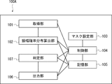
- FIG. 1 is a block diagram showing a configuration example of a first embodiment of an electromagnetic interference wave measuring apparatus according to the present invention.
- 1 includes at least an acquisition unit 101, an amplitude probability distribution calculation unit 102, a mask setting unit 103, a control unit 104, a storage unit 105, and an output unit 106. Is done.
- the acquisition unit 101 is an acquisition unit that measures and converts electromagnetic waves including disturbances such as electromagnetic interference waves into data.
- the reception interface used at this time may be a voltmeter, a field strength meter, a spectrum analyzer, or the like that can measure the amplitude for each frequency of electromagnetic waves.
- the acquisition unit 101 has a function of sampling over a predetermined time and repeating the measurement of the frequency and the amplitude value of the electromagnetic wave for each measurement position, and the electromagnetic interference wave emitted from the measurement target It has a function of converting the temporal waveform change into digital time-series measurement data.
- the converted time-series measurement data is sent to the amplitude probability distribution calculation unit 102 in such a manner that it can be classified at predetermined time intervals.
- the amplitude probability distribution calculation unit 102 is an amplitude probability distribution calculation unit that performs processing for calculating an amplitude probability distribution from time-series measurement data collected as measurement results in the acquisition unit 101.
- the amplitude probability distribution calculated by the amplitude probability distribution calculation unit 102 is sent to the output unit 106 and stored in the storage unit 105.
- the mask setting unit 103 is a mask setting unit that performs processing for converting the allowable bit error rate of the communication system desired by the user into an amplitude probability distribution mask according to the setting condition, and setting the converted amplitude probability distribution mask. is there.
- the amplitude probability distribution mask converted by the mask setting unit 103 is sent to the output unit 106 and stored in the storage unit 105.
- the setting condition of the mask setting unit 103 is determined by selecting a communication system or modulation scheme desired by the user and inputting an allowable bit error rate in the desired communication system or modulation scheme from the external input terminal by the user. It is desirable to be able to
- the allowable bit error rate in the communication system and the modulation system it is of course possible to use a fixed value determined in advance by a standard or the like instead of being input by the user.
- the bit error rate before error correction that can be viewed at a minimum is defined as 2 ⁇ 10 ⁇ 4 or less in a predetermined CN (Channel to Noise) ratio.
- the minimum receiver sensitivity at the error rate of 10 -3 or less is defined.
- the amplitude probability distribution mask itself which is a conversion result of the required bit error rate, is held in the storage unit 105 in advance, and the mask setting unit 103
- the amplitude probability distribution mask relating to the corresponding communication system is read from the storage unit 105 and set, thereby setting the amplitude probability distribution indicating the measurement result of the electromagnetic interference wave in the measurement target. It is desirable to have a configuration that can be presented simultaneously.
- the amplitude probability distribution mask Processing such as presenting an error to the effect that it is inappropriate to convert the message to the user and telling the user may be performed.
- the output unit 106 displays the amplitude probability distribution calculated based on the measurement result of the acquisition unit 101 in the amplitude probability distribution calculation unit 102 and the amplitude probability distribution mask set by conversion in the mask setting unit 103 in an internal display. Display on the device. Alternatively, the data is printed on a printer device and output to an external display device as necessary.
- the output method of the amplitude probability distribution and the amplitude probability distribution mask may be any method as long as the user can recognize it. For example, it may be output via a display device or a printer device.
- the amplitude probability distribution and the amplitude probability distribution mask stored in the storage unit 105 can be accessed from other information processing systems, so that they can be used in other information processing systems.
- the control unit 104 controls the acquisition unit 101, the amplitude probability distribution calculation unit 102, the mask setting unit 103, the storage unit 105, and the output unit 106, and enables the above-described functions performed by these units.
- the amplitude probability distribution mask set by the mask setting unit 103 is output to the storage unit 105 and the output unit 106 via the control unit 104.
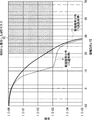
- FIG. 2 shows an output unit that receives the amplitude probability distribution calculated by the amplitude probability distribution calculating unit 102 and the amplitude probability distribution mask created by the mask setting unit 103 in the interference wave measuring apparatus according to the first embodiment of the present invention. It is an image figure which shows an example of the data which 106 displays, and arrange
- FIG. 2 illustrates an APD (Amplitude Probability Distribution) mask, that is, an amplitude probability distribution mask 10 calculated from the bit error rate (BER) allowed in the mobile radio communication terminal.
- APD Amplitude Probability Distribution
- the amplitude probability distribution mask 10 shown in the upper right part of FIG. 2 is set by converting from the allowable bit error rate (BER) in the communication system selected / input by the user, that is, the communication system using the mobile radio communication terminal. .
- BER allowable bit error rate
- the measurement result of the amplitude probability distribution and the setting result of the amplitude probability distribution mask are presented, so that the user can obtain the desired communication system in which the electromagnetic interference wave radiated from the measurement target is desired. It is possible to quickly and easily grasp how much the influence is below, and it can be effectively used for EMI countermeasures. In addition, since the user can estimate the bit error rate characteristics at the initial stage of electromagnetic interference measurement, it is possible to perform front loading for EMI design and development, and to reduce the product cost.
- the second embodiment of the present invention is an example in which the mask setting unit 103 in the electromagnetic interference measuring apparatus 100 shown in FIG.
- the mask setting unit 103 has a function of converting a desired allowable bit error rate into an amplitude probability distribution mask and setting the amplitude probability distribution mask.
- the second embodiment is characterized in that the mask setting unit 103 calculates amplitude probability distribution masks for a plurality of modulation schemes, and the output unit 106 outputs and displays amplitude probability distribution masks for the plurality of modulation schemes simultaneously. .
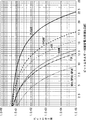
- FIG. 3 is a characteristic diagram showing the theoretical value of the bit error rate in each of the different modulation schemes when the interference wave is regarded as additive Gaussian noise, and the horizontal axis represents the bit energy to noise power density ratio (Eb / No).
- the graph shows the allowable bit error rate calculated theoretically for each modulation method with the bit error rate (BER) on the vertical axis.
- the bit error rate characteristic varies depending on the modulation method, and the allowable bit error rate is MSK (Minimum Shift Keying) / BPSK (Binary Phase Shift Keying) / QPSK (Quadrature Phase) at the same Eb / No. Shift Keying (FSK) modulation method, FSK (Frequency Shift Keying) modulation method, 16QAM (Quadrature Amplitude Modulation) modulation method, ASK (Amplitude-Shift Keying) modulation method, 64QAM modulation method, 256QAM modulation method, etc. Therefore, the amplitude probability distribution mask set by conversion from the allowable bit error rate also has a different shape according to the modulation method.
- MSK Minimum Shift Keying
- BPSK Binary Phase Shift Keying
- QPSK Quadrature Phase
- FSK Shift Keying
- FSK Frequency Shift Keying
- 16QAM Quadrature Amplitude Modulation
- a plurality of amplitude probability distribution masks corresponding to the plurality of modulation schemes may be presented. Can be useful.
- FIG. 4 shows an output unit that receives the amplitude probability distribution calculated by the amplitude probability distribution calculation unit 102 and the amplitude probability distribution mask created by the mask setting unit 103 in the interference wave measuring apparatus according to the second embodiment of the present invention.
- 106 is an image diagram showing an example of data displayed by 106, and similarly to the case of FIG. 2, the horizontal axis indicates amplitude and the vertical axis indicates probability.
- the image diagram of FIG. 4 shows that when the load of an IC (Integrated Circuit) serving as a disturbing wave source for the mobile radio communication terminal is normal as an amplitude probability distribution as a measurement result of the mobile radio communication terminal.
- IC Integrated Circuit
- An amplitude probability distribution 11 that is a measurement result when the IC is normal and an amplitude probability distribution 12 that is a measurement result when the load on the IC is high (when the IC is highly loaded) are illustrated.
- the amplitude probability distribution mask calculated from the bit error rate (BER: Bit Error Rate) allowed in the mobile radio communication terminal is different from the case of FIG. 2, and the image of FIG. 4 shows the mobile radio communication.
- a plurality of amplitude probability distribution masks in each modulation scheme adaptively used in the terminal are displayed simultaneously.
- the four amplitude probability distribution masks of the amplitude probability distribution mask 10C when used and the amplitude probability distribution mask 10D when the 256QAM modulation method is used are simultaneously displayed.
- the amplitude probability distribution mask shown in FIG. 4 is illustrated so that it is easy to understand how different amplitude probability distribution masks are displayed depending on the modulation method and operating environment, and the amplitude probability distribution mask in each actual modulation method. May be arranged differently from the case of FIG.
- the user can simultaneously evaluate the suitability of the permissible value for each modulation method, so that not only the EMI countermeasures but also the system control surface for selecting the modulation method Useful knowledge can be obtained.
- the third embodiment of the present invention is an example different from the second embodiment in which the mask setting unit 103 in the electromagnetic interference wave measuring apparatus 100 shown in FIG. 1 is preferably configured.
- the mask setting unit 103 has the function of converting a desired allowable bit error rate into an amplitude probability distribution mask and setting the amplitude probability distribution mask, as in the first and second embodiments described above.
- the mask setting unit 103 calculates an amplitude probability distribution mask to be set by conversion from the theoretical value of the bit error rate in additive Gaussian noise, and the output unit 106 converts the amplitude probability distribution mask.
- the amplitude probability distribution mask set in this way is output and displayed.
- the amplitude probability distribution mask set by converting from the bit error rate of the Gaussian noise having no frequency dependence, not the compatibility with the bit error rate allowable value of the interference wave is used as the electromagnetic interference. It can be used as a reference when measuring waves.
- the theoretical calculation value of the bit error rate in additive Gaussian noise is known in various modulation schemes.
- the interference wave characteristic actually radiated from the measurement target is generally non-Gaussian noise having frequency dependence.
- the disturbing wave characteristic is impulse-like, the bit error rate is often significantly deteriorated as compared with Gaussian noise of the same power.
- the user can influence the influence of interference waves generated from the measurement target on communication when additive Gaussian noise occurs. It is possible to easily determine how much the value is.
- the fourth embodiment is characterized by having a determination unit that compares the magnitude relationship between the amplitude probability distribution mask converted and set by the mask setting unit and the amplitude probability distribution of the measured interference wave.
- FIG. 5 is a block diagram showing a configuration example of the fourth embodiment of the electromagnetic interference measuring apparatus according to the present invention.
- the electromagnetic interference wave measuring device 100A shown in FIG. 5 has a configuration in which a determination unit 107 is further added to the electromagnetic interference wave measuring device 100 shown in FIG. 1 of the first embodiment.
- the functional unit has the same function as each functional unit of the electromagnetic interference wave measuring apparatus 100 of FIG. 1, and redundant description here is omitted.
- the determination unit 107 converts the amplitude probability distribution of the electromagnetic interference wave converted by the amplitude probability distribution calculation unit 102 based on the time-series measurement data related to the electromagnetic interference wave acquired by the acquisition unit 101 and the mask setting unit 103. The magnitude relationship with the set amplitude probability distribution mask is determined. As a determination result, when the amplitude probability distribution of the electromagnetic interference wave overlaps with the amplitude probability distribution mask, that is, the measured value of the amplitude probability distribution that is the measurement result of the electromagnetic interference wave is larger than the mask value of the amplitude probability distribution mask indicating the allowable range. In the case where the error has also increased, the determination unit 107 sends alarm information indicating that an error caused by electromagnetic interference has occurred to the output unit 106.
- the output unit 106 outputs the amplitude probability distribution calculated as the measurement result by the amplitude probability distribution calculation unit 102 and the amplitude probability distribution mask calculated by the mask setting unit 103 based on the allowable bit error rate. Further, alarm information indicating the presence or absence of the error (the measured value of the amplitude probability distribution has become larger than the mask value of the amplitude probability distribution mask) as the determination result of the determination unit 107 is output.
- the determination of the suitability of the electromagnetic interference wave with respect to the amplitude probability distribution mask can be automated based on the determination result of the determination unit 107. Based on the alarm information output from the output unit 106, the user can easily recognize the presence or absence of an error in the actual measurement result (amplitude probability distribution) for the amplitude probability distribution mask.
- the determination unit 107 differs from the above-described operation in which a determination result indicating whether or not an error has occurred, that is, alarm information is sent to the output unit 106, and the following trigger signal is sent to the output unit 106. You may make it perform the operation
- the determination unit 107 outputs the amplitude probability distribution and the amplitude probability distribution mask (in addition, the case only when it is determined that an error in the actual measurement result (amplitude probability distribution) with respect to the amplitude probability distribution mask has occurred. Depending on the situation, a trigger signal for prompting the user to output error information indicating the occurrence of an error is sent to the output unit 106. If the determination unit 107 determines that no error has occurred, the output unit 106 outputs and displays the amplitude probability distribution and the amplitude probability distribution mask without sending the trigger signal to the output unit 106. It is good also as a structure which does not.
- the output unit 106 only when an electromagnetic interference wave whose amplitude probability distribution causes an error is captured with respect to the amplitude probability distribution mask, the output unit 106 at least displays the amplitude probability distribution of the measurement result and the amplitude probability indicating the allowable range.
- the distribution mask is output and displayed.
- Each functional part of the electromagnetic interference wave measuring apparatus 100 in FIG. 1 and the electromagnetic interference wave measuring apparatus 100A in FIG. 5 described above may be configured only by hardware as means for realizing each corresponding function, or electromagnetic As the interference wave measuring method, each function as described above may be realized using any realization means, or may be realized using a combination of hardware and software.
- a control program used for interference wave measurement is developed on a RAM (Random Access Memory) which is a program storage device, and control is performed based on the operation of the control program.
- RAM Random Access Memory
- By operating hardware such as a unit (CPU: Central Processing Unit), various processing units (processing steps) corresponding to each functional unit are realized.
- Non-transitory computer readable media include various types of tangible storage media.
- Examples of non-transitory computer-readable media include magnetic recording media (eg, flexible disks, magnetic tapes, hard disk drives), magneto-optical recording media (eg, magneto-optical disks), CD-ROM (Read Only Memory) CD-R, CD -R / W, including semiconductor memory (for example, mask ROM, PROM (Programmable ROM), EPROM (Erasable PROM), flash ROM, RAM (Random Access Memory)).
- the program may be supplied to the computer by various types of temporary computer readable media.
- Examples of transitory computer readable media include electrical signals, optical signals, and electromagnetic waves.
- the temporary computer-readable medium can supply the program to the computer via a wired communication path such as an electric wire and an optical fiber, or a wireless communication path.
- a program is supplied to the computer, the program is read into a memory (RAM) that is a program storage device, and the control unit and the like are operated.
- RAM memory
- an information processing system that operates as an electromagnetic interference wave measuring device is based on an electromagnetic interference wave measurement program developed on a RAM, an acquisition step corresponding to the function of the acquisition unit 101, and an amplitude Corresponding to the amplitude probability distribution calculating step corresponding to the function of the probability distribution calculating unit 102, the mask setting step corresponding to the function of the mask setting unit 103, the determining step corresponding to the function of the determining unit 107, and the function of the output unit 106 It is possible to realize this by executing each processing step such as an output step, and so on, and operating the control unit.
- Such an information processing system can be constructed on a personal computer alone, a server, or a cloud.
- the present invention can be suitably applied to a measuring apparatus that estimates the influence of electromagnetic interference on a wireless communication system in measurement evaluation and environmental compatibility testing of interference emitted from general electronic equipment such as home appliances. .
- knowledge for efficiently implementing EMI countermeasures can be obtained.
Landscapes
- Physics & Mathematics (AREA)
- Electromagnetism (AREA)
- General Physics & Mathematics (AREA)
- Monitoring And Testing Of Transmission In General (AREA)
- Mobile Radio Communication Systems (AREA)
Abstract
Description

本発明は、前述のような課題に鑑みて成されたものであり、被測定対象から放出される電磁妨害波が所望の通信システムに与える影響を精度良く判断することを可能にする電磁妨害波測定装置、電磁妨害波測定方法および電磁妨害波測定プログラムを提供することを、その目的としている。
被測定対象から放出される電磁妨害波を測定し、電磁干渉の評価を行う電磁妨害波測定装置であって、
任意に指定された所望の通信システムにおいて許容されるビットエラー率を振幅確率分布マスクに変換し、変換した前記振幅確率分布マスクを設定するマスク設定部と、
前記被測定対象から放出されている電磁妨害波に関する時系列の測定データを収集する取得部と、
前記取得部において収集されたあらかじめ定めた所定時間毎の前記測定データに基づいて、前記電磁妨害波に関する振幅確率分布を算出する振幅確率分布算出部と、
前記マスク設定部において設定された前記振幅確率分布マスク、および前記振幅確率分布算出部において算出された前記振幅確率分布を出力する出力部と
を有することを特徴とする。
被測定対象から放出される電磁妨害波を測定し、電磁干渉の評価を行う電磁妨害波測定方法であって、
任意に指定された所望の通信システムにおいて許容されるビットエラー率を振幅確率分布マスクに変換し、変換した前記振幅確率分布マスクを設定するマスク設定ステップと、
前記被測定対象から放出されている電磁妨害波に関する時系列の測定データを収集する取得ステップと、
前記取得ステップにおいて収集されたあらかじめ定めた所定時間毎の前記測定データに基づいて、測定結果を示す振幅確率分布を算出する振幅確率分布測定ステップと、
前記マスク設定ステップにおいて設定された前記振幅確率分布マスクおよび前記振幅確率分布測定ステップにおいて算出された前記振幅確率分布を出力する出力ステップと
を有することを特徴とする。
本発明の実施形態の説明に先立って、本発明の特徴についてその概要をまず説明する。本発明は、通信性能の許容値から算出した振幅確率分布マスクを表示する機能を備えることにより、被測定対象から放出される電磁妨害波が所望の通信システムに与える影響を精度良く判断することを可能にすることを主要な特徴としている。而して、測定者(ユーザ)は、所望の通信システムに関する通信性能値の観点から、被測定対象から放出されている電磁妨害波が許容されるものか否かを直ちに判断することができ、対策を素早く実施することができる。さらには、電子機器におけるフロントローディング設計開発や通信性能を保障する高品質な無線通信機器の設計開発等も可能になる。
次に、本発明に係る電磁妨害波測定装置の実施形態について、図面を参照して詳細に説明する。なお、以下の各図面に付した符号は、理解を助けるための一例として各要素に便宜上付記したものであり、本発明を図示の態様に限定することを意図するものではないことは言うまでもない。
まず、本発明の第1実施形態として、通信性能として許容されるビットエラー率から変換した振幅確率分布マスクを提示する機能を有する電磁妨害波測定装置の好適な構成例について、図1を用いて説明する。図1は、本発明に係る電磁妨害波測定装置の第1実施形態の構成例を示すブロック構成図である。
次に、本発明の第2実施形態は、図1に示した電磁妨害波測定装置100におけるマスク設定部103をさらに好適に構成した例である。第1実施形態の説明で述べたとおり、マスク設定部103は、所望の許容ビットエラー率を振幅確率分布マスクに変換し、この振幅確率分布マスクを設定する機能を有する。本第2実施形態は、マスク設定部103において、複数の変調方式における振幅確率分布マスクを算出し、出力部106において、複数の変調方式における振幅確率分布マスクを同時に出力表示することを特徴としている。
次に、本発明の第3実施形態は、図1に示した電磁妨害波測定装置100におけるマスク設定部103を好適に構成した、第2の実施形態とは異なる例である。マスク設定部103が、所望の許容ビットエラー率を振幅確率分布マスクに変換し、この振幅確率分布マスクを設定する機能を有することは、前述の第1および第2実施形態と同じである。本第3実施形態は、マスク設定部103において、加法性ガウス雑音におけるビットエラー率理論値から変換して設定すべき振幅確率分布マスクを算出し、出力部106において、マスク設定部103にて変換して設定された振幅確率分布マスクを出力表示することを特徴としている。つまり、本第3実施形態においては、妨害波のビットエラー率許容値に対する適合性ではなく、周波数依存性がないガウス雑音のビットエラー率から変換して設定された振幅確率分布マスクを、電磁妨害波測定時の参照として用いることを可能にしている。
次に、本発明の振幅確率分布マスクを表示する機能を有する妨害波測定装置の第4実施形態として、図1に示した電磁妨害波測定装置100とは異なる構成からなる電磁妨害波測定装置の好適な構成例について説明する。本第4実施形態においては、マスク設定部において変換して設定された振幅確率分布マスクと、測定した妨害波の振幅確率分布との大小関係を比較する判定部を有することを特徴としている。
前述した図1の電磁妨害波測定装置100や図5の電磁妨害波測定装置100Aの各機能部は、該当する各機能を実現する手段としてハードウェアのみにより構成しても良いし、あるいは、電磁妨害波測定方法として、かくのごときそれぞれの機能を如何なる実現手段を用いて実現するようにしても良いし、あるいは、ハードウェアとソフトウェアとの組み合わせを用いて実現しても良い。ハードウェアとソフトウェアとを組み合わせた形態によって実現する場合には、プログラム記憶装置であるRAM(Random Access Memory)上に妨害波測定に供する制御プログラムが展開され、該制御プログラムの動作に基づいて、制御部(CPU:Central Processing Unit)等のハードウェアを動作させることによって、各機能部に相当する各種処理部(処理ステップ)として実現する。
10A 振幅確率分布マスク(MSK/BPSK/QPSK変調方式)
10B 振幅確率分布マスク(16QAM変調方式)
10C 振幅確率分布マスク(64QAM変調方式)
10D 振幅確率分布マスク(256QAM変調方式)
11 振幅確率分布(IC通常時)
12 振幅確率分布(IC高負荷時)
100 電磁妨害波測定装置
100A 電磁妨害波測定装置
101 取得部(取得手段)
102 振幅確率分布算出部(振幅確率分布測定手段)
103 マスク設定部(マスク設定手段)
104 制御部(制御手段)
105 記憶部(記憶手段)
106 出力部(出力手段)
107 判定部(判定手段)
Claims (10)
- 被測定対象から放出される電磁妨害波を測定し、電磁干渉の評価を行う電磁妨害波測定装置において、
任意に指定された所望の通信システムにおいて許容されるビットエラー率を振幅確率分布マスクに変換し、変換した前記振幅確率分布マスクを設定するマスク設定手段と、
前記被測定対象から放出されている電磁妨害波に関する時系列の測定データを収集する取得手段と、
前記取得手段において収集されたあらかじめ定めた所定時間毎の前記測定データに基づいて、前記電磁妨害波に関する振幅確率分布を算出する振幅確率分布算出手段と、
前記マスク設定手段において設定された前記振幅確率分布マスク、および前記振幅確率分布算出手段において算出された前記振幅確率分布を出力する出力手段と
を有する電磁妨害波測定装置。 - 前記マスク設定手段が設定する前記振幅確率分布マスクは、1ないし複数個の異なる変調方式のビットエラー率をそれぞれ変換して得た1ないし複数個の振幅確率分布マスクであることを特徴とする請求項1に記載の電磁妨害波測定装置。
- 前記マスク設定手段が前記振幅確率分布マスクに変換する前記ビットエラー率は、前記被測定対象から放出されている電磁妨害波が加法性ガウス雑音であると仮定した場合の理論ビットエラー率であることを特徴とする請求項1に記載の電磁妨害波測定装置。
- 前記振幅確率分布算出手段において算出された前記振幅確率分布と、前記マスク設定手段において設定された前記振幅確率分布マスクとの大小関係の判定を行い、この判定に基づき前記振幅確率分布マスクに対するエラーの有無を示すアラーム情報を前記出力手段に送出する判定手段をさらに有し、
前記出力手段は、前記判定手段から受け取った前記アラーム情報をさらに出力することを特徴とする請求項1ないし3のいずれか1項に記載の電磁妨害波測定装置。 - 前記判定手段は、前記エラーが発生していると判定した場合には、前記振幅確率分布マスクと前記振幅確率分布との出力を促すためのトリガ信号を、前記アラーム情報に代えて、前記出力手段に送出することを特徴とする請求項4に記載の電磁妨害波測定装置。
- 被測定対象から放出される電磁妨害波を測定し、電磁干渉の評価を行う電磁妨害波測定方法において、
任意に指定された所望の通信システムにおいて許容されるビットエラー率を振幅確率分布マスクに変換し、変換した前記振幅確率分布マスクを設定し、
前記被測定対象から放出されている電磁妨害波に関する時系列の測定データを収集し、
収集されたあらかじめ定めた所定時間毎の前記測定データに基づいて、測定結果を示す振幅確率分布を算出し、
設定された前記振幅確率分布マスクおよび算出された前記振幅確率分布を出力する
電磁妨害波測定方法。 - 設定する前記振幅確率分布マスクは、1ないし複数個の異なる変調方式のビットエラー率をそれぞれ変換して得た1ないし複数個の振幅確率分布マスクであることを特徴とする請求項6に記載の電磁妨害波測定方法。
- 前記振幅確率分布マスクに変換する前記ビットエラー率は、前記被測定対象から放出されている電磁妨害波が加法性ガウス雑音であると仮定した場合の理論ビットエラー率であることを特徴とする請求項6に記載の電磁妨害波測定方法。
- 算出された前記振幅確率分布と、設定された前記振幅確率分布マスクとの大小関係の判定を行い、この判定に基づき前記振幅確率分布マスクに対するエラーの有無を示すアラーム情報を送出することをさらに有し、
前記振幅確率分布を出力すると共に、送出された前記アラーム情報をさらに出力することを特徴とする請求項6ないし8のいずれか1項に記載の電磁妨害波測定方法。 - 請求項6ないし9のいずれか1項に記載の電磁妨害波測定方法を、コンピュータによって実行せしめる電磁妨害波測定プログラムが格納された非一時的なコンピュータ可読媒体。
Priority Applications (2)
| Application Number | Priority Date | Filing Date | Title |
|---|---|---|---|
| JP2015547378A JPWO2015072045A1 (ja) | 2013-11-14 | 2014-06-10 | 電磁妨害波測定装置、電磁妨害波測定方法および非一時的なコンピュータ可読媒体 |
| US15/035,534 US20160299182A1 (en) | 2013-11-14 | 2014-06-10 | Electromagnetic interference wave measurement device, electromagnetic interference wave measurement method and non-transitory computer-readable medium |
Applications Claiming Priority (2)
| Application Number | Priority Date | Filing Date | Title |
|---|---|---|---|
| JP2013235651 | 2013-11-14 | ||
| JP2013-235651 | 2013-11-14 |
Publications (1)
| Publication Number | Publication Date |
|---|---|
| WO2015072045A1 true WO2015072045A1 (ja) | 2015-05-21 |
Family
ID=53057003
Family Applications (1)
| Application Number | Title | Priority Date | Filing Date |
|---|---|---|---|
| PCT/JP2014/003075 Ceased WO2015072045A1 (ja) | 2013-11-14 | 2014-06-10 | 電磁妨害波測定装置、電磁妨害波測定方法および非一時的なコンピュータ可読媒体 |
Country Status (3)
| Country | Link |
|---|---|
| US (1) | US20160299182A1 (ja) |
| JP (1) | JPWO2015072045A1 (ja) |
| WO (1) | WO2015072045A1 (ja) |
Cited By (3)
| Publication number | Priority date | Publication date | Assignee | Title |
|---|---|---|---|---|
| CN110554246A (zh) * | 2018-06-01 | 2019-12-10 | 三星电子株式会社 | 电磁传感器和包括该电磁传感器的移动设备 |
| JPWO2021176805A1 (ja) * | 2020-03-02 | 2021-09-10 | ||
| CN116558423A (zh) * | 2023-05-25 | 2023-08-08 | 中国科学院长春光学精密机械与物理研究所 | 一种计量用莫尔条纹抗电磁干扰方法 |
Families Citing this family (3)
| Publication number | Priority date | Publication date | Assignee | Title |
|---|---|---|---|---|
| US11320831B2 (en) * | 2018-01-23 | 2022-05-03 | Panasonic Intellectual Property Management Co., Ltd. | Mover, mover control system, method of detecting object by mover, moving system, and method of controlling mover |
| US11012862B2 (en) * | 2019-01-26 | 2021-05-18 | Oracle International Corporation | Camouflaging EMI fingerprints in enterprise computer systems to enhance system security |
| US12107673B2 (en) * | 2021-09-07 | 2024-10-01 | Qualcomm Incorporated | Jammer detection system |
Family Cites Families (4)
| Publication number | Priority date | Publication date | Assignee | Title |
|---|---|---|---|---|
| JP3586348B2 (ja) * | 1997-03-05 | 2004-11-10 | 富士通株式会社 | 信号対干渉電力比測定装置及び信号対干渉電力比測定方法並びにcdma通信方式下での送信電力制御方法 |
| JP3740942B2 (ja) * | 2000-04-18 | 2006-02-01 | 富士ゼロックス株式会社 | 電磁波ノイズ測定装置、方法、及び記録媒体 |
| EP1854237A2 (en) * | 2005-02-25 | 2007-11-14 | Lecroy Corporation | Measuring components of jitter |
| WO2009041542A1 (ja) * | 2007-09-28 | 2009-04-02 | Kyocera Corporation | 無線通信装置及び受信品質推定方法 |
-
2014
- 2014-06-10 US US15/035,534 patent/US20160299182A1/en not_active Abandoned
- 2014-06-10 JP JP2015547378A patent/JPWO2015072045A1/ja active Pending
- 2014-06-10 WO PCT/JP2014/003075 patent/WO2015072045A1/ja not_active Ceased
Non-Patent Citations (1)
| Title |
|---|
| KAORU GOTO ET AL.: "Bogai Denjiha no Shinpuku Kakuritsu Bunpu Sokutei to Digital Musen Tsushin no Hogo", REVIEW OF THE NATIONAL INSTITUTE OF INFORMATION AND COMMUNICATIONS TECHNOLOGY, vol. 52, no. 1, March 2006 (2006-03-01), pages 6 9 - 77 * |
Cited By (5)
| Publication number | Priority date | Publication date | Assignee | Title |
|---|---|---|---|---|
| CN110554246A (zh) * | 2018-06-01 | 2019-12-10 | 三星电子株式会社 | 电磁传感器和包括该电磁传感器的移动设备 |
| CN110554246B (zh) * | 2018-06-01 | 2024-06-07 | 三星电子株式会社 | 电磁传感器和包括该电磁传感器的移动设备 |
| JPWO2021176805A1 (ja) * | 2020-03-02 | 2021-09-10 | ||
| JP7435732B2 (ja) | 2020-03-02 | 2024-02-21 | 日本電気株式会社 | 異常検知装置、異常検知方法及びプログラム |
| CN116558423A (zh) * | 2023-05-25 | 2023-08-08 | 中国科学院长春光学精密机械与物理研究所 | 一种计量用莫尔条纹抗电磁干扰方法 |
Also Published As
| Publication number | Publication date |
|---|---|
| JPWO2015072045A1 (ja) | 2017-03-16 |
| US20160299182A1 (en) | 2016-10-13 |
Similar Documents
| Publication | Publication Date | Title |
|---|---|---|
| WO2015072045A1 (ja) | 電磁妨害波測定装置、電磁妨害波測定方法および非一時的なコンピュータ可読媒体 | |
| US10404368B2 (en) | Method and apparatus for the detection of distortion or corruption of cellular communication signals | |
| JP6835582B2 (ja) | 電磁妨害波測定装置、電磁妨害波測定方法、および電磁妨害波測定プログラム | |
| EP3369182B1 (en) | Cell site passive intermodulation detection receiver | |
| JP5499687B2 (ja) | Ofdm無線通信端末 | |
| US20090262688A1 (en) | Rate adaptation methods for wireless communication apparatus, and wireless communication apparatus for performing wireless communication with rate adaptation | |
| Althunibat et al. | Performance optimisation of soft and hard spectrum sensing schemes in cognitive radio | |
| JP6339227B2 (ja) | セル干渉の調査方法及びシステム、ネットワークマネージャ | |
| JP2008039762A (ja) | 電磁妨害波測定システムと、それを用いた選別システム | |
| JP2017026496A (ja) | 放射イミュニティ試験装置およびその方法 | |
| Zhang et al. | Measurements and statistical analyses of electromagnetic noise for industrial wireless communications | |
| JP2011211514A (ja) | 故障予測装置、故障予測方法、電磁干渉検出装置、電磁干渉検出方法、及び制御プログラム | |
| JP6943063B2 (ja) | 管理装置、無線通信システムおよび管理方法 | |
| AU2016307395B2 (en) | Methods for analysing frequency resources and selecting transmission frequency in a wireless communication system | |
| KR102707635B1 (ko) | 오류 벡터 크기의 오버 디 에어 측정들 | |
| CN110149160B (zh) | 一种用于td-lte干扰检测的方法、系统和存储介质 | |
| JP6118217B2 (ja) | 無線受信装置及びアンテナ選択方法 | |
| JP5173490B2 (ja) | 感度劣化推定システム及び感度劣化推定方法 | |
| CN106686625B (zh) | 一种检测邻区干扰的方法及基站 | |
| US10219167B2 (en) | Antenna array uplink sector level sweep to allow coexistence with other in-device radios | |
| US9693360B2 (en) | Methods, computer programs, network node and transceiver device | |
| JP5942804B2 (ja) | 無線監視装置 | |
| US20250044352A1 (en) | Use of a data symbol error boundary violation as a trigger source for signal capture and storage | |
| US12323185B2 (en) | Method for determining actual values of one or more characteristics of a phase-modulated optical signal | |
| Ruiz | TREBALL DE FI DE GRAU |
Legal Events
| Date | Code | Title | Description |
|---|---|---|---|
| 121 | Ep: the epo has been informed by wipo that ep was designated in this application |
Ref document number: 14861515 Country of ref document: EP Kind code of ref document: A1 |
|
| ENP | Entry into the national phase |
Ref document number: 2015547378 Country of ref document: JP Kind code of ref document: A |
|
| WWE | Wipo information: entry into national phase |
Ref document number: 15035534 Country of ref document: US |
|
| NENP | Non-entry into the national phase |
Ref country code: DE |
|
| 122 | Ep: pct application non-entry in european phase |
Ref document number: 14861515 Country of ref document: EP Kind code of ref document: A1 |