WO2015068758A1 - 医療用具及び光線治療装置 - Google Patents
医療用具及び光線治療装置 Download PDFInfo
- Publication number
- WO2015068758A1 WO2015068758A1 PCT/JP2014/079420 JP2014079420W WO2015068758A1 WO 2015068758 A1 WO2015068758 A1 WO 2015068758A1 JP 2014079420 W JP2014079420 W JP 2014079420W WO 2015068758 A1 WO2015068758 A1 WO 2015068758A1
- Authority
- WO
- WIPO (PCT)
- Prior art keywords
- light
- medical device
- irradiation
- light diffuser
- diffuser
- Prior art date
- Legal status (The legal status is an assumption and is not a legal conclusion. Google has not performed a legal analysis and makes no representation as to the accuracy of the status listed.)
- Ceased
Links
Images


Classifications
-
- A—HUMAN NECESSITIES
- A61—MEDICAL OR VETERINARY SCIENCE; HYGIENE
- A61N—ELECTROTHERAPY; MAGNETOTHERAPY; RADIATION THERAPY; ULTRASOUND THERAPY
- A61N5/00—Radiation therapy
- A61N5/06—Radiation therapy using light
- A61N5/0613—Apparatus adapted for a specific treatment
- A61N5/062—Photodynamic therapy, i.e. excitation of an agent
-
- A—HUMAN NECESSITIES
- A61—MEDICAL OR VETERINARY SCIENCE; HYGIENE
- A61N—ELECTROTHERAPY; MAGNETOTHERAPY; RADIATION THERAPY; ULTRASOUND THERAPY
- A61N5/00—Radiation therapy
- A61N5/06—Radiation therapy using light
- A61N5/0601—Apparatus for use inside the body
-
- A—HUMAN NECESSITIES
- A61—MEDICAL OR VETERINARY SCIENCE; HYGIENE
- A61N—ELECTROTHERAPY; MAGNETOTHERAPY; RADIATION THERAPY; ULTRASOUND THERAPY
- A61N5/00—Radiation therapy
- A61N5/06—Radiation therapy using light
- A61N5/0601—Apparatus for use inside the body
- A61N5/0603—Apparatus for use inside the body for treatment of body cavities
-
- A—HUMAN NECESSITIES
- A61—MEDICAL OR VETERINARY SCIENCE; HYGIENE
- A61N—ELECTROTHERAPY; MAGNETOTHERAPY; RADIATION THERAPY; ULTRASOUND THERAPY
- A61N5/00—Radiation therapy
- A61N5/06—Radiation therapy using light
- A61N5/067—Radiation therapy using light using laser light
-
- A—HUMAN NECESSITIES
- A61—MEDICAL OR VETERINARY SCIENCE; HYGIENE
- A61B—DIAGNOSIS; SURGERY; IDENTIFICATION
- A61B18/00—Surgical instruments, devices or methods for transferring non-mechanical forms of energy to or from the body
- A61B2018/00636—Sensing and controlling the application of energy
- A61B2018/00773—Sensed parameters
- A61B2018/00839—Bioelectrical parameters, e.g. ECG, EEG
-
- A—HUMAN NECESSITIES
- A61—MEDICAL OR VETERINARY SCIENCE; HYGIENE
- A61B—DIAGNOSIS; SURGERY; IDENTIFICATION
- A61B18/00—Surgical instruments, devices or methods for transferring non-mechanical forms of energy to or from the body
- A61B18/18—Surgical instruments, devices or methods for transferring non-mechanical forms of energy to or from the body by applying electromagnetic radiation, e.g. microwaves
- A61B18/20—Surgical instruments, devices or methods for transferring non-mechanical forms of energy to or from the body by applying electromagnetic radiation, e.g. microwaves using laser
- A61B18/22—Surgical instruments, devices or methods for transferring non-mechanical forms of energy to or from the body by applying electromagnetic radiation, e.g. microwaves using laser the beam being directed along or through a flexible conduit, e.g. an optical fibre; Couplings or hand-pieces therefor
- A61B2018/2255—Optical elements at the distal end of probe tips
- A61B2018/2261—Optical elements at the distal end of probe tips with scattering, diffusion or dispersion of light
-
- A—HUMAN NECESSITIES
- A61—MEDICAL OR VETERINARY SCIENCE; HYGIENE
- A61N—ELECTROTHERAPY; MAGNETOTHERAPY; RADIATION THERAPY; ULTRASOUND THERAPY
- A61N5/00—Radiation therapy
- A61N5/06—Radiation therapy using light
- A61N5/0601—Apparatus for use inside the body
- A61N2005/0602—Apparatus for use inside the body for treatment of blood vessels
-
- A—HUMAN NECESSITIES
- A61—MEDICAL OR VETERINARY SCIENCE; HYGIENE
- A61N—ELECTROTHERAPY; MAGNETOTHERAPY; RADIATION THERAPY; ULTRASOUND THERAPY
- A61N5/00—Radiation therapy
- A61N5/06—Radiation therapy using light
- A61N2005/063—Radiation therapy using light comprising light transmitting means, e.g. optical fibres
-
- A—HUMAN NECESSITIES
- A61—MEDICAL OR VETERINARY SCIENCE; HYGIENE
- A61N—ELECTROTHERAPY; MAGNETOTHERAPY; RADIATION THERAPY; ULTRASOUND THERAPY
- A61N5/00—Radiation therapy
- A61N5/06—Radiation therapy using light
- A61N2005/0658—Radiation therapy using light characterised by the wavelength of light used
- A61N2005/0659—Radiation therapy using light characterised by the wavelength of light used infrared
-
- A—HUMAN NECESSITIES
- A61—MEDICAL OR VETERINARY SCIENCE; HYGIENE
- A61N—ELECTROTHERAPY; MAGNETOTHERAPY; RADIATION THERAPY; ULTRASOUND THERAPY
- A61N5/00—Radiation therapy
- A61N5/06—Radiation therapy using light
- A61N2005/0658—Radiation therapy using light characterised by the wavelength of light used
- A61N2005/0662—Visible light
Definitions
- the present invention relates to a medical device that includes a light diffuser that emits light to a treatment target, and that is used by being inserted into a living body, and a light treatment apparatus that includes the medical device.
- Tachyarrhythmias are arrhythmias that occur due to the transfer of aberrant excitation to normal myocardial tissue, or due to the formation of a circling circuit (reentry circuit) of electrical excitation within myocardial tissue.
- the heart's excitation is controlled at a normal rate (sinus rhythm) by the excitation from the sinus node, but in the case of tachyarrhythmia, the heart beat is faster than the sinus rhythm due to abnormal excitation from some heart tissues Persist at a rate.
- the reentry circuit refers to a portion in which excitation is circling like a circuit without normal electrical excitation transmission due to the presence of a transmission failure site in myocardial tissue.
- a photosensitizer is administered by a method such as intravenous injection, and in a state in which the photosensitizer is distributed to the target tissue, a light beam such as a laser beam is irradiated, and the photosensitizer and light, oxygen are delivered.
- the photosensitization reaction is caused by this, and the treatment of this photosensitization reaction is carried out by necrosis of the cells of the target tissue.
- a laser treatment system for performing photodynamic treatment one comprising a laser catheter and a PDT device main body for emitting laser light to the laser catheter and detecting return light from the laser catheter is known (for example, Patent Document 1) ).
- the laser catheter of Patent Document 1 includes an optical fiber incorporated along the extension direction of the catheter tube, and an optical window provided in optical continuity with the tip of the optical fiber at the outermost part of the distal end of the catheter tube; Be equipped with.
- the optical window transmits illumination light emitted from the tip of the optical fiber, and condenses the fluorescence emitted by the PDT agent on the tip of the optical fiber. Since the laser catheter of Patent Document 1 is configured as described above, photodynamic treatment can be performed by bringing the tip of the laser catheter into contact with the tissue to be treated.
- the laser catheter of Patent Document 1 is configured to irradiate the laser from the tip of the catheter tube, similarly to the catheter for radio frequency ablation. Therefore, when treating arrhythmia using the laser catheter of Patent Document 1, as in the case of radio frequency catheter ablation, irradiation is performed point by point, and in order to set a line for blocking an abnormal electrical signal, too It is necessary to connect the points.
- the laser catheter of Patent Document 1 is limited in the range in which laser irradiation can be performed, and in order to create an abnormal electric conduction blocking line, it was necessary to shift the irradiation range sequentially to obtain a linear treatment area.
- a hand-held excision device used to treat arrhythmia by forming a conduction block around a pulmonary vein one that forms a photoablation injury with infrared radiation or the like is known (for example, patent documents 2).
- the excision device of Patent Document 2 is an epicardial application performed during a surgical procedure for opening a patient's chest cavity, and an endocardial application performed during a valve replacement procedure for opening a chest to expose a myocardium.
- a light diffuser that is used and extends along the length of the tip is provided inside the looped tip. According to the excision device of Patent Document 2, a linear injury corresponding to the length of the light diffuser can be formed, and the abnormal electric conduction cutoff line can be formed more easily.
- JP 2012-147937 A Japanese Patent Application Publication No. 2008-501441
- an electrophysiological test is performed to determine the transmission path of the electrical signal and a treatment for blocking the path is performed at once. Since this is a fully monitored operation with electrophysiological examinations and immediate treatment decisions, there is a need to achieve electrical conduction block of myocardial tissue by immediate treatment.
- the practitioner can obtain information on the extent to which the light irradiation from the laser inflicts the tissue from time to time. There is no way to know in real time, which has been a barrier to photodynamic therapy clinicalization in the treatment of arrhythmias.
- the present invention has been made in view of the above problems, and an object of the present invention is a medical device for irradiating light to a treatment target site, and by providing an irradiation range capable of covering the entire treatment target site.
- An object of the present invention is to provide a medical device and a light treatment apparatus capable of treating the entire treatment target site by one-time irradiation.
- Another object of the present invention is to provide a medical device and a phototherapy apparatus capable of performing photodynamic therapy and measurement of the progress of photodynamic therapy with a single device.
- Another object of the present invention is to provide a medical device and a phototherapy device having an irradiation area capable of covering the entire abnormal electric conduction blocking line of arrhythmia and capable of forming the abnormal electric conduction blocking line by one irradiation. .
- the subject is a medical device which is inserted into a living body and irradiates light to a treatment target site to treat the site, and has a long medical treatment having at least one lumen.
- a device main body an elongated light diffuser for irradiating light to the tissue to be treated, which is inserted into the medical device main body so as to extend along the longitudinal direction of the medical device main body;
- a long light receiving light diffuser for receiving light from a tissue to be treated, and a long reflector provided with a reflecting surface for reflecting light, wherein the medical device body is provided on at least a part of the outer wall
- An optically transparent transparent outer wall extending along the longitudinal direction, the light diffusing body receiving light from the tissue to be treated and irradiating means for irradiating the tissue to be treated with light;
- a light receiving means and sandwiched between the reflective surface and the transparent outer wall portion In position, that are arranged to face the reflective surface and the transparent outer wall, it is solved by.
- a long light having an irradiation unit for irradiating light to the treatment target tissue extending along the longitudinal direction of the medical device main body and a light receiving unit for receiving light from the treatment target tissue in the medical device main body Since the diffuser and the long reflector are provided, light can be irradiated to the long range, and a wide irradiation range can be secured. Therefore, there is no need for the practitioner to repeat irradiation and movement of the medical device in order to irradiate the entire treatment target site, and a single irradiation process enables a wide range of treatment, enabling rapid treatment. .
- the present invention can be suitably applied to photodynamic treatment of an arrhythmia which needs to locate a transmission path of an electrical signal and perform treatment for blocking the path at a stretch.
- the medical tool is also provided with light receiving means, it is possible to simultaneously monitor the progress of the treatment and monitor the operation status of the treatment apparatus regarding whether or not the irradiation is properly performed as set.
- the present inventors have found through research that they can monitor the degree of progress of photodynamic therapy by measuring fluorescence when irradiated with excitation light, and according to this finding and the present invention
- the measurement value of the return fluorescence received by the light diffuser makes it possible to monitor in real time the degree of progress of the photodynamic treatment.
- the irradiating means and the light receiving means are disposed opposite to the reflecting surface and the transparent outer wall at a position sandwiched between the reflecting surface and the transparent outer wall, the light irradiating by the irradiating means is suitable by the reflecting surface. While being able to concentrate on a certain site, it is possible to efficiently receive fluorescence when light is irradiated.
- the irradiation means, the light receiving means and the reflector can be disposed compactly, and a thin medical device can be achieved.
- both the light diffuser and the reflector are formed to be long, light irradiated at long continuous distances can be received at long continuous distances, so the progress of treatment is evened over the entire irradiation range It can monitor based on the value of Therefore, even if the progress of treatment for only a part of the irradiation range is particularly fast or slow, monitoring based on the actual value of treatment progress is possible without monitoring based on extreme values. Become.
- the light diffuser is extended along the longitudinal direction of the medical device main body, and a long light diffuser for irradiation which constitutes the irradiation means and a separate member from the light diffuser for irradiation are provided.
- the elongated light-receiving light diffuser which extends along the longitudinal direction of the medical device main body and which constitutes the light-receiving means, the irradiation light diffuser and the light-receiving light diffuser
- the light emitting device may be disposed adjacent to the reflective surface and the transparent outer wall portion at a position between the reflective surface and the transparent outer wall portion.
- the irradiation means and the light reception means are formed with a simple configuration. Can be achieved.
- the control of the irradiating means and the light receiving means can be simplified.
- the light diffuser for irradiation and the light diffuser for light reception are disposed adjacent to the reflective surface and the transparent outer wall at a position sandwiched between the reflective surface and the transparent outer wall, medical The tool can be compact and of small diameter.
- annular light irradiation such as an abnormal electrical conduction blocking line created in the treatment of arrhythmia, can be performed with a single irradiation treatment. Therefore, in order to create an annular line, it is not necessary to sequentially shift the irradiation probe of the medical device to connect the irradiation lines, and rapid treatment is possible.
- the reflection surface may face the outer peripheral side in the spiral shape, and the light diffuser for irradiation and the light diffuser for light reception may be located on the outer peripheral side of the reflection surface. Since it comprises in this way, the irradiation aspect of the light diffusion body for irradiation turns into an aspect radiate
- a plurality of electrodes may be circumferentially provided at the tip end portion at predetermined intervals in the extension direction of the tip end portion.
- the plurality of electrodes are disposed along the extension direction of the tip, and the entire region of the tip is properly in contact with the treatment target by monitoring the signal from the electrodes. , Can be monitored in a well-balanced manner.
- One player can play three roles.
- a shape memory member having a shape provided with the loop-like portion and the bending portion is stored in the inside of the distal end portion without receiving the external force
- the medical device body is the medical device body
- the illumination light diffuser and the light reception light diffuser, and the lead wire of the electrode and the shape memory member may be stored in different lumens.
- the plurality of lumens includes an inner peripheral side lumen provided on the inner peripheral side in the spiral shape and an outer peripheral side lumen provided on the outer peripheral side, and the inner peripheral side has the above-mentioned shape
- a storage member and a plurality of lead wires connected to the plurality of electrodes are stored, and the reflector is disposed in the outer peripheral lumen adjacent to the inner peripheral lumen, and the reflector
- the light diffuser for irradiation and the light diffuser for light reception may be disposed on the outer peripheral side.
- the light diffuser for emitting and receiving light is located on the outer peripheral side in the helical shape, and the other components are located on the inner peripheral side, so that light traveling toward the outer side of the helical shape Irradiation and light reception from the outside of the spiral shape can be secured. Accordingly, it becomes possible to irradiate light focused on the treatment target site, and at the same time, it is possible to prevent the site other than the treatment target from receiving the light irradiation. As a result, it is possible to reduce the amount of irradiation to the blood which is not the treatment target, and to suppress the damage to the blood such as hemolysis.
- the plurality of lumens store a shape memory member lumen for storing the shape memory member, a lead wire lumen for storing a plurality of lead wires connected to the plurality of electrodes, and the light diffuser for irradiation
- the light diffuser lumen and the light receiver lumen for receiving light may be provided on the outer peripheral side of the medical device body.
- the light diffuser for emitting and receiving light is located on the outer peripheral side in the helical shape, and the other components are located on the inner peripheral side, so that light traveling toward the outer side of the helical shape Irradiation and light reception from the outside of the spiral shape can be secured.
- the medical device may consist of a laser catheter used for photodynamic treatment of arrhythmia.
- the medical device a light source for projecting excitation light to the light diffuser of the medical device, detection means for detecting fluorescence received from the light diffuser of the medical device, detection from the detection means And a calculation unit configured to receive the excitation light and the fluorescence signal and calculate the progress of the light treatment performed by the medical device based on the signal.
- the medical device body is provided with an irradiation means for emitting light to the treatment target site extending along the longitudinal direction of the medical device body and a light receiving means for receiving the light from the treatment target site. Since the scale light diffuser and the long reflector are provided, light can be irradiated to the long range, and a wide irradiation range can be secured. Therefore, there is no need for the practitioner to repeat irradiation and movement of the medical device in order to irradiate the entire treatment target site, and a single irradiation process enables a wide range of treatment, enabling rapid treatment. .
- the present invention can be suitably applied to photodynamic treatment of an arrhythmia which needs to locate a transmission path of an electrical signal and perform treatment for blocking the path at a stretch.
- the medical device is also provided with light receiving means, real-time monitoring of the progress of treatment can also be performed simultaneously.
- the present inventors have found through research that they can monitor the degree of progress of photodynamic therapy by measuring fluorescence when irradiated with excitation light, and according to this finding and the present invention
- the measurement value of the return fluorescence received by the light diffuser makes it possible to monitor in real time the degree of progress of the photodynamic treatment.
- the irradiating means and the light receiving means are disposed opposite to the reflecting surface and the transparent outer wall at a position sandwiched between the reflecting surface and the transparent outer wall, the light irradiating by the irradiating means is suitable by the reflecting surface. While being able to concentrate on a certain site, it is possible to efficiently receive fluorescence when light is irradiated.
- the irradiation means, the light receiving means and the reflector can be disposed compactly, and a thin medical device can be achieved.
- both the light diffuser and the reflector are formed to be long, light irradiated at long continuous distances can be received at long continuous distances, so the progress of treatment is evened over the entire irradiation range It can monitor based on the value of Therefore, even if the progress of treatment for only a part of the irradiation range is particularly fast or slow, monitoring based on the actual value of treatment progress is possible without monitoring based on extreme values. Become.
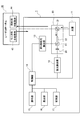
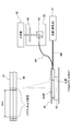
- FIG. 1 is a block diagram showing a schematic configuration of a photodynamic treatment apparatus including a laser catheter and a treatment apparatus according to an embodiment of the present invention.
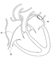
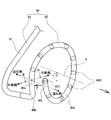
- FIG. It is explanatory drawing which shows the concept of PBI (Photosensitizerbleaching index; drug bleaching index). It is a graph which shows a time-dependent change of the fluorescence detector output in extracellular photodynamic treatment with which the laser catheter which concerns on one Embodiment of this invention is applied. It is a schematic explanatory drawing which shows the state which applied the laser catheter which concerns on one Embodiment of this invention to arrhythmia treatment. It is an explanatory view showing the head part of the laser catheter concerning one embodiment of the present invention.
- FIG. 6 is a cross-sectional view taken along the line BB in FIG. 5; It is cross-sectional explanatory drawing of the modification of the head part of a laser catheter. It is longitudinal cross-section explanatory drawing of the head part of the laser catheter which concerns on one Embodiment of this invention. It is a schematic explanatory drawing of the light diffusing body for irradiation which concerns on one Embodiment of this invention. It is cross-sectional explanatory drawing which shows the head part of the laser catheter which concerns on other embodiment of this invention. It is explanatory drawing which shows the apparatus structure of the fluorescence measurement system of verification experiment 1 (experimental example 1, comparative example 1). It is a graph which shows the spectrum of experiment example 1, comparison example 1, and control 1 of verification experiment 1.
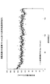
- FIG. 710 nm of verification experiment 2 It is a graph which shows the detected value of wavelength 650-900 nm of return fluorescence in the time of 3 minutes after the light irradiation start in verification experiment 2.
- FIG. 7 It is a graph which shows a fluorescence intensity temporal change in wavelength 710 nm of verification experiment 2.
- the laser catheter 30 will be described as a medical device, but the invention is not limited to this, and sheaths, endoscopes, venous conduits, arterial conduits, tracheoscopies, cystoscopes, calpascopes (culpascope), colonoscopes, trocars, laparoscopes, and other medical tubes, etc., as long as they are medical devices introduced to the tissue to be treated in vivo.
- an example of using the medical device of the present invention for arrhythmia treatment for creating an abnormal electrical conduction blocking line by photodynamic treatment will be described, but is not limited thereto.
- an endoscope for cancer in the pancreas and biliary tract using an ultra-thin endoscope such as a biliary tract endoscope (outside diameter 1 to 3 mm) and a pancreatic endoscope (outside diameter 1 to 2.5 mm)
- the medical device of the present invention can be used if it is a pathological condition that can use a medical device provided with a light emitting probe represented by a laser catheter 30.
- photodynamic therapy such as cancer, infection, arteriosclerosis, etc.
- it can be used for treatment of thrombosis using a laser catheter.
- it can be used in all cases where laser irradiation and laser measurement are performed.
- the proximal side of the laser catheter 30 or the like means the outer side of the living body, that is, the practitioner side in a state where the laser catheter 30 is inserted into the living body, and the distal side of the laser catheter 30 The tip side of the part inserted into the body, that is, the tissue side to be treated.
- the laser catheter 30 of the present embodiment is used together with the treatment apparatus 1 as shown in FIG.
- the combination of the laser catheter 30 and the treatment device 1 corresponds to the light treatment device of the claims.
- the therapeutic device 1 is extracellular photodynamically performed by distributing a sufficient amount of a photosensitizer (hereinafter referred to as PDT drug) in the extracellular stroma and blood vessels in the tissue to be treated as a treatment target site in claims. It is a device for performing treatment (Extra-cellular PDT).
- the treatment apparatus 1 emits light for photodynamic treatment to the light diffuser for irradiation of the laser catheter 30 to perform photodynamic treatment, and at the same time receives return fluorescence from the monitor light diffuser,
- the index value of the information on the treatment progress level is calculated in real time during the treatment and displayed on the screen.
- the practitioner can estimate the degree of injury of the tissue to be treated by light irradiation from time to time while looking at the index value of the information on the treatment progress level displayed on the screen in real time during treatment .
- the extracellular photodynamic therapy of the present embodiment is carried out in a situation where the PDT drug is distributed to the extracellular, ie extracellular fluid and / or cell passage fluid of a living body and continuously supplied due to vascular permeability.
- the treatment apparatus 1 is used for treatment of arrhythmia, but it is good as long as it is an extracellular photodynamic treatment performed by distributing a sufficient amount of PDT drug in extracellular stroma and blood vessels in the tissue to be treated. It can also be used for other treatments, such as photodynamic treatment for infections. Even in cancer treatment (including digestive tract department, respiratory department, brain surgery and dermatology) in which PDT drug accumulates in cells of the treatment target tissue, treatment of arteriosclerosis, etc. It can be used as long as PDT drug and oxygen are continuously supplied in sufficient quantities in quality and blood vessels. It may also be used in angioplasty.
- An arrhythmia to be treated using the treatment apparatus 1 of the present embodiment is an arrhythmia caused by the presence of an abnormal electrical conduction site or an abnormal excitation occurrence site, in particular, a tachyarrhythmia, and conventionally, radiofrequency ablation has been performed. Includes all tachyarrhythmias that have been treated.
- Atrial fibrillation including paroxysmal atrial fibrillation (paroxysmal AF), persistent atrial fibrillation (persistent AF), permanent atrial fibrillation (permanent AF), atrial flutter (AFL: atrial flutter), atrioventricular recurrent tachycardia (AVRT), atrioventricular nodal reentrant tachycardia (AVNRT: atrioventricular nodal reentrant tachycardia), atrial tachycardia (AT: atrial) It can be used for paroxysmal supraventricular tachycardia including tachycardia.
- infections include MRSA infection, gingivitis, periodontitis, peri-implantitis, herpes, canker sores, candiditis and the like.
- the PDT agent used in the present embodiment is a photosensitizer.
- the drug light does not need to be accumulated in the tissue, so the Drug Light interval between drug administration and light irradiation is several minutes to several tens of minutes. As a short time, treatment starts shortly after drug administration. Therefore, it is preferable to use a water-soluble photosensitizer which is rapidly distributed in the interstitium after administration such as intravenous injection and has a rapid excretion.
- ATX-S10 (Iminochlorin aspartic acid derivative, which is a chlorin-based drug having a chlorin skeleton; 80671)
- NPe 6 (664 nm)
- talaporfin sodium There.
- the photosensitization reaction is treated at an early stage after PDT drug administration, that is, at a timing at which the PDT drug is distributed more extracellularly (interstitial space) than intracellularly.
- the target site When the target site is irradiated with laser light transcathetically as a Drug Light interval from administration to light irradiation of a few minutes to a few tens of minutes, the PDT drug and oxygen are sufficiently supplied by the bloodstream At the same time, the light is sufficiently supplied by the laser light, and the photosensitizing reaction by the PDT drug, light and oxygen occurs.
- photosensitizing reactions PDT agents are excited by light irradiation. The energy of this excited PDT drug is transferred to the oxygen present outside the cell to form active singlet oxygen (active oxygen).
- active oxygen active oxygen
- the total production amount of singlet oxygen is an irradiation time integral value of the amount of singlet oxygen per unit time.
- PBI Photosensitizer bleaching index; Drug bleaching index
- PBI Photosensitizer bleaching index; drug bleaching index
- PBI of the following equation 1 is used as an index corresponding to the total bleaching amount.
- FIG. 2 is a graph in which a plurality of rectangles representing the concept of PBI are superimposed on a graph showing a time-dependent change of return fluorescence intensity in an extracellular light-sensitive reaction.
- PBI from fluorescence intensity at the light irradiation time t d that indicates a measurement time, a difference obtained by subtracting the fluorescence intensity in a light irradiation start time t 0, which is the product of irradiation time multiplied by t d up to the measurement time.
- the sides in the horizontal axis direction of the plurality of rectangles in FIG. 2 correspond to the light irradiation time t d until the measurement time. Also, at the start of light irradiation t 0 , that is, at time 0 in FIG. 2, since light irradiation has not started yet, drug bleaching has not yet occurred, and the return fluorescence intensity fluo (t) has the highest value. is there. Then, since light irradiation is performed after time 0, drug bleaching proceeds with the elapse of measurement time t d , and fluo (t) decreases.
- the direction of the longitudinal axis of the sides of each rectangle is the fluorescence intensity at the light irradiation time t d that indicates a measurement time, which corresponds to a difference obtained by subtracting the fluorescence intensity in a light irradiation start time t 0.
- PBI corresponds to the area of each rectangle in FIG.
- Equation 1 it is assumed that oxygen and PDT drug are supplied at a constant rate and in sufficient amounts due to the permeability from blood vessels to the stroma. Therefore, the amount of light energy input is the rate-limiting step. Also, the measured values of fluorescence include measured values of fluorescence of PDT drug from both blood and stroma, and it is assumed that the abundance ratio is constant.
- the PBI obtained by the equation 1 can be made an index with a high utility value according to the actual situation by calculating the corrected corrected PBI.
- the correction method is divided into a correction method using the fluorescence intensity temporal change waveform itself and a correction method using tissue physiological information and the like acquired by other methods.
- the following 1, 2, 3 will be described based on the graph of FIG.
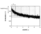
- FIG. 3 is a graph showing the time-dependent change of the fluorescence detector output in extracellular photodynamic therapy. As shown in FIG. 3, in extracellular photodynamic therapy, it is confirmed that the fluorescence intensity detected by the fluorescence detection unit 12 in FIG.
- a period from the start of light irradiation to the end of light irradiation is a first light emission period from the start of light irradiation to the steady state, and a steady state to the end of light irradiation following the first light emission period. It can be divided into two light emitting periods.
- a corrected PBI can be obtained by multiplying the PBI obtained in Equation 1 by the output of the fluorescence intensity at the start of light irradiation. Since the fluorescence intensity at the start of light irradiation reflects the PDT drug concentration, such a correction makes it possible to obtain a corrected PBI in which the PDT drug concentration distributed in the tissue is taken into consideration.
- the ratio of the fluorescence intensity at the start of light irradiation to the fluorescence intensity in the steady state indicates that it is a transient state before the steady state in the first light emission period. Since PBI shows the progress of the reaction in the steady state, the transient of the first light emission period is performed using the first emission period and the ratio of the fluorescence intensity at the start of light irradiation and the fluorescence intensity in the steady state as two indicators. The PBI is corrected according to the current state so as to reflect the photosensitization reaction of the state. In the first emission period, the balance between the supply of PDT agent and oxygen by vascular permeability or blood flow and the consumption of PDT agent and oxygen by photodynamic therapy differs from the second emission period in steady state.
- the correction method 2 is a transient state caused by the balance between the supply of PDT drug and oxygen by blood vessel permeability or blood flow and the consumption of PDT drug and oxygen by photodynamic therapy being different from the steady state.
- the corrected PBI can be made consistent with the actual state of the light emission period.
- the corrected PBI can be obtained by dividing the PBI obtained by the equation 1 by the intensity of the return excitation light at the irradiation time. By making such corrections, it is possible to obtain a correction PBI in which differences in optical characteristics in each tissue to be treated are taken into consideration.
- physiological information obtained by other methods
- the physiological information of the tissue obtained by measurement by the other method information on the general condition of the patient obtained from a general living body monitoring device, or the target tissue Correct using known physiological values.
- physiological information, information on general condition, and physiological values are, for example, PaO 2 (arterial blood oxygen partial pressure), SpO 2 (percutaneous arterial blood oxygen saturation), oxygen concentration, total hemoglobin amount, oxygenated hemoglobin Amount, amount of hemoglobin such as amount of deoxygenated hemoglobin, blood flow velocity in each tissue, blood flow volume, blood vessel running density per unit volume, blood content, patient temperature, target tissue temperature, albumin, HDL Protein concentration, serum protein concentration such as LDL (low density lipoprotein).
- PaO 2 arterial blood oxygen partial pressure
- SpO 2 percutaneous arterial blood oxygen saturation
- oxygen concentration total hemoglobin amount
- oxygenated hemoglobin Amount amount of hemoglobin such as amount of deoxygenated hemoglobin
- blood flow velocity in each tissue blood flow volume
- blood vessel running density per unit volume blood content
- the oxygen concentration is a factor that affects the reaction efficiency and the oxygen supply.
- the amount of hemoglobin is a factor that affects the oxygen supply.
- Blood flow rate and blood flow rate are factors affecting PDT drug and oxygen supply.
- Temperature is a factor that affects the reaction efficiency.
- the amount of serum protein affects the supply of PDT drug because serum protein binds to the PDT drug.
- FIG. 1 is a block diagram showing a schematic configuration of a treatment apparatus 1 of the present embodiment.
- the treatment apparatus 1 includes a light source 11, an optical system 20, a fluorescence detection unit 12, a return excitation light detection unit 13, a control unit 14, an operation unit 15, a display unit 16, and a storage unit 17. ing.
- the light source 11 outputs excitation light that excites the PDT drug.
- the wavelength of light output from the light source 11 is equal to the absorption wavelength of the Q band of PDT drug.
- talaporfin sodium is used as a PDT agent
- the wavelength of the light output from the light source 11 is not limited to this.
- a laser device such as a semiconductor laser device, a light emitting diode or a lamp light source is used.
- the excitation light output from the light source 11 is incident on the irradiation light diffuser 44 of the laser catheter 30 by the optical system 20.
- the input power of the light source 11 be 1000 mW or less, preferably 500 mW or less
- the output of the light diffuser 44 for irradiation of the laser catheter 30 be 150 mW / cm or less, preferably 75 mW / cm or less. It is.
- the intensity of light irradiation from the light diffuser for irradiation 44 can be set to an appropriate intensity, and it can be prevented that the deep penetration region becomes too wide.
- the optical system 20 causes the excitation light emitted from the light source 11 to enter the irradiation light diffuser 44 of the laser catheter 30 via the polarization beam splitter 21. Further, the fluorescence emitted from the PDT drug irradiated with the excitation light and the excitation light returned from the laser catheter 30 are extracted from the monitor light diffuser 45 as a light diffuser for receiving light of the laser catheter 30, respectively, It enters the return excitation light detection unit 13. In the present embodiment, the monitor light diffuser 45 performs only light reception, but the present invention is not limited to this, and the monitor light diffuser 45 may emit excitation light for measurement.
- the optical system 20 includes a polarization beam splitter 21, an optical fiber 22, a dichroic mirror 23, and a band pass filter 24.
- the excitation light from the light source 11 is incident on the irradiation light diffuser 44 of the laser catheter 30. Part of the excitation light from the light source 11 is reflected by the optical fiber 44 f connecting the treatment apparatus 1 and the laser catheter 30 and the side end face of the connector (not shown) or the tip of the laser catheter 30 to be return excitation light
- the light is incident on the polarization beam splitter 21. Further, the fluorescence from the monitor light diffuser 45 of the laser catheter 30 also enters the polarization beam splitter 21.
- the polarization beam splitter 21 reflects the light incident from the monitoring light diffuser 45 of the laser catheter 30 and guides the light to the dichroic mirror 23 through the optical fiber 22.
- the dichroic mirror reflects light of wavelength 680 to 690 nm or less and transmits light of wavelength 680 to 690 nm or more.
- the fluorescence having a peak wavelength of about 710 nm is transmitted and guided to the fluorescence detection unit 12 through the band pass filter 24, and the return excitation light having a peak wavelength of about 663 nm is reflected and guided to the return excitation light detection unit 13.
- the band pass filter 24 is a filter that transmits a wavelength of 710 ⁇ 2 nm.
- the dichroic mirror 23 and the band pass filter 24 transmit and reflect light of the wavelength as described above.
- talapolfin is used as the PDT agent.
- agents other than sodium it is not limited to this.
- the fluorescence detection unit 12 and the return excitation light detection unit 13 are formed of known linear image sensors, and detect fluorescence of the PDT drug incident from the optical system 20 and return excitation light from the laser catheter 30, respectively.
- the fluorescence detection unit 12 and the return excitation light detection unit 13 supply the detected fluorescence and return excitation light to the control unit 14 as an electrical signal.
- the monitor of the operation status confirmation of the treatment apparatus 1 is whether the excitation light for treatment is appropriately irradiated under the conditions such as the light amount as set. It can also be used as
- the fluorescence detection unit 12 includes detection elements such as a silicon photodiode, an avalanche photodiode, a spectroscope, and a photomultiplier.
- the sampling rate of the measurement by the detection element is 10 to 1000 Hz, preferably 100 to 500 Hz.
- the control unit 14 controls each unit in the treatment apparatus 1.
- the control unit 14 calculates the fluorescence intensity and the return excitation light intensity based on the electric signals acquired from the fluorescence detection unit 12 and the return excitation light detection unit 13, and based on these intensities, information on the degree of injury is calculated. Calculate in real time.
- the control unit 14 also outputs a display instruction for displaying the calculation result to the display unit 16.
- the storage unit 17 is a non-volatile memory, and is set to, for example, a flash memory, an HDD, or another solid-state memory.
- the control unit 14 acquires the calculated fluorescence intensity, excitation light intensity, information on the degree of injury, time obtained from a reference time such as the start time of excitation light, etc. The information is associated with each other and recorded in the storage unit 17 as change over time.
- the display unit 16 is a display device using, for example, a liquid crystal display.
- the display unit 16 displays, for example, information on the degree of injury and time information on the display screen in real time, based on the display information included in the display instruction.
- the operation unit 15 receives an instruction based on an input operation from a practitioner, and outputs the received instruction to the control unit 14.
- the command is, for example, a command related to on / off of excitation light output from the light source 11 and switching of the intensity.
- a laser catheter 30 shown in FIGS. 4 to 9 is detachably connected to the treatment apparatus 1 at the end of a tube (not shown) connected to the treatment apparatus 1 by a connector (not shown).
- the laser catheter 30 is, as shown in FIGS. 4 and 5, a head unit 40 provided at the distal end of the laser catheter 30 and an elongated unit connected to the head unit 40 and provided near the head unit 40.
- a control handle (not shown) is connected to a proximal portion on the opposite side of the head portion 40 of the tubular portion 50.
- a connector (not shown) is provided on the proximal portion on the opposite side of the tubular portion 50 of the control handle.
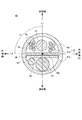
- the head unit 40 includes a light diffuser for irradiation 44 and a light diffuser for monitoring in a transparent tube 41 as a medical device main body molded from a hollow flexible transparent material.
- a loop 45 is formed by inserting a reflecting plate 46, a shape memory wire 47, and a lead wire 48, and the shape memory wire 47 has a spiral shape of more than one turn.
- the shape of the head portion 40 of the laser catheter 30 is also referred to as a lasso, and although it is not strictly closed annular but pseudo-annular, it is also referred to as ring or annular.
- the transparent tube 41 is a soft hollow cylindrical transparent tube made of polyether block amide copolymer (Pebax (registered trademark), manufactured by Arkema Co., Ltd.) or the like.
- the transparent tube 41 may also be made of polyethylene phthalate (PET), polytetrafluoroethylene (PTFE), polymeric electrically non-conductive material, such as polyethylene terephthalate (PET), polytetrafluoroethylene (PTFE), fluorinated ethylene propylene (FEP).
- An optically clear polymeric electrically non-conductive material such as perfluoroalkoxy (PFA), urethane, polyurethane or polyvinyl chloride (PVC) may be used. As shown in FIGS.
- the transparent tube 41 includes an inner peripheral side lumen 42 and an outer peripheral side lumen 43 which are separated by a partition wall 41 w.
- the entire transparent tube 41 is formed of a transparent tube, but the present invention is not limited to this, and at least the outer peripheral wall portion 41 o of the outer peripheral side lumen 43 should be transparent Just do it. Therefore, the wall portion 41i on the inner circumferential side and the partition wall 41w may be made of a translucent or opaque material.
- the inner circumferential side lumen 42 is a lumen having a substantially semicircular cross section positioned on the inner circumferential side which is the center C side of the spiral shape, and is divided by the wall portion 41i of the transparent tube 41 on the inner circumferential side and the partition wall 41w.
- a shape memory wire 47 is inserted inside the inner side lumen 42 so as to face the wall portion 41i and the partition wall 41w at the center in the longitudinal direction of the cross section, and shape memory wire at both ends in the longitudinal direction of the cross section Ten lead wires 48 are inserted so as to sandwich 47 therebetween.
- the shape memory wire 47 is a wire formed of a nickel titanium alloy having a substantially circular cross section and having shape memory characteristics.
- an iron-based shape memory alloy such as an iron-manganese-silicon alloy, a bimetal in which two metal plates having different thermal expansion coefficients are bonded, or the like may be used.
- one end of a curved spiral shape of about 1.1 turns is bent at an angle greater than or equal to a right angle so as to maintain the shape of the head portion 40 of FIGS. It is formed to maintain the same shape.
- the shape memory wire 47 is not shown in FIG.
- the distal end of the shape memory wire 47 is fixed to the tip electrode 49T and is proximally The end is fixed to the tubular portion 50.
- the shape memory wire 47 has elasticity and can be deformed according to the pressure in the state of receiving an external pressure. Therefore, when the head 40 is in the blood vessel, the pressure from the side wall of the blood vessel draws a shape such as a gentle curve along the shape of the blood vessel.
- the lead wire 48 is a lead wire used in a general electrode catheter, and each of the ten lead wires 48 is nine ring electrodes 49R and one tip electrode formed on the outer periphery of the head portion 40.
- the 49T is crimped and connected by a known method.
- the outer peripheral side lumen 43 is a lumen having a substantially semicircular cross section located on the outer peripheral side opposite to the center C of the spiral shape, and is divided by the wall portion 41 o of the transparent tube 41 outer peripheral side and the partition wall 41 w .
- a reflective plate 46 is disposed inside the outer peripheral side lumen 43 so as to abut on the partition wall 41w.
- the light diffuser for irradiation 44 is inserted at the center in the longitudinal direction of the cross section so as to face the wall 41 o and the reflecting plate 46, and adjacent to the light diffuser for irradiation 44, the monitor light diffuser 45 Is inserted. As shown in FIG.
- the cladding 54c and the coating 54d are removed from the optical fiber cable 54 inserted in the tubular portion 50, and the core is exposed over a predetermined length from the tip 44t. It is comprised from the light-diffusion body main body 44a which becomes, and the resin layer 44b which coat
- the light diffuser body 44a is integrally formed with the core 54a of the optical fiber cable 54 inserted into the tubular portion 50, is formed by sandblasting, and has an angle with respect to the length direction of the light diffuser body 44a.
- the outgoing light to the side is made uniform.
- the present invention is not limited to this, and the light diffuser body 44a is provided with a hollow portion in the center and a light reflection mirror provided on the inner surface, or a notch is provided on the inner surface, or the like.
- the emitted light may be made uniform.
- the resin layer 44 b is formed, for example, by applying it to an acrylic ultraviolet curable resin in which fine quartz powder is dispersed, and curing it with ultraviolet light.
- a connector (not shown) is fixed to the end of the optical fiber cable 54 on the opposite side of the light diffusing body 44 for irradiation, and this connector is connected to a laser generator (not shown) containing a laser source (not shown). It is configured to be possible.
- the light diffuser for irradiation 44 is not limited to the one shown in FIG. 9 but may be another one.
- As a method of forming the light diffusion body 44 for irradiation it divides roughly and the case where the core 54a of the optical fiber cable 54 is extended and the light diffusion body 44 for irradiation is comprised, and the light for irradiation separately from the core 54a
- the case where the diffusion body 44 is provided is roughly divided into two, and any of them can be used as the light diffusion body 44 for irradiation of the present embodiment.
- the core 54a may or may not constitute the diffusion substance itself.
- transmission light leakage methods (a method in which the cladding 54c is finely scratched to expose a part of the core 54a, a method in which a leak is configured by bending, and the like) and a method using a diffusion material are roughly classified.
- Transmission light leakage methods include scratch processing (sandblast, stamping, solvent treatment, etc.), fiber Bragg grating (FBG), micro bending, and the like.
- a method of using a diffusion material there is a method of putting a diffusion material in the core 54a / clad 54c, a method of exposing the core 54a and putting a diffusion material in the coating 54d.
- sandblasting is a method of spraying a fine particle, it applies also to the system which uses this spreading
- the case where an optical element different from the core 54a is used as the light diffusion body 44 for irradiation is applied.
- an optical element such as a polyhedral prism or a SELFOC (registered trademark) lens (refractive index distribution type lens) is used as the light diffuser for irradiation 44.
- the irradiation light diffuser 44 extends over the entire length of the head 40, and although depending on the shape of the tissue to be treated, the diameter of the spiral shape in FIG. Since an appropriate length is 50 to 50 mm, preferably 5 to 15 mm, the total length of the light diffuser for irradiation 44 is about 1.5 to 15 cm, preferably about 3 to 9 cm.
- the diameter of the light diffuser for irradiation 44 is 0.1 to 1.0 mm, preferably 0.25 to 0.75 mm.
- the light diffuser for irradiation 44 is used to irradiate the light from the light source to the site to be treated.
- the diameter of the monitor light diffuser 45 is 0.1 to 1.0 mm, preferably 0.25 to 0.75 mm.
- the monitor light diffuser 45 has the same configuration as the irradiation light diffuser 44.
- the monitor light diffuser 45 receives return fluorescence and is used to measure information on the degree of injury. Since the light diffuser for irradiation 44 and the light diffuser for monitoring 45 are adjacent to each other, there is a risk that signal deterioration may occur due to interference (crosstalk) of the signals leaked from each other when they contact or rub each other. . Therefore, the light diffuser for irradiation 44 and the light diffuser for monitoring 45 may be adhered to each other with a transparent adhesive, or a transparent spacer may be provided between each other.
- the light diffuser for irradiation 44 and the light diffuser for monitoring 45 are separately configured, but may be integrally configured.
- the light diffuser for irradiation 44 and the light diffuser for monitoring 45 may be formed of a single light diffuser. At this time, using a single light diffuser, irradiation and light reception may be performed by switching between the irradiation time zone and the light reception time zone on the time axis.
- the reflecting plate 46 is used to suppress the light emitted by the monitoring light diffuser 45 from being emitted toward the inner peripheral side of the spiral shape and to be emitted toward the outer peripheral side.
- the reflecting plate 46 is used to suppress the radiation toward the inner peripheral side of the spiral shape, it is possible to intensively irradiate light to the tissue to be treated and prevent the irradiation of light to the tissue other than the tissue to be treated.
- the reflecting plate 46 has a thickness of 0.01 to 0.10 mm, preferably 0.03 to 0.08 mm, made of aluminum, and has a length similar to that of the light diffuser for irradiation 44 and the light diffuser for monitoring 45 It consists of a rectangular plate of a scale.
- the reflector 46 may be made of other materials such as gold and silver, which have high reflectance to excitation light.
- a plate bent in a U-shaped cross section or in a V shape may be used so that the center in the width direction is located on the center C side of the spiral shape.
- Aluminum, gold, silver or the like may be plated on the surface of the spiral shape inner peripheral side of the light diffuser for monitoring 44 and the light diffuser for monitoring 45.
- the ring electrode 49R and the tip electrode 49T are made of a conductive material such as platinum, gold, iridium, or an alloy thereof.
- the ring-shaped electrode 49R is configured such that the width in the extension direction of the head portion 40 is 1 mm or less, preferably 0.6 mm or less, so as not to block light emission.
- the ring-shaped electrode 49R is formed of gold, light absorption by the ring-shaped electrode 49R is suppressed, which is preferable.
- a side hole 40h is formed at the position where the ring electrode 49R of the head unit 40 is attached, and the nine lead wires 48 and the ring electrode 49R are formed through the side hole 40h. And are connected. Further, a tip hole is also formed at the distal tip of the head portion 40, and one lead wire 48 and the tip electrode 49T are connected through the tip hole.
- the lead wire 48 is configured by covering a metal core wire having a diameter of about 0.075 mm with a resin such as a polyamideimide resin having a film thickness of about 10 ⁇ m. Also, in the present embodiment, nine ring electrodes 49R and one tip electrode 49T are provided, but the number of ring electrodes 49R is not limited to this and may be about seven to nine.
- the number of ring electrodes 49R may be about four.
- the lead wire 48 is connected to a potential detection device (not shown) via a connector (not shown).
- signals of potentials derived from the ring electrode 49R and the tip electrode 49T are input to the potential detection device (not shown), and information on the contact state of each ring electrode 49R and the tip electrode 49T with the tissue to be treated, Information on the depth of treatment is calculated and displayed by known methods.
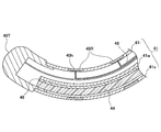
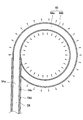
- the head unit 40 includes the shape memory wire 47, as shown in FIG. 5, the distal end of the distal end has a spiral shape of about 1.1 turns in a state where it receives no external force. And has a shape bent at an angle of about 90.degree. To 105.degree. At a bending portion 40b at the proximal end of the loop portion 40c.
- a force F is applied to the distal end 40t of the distal end of the loop 40c in the head 40 along the direction of the central axis A of the loop 40c toward the bending portion 40b, the distal end 40t And the bent portion 40b contact each other, and the head portion 40 forms a closed annular shape. Therefore, as shown in FIG.
- the head portion 40 forms a closed annular shape by simply pressing the head portion 40 lightly against an annular treatment target such as a vein, and the light diffusion for irradiation stored in the inside.
- the body 44 also forms a closed annular shape, allowing the formation of a gapless anomalous electrical conduction blocking line.
- the head part 40 may be comprised in the cyclic
- the dividing wall 41w and the reflecting plate 46 are formed along a straight line L1 parallel to the central axis A of the loop portion 40c of FIG. That is, the straight line L1 is perpendicular to the straight line r connecting the center 40o of the cross section of the head portion 40 and the center C of the loop portion 40c.
- the partition wall 41w and the reflection plate 46 may be provided along L2 inclined by an angle ⁇ ° such that 0 ° ⁇ ⁇ 90 ° with respect to L1.
- the partition wall 41w and the reflector plate 46 have the transparent tube 41 in a plane having an angle of more than 0 ° and less than 90 ° with respect to the central axis A, that is, the inner circumference and the outer circumference and the outer circumference Separated to the side.
- the tissue target end (distal end) of the partition 41w is on the inner peripheral side of the spiral shape. It is inclined with respect to the straight line L1 so as to be located.
- the tissue to be treated is not completely outside the loop-like portion 40c but slightly distal to the outer circumference
- the tubular portion 50 includes a fiber optic cable 54 continuous with the light diffusing body 44 for irradiation and a fiber optic cable (not shown) continuous with the light diffusing body 45 for monitoring in a tube 51 constituting an outer shell of the tubular portion 50.
- Ten lead wires 48 are inserted.
- the tube 51 is made of polyether block amide copolymer (Pebax (registered trademark), manufactured by Arkema Co., Ltd.), polyethylene phthalate (PET), polytetrafluoroethylene (PTFE), polymeric electrically nonconductive material such as polyethylene terephthalate PET), polytetrafluoroethylene (PTFE), fluorinated ethylene propylene (FEP), perfluoroalkoxy (PFA), urethane, polyurethane, or resin such as polyvinyl chloride (PVC).
- the tube 51 may or may not be transparent.
- the tube 51 has certain flexibility (flexibility), incompressibility in the axial direction, and torsional rigidity. Due to the torsional rigidity of the tube 51, the rotational torque from the control handle (not shown) can be transmitted to the head portion 40.
- the optical fiber cable 54, an optical fiber cable (not shown) continuous to the light diffuser for monitoring 45, ten leads 48 are connectors not shown via a control handle (not shown) connected to the proximal portion of the tubular portion 50 It is extended to the end of the tube (not shown) connected to the treatment apparatus 1 by a connector (not shown).
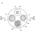
- a head unit 40 'shown in FIG. 10 may be used.
- the head portion 40 ' has a total of four lumens extending along the length direction of the head portion 40', as shown in FIG. That is, the wire lumen 42a 'through which the shape memory wire 47 is inserted, the lead wire lumen 42b' through which the lead wire 48 is inserted, the irradiation light diffuser lumen 43a 'through which the irradiation light diffuser 44 is inserted, monitoring light A monitor light diffuser lumen 43b 'through which the diffuser 45 is inserted is provided.
- a single integrated light diffuser is provided instead of the irradiation light diffuser 44 and the monitor light diffuser 45, a total of three lumens for the light diffuser are sufficient. It may be configured to have a lumen.
- the reflection coils 46a 'and 46b' are wound.
- the reflective coils 46a 'and 46b' function as reflectors.
- the reflector may be configured by plating and coating aluminum, gold, silver or the like on the inner peripheral surface of the wire lumen 42a' and the lead wire lumen 42b '.
- the reflector may be configured by plating aluminum, gold, silver or the like on the surface of the spiral shape inner peripheral side of the light diffuser for irradiation 44 and the light diffuser for monitor 45.
- the other configuration of the head unit 40 ' is the same as that of the head unit 40, and thus the description thereof is omitted.
- a laser catheter 30 is inserted into the heart through a patient's femoral vein or jugular vein (not shown) by a practitioner such as a doctor.
- the tip of the laser catheter 30 is disposed in the vicinity of the pulmonary vein of the inner wall of the myocardial tissue in the left atrium.
- the practitioner administers to the patient a dose of PDT drug necessary for treatment by intravenous injection.
- the administered PDT drug diffuses into the stroma or blood vessels.
- the light source 11 When the light source 11 is turned on (not shown) by a practitioner after a predetermined time, for example, several minutes to several tens of minutes after PDT drug administration, emission of excitation light from the light source 11 is started, and the excitation light is The light is emitted from the entire length of the light diffusing body 44 for irradiation of the laser catheter 30.
- a timer (not shown) is turned on.
- the control unit 14 calculates the intensity of the fluorescence detected by the fluorescence detection unit 12 when the switch of the light source 11 is turned on, and stores the intensity in a memory (not shown). Next, the control unit 14 determines whether a preset measurement time interval ⁇ t (for example, 0.05 second to 0.5 second) has elapsed from the previous calculation time of the fluorescence intensity, If it has elapsed, the intensity of fluorescence at that time detected by the fluorescence detection unit 12 is calculated and stored in a memory (not shown).
- a preset measurement time interval ⁇ t for example, 0.05 second to 0.5 second
- the control unit 14 acquires a light irradiation time indicating the time from the start of light irradiation to that time from a timer (not shown), and the return excitation light of that time detected by the return excitation light detection unit 13 at that time.
- the intensity is calculated, and the estimated treatment depth d nec is calculated according to the above-mentioned equation 1 (2) using the calculated fluorescence intensity at that time.
- the control unit 14 transmits data of the calculated estimated treatment depth d nec to the display unit 16 and stores the data in a memory (not shown).
- the estimated treatment depth d nec is displayed on the display unit 16 in real time so as to be visible to the practitioner.
- the estimated treatment depth d nec is displayed not as the absolute depth of the injury given to the tissue by photodynamic treatment but as an index value consisting of relative values. For example, it may be an integer or a digit "3", "5.3” or the like having one or two decimal places.
- the estimated treatment depth d nec using the correction PBI corrected by the correction method using such acquired tissue physiological information by other methods, display and calculate the correction putative therapeutic depth d nec, it is stored Good.
- PBI or corrected PBI is used as an index value of information related to the degree of injury of photodynamic treatment, but the present invention is not limited to this.
- the fluorescence intensity detected at 12 may be used.
- the fluorescence intensity is displayed as it is or appropriately processed, displayed on the display unit 16, and stored in a memory (not shown).
- the control unit 14 determines whether a preset measurement time has elapsed and whether the light source 11 has been switched off, and the measurement time has not yet elapsed and the light source 11 is switched off. If not, the calculation and display of the estimated treatment depth d nec are repeated.
- control unit 14 stores the data stored in the memory (not shown) as the photodynamic treatment has ended. Save in section 17 and end the process.
- Optical fibers 44f and 45f consisting of two 500 ⁇ m, NA 0.5, diffusion length 5 cm diffusion type plastic optical fibers (Cylindrical probe, manufactured by Medlight) are arranged in parallel on the myocardial tissue 65 of Experimental example 1 and parafilm is used. They were bundled together and fixed so that the entire length of the diffuser portion at the tip was in contact with the myocardial tissue 65.
- the diffusion part of the optical fiber 44 f is a light diffusion body for irradiation 44
- the diffusion part of the other optical fiber 45 f is a light diffusion body for monitoring 45.
- a glass plate 66 was placed on the myocardial tissue, the light diffuser for irradiation 44, and the light diffuser for monitoring 45.
- the tip of the optical fiber 44 f was connected to the light source 61 of red laser (Rouge-LD-02B, manufactured by Cyber Laser Co., 663 ⁇ 2 nm), and the tip of the optical fiber 45 f was connected to the dichroic mirror 63 of the optical system 60 .
- the optical system 60 includes a dichroic mirror 63 (XF 2024, manufactured by OMEGA), a long pass filter 64 (LVX 0690, manufactured by Asahi Spectroscopic Co., Ltd.), and is connected to the spectroscope 62 (PMA 12, manufactured by Hamamatsu Photonics Co., Ltd.) .
- XF 2024 manufactured by OMEGA
- LVX 0690 long pass filter 64
- PMA 12 manufactured by Hamamatsu Photonics Co., Ltd.
- a laser beam with a wavelength of 663 ⁇ 2 nm was irradiated for 200 seconds with an input power of 0.3 W from the optical fiber 44 f via the irradiation light diffuser 44.
- the return light received from the optical fiber 45f through the monitor light diffuser 45 with time was spectrally measured by the spectroscope 62 at a wavelength of 300 to 1050 nm and an integration time of 500 ms.
- the same measurement was performed also about the porcine myocardial tissue of the comparative example 1 which is not immersed in a chemical
- FIG. 12 The spectra of Experimental Example 1, Comparative Example 1, and Control 1 are shown in FIG. From FIG. 12, the return fluorescence from the monitoring light diffuser 45 is detected only in Experimental Example 1 in which the cardiac muscle tissue is immersed in the drug, and the irradiation light diffuser 44 and the monitoring light are detected in the presence of the PDT drug. It was demonstrated that when the diffuser 45 is disposed adjacent to the tissue to be treated as shown in FIG. 12, it is possible to measure the return fluorescence intensity in the tissue to be treated.
- the time-dependent change of the fluorescence intensity measured by wavelength 704 nm about Experimental example 1 is shown in FIG.
- the fluorescence intensity is maximum at the wavelength 704 nm
- the temporal change of the fluorescence intensity at the wavelength 704 nm is verified.
- the return fluorescence intensity of the myocardial tissue at a wavelength of 704 nm in Experimental Example 1 drops to a value of about 1 ⁇ 4 of the irradiation start point in 200 seconds, and the myocardial tissue at a wavelength of 704 nm in Experimental Example 1 It was found that the time course of the return fluorescence intensity is similar to the time course of the fluorescence intensity of FIG.
- a solution (30 ⁇ g / ml, serum protein free) containing physiological saline and talaporfin sodium is used instead of arranging the myocardial tissue 65 under the same conditions.
- the fluorescence spectrum when the return fluorescence was measured (Control 2) is shown in FIG.
- the light diffuser for direct irradiation 44 and the light diffuser for monitoring 45 are placed on a solution (30 ⁇ g / ml) consisting of physiological saline and talaporfin sodium to obtain fluorescence intensity It measured.
- the fluorescence spectrum obtained in Control 2 substantially matches the spectrum shape in FIG.
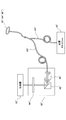
- Verification Experiment 2 the operability of a fluorescence monitor using a loop laser catheter was investigated in an in vivo animal experiment under catheter intervention using the apparatus configuration of the fluorescence measurement system of FIG.
- a laser catheter 30 ' is manufactured by coating two 7 cm long plastic optical fibers (250 ⁇ m in diameter) on the looped tip of a conventional general-purpose catheter in which the distal tip is formed in a loop shape
- Verification experiment of fluorescence monitor by a laser catheter as a medical device of the present invention was conducted by emitting diffusion excitation light by one tube and receiving fluorescence by another tube. The contents of this verification experiment will be described below. This experiment was conducted according to the following procedure.
- a sheath (10 Fr.) was inserted and indwelled into the right femoral vein of a dog (hybrid species, male, 19 kg body weight).
- the looped laser catheter 30 ' was inserted into the sheath and placed in the superior vena cava.
- the loop type laser catheter 30 ' is a plastic having two diffusion lengths of 7 cm along the extension direction of a general loop (lasso type) catheter used for mapping or cauterization for pulmonary veins, etc.
- the optical fibers 44 f ′ and 45 f ′ were made by packaging.
- the tip of the two optical fibers 44f 'and 45f' covers the irradiation light diffuser 44 'having a diffusion length of 7 cm and the monitoring light diffuser 45' over the length of one turn of the loop portion of the catheter. Placed.
- the tip of the optical fiber 44f ' is connected to a light source 61' of red laser (Rouge-LD-02B, manufactured by CYBER LASER CO., LTD., 663 ⁇ 2 nm), and the tip of the optical fiber 45f 'is a polarized beam of the optical system 60'. Connected to splitter 65 '.
- the optical system 60 includes a polarization beam splitter 65 ', a dichroic mirror 63' (XF 2024, manufactured by OMEGA), and a long pass filter 64 '(LVX 0690, manufactured by Asahi Spectroscopic Co., Ltd.), and a spectroscope 62' (PMA12, Hamamatsu Photonics) Connected to the company.
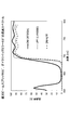
- FIG. 16 shows filter characteristics at a wavelength of 600 to 790 nm when the dichroic mirror 63 'alone, the long pass filter 64' alone, and the dichroic mirror 63 'and the long pass filter 64' are used in combination.
- DM indicates a dichroic mirror 63 ′
- LPF indicates a long pass filter 64 ′.
- the catheter position is adjusted under fluoroscopy so that the irradiation light diffuser 44 ′ and the monitoring light diffuser 45 ′ contact the superior vena cava, and the PDT drug talaporfin sodium (2.5 mg / kg bolus, 2. 93 mg / kg / hr infusion) was intravenously administered.
- the PDT drug talaporfin sodium 2.5 mg / kg bolus, 2. 93 mg / kg / hr infusion
- 62 minutes after drug administration plasma drug concentration: 42 to 48 ⁇ g / ml
- Light was continuously applied to the superior vena cava for 3 minutes.
- the return fluorescence from the monitoring light diffuser 45 ′ was measured over time by the spectroscope 62 ′ at a wavelength of 650 to 900 n
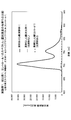
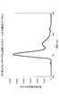
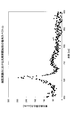
- FIG. 17 is a graph showing the detection values of the return fluorescence wavelength of 650 to 900 nm at the start of light irradiation
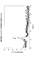
- FIG. 18 shows the detection values of the return fluorescence wavelength of 650 to 900 nm three minutes after the start of light irradiation. It is a graph. From FIG. 17 and FIG. 18, focusing on the drug-derived fluorescence peak intensity near the wavelength of 710 nm, the fluorescence intensity at a time point of 3 minutes after the start of irradiation is lower than that at the irradiation start. It was confirmed that it was attenuated.
- each point is a plot of measurement data, and a solid line indicates a 3-interval moving average.
- the moving average is an average value obtained at regular intervals in a time series while shifting a section, and can represent a long-term change trend on a graph.
Landscapes
- Health & Medical Sciences (AREA)
- Biomedical Technology (AREA)
- Engineering & Computer Science (AREA)
- Life Sciences & Earth Sciences (AREA)
- Animal Behavior & Ethology (AREA)
- Pathology (AREA)
- Nuclear Medicine, Radiotherapy & Molecular Imaging (AREA)
- Radiology & Medical Imaging (AREA)
- General Health & Medical Sciences (AREA)
- Public Health (AREA)
- Veterinary Medicine (AREA)
- Biophysics (AREA)
- Physics & Mathematics (AREA)
- Optics & Photonics (AREA)
- Radiation-Therapy Devices (AREA)
- Laser Surgery Devices (AREA)
- Media Introduction/Drainage Providing Device (AREA)
Priority Applications (2)
| Application Number | Priority Date | Filing Date | Title |
|---|---|---|---|
| EP14860490.3A EP3067092A4 (en) | 2013-11-07 | 2014-11-06 | Medical instrument and light-ray treatment device |
| US15/035,034 US20160287894A1 (en) | 2013-11-07 | 2014-11-06 | Medical instrument and light-ray treatment device |
Applications Claiming Priority (2)
| Application Number | Priority Date | Filing Date | Title |
|---|---|---|---|
| JP2013231496A JP2015089489A (ja) | 2013-11-07 | 2013-11-07 | 医療用具及び光線治療装置 |
| JP2013-231496 | 2013-11-07 |
Publications (1)
| Publication Number | Publication Date |
|---|---|
| WO2015068758A1 true WO2015068758A1 (ja) | 2015-05-14 |
Family
ID=53041534
Family Applications (1)
| Application Number | Title | Priority Date | Filing Date |
|---|---|---|---|
| PCT/JP2014/079420 Ceased WO2015068758A1 (ja) | 2013-11-07 | 2014-11-06 | 医療用具及び光線治療装置 |
Country Status (4)
| Country | Link |
|---|---|
| US (1) | US20160287894A1 (enExample) |
| EP (1) | EP3067092A4 (enExample) |
| JP (1) | JP2015089489A (enExample) |
| WO (1) | WO2015068758A1 (enExample) |
Cited By (1)
| Publication number | Priority date | Publication date | Assignee | Title |
|---|---|---|---|---|
| JP2023056636A (ja) * | 2021-10-08 | 2023-04-20 | 株式会社島津製作所 | 治療支援用光源ユニットおよびその制御方法 |
Families Citing this family (9)
| Publication number | Priority date | Publication date | Assignee | Title |
|---|---|---|---|---|
| EP3498211B1 (en) | 2013-08-09 | 2024-12-25 | The General Hospital Corporation | Apparatus for treating dermal melasma |
| WO2017162869A1 (en) * | 2016-03-25 | 2017-09-28 | INSERM (Institut National de la Santé et de la Recherche Médicale) | System for treatment by photodynamic therapy of a cavity of a patient's body and method for preparation of such system |
| IT201600113597A1 (it) * | 2016-11-10 | 2018-05-10 | Elesta S R L | Dispositivo per termoablazione laser con un diffusore elicoidale e apparecchiatura comprendente detto dispositivo |
| KR101881226B1 (ko) * | 2016-12-02 | 2018-07-24 | 김용철 | 내시경용 카테터 조립체 |
| CN110073260B (zh) * | 2016-12-16 | 2021-02-19 | 住友电气工业株式会社 | 光学连接部件 |
| MY206644A (en) | 2018-12-14 | 2024-12-30 | Tianjin Sunrise Tech Development Co Ltd | Non-invasive detection method, device, system and wearable apparatus for tissue element |
| WO2020245177A1 (en) * | 2019-06-06 | 2020-12-10 | Vascomed Gmbh | Catheter configured to measure a force acting on the catheter |
| JP7624650B2 (ja) * | 2020-11-06 | 2025-01-31 | 朝日インテック株式会社 | 光照射デバイス、及び、光照射システム |
| JP7686271B2 (ja) * | 2021-07-01 | 2025-06-02 | 株式会社ニューロライテック | 光照射装置の製作方法 |
Citations (13)
| Publication number | Priority date | Publication date | Assignee | Title |
|---|---|---|---|---|
| JPH0680671A (ja) | 1992-09-03 | 1994-03-22 | Toyo Hatsuka Kogyo Kk | ポルフィリン二量体とその用途 |
| JP2961074B2 (ja) | 1995-09-06 | 1999-10-12 | 明治製菓株式会社 | 光化学療法用の新生血管閉塞剤 |
| JP2005512668A (ja) * | 2000-12-29 | 2005-05-12 | エー・エフ・エックス・インコーポレーテッド | スライドアブレーション器具を用いる組織アブレーション装置 |
| JP2008501444A (ja) * | 2004-06-07 | 2008-01-24 | エドワーズ ライフサイエンシーズ コーポレイション | 組織を方向性をもって切除するための方法およびデバイス |
| JP2008520363A (ja) * | 2004-11-17 | 2008-06-19 | バイオセンス・ウェブスター・インコーポレイテッド | 組織焼灼のリアルタイム評価装置 |
| JP2009056290A (ja) * | 2007-06-28 | 2009-03-19 | Biosense Webster Inc | 心臓焼灼中の組織温度モニタリングのための光高温計カテーテル |
| US20090275931A1 (en) * | 2006-04-11 | 2009-11-05 | Kai Ulf Markus | Laser Applicator |
| WO2011105631A1 (ja) * | 2010-02-26 | 2011-09-01 | 学校法人慶應義塾 | 光化学反応により心筋組織の光線力学的アブレーションを行うカテーテル |
| JP2011212423A (ja) * | 2010-03-15 | 2011-10-27 | Sony Corp | 評価装置及び評価方法 |
| JP2012510084A (ja) * | 2008-11-26 | 2012-04-26 | フィメコン・ゲゼルシャフト・ミット・ベシュレンクテル・ハフツング | レーザアプリケータ |
| JP2012147937A (ja) | 2011-01-19 | 2012-08-09 | Sony Corp | レーザ治療装置、レーザ治療システム及び判別方法 |
| JP2013013726A (ja) * | 2011-06-30 | 2013-01-24 | Biosense Webster (Israel) Ltd | 可変弓状遠位区域を有するカテーテル |
| JP2014221117A (ja) * | 2013-05-13 | 2014-11-27 | 株式会社アライ・メッドフォトン研究所 | 治療進行度モニタ装置及びその方法 |
Family Cites Families (1)
| Publication number | Priority date | Publication date | Assignee | Title |
|---|---|---|---|---|
| US4860743A (en) * | 1986-10-27 | 1989-08-29 | University Of Florida | Laser method and apparatus for the recanalization of vessels and the treatment of other cardiac conditions |
-
2013
- 2013-11-07 JP JP2013231496A patent/JP2015089489A/ja active Pending
-
2014
- 2014-11-06 US US15/035,034 patent/US20160287894A1/en not_active Abandoned
- 2014-11-06 WO PCT/JP2014/079420 patent/WO2015068758A1/ja not_active Ceased
- 2014-11-06 EP EP14860490.3A patent/EP3067092A4/en not_active Withdrawn
Patent Citations (14)
| Publication number | Priority date | Publication date | Assignee | Title |
|---|---|---|---|---|
| JPH0680671A (ja) | 1992-09-03 | 1994-03-22 | Toyo Hatsuka Kogyo Kk | ポルフィリン二量体とその用途 |
| JP2961074B2 (ja) | 1995-09-06 | 1999-10-12 | 明治製菓株式会社 | 光化学療法用の新生血管閉塞剤 |
| JP2005512668A (ja) * | 2000-12-29 | 2005-05-12 | エー・エフ・エックス・インコーポレーテッド | スライドアブレーション器具を用いる組織アブレーション装置 |
| JP2008501444A (ja) * | 2004-06-07 | 2008-01-24 | エドワーズ ライフサイエンシーズ コーポレイション | 組織を方向性をもって切除するための方法およびデバイス |
| JP2008501441A (ja) | 2004-06-07 | 2008-01-24 | エドワーズ ライフサイエンシーズ コーポレイション | 組織を方向性をもって切除するための方法およびデバイス |
| JP2008520363A (ja) * | 2004-11-17 | 2008-06-19 | バイオセンス・ウェブスター・インコーポレイテッド | 組織焼灼のリアルタイム評価装置 |
| US20090275931A1 (en) * | 2006-04-11 | 2009-11-05 | Kai Ulf Markus | Laser Applicator |
| JP2009056290A (ja) * | 2007-06-28 | 2009-03-19 | Biosense Webster Inc | 心臓焼灼中の組織温度モニタリングのための光高温計カテーテル |
| JP2012510084A (ja) * | 2008-11-26 | 2012-04-26 | フィメコン・ゲゼルシャフト・ミット・ベシュレンクテル・ハフツング | レーザアプリケータ |
| WO2011105631A1 (ja) * | 2010-02-26 | 2011-09-01 | 学校法人慶應義塾 | 光化学反応により心筋組織の光線力学的アブレーションを行うカテーテル |
| JP2011212423A (ja) * | 2010-03-15 | 2011-10-27 | Sony Corp | 評価装置及び評価方法 |
| JP2012147937A (ja) | 2011-01-19 | 2012-08-09 | Sony Corp | レーザ治療装置、レーザ治療システム及び判別方法 |
| JP2013013726A (ja) * | 2011-06-30 | 2013-01-24 | Biosense Webster (Israel) Ltd | 可変弓状遠位区域を有するカテーテル |
| JP2014221117A (ja) * | 2013-05-13 | 2014-11-27 | 株式会社アライ・メッドフォトン研究所 | 治療進行度モニタ装置及びその方法 |
Non-Patent Citations (1)
| Title |
|---|
| See also references of EP3067092A4 * |
Cited By (2)
| Publication number | Priority date | Publication date | Assignee | Title |
|---|---|---|---|---|
| JP2023056636A (ja) * | 2021-10-08 | 2023-04-20 | 株式会社島津製作所 | 治療支援用光源ユニットおよびその制御方法 |
| JP7687181B2 (ja) | 2021-10-08 | 2025-06-03 | 株式会社島津製作所 | 治療支援用光源ユニットおよびその制御方法 |
Also Published As
| Publication number | Publication date |
|---|---|
| EP3067092A4 (en) | 2017-01-11 |
| US20160287894A1 (en) | 2016-10-06 |
| EP3067092A1 (en) | 2016-09-14 |
| JP2015089489A (ja) | 2015-05-11 |
Similar Documents
| Publication | Publication Date | Title |
|---|---|---|
| WO2015068758A1 (ja) | 医療用具及び光線治療装置 | |
| EP2540247B1 (en) | Catheter for photodynamic ablation of cardiac muscle tissue | |
| JP5562249B2 (ja) | 対象物にエネルギーを印加するための装置、方法、及びコンピュータプログラム | |
| US7297154B2 (en) | Optical apparatus for detecting and treating vulnerable plaque | |
| JP5550826B2 (ja) | 分離された光路を有する全方向性光学先端部を備えたカテーテル | |
| JP5926806B2 (ja) | アブレーションされた組織を視覚化するシステムと方法 | |
| US8961580B2 (en) | Abnormal electrical conduction blocking apparatus using photodynamic therapy (PDT) | |
| JP5719159B2 (ja) | 評価装置 | |
| US20180008122A1 (en) | Catheter tube | |
| US20160113573A1 (en) | Therapy-progress-level monitoring device and method | |
| US20160278863A1 (en) | Medical tool and phototherapeutic device | |
| US20140088418A1 (en) | Functional-imaging-based ablation monitoring | |
| US20130289672A1 (en) | Laser therapy apparatus, laser therapy system, and determination method | |
| JP2015089489A5 (enExample) | ||
| Armstrong et al. | A percutaneous catheter for in vivo hyperspectral imaging of cardiac tissue: Challenges, solutions and future directions | |
| JP7764044B2 (ja) | 診断用放射線を供給するシステムおよび方法 | |
| CN121154073A (zh) | 内窥镜系统 |
Legal Events
| Date | Code | Title | Description |
|---|---|---|---|
| 121 | Ep: the epo has been informed by wipo that ep was designated in this application |
Ref document number: 14860490 Country of ref document: EP Kind code of ref document: A1 |
|
| WWE | Wipo information: entry into national phase |
Ref document number: 15035034 Country of ref document: US |
|
| NENP | Non-entry into the national phase |
Ref country code: DE |
|
| REEP | Request for entry into the european phase |
Ref document number: 2014860490 Country of ref document: EP |
|
| WWE | Wipo information: entry into national phase |
Ref document number: 2014860490 Country of ref document: EP |