WO2015068586A1 - ガス発生器 - Google Patents
ガス発生器 Download PDFInfo
- Publication number
- WO2015068586A1 WO2015068586A1 PCT/JP2014/078293 JP2014078293W WO2015068586A1 WO 2015068586 A1 WO2015068586 A1 WO 2015068586A1 JP 2014078293 W JP2014078293 W JP 2014078293W WO 2015068586 A1 WO2015068586 A1 WO 2015068586A1
- Authority
- WO
- WIPO (PCT)
- Prior art keywords
- gas
- flow path
- forming member
- cylindrical housing
- path forming
- Prior art date
- Legal status (The legal status is an assumption and is not a legal conclusion. Google has not performed a legal analysis and makes no representation as to the accuracy of the status listed.)
- Ceased
Links
Images




Classifications
-
- B—PERFORMING OPERATIONS; TRANSPORTING
- B60—VEHICLES IN GENERAL
- B60R—VEHICLES, VEHICLE FITTINGS, OR VEHICLE PARTS, NOT OTHERWISE PROVIDED FOR
- B60R21/00—Arrangements or fittings on vehicles for protecting or preventing injuries to occupants or pedestrians in case of accidents or other traffic risks
- B60R21/02—Occupant safety arrangements or fittings, e.g. crash pads
- B60R21/16—Inflatable occupant restraints or confinements designed to inflate upon impact or impending impact, e.g. air bags
- B60R21/26—Inflatable occupant restraints or confinements designed to inflate upon impact or impending impact, e.g. air bags characterised by the inflation fluid source or means to control inflation fluid flow
- B60R21/264—Inflatable occupant restraints or confinements designed to inflate upon impact or impending impact, e.g. air bags characterised by the inflation fluid source or means to control inflation fluid flow using instantaneous generation of gas, e.g. pyrotechnic
- B60R21/2644—Inflatable occupant restraints or confinements designed to inflate upon impact or impending impact, e.g. air bags characterised by the inflation fluid source or means to control inflation fluid flow using instantaneous generation of gas, e.g. pyrotechnic using only solid reacting substances, e.g. pellets, powder
-
- B—PERFORMING OPERATIONS; TRANSPORTING
- B60—VEHICLES IN GENERAL
- B60R—VEHICLES, VEHICLE FITTINGS, OR VEHICLE PARTS, NOT OTHERWISE PROVIDED FOR
- B60R21/00—Arrangements or fittings on vehicles for protecting or preventing injuries to occupants or pedestrians in case of accidents or other traffic risks
- B60R21/02—Occupant safety arrangements or fittings, e.g. crash pads
- B60R21/16—Inflatable occupant restraints or confinements designed to inflate upon impact or impending impact, e.g. air bags
- B60R21/23—Inflatable members
- B60R21/231—Inflatable members characterised by their shape, construction or spatial configuration
- B60R21/2334—Expansion control features
- B60R21/2346—Soft diffusers
-
- F—MECHANICAL ENGINEERING; LIGHTING; HEATING; WEAPONS; BLASTING
- F42—AMMUNITION; BLASTING
- F42B—EXPLOSIVE CHARGES, e.g. FOR BLASTING, FIREWORKS, AMMUNITION
- F42B3/00—Blasting cartridges, i.e. case and explosive
- F42B3/10—Initiators therefor
-
- B—PERFORMING OPERATIONS; TRANSPORTING
- B60—VEHICLES IN GENERAL
- B60R—VEHICLES, VEHICLE FITTINGS, OR VEHICLE PARTS, NOT OTHERWISE PROVIDED FOR
- B60R21/00—Arrangements or fittings on vehicles for protecting or preventing injuries to occupants or pedestrians in case of accidents or other traffic risks
- B60R21/02—Occupant safety arrangements or fittings, e.g. crash pads
- B60R21/16—Inflatable occupant restraints or confinements designed to inflate upon impact or impending impact, e.g. air bags
- B60R21/26—Inflatable occupant restraints or confinements designed to inflate upon impact or impending impact, e.g. air bags characterised by the inflation fluid source or means to control inflation fluid flow
- B60R2021/26011—Inflatable occupant restraints or confinements designed to inflate upon impact or impending impact, e.g. air bags characterised by the inflation fluid source or means to control inflation fluid flow using a filter through which the inflation gas passes
-
- B—PERFORMING OPERATIONS; TRANSPORTING
- B60—VEHICLES IN GENERAL
- B60R—VEHICLES, VEHICLE FITTINGS, OR VEHICLE PARTS, NOT OTHERWISE PROVIDED FOR
- B60R21/00—Arrangements or fittings on vehicles for protecting or preventing injuries to occupants or pedestrians in case of accidents or other traffic risks
- B60R21/02—Occupant safety arrangements or fittings, e.g. crash pads
- B60R21/16—Inflatable occupant restraints or confinements designed to inflate upon impact or impending impact, e.g. air bags
- B60R21/26—Inflatable occupant restraints or confinements designed to inflate upon impact or impending impact, e.g. air bags characterised by the inflation fluid source or means to control inflation fluid flow
- B60R21/264—Inflatable occupant restraints or confinements designed to inflate upon impact or impending impact, e.g. air bags characterised by the inflation fluid source or means to control inflation fluid flow using instantaneous generation of gas, e.g. pyrotechnic
- B60R21/2644—Inflatable occupant restraints or confinements designed to inflate upon impact or impending impact, e.g. air bags characterised by the inflation fluid source or means to control inflation fluid flow using instantaneous generation of gas, e.g. pyrotechnic using only solid reacting substances, e.g. pellets, powder
- B60R2021/2648—Inflatable occupant restraints or confinements designed to inflate upon impact or impending impact, e.g. air bags characterised by the inflation fluid source or means to control inflation fluid flow using instantaneous generation of gas, e.g. pyrotechnic using only solid reacting substances, e.g. pellets, powder comprising a plurality of combustion chambers or sub-chambers
Definitions
- the present invention relates to a gas generator used in an airbag device.
- JP-A No. 2010-184559 discloses a gas generator in which a cylindrical member 30 is disposed in a cylindrical housing 10 and a cylindrical gap 35 therebetween functions as a combustion gas passage.
- JP-A No. 2013-184482 discloses a gas generator in which a plate-like partition member 20 is arranged in a cylindrical housing 10 and separated into two chambers, a gas generating agent filling space 38 and a gas flow path space 40. In any of the gas generators of the present invention, the ignition combustibility of the gas generating agent in the combustion chamber is improved.
- DISCLOSURE OF THE INVENTION It has a cylindrical housing with an ignition means attached to one end and a diffuser part having a gas discharge port attached to the other end.
- a gas generator having a combustion chamber filled with a gas generant molded body in the remaining space in the cylindrical housing, The combustion chamber has a plurality of grooves serving as gas discharge paths; A plurality of grooves serving as the gas discharge path are formed in the circumferential direction by a plurality of grooves that are continuous in the length direction of the cylindrical housing, The interval in the width direction of the groove is adjusted to be shorter than the minimum length of the gas generant molded body,
- the gas generator is configured such that the combustion gas generated by burning the gas generating agent body moves along the groove serving as the gas discharge path and is discharged from the gas discharge port of the diffuser section. I will provide a.
- FIG. 1 is an axial sectional view of a gas generator of the present invention.
- 2 is a radial cross-sectional view of FIG. 3A is a radial sectional view of the gas generator of the present invention which is another embodiment in FIG. 3A
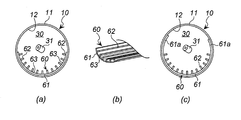
- FIG. 3B is a partial perspective view of a gas flow path forming member used in FIG. In (c), it is radial direction sectional drawing of the gas generator which uses the gas flow path formation member different from (a).
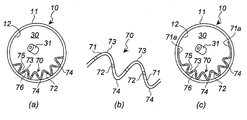
- 4A is a radial cross-sectional view of a gas generator according to still another embodiment in FIG. 4A
- FIG. 4B is a partially enlarged view of a gas flow path forming member used in FIG.
- FIG. 5 is an axial sectional view of a gas generator according to still another embodiment.
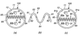
- FIG. 6 is a radial cross-sectional view of FIG. 5 in (a), a partially enlarged view of (a) in (b), and a gas using a gas flow path forming member different from (a) in (c).
- FIG. 3 is a radial cross-sectional view of a generator.
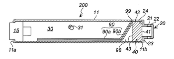
- FIG. 7 is an axial sectional view of a gas generator according to still another embodiment.
- FIG. 8 is a radial cross-sectional view of FIG. 7 in (a), and a partially enlarged view of (a) in (b).
- the present invention provides a simple structure with good ignition combustibility of a gas generant molded body and easy discharge of combustion gas even in an elongated cylindrical housing by means of a solution different from the above prior art. It is an object to provide a gas generator.
- the plurality of grooves serving as gas discharge paths may be formed directly on the inner wall surface of the cylindrical housing (combustion chamber), or may be formed by disposing another member having a groove in the combustion chamber. Also good.
- the plurality of grooves serving as gas discharge paths are adjusted so that the combustion gas generated from the gas generating agent present on the ignition means side can flow to the diffuser section.
- the plurality of grooves serving as gas discharge paths may be continuously formed over the entire length of the combustion chamber, but should be continuously formed in a range of 10 to 100% with respect to the total length of the combustion chamber. It is preferably 30 to 100%, more preferably 40 to 100%, and particularly preferably 80 to 100%. When the length of the plurality of grooves serving as the gas discharge path is 100%, the length is continuous from the ignition means to the diffuser portion.
- the groove can also be formed in a range from the ignition means side to the front of the diffuser portion (not reaching the diffuser portion).
- the plurality of grooves serving as the gas discharge paths may be formed over the entire circumference, but are preferably formed in the range of 1/4 to 3/4, preferably 1/4 to 1/2. More preferably, it is formed in the range.
- channel may be divided
- the interval in the width direction of the grooves is adjusted to be smaller than the minimum length of the gas generant molded body. Since a well-known thing can be used for a gas generating agent molded object, a shape is not restrict
- the members are, for example, the ignition means and the diffuser portion from both sides in the axial direction of the housing (when another member is present in front of the diffuser portion) , And the member).
- the combustion chamber provided inside is also elongated.
- the elongated combustion chamber is filled with no gap so that a required amount of the gas generant molded body does not move.
- the gas generating agent molded body facing the ignition means is ignited and combusted, and the combustion proceeds in the direction toward the diffuser portion.
- the combustion gas generated by the combustion of the gas generant molded body moves from the ignition means side to the diffuser part side through a plurality of grooves serving as gas discharge paths. Even if the gas generant molded body is present on the diffuser part side in the combustion chamber, the outflow of the combustion gas is good and the gas is not blocked.
- the ignition / combustibility of the entire gas generant molded body filled in the combustion chamber is also improved. Therefore, it is possible to increase the volume of the combustion chamber (the volume that can be filled with the gas generating agent molded body) while ensuring the minimum cross-sectional area of the gas discharge path.
- the gas discharge path can be formed relatively easily, and the shape of the parts used for it can be simplified.
- Preferred embodiment 1 of the present invention is the gas generator according to the present invention, wherein the plurality of grooves serving as the gas discharge path are grooves formed on an inner wall surface of the cylindrical housing.
- a plurality of grooves serving as gas discharge paths are formed on the inner wall surface of the cylindrical housing, separate members are not used to form a plurality of grooves serving as gas discharge paths. If a plurality of grooves serving as gas discharge paths are formed on the inner wall surface of the cylindrical housing, the strength of the portion where the grooves are formed may be reduced, so the cylindrical housing of the portion where the grooves are formed The thickness can be increased.
- a preferred embodiment 2 of the present invention is as follows.
- a plurality of grooves serving as the gas discharge path are formed by a gas flow path forming member,
- the gas flow path forming member has a rectangular planar shape, and a cross-sectional shape in the width direction is an arc shape or a cylindrical shape including an uneven portion only on one surface side,
- the interval between adjacent convex portions in the concave and convex portions is adjusted to be shorter than the minimum length of the gas generant molded body,
- the gas flow path forming member is disposed along an inner peripheral wall surface of the cylindrical housing.
- the gas flow path forming member functions as a groove whose concave and convex portions serve as a gas discharge path.
- the gas flow path forming member may include a portion having no unevenness as long as it has unevenness.
- the gas flow path forming member is an arc of about 1/2 to 3/4 round, It is possible to use one having irregularities formed in the entire width direction, or a portion having irregularities in the range of 1/4 to 1/2 circumference, and the remainder having no irregularities formed. it can.
- Unevenness is formed in the range of 1/4 to 3/4, preferably 1/4 to 1/2, and the remainder can be used without unevenness.
- the gas flow path forming member can be easily attached by being inserted along the inner peripheral wall surface of the cylindrical housing (combustion chamber).
- the gas flow path forming member disposed in the combustion chamber can be fixed so as to be sandwiched from both sides in the circumferential direction by, for example, protrusions formed on the inner peripheral wall surface side.
- the gas generating agent molded body facing the ignition means is ignited and combusted, and the combustion proceeds in the direction toward the diffuser portion.
- the combustion gas generated by the combustion of the gas generant compact passes through a plurality of grooves (unevenness of the gas flow path forming member) serving as a gas discharge path from the ignition means side. Since it moves to the diffuser part side, the outflow property of the combustion gas is good, and at the same time, the ignition combustibility of the entire gas generant molded body filled in the combustion chamber is improved.
- Preferred embodiment 3 of the present invention is as follows: A plurality of grooves serving as the gas discharge path are formed by a gas flow path forming member,
- the gas flow path forming member has a rectangular planar shape and a cross-sectional shape in the width direction having an arc shape or a cylindrical shape including a corrugated portion, and has a plurality of communication holes penetrating in the thickness direction in the corrugated portion.
- Has The interval between adjacent vertex portions of the corrugated portion is adjusted to be shorter than the minimum length of the gas generant molded body,
- the gas flow path forming member is disposed along an inner peripheral wall surface of the cylindrical housing.
- the gas flow path forming member functions as a groove whose corrugated portion serves as a gas discharge path.
- the portion including the apex of the waveform portion is a rounded curved surface, but may be a curved surface having an angle (an angle formed by an acute angle).
- the waveform portion may be a quadrangle such as a trapezoid, a square, or a rectangle.
- the gas flow path forming member may include a portion having no waveform as long as it has a waveform.
- the gas flow path forming member is an arc of about 1/2 to 3/4 round, It is possible to use the one where the waveform is formed in the entire width direction, or the portion where the waveform is formed is in the range of 1/4 to 1/2 lap, and the rest is not formed with the waveform. it can.
- the gas flow path forming member has a cylindrical shape, The corrugated portion is formed in the range of 1/4 to 3/4 rounds, preferably in the range of 1/4 to 1/2 rounds, and the rest can be formed with no waveform.
- the gas flow path forming member can be easily attached by being inserted along the inner peripheral wall surface of the cylindrical housing (combustion chamber).
- the gas flow path forming member disposed in the combustion chamber can be fixed so as to be sandwiched from both sides in the circumferential direction by, for example, protrusions formed on the inner peripheral wall surface side.
- the groove (inner groove) formed by the corrugated portion facing the combustion chamber side and the opposite side (inner circumference of the cylindrical housing) A groove (outer groove) formed by a corrugated portion facing the wall surface side is formed.
- channel are connected by the some communication hole penetrated in the thickness direction in the waveform part. For this reason, the combustion gas generated in the combustion chamber during operation moves through the inner groove, and enters the outer groove through a plurality of communication holes formed in the corrugated portion. Enter the inside groove.
- the gas flow path forming member including the corrugated portion can be manufactured, for example, by molding a perforated plate into an arc shape or a cylindrical shape having the corrugated portion by press working.
- a preferred embodiment 4 of the present invention is as follows.
- a plurality of grooves serving as the gas discharge path are formed by a gas flow path forming member,
- the gas flow path forming member has a cross-sectional shape in the width direction including a corrugated portion, and has a plurality of communication holes penetrating in the thickness direction in the corrugated portion, The interval between adjacent vertex portions of the corrugated portion is adjusted to be shorter than the minimum length of the gas generant molded body,
- the gas generator according to the present invention wherein the gas flow path forming member is arranged along the length direction of the cylindrical housing so as to divide the inside of the cylindrical housing into two in the length direction.
- the gas flow path forming member functions as a groove whose corrugated portion serves as a gas discharge path.
- the gas flow path forming member may include a portion having no corrugation as long as it has a corrugation, and the following form may be used. it can.
- IV A gas flow path forming member according to (II), wherein the gas flow path forming member has curved surfaces extending in different directions or in the same direction on both end sides and contacting the inner peripheral wall surface.
- the gas flow path forming member is arranged to divide the inside of the cylindrical housing (combustion chamber) into two along the length direction.
- the volume ratio of the two combustion chambers divided into two is not limited, but is preferably divided into two so that the volumes are approximately the same.
- the gas flow path forming member is arranged so as to divide the inside of the cylindrical housing (combustion chamber) into two along the length direction, so that a groove (first) is formed by the corrugated portion facing the first combustion chamber side. 1 groove) and a groove (second groove) formed by a corrugated portion facing the second combustion chamber. And the 1st groove
- the gas flow path forming member including the corrugated portion can be manufactured, for example, by molding a porous plate so as to have the corrugated portion by press working.
- a preferred embodiment 5 of the present invention is as follows.
- a plurality of grooves serving as the gas discharge path are formed by a gas flow path forming member,
- the gas flow path forming member is The planar shape is rectangular,
- the side surface consists of a flat plate portion and an inclined plate portion formed on the diffuser portion side,
- the cross-sectional shape in the width direction is an arc shape including a corrugated portion, and has a plurality of communication holes penetrating in the thickness direction in the corrugated portion, The interval between adjacent vertex portions of the corrugated portion is adjusted to be shorter than the minimum length of the gas generant molded body,
- the gas flow path forming member is disposed along the inner peripheral wall surface of the cylindrical housing such that the inclined plate portion is positioned on the diffuser portion side; Between the inclined plate portion and the inner peripheral wall surface of the cylindrical housing, there is a space in which the cross-sectional shape in the axial direction is a triangle and is not filled with the gas generant molded body. It is a
- the gas flow path forming member functions as a groove whose corrugated portion serves as a gas discharge path.
- the gas flow path forming member may include a portion having no waveform as long as it has a waveform. Particularly in the flat plate portion, when the gas flow path forming member is an arc of about 1/2 to 3/4 rounds, Use a corrugated part formed in the entire width direction, or a part where the corrugated part is formed is in the range of 1/4 to 1/2 lap, and the rest has no corrugated part. be able to.
- the gas flow path forming member can be easily attached by inserting the flat plate portion along the inner peripheral wall surface of the cylindrical housing (combustion chamber) so that the inclined plate portion is positioned on the diffuser portion side. Between the inclined plate portion and the inner peripheral wall surface of the cylindrical housing, there is a space (triangular space) that has a triangular cross-sectional shape in the axial direction and is not filled with the gas generant molded body.
- the gas flow path forming member disposed in the combustion chamber can be fixed so as to be sandwiched from both sides in the circumferential direction by, for example, protrusions formed on the inner peripheral wall surface side.
- the groove (inner groove) formed by the corrugated portion facing the combustion chamber side and the opposite side (inner circumference of the cylindrical housing) A groove (outer groove) formed by a corrugated portion facing the wall surface side is formed.
- channel are connected by the some through-hole formed in the thickness direction in the waveform part. For this reason, the combustion gas generated in the combustion chamber during operation moves through the inner groove, and enters the outer groove through a plurality of communication holes formed in the corrugated portion. Enter the inside groove.
- Preferred embodiment 6 of the present invention includes In the cylindrical housing, a filter is disposed between the diffuser portion and a combustion chamber filled with the gas generating agent molded body, or any one of the above-described present invention or preferred embodiments 1 to 5 of the present invention. It is a gas generator.
- the filter has a combustion gas filtering function and a cooling function, and a known gas generator filter can be used.
- Preferred embodiment 7 of the present invention is as follows: In the cylindrical housing, a filter is disposed between the diffuser portion and the combustion chamber filled with the gas generant molded body, The gas according to any one of the above aspects of the present invention or the preferred aspects 1 to 5 of the present invention, in which a partition wall having a through hole is disposed between the filter and the combustion chamber in the axial direction with respect to the filter. Generator.
- a partition wall is disposed between the filter and the combustion chamber. Since the partition wall and the filter are spaced apart in the axial direction, a space is formed between them. With such a space, when the combustion gas flows into the space from the combustion chamber through the partition wall, the combustion gas will pass evenly over the entire surface of the filter. The function is easily exhibited. In addition, when the gas generator which has the above-mentioned triangular space is used, since the inclination board part of a gas flow path formation member acts the same as a partition, a partition is unnecessary.
- the entire gas generant molded body in the combustion chamber is easily ignited and combusted.
- the gas generator 10 has an electric igniter 15 as an ignition means attached to one end 11a side of a cylindrical housing 11, and the other end 11b side.
- a diffuser section 20 having a gas discharge port 21 is attached.
- the gas discharge port 21 is closed from the inside with a metal tape such as aluminum.
- the cylindrical housing 11 and the diffuser part 20 are made of metal such as iron.
- the electric igniter 15 is used in a known gas generator.
- the diffuser part 20 has a cup part 22 and a flange part 23, and the flange part 23 is welded and fixed to the cylindrical housing end (other end) 11 b. Between the cylindrical housing 11 and the diffuser portion 20, an annular step portion 24 formed of an annular surface of the flange portion 23 is formed.
- a slender combustion chamber 30 is formed between the igniter 15 and the diffuser portion 20 in the cylindrical housing 11, and a required amount of a gas generant molded body 31 is filled without a gap. .
- a disk-shaped filter 40 and a cup-shaped partition wall 45 are disposed between the combustion chamber 30 and the diffuser portion 20.
- the filter 40 is disposed in a state where one end surface 41 on the diffuser portion 20 side is in contact with the annular step portion 24 and the peripheral surface 42 is in contact with the inner peripheral wall surface 12 of the cylindrical housing.
- a cup-shaped partition wall 45 is in contact with the other end surface 43 of the filter 40 at the opening.
- the cup-shaped partition 45 includes a bottom surface 46 and a peripheral surface 47, and the bottom surface 46 and the peripheral surface 47 have a plurality of through holes 46a and a plurality of through holes 47a, respectively.
- the cup-shaped partition wall 45 is not filled with the gas generant molded body 31, and a disk-shaped space exists.
- a groove 50 that is continuous in the axial direction is formed in a part of the inner peripheral wall surface 12 of the cylindrical housing in which the combustion chamber 30 and the cup-shaped partition wall 45 are arranged.
- the groove 50 becomes a gas discharge path.
- the groove 50 is formed in the entire range of the length L of the combustion chamber 30, and is also formed in a portion that contacts the peripheral surface 47 of the cup-shaped partition wall 45.
- the groove 50 can be formed in the entire range of the length L of the combustion chamber 30 (from the electric igniter 15 to the bottom surface 46 of the cup-shaped partition wall 45). At this time, the peripheral surface 47 of the cup-shaped partition wall 45 is formed. This through-hole 47a becomes unnecessary.
- a plurality of grooves 50 (five in FIG.
- the width of the groove 50 is adjusted to be shorter than the minimum length of the gas generant molded body 31. Since the minimum length of the gas generant molded body 31 shown in FIGS. 1 and 2 is a diameter, the width of the groove 50 is adjusted to be smaller than the diameter. For this reason, the gas generating agent molded body 31 does not enter the groove 50 and block the gas discharge path.
- the operation of the gas generator 10 shown in FIGS. 1 and 2 will be described.
- the igniter 15 When the igniter 15 is actuated, the portion of the gas generant molded body 31 in contact with the igniter 15 is ignited and combusted, and the combustion sequentially proceeds toward the diffuser portion 20.
- the combustion gas generated by the combustion of the gas generant molded body 31 moves from the igniter 15 side to the diffuser portion 20 side through the plurality of grooves 50 serving as gas discharge paths, and the movement process.
- the gas generating agent molded body 31 facing the groove 50 is ignited and burned.
- the combustion gas in the combustion chamber 30 enters the space in the cup-shaped partition wall 45 through the through hole 46a in the bottom surface 46 of the cup-shaped partition wall, and a part of the combustion gas passing through the groove 50 is a peripheral surface of the cup-shaped partition wall.
- the inside of the cup-shaped partition wall 45 also enters through the 47 through holes 47a.
- the combustion gas that has entered the space in the cup-shaped partition wall 45 passes through the entire surface of the filter 40, is filtered and cooled, then enters the diffuser unit 20, and is discharged from the gas discharge port 21.
- the through-hole 47a is formed in the surrounding surface 47 of a cup-shaped partition wall over the perimeter at equal intervals, it is a case where the cup-shaped partition wall 47 is rotated by vibration applied to the gas generator 10. In addition, any one of the through holes 47 a can maintain the state facing the groove 50.
- a plurality of grooves 50 are formed as a group on a part of the inner peripheral wall surface 12 (a range of 1 ⁇ 2 or less of the entire circumference). May be formed separately at a plurality of locations on the inner peripheral wall surface 12.
- the gas generator shown in FIGS. 1 and 2 can ensure a wide combustion chamber 30 serving as a filling space for the gas generant molded body 31 while maintaining a gas discharge path.
- FIGS. 1 and 3 In the gas generator 10 in FIG. 1, instead of forming a plurality of grooves 50 in the inner peripheral wall surface 12 of the cylindrical housing 11, the inside of the cylindrical housing 11 A gas flow path forming member 60 shown in FIGS. 3A and 3B can be disposed on the peripheral wall surface 12.
- the gas flow path forming member 60 has a plurality of convex portions 62 formed in the axial direction (along the length direction of the cylindrical housing 11) with a circumferential interval only on one surface side of the circular arc substrate 61. is doing.
- a plurality of grooves (concave portions) 63 continuous in the axial direction are formed between the plurality of convex portions 62 in the circumferential direction, and the grooves 63 serve as a gas discharge path.
- the width of the arc-shaped substrate 61 of the gas flow path forming member 60 is adjusted to be in the range of about 1/3 to 1/2 of the entire circumference of the cylindrical housing 10. Yes.
- the interval between the adjacent convex portions 62 is adjusted to be shorter than the minimum length of the gas generant molded body 31.
- the planar shape of the gas flow path forming member 60 is a rectangle and can be in the same length range as the groove 50 shown in FIG. As shown in FIG. 3C, the gas flow path forming member 60 forms a convex portion 62 in a partial range on one surface side of the arc-shaped substrate 61, and a curved surface portion 61a on which the convex portion 62 is not formed. It may have.
- the gas flow path forming member 60 is disposed such that the surface of the arc-shaped substrate 61 where the convex portion 62 is not formed is along the inner peripheral wall surface 12 of the cylindrical housing. For example, one end of the gas flow path forming member 60 on the igniter 15 side is in contact with the igniter 15, and the opposite end is in contact with the other end surface 43 of the filter 40 so as to be fixed.
- the operation of the gas generator 10 shown in FIGS. 1 and 3 will be described.
- the igniter 15 When the igniter 15 is actuated, the portion of the gas generant molded body 31 in contact with the igniter 15 is ignited and combusted, and the combustion sequentially proceeds toward the diffuser portion 20.
- the combustion gas generated by the combustion of the gas generant molded body 31 moves from the igniter 15 to the diffuser portion 20 through the plurality of grooves 63 serving as gas discharge paths, and in the movement process, the grooves
- the gas generating agent molded body 31 facing 63 is ignited and burned.
- the combustion gas in the combustion chamber 30 enters the space in the cup-shaped partition wall 45 through the through hole 46a in the bottom surface 46 of the cup-shaped partition wall, and part of the combustion gas that has passed through the groove 63 is surrounded by the periphery of the cup-shaped partition wall.
- the space in the cup-shaped partition wall 45 also enters through the through hole 47 a of the surface 47.
- the combustion gas that has entered the space in the cup-shaped partition wall 45 passes through the entire surface of the filter 40, is filtered and cooled, then enters the diffuser unit 20, and is discharged from the gas discharge port 21.
- the through-hole 47a is formed in the surrounding surface 47 of a cup-shaped partition wall over the perimeter at equal intervals, it is a case where the cup-shaped partition wall 47 is rotated by vibration applied to the gas generator 10. In addition, any of the through holes 47 a can maintain the state facing the groove 63.
- the arc-shaped substrate 61 is brought into contact with the inner peripheral wall surface 12.
- the arc-shaped substrate 61 is provided with a plurality of holes having a size that does not allow the gas generant molded body to pass therethrough, and the convex portion 62 is formed on the inner peripheral wall surface. 12, the space between the convex portion 62 and the inner peripheral wall surface 12 can be used as a combustion gas discharge path (groove 63).
- FIGS. 1 and 4 In the gas generator 10 in FIG. 1, instead of forming a plurality of grooves 50 on the inner peripheral wall surface 12 of the cylindrical housing 11, FIG. A gas flow path forming member 70 shown in (b) can be used.
- the 4A and 4B has a rectangular planar shape, and has a corrugated substrate 71 and a plurality of communication holes 72 penetrating in the thickness direction of the corrugated substrate 71. It is what.
- the communication hole 72 is formed on the surface excluding the one surface side vertex 73 and the other surface side vertex 74 of the corrugated substrate 71. However, the communication hole 72 can also be formed in the one surface side vertex 73.
- the width of the corrugated substrate 71 of the gas flow path forming member 70 is adjusted to be about 1/3 of the entire circumference of the cylindrical housing 10.
- the interval between adjacent vertices 73 is adjusted to be shorter than the minimum length of the gas generant molded body 31.
- the corrugated substrate 71 has an arc shape that can follow the inner wall surface 12 of the cylindrical housing as a whole.
- the gas flow path forming member 70 can also form a curved surface portion 71 a having no corrugation on both end sides of the corrugated substrate 71 as shown in FIG.
- the curved surface portion 71 a is in contact with the inner peripheral wall surface 12 of the cylindrical housing 11.
- the gas flow path forming member 70 is disposed in a state where the other surface side apex 74 is in contact with the inner peripheral wall surface 12 of the cylindrical housing. For this reason, an inner groove 75 formed by the corrugated substrate 71 facing the combustion chamber 30 side and an outer groove 76 formed by the corrugated substrate 71 facing the opposite side (the inner peripheral wall surface 12 side of the cylindrical housing) are provided. is doing. The inner groove 75 and the outer groove 76 are communicated with each other by a plurality of communication holes 72 formed in the thickness direction in the corrugated substrate 71.
- the combustion gas generated in the combustion chamber 30 during operation moves in the axial direction through the inner groove 75 and enters the outer groove 76 from the plurality of communication holes 72 formed in the corrugated substrate 71.
- the combustion gas that has entered the outer groove 76 enters the inner groove 75 again.
- the combustion gas repeatedly enters and exits from the inner groove 75 to the outer groove 76 and from the outer groove 76 to the inner groove 75, so that ignition combustion of the entire gas generant molded body 31 in the combustion chamber 30 is promoted.
- the combustion residue in the combustion gas is also attached to the gas flow path forming member 70 and is easily captured.
- a plurality of such gas flow path forming members 70 may be arranged along the inner peripheral wall surface 12 in the circumferential direction.
- FIGS. 5 and 6 The gas generator 100 shown in FIG. 5 is formed with a plurality of grooves 50 on the inner peripheral wall surface 12 of the cylindrical housing 11 in the gas generator 10 shown in FIG. Instead, a gas flow path forming member 80 shown in FIGS. 6A and 6B is disposed as shown in FIG. However, the cup-shaped partition wall 45 used in the gas generator 100 of FIG. 5 does not have the through hole 47a on the peripheral surface 47.
- the gas flow path forming member 80 shown in FIGS. 6A and 6B has a rectangular planar shape and includes a corrugated substrate 81 and a plurality of communication holes 82 penetrating in the thickness direction of the corrugated substrate 81. It is what.
- the communication hole 82 is formed on the surface excluding the one surface side vertex 83 and the other surface side vertex 84 of the corrugated substrate 81, but may be formed also on the one surface side vertex 83 and the other surface side vertex 84.
- the intervals between the adjacent vertices 83 and the adjacent vertices 84 are adjusted to be shorter than the minimum length of the gas generant molded body 31.
- the corrugated substrate 81 has an apex 83 and an apex 84 that fall within a certain range as a whole, but as a whole has an arc shape as shown in FIG. 4 (a). It may be.
- the gas flow path formation member 80 forms the curved surface part 81a without a waveform in the both ends of the waveform board
- One end side of the gas flow path forming member 80 is in contact with the bottom surface 46 of the cup-shaped partition wall, and both ends in the width direction are in contact with the inner peripheral wall surface 12 of the cylindrical housing 11 (combustion chamber 30). Are arranged in two along the length direction. Since the gas generating agent molded body 31 is filled in the combustion chamber 30 without a gap, the gas flow path forming member 80 is supported by the gas generating agent molded body 31. Further, the gas flow path forming member 80 can also be supported by struts having a porous (combustion gas passage hole) in contact with the inner peripheral wall surface 12 at both ends in the length direction.
- combustion chamber 30 is divided into a first combustion chamber 30 a and a second combustion chamber 30 b by a gas flow path forming member 80.
- a first groove 85 formed by a recess between adjacent vertices 83 of the corrugated substrate 81 is formed on the first combustion chamber 30a side.
- a second groove 86 formed by a recess between adjacent vertices 84 of the corrugated substrate 81 is formed on the first combustion chamber 30b side.
- the first groove 85 and the second groove 86 are communicated with each other by a plurality of communication holes 82 penetrating in the thickness direction in the corrugated substrate 81.
- the combustion gas generated in the combustion chamber 30 (the first combustion chamber 30a and the second combustion chamber 30b) during operation moves in the axial direction through the first groove 85 and the second groove 86, and the corrugated substrate.
- the second groove 86 is entered, and after entering the second groove 86, the first groove 85 is entered.
- the combustion gas repeatedly enters and exits from the first groove 85 to the second groove 86 and from the second groove 86 to the first groove 85, so that ignition combustion of the entire gas generant molded body 31 in the combustion chamber 30 occurs. Promoted. Note that the groove 50 shown in FIG.
- the gas flow path forming member 70 shown in FIG. 4 can also be arranged.
- the through hole 47a can be formed in the peripheral surface 47 of the cup-shaped partition wall 45 in the same manner as in FIG.
- a gas generator 200 shown in FIG. 7 is formed with a plurality of grooves 50 on the inner peripheral wall surface 12 of the cylindrical housing 11 in the gas generator 10 shown in FIG. Instead, a gas flow path forming member 90 is arranged as shown in FIG. However, in the gas generator 200 shown in FIG. 7, the cup-shaped partition wall 45 is not used.
- the gas flow path forming member 90 has a rectangular planar shape, and a side surface shape is composed of a flat plate portion 90a and an inclined plate portion 90b formed on one end side.
- the cross-sectional shapes in the width direction of the flat plate portion 90a and the inclined plate portion 90b of the gas flow path forming member 90 are as shown in FIGS. 8 (a) and 8 (b), which are shown in FIGS. 4 (a) and 4 (b). It has the same structure.
- the gas flow path forming member 90 has a corrugated substrate 91 and a plurality of communication holes 92 penetrating in the thickness direction of the corrugated substrate 91.
- the communication hole 92 is formed on the surface excluding the one surface side vertex 93 and the other surface side vertex 94 of the corrugated substrate 91.
- the communication hole 92 can be formed in the one surface side vertex 93 of the flat plate portion 90a, and the communication hole 92 can also be formed in the one surface side vertex 93 and the other surface side vertex 94 of the inclined plate portion 90b.
- the interval between adjacent vertices 93 is adjusted to be shorter than the minimum length of the gas generant molded body 31.
- the corrugated substrate 91 of the flat plate portion 90a has an arc shape that can follow the inner peripheral wall surface 12 of the cylindrical housing as a whole.
- the inclined plate portion 90b has the same shape as the flat plate portion 90a.
- the gas flow path forming member 90 can also have a cross-sectional shape as shown in FIG.
- the flat plate portion 90a of the gas flow path forming member 90 is arranged in a state where the other surface side apex 94 is in contact with the inner peripheral wall surface 12 of the cylindrical housing. For this reason, an inner groove 95 formed by the corrugated substrate 91 facing the combustion chamber 30 side and an outer groove 96 formed by the corrugated substrate 91 facing the opposite side (the inner peripheral wall surface 12 side of the cylindrical housing) are provided. is doing. Further, the inclined plate portion 90b of the gas flow path forming member 90 is disposed in a state where the arcuate tip 99 is in contact with the boundary portion between the filter 40 and the inner peripheral wall surface 12 of the cylindrical housing.
- the triangular space 98 corresponds to a space formed by the cup-shaped partition wall 45 and the filter 40 in the gas generator 10 of FIG.
- the inner groove 95 and the outer groove 96 are communicated by a plurality of communication holes 92 formed in the thickness direction in the corrugated substrate 91. Therefore, the combustion gas generated in the combustion chamber 30 during operation moves in the axial direction through the inner groove 95 and enters the outer groove 96 from the plurality of communication holes 92 formed in the corrugated substrate 91. The combustion gas that has entered the outer groove 96 enters the inner groove 95 again. In this way, the combustion gas repeatedly enters and exits from the inner groove 95 to the outer groove 96 and from the outer groove 96 to the inner groove 95, so that ignition combustion of the entire gas generant molded body 31 in the combustion chamber 30 is promoted.
- the combustion gas generated in the combustion chamber 30 flows into the triangular space 98 through the gas flow path forming member 90, the combustion gas is filtered and cooled by passing through the entire surface of the filter 40, and then the diffuser portion. 20 enters and is discharged from the gas discharge port 21.
- the gas generator of the present invention is not limited to these embodiments as long as a predetermined effect can be obtained.
Landscapes
- Engineering & Computer Science (AREA)
- Mechanical Engineering (AREA)
- Physics & Mathematics (AREA)
- Fluid Mechanics (AREA)
- General Engineering & Computer Science (AREA)
- Air Bags (AREA)
- Feeding, Discharge, Calcimining, Fusing, And Gas-Generation Devices (AREA)
Abstract
Description
ガス発生剤をガス源とするガス発生器の中には、細長い筒状のハウジングを使用したものが汎用されている。
このような筒状ハウジングを使用した場合、ガス発生剤が充填された燃焼室も細長い形状のものとなるため、ガス発生剤の燃焼性が重要となる。
JP-A No.2013-184482には、筒状ハウジング10内に板状の仕切部材20が配置され、ガス発生剤充填空間38とガス流路空間40の2室に分離されたガス発生器が開示されている。
いずれの発明のガス発生器も、燃焼室内のガス発生剤の着火燃焼性が向上されている。
本発明は、
一端側に点火手段が取り付けられ、他端側にガス排出口を有するディフューザ部が取り付けられた筒状ハウジングを有しており、
前記筒状ハウジング内の残部空間内においてガス発生剤成形体が充填された燃焼室を有しているガス発生器であって、
前記燃焼室が、ガス排出経路となる複数の溝を有しており、
前記ガス排出経路となる複数の溝が、前記筒状ハウジングの長さ方向に連続した溝が周方向に複数形成されたものであり、
前記溝の幅方向の間隔が、前記ガス発生剤成形体の最小長さよりも短くなるように調整されており、
作動時において、前記ガス発生剤成形体が燃焼して発生した燃焼ガスが前記ガス排出経路となる溝に沿って移動して、ディフューザ部のガス排出口から排出されるものである、ガス発生器を提供する。
本発明は、上記従来技術とは異なる解決手段によって、細長い筒状ハウジングであっても、単純な構造でガス発生剤成形体の着火燃焼性が良く、燃焼ガスも排出されやすいガス発生器を提供することを課題とする。
ガス排出経路となる複数の溝は、燃焼室の全長にわたって連続的に形成されていてもよいが、燃焼室の全長に対して10~100%の範囲で連続的に形成されるようにすることができ、好ましくは30~100%であり、より好ましくは40~100%であり、特に好ましくは80~100%である。
ガス排出経路となる複数の溝の長さが100%であるときは、点火手段からディフューザ部まで連続した長さを有するものである。
燃焼室の全長にわたって(前記の溝の長さが100%の場合)ガス排出経路となる複数の溝を形成しないときは、ガス発生剤成形体の着火燃焼が容易である点火手段側には溝を形成せず、ディフューザ部側には溝を形成することができるほか、点火手段側からディフューザ部の手前までの(ディフューザ部まで到達しない)範囲に溝を形成することもできる。
また、複数の溝からなるガス排出経路の群が、筒状ハウジングの内周壁面に円周方向に複数個所に分かれて形成されていてもよい。
ガス発生剤成形体は公知のものを使用することができるため、形状も特に制限されず、ディスク状、円柱状などにすることができる。
このため、溝の幅方向の間隔を上記長さに調整することで、ガス発生剤成形体の形状に拘わらず、溝内部にガス発生剤成形体が入り込んで、ガス排出経路を塞ぐことが防止される。
そして、細長い形状の燃焼室内には、所要量のガス発生剤成形体が動くことがないように隙間なく充填されている。
作動時には、点火手段側に面したガス発生剤成形体から着火燃焼され、順次ディフューザ部方向に燃焼が進行して行く。
このような燃焼過程において、ガス発生剤成形体の燃焼により発生した燃焼ガスは、ガス排出経路となる複数の溝を通って、点火手段側からディフューザ部側へと移動して行くため、未燃焼のガス発生剤成形体が燃焼室内のディフューザ部側に存在しても燃焼ガスの流出性が良く、ガスが閉塞することがない。
同時に燃焼室内に充填されたガス発生剤成形体全体の着火燃焼性も向上されることになる。
したがって、ガス排出経路の断面積を最小限確保しながら、燃焼室の容積(ガス発生剤成型体を充填することができる容積)を大きくすることができる。また、ガス排出経路の形成を比較的容易に行うことができ、それに使用される部品の形状も単純となる。
筒状ハウジングの内壁面にガス排出経路となる複数の溝が形成されていると、溝が形成されている部分の強度が低下することも考えられるため、溝が形成された部分の筒状ハウジングの厚みを厚くすることもできる。
前記ガス排出経路となる複数の溝がガス流路形成部材により形成されたものであり、
前記ガス流路形成部材が、平面形状が長方形で、幅方向の断面形状が一面側のみに凹凸部分を含む円弧形状乃至は筒形状のものであり、
前記凹凸部分における隣接する凸部間の間隔が、前記ガス発生剤成形体の最小長さよりも短くなるように調整されているものであり、
前記ガス流路形成部材が、前記筒状ハウジングの内周壁面に沿って配置されている、上記本発明のガス発生器である。
本発明の好ましい態様では、ガス流路形成部材は、凹凸を有しているものであれば、凹凸がない部分を含んでいるものでもよい。
ガス流路形成部材が1/2周~3/4周程度の円弧であるとき、
幅方向の全部に凹凸が形成されているもの、または
凹凸が形成されている部分が1/4周~1/2周の範囲であり、残部は凹凸が形成されていないものを使用することができる。
ガス流路形成部材が筒形状であるとき、
凹凸が1/4周~3/4周の範囲、好ましくは1/4周~1/2周の範囲に形成されており、残部は凹凸が形成されていないものを使用することができる。
燃焼室に配置されたガス流路形成部材は、例えば内周壁面側に形成された突起により周方向の両側から挟み付けられるようにして固定することができる。
このような燃焼過程において、ガス発生剤成形体の燃焼により発生した燃焼ガスは、ガス排出経路となる複数の溝(ガス流路形成部材が有している凹凸)を通って、点火手段側からディフューザ部側へと移動して行くため、燃焼ガスの流出性が良く、同時に燃焼室内に充填されたガス発生剤成形体全体の着火燃焼性も向上されることになる。
前記ガス排出経路となる複数の溝がガス流路形成部材により形成されたものであり、
前記ガス流路形成部材が、平面形状が長方形で、幅方向の断面形状が波形部分を含む円弧形状乃至は筒形状のもので、前記波形部分において厚さ方向に貫通された複数の連通孔を有しているものであり、
前記波形部分の隣接する頂点部分間の間隔が、前記ガス発生剤成形体の最小長さよりも短くなるように調整されているものであり、
前記ガス流路形成部材が、前記筒状ハウジングの内周壁面に沿って配置されている、上記本発明のガス発生器である。
波形部分の頂点を含む部分は丸みを帯びた曲面であるが、角(鋭角からなる角)を有する曲面であってもよい。その他、波形部分が、台形、正方形、長方形などの四角形からなるものでもよい。
本発明の好ましい態様では、ガス流路形成部材は、波形を有しているものであれば、波形がない部分を含んでいるものでもよい。
ガス流路形成部材が1/2周~3/4周程度の円弧であるとき、
幅方向の全部に波形が形成されているもの、または
波形が形成されている部分が1/4周~1/2周の範囲であり、残部は波形が形成されていないものを使用することができる。
ガス流路形成部材が筒形状であるとき、
波形部分が1/4周~3/4周の範囲、好ましくは1/4周~1/2周の範囲に形成されており、残部は波形が形成されていないものを使用することができる。
燃焼室に配置されたガス流路形成部材は、例えば内周壁面側に形成された突起により周方向の両側から挟み付けられるようにして固定することができる。
そして、内側溝と外側溝は、波形部分において厚さ方向に貫通された複数の連通孔により連通されている。
このため、作動時に燃焼室内で発生した燃焼ガスは、内側溝を通って移動すると共に、波形部分に形成された複数の連通孔から外側溝に入ったり、さらに外側溝に入った燃焼ガスは再度内側溝に入ったりする。
このように内側溝から外側溝、外側溝から内側溝への燃焼ガスの出入りが繰り返されることから、燃焼室内におけるガス発生剤成形体全体の着火燃焼が促進されると共に、燃焼ガス中の燃焼残渣もガス流路形成部材に付着されて捕捉されやすくなる。
波形部分を含むガス流路形成部材は、例えば多孔板をプレス加工により波形部分を有する円弧形状乃至は筒形状に成形加工することで製造することができる。
前記ガス排出経路となる複数の溝がガス流路形成部材により形成されたものであり、
前記ガス流路形成部材が、幅方向の断面形状が波形部分を含んでいるもので、前記波形部分において厚さ方向に貫通された複数の連通孔を有しているものであり、
前記波形部分の隣接する頂点部分間の間隔が、前記ガス発生剤成形体の最小長さよりも短くなるように調整されているものであり、
前記ガス流路形成部材が、前記筒状ハウジング内を長さ方向に二分割するように筒状ハウジングの長さ方向に沿って配置されている、上記本発明のガス発生器である。
本発明の好ましい態様では、のガス流路形成部材は、波形を有しているものであれば、波形がない部分を含んでいるものでもよく、次のような形態のものを使用することができる。
(I)波形の両面側の凸部分が高さ方向に一定幅に収まっているガス流路形成部材。即ち、全体が一定幅の長方形内に収まっているガス流路形成部材。
(II)全体が円弧形状の波形であるガス流路形成部材。
(III)(I)のガス流路形成部材であって、両端側に異なる方向または同じ方向に延び、内周壁面に当接する曲面を有しているガス流路形成部材。
(IV)(II)のガス流路形成部材であって、両端側に異なる方向または同じ方向に延び、内周壁面に当接する曲面を有しているガス流路形成部材。
そして、第1溝と第2溝は、波形部分において厚さ方向に貫通された複数の連通孔により連通されている。
作動時に燃焼室内で発生した燃焼ガスは、第1溝と第2溝のそれぞれを通って移動すると共に、波形部分に形成された複数の貫通孔を経て、第1溝から第2溝に移動したり、第2溝から第1溝に移動したりする。
このように第1溝から第2溝、第2溝から第1溝への燃焼ガスの出入りが繰り返されることから、燃焼室内におけるガス発生剤成形体全体の着火燃焼が促進される。
波形部分を含むガス流路形成部材は、例えば多孔板をプレス加工により波形部分を有するように成形加工することで製造することができる。
前記ガス排出経路となる複数の溝がガス流路形成部材により形成されたものであり、
前記ガス流路形成部材が、
平面形状が長方形状であり、
側面形状が平板部分と前記ディフューザ部側に形成された傾斜板部分からなり、
幅方向の断面形状が波形部分を含む円弧形状で、前記波形部分において厚さ方向に貫通された複数の連通孔を有しているものであり、
前記波形部分の隣接する頂点部分間の間隔が、前記ガス発生剤成形体の最小長さよりも短くなるように調整されているものであり、
前記ガス流路形成部材が、前記傾斜板部分が前記ディフューザ部側に位置するようにして、前記平板部分が前記筒状ハウジングの内周壁面に沿って配置されており、
前記傾斜板部分と前記筒状ハウジングの内周壁面との間には、軸方向の断面形状が三角形である、ガス発生剤成形体が充填されていない空間が存在している、上記本発明のガス発生器である。
本発明の好ましい態様では、ガス流路形成部材は、波形を有しているものであれば、波形がない部分を含んでいるものでもよい。
特に平板部において、ガス流路形成部材が1/2周~3/4周程度の円弧であるとき、
幅方向の全部に波形部分が形成されているもの、または
波形部分が形成されている部分が1/4周~1/2周の範囲であり、残部は波形が形成されていないものを使用することができる。
そして、傾斜板部分と筒状ハウジングの内周壁面との間には、軸方向の断面形状が三角形である、ガス発生剤成形体が充填されていない空間(三角空間)が存在している。
燃焼室に配置されたガス流路形成部材は、例えば内周壁面側に形成された突起により周方向の両側から挟み付けられるようにして固定することができる。
そして、内側溝と外側溝は、波形部分において厚さ方向に形成された複数の貫通孔により連通されている。
このため、作動時に燃焼室内で発生した燃焼ガスは、内側溝を通って移動すると共に、波形部分に形成された複数の連通孔から外側溝に入ったり、さらに外側溝に入った燃焼ガスは再度内側溝に入ったりする。
このように内側溝から外側溝、外側溝から内側溝への燃焼ガスの出入りが繰り返されることから、燃焼室内におけるガス発生剤成形体全体の着火燃焼が促進されると共に、燃焼ガス中の燃焼残渣もガス流路形成部材に付着されて捕捉されやすくなる。
また燃焼室内で発生した燃焼ガスは、ガス流路形成部材の連通孔を経て三角空間内に流入するため、ディフューザ部にガスが流れやすくなる。
前記筒状ハウジング内において、前記ディフューザ部と前記ガス発生剤成形体が充填された燃焼室の間にフィルタが配置されている、上記本発明又は本発明の好ましい態様1から5のいずれか1つのガス発生器である。
前記筒状ハウジング内において、前記ディフューザ部と前記ガス発生剤成形体が充填された燃焼室の間にフィルタが配置されており、
前記フィルタと前記燃焼室の間において前記フィルタと軸方向に間隔をおいて、貫通孔を有する隔壁が配置されている、上記本発明の又は本発明の好ましい態様1から5のいずれか1つのガス発生器である。
このような空間を有していると、燃焼室から隔壁を経て前記空間に燃焼ガスが流入したとき、燃焼ガスはフィルタの全面に対して均等に通過されるようになるため、濾過機能や冷却機能が発揮され易くなる。
なお、上記した三角空間を有するガス発生器を使用した場合には、ガス流路形成部材の傾斜板部分が隔壁と同じ作用をするため、隔壁は不要である。
また、燃焼ガスの排出経路に必要な断面積を最低限維持しながら、ガス発生剤成形体の充填空間(燃焼室の容積)を大きく確保することができる。
(1)図1、図2のガス発生器
ガス発生器10は、筒状ハウジング11の一端11a側に点火手段となる電気式点火器15が取り付けられ、他端11b側にガス排出口21を有するディフューザ部20が取り付けられている。
ガス排出口21は、内側からアルミニウムなどの金属テープで閉塞されている。
筒状ハウジング11やディフューザ部20は、鉄などの金属からなるものである。
ディフューザ部20は、カップ部22とフランジ部23を有しており、フランジ部23において筒状ハウジング端部(他端)11bと溶接固定されている。
筒状ハウジング11とディフューザ部20との間には、フランジ部23の環状面からなる環状段差部24が形成されている。
図1の実施形態では、燃焼室30とディフューザ部20との間に円板状のフィルタ40とカップ状隔壁45が配置されている。
フィルタ40は、ディフューザ部20側の一端面41が環状段差部24に当接され、周面42が筒状ハウジングの内周壁面12に当接された状態で配置されている。
フィルタ40の他端面43には、カップ状隔壁45が開口部において当接されている。
カップ状隔壁45は、底面46と周面47からなるものであり、底面46と周面47はそれぞれ複数の貫通孔46aと複数の貫通孔47aを有している。
カップ状隔壁45内にはガス発生剤成形体31は充填されておらず、円板状空間が存在している。
溝50は、燃焼室30の長さLの全範囲に形成されており、さらにカップ状隔壁45の周面47と接触する部分にも形成されている。なお、溝50は、燃焼室30の長さLの全範囲に(電気式点火器15からカップ状隔壁45の底面46まで)形成することができ、このとき、カップ状隔壁45の周面47の貫通孔47aが不要になる。
溝50は、図2に示すように、周方向に等間隔になるように複数本(図2では5本)が全周の1/3程度の範囲に形成されている。
溝50の幅は、ガス発生剤成形体31の最小長さよりも短くなるように調整されている。図1、図2に示すガス発生剤成形体31の最小長さは直径となることから、溝50の幅は前記直径よりも小さくなるように調整されている。このため、溝50内にガス発生剤成形体31が入り込んでガス排出経路を塞ぐことはない。
点火器15が作動すると、点火器15と接触した部分のガス発生剤成形体31から着火燃焼され、順次ディフューザ部20方向に燃焼が進行して行く。
燃焼過程において、ガス発生剤成形体31の燃焼により発生した燃焼ガスは、ガス排出経路となる複数の溝50を通って、点火器15側からディフューザ部20側へと移動して行き、移動過程において溝50に面しているガス発生剤成形体31を着火燃焼させる。
このような溝50による燃焼ガス排出作用によって、燃焼ガスの流出性が良く、未燃焼の(ディフューザ部20側に位置する)ガス発生剤成型体31によってガス排出経路が閉塞されることはない。同時に燃焼室30内に充填されたガス発生剤成形体31全体の着火燃焼性も向上される。
カップ状隔壁45内の空間に入った燃焼ガスは、フィルタ40の全面を通過することで濾過および冷却されたあと、ディフューザ部20内に入り、ガス排出口21から排出される。
なお、カップ状隔壁の周面47には全周にわたって複数の貫通孔47aが均等間隔で形成されているため、ガス発生器10に加えられた振動によってカップ状隔壁47が回転した場合であっても、いずれかの貫通孔47aは溝50に面した状態を維持することができる。
図1のガス発生器10において、筒状ハウジング11の内周壁面12に複数本の溝50を形成することに代えて、筒状ハウジング11の内周壁面12に図3(a)、(b)に示すガス流路形成部材60を配置することができる。
複数の凸部62の間には、軸方向に連続した複数の溝(凹部)63が周方向に複数本形成されており、溝63がガス排出経路となる。
図3(a)に示すように、ガス流路形成部材60の円弧状基板61の幅は、筒状ハウジング10の全周の1/3~1/2程度の範囲になるように調整されている。
隣接する凸部62間の間隔は、ガス発生剤成形体31の最小長さよりも短くなるように調整されている。
ガス流路形成部材60の平面形状は長方形であり、図1に示す溝50と同じ長さ範囲になるようにすることができる。
なお、ガス流路形成部材60は、図3(c)に示すように、円弧状基板61の一面側の一部範囲に凸部62を形成し、凸部62が形成されていない曲面部61aを有するものでもよい。
ガス流路形成部材60は、円弧状基板61の凸部62が形成されていない面が筒状ハウジングの内周壁面12に沿うようにして配置されている。
ガス流路形成部材60は、例えば点火器15側の一端部は点火器15に当接され、反対端部はフィルタ40の他端面43に当接されて固定されるようにすることができる。
点火器15が作動すると、点火器15と接触した部分のガス発生剤成形体31から着火燃焼され、順次ディフューザ部20方向に燃焼が進行して行く。
燃焼過程において、ガス発生剤成形体31の燃焼により発生した燃焼ガスは、ガス排出経路となる複数の溝63を通って、点火器15からディフューザ部20へと移動して行き、移動過程において溝63に面しているガス発生剤成形体31を着火燃焼させる。
このような溝63による燃焼ガス排出作用によって、燃焼ガスの流出性が良く、未燃焼の(ディフューザ部20側に位置する)ガス発生剤成型体31によってガス排出経路が閉塞されることはない。
同時に燃焼室30内に充填されたガス発生剤成形体31全体の着火燃焼性も向上される。
カップ状隔壁45内の空間に入った燃焼ガスは、フィルタ40の全面を通過することで濾過および冷却されたあと、ディフューザ部20内に入り、ガス排出口21から排出される。
なお、カップ状隔壁の周面47には全周にわたって複数の貫通孔47aが均等間隔で形成されているため、ガス発生器10に加えられた振動によってカップ状隔壁47が回転した場合であっても、いずれかの貫通孔47aは溝63に面した状態を維持することができる。
図1のガス発生器10において、筒状ハウジング11の内周壁面12に複数本の溝50を形成することに代えて、図4(a)、(b)に示すガス流路形成部材70を使用することができる。
連通孔72は、波形基板71の一面側頂点73と他面側頂点74を除いた面に形成されている。但し、一面側頂点73には連通孔72を形成することもできる。
図4(a)に示すように、ガス流路形成部材70の波形基板71の幅は、筒状ハウジング10の全周の1/3程度になるように調整されている。
隣接する頂点73間の間隔は、ガス発生剤成形体31の最小長さよりも短くなるように調整されている。
波形基板71は、全体としては筒状ハウジング内壁面12に沿うことができるような円弧形状になっている。
なお、ガス流路形成部材70は、図4(c)に示すように、波形基板71の両端側において波形のない曲面部71aを形成することもできる。曲面部71aは、筒状ハウジング11の内周壁面12に当接されている。
そして、内側溝75と外側溝76は、波形基板71において厚さ方向に形成された複数の連通孔72により連通されている。
このため、作動時に燃焼室30内で発生した燃焼ガスは、内側溝75を通って軸方向に移動すると共に、波形基板71に形成された複数の連通孔72から外側溝76に入ったり、さらに外側溝76に入った燃焼ガスが再度内側溝75に入ったりする。
このように内側溝75から外側溝76、外側溝76から内側溝75への燃焼ガスの出入りが繰り返されることから、燃焼室30内におけるガス発生剤成形体31全体の着火燃焼が促進されると共に、燃焼ガス中の燃焼残渣もガス流路形成部材70に付着されて捕捉されやすくなる。
このようなガス流路形成部材70は、内周壁面12に沿って円周方向に複数個所配置されていても良い。
図5に示すガス発生器100は、図1に示すガス発生器10において筒状ハウジング11の内周壁面12に複数本の溝50を形成することに代えて、図5に示すように図6(a)、(b)に示すガス流路形成部材80を配置している。但し、図5のガス発生器100で使用しているカップ状隔壁45は、周面47に貫通孔47aを有していないものである。
連通孔82は、波形基板81の一面側頂点83と他面側頂点84を除いた面に形成されているが、一面側頂点83と他面側頂点84にも形成されていてもよい。
隣接する頂点83間および隣接する頂点84間の間隔は、ガス発生剤成形体31の最小長さよりも短くなるように調整されている。
図6(a)、(b)では、波形基板81は、全体としては頂点83と頂点84が一定幅範囲に入るようになっているが、全体として図4(a)に示すような円弧形状になっていてもよい。
なお、ガス流路形成部材80は、図6(c)に示すように、波形基板81の両端側において波形のない曲面部81aを形成し、曲面部81aにおいて内周壁面12に当接させることもできる。
また、ガス流路形成部材80は、長さ方向両端部分において、内周壁面12に当接された多孔(燃焼ガスの通過孔)を有する支柱により支持することもできる。
第1燃焼室30a側には、波形基板81の隣接する頂点83間の凹部からなる第1溝85が形成されている。
第1燃焼室30b側には、波形基板81の隣接する頂点84間の凹部からなる第2溝86が形成されている。
第1溝85と第2溝86は、波形基板81において厚さ方向に貫通された複数の連通孔82により連通されている。
このため、作動時に燃焼室30(第1燃焼室30aおよび第2燃焼室30b)内で発生した燃焼ガスは、第1溝85および第2溝86を通って軸方向に移動すると共に、波形基板81に形成された複数の連通孔82から第1溝85に入ったあとで第2溝86に入ったり、さらに第2溝86に入ったあとで第1溝85に入ったりする。
このように第1溝85から第2溝86、第2溝86から第1溝85への燃焼ガスの出入りが繰り返されることから、燃焼室30内におけるガス発生剤成形体31全体の着火燃焼が促進される。
なお、第1燃焼室30aおよび第2燃焼室30bのいずれかまたは両方の内周壁面12において、図2に示す溝50を形成したり、図3に示すガス流路形成部材60を配置したり、図4に示すガス流路形成部材70を配置したりすることもできる。そのような場合には、図1と同様にして、カップ状隔壁45の周面47にも貫通孔47aを形成することができる。
図7に示すガス発生器200は、図1に示すガス発生器10において筒状ハウジング11の内周壁面12に複数本の溝50を形成することに代えて、図7に示すようにガス流路形成部材90を配置している。但し、図7に示すガス発生器200では、カップ状隔壁45は使用していない。
ガス流路形成部材90の平板部分90aと傾斜板部分90bの幅方向の断面形状は、図8(a)、(b)に示すものであり、これは図4(a)、(b)と同じ構造のものである。
連通孔92は、波形基板91の一面側頂点93と他面側頂点94を除いた面に形成されている。但し、平板部分90aの一面側頂点93には連通孔92を形成することができ、傾斜板部分90bの一面側頂点93と他面側頂点94にも連通孔92を形成することができる。
隣接する頂点93間の間隔は、ガス発生剤成形体31の最小長さよりも短くなるように調整されている。
平板部分90aの波形基板91は、全体としては筒状ハウジング内周壁面12に沿うことができるような円弧形状になっている。
傾斜板部分90bは、平板部分90aと同形状のものである。
なお、ガス流路形成部材90は、図4(c)に示すような断面形状のものにすることもできる。
このため、燃焼室30側に面した波形基板91により形成される内側溝95と、反対側(筒状ハウジングの内周壁面12側)に面した波形基板91により形成される外側溝96を有している。
また、ガス流路形成部材90の傾斜板部分90bは、円弧状先端部99がフィルタ40と筒状ハウジング内周壁面12との境界部分に当接された状態で配置されている。
このため、傾斜板部分90bと筒状ハウジングの内周壁面12との間には、軸方向の断面形状が三角形である、ガス発生剤成形体31が充填されていない空間(三角空間)98が形成されている。この三角空間98は、図1のガス発生器10においてカップ状隔壁45とフィルタ40で形成された空間に相当するものである。
このため、作動時に燃焼室30内で発生した燃焼ガスは、内側溝95を通って軸方向に移動すると共に、波形基板91に形成された複数の連通孔92から外側溝96に入ったり、さらに外側溝96に入った燃焼ガスが再度内側溝95に入ったりする。
このように内側溝95から外側溝96、外側溝96から内側溝95への燃焼ガスの出入りが繰り返されることから、燃焼室30内におけるガス発生剤成形体31全体の着火燃焼が促進される。
また燃焼室30内で発生した燃焼ガスは、ガス流路形成部材90を経て三角空間98内に流入するため、燃焼ガスはフィルタ40の全面を通過することで濾過および冷却されたあと、ディフューザ部20内に入り、ガス排出口21から排出される。
Claims (8)
- 一端側に点火手段が取り付けられ、他端側にガス排出口を有するディフューザ部が取り付けられた筒状ハウジングを有しており、
前記筒状ハウジング内の残部空間内においてガス発生剤成形体が充填された燃焼室を有しているガス発生器であって、
前記燃焼室が、ガス排出経路となる複数の溝を有しており、
前記ガス排出経路となる複数の溝が、前記筒状ハウジングの長さ方向に連続した溝が周方向に複数形成されたものであり、
前記溝の幅方向の間隔が、前記ガス発生剤成形体の最小長さよりも短くなるように調整されており、
作動時において、前記ガス発生剤成形体が燃焼して発生した燃焼ガスが前記ガス排出経路となる溝に沿って移動して、ディフューザ部のガス排出口から排出されるものである、ガス発生器。 - 前記ガス排出経路となる複数の溝が、前記筒状ハウジングの内壁面に形成された溝である、請求項1記載のガス発生器。
- 前記ガス排出経路となる複数の溝がガス流路形成部材により形成されたものであり、
前記ガス流路形成部材が、平面形状が長方形で、幅方向の断面形状が一面側のみに凹凸部分を含む円弧形状乃至は筒形状のものであり、
前記凹凸部分における隣接する凸部間の間隔が、前記ガス発生剤成形体の最小長さよりも短くなるように調整されているものであり、
前記ガス流路形成部材が、前記筒状ハウジングの内周壁面に沿って配置されている、請求項1記載のガス発生器。 - 前記ガス排出経路となる複数の溝がガス流路形成部材により形成されたものであり、
前記ガス流路形成部材が、平面形状が長方形で、幅方向の断面形状が波形部分を含む円弧形状乃至は筒形状のもので、前記波形部分において厚さ方向に貫通された複数の連通孔を有しているものであり、
前記波形部分の隣接する頂点部分間の間隔が、前記ガス発生剤成形体の最小長さよりも短くなるように調整されているものであり、
前記ガス流路形成部材が、前記筒状ハウジングの内周壁面に沿って配置されている、請求項1記載のガス発生器。 - 前記ガス排出経路となる複数の溝がガス流路形成部材により形成されたものであり、
前記ガス流路形成部材が、幅方向の断面形状が波形部分を含んでいるもので、前記波形部分において厚さ方向に貫通された複数の連通孔を有しているものであり、
前記波形部分の隣接する頂点部分間の間隔が、前記ガス発生剤成形体の最小長さよりも短くなるように調整されているものであり、
前記ガス流路形成部材が、前記筒状ハウジング内を長さ方向に二分割するように筒状ハウジングの長さ方向に沿って配置されている、請求項1記載のガス発生器。 - 前記ガス排出経路となる複数の溝がガス流路形成部材により形成されたものであり、
前記ガス流路形成部材が、
平面形状が長方形状であり、
側面形状が平板部分と前記ディフューザ部側に形成された傾斜板部分からなり、
幅方向の断面形状が波形部分を含む円弧形状で、前記波形部分において厚さ方向に貫通された複数の連通孔を有しているものであり、
前記波形部分の隣接する頂点部分間の間隔が、前記ガス発生剤成形体の最小長さよりも短くなるように調整されているものであり、
前記ガス流路形成部材が、前記傾斜板部分が前記ディフューザ部側に位置するようにして、前記平板部分が前記筒状ハウジングの内周壁面に沿って配置されており、
前記傾斜板部分と前記筒状ハウジングの内周壁面との間には、軸方向の断面形状が三角形である、ガス発生剤成形体が充填されていない空間が存在している、請求項1記載のガス発生器。 - 前記筒状ハウジング内において、前記ディフューザ部と前記ガス発生剤成形体が充填された燃焼室の間にフィルタが配置されている、請求項1~6のいずれか1項に記載のガス発生器。
- 前記筒状ハウジング内において、前記ディフューザ部と前記ガス発生剤成形体が充填された燃焼室の間にフィルタが配置されており、
前記フィルタと前記燃焼室の間において前記フィルタと軸方向に間隔をおいて、貫通孔を有する隔壁が配置されている、請求項1~5のいずれか1項に記載のガス発生器。
Priority Applications (4)
| Application Number | Priority Date | Filing Date | Title |
|---|---|---|---|
| US15/029,033 US9764710B2 (en) | 2013-11-07 | 2014-10-24 | Gas generator |
| DE112014005105.5T DE112014005105B4 (de) | 2013-11-07 | 2014-10-24 | Gasgenerator mit als Gasentladungspfad dienenden Nuten |
| CN201480058604.XA CN105658484B (zh) | 2013-11-07 | 2014-10-24 | 气体发生器 |
| KR1020167009869A KR102165044B1 (ko) | 2013-11-07 | 2014-10-24 | 가스 발생기 |
Applications Claiming Priority (2)
| Application Number | Priority Date | Filing Date | Title |
|---|---|---|---|
| JP2013230803A JP6219132B2 (ja) | 2013-11-07 | 2013-11-07 | ガス発生器 |
| JP2013-230803 | 2013-11-07 |
Publications (1)
| Publication Number | Publication Date |
|---|---|
| WO2015068586A1 true WO2015068586A1 (ja) | 2015-05-14 |
Family
ID=53041368
Family Applications (1)
| Application Number | Title | Priority Date | Filing Date |
|---|---|---|---|
| PCT/JP2014/078293 Ceased WO2015068586A1 (ja) | 2013-11-07 | 2014-10-24 | ガス発生器 |
Country Status (6)
| Country | Link |
|---|---|
| US (1) | US9764710B2 (ja) |
| JP (1) | JP6219132B2 (ja) |
| KR (1) | KR102165044B1 (ja) |
| CN (1) | CN105658484B (ja) |
| DE (1) | DE112014005105B4 (ja) |
| WO (1) | WO2015068586A1 (ja) |
Families Citing this family (6)
| Publication number | Priority date | Publication date | Assignee | Title |
|---|---|---|---|---|
| JP6504963B2 (ja) | 2015-08-05 | 2019-04-24 | 株式会社ダイセル | 筒状ハウジング開口部の閉塞構造とガス発生器 |
| JP6514067B2 (ja) | 2015-08-19 | 2019-05-15 | 株式会社ダイセル | ローリングかしめ具とそれを使用した筒部材開口部の閉塞方法 |
| JP6633985B2 (ja) * | 2016-07-20 | 2020-01-22 | 株式会社ダイセル | ガス発生器 |
| JP6650365B2 (ja) * | 2016-07-26 | 2020-02-19 | 株式会社ダイセル | ガス発生器 |
| DE102016123312A1 (de) * | 2016-12-02 | 2018-06-07 | Trw Airbag Systems Gmbh | Gasgenerator, gassackmodul und fahrzeugsicherheitssystem |
| JP7641169B2 (ja) * | 2021-04-30 | 2025-03-06 | 株式会社ダイセル | ガス発生器 |
Citations (4)
| Publication number | Priority date | Publication date | Assignee | Title |
|---|---|---|---|---|
| WO2003042010A1 (en) * | 2001-11-15 | 2003-05-22 | Nippon Kayaku Kabushiki-Kaisha | Gas generator |
| JP2010503576A (ja) * | 2006-09-20 | 2010-02-04 | オートリブ ディベロップメント アクティエボラーグ | 穿孔管状ケースを包囲する火工式ガス発生器 |
| JP2010184559A (ja) * | 2009-02-12 | 2010-08-26 | Daicel Chem Ind Ltd | ガス発生器 |
| JP2010540336A (ja) * | 2007-10-05 | 2010-12-24 | タカタ・ペトリ アーゲー | ガス発生器及びガス発生器のガス流に影響を及ぼす方法 |
Family Cites Families (20)
| Publication number | Priority date | Publication date | Assignee | Title |
|---|---|---|---|---|
| US5000548A (en) * | 1988-04-25 | 1991-03-19 | Lockheed Missiles & Space Company, Inc. | Microscope objective |
| US5005486A (en) * | 1989-02-03 | 1991-04-09 | Trw Vehicle Safety Systems Inc. | Igniter for airbag propellant grains |
| US5197756A (en) * | 1991-04-12 | 1993-03-30 | Trw Vehicle Safety Systems Inc. | Air bag inflator and method of assembly |
| US5562304A (en) * | 1995-07-07 | 1996-10-08 | Trw Vehicle Safety Systems Inc. | Air bag inflator having a corrugated filter wall |
| JP3935245B2 (ja) * | 1997-08-12 | 2007-06-20 | ダイセル化学工業株式会社 | エアバッグ用ガス発生器及びエアバッグ装置 |
| US6095559A (en) * | 1998-07-23 | 2000-08-01 | Autoliv Asp, Inc. | Chemical cooling of airbag inflation gases |
| DE29821232U1 (de) * | 1998-11-26 | 1999-04-01 | TRW Airbag Systems GmbH & Co. KG, 84544 Aschau | Gasgenerator für ein Sicherheitssystem |
| US7237801B2 (en) * | 2004-08-31 | 2007-07-03 | Automotive Systems Laboratory, Inc. | Gas generating system |
| US7540306B2 (en) * | 2005-02-14 | 2009-06-02 | Daicel Chemical Industries, Ltd. | Pressurized gas charging method |
| DE202005011657U1 (de) | 2005-07-25 | 2005-12-15 | Trw Airbag Systems Gmbh | Gasgenerator-Siebeinsatz und Gasgenerator mit einem solchen Siebeinsatz |
| JP4663787B2 (ja) * | 2005-08-10 | 2011-04-06 | デアテック カンパニー リミテッド | 自動車用エアバッグのインフレータ内筒構造 |
| DE102006002435A1 (de) * | 2006-01-12 | 2007-07-26 | Takata-Petri Ag | Verfahren zur Herstellung eines Gasgenerators und mittels des Verfahrens hergestellter Gasgenerator |
| US7533900B2 (en) * | 2006-09-11 | 2009-05-19 | Autoliv Asp, Inc. | Hybrid inflator with extended filling capability |
| DE102007046822A1 (de) | 2007-09-26 | 2009-04-09 | Takata-Petri Ag | Brennkammerbaueinheit für ein Airbagmodul |
| US8172262B2 (en) * | 2008-11-13 | 2012-05-08 | Tk Holdings, Inc. | Initiator housing assembly |
| US7878536B2 (en) * | 2009-03-16 | 2011-02-01 | Arc Automotive, Inc. | Solid propellant/liquid type hybrid gas generator |
| JP5399935B2 (ja) * | 2010-02-03 | 2014-01-29 | 株式会社ダイセル | ガス発生器 |
| JP2011218942A (ja) * | 2010-04-08 | 2011-11-04 | Daicel Chemical Industries Ltd | ガス発生器とその組立方法 |
| JP5769943B2 (ja) * | 2010-10-01 | 2015-08-26 | 株式会社ダイセル | ガス発生器 |
| JP5800732B2 (ja) | 2012-03-06 | 2015-10-28 | 株式会社ダイセル | 乗員拘束装置用ガス発生器 |
-
2013
- 2013-11-07 JP JP2013230803A patent/JP6219132B2/ja active Active
-
2014
- 2014-10-24 KR KR1020167009869A patent/KR102165044B1/ko active Active
- 2014-10-24 WO PCT/JP2014/078293 patent/WO2015068586A1/ja not_active Ceased
- 2014-10-24 DE DE112014005105.5T patent/DE112014005105B4/de active Active
- 2014-10-24 US US15/029,033 patent/US9764710B2/en active Active
- 2014-10-24 CN CN201480058604.XA patent/CN105658484B/zh active Active
Patent Citations (4)
| Publication number | Priority date | Publication date | Assignee | Title |
|---|---|---|---|---|
| WO2003042010A1 (en) * | 2001-11-15 | 2003-05-22 | Nippon Kayaku Kabushiki-Kaisha | Gas generator |
| JP2010503576A (ja) * | 2006-09-20 | 2010-02-04 | オートリブ ディベロップメント アクティエボラーグ | 穿孔管状ケースを包囲する火工式ガス発生器 |
| JP2010540336A (ja) * | 2007-10-05 | 2010-12-24 | タカタ・ペトリ アーゲー | ガス発生器及びガス発生器のガス流に影響を及ぼす方法 |
| JP2010184559A (ja) * | 2009-02-12 | 2010-08-26 | Daicel Chem Ind Ltd | ガス発生器 |
Also Published As
| Publication number | Publication date |
|---|---|
| JP6219132B2 (ja) | 2017-10-25 |
| US20160257280A1 (en) | 2016-09-08 |
| KR20160083861A (ko) | 2016-07-12 |
| US9764710B2 (en) | 2017-09-19 |
| DE112014005105B4 (de) | 2025-03-20 |
| KR102165044B1 (ko) | 2020-10-13 |
| DE112014005105T5 (de) | 2016-09-01 |
| JP2015089760A (ja) | 2015-05-11 |
| CN105658484B (zh) | 2019-09-24 |
| CN105658484A (zh) | 2016-06-08 |
Similar Documents
| Publication | Publication Date | Title |
|---|---|---|
| JP6219132B2 (ja) | ガス発生器 | |
| JP5965334B2 (ja) | ガス発生器 | |
| CN102753401B (zh) | 气体发生器及其装配方法 | |
| JP5090100B2 (ja) | インフレーター | |
| JP6261458B2 (ja) | ガス発生器 | |
| CN104245437B (zh) | 气体发生器 | |
| JP6374811B2 (ja) | ガス発生器 | |
| JP2013212753A (ja) | ガス発生器 | |
| JP5922956B2 (ja) | ガス発生器 | |
| JP2010264773A (ja) | ガス発生器 | |
| US10046727B2 (en) | Gas generator | |
| KR20160024859A (ko) | 인원 구속 장치용 가스 발생기 | |
| KR102542216B1 (ko) | 방출 장치 및 가스 발생기 | |
| JP6619293B2 (ja) | ガス発生器 | |
| JP6543560B2 (ja) | ガス発生器 | |
| US11383671B2 (en) | Gas generator | |
| JP2007131254A (ja) | 人員拘束装置用ガス発生器 | |
| CN104159792B (zh) | 用于约束装置的气体发生器 | |
| JP2019018826A (ja) | ガス発生器 | |
| RU2005119255A (ru) | Пиротехническое азотгенерирующее устройство | |
| JP7270793B2 (ja) | ガス発生器 |
Legal Events
| Date | Code | Title | Description |
|---|---|---|---|
| 121 | Ep: the epo has been informed by wipo that ep was designated in this application |
Ref document number: 14860727 Country of ref document: EP Kind code of ref document: A1 |
|
| WWE | Wipo information: entry into national phase |
Ref document number: 15029033 Country of ref document: US |
|
| ENP | Entry into the national phase |
Ref document number: 20167009869 Country of ref document: KR Kind code of ref document: A |
|
| WWE | Wipo information: entry into national phase |
Ref document number: 112014005105 Country of ref document: DE Ref document number: 1120140051055 Country of ref document: DE |
|
| 122 | Ep: pct application non-entry in european phase |
Ref document number: 14860727 Country of ref document: EP Kind code of ref document: A1 |
|
| WWG | Wipo information: grant in national office |
Ref document number: 112014005105 Country of ref document: DE |