WO2015064744A1 - 光源装置および電飾看板 - Google Patents
光源装置および電飾看板 Download PDFInfo
- Publication number
- WO2015064744A1 WO2015064744A1 PCT/JP2014/079086 JP2014079086W WO2015064744A1 WO 2015064744 A1 WO2015064744 A1 WO 2015064744A1 JP 2014079086 W JP2014079086 W JP 2014079086W WO 2015064744 A1 WO2015064744 A1 WO 2015064744A1
- Authority
- WO
- WIPO (PCT)
- Prior art keywords
- light source
- film
- plate
- source device
- guide plate
- Prior art date
- Legal status (The legal status is an assumption and is not a legal conclusion. Google has not performed a legal analysis and makes no representation as to the accuracy of the status listed.)
- Ceased
Links
Images








Classifications
-
- G—PHYSICS
- G09—EDUCATION; CRYPTOGRAPHY; DISPLAY; ADVERTISING; SEALS
- G09F—DISPLAYING; ADVERTISING; SIGNS; LABELS OR NAME-PLATES; SEALS
- G09F13/00—Illuminated signs; Luminous advertising
- G09F13/18—Edge-illuminated signs
-
- G—PHYSICS
- G09—EDUCATION; CRYPTOGRAPHY; DISPLAY; ADVERTISING; SEALS
- G09F—DISPLAYING; ADVERTISING; SIGNS; LABELS OR NAME-PLATES; SEALS
- G09F13/00—Illuminated signs; Luminous advertising
- G09F13/18—Edge-illuminated signs
- G09F2013/184—Information to display
- G09F2013/1854—Light diffusing layer
Definitions
- the present invention relates to a light source device and an electric decoration signboard.
- Patent Document 1 discloses a transparent or translucent base material, a transparent or translucent pressure-sensitive adhesive layer laminated on the back surface of the base material, a display unit using printing ink formed on the surface of the base material, An electric signboard is described in which a printed sheet body made of is attached to a transparent or translucent plastic plate via the pressure-sensitive adhesive layer and irradiated with a light beam from a light source to display the display portion with electric decoration.
- Japanese Patent Publication Japanese Unexamined Patent Publication No. 2013-114241 (published on June 10, 2013)”
- Japanese Patent Publication Japanese Patent Laid-Open No. 2007-80707 (published on March 29, 2007)”
- the present inventors have intensively studied a light source device including a light source, a light guide plate, and a diffusion plate.
- the present invention has been made in view of the above problems, and a main object of the present invention is to provide a technique for suppressing luminance unevenness in a light source device including a light source, a light guide plate, and a diffusion plate.
- a light source device includes a light source, a light guide plate, and a diffusion plate, and a surface of the light guide plate facing the diffusion plate, or the diffusion.
- An uneven structure is provided on a surface of the plate facing the light guide plate.
- a light source device includes a light source, a light guide plate, and a diffusion plate, and further includes a light transmission plate between the light guide plate and the diffusion plate, at least of the light transmission plate.
- the concave-convex structure is provided on one side.
- the uneven structure provided on the light guide plate, the diffuser plate, or the light transmissive plate allows an air layer to stably exist between the light guide plate and the diffuser plate. Can be suppressed.
- FIG. 4 is a perspective view schematically showing the external appearance of the electric signboard (light source device) 10 according to the first embodiment.
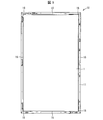
- FIG. 5 is a front view schematically showing the exterior of the electric signboard 10.
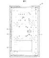
- FIG. 6 is a rear view schematically showing the exterior of the electric signboard 10.
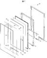
- FIG. 7 is an exploded view schematically showing the internal configuration of the electrical signboard 10.
- FIG. 8 is an exploded view schematically showing the configuration of the backlight chassis portion 30 of the electric signboard 10.
- the electric signboard 10 includes a base part (fixing part) 11, a power supply part 12, a backlight chassis part fixing bracket (holding part) 13, a backlight chassis part 30, a lens sheet (translucent plate) 14, a milky white translucent plate ( Diffusion plate) 15, milky white translucent plate fixing bracket 16, film fixing bracket (film fixing portion) 17, film corner fixing bracket (hanging portion) 18, acrylic plate (transparent lid) 19, and lid frame 20, and milky white
- the film 1 is held between the translucent plate 15 and the acrylic plate 19. 5 does not show the acrylic plate 19 and the lid frame 20, and FIG. 7 does not show the lid frame 20.
- the backlight chassis unit 30 includes a backlight chassis 31, a reflection sheet 32, an LED substrate (light source, LED light source) 33, a middle chassis 34, and a light guide plate 35.
- the base part 11 is a base part for attaching the electric signboard 10 to the wall surface.
- the backlight chassis portion fixing bracket 13 is a bracket for holding the backlight chassis portion 30 and attaching the backlight chassis portion 30 to the base portion 11, and has a shape corresponding to the backlight chassis portion 30.
- the backlight chassis portion fixing bracket 13 is screwed to the outer peripheral portion of the backlight chassis portion 30 mainly on the bottom surface (the surface on the base portion 11 side) (see FIG. 6) and is hinged to the base portion 11. And is rotatable with respect to the base portion 11 (described later).
- the backlight chassis unit 30 is configured such that light emitted from the LED substrate 33 enters the light guide plate 35 and the light emitted from the light guide plate 35 irradiates the entire surface of the milky white translucent plate 15. That is, in the backlight chassis unit 30, the light guide plate 35 is disposed on the most milky white translucent plate 15 side.
- the backlight portion of a liquid crystal television can be used as the backlight chassis unit 30.
- a BL chassis, a middle chassis, a light guide plate, a reflective sheet, an LED substrate, a heat sink, etc. in a liquid crystal television can be used as they are. However, there is no need to divert the optical sheet and the liquid crystal panel.
- the LED substrate 33 as a light source, a long life can be realized, luminance unevenness can be reduced, and luminance can be increased.
- the power supply unit (power supply board) 12 is a circuit unique to the electric signboard, and is a circuit that is supplied with commercial power via a simple switch and supplies power to the LED board 33.
- the power supply unit 12 is disposed on the base unit 11 side of the backlight chassis 31. In other words, the power supply unit 12 is fixed to the backlight chassis unit 30 and is held by the backlight chassis unit fixing bracket 13.
- a light control circuit (light control board) (not shown) is also provided.
- the dimming circuit is a circuit that detects ambient brightness, and is arranged at a position where light can be detected (for example, the backlight chassis unit 30).
- the milky white translucent plate 15 is a diffusion plate unique to an electric signboard. However, a translucent or transparent diffusion plate of milky white or other colors may be used according to the type of advertisement.
- the diffusion plate in general can be formed, for example, by dispersing light scattering fine particles in a polymer.
- the milky white translucent plate fixing bracket 16 is a bracket for fixing the milky white translucent plate 15 to the backlight chassis 31, and is provided so as to hook four sides of the milky white translucent plate 15.
- the lens sheet 14 provided with a concavo-convex structure on both sides is disposed between the light guide plate 35 and the milky white translucent plate 15.
- the film 1 is a film on which an advertisement or the like is drawn, and the illuminated signboard 10 displays the advertisement or the like when the film is irradiated with light.
- the film fixing bracket 17 is a bracket for fixing the film 1 on the milky white translucent plate 15, and is provided on the upper side of the backlight chassis portion fixing bracket 13.
- the film corner fixing bracket 18 is a bracket that hooks the four corners of the film 1 to prevent the film 1 from being turned over.
- the acrylic plate 19 is a transparent protective plate and is attached to the lid frame 20.
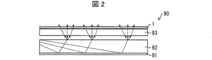
- FIG. 2 is a side cross-sectional view schematically showing the configuration of the main part of the electric signboard 90 according to the prior art.
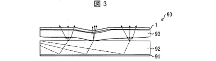
- FIG. 3 is a side cross-sectional view schematically showing a state in which the milky white translucent plate 93 is distorted in the electric signboard 90.
- the electric signboard 90 includes a reflection sheet 91, a light guide plate 92, and a milky white translucent plate 93, and a film is held on the milky white translucent plate 93.
- Light emitted from a light source (not shown) and incident from the side surface of the light guide plate 92 is emitted in the display surface direction of the light guide plate 92 (the direction from the light guide plate 92 toward the film 1, the upper direction on the paper surface).
- the light is further diffused by the milky white translucent plate 93, reaches the film 1 and illuminates an advertisement or the like drawn on the film 1.
- the milky white translucent plate 93 is distorted due to an external pressure or the like and comes into close contact with the light guide plate 92, the light emitted from the light guide plate 92 is not diffused in the air layer and is applied to the milky white translucent plate 93. Since the light is incident, the region where the light guide plate 92 and the milky white translucent plate 93 are in close contact with each other has higher luminance than the other regions, resulting in luminance unevenness (see FIG. 3).
- FIG. 1 is a side cross-sectional view schematically showing a main part configuration of the electric signboard 10.
- the lens sheet 14 has a concavo-convex structure formed on both surfaces thereof to prevent adhesion between the surfaces facing the respective surfaces. Therefore, even if the milky white translucent plate 15 is distorted, the milky white translucent plate 15 and the lens sheet 14 or the lens sheet 14 and the light guide plate 35 are not in close contact with each other. An air layer can be maintained between them (see FIG. 1). Thereby, the light emitted from the light guide plate 35 always passes through the air layer, and stable light diffusion is possible. Thereby, luminance unevenness can be suppressed.
- the translucent plate inserted between the light guide plate 35 and the milky white translucent plate 15 is not limited to the lens sheet 14, but at least Any translucent plate having a concavo-convex structure on one side may be used.
- the concavo-convex structure is more preferably a concavo-convex structure for preventing adhesion between the surface opposite to the surface provided with the concavo-convex structure.
- Such a translucent plate may be, for example, a transparent or translucent sheet that is at least one-side matte, satin or textured.
- the present invention is not limited to a configuration in which a light transmitting plate having an uneven structure such as the lens sheet 14 is disposed between the light guide plate 35 and the milky white translucent plate 15.
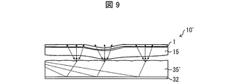
- FIG. 9 is a side cross-sectional view schematically showing a main configuration of an electric signboard 10 ′ according to the second embodiment of the present invention.
- the electrical signboard 10 ′ has a configuration in which a concavo-convex structure for preventing close contact with the milky white translucent plate 15 is provided on a surface of the light guide plate 35 ′ facing the milky white translucent plate 15. According to this configuration, even if the milky white translucent plate 15 is distorted, the milky white translucent plate 15 and the light guide plate 35 ′ do not adhere to each other, and an air layer is formed between the milky white translucent plate 15 and the light guide plate 35 ′. Can be maintained (see FIG. 9). Thereby, the light emitted from the light guide plate 35 always passes through the air layer, and stable light diffusion is possible. Thereby, even if there is no lens sheet 14, a brightness nonuniformity can be suppressed.
- FIG. 10 is a side cross-sectional view schematically showing a main part configuration of an electric signboard 10 ′′ according to the third embodiment of the present invention.
- the electric signboard 10 ′′ has a configuration in which a concavo-convex structure for preventing adhesion between the milky white translucent plate 15 ′ and the light guide plate 35 is provided on a surface facing the light guide plate 35.
- a concavo-convex structure for preventing adhesion between the milky white translucent plate 15 ′ and the light guide plate 35 is provided on a surface facing the light guide plate 35.
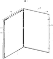
- FIG. 11 is a perspective view schematically showing a state in which the acrylic board 19 and the lid frame 20 are opened in the electric signboard 10.
- the acrylic plate 19 and the lid frame 20 are hinged to the base portion 11 and are opened by rotating counterclockwise.
- the direction of rotation is not particularly limited.
- the end of the film 1 is fixed by a film fixing bracket (film holder) 17 provided on the upper part of the backlight chassis fixing bracket 13 and is held so as to be suspended. Thereby, the film 1 can be hold
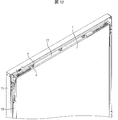
- FIG. 12 is an enlarged perspective view schematically showing the film fixing bracket 17 of the electric signboard 10.
- FIGS. 14C and 14D are views for explaining a locking mechanism of the film fixing bracket 17.
- the film fixing bracket 17 is a lock mechanism that fixes the film 1 when slid in one direction. That is, the screw x is inserted into the groove y of the film fixing bracket 17, and the groove y has a bent shape.
- a gap is generated between the milky white translucent plate 15 and the film fixing bracket 17 (see FIGS. 12 and 14 (c)). 1 is inserted, and the end of the film 1 can be fixed by sliding the film fixing bracket 17 rightward toward the paper surface (see (d) of FIG. 14).
- the film fixing bracket 17 since the film fixing bracket 17 is shifted in one direction when fixing the film 1, the film 1 may follow the movement of the film fixing bracket 17 and the position of the film 1 may shift. Further, since the film 1 is very thin, it is likely to be loosened. Therefore, it may take time to fix the film 1.
- a film fixing bracket 17 ′ including a first fixing portion 17′a that fixes a part of the film 1 and a second fixing portion 17′b that fixes the other part of the film 1 is used.
- the first fixing portion 17′a and the second fixing portion 17′b fix the film 1 when they are slid in directions away from each other.
- FIG. 13 is an enlarged perspective view schematically showing the film fixing bracket 17 ′.
- FIGS. 14A and 14B are diagrams for explaining a locking mechanism of the film fixing bracket 17 ′.
- the first fixing portion 17'a and the second fixing portion 17'b are each provided with a groove y, and a screw x is inserted in each groove y.
- Each of the grooves y has a bent shape.
- the film 1 is inserted into the gap, and the first fixing portion 17′a is slid leftward with respect to the paper surface, so that the second fixing portion
- the end of the film 1 can be fixed by sliding 17′b in the right direction toward the paper surface (see FIG. 13B and FIG. 14B).
- film 1 is fixed when 1st fixing
- fixed part 17'b are slid in the direction which mutually separates, film 1 is 1st fixing.
- the shift of the film 1 can be suppressed without following the movement of either the portion 17′a or the second fixing portion 17′b.
- the film 1 is pulled in opposite directions by the first fixing portion 17 ′ a and the second fixing portion 17 ′ b, the film 1 is more difficult to wrinkle.
- luminance unevenness due to the close contact between the milky white translucent plate 15 and the light guide plate 35 can be reduced. That is, when the film 1 is fixed at one point, a force is applied to the portion, and the milky white translucent plate 15 and the light guide plate 35 may be brought into close contact with each other, resulting in uneven brightness. However, when the film 1 is pressed and fixed on a flat surface as in this structure, the film 1 is pressed on a wider surface. Further, since the milky white translucent plate 15 and the light guide plate 35 that are close to the film 1 are pressed on a wide surface, the milky white translucent plate 15 is prevented from being distorted and closely attached to the light guide plate 35, thereby preventing uneven brightness. Can be suppressed.
- the film In a general electric signboard, the film is very thin. In addition, the lighting of the electric signboard is often set to high luminance so that advertisements and the like can be visually recognized by distant people, and the interior of the electric signboard may become hot. And if a thin film as described above is exposed to a high temperature state for a long time, it may be deformed by heat. In that case, the edge part of a film, especially four corners may float from a milky white translucent board.
- FIG. 15 is an enlarged view schematically showing the film corner fixture 18 of the electric signboard 10.
- the film corner fixing bracket 18 covers the corner of the milky white translucent plate 15 and is provided so that the film 1 can be inserted between the milky white translucent plate 15 and the film corner fixing bracket 18. Is inserted between the milky white translucent plate 15 and the film corner fixing bracket 18, the corner of the film 1 can be hooked on the film corner fixing bracket 18. Thereby, the corner of the film 1 can be prevented from floating from the milky white translucent plate 15.
- the film corner fixing bracket 18 is provided at a position corresponding to the four corners of the milky white translucent plate 15.
- the electric signboard is generally installed fixed to a wall surface. Therefore, when a failure occurs in an electrical part such as a light source, it is necessary to remove the entire sign from the wall surface, and to check and repair the failure of the electrical part, which makes maintenance work complicated.
- the backlight chassis part fixing bracket 13 is hinged to the base part 11 and the backlight chassis part 30 is simply rotated while the base part 11 is fixed to the wall surface.
- the power supply unit 12 on the back surface (base unit 11 side) of the backlight chassis unit 30 can be exposed. Thereby, the maintenance work of the power supply part 12 can be performed easily.
- FIG. 16 is a perspective view schematically showing a state in which the backlight chassis 30 of the electric signboard 10 is rotated, and (a) and (b) are diagrams in which the observation directions are changed.
- the acrylic plate 19 and the lid frame 20 are rotated counterclockwise, and then the backlight chassis unit 30 is rotated clockwise, whereby the power supply unit 12 disposed on the back surface of the backlight chassis unit 30. Can be exposed.
- the rotation direction of the backlight chassis 30 is not particularly limited and can be arbitrarily set. However, for ease of operation, the backlight chassis unit 30 is rotated in a direction opposite to the rotation direction of the acrylic plate 19 and the lid frame 20. It is preferable to be able to move. Further, the rotation range of the backlight chassis portion 30 is not particularly limited, but it is preferable that the backlight chassis portion 30 is rotated at least 90 degrees from the viewpoint of ease of maintenance.
- FIG. 17 is a perspective view schematically showing a hinge 21 for rotating the backlight chassis unit 30 of the electrical signboard 10, and FIG. 17A rotates the backlight chassis unit 30 of the electrical signboard 10.
- (B) shows the enlarged view around the hinge 21, respectively.
- the backlight chassis portion fixing bracket 13 is hinged to the base portion 11 by a hinge 21, so that the backlight chassis portion 30 can be rotated.
- FIG. 18 is a perspective view schematically showing a Dharma hole 22 for fixing the backlight chassis portion 30 of the electric signboard 10, and FIG. 18A is a diagram illustrating the backlight chassis portion 30 of the electric signboard 10.
- B shows the enlarged view around the Dharma hole 22, respectively.
- a Dalma-type hole 22 is provided on the side of the backlight chassis portion fixing bracket 13 opposite to the hinge 21, and the backlight chassis portion fixing bracket 13 is screwed to the base portion 11 through the Dalma-type hole 22.
- the backlight chassis 30 can be fixed so as not to rotate. When rotating the backlight chassis 30, the screw that passes through the Dalma hole 22 may be removed, but the bottom hole of the Dalma hole 22 is larger than the head of the screw.
- the backlight chassis part 30 can be rotated only by slightly lifting 30.
- a dimming circuit (not shown) may be disposed on the back surface of the backlight chassis unit 30. In that case, the dimming circuit is exposed by rotating the backlight chassis unit 30, and dimming is performed. Circuit maintenance can also be easily performed.
- Step of milky white translucent plate In the electric signboard, the film is arranged so as to cover the milky white translucent plate.
- the part which mounts a film is flat. This is because when a film is placed on a non-flat portion, a step is generated on the film, which causes wrinkles and distortion.
- a backlight module of a liquid crystal television is used as a light source, it is difficult to flatten a portion on which a film is placed. This is because a structure for holding the milky white translucent plate is required.
- the milky white translucent plate is pressed from the display side (the side opposite to the backlight module) with a metal fitting, the metal fitting protrudes beyond the milky white translucent plate. This is because the flatness of the portion on which the film is placed is lost.
- the outer peripheral portion 15a of the surface facing the light guide plate 35 in the milky white translucent plate 15 is recessed with respect to the inner peripheral portion 15b of the surface, and the milky white translucent plate fixing bracket 16 is provided. Is configured to press the outer peripheral portion. Thereby, the milky white translucent plate fixing metal fitting 16 can avoid protruding, and can ensure the flatness of the part which mounts a film.
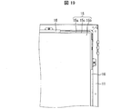
- FIG. 19 is an enlarged view schematically showing the milky white translucent plate 15 and the milky white translucent plate fixing bracket 16 of the electric signboard 10.
- FIG. 20 is a side cross-sectional view schematically showing the milky white translucent plate 15 and the milky white translucent plate fixture 16 of the electric signboard 10.
- a step 15c is provided between the outer peripheral portion 15a and the inner peripheral portion 15b of the milky white translucent plate 15 so that the outer peripheral portion 15a is recessed with respect to the inner peripheral portion 15b. It can suppress that the metal fitting 16 protrudes.
- the depth of the step 15c is more preferably the same as or deeper than the milky white translucent plate fixing bracket 16, but if the step 15c is provided even slightly, the milky white translucent plate fixing bracket 16 protrudes toward the film 1 side. Since the amount can be reduced, the effect of the invention can be obtained.
- the outer peripheral portion 15a of the milky white translucent plate 15 is recessed with respect to the inner peripheral portion 15b, so that even when the outer peripheral portion 15a is pressed by the milky white translucent plate fixing bracket 16 or the like, the milky white translucent plate is translucent. It can suppress that the flatness on the board 15 is impaired. Thereby, the film 1 can be suitably disposed on the milky white translucent plate 15.
- luminance unevenness due to the close contact between the milky white translucent plate 15 and the light guide plate 35 can be reduced. That is, when the milky white translucent plate fixing bracket 16 protrudes in the direction of the acrylic plate 19, the force from the acrylic plate 19 is applied to the milky white translucent plate fixing bracket 16 with priority. If it does so, force will be applied to that part and milky white translucent board 15 and light guide plate 35 may stick closely according to it, and it may become uneven brightness. However, if the surface on which the film 1 is placed is flat with respect to the acrylic plate 19 as in this structure, the milky white translucent plate 15 and the light guide plate 35 are in contact with the acrylic plate 19 on a wider surface. Will also hold in a wide area. Therefore, the milky white translucent plate 15 can be prevented from being distorted and brought into close contact with the light guide plate 35, and the occurrence of luminance unevenness can be suppressed.
- the light source device (10 ′, 10 ′′) includes a light source (LED substrate 33), a light guide plate (35, 35 ′), a diffusion plate (milky white translucent plate 15, 15 ′), The surface of the light guide plate facing the diffusion plate or the surface of the diffusion plate facing the light guide plate is provided with a concavo-convex structure.
- the light source device (10) includes a light source (LED substrate 33), a light guide plate (35, 35 ′), and a diffusion plate (milky white translucent plate 15, 15 ′).
- a light transmitting plate (lens sheet 14) is further provided between the light guide plate and the diffusion plate, and the uneven structure is provided on at least one surface of the light transmitting plate.
- the uneven structure provided on the light guide plate, the diffusion plate, or the translucent plate allows the air layer to exist stably between the light guide plate and the diffusion plate, thereby suppressing luminance unevenness. can do.
- the light source device according to aspect 3 of the present invention is the light source device according to aspect 1 or 2, wherein the uneven structure is a structure for preventing adhesion between a surface provided with the uneven structure and a surface facing the surface. It is preferable that
- the light guide plate and the diffusion plate, or the light guide plate and the light transmission plate, or the light transmission plate and the diffusion plate are not in close contact with each other due to the uneven structure.
- the layer can exist more stably.
- the light source device according to Aspect 4 of the present invention is the light source device according to Aspects 1 to 3, wherein the film fixing part (17, 17) suspends and fixes the film (1) so as to cover the surface facing the light guide plate of the diffusion plate. 17 ') may further be provided.
- the film can be successfully held at the position where light is irradiated.
- the light source device according to Aspect 5 of the present invention is the light source device according to Aspect 4, wherein the film fixing part is a first fixing part (17′a) that fixes a part of the film and a second part that fixes the other part of the film.
- Two fixing parts (17′b) may be provided, and the first fixing part and the second fixing part may fix the film when slid in directions away from each other.
- the light source device may further include a latching portion (film corner fixing bracket 18) for latching the four corners of the film on the diffusion plate in the aspect 4 or 5.
- a latching portion film corner fixing bracket 18 for latching the four corners of the film on the diffusion plate in the aspect 4 or 5.
- the light source device is the power source unit (12) for supplying power to the light source, and the holding unit (backlight) for holding the power source unit, the light source, and the light guide plate.
- the holding portion is hinged to the fixing portion and rotates the holding portion. As a result, the power supply unit may be exposed.
- the light source device according to aspect 8 of the present invention is the light source device according to aspects 1 to 7, in which the outer peripheral portion (15a) of the surface facing the light guide plate of the diffuser plate is opposite to the inner peripheral portion (15b) of the surface. It may be recessed.
- the light source device may further include a transparent lid (acrylic plate 19) for pairing with the diffusion plate and sandwiching the film in the above aspects 1 to 8.
- a transparent lid (acrylic plate 19) for pairing with the diffusion plate and sandwiching the film in the above aspects 1 to 8.
- the film can be successfully protected.
- the light source may be an LED light source.
- the diffusion plate may be a milky white translucent plate.
- the electric signboard according to the twelfth aspect of the present invention includes the light source device according to any one of the first to eleventh aspects.
- the present invention can be used in the field of manufacturing a light source device.
Landscapes
- Physics & Mathematics (AREA)
- General Physics & Mathematics (AREA)
- Engineering & Computer Science (AREA)
- Theoretical Computer Science (AREA)
- Planar Illumination Modules (AREA)
- Illuminated Signs And Luminous Advertising (AREA)
- Light Guides In General And Applications Therefor (AREA)
Abstract
電飾看板(10)では、導光板(35)における乳白色半透明板(15)に対向する面、若しくは、乳白色半透明板(15)における導光板(35)に対向する面に凹凸構造が設けられているか、又は、導光板(35)および乳白色半透明板(15)の間に、少なくとも片面に凹凸構造が設けられているレンズシート(14)をさらに備えている。これにより、光源、導光板および拡散板を備えた光源装置において、輝度ムラを抑制する。
Description
本発明は、光源装置および電飾看板に関するものである。
ボックス内に光源を配置し、表示に広告等のフィルムを配置して夜間でも宣伝できるようにした電飾看板(コルトン看板とも称される)が知られている。例えば、特許文献1には、透明乃至半透明の基材と、該基材の裏面に積層した透明乃至半透明の粘着剤層と、上記基材の表面に形成した印刷インクによる表示部と、から成る印刷シート体を、上記粘着剤層を介して透明乃至半透明のプラスチック板に貼り付け、光源から光線を照射して、上記表示部を電飾表示する電飾看板が記載されている。
近年、このような電飾看板の光源として、液晶テレビのバックライトと同様の構成を採用することが検討されている(例えば、特許文献2)。その場合、なるべく電飾看板の厚みを薄くするために、液晶テレビのバックライトモジュールにおける光源および導光板(LGP)のみを流用し、光学シートは省く場合が多い。
本発明者らは、光源、導光板および拡散板を備えた光源装置について鋭意検討している。
ここで、通常、導光板と拡散板との間には非常に薄い空気層が存在する。しかし、拡散板の歪み等に起因して導光板と拡散板とが密着すると、この空気層が無くなるため、拡散板における反射量が変化し、密着部分の輝度が増加する。結果、光源とは反対側から見たときに、斑点状の輝度ムラが生じる。
本発明は、上記課題に鑑みてなされたものであり、光源、導光板および拡散板を備えた光源装置において、輝度ムラを抑制するための技術を提供することを主たる目的とする。
上記の課題を解決するために、本発明の一態様に係る光源装置は、光源と、導光板と、拡散板と、を備え、該導光板における該拡散板に対向する面、若しくは、該拡散板における該導光板に対向する面に凹凸構造が設けられている、ことを特徴としている。
また、本発明の他の態様に係る光源装置は、光源と、導光板と、拡散板と、を備え、該導光板および該拡散板の間に、透光板をさらに備え、該透光板の少なくとも片面に、該凹凸構造が設けられている、ことを特徴としている。
本発明の一態様によれば、導光板、拡散板または透光板に設けられた凹凸構造によって、導光板と拡散板との間に空気層を安定して存在せしめることができるので、輝度ムラを抑制することができる。
(電飾看板の概略構成)
以下、本発明の実施形態について、図面を参照して詳細に説明する。以下では、本発明に係る光源装置の構成例として、全体が四角形の縦型60インチサイズの電飾看板について説明するが、本発明はこれに限定されず、光源、導光板および拡散板を備える光源装置一般に適用することができ、サイズ、形状についても様々なものを用いることができる。また、説明の便宜上、各実施形態において、他の実施形態にて説明した部材と同じ機能を有する部材については、同じ符号を付記し、その説明を省略する。
以下、本発明の実施形態について、図面を参照して詳細に説明する。以下では、本発明に係る光源装置の構成例として、全体が四角形の縦型60インチサイズの電飾看板について説明するが、本発明はこれに限定されず、光源、導光板および拡散板を備える光源装置一般に適用することができ、サイズ、形状についても様々なものを用いることができる。また、説明の便宜上、各実施形態において、他の実施形態にて説明した部材と同じ機能を有する部材については、同じ符号を付記し、その説明を省略する。
(第1の実施形態)
図4は、第1の実施形態に係る電飾看板(光源装置)10の外観を模式的に示す斜視図である。図5は、電飾看板10の外観を模式的に示す正面図である。図6は、電飾看板10の外観を模式的に示す背面図である。図7は、電飾看板10の内部構成を模式的に示す分解図である。図8は、電飾看板10のバックライトシャーシ部30の構成を模式的に示す分解図である。
図4は、第1の実施形態に係る電飾看板(光源装置)10の外観を模式的に示す斜視図である。図5は、電飾看板10の外観を模式的に示す正面図である。図6は、電飾看板10の外観を模式的に示す背面図である。図7は、電飾看板10の内部構成を模式的に示す分解図である。図8は、電飾看板10のバックライトシャーシ部30の構成を模式的に示す分解図である。
電飾看板10は、ベース部(固定部)11、電源部12、バックライトシャーシ部固定金具(保持部)13、バックライトシャーシ部30、レンズシート(透光板)14、乳白色半透明板(拡散板)15、乳白色半透明板固定金具16、フィルム固定金具(フィルム固定部)17、フィルムコーナー固定金具(掛止部)18、アクリル板(透明蓋)19、および蓋枠20を備え、乳白色半透明板15とアクリル板19との間にフィルム1を保持している。なお、図5では、アクリル板19および蓋枠20を示しておらず、図7では、蓋枠20を示していない。
バックライトシャーシ部30は、バックライトシャーシ31、反射シート32、LED基板(光源、LED光源)33、ミドルシャーシ34および導光板35を備えている。
ベース部11は、電飾看板10を壁面に取り付けるための土台部分である。バックライトシャーシ部固定金具13は、バックライトシャーシ部30を保持し、バックライトシャーシ部30をベース部11に取り付けるための金具であり、バックライトシャーシ部30に応じた形状を有している。バックライトシャーシ部固定金具13は、バックライトシャーシ部30の主として底面(ベース部11側の面)の外周部分とビス止めされるとともに(図6参照)、ベース部11に対して蝶着されており、ベース部11に対して回動可能になっている(後述)。
バックライトシャーシ部30は、LED基板33が出射した光が導光板35に入射し、導光板35から出射された光が、乳白色半透明板15全面を照射するように構成されている。すなわち、バックライトシャーシ部30では、導光板35が、最も乳白色半透明板15側に配置されている。バックライトシャーシ部30は、例えば、液晶テレビのバックライト部分を流用することができる。詳細には、液晶テレビにおけるBLシャーシ、ミドルシャーシ、導光板、反射シート、LED基板、放熱板等をそのまま使用することができる。但し、光学シートおよび液晶パネルについては流用の必要がない。なお、光源としてLED基板33を用いることにより、長寿命を実現し、輝度ムラを小さくし、輝度を大きくすることができる。
電源部(電源基板)12は、電飾看板特有の回路であり、簡単なスイッチを介して商用電源が供給されており、LED基板33に電力を供給する回路である。電源部12は、バックライトシャーシ31のベース部11側に配設されている。言い換えれば、電源部12は、バックライトシャーシ部30に固定されており、バックライトシャーシ部固定金具13によって保持されている。
また、図示しない調光回路(調光基板)も配設されている。調光回路は、周囲の明るさを検出する回路であり、光の検出が可能な位置(例えば、バックライトシャーシ部30)に配置されている。
乳白色半透明板15は、電飾看板特有の拡散板である。但し、広告の種類に応じて、乳白色または他の色の半透明または透明の拡散板を用いてもよい。拡散板一般は、例えば、光散乱微粒子をポリマー中に分散させることにより形成することができる。また、乳白色半透明板固定金具16は、乳白色半透明板15をバックライトシャーシ31に固定する金具であり、乳白色半透明板15の四辺を掛止するように設けられている。
また、両面に凹凸構造が設けられたレンズシート14が、導光板35と乳白色半透明板15との間に配置されている。
フィルム1は、広告等が描画されたフィルムであり、これに光が照射されることによって、電飾看板10は広告等を表示する。フィルム固定金具17は、フィルム1を乳白色半透明板15上に固定する金具であり、バックライトシャーシ部固定金具13の上辺に設けられている。フィルムコーナー固定金具18は、フィルム1の四隅を掛止して、フィルム1のめくれを防止する金具である。
アクリル板19は、透明の保護板であり、蓋枠20に取り付けられている。
(レンズシートの効果)
ここで、レンズシート14を設けたことの効果について説明する。まず、レンズシート14が存在しない従来技術について図2および図3を参照して説明する。図2は、従来技術に係る電飾看板90の要部構成を模式的に示す側方断面図である。図3は、電飾看板90において、乳白色半透明板93に歪みが生じた状態を模式的に示す側方断面図である。
ここで、レンズシート14を設けたことの効果について説明する。まず、レンズシート14が存在しない従来技術について図2および図3を参照して説明する。図2は、従来技術に係る電飾看板90の要部構成を模式的に示す側方断面図である。図3は、電飾看板90において、乳白色半透明板93に歪みが生じた状態を模式的に示す側方断面図である。
電飾看板90は、反射シート91、導光板92および乳白色半透明板93を備え、乳白色半透明板93上にフィルムが保持されている。図示しない光源から出射され、導光板92の側面から入射した光は、導光板92の表示面方向(導光板92からフィルム1に向かう方向、紙面上方向)に放射される。光は、乳白色半透明板93によってさらに拡散され、フィルム1に到達し、フィルム1に描画された広告等を照らす。また、導光板92と乳白色半透明板93との間には、薄い空気層が存在し、導光板92から出射された光は、一旦当該空気層において拡散し、その後、乳白色半透明板93に入射する(図2参照)。
しかし、乳白色半透明板93が、外圧等に起因して歪み、導光板92と密着してしまうと、導光板92から出射された光は、空気層で拡散することなく乳白色半透明板93に入射されるため、導光板92と乳白色半透明板93とが密着している領域は、その他の領域よりも輝度が増加し、輝度ムラが生じる(図3参照)。
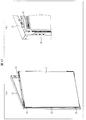
これに対し、本実施形態に係る電飾看板10では、導光板35と乳白色半透明板15との間にレンズシート14を配置することにより、以下のように輝度ムラを抑制することができる。図1は、電飾看板10の要部構成を模式的に示す側方断面図である。レンズシート14はその両面に、それぞれの面に対向する面との間の密着を防止するための凹凸構造が形成されている。そのため、乳白色半透明板15が歪んだとしても、乳白色半透明板15とレンズシート14、又は、レンズシート14と導光板35が密着することがなく、乳白色半透明板15と導光板35との間に空気層を維持することができる(図1参照)。これにより、導光板35から出射された光は、必ず空気層を通るようになり、安定した光拡散が可能となる。これにより、輝度ムラを抑制することができる。
なお、導光板35と乳白色半透明板15との間に空気層を維持できる限り、導光板35と乳白色半透明板15との間に挿入する透光板はレンズシート14に限定されず、少なくとも片面に凹凸構造が設けられた透光板であればよい。さらに、凹凸構造は、当該凹凸構造が設けられた面に対向する面との間の密着を防止するための凹凸構造であればより好ましい。そのような透光板としては、例えば、少なくとも片面マット地、梨地またはシボ加工されている透明または半透明のシートであり得る。
なお、本発明は、導光板35と乳白色半透明板15との間に、レンズシート14のような凹凸構造を有する透光板を配置する構成に限定されない。
(第2の実施形態)
図9は、本発明の第2の実施形態に係る電飾看板10’の要部構成を模式的に示す側方断面図である。電飾看板10’では、導光板35’における乳白色半透明板15に対向する面に、乳白色半透明板15との間の密着を防止するための凹凸構造が設けられている構成である。当該構成によれば、乳白色半透明板15が歪んだとしても、乳白色半透明板15と導光板35’が密着することがなく、乳白色半透明板15と導光板35’との間に空気層を維持することができる(図9参照)。これにより、導光板35から出射された光は、必ず空気層を通るようになり、安定した光拡散が可能となる。これにより、レンズシート14が無くとも、輝度ムラを抑制することができる。
図9は、本発明の第2の実施形態に係る電飾看板10’の要部構成を模式的に示す側方断面図である。電飾看板10’では、導光板35’における乳白色半透明板15に対向する面に、乳白色半透明板15との間の密着を防止するための凹凸構造が設けられている構成である。当該構成によれば、乳白色半透明板15が歪んだとしても、乳白色半透明板15と導光板35’が密着することがなく、乳白色半透明板15と導光板35’との間に空気層を維持することができる(図9参照)。これにより、導光板35から出射された光は、必ず空気層を通るようになり、安定した光拡散が可能となる。これにより、レンズシート14が無くとも、輝度ムラを抑制することができる。
(第3の実施形態)
図10は、本発明の第3の実施形態に係る電飾看板10’’の要部構成を模式的に示す側方断面図である。電飾看板10’’では、乳白色半透明板15’における導光板35に対向する面に、導光板35との間の密着を防止するための凹凸構造が設けられている構成である。当該構成によれば、乳白色半透明板15’が歪んだとしても、乳白色半透明板15’と導光板35が密着することがなく、乳白色半透明板15’と導光板35との間に空気層を維持することができる(図10参照)。これにより、導光板35から出射された光は、必ず空気層を通るようになり、安定した光拡散が可能となる。これにより、レンズシート14が無くとも、輝度ムラを抑制することができる。
図10は、本発明の第3の実施形態に係る電飾看板10’’の要部構成を模式的に示す側方断面図である。電飾看板10’’では、乳白色半透明板15’における導光板35に対向する面に、導光板35との間の密着を防止するための凹凸構造が設けられている構成である。当該構成によれば、乳白色半透明板15’が歪んだとしても、乳白色半透明板15’と導光板35が密着することがなく、乳白色半透明板15’と導光板35との間に空気層を維持することができる(図10参照)。これにより、導光板35から出射された光は、必ず空気層を通るようになり、安定した光拡散が可能となる。これにより、レンズシート14が無くとも、輝度ムラを抑制することができる。
なお、電飾看板10’および10’’における、レンズシート14および凹凸構造以外の構成は、電飾看板10と同様である。
(フィルム固定部)
一般的に、電飾看板において、広告等が描画されたフィルムは頻繁に交換される。そこで、本実施形態では、アクリル板19および蓋枠20を容易に開けるようにして、乳白色半透明板15上に吊り下げられたフィルム1を容易に交換可能にしている。
一般的に、電飾看板において、広告等が描画されたフィルムは頻繁に交換される。そこで、本実施形態では、アクリル板19および蓋枠20を容易に開けるようにして、乳白色半透明板15上に吊り下げられたフィルム1を容易に交換可能にしている。
図11は、電飾看板10において、アクリル板19および蓋枠20を開いた状態を模式的に示す斜視図である。アクリル板19および蓋枠20は、ベース部11に対して蝶着されており、反時計回りに回動することによって開くようになっている。なお、回動の方向は特に限定されない。フィルム1は、バックライトシャーシ部固定金具13の上部に設けられたフィルム固定金具(フィルムホルダー)17によって端部が固定されており、吊り下げられるように保持されている。これにより、光が照射される位置にフィルム1を首尾よく保持することができる。
図12は、電飾看板10のフィルム固定金具17を模式的に示す拡大斜視図である。また、図14の(c)および(d)は、フィルム固定金具17のロック機構を説明する図である。フィルム固定金具17は、一方向にスライドさせたときにフィルム1を固定するロック機構である。すなわち、フィルム固定金具17の溝yにネジxが挿入されており、溝yは折れ曲がった形状をしている。フィルム固定金具17を紙面向かって左方向にスライドさせると、乳白色半透明板15とフィルム固定金具17との間に隙間が生じるので(図12、図14の(c)参照)、当該隙間にフィルム1を挿入し、フィルム固定金具17を紙面向かって右方向にスライドさせることで、フィルム1の端部を固定することができる(図14の(d)参照)。
但し、フィルム固定金具17は、フィルム1を固定する際に、一方向にずらしていくため、フィルム1がフィルム固定金具17の動きに追従してフィルム1の位置がずれてしまう場合がある。また、フィルム1は、非常に薄いものであるため、弛み等が発生し易く、ゆえにフィルム1の固定に手間取る場合がある。
(第4の実施形態)
そこで、第4の実施形態では、フィルム1の一部分を固定する第一固定部17’aおよびフィルム1の他の部分を固定する第二固定部17’bからなるフィルム固定金具17’を用い、第一固定部17’aおよび第二固定部17’bは、互いに離反する方向にスライドさせたときにフィルム1を固定するようにしている。
そこで、第4の実施形態では、フィルム1の一部分を固定する第一固定部17’aおよびフィルム1の他の部分を固定する第二固定部17’bからなるフィルム固定金具17’を用い、第一固定部17’aおよび第二固定部17’bは、互いに離反する方向にスライドさせたときにフィルム1を固定するようにしている。
図13は、フィルム固定金具17’を模式的に示す拡大斜視図である。また、図14の(a)および(b)は、フィルム固定金具17’のロック機構を説明する図である。第一固定部17’aおよび第二固定部17’bは、それぞれ溝yを備えており、溝yにはそれぞれネジxが挿入されている。溝yはそれぞれ折れ曲がった形状をしている。第一固定部17’aを紙面向かって右方向にスライドさせ、第二固定部17’bを紙面向かって左方向にスライドさせると、乳白色半透明板15とフィルム固定金具17との間に隙間が生じるので(図13の(a)、図14の(a)参照)、当該隙間にフィルム1を挿入し、第一固定部17’aを紙面向かって左方向にスライドさせ、第二固定部17’bを紙面向かって右方向にスライドさせることで、フィルム1の端部を固定することができる(図13の(b)、図14の(b)参照)。
このように、第一固定部17’aおよび第二固定部17’bが、互いに離反する方向にスライドさせたときにフィルム1を固定するようになっているため、フィルム1が、第一固定部17’aおよび第二固定部17’bの何れか一方の動きに追従することもなく、フィルム1のずれを抑制することができる。また、フィルム1は、第一固定部17’aおよび第二固定部17’bにより、それぞれ反対方向に引っ張られるため、フィルム1にしわがより難くなる。
また、本構造によって、乳白色半透明板15と導光板35との密着による輝度ムラを軽減することができる。すなわち、フィルム1を固定する際、一点で固定してしまうと、その部分に力が掛かり、それに応じて乳白色半透明板15と導光板35とが密着して、輝度ムラとなることがある。しかし、本構造のように、フラットな面でフィルム1を圧着して固定すると、より広い面でフィルム1を押さえることになる。さらに、フィルム1に近接した乳白色半透明板15と導光板35とについても広い面で押さえることになるので、乳白色半透明板15が歪んで導光板35と密着してしまうことを避け、輝度ムラの発生を抑えることができる。
(フィルムコーナー固定金具)
一般的な電飾看板において、フィルムは、非常に薄いものである。また、電飾看板の照明は、遠くの人にも広告等が視認し得るように、高輝度に設定することが多く、電飾看板の内部は高温になる場合がある。そして、上述したような薄いフィルムが、高温状態に長時間曝されると、熱により変形することがある。その際、フィルムの端部、特に四隅が乳白色半透明板から浮いてしまうことがある。
一般的な電飾看板において、フィルムは、非常に薄いものである。また、電飾看板の照明は、遠くの人にも広告等が視認し得るように、高輝度に設定することが多く、電飾看板の内部は高温になる場合がある。そして、上述したような薄いフィルムが、高温状態に長時間曝されると、熱により変形することがある。その際、フィルムの端部、特に四隅が乳白色半透明板から浮いてしまうことがある。
(第5の実施形態)
そこで、第5の実施形態では、フィルム1の四隅が、乳白色半透明板15から浮くことを防止するために、乳白色半透明板15の四隅部分に、フィルム1の四隅を引っ掛けるためのフィルムコーナー固定金具18を設けている。図15は、電飾看板10のフィルムコーナー固定金具18を模式的に示す拡大図である。フィルムコーナー固定金具18は、乳白色半透明板15の隅部を覆うとともに、乳白色半透明板15とフィルムコーナー固定金具18との間に、フィルム1を挿入可能なように設けられており、フィルム1の隅部を乳白色半透明板15とフィルムコーナー固定金具18との間に挿入することにより、フィルム1の隅部を、フィルムコーナー固定金具18に掛止することができる。これにより、フィルム1の隅部が、乳白色半透明板15から浮くことを防止することができる。
そこで、第5の実施形態では、フィルム1の四隅が、乳白色半透明板15から浮くことを防止するために、乳白色半透明板15の四隅部分に、フィルム1の四隅を引っ掛けるためのフィルムコーナー固定金具18を設けている。図15は、電飾看板10のフィルムコーナー固定金具18を模式的に示す拡大図である。フィルムコーナー固定金具18は、乳白色半透明板15の隅部を覆うとともに、乳白色半透明板15とフィルムコーナー固定金具18との間に、フィルム1を挿入可能なように設けられており、フィルム1の隅部を乳白色半透明板15とフィルムコーナー固定金具18との間に挿入することにより、フィルム1の隅部を、フィルムコーナー固定金具18に掛止することができる。これにより、フィルム1の隅部が、乳白色半透明板15から浮くことを防止することができる。
なお、図5に示すように、フィルムコーナー固定金具18は、乳白色半透明板15の四隅に対応する位置に設けられている。
(開き構造)
電飾看板は、一般的に、壁面に固定されて設置される。そのため、光源等の電気部分に故障が生じた場合には、看板全体を壁面から取り外して、電気部分の故障の確認および修理を行う必要があり、メンテナンス作業が煩雑である。
電飾看板は、一般的に、壁面に固定されて設置される。そのため、光源等の電気部分に故障が生じた場合には、看板全体を壁面から取り外して、電気部分の故障の確認および修理を行う必要があり、メンテナンス作業が煩雑である。
(第6の実施形態)
そこで、第6の実施形態では、ベース部11に対してバックライトシャーシ部固定金具13を蝶着し、ベース部11を壁面に固定したままで、バックライトシャーシ部30を回動させるだけで、バックライトシャーシ部30の裏面(ベース部11側)の電源部12を露出させることができる。これにより、電源部12のメンテナンス作業を容易に行うことができる。
そこで、第6の実施形態では、ベース部11に対してバックライトシャーシ部固定金具13を蝶着し、ベース部11を壁面に固定したままで、バックライトシャーシ部30を回動させるだけで、バックライトシャーシ部30の裏面(ベース部11側)の電源部12を露出させることができる。これにより、電源部12のメンテナンス作業を容易に行うことができる。
図16は、電飾看板10のバックライトシャーシ部30を回動させた状態を模式的に示す斜視図であり、(a)および(b)は、それぞれ観察方向を変えた図である。まず、アクリル板19および蓋枠20を反時計回りに回動させ、次に、バックライトシャーシ部30を時計回りに回動させることにより、バックライトシャーシ部30の裏面に配置された電源部12を露出させることができる。なお、バックライトシャーシ部30の回動方向は特に限定されず、任意に設定することができるが、操作の容易性から、アクリル板19および蓋枠20の回動方向とは逆の方向に回動するようになっていることが好ましい。また、バックライトシャーシ部30の回動範囲は特に限定されないが、メンテナンスの容易性から、少なくとも90度回動するようになっていることが好ましい。
図17は、電飾看板10のバックライトシャーシ部30を回動させるための蝶番21を模式的に示す斜視図であり、(a)は、電飾看板10のバックライトシャーシ部30を回動させた状態を、(b)は、蝶番21周辺の拡大図をそれぞれ示す。ベース部11に対してバックライトシャーシ部固定金具13は蝶番21によって蝶着されており、これにより、バックライトシャーシ部30が回動可能になっている。
図18は、電飾看板10のバックライトシャーシ部30を固定するためのダルマ型穴22を模式的に示す斜視図であり、(a)は、電飾看板10のバックライトシャーシ部30を回動させた状態を、(b)は、ダルマ型穴22周辺の拡大図をそれぞれ示す。バックライトシャーシ部固定金具13における蝶番21とは反対側の辺にダルマ型穴22が設けられており、バックライトシャーシ部固定金具13を、ダルマ型穴22を通してベース部11にビス留めすることにより、バックライトシャーシ部30を回動しないように固定することができる。バックライトシャーシ部30を回動させるときは、ダルマ型穴22を通るビスを外してもよいが、ダルマ型穴22は下部の穴がビスの頭よりも大きくなっているため、バックライトシャーシ部30を若干持ち上げるだけで、バックライトシャーシ部30を回動させることができる。
なお、バックライトシャーシ部30の裏面には、図示しない調光回路が配置されていてもよく、その場合、バックライトシャーシ部30を回動させることによって、当該調光回路を露出させ、調光回路のメンテナンスも容易に行うことができる。
(乳白色半透明板の段差)
電飾看板では、フィルムは、乳白色半透明板に被せるように配置される。ここで、フィルムは、非常に薄いものであるため、フィルムを載せる部分は、フラットであることが好ましい。なぜなら、フラットでない部分にフィルムを載せた場合、フィルムに段差が生じ、しわ、歪みの原因となるからである。しかしながら、特に、光源に液晶テレビのバックライトモジュールを流用した場合、フィルムを載せる部分を、フラットにすることは困難である。なぜなら、乳白色半透明板を保持するための構造が必要であり、乳白色半透明板を金具によって表示側(バックライトモジュールとは反対側)から押さえた場合、この金具が乳白色半透明板よりも出っ張り、フィルムを載せる部分のフラット性が失われるためである。
電飾看板では、フィルムは、乳白色半透明板に被せるように配置される。ここで、フィルムは、非常に薄いものであるため、フィルムを載せる部分は、フラットであることが好ましい。なぜなら、フラットでない部分にフィルムを載せた場合、フィルムに段差が生じ、しわ、歪みの原因となるからである。しかしながら、特に、光源に液晶テレビのバックライトモジュールを流用した場合、フィルムを載せる部分を、フラットにすることは困難である。なぜなら、乳白色半透明板を保持するための構造が必要であり、乳白色半透明板を金具によって表示側(バックライトモジュールとは反対側)から押さえた場合、この金具が乳白色半透明板よりも出っ張り、フィルムを載せる部分のフラット性が失われるためである。
(第7の実施形態)
そこで、第7の実施形態では、乳白色半透明板15における導光板35に背向する面の外周部15aは、当該面の内周部15bに対して凹んでおり、乳白色半透明板固定金具16は、当該外周部を押えるようになっている。これにより、乳白色半透明板固定金具16が、突出することを避け、フィルムを載せる部分のフラット性を確保することができる。
そこで、第7の実施形態では、乳白色半透明板15における導光板35に背向する面の外周部15aは、当該面の内周部15bに対して凹んでおり、乳白色半透明板固定金具16は、当該外周部を押えるようになっている。これにより、乳白色半透明板固定金具16が、突出することを避け、フィルムを載せる部分のフラット性を確保することができる。
図19は、電飾看板10の乳白色半透明板15および乳白色半透明板固定金具16を模式的に示す拡大図である。図20は、電飾看板10の乳白色半透明板15および乳白色半透明板固定金具16を模式的に示す側方断面図である。乳白色半透明板15の外周部15aと内周部15bとの間には、内周部15bに対して外周部15aが凹むように段差15cが設けられており、これにより、乳白色半透明板固定金具16が突出することを抑制することができる。段差15cの深さは、乳白色半透明板固定金具16と同じかより深いことがより好ましいが、少しでも段差15cが設けられていれば、乳白色半透明板固定金具16のフィルム1側への突出量を低減することができるため、発明の効果が得られる。
以上のように、乳白色半透明板15の外周部15aを内周部15bに対して凹ませておくことにより、外周部15aを乳白色半透明板固定金具16等で押えた場合でも、乳白色半透明板15上のフラット性が損なわれることを抑制することができる。これにより、乳白色半透明板15上にフィルム1を好適に配置することができる。
また、本構造によって、乳白色半透明板15と導光板35との密着による輝度ムラを軽減することができる。すなわち、乳白色半透明板固定金具16がアクリル板19方向に突出していると、アクリル板19からの力が乳白色半透明板固定金具16に重点的に掛かってしまう。そうすると、その部分に力が掛かり、それに応じて乳白色半透明板15と導光板35とが密着して、輝度ムラとなることがある。しかし、本構造のように、フィルム1を載せる面が、アクリル板19に対してフラットな面であれば、より広い面でアクリル板19と接触するので乳白色半透明板15と導光板35とについても広い面で押さえることになる。よって、乳白色半透明板15が歪んで導光板35と密着してしまうことを避け、輝度ムラの発生を抑えることができる。
〔まとめ〕
本発明の態様1に係る光源装置(10’、10’’)は、光源(LED基板33)と、導光板(35、35’)と、拡散板(乳白色半透明板15、15’)と、を備え、該導光板における該拡散板に対向する面、若しくは、該拡散板における該導光板に対向する面に凹凸構造が設けられている。
本発明の態様1に係る光源装置(10’、10’’)は、光源(LED基板33)と、導光板(35、35’)と、拡散板(乳白色半透明板15、15’)と、を備え、該導光板における該拡散板に対向する面、若しくは、該拡散板における該導光板に対向する面に凹凸構造が設けられている。
また、本発明の態様2に係る光源装置(10)は、光源(LED基板33)と、導光板(35、35’)と、拡散板(乳白色半透明板15、15’)と、を備え、該導光板および該拡散板の間に、透光板(レンズシート14)をさらに備え、該透光板の少なくとも片面に、該凹凸構造が設けられている。
上記の構成によれば、導光板、拡散板または透光板に設けられた凹凸構造によって、導光板と拡散板との間に空気層を安定して存在せしめることができるので、輝度ムラを抑制することができる。
本発明の態様3に係る光源装置は、上記態様1または2において、上記凹凸構造は、当該凹凸構造が設けられた面と、当該面に対向する面との間の密着を防止するための構造であることが好ましい。
上記の構成によれば、上記凹凸構造によって、導光板と拡散板、または、導光板と透光板、もしくは、透光板と拡散板が密着しないため、導光板と拡散板との間に空気層をより安定して存在せしめることができる。
本発明の態様4に係る光源装置は、上記態様1~3において、上記拡散板における上記導光板に背向する面に被さるようにフィルム(1)を吊り下げて固定するフィルム固定部(17、17’)をさらに備えているものであってもよい。
上記の構成によれば、光が照射される位置にフィルムを首尾よく保持することができる。
本発明の態様5に係る光源装置は、上記態様4において、上記フィルム固定部は、上記フィルムの一部分を固定する第一固定部(17’a)と、上記フィルムの他の部分を固定する第二固定部(17’b)を備え、第一固定部および第二固定部は、互いに離反する方向にスライドさせたときに上記フィルムを固定するようになっていてもよい。
上記の構成によれば、フィルム固定部にフィルムを固定する際に、フィルム固定部の動きにフィルムが追従してフィルムの位置がずれることを抑制することができる。また、フィルムを互いに反対方向に引っ張ることで、フィルムにしわがよることを抑制することができる。
本発明の態様6に係る光源装置は、上記態様4または5において、上記フィルムの四隅を上記拡散板上に掛止する掛止部(フィルムコーナー固定金具18)をさらに備えていてもよい。
上記の構成によれば、フィルムの四隅におけるめくれを防止することができる。
本発明の態様7に係る光源装置は、上記態様1~6において、上記光源に電源を供給する電源部(12)と、該電源部、上記光源および上記導光板を保持する保持部(バックライトシャーシ部固定金具13)と、上記光源装置を壁面に固定する固定部(ベース部11)と、を備え、該保持部が、該固定部に蝶着されており、該保持部を回動させることによって該電源部が露出するようになっているものであってもよい。
上記の構成によれば、固定部を壁面に固定したままで、電源部を露出させることができるため、電源部のメンテナンスを容易に行うことができる。
本発明の態様8に係る光源装置は、上記態様1~7において、上記拡散板における上記導光板に背向する面の外周部(15a)は、当該面の内周部(15b)に対して凹んでいてもよい。
上記の構成によれば、拡散板の外周部を内周部に対して凹ませておくことにより、外周部を金具等で押えた場合でも、拡散板上のフラット性が損なわれることを抑制することができる。これにより、拡散板上にフィルムを好適に配置することができる。
本発明の態様9に係る光源装置は、上記態様1~8において、上記拡散板と対になってフィルムを挟むための透明蓋(アクリル板19)をさらに備えていてもよい。
上記の構成によれば、フィルムを首尾よく保護することができる。
本発明の態様10に係る光源装置は、上記態様1~9において、上記光源はLED光源であってもよい。
上記の構成によれば、長寿命を実現し、輝度ムラを小さくし、輝度を大きくすることができる。
本発明の態様11に係る光源装置は、上記態様1~10において、上記拡散板は、乳白色半透明板であってもよい。
本発明の態様12に係る電飾看板は、上記態様1~11の何れかの光源装置を具えている。
本発明は上述した各実施形態に限定されるものではなく、請求項に示した範囲で種々の変更が可能であり、異なる実施形態にそれぞれ開示された技術的手段を適宜組み合わせて得られる実施形態についても本発明の技術的範囲に含まれる。さらに、各実施形態にそれぞれ開示された技術的手段を組み合わせることにより、新しい技術的特徴を形成することができる。
本発明は、光源装置の製造分野において利用可能である。
1 フィルム
10、10’、10’’ 電飾看板(光源装置)
11 ベース部(固定部)
12 電源部
13 バックライトシャーシ部固定金具(保持部)
14 レンズシート(透光板)
15、15’ 乳白色半透明板(拡散板)
16 乳白色半透明板固定金具
17、17’ フィルム固定金具(フィルム固定部)
17’a 第一固定部
17’b 第二固定部
18 フィルムコーナー固定金具(掛止部)
19 アクリル板(透明蓋)
20 蓋枠
21 蝶番
22 ダルマ型穴
30 バックライトシャーシ部
31 バックライトシャーシ
32 反射シート
33 LED基板(光源、LED光源)
34 ミドルシャーシ
35、35’ 導光板
10、10’、10’’ 電飾看板(光源装置)
11 ベース部(固定部)
12 電源部
13 バックライトシャーシ部固定金具(保持部)
14 レンズシート(透光板)
15、15’ 乳白色半透明板(拡散板)
16 乳白色半透明板固定金具
17、17’ フィルム固定金具(フィルム固定部)
17’a 第一固定部
17’b 第二固定部
18 フィルムコーナー固定金具(掛止部)
19 アクリル板(透明蓋)
20 蓋枠
21 蝶番
22 ダルマ型穴
30 バックライトシャーシ部
31 バックライトシャーシ
32 反射シート
33 LED基板(光源、LED光源)
34 ミドルシャーシ
35、35’ 導光板
Claims (12)
- 光源と、導光板と、拡散板と、を備え、
該導光板における該拡散板に対向する面、若しくは、該拡散板における該導光板に対向する面に凹凸構造が設けられている、
ことを特徴とする光源装置。 - 光源と、導光板と、拡散板と、を備え、
該導光板および該拡散板の間に、透光板をさらに備え、該透光板の少なくとも片面に、凹凸構造が設けられている、
ことを特徴とする光源装置。 - 上記凹凸構造は、当該凹凸構造が設けられた面と、当該面に対向する面との間の密着を防止するための構造であることを特徴とする請求項1または2に記載の光源装置。
- 上記拡散板における上記導光板に背向する面に被さるようにフィルムを吊り下げて固定するフィルム固定部をさらに備えていることを特徴とする請求項1~3の何れか一項に記載の光源装置。
- 上記フィルム固定部は、上記フィルムの一部分を固定する第一固定部と、上記フィルムの他の部分を固定する第二固定部を備え、
第一固定部および第二固定部は、互いに離反する方向にスライドさせたときに上記フィルムを固定するようになっていることを特徴とする請求項4に記載の光源装置。 - 上記フィルムの四隅を上記拡散板上に掛止する掛止部をさらに備えていることを特徴とする請求項4または5に記載の光源装置。
- 上記光源に電源を供給する電源部と、
該電源部、上記光源および上記導光板を保持する保持部と、
上記光源装置を壁面に固定する固定部と、を備え、
該保持部が、該固定部に蝶着されており、該保持部を回動させることによって該電源部が露出するようになっていることを特徴とする請求項1~6の何れか一項に記載の光源装置。 - 上記拡散板における上記導光板に背向する面の外周部は、当該面の内周部に対して凹んでいることを特徴とする請求項1~7の何れか一項に記載の光源装置。
- 上記拡散板と対になってフィルムを挟むための透明蓋をさらに備えていることを特徴とする請求項1~8の何れか一項に記載の光源装置。
- 上記光源はLED光源であることを特徴とする請求項1~9の何れか一項に記載の光源装置。
- 上記拡散板は、乳白色半透明板であることを特徴とする請求項1~10の何れか一項に記載の光源装置。
- 請求項1~11の何れか一項に記載の光源装置を備えていることを特徴とする電飾看板。
Applications Claiming Priority (2)
| Application Number | Priority Date | Filing Date | Title |
|---|---|---|---|
| JP2013-228650 | 2013-11-01 | ||
| JP2013228650A JP5775556B2 (ja) | 2013-11-01 | 2013-11-01 | 電飾看板 |
Publications (1)
| Publication Number | Publication Date |
|---|---|
| WO2015064744A1 true WO2015064744A1 (ja) | 2015-05-07 |
Family
ID=53004339
Family Applications (1)
| Application Number | Title | Priority Date | Filing Date |
|---|---|---|---|
| PCT/JP2014/079086 Ceased WO2015064744A1 (ja) | 2013-11-01 | 2014-10-31 | 光源装置および電飾看板 |
Country Status (2)
| Country | Link |
|---|---|
| JP (1) | JP5775556B2 (ja) |
| WO (1) | WO2015064744A1 (ja) |
Families Citing this family (1)
| Publication number | Priority date | Publication date | Assignee | Title |
|---|---|---|---|---|
| JP6678469B2 (ja) * | 2016-02-18 | 2020-04-08 | 三菱電機株式会社 | ホームドア |
Citations (7)
| Publication number | Priority date | Publication date | Assignee | Title |
|---|---|---|---|---|
| JP3017423U (ja) * | 1995-04-26 | 1995-10-31 | 東洋化成興産株式会社 | 電照パネル |
| JP3068064U (ja) * | 1999-10-08 | 2000-04-21 | 株式会社セレマ | 電飾布看板 |
| JP2003016819A (ja) * | 2001-06-27 | 2003-01-17 | Asahi Kasei Corp | 高拡散板 |
| JP2004061738A (ja) * | 2002-07-26 | 2004-02-26 | Mitsubishi Rayon Co Ltd | 透過照明を用いた画像表示の方法及び装置 |
| JP2007080707A (ja) * | 2005-09-15 | 2007-03-29 | Kuraray Co Ltd | 照明装置及びこれを用いた画像表示装置 |
| JP2011215569A (ja) * | 2010-03-19 | 2011-10-27 | Hitachi Chem Co Ltd | 光学フィルム及び面光源装置 |
| WO2013146823A1 (ja) * | 2012-03-30 | 2013-10-03 | 株式会社 きもと | エッジライト型バックライト装置及び光拡散性部材 |
-
2013
- 2013-11-01 JP JP2013228650A patent/JP5775556B2/ja not_active Expired - Fee Related
-
2014
- 2014-10-31 WO PCT/JP2014/079086 patent/WO2015064744A1/ja not_active Ceased
Patent Citations (7)
| Publication number | Priority date | Publication date | Assignee | Title |
|---|---|---|---|---|
| JP3017423U (ja) * | 1995-04-26 | 1995-10-31 | 東洋化成興産株式会社 | 電照パネル |
| JP3068064U (ja) * | 1999-10-08 | 2000-04-21 | 株式会社セレマ | 電飾布看板 |
| JP2003016819A (ja) * | 2001-06-27 | 2003-01-17 | Asahi Kasei Corp | 高拡散板 |
| JP2004061738A (ja) * | 2002-07-26 | 2004-02-26 | Mitsubishi Rayon Co Ltd | 透過照明を用いた画像表示の方法及び装置 |
| JP2007080707A (ja) * | 2005-09-15 | 2007-03-29 | Kuraray Co Ltd | 照明装置及びこれを用いた画像表示装置 |
| JP2011215569A (ja) * | 2010-03-19 | 2011-10-27 | Hitachi Chem Co Ltd | 光学フィルム及び面光源装置 |
| WO2013146823A1 (ja) * | 2012-03-30 | 2013-10-03 | 株式会社 きもと | エッジライト型バックライト装置及び光拡散性部材 |
Also Published As
| Publication number | Publication date |
|---|---|
| JP5775556B2 (ja) | 2015-09-09 |
| JP2015087727A (ja) | 2015-05-07 |
Similar Documents
| Publication | Publication Date | Title |
|---|---|---|
| KR100623100B1 (ko) | 액정 표시 장치 | |
| KR101579027B1 (ko) | 조명식 로고 구조체를 갖춘 전자 디바이스 | |
| CN101261789A (zh) | 显示装置 | |
| US20090034295A1 (en) | Front light unit and flat panel display apparatus having the same | |
| CN115167033B (zh) | 背光模组、显示装置及拼接显示装置 | |
| WO2014199987A1 (ja) | 光源ユニット、表示装置及び照明装置 | |
| US20170363797A1 (en) | Transparent display with improved contrast and transmission | |
| JP2019185921A (ja) | 照明装置及びそれを備えた表示装置 | |
| US20160045037A1 (en) | Transparent display device | |
| US9551894B2 (en) | Display | |
| KR20190031017A (ko) | 디스플레이 장치 | |
| US10754173B2 (en) | Display device | |
| TWI516844B (zh) | 背光模組與其顯示裝置 | |
| JP2001117516A (ja) | 面発光ディスプレーパネル | |
| KR20110003225A (ko) | 3차원 입체 광고 | |
| GB2533510A (en) | Backlight module and liquid crystal display device using the backlight module | |
| US20100103348A1 (en) | Display | |
| JP5775556B2 (ja) | 電飾看板 | |
| US10788612B2 (en) | Light-emitting unit, display apparatus, and lighting apparatus | |
| JP2010107842A (ja) | 液晶表示装置 | |
| WO2015008665A1 (ja) | 表示装置 | |
| CN104676360B (zh) | 背光模块及显示装置 | |
| KR20140043654A (ko) | 전시패널 | |
| US10935226B2 (en) | Lighting device and display apparatus | |
| US20150116627A1 (en) | Backlight module and liquid crystal display device using same |
Legal Events
| Date | Code | Title | Description |
|---|---|---|---|
| 121 | Ep: the epo has been informed by wipo that ep was designated in this application |
Ref document number: 14857934 Country of ref document: EP Kind code of ref document: A1 |
|
| NENP | Non-entry into the national phase |
Ref country code: DE |
|
| 122 | Ep: pct application non-entry in european phase |
Ref document number: 14857934 Country of ref document: EP Kind code of ref document: A1 |