WO2015064370A1 - 坪量及び水分量の測定方法と装置 - Google Patents
坪量及び水分量の測定方法と装置 Download PDFInfo
- Publication number
- WO2015064370A1 WO2015064370A1 PCT/JP2014/077541 JP2014077541W WO2015064370A1 WO 2015064370 A1 WO2015064370 A1 WO 2015064370A1 JP 2014077541 W JP2014077541 W JP 2014077541W WO 2015064370 A1 WO2015064370 A1 WO 2015064370A1
- Authority
- WO
- WIPO (PCT)
- Prior art keywords
- basis weight
- sample
- calibration curve
- moisture content
- dry basis
- Prior art date
- Legal status (The legal status is an assumption and is not a legal conclusion. Google has not performed a legal analysis and makes no representation as to the accuracy of the status listed.)
- Ceased
Links
Images








Classifications
-
- G—PHYSICS
- G01—MEASURING; TESTING
- G01N—INVESTIGATING OR ANALYSING MATERIALS BY DETERMINING THEIR CHEMICAL OR PHYSICAL PROPERTIES
- G01N22/00—Investigating or analysing materials by the use of microwaves or radio waves, i.e. electromagnetic waves with a wavelength of one millimetre or more
- G01N22/04—Investigating moisture content
-
- G—PHYSICS
- G01—MEASURING; TESTING
- G01N—INVESTIGATING OR ANALYSING MATERIALS BY DETERMINING THEIR CHEMICAL OR PHYSICAL PROPERTIES
- G01N33/00—Investigating or analysing materials by specific methods not covered by groups G01N1/00 - G01N31/00
- G01N33/34—Paper
- G01N33/346—Paper sheets
Definitions
- the present invention relates to a method and an apparatus for measuring on-line the basis weight (weight per square meter) and moisture content of a sheet-like material such as paper, non-woven fabric, and film, particularly a paper sheet.
- the basis weight is an important management item in terms of paper quality and commerce. Not only the basis weight but also the moisture content is an important item.
- a BM meter Basis Weight & Moisture Measurement System
- the basis weight measured by the BM meter is considered to have the highest reliability.
- ⁇ rays obtained from a radiation source such as Kr85 (krypton) or Pm147 (promesum) are used. If the basis weight is large, the attenuation amount of ⁇ rays is large, and if the basis weight is small, the attenuation amount is small. Therefore, the transmission amount of the ⁇ rays and the basis weight are in an inversely proportional relationship. In order to determine the basis weight accurately, a calibration curve indicating the relationship between the amount of ⁇ -ray transmission and the basis weight is used.
- the reference light has a wavelength of 1.8 ⁇ m, and this wavelength light is not attenuated by moisture.
- the measurement light has a wavelength of 1.9 ⁇ m, and this wavelength light is attenuated by moisture.
- the correction light has a wavelength of 2.1 ⁇ m, and this wavelength light is not affected by cellulose.
- a radiation source such as krypton 85 or promesum 147 must be used as a radiation source. Radiation sources can adversely affect the human body. For this reason, it is necessary to provide a restricted area so as not to get close to the radiation source at the time of measurement, and to carry a film batch for those who frequently work in the vicinity, and to regularly check the radiation dose received. In addition, it is necessary to appoint a chief engineer who can handle radiation, and sufficient attention and expertise are required for handling radiation.
- the present inventors have proposed a method for measuring the basis weight and moisture of a sheet-like substance such as paper without using radiation (Patent Document 1). reference.).
- the proposed method uses a microwave dielectric resonator to simultaneously measure the basis weight and moisture, and as an application of a device that measures the dielectric anisotropy of a sample, such as the fiber orientation of a paper, It shows that the basis weight and water content can be measured simultaneously in addition to the orientation.
- the basis weight is obtained from the resonance frequency shift amount that is the difference between the resonance frequency when there is no sample and the resonance frequency when the sample is placed, and the moisture content is the resonance frequency when there is no sample. Is obtained from the amount of change in resonance peak level, which is the difference between the peak level at 1 and the peak level at the resonance frequency when the sample is placed.
- a resonance frequency shift amount ⁇ f and a resonance peak level change amount ⁇ P appear as shown in FIG.
- the resonance frequency shift amount ⁇ f is proportional to ((dielectric constant ⁇ 1) ⁇ T)
- the resonance peak level change amount ⁇ P is proportional to (dielectric loss factor ⁇ T).
- JP 2006-349425 A (US Pat. No. 7,423,435 B2) WO2011 / 092889 (US-2013-0025350-A1)
- JIS P8124 (established in 1956, revised in 2011) JIS P8127 (established in 1958, revised in 2010)
- the object of the present invention is to provide a new method and apparatus for determining the basis weight and moisture content of paper using a microwave resonator by a method different from the method described in Patent Document 2.
- the basis weight / water content measuring method of the present invention includes the following steps S1 to S3.
- Step S2 Calibration curve showing relationship between ⁇ P and water content WT (1)
- WT F ( ⁇ P) (1)
- F ( ⁇ P) is a function of ⁇ P)
- the WT for determining the calibration curve (1) and the BD and WT for determining the constants A and B are used for a plurality of standard samples using a device other than a microwave resonator, for example, a BM meter, or a microwave. It is obtained separately by a method that does not use a device other than the resonator and the microwave resonator.
- the calibration curve (1) is obtained from the separately obtained WT and the measured value ⁇ P obtained for the corresponding standard sample using the microwave resonator, and the constants A and B are obtained from the separately obtained BD and WT.
- the ⁇ f obtained by applying the equation (2) is obtained as a combination of constants A and B such that the corresponding standard sample is closest to the measured value ⁇ f obtained using the microwave resonator.
- a BM meter can be used as an apparatus other than the microwave resonator for separately obtaining BD and WT.
- the BM meter uses a radiation source, even if a BM meter is used, the BM meter is used only when measuring a standard sample for determining a calibration curve and constants A and B in the present invention. Once the calibration curve and the constants A and B are determined, a measurement device equipped with a microwave resonator is only used for the subsequent actual sample measurement, and a BM meter is no longer necessary. Therefore, in the present invention, there is no problem described above by using a radiation source.
- the absolute dry basis weight is “paper and paperboard? Basis weight measurement method, JIS P8124 (established in 1956, revised in 2011) ) "(See Non-Patent Document 1), the method described in the method for measuring the absolute dry basis weight specified in Appendix A, and the moisture content is" paper and paperboard-lot moisture test method-using a dryer " Method, JIS P8127 (established in 1958, revised in 2010) ”(see Non-Patent Document 2).
- Method, JIS P8127 established in 1958, revised in 2010
- the absolute dry basis weight measurement method based on the measurement method of the Japanese Industrial Standard is performed as follows. (1) The area of the collected sheet sample is measured in advance. (2) The sample is put in a heated dryer and the water content is sufficiently removed until there is no change in weight, and the sample weight is immediately measured. (3) The absolute dry basis weight is obtained by dividing the sample weight after drying by the sample area measured before heating.
- the moisture measurement method based on the measurement method of Japanese Industrial Standard is performed as follows. (1) The area and weight of the collected sheet sample are measured in advance. (2) In the same manner as the method for measuring the absolute dry basis weight, the sample is put in a heated drier and the water content is sufficiently removed until there is no weight change, and the sample weight is immediately measured.
- the expression (1) is a general expression in which a calibration curve indicating the relationship between ⁇ P and the amount of water WT is a function of ⁇ P.
- the calibration curve is determined by applying the WT acquired separately for a plurality of standard samples and the measured value ⁇ P obtained for the corresponding standard sample using the microwave resonator to the equation (1A), and by using constants a and b , C is determined.
- the air dry basis weight (g / m 2 ) and moisture content (%) are further determined using the following formula.
- the absolutely dry basis weight means the basis weight when the moisture content is 0%.
- Air dry basis weight absolute dry basis weight BD + water content WT (7)
- Moisture content moisture content WT x 100 / air dry basis weight (8)
- Moisture content (water content WT / (absolute dry basis weight BT + water content WT)) ⁇ 100
- the basis weight / moisture content measuring device of the present invention detects a microwave resonator, a microwave excitation device that generates an electric field vector in the microwave resonator, and transmitted energy or reflected energy by the microwave resonator.
- the detection device the resonance frequency f1 of the microwave resonator in the first state where no sample is installed from the detection device, the peak level P1 at the position of the resonance frequency f1, and the second state where the sample is installed
- a data processing device that takes in the resonance frequency f2 of the microwave resonator and the peak level P2 at the position of the resonance frequency f2, and calculates the absolute dry basis weight and moisture content of the sample; A detailed configuration of the data processing apparatus will be described later.
- the present invention when measuring the basis weight and water content (water content) of a sheet-like substance such as paper using a microwave resonator, it can be measured safely without using radiation.
- the microwave resonator may be a cavity resonator or a dielectric resonator.
- the cavity resonator using a cylindrical cavity or a spherical cavity resonator for example, as in the TE 011 mode the electric field vector is in a loop, selecting a resonance mode is not biased in a direction of an electric field vector To do.
- the electric field vector of the evanescent wave is not oriented in a certain direction, but an electric field distribution directed in all directions using a cylindrical dielectric resonator, or an electric field distribution in a loop shape, etc.
- the basis weight and the moisture content can be calculated using the resonance frequency shift amount and the resonance peak level change amount obtained by the resonator when there is no sample and when there is no sample as it is.
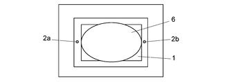
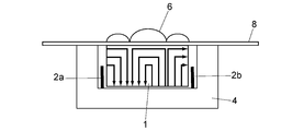
- FIG. 2A and 2B show schematic views of a rectangular microwave dielectric resonator.
- FIG. 2A is a plan view
- FIG. 2B is a vertical sectional view at a position passing through the antennas 2a and 2b.
- the dielectric resonator 1 is excited by one antenna 2a and outputs from the other antenna 2b.
- the resonator 1 and the antennas 2 a and 2 b are accommodated in the shield case 4.
- the resonance energy is confined inside the resonator 1, but a part of the resonance energy oozes out as an evanescent wave.
- the electric field distribution protruding on the surface of the resonator becomes parallel to the long side direction.
- it is used in such a resonance mode in which the electric field distribution is parallel to the long side direction.
- the resonance frequency shift amount is ⁇ f.
- the resonance frequency shift amount is defined as a value obtained by subtracting the resonance frequency f2 when there is a sample from the resonance frequency f1 when blank when there is no sample.
- the peak level at the resonance frequency position decreases corresponding to the dielectric loss rate of the sample simultaneously with the shift of the resonance frequency.
- the amount of change in peak level is ⁇ P.
- the peak level change amount is defined as a value obtained by subtracting the peak level P2 at the resonance frequency position when there is a sample from the peak level P1 at the resonance frequency position when blank when there is no sample.
- the frequency shift amount ⁇ f is proportional to ( ⁇ ′ ⁇ 1) ⁇ T
- the peak level change amount ⁇ P is ⁇ ′′ ⁇ It is proportional to T.
- the dielectric anisotropy can be obtained by arranging a plurality of rectangular dielectric resonators so that their directions are different from each other and detecting the amount of resonance frequency shift in each resonator.
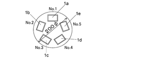
- FIG. 4 shows a layout example when, for example, five rectangular dielectric resonators 1a to 1e are arranged so as to have different directions ( ⁇ ) from the reference direction.
- the five resonators 1a to 1e are preferably arranged close to each other so that a place as close as possible can be measured.
- five resonators 1a to 1e are arranged in a circle having a diameter of 200 mm.
- the reference direction can be arbitrarily determined, but here, as an example, the moving direction (MD direction) of the sample is set as the reference direction.
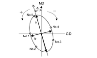
- the alignment pattern corresponding to this is shown in FIG. This is based on polar coordinates (r, ⁇ ) where the angle is ⁇ and the distance from the origin is r, the direction ( ⁇ ) of the resonators 1a to 1e is the angle ⁇ , and the resonance frequency shift amount ⁇ f detected by each resonator. Is plotted as r, and elliptic approximation is performed. Since the major axis direction of the ellipse indicates the maximum direction of the frequency shift amount, the dielectric constant of the sample is maximum in this direction. Therefore, fibers or molecular chains are arranged in this direction. The major axis direction of the ellipse is the orientation angle ( ⁇ ). On the other hand, the degree of orientation can be expressed by the difference or ratio between the major axis a and the minor axis b of the approximate ellipse.
- Patent Document 1 The invention described in Patent Document 1 was conceived as a secondary method and method for determining the fiber orientation or molecular orientation of a sheet-like material such as paper from the anisotropy of dielectric constant, and measuring the orientation.
- the basis weight can be measured. Therefore, when measuring the basis weight which is a scalar amount, the direction dependency of the dielectric constant becomes an obstacle.
- the resonance frequency shift amount is plotted on the polar coordinates, when the sample is not non-oriented, the value varies depending on the dependency of the sample on the dielectric constant direction as shown in FIG.
- the basis weight is a scalar, it does not have direction dependency.
- the first method for canceling the direction dependency of the resonance frequency shift amount due to the anisotropy of the dielectric constant is a method of simply averaging the resonance frequency shift amounts of a plurality of resonators.
- the resonance frequency shift amount ⁇ f is plotted on the polar coordinates as shown in FIG. 5, and the radius of a circle having the same area as that of an ellipsoid obtained by ellipse approximation is determined as the dielectric of the sample.
- This is a method of obtaining a converted shift amount ⁇ fr in which the mechanical anisotropy is canceled.
- a plurality of rectangular dielectric resonators (the number is n) arranged on only one surface side of a sheet-like sample are on the same plane so that their long side directions are different from the reference direction ( ⁇ ).
- the resonance frequencies f2 1 to f2 n of the resonators arranged above are measured, and the resonance frequency shift amounts ⁇ f 1 to ⁇ f n of the respective rectangular dielectric resonators are obtained for a certain sample.
- the shift amounts ⁇ f 1 to ⁇ f n are the differences between the resonance frequency f1 when there is no sample and the resonance frequencies f2 1 to f2 n of each rectangular dielectric resonator when there is a sample.
- an ellipse is drawn by the ellipse approximation process, and the area of the ellipse is obtained.
- this radius corresponds to the resonance frequency shift amount in which anisotropy is canceled.
- a plurality of (number of units) arranged only on one side of the sample as microwave resonators. n)) are arranged on the same plane so that the long side directions of the resonators are directed in different directions ( ⁇ ). Then, plotting on polar coordinates (r, ⁇ ) where the direction ( ⁇ ) is the angle ⁇ , the resonance frequency shift amounts ⁇ f 1 to ⁇ f n of those resonators are r, the angle is ⁇ , and the distance from the origin is r.
- ⁇ Pr calculated as a radius of a circle having the same area as the ellipse.
- the work of determining the calibration curve and the work of determining the constants A and B in the equation (2) indicating the relationship between ⁇ f, WT and BD can be executed by using an appropriate program on the computer.
- the absolute dry basis weight BD and the moisture content WT are measured by a BM meter as an example.
- ⁇ f and ⁇ P are measured for these standard samples by a measuring apparatus equipped with a microwave resonator.
- the calibration curve may be approximated by a quadratic function.
- the constant a is set to zero and the constants b and c are determined by the least square method.
- An example of the calibration curve obtained by approximating the calibration curve with a quadratic function is shown in FIG. ⁇ P on the horizontal axis is a measurement value obtained by a measurement apparatus equipped with a microwave resonator, and the vertical axis is a measurement value of the water content WT by a BM meter.
- the calibration curve in FIG. 7 shows a high value of 0.9897 for the determination coefficient R 2 (R is a correlation coefficient), indicating that the calibration curve is highly reliable.
- the water content WT can also be approximated by a multiple regression equation using ⁇ P and explanatory variables other than ⁇ P.
- explanatory variable other than ⁇ P for example, the dielectric loss of the absolutely dry portion of the sample can be mentioned.
- the operation of determining the constants A and B in the equation (2) indicating the relationship between ⁇ f, WT and BD is performed as follows.
- ⁇ f is calculated by applying quantities BD and WT obtained from a BM meter.
- the difference between the calculated value ⁇ f and the measured value ⁇ f measured using the microwave resonator is calculated for a plurality of standard samples, and the variance or standard deviation of the difference in ⁇ f is obtained.
- the variance or standard deviation is calculated in the same manner for another set of A and B (A, B).
- the set A and B (A, B) having the smallest variance or standard deviation is determined as the constants A and B in the equation (2).
- a program called “solver” one of the functions of spreadsheet software “Excel” manufactured by Microsoft Corporation
- the same basis weight / water content measuring apparatus includes a microwave resonator 100, a microwave excitation device 102 that generates an electric field vector in the resonator 100, and a detection device 104 that detects transmitted energy or reflected energy by the resonator 100.
- the resonance frequency f1 of the microwave resonator 100 in the first state where no sample is installed from the detection device 104, the peak level P1 at the position of the resonance frequency f1, and the microwave resonance in the second state where the sample is installed A data processing device 106 that takes in the resonance frequency f2 of the vessel 100 and the peak level P2 at the position of the resonance frequency f2 and calculates the absolute dry basis weight and moisture content of the sample.
- the data processing device 106 is realized by a dedicated computer of the measuring device or a computer such as a personal computer connected to the outside.
- the data processing apparatus 106 includes a ⁇ f / ⁇ P calculation unit 108, a constant / calibration curve determination unit 112, a constant / calibration curve storage unit 114, and an absolutely dry basis weight / water content calculation unit 120.
- the constant / calibration curve determination unit 112 is a calibration that indicates the relationship between ⁇ P and the moisture content WT from the moisture content WT separately obtained for a plurality of standard samples and the ⁇ P calculated by the ⁇ f / ⁇ P computation unit 108 for the corresponding standard samples.
- a combination of constants A and B is obtained such that ⁇ f obtained by applying to the above is the closest to ⁇ f calculated by the ⁇ f ⁇ ⁇ P calculating unit 108 for the corresponding standard sample.
- the constant / calibration curve storage unit 114 holds the constants A and B determined by the constant / calibration curve determination unit 112 and the calibration curve.
- the absolute dry basis weight / moisture amount calculation unit 120 applies ⁇ P calculated by the ⁇ f ⁇ ⁇ P calculation unit 108 to the calibration curve held in the constant / calibration curve storage unit 114 to obtain the moisture amount WT of the sample, WT calculated in this way, ⁇ f calculated by ⁇ f ⁇ ⁇ P calculation unit 108 and constants A and B held in constant / calibration curve storage unit 114 are applied to equation (2) to calculate the absolute dry basis weight of the sample.
- ⁇ P calculated by the ⁇ f ⁇ ⁇ P calculation unit 108 to the calibration curve held in the constant / calibration curve storage unit 114 to obtain the moisture amount WT of the sample, WT calculated in this way
- ⁇ f calculated by ⁇ f ⁇ ⁇ P calculation unit 108 and constants A and B held in constant / calibration curve storage unit 114 are applied to equation (2) to calculate the absolute dry basis weight of the sample.
- the constant / calibration curve determination unit 112 uses the absolute dry basis weight / moisture measuring device 110 other than the microwave resonator for a plurality of standard samples, or the microwave resonator is not a microwave resonator. Acquired by a method not using the absolutely dry basis weight / moisture measuring device 110.
- Such an absolutely dry basis weight / moisture measuring device 110 is not particularly limited, but an example thereof is a BM meter.
- the constant / calibration curve storage unit 114 stores the constants a, b, and c determined by the constant / calibration curve determination unit 112 as corresponding to the calibration curve. Is obtained by applying the constants a, b, and c held in the constant / calibration curve storage unit 114 to the equation (1A) as a calibration curve.
- the data processing device 106 further includes an air-dry basis weight / moisture content calculation unit 122 for obtaining an air-dry basis weight and a moisture content.
- the microwave resonator 100 is a plurality of rectangular dielectric resonators disposed only on one side of the sample, and the long side directions of these resonators are different directions ( ⁇ ). Are arranged on the same plane so as to face.
- the ⁇ f / ⁇ P calculation unit 108 calculates the above-described ⁇ fr and ⁇ Pr in which the anisotropy is canceled, and the absolutely dry basis weight / water content calculation unit 120 calculates the ⁇ fr calculated by the ⁇ f / ⁇ P calculation unit 108. And ⁇ Pr are used for calculation.
- FIGS. An embodiment of the measuring apparatus of the present invention is specifically shown in FIGS. This is an embodiment for realizing the present invention with an apparatus for measuring the dielectric anisotropy of a sample.
- Five dielectric resonators 1a to 1e are arranged, and the signal processing circuit shown in the block diagram of FIG. 8 is used to process the signal based on the time chart shown in FIG. 9 to measure the resonance frequency and the resonance peak level. To do.
- the signal output from the microwave sweeper oscillator 21 which is one of the microwave oscillation means is distributed to the dielectric resonators 1a to 1e via the isolators 22a to 22e.
- the outputs from the resonators 1a to 1e are converted into voltages by the respective detection diodes 23a to 23e, and the respective peak detection and averaging processing circuit units 25a are passed through the respective amplification and A / D conversion circuit units 24a to 24e. Enter 25e.
- the resonance frequency is measured as follows. As shown in FIG. 9, the microwave sweeper oscillator 21 sweeps the frequency. For example, the frequency can be continuously increased by sweeping the frequency at 250 MHz at 10 msec centering on 4 GHz. By the frequency sweep, the peak detection and averaging processing circuit units 25a to 25e can obtain a resonance curve from the microwave transmission intensity. The resonance curve is obtained as data of 100,000 pieces / 10 msec, and the peak position is obtained in a short time by using hardware based on VHDL (VHSIC Hardware Description Language). The peak detection and averaging processing circuit units 25a to 25e detect the start pulse portion from the sweep signal 21s, measure the time until the resonance level reaches the peak, and obtain the resonance frequency from the time by proportional calculation.
- VHDL VHSIC Hardware Description Language
- the sweep start timing can be detected by the start pulse portion that is the rising edge of the sweep signal, the time until reaching the peak level is measured, and the resonance frequency is measured by calculating from the sweep speed of 250 MHz in 10 msec. The This is repeated, for example, at a period of 50 msec, and is set to one resonance frequency on an average of 20 times.
- the sweep time for one time is as very short as 10 msec, and the signal is amplified at a high speed to perform digital processing.
- FIG. 10 shows the detection system circuit for one dielectric resonator in the circuit shown in FIG. 8 in more detail.
- the detection system circuit for the other dielectric resonators is the same.
- the amplification and A / D conversion circuit unit 24a described above includes, for example, an amplification circuit 31 and an A / D converter unit LSI32.
- the digital output from the amplification and A / D conversion circuit unit 24a enters the peak detection and average value processing circuit unit 25a.
- the peak detection and averaging processing circuit unit 25a includes a peak detection LSI and an averaging processing LSI.
- the peak detection LSI has a resonance peak level detection circuit. In this LSI, both resonance frequency and resonance peak level are detected as resonance peak detection, and the averaging processing LSI performs averaging processing of the resonance frequency and resonance peak level obtained for each sweep.
- the microcomputer 26 is connected to the subsequent stage of the peak detection and averaging processing circuit units 25a to 25e, and signals from each dielectric resonator detection system are input to the microcomputer 26.
- the microcomputer 26 collectively transmits the resonance frequency and resonance peak level from the peak detection and averaging processing circuit units 25a to 25e to the personal computer 27 in the subsequent stage.
- the microcomputer 26 also has a control function for controlling and operating each of the amplification and A / D conversion circuit units 24a to 24e and the peak detection and averaging processing circuit units 25a to 25e for each dielectric resonator system. .
- the personal computer 27 performs the function of the data processing device 106 that calculates the output from the microcomputer 26 and obtains the basis weight and water content to display or store the data as data.
- the amplification circuit 31 feeds back an RC circuit composed of the capacitor C1 and the resistor R2. Inserted into the line, absorbs and reduces ripple voltage, and obtains DC voltage with little fluctuation.
- the functions of the data processing apparatus realized by the personal computer 27 are those shown in FIG.
- Figure 11 shows the procedure for calculating ⁇ fr.
- the resonance frequency of the blank is obtained for each dielectric resonator and is defined as f 01 , f 02 , f 03 , f 04 , and f 05 , respectively.
- the resonance frequency of the sample is determined for each dielectric resonator and is set to f s1 , f s2 , f s3 , f s4 , and f s5 , respectively.
- the resonance frequency shift amount ⁇ f is calculated and set as ⁇ f 1 , ⁇ f 2 , ⁇ f 3 , ⁇ f 4 , ⁇ f 5 , respectively.
- This ⁇ fr is a resonance frequency shift amount in which the dielectric anisotropy is canceled.
- the peak level is not as anisotropic as the dielectric constant
- the amount of change in the peak level for one dielectric resonator with or without a sample may be adopted as ⁇ P, and the peak level for five dielectric resonators may be adopted.
- the peak levels P 01 to P 05 at the resonance frequency position of the blank are measured.
- the peak levels P S1 to P S5 at the resonance frequency position when there is a sample are measured.
- Peak level change amounts ⁇ P 1 to ⁇ P 5 are obtained for each resonator.
- ⁇ P 1 to ⁇ P 5 are displayed on polar coordinates, and the area of the ellipse is obtained by ellipse approximation processing.
- the radius of a circle having the same area as that of the ellipse is obtained, and the radius of the circle is set as a converted peak level change ⁇ Pr obtained by canceling the dielectric anisotropy of the sample.
- the resonance frequency shift amount ⁇ f and the peak level change amount ⁇ P are measured by a measuring device using a microwave resonator, and, for example, an absolutely dry basis weight (BD) is measured with a BM meter.
- the calibration curve is obtained from, for example, the amount of moisture (WT) measured with a BM meter and the peak level change ⁇ P obtained for the corresponding standard sample using a microwave resonator. Constants a, b, and c are determined assuming that the calibration curve is approximated by a cubic function such as the expression (1A).
- the constants A and B in the relational expression (2) for obtaining the absolute dry basis weight were calculated by applying the absolute dry basis weight (BD) and the water content (WT) measured by a BM meter, for example, to the expression (2) ⁇ f Is determined as a combination of constants A and B that are closest to the measured value ⁇ f obtained using the microwave resonator for the corresponding standard sample.
- FIG. 14 shows the operation for obtaining the absolute dry basis weight and moisture content, and further the air dry basis weight and moisture content in this example.
- the resonance frequency and resonance peak level in the microwave resonator when there is no sample are measured.
- the sample is arranged by the same microwave resonator and the resonance frequency and the resonance peak level are measured (step S1).
- the resonance frequency shift amount ⁇ fr and the resonance peak level change amount ⁇ Pr related to the presence / absence of the sample are obtained (step S2).
- the moisture amount WT is calculated by substituting ⁇ Pr as ⁇ P into the equation (1A) (step S4).
- the absolute dry basis weight BD is calculated by substituting ⁇ fr as ⁇ f and WT calculated in step S4 into the equation (2) (step S5).
- step S6 the air-dried basis weight and moisture content are calculated using the above formulas (7) and (8) (step S6).
- FIG. 15 shows the result of obtaining the moisture content for a plurality of samples by the apparatus of the embodiment of the present invention on an actual paper machine, and the result of measuring the moisture content by a BM meter for the sample is shown in FIG. Shown on the axis.
- the determination coefficient R 2 has a high value of 0.9897. From this, it is understood that the water content can be measured with high accuracy according to the present invention.
Landscapes
- Physics & Mathematics (AREA)
- Life Sciences & Earth Sciences (AREA)
- Chemical & Material Sciences (AREA)
- Health & Medical Sciences (AREA)
- General Health & Medical Sciences (AREA)
- Analytical Chemistry (AREA)
- Biochemistry (AREA)
- General Physics & Mathematics (AREA)
- Immunology (AREA)
- Pathology (AREA)
- Medicinal Chemistry (AREA)
- Food Science & Technology (AREA)
- Engineering & Computer Science (AREA)
- Electromagnetism (AREA)
- Measurement Of Resistance Or Impedance (AREA)
Abstract
サンプルを設置しない第1の状態でのマイクロ波共振器における共振周波数f1、共振ピークレベルP1と、サンプルを設置した第2の状態での前記マイクロ波共振器における共振周波数f2、共振ピークレベルP2を測定し、共振周波数シフト量Δf(=f1-f2)とピークレベル変化量ΔP(=P1-P2)を求める。水分量WTは、ΔPと水分量WTとの関係を示す検量線を用いて求める。絶乾坪量BDは、Δf、WT及びBDの関係を示す Δf=A・BD+B・WT(AとBは定数) を用いて、Δfと検量線から求めたWTとから求める。
Description
本発明は、紙、不織布、フィルムをはじめとするシート状物質、特に紙シートの坪量(1平方メートル当たりの重量)と水分量をオンラインで測定する方法と装置に関するものである。
紙の製造工程において、坪量をオンラインで測定することは非常に重要であり、坪量は紙の品質上及び商取引上の重要な管理項目となっている。坪量だけでなく、水分率も重要な項目となっている。従来、BM計(Basis Weight & Moisture Measurement System)を用い、紙の坪量はβ線の透過減衰量から、紙の水分は近赤外線の吸収量から求めるのが一般的である。BM計による坪量測定値は最も信頼性が高いとされている。
坪量を測るには、Kr85(クリプトン)又はPm147(プロメシューム)などの放射線源から得られるβ線を用いている。坪量が大きいとβ線の減衰量が大きく、坪量が小さいと減衰量が小さいため、β線の透過量と坪量とは反比例に近い関係にある。坪量を正確に求めるには、β線の透過量と坪量との関係を示す検量線が用いられる。
水分を測る近赤外線としては、通常、基準光、測定光及び補正光の3種類が用いられている。基準光は波長が1.8μmであり、この波長光は水分により減衰しない。測定光は波長が1.9μmであり、この波長光は水分により減衰する。補正光は波長が2.1μmであり、この波長光はセルロースによる影響を受けない。水分による測定光の減衰量と水分量との関係を予め検量線として調べておくことによって、正確な水分量が求められる。
従来のBM計の坪量測定においてはβ線を用いるため、線源としてクリプトン85又はプロメシューム147などの放射線源を用いなければならない。放射線源は人体に悪影響を及ぼす可能性がある。そのため、測定時には線源に近づかないように立入り禁止区域を設け、また近辺で作業する機会の多い人にはフィルムバッチの携帯を義務付け、浴びた放射線量を定期的にチェックしなければならない。また、放射線を取り扱うことができる主任技術者を配置する必要があり、放射線の取扱いに十分な注意と専門知識が要求される。
放射線源を用いることによるこのような課題を回避する方法として、本発明者らは放射線を使用しないで紙などのシート状物質の坪量及び水分を測定する方法を提案している(特許文献1参照。)。その提案の方法は、マイクロ波誘電体共振器を用いて坪量と水分を同時に測定するものであり、紙の繊維配向などのサンプルの誘電的異方性をオンラインで測る装置の応用として、繊維配向以外に坪量及び水分量も同時に測定できることを示したものである。その提案の方法によれば、坪量はサンプルがないときの共振周波数とサンプルを配置したときの共振周波数との差である共振周波数シフト量から求められ、水分量はサンプルがないときの共振周波数でのピークレベルとサンプルを配置したときの共振周波数でのピークレベルとの差である共振ピークレベル変化量から求められる。
さらに、本発明者らは坪量と水分量又は水分率を求める具体的な方法も提案している(特許文献2参照。)。その提案の具体的な方法を概略的に示すと以下のようになる。
マイクロ波共振器を用いると、サンプルの有無により図3のように共振周波数シフト量Δfと共振ピークレベル変化量ΔPが現れる。サンプルの厚みをTとすると、共振周波数シフト量Δfは((誘電率-1)×T)に比例し、共振ピークレベル変化量ΔPは(誘電損失率×T)に比例する。
一方、図6のように紙を絶乾部分と水とに分離したモデルを考え、測定している絶乾部分の体積をV1、水の体積をV2とすると、以下の式が成立する。
Δf=Kf(V1・ε’1+V2・ε’2) (3)
ΔP=Kp(V1・ε”1+V2・ε”2) (4)
ここで、Kf、Kpはディメンジョンを合わせるための比例定数、ε’1は絶乾の紙の誘電率-1、ε’2は水の誘電率、ε”1は絶乾の紙の誘電損失率、ε”2は水の誘電損失率(周波数、束縛の程度、温度によっても変わる)である。
Δf=Kf(V1・ε’1+V2・ε’2) (3)
ΔP=Kp(V1・ε”1+V2・ε”2) (4)
ここで、Kf、Kpはディメンジョンを合わせるための比例定数、ε’1は絶乾の紙の誘電率-1、ε’2は水の誘電率、ε”1は絶乾の紙の誘電損失率、ε”2は水の誘電損失率(周波数、束縛の程度、温度によっても変わる)である。
ΔfとΔPの実測データを用いて上の連立方程式(3),(4)を解くことによりV1とV2を求める。そして、V1,V2と絶乾坪量(BD)、水分量(WT)との間には、
絶乾坪量(BD)=β・V1 (5)
水分量(WT)=γ・V2 (6)
(βは絶乾状態の紙の比重、γは水の比重)の関係があることから、V1から絶乾坪量、V2から水分量をそれぞれ求める。これが特許文献2で提案の方法である。
絶乾坪量(BD)=β・V1 (5)
水分量(WT)=γ・V2 (6)
(βは絶乾状態の紙の比重、γは水の比重)の関係があることから、V1から絶乾坪量、V2から水分量をそれぞれ求める。これが特許文献2で提案の方法である。
JIS P8124(1956年制定、2011年改定)
JIS P8127(1958年制定、2010年改定)
本発明は、特許文献2に記載の方法とは異なる方法により、マイクロ波共振器を用いて紙の坪量と水分量を求める新しい方法と装置を提供することを目的とするものである。
本発明の坪量・水分量測定方法は、以下のステップS1からS3を含んでいる。
(ステップS1)サンプルを設置しない第1の状態でのマイクロ波共振器における共振周波数f1、共振ピークレベルP1と、サンプルを設置した第2の状態での前記マイクロ波共振器における共振周波数f2、共振ピークレベルP2を測定し、共振周波数シフト量Δf(=f1-f2)とピークレベル変化量ΔP(=P1-P2)を求めるステップ、
(ステップS2)ΔPと水分量WTとの関係を示す検量線(1)
WT=F(ΔP) (1)
(F(ΔP)はΔPの関数)
を用い、ステップS1で求めたΔPから前記サンプルの水分量WTを求めるステップ、及び
(ステップS3)Δf、WT及びBDの関係を示す以下の式(2)
Δf=A・BD+B・WT (2)
(AとBは定数である。)
を用いて、ステップS1で求めたΔfとステップS2で求めたWTとから前記サンプルの絶乾坪量BDを求めるステップ。
(ステップS1)サンプルを設置しない第1の状態でのマイクロ波共振器における共振周波数f1、共振ピークレベルP1と、サンプルを設置した第2の状態での前記マイクロ波共振器における共振周波数f2、共振ピークレベルP2を測定し、共振周波数シフト量Δf(=f1-f2)とピークレベル変化量ΔP(=P1-P2)を求めるステップ、
(ステップS2)ΔPと水分量WTとの関係を示す検量線(1)
WT=F(ΔP) (1)
(F(ΔP)はΔPの関数)
を用い、ステップS1で求めたΔPから前記サンプルの水分量WTを求めるステップ、及び
(ステップS3)Δf、WT及びBDの関係を示す以下の式(2)
Δf=A・BD+B・WT (2)
(AとBは定数である。)
を用いて、ステップS1で求めたΔfとステップS2で求めたWTとから前記サンプルの絶乾坪量BDを求めるステップ。
検量線(1)を決定するためのWTと、定数A、Bを決定するためのBDとWTは、複数の標準サンプルについてマイクロ波共振器以外の装置、例えばBM計を用いて、又はマイクロ波共振器もマイクロ波共振器以外の前記装置も用いない方法により別途取得する。そして、検量線(1)は、別途取得したWTと該当する標準サンプルについて前記マイクロ波共振器を用いて得られた測定値ΔPとから求め、定数A、Bは、別途取得したBDとWTを(2)式に当てはめて得られたΔfが、該当する標準サンプルについて前記マイクロ波共振器を用いて得られた測定値Δfに最も近くなるような定数A、Bの組み合わせとして求める。
BDとWTを別途求めるためのマイクロ波共振器以外の装置として、例えばBM計を用いることができる。BM計は放射線源を用いるが、BM計を使用するとしても本発明ではBM計を使用するのは検量線と定数A、Bを決めるための標準サンプルを測定するときだけである。いったん検量線と定数A、Bが決まれば、その後の実際のサンプルの測定時にはマイクロ波共振器を備えた測定装置を使用するだけであり、もはやBM計は必要ではない。そのため、本発明では放射線源を用いることによる前述の問題はない。
マイクロ波共振器もBM計などのマイクロ波共振器以外の装置も用いない方法の一例として、絶乾坪量は「紙及び板紙?坪量の測定方法、JIS P8124(1956年制定、2011年改定)」(非特許文献1参照。)の付属書Aに規定されている絶乾坪量の測定方法に記載の方法が挙げられ、水分は「紙及び板紙?ロットの水分試験方法?乾燥器による方法、JIS P8127(1958年制定、2010年改定)」(非特許文献2参照。)に規定されている方法が挙げられる。これらの日本工業規格の測定方法は、いずれもオフライン用の測定方法であって、BM計の検定を行う際に実施されるものである。
日本工業規格の測定方法に基づく絶乾坪量の測定方法は、以下のように行う。
(1)採取したシート状試料の面積をあらかじめ測定する。
(2)試料を熱した乾燥機に入れて重量変化がなくなるまで含有水分を十分に除去し、すぐに試料重量を測定する。
(3)絶乾坪量を、乾燥後の試料重量を、加熱前に測定した試料面積で割ることにより得る。
日本工業規格の測定方法に基づく水分の測定方法は以下のように行う。
(1)採取したシート状試料の面積及び重量をあらかじめ測定する。
(2)絶乾坪量の測定方法と同様に試料を熱した乾燥機に入れて重量変化がなくなるまで含有水分を十分に除去し、すぐに試料重量を測定する。
(3)水分率を求める場合は下記(a)式、水分量を求める場合は下記(b)式により計算する。
水分率=[(加熱前の試料重量-加熱後の試料重量)/(加熱前の試料重量)]×100(a)
水分量=(加熱前の試料重量-加熱後の試料重量)/(加熱前の試料面積) (b)
(1)採取したシート状試料の面積をあらかじめ測定する。
(2)試料を熱した乾燥機に入れて重量変化がなくなるまで含有水分を十分に除去し、すぐに試料重量を測定する。
(3)絶乾坪量を、乾燥後の試料重量を、加熱前に測定した試料面積で割ることにより得る。
日本工業規格の測定方法に基づく水分の測定方法は以下のように行う。
(1)採取したシート状試料の面積及び重量をあらかじめ測定する。
(2)絶乾坪量の測定方法と同様に試料を熱した乾燥機に入れて重量変化がなくなるまで含有水分を十分に除去し、すぐに試料重量を測定する。
(3)水分率を求める場合は下記(a)式、水分量を求める場合は下記(b)式により計算する。
水分率=[(加熱前の試料重量-加熱後の試料重量)/(加熱前の試料重量)]×100(a)
水分量=(加熱前の試料重量-加熱後の試料重量)/(加熱前の試料面積) (b)
以上の二つの測定方法において、試料重量を測定する際には、試料に含まれる水分の変化が測定誤差に起因するため、重量測定時の水分変化を防ぐ目的で秤量瓶を用いるなど、十分に注意を払う必要がある。
ここで、(2)式を導出する過程を説明する。(3)式について、V1とV2をそれぞれ(5),(6)に基づいてBD(絶乾坪量)とWT(水分量)として書き換えると、次の(3A)式となる。
Δf=Kf((BD/β)・ε’1+(WT/γ)・ε’2) (3A)
ここで(3A)式の定数部分をまとめると(2)式となる。
Δf=A・BD+B・WT (2)
Δf=Kf((BD/β)・ε’1+(WT/γ)・ε’2) (3A)
ここで(3A)式の定数部分をまとめると(2)式となる。
Δf=A・BD+B・WT (2)
(1)式は、ΔPと水分量WTとの関係を示す検量線をΔPの関数とする一般式で表わしたものである。一実施形態では、検量線の具体的な一例として、以下の近似式
WT=a・ΔP3+b・ΔP2+c・ΔP (1A)
で表わされるものを使用する。この場合、検量線の決定は、複数の標準サンプルについて別途取得したWTと該当する標準サンプルについてマイクロ波共振器を用いて得られた測定値ΔPを(1A)式に当てはめて、定数a、b、cを決定することに相当する。
WT=a・ΔP3+b・ΔP2+c・ΔP (1A)
で表わされるものを使用する。この場合、検量線の決定は、複数の標準サンプルについて別途取得したWTと該当する標準サンプルについてマイクロ波共振器を用いて得られた測定値ΔPを(1A)式に当てはめて、定数a、b、cを決定することに相当する。
他の実施形態では、さらに、以下の式を用いて、風乾坪量(g/m2)及び水分率(%)まで求める。絶乾坪量とは、水分率が0%のときにおける坪量を意味する。
風乾坪量=絶乾坪量BD+水分量WT (7)
水分率=水分量WT×100/風乾坪量 (8)
風乾坪量=絶乾坪量BD+水分量WT (7)
水分率=水分量WT×100/風乾坪量 (8)
本明細書では、水分の量に関する用語として「水分率」と「水分量」を同等なものとしてともに使用している。「水分率」と「水分量」は、(7),(8)式から、次の関係がある。
水分率=(水分量WT/(絶乾坪量BT+水分量WT))×100
水分率=(水分量WT/(絶乾坪量BT+水分量WT))×100
本発明の坪量・水分量測定装置は、マイクロ波共振器と、前記マイクロ波共振器に電界ベクトルを発生させるマイクロ波用励振装置と、前記マイクロ波共振器による透過エネルギー又は反射エネルギーを検出する検出装置と、前記検出装置からサンプルを設置しない第1の状態での前記マイクロ波共振器の共振周波数f1とその共振周波数f1位置でのピークレベルP1と、サンプルを設置した第2の状態での前記マイクロ波共振器の共振周波数f2とその共振周波数f2位置でのピークレベルP2を取り込み、前記サンプルの絶乾坪量と水分量を算出するデータ処理装置とを備えている。データ処理装置の詳しい構成は後述する。
本発明によれば、マイクロ波共振器を用いて紙などのシート状物質の坪量及び水分量(水分率)を測定する際に、放射線を使用せず、安全に測定できる。
まず、坪量及び水分量(又は水分率)を測定する装置の概要について説明する。
マイクロ波共振器を用いて紙の繊維配向を測定するのではなく、紙の坪量と水分量を測定する場合には、誘電率の異方性をキャンセルする必要がある。キャンセルする方法としては、例えば1個のマイクロ波共振器を使用する方法がある。マイクロ波共振器は空洞共振器であっても誘電体共振器であってもよい。この場合、空洞共振器の場合は円筒空洞共振器や球形空洞共振器などを用いて、例えば電界ベクトルがループ状になるTE011モードのように、電界ベクトルがある方向に偏らない共振モードを選択する。誘電体共振器の場合は、エバネセント波の電界ベクトルがある一定方向に偏って向くのではなく、円柱型誘電体共振器を用いて四方八方に向く電界分布、又はループ状となる電界分布などの電界分布となる共振モードを選択するのが望ましいのは当然である。この場合はサンプルがないときとあるときにおける共振器によって得られる共振周波数シフト量と共振ピークレベル変化量をそのまま用いて坪量と水分量を算出することができる。
オンラインで紙の繊維配向などのサンプルの誘電的異方性を測る装置の応用として坪量及び水分量も測定する場合には、逆にサンプルの誘電率異方性の影響を受けてしまう問題がある。誘電率はテンソルであるため方向によって値が異なるが、坪量や水分量はスカラー量であるため方向によって値が異なることはない。坪量又は水分量を測定するときにこの誘電率異方性をいかにキャンセルするかが課題である。
サンプルの誘電的異方性を測る装置でサンプルの誘電率異方性をキャンセルする方法を説明する。図2Aと図2Bに矩形のマイクロ波誘電体共振器の概観図を示す。図2Aは平面図、図2Bはそのアンテナ2a、2bを通る位置での垂直断面図である。誘電体共振器1が一方のアンテナ2aにより励振され、もう一方のアンテナ2bから出力を出す。共振器1やアンテナ2a,2bはシールドケース4内に収容されている。
ほとんどの共振エネルギーは共振器1の内部に閉じ込められているが、一部はエバネセント波として表面に滲み出している。矩形の誘電体共振器の場合、共振モードを適切に選択することによって、共振器表面に沁み出した電界分布は長辺方向と平行になる。ここでは電界分布が長辺方向と平行になるそのような共振モードで使用する。エバネセント波6の電界ベクトルのほとんどすべてが平行になっていると、サンプル8の誘電率異方性、つまり配向性を測定することが可能になる。
誘電体共振器1の上面にサンプル8を近接又は接触させて配置すると、エバネセント波6の電界ベクトル方向の誘電率に対応して図3のように共振周波数が低周波数側にシフトする。その共振周波数シフト量をΔfとする。共振周波数シフト量はサンプルがない場合のブランク時の共振周波数f1からサンプルがあるときの共振周波数f2を引いた値と定義される。
誘電体共振器1の上面にサンプル8を近接又は接触させて配置すると、共振周波数のシフトと同時に、サンプルの誘電損失率に対応して共振周波数位置でのピークレベルが下がる。そのピークレベル変化量をΔPとする。ピークレベル変化量はサンプルがない場合のブランク時の共振周波数位置でのピークレベルP1からサンプルがあるときの共振周波数位置でのピークレベルP2を引いた値と定義される。サンプルの誘電率をε’、誘電損失率をε”、サンプルの厚みをTとすると、周波数シフト量Δfは(ε’-1)×Tに比例し、ピークレベル変化量ΔPは、ε”×Tに比例する。
配向性を測定する場合は、誘電率の異方性を見ればよい。そこで、複数の矩形誘電体共振器を互いに方向が異なるように配置し、各共振器における共振周波数シフト量を検知すれば、誘電率異方性がわかる。
図4に、例えば5個の矩形誘電体共振器1a~1eを基準方向から互いに異なる方向(θ)をもつように配置した場合のレイアウト例を示す。5個の共振器1a~1eはなるべく近い場所を測定できるように互いに接近して配置することが好ましい。この例では、直径200mmの円内に5個の共振器1a~1eを配置している。基準方向は任意に定めることができるが、ここでは一例としてサンプルの移動方向(MD方向)を基準方向とする。
これに対応した配向パターンを図5に示す。これは角度をθ、原点からの距離をrとする極座標(r,θ)上に、共振器1a~1eの方向(θ)を角度θとし、それぞれの共振器が検出した共振周波数シフト量Δfをrとしてプロットし、楕円近似を行ったものである。楕円の長軸方向が周波数シフト量の最大方向を示すため、この方向でサンプルの誘電率が最大となる。したがって、この方向に繊維又は分子鎖が並んでいることになる。楕円の長軸方向が配向角度(φ)である。一方、配向度は近似した楕円の長軸aと短軸bの差又は比で表すことができる。
特許文献1に記載の発明は、紙などのシート状物質の繊維配向又は分子配向を誘電率の異方性から求める方法と装置の副次的なものとして考え出されたものであり、配向測定と同時に坪量も測定できるというものである。そのために、スカラー量である坪量を測定する場合、誘電率の方向依存性が逆に障害となる。共振周波数シフト量を極座標上にプロットすると、サンプルが無配向でない場合、例えば図5のようにサンプルの誘電率方向依存性によって異なる値になる。しかし、坪量はスカラーであるため、方向依存性を有しない。
その誘電率の異方性に起因する共振周波数シフト量の方向依存性をキャンセルする第1の方法は、複数個の共振器の共振周波数シフト量を単純に平均化処理する方法である。
方向依存性をキャンセルする第2の方法として、図5のように共振周波数シフト量Δfを極座標上にプロットし、楕円近似をしてできる楕円体の面積と同面積の円の半径をサンプルの誘電的異方性をキャンセルした換算シフト量Δfrとする方法である。例えば、シート状サンプルの一面側のみに配置された複数個(個数をnとする。)の矩形誘電体共振器をその長辺方向がそれぞれ基準方向から異なる方向(θ)を向くように同一平面上に配置してそれぞれの共振器の共振周波数f21~f2nを測定し、あるサンプルについて各矩形誘電体共振器の共振周波数シフト量Δf1~Δfnを求める。シフト量Δf1~Δfnは、先に定義したように、サンプルがない場合の共振周波数f1とサンプルがある場合の各矩形誘電体共振器の共振周波数f21~f2nとの差である。次に、角度をθ、原点からの距離をrとする極座標(r,θ)上に、前記方向(θ)を角度θとし、シフト量Δf1~Δfnをrとしてプロットし、図5のように楕円近似処理により楕円を描き、その楕円の面積を求める。その楕円の面積と同面積の円の半径を求めると、この半径が異方性をキャンセルした共振周波数シフト量に相当する。
サンプルの誘電的異方性を測る装置で本発明の一実施形態の坪量・水分量測定方法を実施する場合は、マイクロ波共振器としてサンプルの一面側のみに配置された複数個(個数をnとする。)の矩形誘電体共振器を、それらの共振器の長辺方向がそれぞれ異なる方向(θ)を向くように同一平面上に配置する。そして、方向(θ)を角度θとしそれらの共振器の共振周波数シフト量Δf1~Δfnをrとして、角度をθ、原点からの距離をrとする極座標(r,θ)上にプロットし、楕円近似処理により楕円を描き、その楕円の面積と同面積の円の半径Δfrを求めて、そのΔfrを(2)式中のΔfとする。また、それらの共振器のピークレベル変化量ΔP1~ΔPnを求め、次の(A)から(C)のいずれかのΔPrを(1)式中のΔPとする。
(A)ΔP1~ΔPnのいずれかからなるΔPr。
(B)ΔP1~ΔPnの平均値からなるΔPr。
(C)前記方向(θ)を角度θとしΔP1~ΔPnをrとして、角度をθ、原点からの距離をrとする極座標(r,θ)上にプロットし、楕円近似処理により楕円を描き、その楕円の面積と同面積の円の半径として求めたΔPr。
(A)ΔP1~ΔPnのいずれかからなるΔPr。
(B)ΔP1~ΔPnの平均値からなるΔPr。
(C)前記方向(θ)を角度θとしΔP1~ΔPnをrとして、角度をθ、原点からの距離をrとする極座標(r,θ)上にプロットし、楕円近似処理により楕円を描き、その楕円の面積と同面積の円の半径として求めたΔPr。
以下の説明では、上記いずれかの方法で誘電的異方性をキャンセルした周波数シフト量Δfが得られたという前提で記述する。
検量線を決定する作業と、Δf、WT及びBDの関係を示す(2)式中の定数A,Bを決定する作業は、コンピュータ上で適当なプログラムを使用することにより実行することができる。
まず、複数の標準サンプルについて、一例としてBM計により絶乾坪量BDと水分量WTを測定する。一方、それらの標準サンプルについてマイクロ波共振器を備えた測定装置によりΔfとΔPを測定する。
検量線を表わす関数WT=F(ΔP)は、ΔPの一次関数にならないことがわかった。2次関数又は3次関数で近似することができる。そこで、例えば(1A)式のような3次関数で近似し、測定値WTとΔPを当てはめて最小二乗法により定数a、b、cを決定する。
また、検量線を2次関数で近似してもよい。その場合は定数aをゼロにして、最小二乗法により定数b、cを決定する。このように、検量線を2次関数で近似して求めた検量線の一例を図7に示す。横軸のΔPはマイクロ波共振器を備えた測定装置による測定値、縦軸はBM計による水分量WTの測定値である。図7の検量線は決定係数R2(Rは相関係数)が0.9897という高い値を示しており、検量線として信頼性の高いものであることを示している。
なお、水分量WTは、ΔPと、ΔP以外の説明変数による、重回帰式で近似することもできる。ΔP以外の説明変数としては、例えば、サンプルの絶乾部分の誘電損失が挙げられる。
Δf、WT及びBDの関係を示す(2)式中の定数A,Bを決定する作業は、次のように行う。ある一つの定数A,Bの組(A,B)について、例えばBM計から得られた量BDとWTを当てはめてΔfを計算する。その計算値Δfとマイクロ波共振器を用いて測定された測定値Δfとの差を複数の標準サンプルについて計算し、Δfの差の分散又は標準偏差を求める。別のA,Bの組(A,B)についても同様に分散又は標準偏差を計算する。種々のA,Bの組(A,B)のうち、分散又は標準偏差が最も小さくなったA,Bの組(A,B)を(2)式中の定数A,Bとして決定する。このような計算のプログラムの一例として、「ソルバー」(マイクロソフト社製表計算ソフト「エクセル」の機能の1つ)と称されるプログラムを使用することができる。
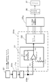
本発明の坪量・水分量測定装置の一実施形態を、図1を参照して説明する。同坪量・水分量測定装置は、マイクロ波共振器100と、共振器100に電界ベクトルを発生させるマイクロ波用励振装置102と、共振器100による透過エネルギー又は反射エネルギーを検出する検出装置104と、検出装置104からサンプルを設置しない第1の状態でのマイクロ波共振器100の共振周波数f1とその共振周波数f1位置でのピークレベルP1と、サンプルを設置した第2の状態でのマイクロ波共振器100の共振周波数f2とその共振周波数f2位置でのピークレベルP2を取り込み、サンプルの絶乾坪量と水分量を算出するデータ処理装置106とを備えている。
データ処理装置106はこの測定装置の専用のコンピュータにより、又は外部に接続されたパーソナルコンピュータなどのコンピュータにより実現されるものである。データ処理装置106は、Δf・ΔP算出部108、定数/検量線決定部112、定数/検量線記憶部114及び絶乾坪量・水分量算出部120を備えている。
Δf・ΔP算出部108は、検出装置104から取り込んだ共振周波数f1,f2とピークレベルP1,P2から共振周波数シフト量Δf(=f1-f2)とピークレベル変化量ΔP(=P1-P2)を算出する。
定数/検量線決定部112は、複数の標準サンプルについて別途取得した水分量WTと該当する標準サンプルについてΔf・ΔP算出部108で算出されたΔPとからΔPと水分量WTとの関係を示す検量線を求め、複数の標準サンプルについて別途取得した絶乾坪量BDとWTをΔf、WT及びBDの関係を示す以下の式(2)
Δf=A・BD+B・WT (2)
に当てはめて得られたΔfが、該当する標準サンプルについてΔf・ΔP算出部108で算出されたΔfに最も近くなるような定数A,Bの組み合わせを求める。
Δf=A・BD+B・WT (2)
に当てはめて得られたΔfが、該当する標準サンプルについてΔf・ΔP算出部108で算出されたΔfに最も近くなるような定数A,Bの組み合わせを求める。
定数/検量線記憶部114は、定数/検量線決定部112で決定された定数A,Bと検量線を保持する。
絶乾坪量・水分量算出部120は、Δf・ΔP算出部108で算出されたΔPを定数/検量線記憶部114に保持されている検量線に当てはめてサンプルの水分量WTを求め、そのように求められたWT、Δf・ΔP算出部108で算出されたΔf及び定数/検量線記憶部114に保持されている定数A,Bを式(2)に当てはめてサンプルの絶乾坪量を求める。
定数/検量線決定部112は、BDとWTを、複数の標準サンプルについてマイクロ波共振器以外の絶乾坪量・水分測定装置110を用いて、又はマイクロ波共振器もマイクロ波共振器以外の絶乾坪量・水分測定装置110も用いない方法により取得する。そのような絶乾坪量・水分測定装置110は特に限定されるものではないが、その一例はBM計である。
好ましい実施形態では、定数/検量線決定部112は、検量線を以下の近似式
WT=a・ΔP3+b・ΔP2+c・ΔP (1A)
に当てはめて定数a、b、cを決定するものである。その場合、定数/検量線記憶部114は検量線に相当するものとして定数/検量線決定部112が決定した定数a、b、cを記憶するものとなり、絶乾坪量・水分量算出部120は定数/検量線記憶部114に保持されている定数a、b、cを(1A)式に当てはめたものを検量線として用いて水分量WTを求めるものとなる。
WT=a・ΔP3+b・ΔP2+c・ΔP (1A)
に当てはめて定数a、b、cを決定するものである。その場合、定数/検量線記憶部114は検量線に相当するものとして定数/検量線決定部112が決定した定数a、b、cを記憶するものとなり、絶乾坪量・水分量算出部120は定数/検量線記憶部114に保持されている定数a、b、cを(1A)式に当てはめたものを検量線として用いて水分量WTを求めるものとなる。
他の好ましい実施形態では、データ処理装置106は風乾坪量と水分率を求める風乾坪量・水分率算出部122をさらに備えている。
さらに他の好ましい実施形態では、マイクロ波共振器100はサンプルの一面側のみに配置される複数個の矩形誘電体共振器であって、それらの共振器の長辺方向がそれぞれ異なる方向(θ)を向くように同一平面上に配置されたものである。その場合、Δf・ΔP算出部108は異方性がキャンセルされた前述のΔfrとΔPrを算出するものとなり、絶乾坪量・水分量算出部120はΔf・ΔP算出部108により算出されたΔfrとΔPrを用いて演算を行うものとなる。
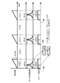
本発明の測定装置の一実施例を図8から図10により具体的に示す。これはサンプルの誘電的異方性を測る装置で本発明を実現する実施例である。5個の誘電体共振器1a~1eを配置し、図8のブロック図で示す信号処理回路を用いて、図9に示すタイムチャートに基づいて信号を処理して共振周波数と共振ピークレベルを測定する。
マイクロ波発振手段の一つであるマイクロ波スイーパ発振器21から出た信号を、アイソレータ22a~22eを介して誘電体共振器1a~1eに分配している。各共振器1a~1eからの出力はそれぞれの検波ダイオード23a~23eで電圧に変換され、それぞれの増幅及びA/D変換回路部24a~24eを通ってそれぞれのピーク検出及び平均化処理回路部25a~25eに入る。
共振周波数の測定は次のように行われる。図9に示したようにマイクロ波スイーパ発振器21が周波数を掃引する。例えば周波数を、4ギガヘルツを中心に10msecで250MHz掃引することによって連続的に周波数が上げられる。その周波数掃引により、ピーク検出及び平均化処理回路部25a~25eではマイクロ波透過強度から共振カーブが得られる。共振カーブは100000個/10msecのデータとして得られ、そのデータからVHDL(VHSIC Hardware Description Language)によるハードウエアでピーク位置が短時間で求められる。ピーク検出及び平均化処理回路部25a~25eはそのスイープ信号21sからスタートパルス部分を検知して共振レベルがピークに達するまでの時間を測定し、その時間から比例計算によって共振周波数を求める。
この方法では、掃引開始タイミングをスイープ信号の立ち上がりであるスタートパルス部分によって検知できるため、そこからピークレベルに達するまでの時間を計測し、10msecで250MHzの掃引速度から計算して共振周波数が測定される。これを、例えば50msecの周期で繰り返し、20回平均で1つの共振周波数としている。このように1回の掃引時間は10msecと非常に短く、高速で信号を増幅し、デジタル処理を行っているわけである。
図10に図8に示した回路中の一つの誘電体共振器についての検出系の回路をさらに詳細に示した。他の誘電体共振器についての検出系の回路も同じである。先に説明した増幅及びA/D変換回路部24aは、一例としては増幅回路31とA/Dコンバータ部LSI32からなる。増幅及びA/D変換回路部24aからのデジタル出力はピーク検出及び平均値化処理回路部25aに入る。ピーク検出及び平均化処理回路部25aは、一例としてはピーク検出LSIと平均化処理LSIからなる。ピーク検出LSIは正確に言えば共振ピークレベル検出回路ももっている。このLSIにおいて共振ピーク検出として共振周波数と共振ピークレベルの両方を検出し、平均化処理LSIではスイープ毎に得られる共振周波数と共振ピークレベルの平均化処理を行っている。
ピーク検出及び平均化処理回路部25a~25eの後段にはマイクロコンピュータ26が接続され、各誘電体共振器検出系からの信号がマイクロコンピュータ26に入力される。マイクロコンピュータ26はピーク検出及び平均化処理回路部25a~25eからの共振周波数と共振ピークレベルをまとめて後段のパーソナルコンピュータ27に送信する。マイクロコンピュータ26はまた、各増幅及びA/D変換回路部24a~24e、ピーク検出及び平均化処理回路部25a~25eを誘電体共振器系毎に制御して動作させるための制御機能ももっている。
パーソナルコンピュータ27はマイクロコンピュータ26からの出力を演算して坪量と水分量を求めてデータとして表示したり記憶したりするデータ処理装置106の機能を果たす。
ここで、図10において、増幅及びA/D変換回路部24aにおいて増幅後の出力にはノイズによるリップルが含まれているため、増幅回路31ではコンデンサC1と抵抗R2から構成されるRC回路をフィードバックラインに挿入し、リップル電圧を吸収軽減し、変動の少ない直流電圧を得ている。
パーソナルコンピュータ27により実現されるデータ処理装置の機能は図1に示されたものである。
矩形誘電体共振器を5個用いた場合についてさらに具体的に説明する。
図11にΔfrを計算する手順を示す。
ブランクの共振周波数を各誘電体共振器について求め、それぞれ、f01、f02、f03、f04、f05とする。
サンプルの共振周波数を各誘電体共振器についてもとめ、それぞれ、fs1、fs2、fs3、fs4、fs5とする。
各誘電体共振器について、共振周波数シフト量Δfを計算し、それぞれ、Δf1、Δf2、Δf3、Δf4、Δf5とする。ただし、
Δf1=f01-fs1
Δf2=f02-fs2
Δf3=f03-fs3
Δf4=f04-fs4
Δf5=f05-fs5
Δf1=f01-fs1
Δf2=f02-fs2
Δf3=f03-fs3
Δf4=f04-fs4
Δf5=f05-fs5
5点のΔfを極座標に表示し、楕円近似をし、楕円の面積Sを計算する。楕円の面積を同じ面積の円の半径rを求め、それを換算シフト量Δfrとする。
Δfr=(S/π)1/2
Δfr=(S/π)1/2
このΔfrが誘電率異方性をキャンセルした共振周波数シフト量である。
ピークレベルについては誘電率ほどの異方性はないので、サンプルの有無における1つの誘電体共振器についてのピークレベル変化量をΔPとして採用してもよく、5つの誘電体共振器についてのピークレベル変化量の平均値をΔPとして採用してもよい。そのようなΔPを採用してもそれほどの誤差は生じない。しかし、さらに異方性をキャンセルしようとすれば、誘電率の異方性をキャンセルしたのと同じように行うことができる。その場合の手順を図12に示す。
各誘電体共振器についてブランクの共振周波数位置でのピークレベルP01~P05を測定する。各共振器についてサンプルがあるときの共振周波数位置でのピークレベルPS1~PS5を測定する。各共振器についてピークレベル変化量ΔP1~ΔP5を求める。ΔP1~ΔP5を極座標上に表示し、楕円近似処理により楕円の面積を求める。その楕円の面積と同面積の円の半径を求め、その円の半径をそのサンプルの誘電的異方性をキャンセルした換算ピークレベル変化量ΔPrとする。
検量線と定数A,Bを決定する方法はすでに述べたが、その手順を図13に改めて示す。
坪量又は水分量の異なる複数の標準サンプルについて、マイクロ波共振器を用いた測定装置により共振周波数シフト量Δfとピークレベル変化量ΔPを測定し、例えばBM計により絶乾坪量(BD)と水分量(WT)を測定する。
検量線は、例えばBM計により測定した水分量(WT)と該当する標準サンプルについてマイクロ波共振器を用いて得られたピークレベル変化量ΔPとから求める。検量線を例えば(1A)式のような3次関数で近似したとして定数a、b、cを決定する。
絶乾坪量を求めるための関係式(2)の定数A、Bは、例えばBM計により測定した絶乾坪量(BD)と水分量(WT)を(2)式に当てはめて算出したΔfが、該当する標準サンプルについてマイクロ波共振器を用いて得られた測定値Δfに最も近くなるような定数A、Bの組み合わせとして求める。
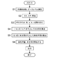
この実施例において、絶乾坪量及び水分量、さらに風乾坪量及び水分率まで求める動作を図14に示す。
定数A,B,a,b,cを決定するための標準サンプルを測定したマイクロ波共振器を用い、サンプルがないときのマイクロ波共振器における共振周波数と共振ピークレベルを測定しておく。その同じマイクロ波共振器によりサンプルを配置して共振周波数と共振ピークレベルを測定する(ステップS1)。
サンプル有無に関する共振周波数シフト量Δfrと共振ピークレベル変化量ΔPrを求める(ステップS2)。
メモリの定数記憶部114から定数A,B,a,b,cを取り込み、上記(1A)式と(2)式に代入する。(ステップS3)。
(1A)式に、ΔPとしてのΔPrを代入して水分量WTを算出する(ステップS4)。
(2)式に、ΔfとしてのΔfrと、ステップS4で算出したWTを代入して絶乾坪量BDを算出する(ステップS5)。
さらに上記(7)、(8)式を用いて風乾坪量及び水分率を算出する(ステップS6)。
(測定例1)
複数のサンプルについて、実際の抄紙機において本発明の実施例の装置により水分量を求めた結果を図15の縦軸に示し、同サンプルについてBM計により水分量を測定した結果を図15の横軸に示した。両水分量を一次関数で近似すると決定係数R2が0.9897という高い値をもつ。このことから、本発明により水分量を高精度に測定できることがわかる。
複数のサンプルについて、実際の抄紙機において本発明の実施例の装置により水分量を求めた結果を図15の縦軸に示し、同サンプルについてBM計により水分量を測定した結果を図15の横軸に示した。両水分量を一次関数で近似すると決定係数R2が0.9897という高い値をもつ。このことから、本発明により水分量を高精度に測定できることがわかる。
(測定例2)
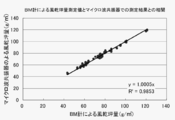
複数のサンプルについて、実際の抄紙機において本発明の実施例の装置により絶乾坪量を求めた結果を図16の縦軸に示し、同サンプルについてBM計により絶乾坪量を測定した結果を図16の横軸に示した。両絶乾坪量を一次関数で近似すると決定係数R2が0.9829という高い値をもつ。このことから、本発明により絶乾坪量を高精度に測定できることがわかる。
複数のサンプルについて、実際の抄紙機において本発明の実施例の装置により絶乾坪量を求めた結果を図16の縦軸に示し、同サンプルについてBM計により絶乾坪量を測定した結果を図16の横軸に示した。両絶乾坪量を一次関数で近似すると決定係数R2が0.9829という高い値をもつ。このことから、本発明により絶乾坪量を高精度に測定できることがわかる。
(測定例3)
複数のサンプルについて、実際の抄紙機において本発明の実施例の装置により風乾坪量を求めた結果を図17の縦軸に示し、同サンプルについてBM計により風乾坪量を測定した結果を図17の横軸に示した。両風乾坪量を一次関数で近似すると決定係数R2が0.9853という高い値をもつ。このことから、本発明により風乾坪量を高精度に測定できることがわかる。
複数のサンプルについて、実際の抄紙機において本発明の実施例の装置により風乾坪量を求めた結果を図17の縦軸に示し、同サンプルについてBM計により風乾坪量を測定した結果を図17の横軸に示した。両風乾坪量を一次関数で近似すると決定係数R2が0.9853という高い値をもつ。このことから、本発明により風乾坪量を高精度に測定できることがわかる。
1,1a~1e 誘電体共振器
2a,2b アンテナ
6 エバネセント波
8 サンプル
27 パーソナルコンピュータ
100 マイクロ波共振器
102 マイクロ波用励振装置
104 検出装置
106 データ処理装置
108 Δf・ΔP算出部
110 絶乾坪量・水分測定装置
112 定数/検量線決定部
114 定数/検量線記憶部
120 絶乾坪量・水分量算出部
122 風乾坪量・水分率算出部
2a,2b アンテナ
6 エバネセント波
8 サンプル
27 パーソナルコンピュータ
100 マイクロ波共振器
102 マイクロ波用励振装置
104 検出装置
106 データ処理装置
108 Δf・ΔP算出部
110 絶乾坪量・水分測定装置
112 定数/検量線決定部
114 定数/検量線記憶部
120 絶乾坪量・水分量算出部
122 風乾坪量・水分率算出部
Claims (8)
- (ステップS1)サンプルを設置しない第1の状態でのマイクロ波共振器における共振周波数f1、共振ピークレベルP1と、サンプルを設置した第2の状態での前記マイクロ波共振器における共振周波数f2、共振ピークレベルP2を測定し、共振周波数シフト量Δf(=f1-f2)とピークレベル変化量ΔP(=P1-P2)を求めるステップ、
(ステップS2)ΔPと水分量WTとの関係を示す検量線(1)
WT=F(ΔP) (1)
(F(ΔP)はΔPの関数)
を用い、ステップS1で求めたΔPから前記サンプルの水分量WTを求めるステップ、及び
(ステップS3)Δf、WT及びBDの関係を示す以下の式(2)
Δf=A・BD+B・WT (2)
(AとBは定数である。)
を用いて、ステップS1で求めたΔfとステップS2で求めたWTとから前記サンプルの絶乾坪量BDを求めるステップ、を含む坪量・水分量測定方法であって、
前記検量線(1)を決定するためのWTと、前記定数A、Bを決定するためのBDとWTは、複数の標準サンプルについてマイクロ波共振器以外の装置を用いて、又はマイクロ波共振器もマイクロ波共振器以外の前記装置も用いない方法により別途取得し、
前記検量線(1)は、別途取得したWTと該当する標準サンプルについて前記マイクロ波共振器を用いて得られた測定値ΔPとから求め、
前記定数A、Bは、別途取得したBDとWTを前記(2)式に当てはめて得られたΔfが、該当する標準サンプルについて前記マイクロ波共振器を用いて得られた測定値Δfに最も近くなるような定数A、Bの組み合わせとして求める坪量・水分量測定方法。 - 前記検量線(1)は、以下の近似式
WT=a・ΔP3+b・ΔP2+c・ΔP (1A)
に当てはめて定数a、b、cを決定することにより求める請求項1に記載の坪量・水分量測定方法。 - さらに、以下の式を用いて、風乾坪量及び水分率まで求める請求項1又は2に記載の坪量・水分量測定方法。
風乾坪量=絶乾坪量BD+水分量WT
水分率=水分量WT×100/風乾坪量 - 前記マイクロ波共振器としてサンプルの一面側のみに配置される複数個の矩形誘電体共振器を、それらの共振器の長辺方向がそれぞれ異なる方向(θ)を向くように同一平面上に配置し、
前記方向(θ)を角度θとしそれらの共振器の共振周波数シフト量Δf1~Δfnをrとして、角度をθ、原点からの距離をrとする極座標(r,θ)上にプロットし、楕円近似処理により楕円を描き、その楕円の面積と同面積の円の半径Δfrを求めて、そのΔfrを請求項1中のΔfとし、
それらの共振器のピークレベル変化量ΔP1~ΔPnを求め、次の(A)から(C)のいずれかのΔPrを請求項1中のΔPとする請求項1から3のいずれか一項に記載の坪量・水分量測定方法。
(A)ΔP1~ΔPnのいずれかからなるΔPr。
(B)ΔP1~ΔPnの平均値からなるΔPr。
(C)前記方向(θ)を角度θとしΔP1~ΔPnをrとして、角度をθ、原点からの距離をrとする極座標(r,θ)上にプロットし、楕円近似処理により楕円を描き、その楕円の面積と同面積の円の半径として求めたΔPr。 - マイクロ波共振器(100)と、
前記共振器(100)に電界ベクトルを発生させるマイクロ波用励振装置(102)と、
前記共振器(100)による透過エネルギー又は反射エネルギーを検出する検出装置(104)と、
前記検出装置(104)からサンプルを設置しない第1の状態での前記マイクロ波共振器(100)の共振周波数f1とその共振周波数f1位置でのピークレベルP1と、サンプルを設置した第2の状態での前記マイクロ波共振器(100)の共振周波数f2とその共振周波数f2位置でのピークレベルP2を取り込み、前記サンプルの絶乾坪量と水分量を算出するデータ処理装置(106)とを備えており、
前記データ処理装置(106)は、
前記検出装置(104)から取り込んだ前記共振周波数f1,f2と前記ピークレベルP1,P2から共振周波数シフト量Δf(=f1-f2)とピークレベル変化量ΔP(=P1-P2)を算出するΔf・ΔP算出部(108)と、
複数の標準サンプルについて別途取得した水分量WTと該当する標準サンプルについて前記Δf・ΔP算出部(108)で算出されたΔPとからΔPと水分量WTとの関係を示す検量線を求め、複数の標準サンプルについて別途取得した絶乾坪量BDとWTをΔf、WT及びBDの関係を示す以下の式(2)
Δf=A・BD+B・WT (2)
に当てはめて得られたΔfが、該当する標準サンプルについて前記Δf・ΔP算出部(108)で算出されたΔfに最も近くなるような定数A,Bの組み合わせを求める定数/検量線決定部(112)と、
前記定数/検量線決定部(112)で決定された定数A,Bと検量線を保持する定数/検量線記憶部(114)と、
前記Δf・ΔP算出部(108)で算出されたΔPを前記定数/検量線記憶部(114)に保持されている検量線に当てはめて前記サンプルの水分量WTを求め、そのように求められたWT、前記Δf・ΔP算出部(108)で算出されたΔf及び前記定数/検量線記憶部(114)に保持されている定数A,Bを前記式(2)に当てはめて前記サンプルの絶乾坪量を求める絶乾坪量・水分量算出部(120)と、
を備えている坪量・水分量測定装置。 - 前記定数/検量線決定部(112)は、前記検量線を以下の近似式
WT=a・ΔP3+b・ΔP2+c・ΔP (1A)
に当てはめて定数a、b、cを決定するものであり、
前記定数/検量線記憶部(114)は前記検量線に相当するものとして前記定数/検量線決定部(112)が決定した前記定数a、b、cを記憶するものであり、
前記絶乾坪量・水分量算出部(120)は前記定数/検量線記憶部(114)に保持されている前記定数a、b、cを前記(1A)式に当てはめたものを検量線として用いて水分量WTを求めるものである請求項5に記載の坪量・水分量測定装置。 - 前記データ処理装置(106)は、以下の式を用いて、風乾坪量と水分率を求める風乾坪量・水分率算出部(122)をさらに備えている請求項5又は6に記載の坪量・水分量測定装置。
風乾坪量=絶乾坪量BD+水分量WT
水分率=水分量WT×100/風乾坪量 - 前記マイクロ波共振器(100)はサンプルの一面側のみに配置される複数個の矩形誘電体共振器であって、それらの共振器の長辺方向がそれぞれ異なる方向(θ)を向くように同一平面上に配置されたものであり、
前記Δf・ΔP算出部(108)は請求項4に記載されたΔfrとΔPrを算出するものであり、
前記絶乾坪量・水分量算出部(120)は前記Δf・ΔP算出部(108)により算出されたΔfrとΔPrを用いて演算を行うものである請求項5から7のいずれか一項に記載の坪量・水分量測定装置。
Priority Applications (1)
| Application Number | Priority Date | Filing Date | Title |
|---|---|---|---|
| JP2015544915A JP6176332B2 (ja) | 2013-10-31 | 2014-10-16 | 坪量及び水分量の測定方法と装置 |
Applications Claiming Priority (2)
| Application Number | Priority Date | Filing Date | Title |
|---|---|---|---|
| JP2013-226178 | 2013-10-31 | ||
| JP2013226178 | 2013-10-31 |
Publications (1)
| Publication Number | Publication Date |
|---|---|
| WO2015064370A1 true WO2015064370A1 (ja) | 2015-05-07 |
Family
ID=53003979
Family Applications (1)
| Application Number | Title | Priority Date | Filing Date |
|---|---|---|---|
| PCT/JP2014/077541 Ceased WO2015064370A1 (ja) | 2013-10-31 | 2014-10-16 | 坪量及び水分量の測定方法と装置 |
Country Status (2)
| Country | Link |
|---|---|
| JP (1) | JP6176332B2 (ja) |
| WO (1) | WO2015064370A1 (ja) |
Cited By (4)
| Publication number | Priority date | Publication date | Assignee | Title |
|---|---|---|---|---|
| JPWO2022114206A1 (ja) * | 2020-11-30 | 2022-06-02 | ||
| JP2023547079A (ja) * | 2020-11-03 | 2023-11-09 | テウス エレクトロニク ゲーエムベーハー ウント コー カーゲー | 測定装置を較正する方法 |
| WO2023218766A1 (ja) * | 2022-05-13 | 2023-11-16 | ソニーグループ株式会社 | センサ装置、情報処理装置、情報処理方法、及びプログラム |
| CN119198786A (zh) * | 2024-09-30 | 2024-12-27 | 湖北中烟工业有限责任公司 | 加热不燃烧薄片中雾化剂含量的测量方法、系统及介质 |
Citations (4)
| Publication number | Priority date | Publication date | Assignee | Title |
|---|---|---|---|---|
| JPS5830534B2 (ja) * | 1978-02-27 | 1983-06-29 | 株式会社日本特殊計測器製作所 | シ−ト状物体の含水率、坪量測定装置 |
| JP2006349425A (ja) * | 2005-06-14 | 2006-12-28 | Oji Paper Co Ltd | 坪量測定方法及び装置 |
| JP2010101789A (ja) * | 2008-10-24 | 2010-05-06 | Oji Paper Co Ltd | 坪量測定方法及び装置 |
| WO2011092889A1 (ja) * | 2010-01-28 | 2011-08-04 | 王子製紙株式会社 | 坪量及び水分量の測定方法と装置 |
-
2014
- 2014-10-16 WO PCT/JP2014/077541 patent/WO2015064370A1/ja not_active Ceased
- 2014-10-16 JP JP2015544915A patent/JP6176332B2/ja not_active Expired - Fee Related
Patent Citations (4)
| Publication number | Priority date | Publication date | Assignee | Title |
|---|---|---|---|---|
| JPS5830534B2 (ja) * | 1978-02-27 | 1983-06-29 | 株式会社日本特殊計測器製作所 | シ−ト状物体の含水率、坪量測定装置 |
| JP2006349425A (ja) * | 2005-06-14 | 2006-12-28 | Oji Paper Co Ltd | 坪量測定方法及び装置 |
| JP2010101789A (ja) * | 2008-10-24 | 2010-05-06 | Oji Paper Co Ltd | 坪量測定方法及び装置 |
| WO2011092889A1 (ja) * | 2010-01-28 | 2011-08-04 | 王子製紙株式会社 | 坪量及び水分量の測定方法と装置 |
Cited By (6)
| Publication number | Priority date | Publication date | Assignee | Title |
|---|---|---|---|---|
| JP2023547079A (ja) * | 2020-11-03 | 2023-11-09 | テウス エレクトロニク ゲーエムベーハー ウント コー カーゲー | 測定装置を較正する方法 |
| JP7559234B2 (ja) | 2020-11-03 | 2024-10-01 | テウス エレクトロニク ゲーエムベーハー ウント コー カーゲー | 測定装置を較正する方法 |
| JPWO2022114206A1 (ja) * | 2020-11-30 | 2022-06-02 | ||
| WO2022114206A1 (ja) * | 2020-11-30 | 2022-06-02 | マイクロ波化学株式会社 | 状態検出装置、状態検出方法及びプログラム |
| WO2023218766A1 (ja) * | 2022-05-13 | 2023-11-16 | ソニーグループ株式会社 | センサ装置、情報処理装置、情報処理方法、及びプログラム |
| CN119198786A (zh) * | 2024-09-30 | 2024-12-27 | 湖北中烟工业有限责任公司 | 加热不燃烧薄片中雾化剂含量的测量方法、系统及介质 |
Also Published As
| Publication number | Publication date |
|---|---|
| JP6176332B2 (ja) | 2017-08-09 |
| JPWO2015064370A1 (ja) | 2017-03-09 |
Similar Documents
| Publication | Publication Date | Title |
|---|---|---|
| JP5541294B2 (ja) | 坪量及び水分量の測定方法と装置 | |
| EP1734361B1 (en) | Method and device for measuring grammage (basis weight, mass per unit area) and moisture of a sheet, for example of paper, using dielectric resonators | |
| JP6176332B2 (ja) | 坪量及び水分量の測定方法と装置 | |
| CN101398378B (zh) | 一种表面等离子共振的相位测量方法及其测量系统 | |
| JPH02248846A (ja) | 製品の湿度を測定する方法とその装置 | |
| CN103712639B (zh) | 一种光纤布里渊散射频谱的分布式快速检测方法和装置 | |
| US20170138801A1 (en) | Method for measuring internal temperature of freezing target object and internal temperature measurement device for freezing target object | |
| JPH03128446A (ja) | 散乱電磁放射線を用いて物体の特性を測定する装置および方法 | |
| US20110169507A1 (en) | Methods and apparatus for the determination of moisture content | |
| JP5169733B2 (ja) | 坪量測定方法及び装置 | |
| Holloway et al. | Atom-based RF electric field measurements: an initial investigation of the measurement uncertainties | |
| JP2009058379A (ja) | 水分量および塗工量の測定方法 | |
| EP2228640B1 (en) | Method for determining the moisture content of wood | |
| JP2017207422A (ja) | 誘電率評価方法 | |
| US11828716B2 (en) | Method and device for determining the material moisture of a material | |
| CN112798875A (zh) | 毫米波与太赫兹波电场测量方法、装置及系统 | |
| Noskov | Analysis of the impact of noise on the characteristics of autodyne sensors of vibrations and small displacements | |
| RU2626573C1 (ru) | Устройство бесконтактного измерения электромагнитных параметров тонких пленок | |
| Antikainen et al. | Comparison of the accuracy of two on-line industrial veneer moisture content and density measurement systems | |
| JP2022155003A (ja) | 測定装置及び測定方法 | |
| JP2020148713A (ja) | 解析装置、方法及びプログラム | |
| JP6457408B2 (ja) | イメージング方法 | |
| CN121977460A (en) | Device and method for improving film thickness measurement precision | |
| Holloway et al. | Development of a new atom-based SI traceable electric-field metrology technique | |
| FI20206141A1 (en) | A device and a method for fluid measuring device |
Legal Events
| Date | Code | Title | Description |
|---|---|---|---|
| 121 | Ep: the epo has been informed by wipo that ep was designated in this application |
Ref document number: 14859019 Country of ref document: EP Kind code of ref document: A1 |
|
| ENP | Entry into the national phase |
Ref document number: 2015544915 Country of ref document: JP Kind code of ref document: A |
|
| NENP | Non-entry into the national phase |
Ref country code: DE |
|
| 122 | Ep: pct application non-entry in european phase |
Ref document number: 14859019 Country of ref document: EP Kind code of ref document: A1 |