WO2015064274A1 - 撮像素子 - Google Patents
撮像素子 Download PDFInfo
- Publication number
- WO2015064274A1 WO2015064274A1 PCT/JP2014/076032 JP2014076032W WO2015064274A1 WO 2015064274 A1 WO2015064274 A1 WO 2015064274A1 JP 2014076032 W JP2014076032 W JP 2014076032W WO 2015064274 A1 WO2015064274 A1 WO 2015064274A1
- Authority
- WO
- WIPO (PCT)
- Prior art keywords
- light
- pixels
- color
- substrate
- color filter
- Prior art date
- Legal status (The legal status is an assumption and is not a legal conclusion. Google has not performed a legal analysis and makes no representation as to the accuracy of the status listed.)
- Ceased
Links
Images







Classifications
-
- G—PHYSICS
- G02—OPTICS
- G02B—OPTICAL ELEMENTS, SYSTEMS OR APPARATUS
- G02B5/00—Optical elements other than lenses
- G02B5/20—Filters
- G02B5/201—Filters in the form of arrays
-
- H—ELECTRICITY
- H04—ELECTRIC COMMUNICATION TECHNIQUE
- H04N—PICTORIAL COMMUNICATION, e.g. TELEVISION
- H04N23/00—Cameras or camera modules comprising electronic image sensors; Control thereof
- H04N23/10—Cameras or camera modules comprising electronic image sensors; Control thereof for generating image signals from different wavelengths
- H04N23/12—Cameras or camera modules comprising electronic image sensors; Control thereof for generating image signals from different wavelengths with one sensor only
-
- H—ELECTRICITY
- H04—ELECTRIC COMMUNICATION TECHNIQUE
- H04N—PICTORIAL COMMUNICATION, e.g. TELEVISION
- H04N23/00—Cameras or camera modules comprising electronic image sensors; Control thereof
- H04N23/80—Camera processing pipelines; Components thereof
- H04N23/84—Camera processing pipelines; Components thereof for processing colour signals
- H04N23/843—Demosaicing, e.g. interpolating colour pixel values
-
- H—ELECTRICITY
- H04—ELECTRIC COMMUNICATION TECHNIQUE
- H04N—PICTORIAL COMMUNICATION, e.g. TELEVISION
- H04N25/00—Circuitry of solid-state image sensors [SSIS]; Control thereof
- H04N25/10—Circuitry of solid-state image sensors [SSIS]; Control thereof for transforming different wavelengths into image signals
- H04N25/11—Arrangement of colour filter arrays [CFA]; Filter mosaics
- H04N25/13—Arrangement of colour filter arrays [CFA]; Filter mosaics characterised by the spectral characteristics of the filter elements
- H04N25/134—Arrangement of colour filter arrays [CFA]; Filter mosaics characterised by the spectral characteristics of the filter elements based on three different wavelength filter elements
-
- H—ELECTRICITY
- H10—SEMICONDUCTOR DEVICES; ELECTRIC SOLID-STATE DEVICES NOT OTHERWISE PROVIDED FOR
- H10F—INORGANIC SEMICONDUCTOR DEVICES SENSITIVE TO INFRARED RADIATION, LIGHT, ELECTROMAGNETIC RADIATION OF SHORTER WAVELENGTH OR CORPUSCULAR RADIATION
- H10F39/00—Integrated devices, or assemblies of multiple devices, comprising at least one element covered by group H10F30/00, e.g. radiation detectors comprising photodiode arrays
- H10F39/80—Constructional details of image sensors
- H10F39/805—Coatings
- H10F39/8053—Colour filters
Definitions
- the present invention relates to an image sensor.
- This application claims priority based on Japanese Patent Application No. 2013-226260 filed in Japan on October 31, 2013, the contents of which are incorporated herein by reference.
- a single-plate image pickup device constituted by light receiving elements arranged two-dimensionally is employed.
- a color filter is disposed in front of the light receiving element in order to obtain a full color image.
- types of the color filter there are an RGB primary color system and a CMYG complementary color system.
- FIG. 13 is a schematic diagram showing a color arrangement of a color filter of a primary color system known as a Bayer arrangement that is conventionally known.
- a color filter R that transmits red (R) light
- a color filter G that transmits green (G) light
- a color filter B that transmits blue (B) light
- the color filter G occupies 1/2 of the total number of pixels.
- the color filter R occupies 1/4 of the total number of pixels.
- the color filter B occupies 1/4 of the total number of pixels.
- each pixel has red, green, and blue colors.
- the color information of two colors is always missing. Therefore, the missing color information of the two colors is interpolated based on the output of the adjacent pixel, and the demosaicing process is performed so that each pixel obtains color information of three colors of red, blue, and green.
- the following two methods are generally known as demosaicing processing.
- the first method is a method of linear interpolation from adjacent or neighboring pixels.
- the second method is a method of calculating a color difference signal after linear interpolation, determining whether the correlation is strong in the vertical direction or the horizontal direction, and further performing interpolation processing according to the result. For example, if the correlation is high in the vertical direction, further interpolation is performed with the average value of pixels adjacent in the vertical direction.
- FIG. 14 is a schematic diagram showing a color arrangement of a complementary color filter called a conventionally known color difference sequential method.
- a color filter C that transmits cyan (C) light
- a color filter M that transmits magenta (M) light
- a color filter Y that transmits yellow light (Y)
- green Color filters G that transmit light (G) are regularly arranged on the light receiving surface of each pixel.
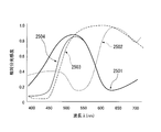
- FIG. 15 is a graph showing the transmission characteristics of the conventionally known color filter C, color filter M, color filter Y, and color filter G.
- the horizontal axis of the graph indicates the wavelength ⁇ (nm).
- the vertical axis of the graph represents relative spectral sensitivity.
- a curve 2501 indicates the transmission characteristics of the color filter C.
- a curve 2502 indicates the transmission characteristic of the color filter M.
- a curve 2503 indicates the transmission characteristics of the color filter Y.
- a curve 2504 shows the transmission characteristics of the color filter G.
- each pixel has a cyan color.
- the color information of three colors of magenta, yellow, and green is always missing.
- conversion is performed by the following method (for example, see Patent Document 1).
- the color information of all CMYG is calculated for each pixel by using the color information of CMYG acquired by each pixel. As a calculation method, linear interpolation or the like is performed.
- CMYG color information is converted into RGB color information.
- the transmittance of each RGB color component transmitted by each color filter of CMYG is a parameter determined by the transmission characteristics of CMYG at the time of manufacture.
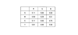
- FIG. 16 is a schematic diagram showing an example of the transmittance of each RGB color component that is transmitted through each conventionally known CMYG color filter.
- the color filter G has a red light transmittance of 0.11. Further, the transmittance of green light of the color filter G is 0.86. The blue light transmittance of the color filter G is 0.08.
- the color filter M has a red light transmittance of 0.50. Further, the transmittance of green light of the color filter M is 0.29. The blue light transmittance of the color filter M is 0.51.
- the color filter C has a red light transmittance of 0.11. Further, the transmittance of green light of the color filter C is 0.92. The blue light transmittance of the color filter C is 0.75.
- the red light transmittance of the color filter Y is 0.81. Further, the transmittance of green light of the color filter Y is 0.98.
- the blue light transmittance of the color filter Y is 0.08.
- the present invention has been made to solve the above-described problems, and an object of the present invention is to provide an imaging device capable of increasing the accuracy of sensitivity and color reproducibility.
- the imaging device includes a first substrate and a plurality of first light receiving elements that are regularly arranged on the first substrate and that output a first signal corresponding to the intensity of the irradiated light.
- a plurality of first color filters disposed on each of the light receiving surfaces of the first light receiving element and transmitting light in a first wavelength band including at least a second wavelength band and a third wavelength band;
- a second substrate disposed so as to be irradiated with light transmitted through one substrate, and a plurality of second substrates regularly disposed on the second substrate and outputting a second signal corresponding to the intensity of the irradiated light.
- Two light receiving elements a plurality of second color filters disposed on each of the light receiving surfaces of the second light receiving element and transmitting light in the second wavelength band, the first signal, and the second signal.
- the first wavelength band is a wavelength band of light of magenta (M) in a CMY complementary color system with respect to an RGB color system.
- the third wavelength band is a wavelength band of blue (B) light in the RGB color system, and the first wavelength band is yellow (Y) in a CMY complementary color system with respect to the RGB color system.
- the third wavelength band is a wavelength band of green (G) light in the RGB color system, and the second wavelength band is red (in the RGB color system).
- R may be the wavelength band of light.
- a plurality of signals that are regularly arranged on the first substrate and output a third signal corresponding to the intensity of the irradiated light.
- a third light receiving element, a plurality of third color filters disposed on each of the light receiving surfaces of the third light receiving element and transmitting light in a fourth wavelength band including at least a fifth wavelength band; and the second substrate.
- a plurality of fourth light receiving elements that are regularly arranged and output a fourth signal corresponding to the intensity of the irradiated light, and are arranged on each of the light receiving surfaces of the fourth light receiving elements, and are light in the fifth wavelength band.
- a plurality of fourth color filters that transmit light, and the signal processing unit uses the third signal and the fourth signal to correspond to each of the plurality of third light receiving elements.
- a signal may be generated.
- the fourth wavelength band is a wavelength band of cyan (C) light or yellow in a CMY complementary color system with respect to the RGB color system.
- (Y) wavelength band of light and the fifth wavelength band may be a wavelength band of green (G) light in the RGB color system.
- the fourth wavelength band may be equal to the fifth wavelength band.
- the light receiving area of the light receiving surface of the second light receiving element is larger than the light receiving area of the light receiving surface of the first light receiving element. Also good.
- Each of the plurality of second light receiving elements may be arranged to have a one-to-one correspondence with the plurality of first light receiving elements.
- the imaging device includes a first substrate, a plurality of first light receiving elements, a plurality of first color filters, a second substrate, a plurality of second light receiving elements, and a plurality of second color filters.
- the plurality of first light receiving elements are regularly arranged on the first substrate and output a first signal corresponding to the intensity of the irradiated light.
- the plurality of first color filters are disposed on each of the light receiving surfaces of the first light receiving element and transmit light in the first wavelength band including at least the second wavelength band and the third wavelength band.
- the second substrate is arranged so that light transmitted through the first substrate is irradiated.
- the plurality of second light receiving elements are regularly arranged on the second substrate and output a second signal corresponding to the intensity of the irradiated light.
- the plurality of second color filters are disposed on each of the light receiving surfaces of the second light receiving element and transmit light in the second wavelength band.
- the signal processing unit generates a pixel signal corresponding to each of the plurality of first light receiving elements using the first signal and the second signal.
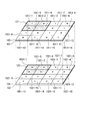
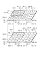
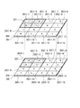
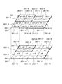
- FIG. 3 is a schematic diagram illustrating an arrangement of complementary color filters and an arrangement of primary color filters in the first embodiment of the present invention. It is the schematic which showed the 1st signal which the 1st pixel in the 1st Embodiment of this invention outputs, and the 2nd signal which a 2nd pixel outputs. In the 1st Embodiment of this invention, it is the schematic which showed the result of having calculated the 1st step. It is the schematic which showed the arrangement
- FIG. 6 is a graph showing transmission characteristics of a conventionally known color filter C, color filter M, color filter Y, and color filter G. It is the schematic which showed an example of the transmittance
- FIG. 1 is a cross-sectional view illustrating a cross section of an image sensor 100 according to the present embodiment.
- the image sensor 100 includes a first substrate 101 (first substrate), a second substrate 102 (second substrate), a complementary color filter 103, a primary color filter 104, A connection unit 105 and a signal processing unit 106 are provided.
- the first substrate 101 is formed on a silicon chip and includes a plurality of first pixels.
- the second substrate 102 is formed on a silicon chip and includes a plurality of second pixels.
- the complementary color filter 103 is a CMY complementary color filter for the RGB color system.
- the plurality of first pixels included in the first substrate 101 includes a photoelectric conversion element (first light receiving element) and a signal readout circuit.
- the plurality of second pixels included in the second substrate 102 includes a photoelectric conversion element (second light receiving element) and a signal readout circuit.
- the photoelectric conversion element outputs a signal charge corresponding to the exposure amount to the readout circuit.
- the signal readout circuit outputs the signal charge as an electric signal.
- a complementary color filter 103 is formed on the light receiving surface side of the first substrate 101. The arrangement of the complementary color filter 103 will be described later.
- a primary color filter 104 is formed on the light receiving surface side of the second substrate 102. The arrangement of the primary color filters 104 will be described later.
- the first substrate 101 and the second substrate 102 are stacked.
- the second substrate 102 is disposed on the side opposite to the light receiving surface of the first substrate 101.
- the light receiving surface of the second substrate 102 is the side on which the first substrate 101 exists.
- a connection portion 105 is configured between the first substrate 101 and the second substrate 102, and the first substrate 101 and the second substrate 102 are electrically connected via the connection portion 105. Has been. That is, the first substrate 101 and the second substrate 102 are bonded to each other through the connection portion 105.
- Each of the first pixels included in the first substrate 101 acquires a first signal.
- Each of the second pixels included in the second substrate 102 acquires a second signal.
- the first signal acquired by the first substrate 101 and the second signal acquired by the second substrate 102 are output to the signal processing unit 106 via the connection unit 105.
- the signal processing unit 106 may be provided on either the first substrate 101 or the second substrate 102, or may be provided on other than the first substrate 101 and the second substrate 102.
- the signal processing unit 106 generates a pixel signal for each of the first pixels using the first signal and the second signal. That is, the signal processing unit 106 generates a full-color image having RGB (red, green, blue) color information.
- the first substrate 101 is a back-illuminated imaging substrate, and the thickness of the first substrate 101 is about several um and is thin. Therefore, a part of the light incident from the light receiving surface side of the first substrate 101 is transmitted and enters the light receiving surface side of the second substrate 102.
- the absorption factor with respect to the light for every depth of silicon changes with wavelengths. In the shallow part of silicon, the absorption rate of light having a short wavelength is high, and the absorption rate of light having a long wavelength is low. That is, the first substrate 101 having a small thickness absorbs light having a short wavelength but does not absorb light having a long wavelength.
- the thickness of the first substrate 101 is about 3 ⁇ m.
- the second substrate 102 is a front-illuminated imaging substrate and is thicker than the first substrate 101. For this purpose, the second substrate 102 detects the transmitted light transmitted through the first substrate 101.
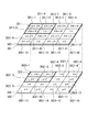
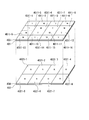
- FIG. 2 is a schematic view showing the arrangement of the complementary color filter 103 and the arrangement of the primary color filter 104 in the present embodiment.
- the first substrate 101 has a total of 16 first pixels 1011-1 to 1011-16 (first light receiving elements) regularly arranged in a two-dimensional manner of 4 rows and 4 columns. )It is included.
- the second substrate 102 includes a total of 16 second pixels 1021-1 to 1021-16 (second light receiving elements) regularly arranged in a two-dimensional manner of 4 rows and 4 columns. Yes. Note that the number and arrangement of the first pixels 1011 included in the first substrate 101 and the second pixels 1021 included in the second substrate 102 are not limited to the illustrated example, and may be any number and arrangement. .
- Y is a filter in which a plurality of color filters (first color filters) are arranged.
- the first pixels 1011-1, 1011-3, 1011-6, 1011-8, 1011-9, 1011-11, 1011-14, and 1011-16 have a color filter Y that transmits yellow (Y) light. Is formed.
- the first pixels 1011-2, 1011-4, 1011-5, 1011-7, 1011-10, 1011-12, 1011-13, and 1011-15 have a color filter M that transmits magenta (M) light. Is formed.
- first pixels 1011 adjacent in the vertical and horizontal directions are defined as a set of unit pixel regions 121.
- a set of unit pixel areas 121 includes two first pixels 1011-2 and 1011-5 on which a color filter M that transmits magenta light is formed, and a color filter Y that transmits yellow light. It is composed of two formed first pixels 1011-1 and 1011-6.
- the primary color filter 104 formed on the second substrate 102 is a filter in which a plurality of color filters R (second color filters) that transmit red (R) light are arranged.
- a color filter R that transmits red (R) light is formed in the second pixels 1021-1 to 1021-16.
- one set of unit pixel region 122 includes four pixels 1021-1, 1021-2, 1021-5, and 1021-6 on which a color filter R that transmits red light is formed.
- the first pixels 1011-1 to 1011-16 included in the first substrate 101 and the second pixels 1021-1 to 1021-16 included in the second substrate 102 have a one-to-one correspondence. They are arranged in a relationship. For example, the first pixel 1011-1 and the second pixel 1021-1 are arranged so that the light transmitted through the first pixel 1011-1 is irradiated only to the corresponding second pixel 1021-1. Has been. In addition, the first pixel 1011-2 and the second pixel 1021-2 are arranged so that the light transmitted through the first pixel 1011-2 is irradiated only to the corresponding second pixel 1021-2. Has been. Similarly, the first pixels 1011-3 to 1011-16 and the second pixels 1021-3 to 1021-16 are arranged as illustrated.
- the first substrate 101 transmits light having a wavelength of 500 nm or more (high-wavelength light, red (R) light, and infrared (IR) light among green (G) light).
- Light is most easily transmitted through the first substrate 101.
- Light having a wavelength of 500 nm or more transmitted through the first substrate 101 is irradiated to the second substrate 102. Therefore, in this embodiment, as shown in FIG. 2, only the color filter R that transmits red (R) light is used as the primary color filter 104 formed on the second substrate 102.
- M magenta color
- Y yellow
- the first signal acquired by the first substrate 101 is the signal M corresponding to the intensity of magenta (M) light and the signal Y corresponding to the intensity of yellow (Y) light.
- the second signal acquired by the second substrate 102 is a signal R corresponding to the intensity of red (R) light.
- the signal processing unit 106 uses the first signal and the second signal to calculate the RGB color information of each first pixel 1011 with high accuracy. The details of a method for calculating RGB color information by the signal processing unit 106 will be described later.
- the image sensor 100 is irradiated with light from which infrared light has been cut by an infrared light (IR) cut filter.
- IR infrared light
- Each of the first pixels 1011-1 to 1011-16 detects the light transmitted through the complementary color filter 103 and outputs a first signal. Specifically, the first pixels 1011-1, 1011-3, 1011-6, 1011-8, 1011-9, 1011-11, 1011 in which the color filter Y that transmits yellow (Y) light is formed. ⁇ 14, 1011-16 output a first signal corresponding to the intensity of yellow (Y) light.
- each of the second pixels 1021-1 to 1021-16 of the second substrate 102 detects light transmitted through the complementary color filter 103, the first substrate 101, and the primary color filter 104.
- the second signal is output.
- each of the second pixels 1021-1 to 1021-16 in which the color filter R that transmits red (R) light is formed has a second color corresponding to the intensity of the red (R) light. Output a signal.
- the first signal output from the first pixels 1011-1 to 1011-16 and the second signal output from the second pixels 1021-1 to 1021-16 are connected to the signal processing unit via the connection unit 105, respectively. It is output to 106.
- the signal processing unit 106 uses the first signal and the second signal to generate a full color image having RGB color information of each of the first pixels 1011-1 to 1011-16.
- FIG. 3 shows the first signal output from the first pixels 1011-1 to 1011-16 and the second signal output from the second pixels 1021-1 to 1021-16 in this embodiment.
- a unit pixel region 121 composed of first pixels 1011-1, 1011-2, 1011-5, 1011-6 is shown.
- a unit pixel region 122 including second pixels 1021-1, 1021-2, 1021-5, and 1021-6 is shown on the second substrate 102.
- yellow light (Y) is transmitted through the first pixels 1011-1, 1011-3, 1011-6, 1011-8, 1011-9, 1011-11, 1011-14, and 1011-16.
- a color filter Y is formed.
- the first signal output from the first pixels 1011-1, 1011-3, 1011-6, 1011-8, 1011-9, 1011-11, 1011-14, 1011-16 is ⁇ G + ⁇ R.
- G is a value corresponding to the intensity of green light.
- R is a value corresponding to the intensity of red light.
- the values of ⁇ and ⁇ are values determined at the time of manufacturing the color filter Y, and are fixed values.
- the first pixels 1011-2, 1011-4, 1011-5, 1011-7, 1011-10, 1011-12, 1011-13, and 1011-15 have magenta color (M).
- a color filter M that transmits light is formed.
- the first signal output from the first pixels 1011-2, 1011-4, 1011-5, 1011-7, 1011-10, 1011-12, 1011-13, and 1011-15 is ⁇ B + ⁇ R.
- B is a value corresponding to the intensity of blue light.
- R is a value corresponding to the intensity of red light.
- the values of ⁇ and ⁇ are values determined when the color filter M is manufactured, and are fixed values.
- the color filters R that transmit red (R) light are formed in the second pixels 1021-1 to 1021-16.
- the second pixels 1021-1, 1021-3, 1021-6, 1021-8, 1021-9, 1021-11, 1021-14, and 1021-16 include the first pixels 1011-1, 1011-3, 1011-6, 1011-8, 1011-9, 1011-11, 1011-14, 1011-16 are transmitted. That is, the second pixel 1021-1, 1021-3, 1021-6, 1021-8, 1021-9, 1021-11, 1021-14, 1021-16 includes the color filter Y and the first substrate 101. Then, light that has passed through the color filter R enters.
- the second signal output from the second pixels 1021-1, 1021-3, 1021-6, 1021-8, 1021-9, 1021-11, 1021-14, 1021-16 is ⁇ R.
- R is a value corresponding to the intensity of red light.
- the value of ⁇ is a value determined when the color filter R is manufactured, and is a fixed value.
- the first pixels 1011-2, 1011-4, 1011-5, 1011-7, 1011-10, 1011-12, 1011-13, 1011 on which the color filter Y is formed on the first substrate 101 are also illustrated.
- the ratio of ⁇ and ⁇ is a parameter determined at the time of manufacture.
- ⁇ is determined by the spectral characteristics of the first substrate 101 and the second substrate 102 determined based on the transmission characteristics of the color filter Y and the color filter R, the thicknesses of the first substrate 101 and the second substrate 102, and the like.
- the ratio with ⁇ is determined.
- the light transmitted through the first pixels 1011-2 and 1011-5 is incident on the second pixels 1021-2 and 1021-5. That is, light that has passed through the color filter M, the first substrate 101, and the color filter R is incident on the second pixels 1021-2 and 1021-5.
- the second signal output from the second pixels 1021-2 and 1021-5 is ⁇ R.
- R is a value corresponding to the intensity of red light.
- the value of ⁇ is a value determined when the color filter R is manufactured, and is a fixed value.
- the first pixels 1011-2, 1011-4, 1011-5, 1011-7, 1011-10, 1011-12, 1011-13, 1011 with the color filter M formed on the first substrate 101 are used.
- the ratio of ⁇ and ⁇ is a parameter determined at the time of manufacture. For example, depending on the transmission characteristics of the color filter M and the color filter R and the spectral sensitivity of the first substrate 101 and the second substrate 102 determined based on the thicknesses of the first substrate 101 and the second substrate 102, ⁇ and The ratio with ⁇ is determined.
- the signal processing unit 106 includes the first signal output from the first pixels 1011-1 to 1011-16 of the first substrate 101 and the second pixels 1021-1 to 1021-16 of the second substrate 102. RGB color information of each of the first pixels 1011-1 to 1011-16 is calculated using the second signal to be output.
- the signal processing unit 106 calculates the RGB color information of each of the first pixels 1011-1 to 1011-16 by executing the following two steps of the first step and the second step. To do.
- the signal processing unit 106 performs arithmetic processing using the first signal that has been transmitted through the complementary color filter 103 and the second signal that has been transmitted through the primary color filter 104.
- the color information of two colors among the RGB color information is separated and calculated.
- Information is used to perform arithmetic processing using the second signal “ ⁇ R” output from the second pixel 1021-1 formed with “G” color information and “R” color in the first pixel 1011-1.
- the values of ⁇ , ⁇ , and ⁇ are known, and the ratio of ⁇ and ⁇ is also known. Therefore, among the first signals “ ⁇ G + ⁇ R” using the second signal “ ⁇ R”, “ ⁇ R "is calculated. As a result, pure “R” color information can be calculated. Subsequently, “ ⁇ G” is calculated by subtracting the calculated “ ⁇ R” from the first signal “ ⁇ G + ⁇ R”. As a result, pure “G” color information can be calculated. That is, pure “G” and “R” color information in the first pixel 1011-1 provided with the color filter Y can be calculated by the above-described calculation method. The same processing is performed for the first pixels 1011-1, 1011-3, 1011-6, 1011-8, 1011-9, 1011-11, 1011-14, and 1011-16, and pure “G” And “R” color information are calculated.
- Calculation processing is performed using the second signal “ ⁇ R” output from the second pixel 1021-2 in which the color filter R is formed, and the color information of “B” in the first pixel 1011-2 and the “R” ”Color information.
- the second signal “ ⁇ R” is used to select the first signal “ ⁇ B + ⁇ R” from “ ⁇ R ”is calculated.
- pure “R” color information can be calculated.
- “ ⁇ B” is calculated by subtracting the calculated “ ⁇ R” from the first signal “ ⁇ B + ⁇ R”.
- pure “B” color information can be calculated.
- pure “B” color information and “R” color information in the first pixel 1011-2 provided with the color filter M can be calculated by the above-described calculation method.
- the same processing is performed for the first pixels 1011-2, 1011-4, 1011-5, 1011-7, 1011-10, 1011-12, 1011-13, and 1011-15, and pure “B” And the color information of “R” are calculated.
- FIG. 4 is a schematic diagram showing the result of the calculation of the first step in the present embodiment.
- “,” indicates that the first pixel 1011-1 to 1011-16 in which the complementary color system color filter 103 is arranged separately calculates the color information of two colors out of the RGB color information. ing.
- the first pixels 1011-1, 1011-3, 1011-6, 1011-8, 1011-9, 1011 on which the color filter Y is formed are formed.
- the color information of “ ⁇ G, ⁇ R” can be obtained at ⁇ 11, 1011-14, 1011-16, respectively.
- the color information obtained by the second pixels 1021-1, 1021-3, 1021-6, 1021-8, 1021-9, 1021-11, 1021-14, and 1021-16 is “ ⁇ R”. Is.
- the first pixels 1011-2, 1011-4, 1011-5, 1011-7, and 1011-10 on which the color filter M is formed are formed.
- the color information of “ ⁇ B, ⁇ R” can be obtained respectively.
- the color information obtained by the second pixels 1021-2, 1021-4, 1021-5, 1021-7, 1021-10, 1021-12, 1021-13, and 1021-15 is “ ⁇ R Is.
- ⁇ Second step> In the second step, in each of the first pixels 1011-1 to 1011-16, the color information of the remaining one color is calculated using the color information of the two colors calculated in the first step.
- the color information of the remaining one color is subjected to linear interpolation or the like using the color information of the first pixels 1011-1 to 1011-16 arranged adjacent to or in the vicinity as in the conventionally known demosaicing process. ,calculate.
- the first pixels 1011-1, 1011-2, 1011-3, 1011-5, 1011-7, 1011-9, 1011-10, 1011-11 adjacent to the first pixel 1011-6 are When attention is paid, color information “B” is obtained in the first pixels 1011-2, 1011-5, 1011-7, and 1011-10.
- the signal processing unit 106 performs an interpolation process using the color information of “B” of the four first pixels 1011-2, 1011-5, 1011-7, 1011-10, and performs the first pixel 1011-6.
- the color information of “B” is calculated.
- the signal processing unit 106 calculates the missing color information using linear interpolation or the like, as in the conventional primary color demosaicing process.
- the same processing is performed for the first pixels 1011-1, 1011-3, 1011-8, 1011-9, 1011-11, 1011-14, and 1011-16, and “B” color information is calculated. To do.
- the color information of “G” is lacking.
- the first pixels 1011-5, 1011-6, 1011-7, 1011-9, 1011-11, 1011-13, 1011-14, 1011-15 adjacent to the first pixel 1011-10 When attention is paid, color information of “G” is obtained in the first pixels 1011-6, 1011-9, 1011-11 and 1011-14.
- the signal processing unit 106 performs an interpolation process using the “G” color information of the four first pixels 1011-6, 1011-9, 1011-11, and 1011-14, and the first pixel 1011-10
- the color information of “G” at is calculated.
- the signal processing unit 106 calculates the missing color information using linear interpolation or the like, as in the conventional primary color demosaicing process.
- the same processing is performed for the first pixels 1011-2, 1011-4, 1011-5, 1011-7, 1011-12, 1011-13, and 1011-15, and “G” color information is calculated. To do.
- the signal processing unit 106 can calculate the RGB color information of each of the first pixels 1011-1 to 1011-16.
- a pixel that acquires color information of “B” when performing demosaicing attention is paid to a pixel that acquires color information of “B” when performing demosaicing.
- the pixels that acquire the color information of “G” are four pixels
- the pixels that acquire the color information of “R” are four pixels.
- attention is paid to a pixel that acquires “G” color information among the eight adjacent pixels, two pixels acquire “B” color information, and “R” color information is acquired. There are two pixels.
- the number of pixels that acquire the color information of “B” is four, and the color information of “G” is acquired. There are four pixels.
- the imaging device 100 when performing demosaicing processing, the number of adjacent pixels from which missing color information is acquired increases, so that the color interpolation accuracy is improved.
- the complementary color filter 103 is formed in the first pixel 1011, the sensitivity of the first pixel 1011 is high. Therefore, the imaging device 100 according to the present embodiment can increase the accuracy of sensitivity and color reproducibility.
- FIG. 5 is a schematic diagram showing the arrangement of the complementary color filter 203 and the arrangement of the primary color filter 204 in the present embodiment.
- the first substrate 201 includes a total of 16 first pixels 2011-1 to 2011-16 arranged in a two-dimensional manner of 4 rows and 4 columns.
- the second substrate 202 includes a total of 16 second pixels 2021-1 to 2021-16 arranged in a two-dimensional form of 4 rows and 4 columns. Note that the number and arrangement of the first pixels 2011 included in the first substrate 201 and the second pixels 2021 included in the second substrate 202 are not limited to the illustrated example, and may be any number and arrangement. .
- a color filter Y first color that transmits yellow (Y) (first wavelength band) light is provided in the first pixels 2011-1, 2011-1, 2011-9, 2011-11 (first light receiving element).
- a color filter Y first color
- Y yellow
- the first pixels 2011-2, 2011-4, 2011-5, 2011-7, 2011-10, 2011-12, 2011-13, 2011-15 have magenta color (M) (A color filter M (first color filter) that transmits light in the first wavelength band is formed.
- the first pixel 2011-6, 2011-8, 2011-14, 2011-16 (third light receiving element) has a color filter C (third) that transmits light of cyan (C) (fourth wavelength band). Color filter) is formed.
- a set of unit pixel regions 221 includes two first pixels 2011-2 and 2011-5 on which a color filter M that transmits magenta light is formed, and a color filter Y that transmits yellow light. It is composed of one first pixel 2011-1 formed and one first pixel 2011-6 formed with a color filter C that transmits cyan light.
- the primary color filter 204 formed on the second substrate 202 is a filter in which a color filter R that transmits red (R) light and a color filter G that transmits green (G) light are arranged. .
- the second pixels 2021-1 to 2021-5, 2021-7, 2021-9 to 2021-13, and 2021-15 (second light receiving element) transmit red (R) (second wavelength band) light.
- a color filter R (second color filter) is formed.
- the second pixels 2021-6, 2021-8, 2021-14, 2021-16 (fourth light receiving element) have a color filter G (fourth color filter) that transmits green (G) (fifth wavelength band) light. ) Is formed.
- the set of unit pixel regions 222 includes three second pixels 2021-1, 2021-2, and 2021-5 in which a color filter R that transmits red light is formed, and a color that transmits green light. It is composed of one second pixel 2021-6 on which a filter G is formed.
- the first pixels 2011-1 to 2011-16 included in the first substrate 201 and the second pixels 2021-1 to 2021-16 included in the second substrate 202 have a one-to-one correspondence. They are arranged in a relationship. For example, the first pixel 2011-1 and the second pixel 2021-1 are arranged so that the light transmitted through the first pixel 2011-1 is irradiated only to the corresponding second pixel 2021-1. Has been. Further, the first pixel 2011-2 and the second pixel 2021-2 are arranged so that the light transmitted through the first pixel 2011-2 is irradiated only to the corresponding second pixel 2021-2. Has been. Similarly, the first pixels 2011-3 to 2011-16 and the second pixels 2021-3 to 2021-16 are also arranged as illustrated.
- the image sensor 200 is irradiated with light from which infrared light has been cut by an infrared light (IR) cut filter.
- IR infrared light
- Each of the first pixels 2011-1 to 2011-16 detects light transmitted through the complementary color filter 203 and outputs a first signal or a third signal.
- the first pixels 2011-1, 2011-1, 2011-9, and 2011-11 on which the color filter Y that transmits yellow (Y) light is formed have the intensity of yellow (Y) light.
- a first signal corresponding to the signal is output.
- 2011-15 output a first signal corresponding to the intensity of light of magenta (M).
- the first pixels 2011-6, 2011-8, 2011-14, and 2011-16 on which the color filter C that transmits cyan (C) light is formed have the intensity of cyan (C) light.
- a corresponding third signal is output.
- Each of the second pixels 2021-1 to 2021-16 of the second substrate 202 detects light transmitted through the complementary color filter 203, the first substrate 201, and the primary color filter 204.
- the second signal or the fourth signal is output.
- the second pixels 2021-1 to 2021-5, 2021-7, 2021-9 to 2021-13, and 2021-15 on which the color filter R that transmits red (R) light is formed are: A second signal corresponding to the intensity of red (R) light is output.
- the second pixels 2021-6, 2021-8, 2021-14, and 2021-16 in which the color filter G that transmits green (G) light is formed correspond to the intensity of the green (G) light.
- a fourth signal is output.
- the first signal and the third signal output from the first pixels 2011-1 to 2011-16, the second signal output from the second pixels 2021-1 to 2021-16, and the fourth signal Are respectively output to the signal processing unit 106 via the connection unit 105.
- the signal processing unit 106 generates a full-color image having RGB color information of each of the first pixels 2011-1 to 2011-16 using the first signal to the fourth signal.
- FIG. 6 shows the first and third signals output from the first pixels 2011-1 to 2011-16 and the second signals output from the second pixels 2021-1 to 2021-16 in this embodiment. It is the schematic which showed the signal and the 4th signal.
- the color filters Y that transmit yellow (Y) light are formed in the first pixels 2011-1, 2011-1, 2011-9, and 2011-11.
- the first signal output from the first pixels 2011-1, 2011-1, 2011-9, 2011-11 is ⁇ G + ⁇ R.
- G is a value corresponding to the intensity of green light.
- R is a value corresponding to the intensity of red light.
- the values of ⁇ and ⁇ are values determined at the time of manufacturing the color filter Y, and are fixed values.
- the first pixels 2011-2, 2011-4, 2011-5, 2011-7, 2011-10, 2011-12, 2011-13, 2011-15 have magenta (M) color.
- a color filter M that transmits light is formed.
- the first signal output from the first pixels 2011-2, 2011-4, 2011-5, 2011-7, 2011-10, 2011-12, 2011-13, 2011-15 is ⁇ B + ⁇ R.
- B is a value corresponding to the intensity of blue light.
- R is a value corresponding to the intensity of red light.
- the values of ⁇ and ⁇ are values determined when the color filter M is manufactured, and are fixed values.
- the color filters C that transmit cyan (C) light are formed in the first pixels 2011-6, 2011-8, 2011-14, and 2011-16.
- the third signal output from the first pixels 2011-6, 2011-8, 2011-14, 2011-16 is represented by ⁇ B + ⁇ G.
- B is a value corresponding to the intensity of blue light.
- G is a value corresponding to the intensity of green light.
- the values of ⁇ and ⁇ are values determined at the time of manufacturing the color filter C, and are fixed values.
- the color filters R that transmit red (R) light are formed in the second pixels 2021-1 to 2021-5, 2021-7, 2021-9 to 2021-13, and 2021-15.
- Light transmitted through the first pixels 2011-1, 2011-1, 2011-9, and 2011-11 is incident on the second pixels 2021-1, 2021-3, 2021-9, and 2021-11. That is, light transmitted through the color filter Y, the first substrate 201, and the color filter R is incident on the second pixels 2021-1, 2021-3, 2021-9, and 2021-11.
- the second signal output from the second pixels 2021-1, 2021-3, 2021-9, 2021-11 is ⁇ R.
- R is a value corresponding to the intensity of red light.
- the value of ⁇ is a value determined when the color filter R is manufactured, and is a fixed value.
- ⁇ and ⁇ The ratio is a parameter determined at the time of manufacture. For example, ⁇ and the spectral sensitivity of the first substrate 201 and the second substrate 202 determined based on the transmission characteristics of the color filter Y and the color filter R, the thicknesses of the first substrate 201 and the second substrate 202, and the like. The ratio with ⁇ is determined.
- the second pixels 2021-2, 2021-4, 2021-5, 2021-7, 2021-10, 2021-12, 2021-13, 2021-15 include the first pixels 2011-2, 2011-4. Light transmitted through 2011-5, 2011-7, 2011-10, 2011-12, 2011-13, 2011-15 is incident. That is, the second pixel 2021-2, 2021-4, 2021-5, 2021-7, 2021-10, 2021-12, 2021-13, 2021-15 includes the color filter M and the first substrate 201. Then, light that has passed through the color filter R enters.
- the second signal output from the second pixels 2021-2, 2021-4, 2021-5, 2021-7, 2021-10, 2021-12, 2021-13, 2021-15 is ⁇ R.
- R is a value corresponding to the intensity of red light.
- the value of ⁇ is a value determined when the color filter R is manufactured, and is a fixed value.
- first pixels 2011-2, 2011-4, 2011-5, 2011-7, 2011-10, 2011-12, 2011-13, 2011 on which the color filter M is formed on the first substrate 201 When attention is paid to the red light transmitted through 15, the ratio of ⁇ and ⁇ is a parameter determined at the time of manufacture. For example, depending on the transmission characteristics of the color filter M and the color filter R and the spectral sensitivity of the first substrate 201 and the second substrate 202 determined based on the thicknesses of the first substrate 201 and the second substrate 202, ⁇ and The ratio with ⁇ is determined.
- the color filters G that transmit green (G) light are formed in the second pixels 2021-6, 2021-8, 2021-14, and 2021-16.
- Light transmitted through the first pixels 2011-6, 2011-8, 2011-14, and 2011-16 is incident on the second pixels 2021-6, 2021-8, 2021-14, and 2021-16. That is, light transmitted through the color filter C, the first substrate 201, and the color filter G is incident on the second pixels 2021-6, 2021-8, 2021-14, and 2021-16.
- the green light includes a wavelength of 500 nm or less.
- the first substrate 201 transmits part of light with a wavelength of 500 nm or more. Therefore, light having a wavelength of 500 nm or less out of the green light incident on the light receiving surface of the image sensor 200 does not reach the second substrate 202. That is, the second pixels 2021-6, 2021-8, 2021-14, 2021-16 detect light in a high wavelength region out of green light.
- the fourth signal output from the second pixels 2021-6, 2021-8, 2021-14, and 2021-16 is denoted by ⁇ G ′.
- G ′ is a value corresponding to the intensity of light in the high wavelength region of green light.
- the value of ⁇ is a value determined when the color filter G is manufactured, and is a fixed value.
- the signal processing unit 106 includes a first signal and a third signal output from the first pixels 2011-1 to 2011-16 on the first substrate 201, and a second pixel 2021-1 on the second substrate 202. RGB color information of each of the first pixels 2011-1 to 2011-16 is calculated using the second signal and the fourth signal output from .about.2021-16.
- the signal processing unit 106 calculates the RGB color information of each of the first pixels 2011-1 to 2011-16 by executing the following two steps: the first step and the second step. To do.
- M magenta
- the color information of “B” and the color information of “R” in ⁇ 10, 2011-12, 2011-13, 2011-15 are calculated.
- the calculation method is the same as in the first embodiment.
- FIG. 7 is a schematic diagram showing the result of the calculation of the first step in the present embodiment.
- “” separates color information of two colors out of RGB color information in the first pixels 2011-1 to 2011-5, 2011-7, 2011-9 to 2011-13, 2011-15. It shows that it was calculated.
- the color information obtained by the second pixels 2021-2, 2021-4, 2021-5, 2021-7, 2021-10, 2021-12, 2021-13, and 2021-15 is “ ⁇ R Is.
- the color information “B” and the color information “G” are not calculated.
- the first signal “ ⁇ B + ⁇ G” output from the first pixels 2011-6, 2011-8, 2011-14, 2011-16 remains as it is.
- the color information obtained by the second pixels 2021-6, 2021-8, 2021-14, and 2021-16 is “ ⁇ G ′”.
- ⁇ Second step> missing color information is calculated in each of the first pixels 2011-1 to 2011-16.
- the missing color information is subjected to linear interpolation or the like using the color information of the first pixels 2011-1 to 2011-16 arranged adjacent to or in the vicinity as in the conventionally known demosaicing process, calculate.
- the color information “B” is missing.
- FIG. 7 to the first pixels 2011-6, 2011-7, 2011-8, 2011-10, 2011-12, 2011-14, 2011-15, 2011-16 adjacent to the first pixel 2011-11.
- color information of “B” is obtained in the first pixels 2011-7, 2011-10, 2011-12, 2011-15.
- the signal processing unit 106 performs interpolation using the “B” color information of the four first pixels 2011-7, 2011-10, 2011-12, and 2011-15, and performs the first pixel 2011-11.
- the color information of “B” is calculated.
- the signal processing unit 106 calculates the missing color information using linear interpolation or the like, as in the conventional primary color demosaicing process. Note that the same processing is performed for the first pixels 2011-1, 2011-1, and 2011-9, and the color information of “B” is calculated.
- the color information of “G” is lacking.
- FIG. 7 to the first pixels 2011-5, 2011-6, 2011-7, 2011-9, 2011-11, 2011-13, 2011-14, 2011-15 adjacent to the first pixel 2011-10. If attention is paid, color information of “G” is obtained in the first pixels 2011-9 and 2011-11.
- the signal processing unit 106 performs interpolation processing using the “G” color information of the two first pixels 2011-9 and 2011-11, and obtains the “G” color information in the first pixel 2011-10. calculate. For example, the signal processing unit 106 calculates the missing color information using linear interpolation or the like, as in the conventional primary color demosaicing process. The same processing is performed for the first pixels 2011-2, 2011-4, 2011-5, 2011-7, 2011-12, 2011-13, and 2011-15 to calculate “G” color information, respectively. To do.
- the color information “R”, the color information “G”, “B” color information is missing.
- “R” color information is obtained in the first pixels 2011-1, 2011-2, 2011-3, 2011-5, 2011-7, 2011-7, 2011-10, 2011-11.
- color information of “G” is obtained in the first pixels 2011-1, 2011-1, 2011-9, 2011-11.
- the color information “B” is obtained in the first pixels 2011-2, 2011-5, 2011-7, and 2011-10.
- the signal processing unit 106 performs color information on “R” in the eight first pixels 2011-11, 2011-2, 2011-3, 2011-5, 2011-7, 2011-9, 2011-10, and 2011-11. Is used to calculate the color information of “R” in the first pixel 2011-6. In addition, the signal processing unit 106 performs an interpolation process using the “G” color information of the four first pixels 2011-11, 2011-1, 2011-9, and 2011-11, so that the first pixel 2011- The color information of “G” in 6 is calculated. In addition, the signal processing unit 106 performs an interpolation process using the “B” color information of the four first pixels 2011-2, 2011-5, 2011-7, and 2011-10, and thereby performs the first pixel 2011-1. The color information of “B” in 6 is calculated.
- the signal processing unit 106 calculates the missing color information using linear interpolation or the like, similarly to the conventionally known primary color system demosaicing processing. The same processing is performed for the first pixels 2011-8, 2011-14, and 2011-16, and the color information “R”, the color information “G”, and the color information “B” are respectively obtained. calculate.
- the signal processing unit 106 can calculate the RGB color information of each of the first pixels 2011-1 to 2011-16. Further, the second pixels 2021-6, 2021-8, 2021-14, 2021-16 corresponding to the first pixels 2011-6, 2011-8, 2011-14, 2011-16 in which the color filter C is formed. Detects color information of “G ′”, which is a high wavelength band of green (G) light. One second pixel 2021 detecting the color information of “G ′” is present in four pixels.
- the image sensor 200 of the present embodiment when performing demosaicing processing, the number of adjacent pixels from which missing color information is acquired increases, so that the color interpolation accuracy is improved. Furthermore, the color information of “G ′”, which is the high wavelength band of the green (G) light detected by the second pixel 2021, is added to the RGB demosaicing process described above, thereby performing the demosaicing process. Color interpolation accuracy can be improved, and RGB color reproducibility can be further enhanced. In addition, since the complementary color system color filter 203 is formed in the first pixel 2011, the sensitivity of the first pixel 2011 is high. Therefore, the image sensor 200 of the present embodiment can have high sensitivity and high color reproducibility.
- FIG. 8 is a schematic view showing the arrangement of the complementary color filter 303 and the arrangement of the primary color filter 304 in the present embodiment.
- the first substrate 301 includes a total of 16 first pixels 3011-1 to 3011-16 arranged two-dimensionally in 4 rows and 4 columns.
- the second substrate 302 includes a total of 16 second pixels 3021-1 to 3021-16 arranged in a two-dimensional form of 4 rows and 4 columns. Note that the number and arrangement of the first pixels 3011 included in the first substrate 301 and the second pixels 3021 included in the second substrate 302 are not limited to the illustrated example, and may be any number and arrangement. .
- M magenta
- Y yellow
- G yellow
- the first pixels 3011-1, 3011-3, 3011-9, and 3011-11 have a color filter Y (first color) that transmits yellow (Y) (first wavelength band) light. Filter).
- the first pixels 3011-2, 3011-4, 3011-5, 3011-7, 3011-10, 3011-12, 3011-13, and 3011-15 are magenta (M) (first)
- M magenta
- a color filter M first color filter
- the first pixels 3011-6, 3011-8, 3011-14, and 3011-16 have a color filter G (third color filter) that transmits green (G) (fourth wavelength band) light. ) Is formed.
- first pixels 3011 adjacent in the vertical and horizontal directions are defined as a set of unit pixel regions 321.
- a set of unit pixel areas 321 includes two first pixels 3011-2 and 3011-5 on which a color filter M that transmits magenta light is formed, and a color filter Y that transmits yellow light.
- the first pixel 3011-1 is formed, and the first pixel 3011-6 is formed with a color filter G that transmits green light.
- the primary color filter 304 formed on the second substrate 302 is a filter in which a color filter R that transmits red (R) light and a color filter G that transmits green (G) light are arranged. .
- the second pixels 3021-1 to 3021-5, 3021-7, 3021-9 to 3021-13, and 3021-15 (second light receiving elements) have a color filter R (second optical element) that transmits red (R) light. Color filter) is formed.
- a color filter G (fourth color filter) that transmits green (G) (fifth wavelength band) light is passed through the second pixels 3021-6, 3021-8, 3021-14, and 3021-16 (fourth light receiving element). ) Is formed.
- a set of unit pixel regions 322 includes three second pixels 3021-1, 3021-2, and 3021-5 on which a color filter R that transmits red light is formed, and a color that transmits green light. It is composed of one second pixel 3021-6 on which a filter G is formed.
- the first pixels 3011-1 to 3011-16 included in the first substrate 301 and the second pixels 3021-1 to 3021-16 included in the second substrate 302 have a one-to-one correspondence. They are arranged in a relationship.
- the first pixel 3011-1 and the second pixel 3021-1 are arranged so that the light transmitted through the first pixel 3011-1 is irradiated only to the corresponding second pixel 3021-1.
- the first pixel 3011-2 and the second pixel 3021-2 are arranged so that the light transmitted through the first pixel 3011-2 is irradiated only to the corresponding second pixel 3021-2.
- the first pixels 3011-3 to 3011-16 and the second pixels 3021-3 to 3021-16 are arranged as illustrated.
- 2021-8, 2021-14, and 2021-16 are formed with color filters G that transmit green (G) light. This is because the color filter G that transmits green (G) light does not transmit red (R) light but transmits green (G) light.
- the image sensor 300 is irradiated with light from which infrared light has been cut by an infrared light (IR) cut filter.
- IR infrared light
- Each of the first pixels 3011-1 to 3011-16 detects light transmitted through the complementary color filter 303 and outputs a first signal.
- the first pixels 3011-1, 3011-3, 3011-9, and 3011-11 on which the color filter Y that transmits yellow (Y) light is formed have the intensity of yellow (Y) light.
- a first signal corresponding to the signal is output.
- 3011-15 output a first signal corresponding to the light intensity of magenta (M).
- the first pixels 3011-6, 3011-8, 3011-14, and 3011-16 in which the color filter G that transmits green (G) light is formed correspond to the intensity of the green (G) light.
- a third signal is output.
- Each of the second pixels 3021-1 to 3021-16 of the second substrate 302 detects light transmitted through the complementary color filter 303, the first substrate 301, and the primary color filter 304.
- the second signal is output.
- the second pixels 3021-1 to 3021-5, 3021-7, 3021-9 to 3021-13, and 3021-15, on which the color filter R that transmits red (R) light is formed A second signal corresponding to the intensity of red (R) light is output.
- the second pixels 3021-6, 3021-8, 3021-14, and 3021-16 on which the color filter G that transmits green (G) light is formed correspond to the intensity of the green (G) light.
- a fourth signal is output.
- the first signal and the third signal output from the first pixels 3011-1 to 3011-16, and the second signal and the fourth signal output from the second pixels 3021-1 to 3021-16 Are output to the signal processing unit 106 via the connection unit 105.
- the signal processing unit 106 generates a full-color image having RGB color information of the first pixels 3011-1 to 3011-16 using the first to fourth signals.
- FIG. 9 shows the first and third signals output from the first pixels 3011-1 to 3011-16 and the second signals output from the second pixels 3021-1 to 3021-16 in this embodiment. It is the schematic which showed the signal and the 4th signal.
- the color filters Y that transmit yellow (Y) light are formed in the first pixels 3011-1, 3011-3, 3011-9, and 3011-11.
- the first signal output from the first pixels 3011-1, 3011-3, 3011-9, and 3011-11 is ⁇ G + ⁇ R.
- G is a value corresponding to the intensity of green light.
- R is a value corresponding to the intensity of red light.
- the values of ⁇ and ⁇ are values determined at the time of manufacturing the color filter Y, and are fixed values.
- the first pixels 3011-2, 3011-4, 3011-5, 3011-7, 3011-10, 3011-12, 3011-13, and 3011-15 have magenta color (M).
- a color filter M that transmits light is formed.
- the first signal output from the first pixels 3011-2, 3011-4, 3011-5, 3011-7, 3011-10, 3011-12, 3011-13, and 3011-15 is ⁇ B + ⁇ R.
- B is a value corresponding to the intensity of blue light.
- R is a value corresponding to the intensity of red light.
- the values of ⁇ and ⁇ are values determined when the color filter M is manufactured, and are fixed values.
- the color filters G that transmit green (G) light are formed in the first pixels 3011-6, 3011-8, 3011-14, and 3011-16.
- the third signal output from the first pixels 3011-6, 3011-8, 3011-14, and 3011-16 is ⁇ G.
- G is a value corresponding to the intensity of green light.
- the value of ⁇ is a value determined at the time of manufacturing the color filter G of the complementary color filter 303, and is a fixed value.
- the color filters R that transmit red (R) light are formed in the second pixels 3021-1 to 3021-5, 3021-7, 3021-9 to 3021-13, and 3021-15.
- Light transmitted through the first pixels 3011-1, 3011-3, 3011-9, and 3011-11 is incident on the second pixels 3021-1, 3021-3, 3021-9, and 3021-11. That is, light transmitted through the color filter Y, the first substrate 301, and the color filter R is incident on the second pixels 3021-1, 3021-3, 3021-9, and 3021-11.
- the second signal output from the second pixels 3021-1, 3021-3, 3021-9, and 3021-11 is ⁇ R.
- R is a value corresponding to the intensity of red light.
- the value of ⁇ is a value determined when the color filter R is manufactured, and is a fixed value.
- ⁇ and ⁇ The ratio is a parameter determined at the time of manufacture. For example, ⁇ is determined by the spectral characteristics of the first substrate 301 and the second substrate 302 determined based on the transmission characteristics of the color filter Y and the color filter R, the thicknesses of the first substrate 301 and the second substrate 302, and the like. The ratio with ⁇ is determined.
- the second pixels 3012-2, 3021-4, 3021-5, 3021-7, 3021-10, 3021-12, 3021-13, and 3021-15 include the first pixels 3011-2 and 3011-4.
- 3011-5, 3011-7, 3011-10, 3011-12, 3011-13, 3011-15 are incident. That is, the second pixel 3021-2, 3021-4, 3021-5, 3021-7, 3021-10, 3021-12, 3021-13, and 3021-15 include the color filter M and the first substrate 301.
- light that has passed through the color filter R enters.
- the second signal output from the second pixels 3021-2, 3021-4, 3021-5, 3021-7, 3021-10, 3021-12, 3021-13, 3021-15 is ⁇ R.
- R is a value corresponding to the intensity of red light.
- the value of ⁇ is a value determined when the color filter R is manufactured, and is a fixed value.
- the ratio of ⁇ and ⁇ is a parameter determined at the time of manufacture. For example, ⁇ is determined by the spectral characteristics of the first substrate 301 and the second substrate 302 determined based on the transmission characteristics of the color filter M and the color filter R, the thicknesses of the first substrate 301 and the second substrate 302, and the like. The ratio with ⁇ is determined.
- the color filters G that transmit green (G) light are formed in the second pixels 3021-6, 3021-8, 3021-14, and 3021-16.
- Light transmitted through the first pixels 3011-6, 3011-8, 3011-14, and 3011-16 is incident on the second pixels 3021-6, 3021-8, 3021-14, and 3021-16. That is, the second pixels 3021-6, 3021-8, 3021-14, and 3021-16 include the color filter G of the complementary color filter 303, the first substrate 201, and the color filter of the primary color filter 304. Light transmitted through G is incident.
- the green light includes a wavelength of 500 nm or less.
- the first substrate 301 transmits part of light with a wavelength of 500 nm or more. Therefore, light having a wavelength of 500 nm or less out of the green light incident on the light receiving surface of the image sensor 300 does not reach the second substrate 302. That is, the second pixels 3021-6, 3021-8, 3021-14, and 3021-16 detect light in a high wavelength region among green light.
- the fourth signal output from the second pixels 3021-6, 3021-8, 3021-14, and 3021-16 is denoted by ⁇ G ′.
- G ′ is a value corresponding to the intensity of light in the high wavelength region of green light.
- the value of ⁇ is a value determined at the time of manufacturing the color filter G of the primary color filter 304, and is a fixed value.
- the signal processing unit 106 includes a first signal and a third signal output from the first pixels 3011-1 to 3011-16 of the first substrate 301, and a second pixel 3021-1 of the second substrate 302. Using the second signal and the fourth signal output from 3021-16, RGB color information of each of the first pixels 3011-1 to 3011-16 is calculated.
- the signal processing unit 106 calculates the RGB color information of each of the first pixels 3011-1 to 3011-16 by executing the following two steps of the first step and the second step. To do.
- the color information “B” and the color information “R” in ⁇ 10, 3011-12, 3011-13, and 3011-15 are calculated.
- the calculation method is the same as in the first embodiment.
- the color of the first signal “ ⁇ G” is “G”. Information.
- FIG. 10 is a schematic diagram showing the result of the calculation of the first step in the present embodiment.
- “,” separates color information of two colors out of RGB color information in the first pixels 3011-1 to 3011-5, 3011-7, 3011-9 to 3011-13, and 3011-15. It shows that it was calculated.
- the first pixels 3011-2, 3011-4, 3011-5, 3011-7, and 3011-10 formed with the color filter M are formed.
- 3011-12, 3011-13, and 3011-15 can obtain color information of “ ⁇ B, ⁇ R”, respectively.
- the color information obtained by the second pixels 3021-2, 3021-4, 3021-5, 3021-7, 3021-10, 3021-12, 3021-13, and 3021-15 is “ ⁇ R It is.
- the first signal “ ⁇ G” is color information of “G”.
- the color information obtained by the second pixels 3021-6, 3021-8, 3021-14, and 3021-16 is “ ⁇ G ′”.
- ⁇ Second step> the color information of the remaining one color or two colors is calculated using the color information of one color or two colors in each of the first pixels 3011-1 to 3011-16.
- the color information of the remaining one color or two colors is linearly interpolated using the color information of the first pixels 3011-1 to 3011-16 arranged adjacent to or in the vicinity, in the same manner as the conventionally known demosaicing process. Etc. to calculate.
- the color information of “B” is missing.
- the color information of “B” is obtained in the first pixels 3011-7, 3011-10, 3011-12, and 3011-15.
- the signal processing unit 106 performs an interpolation process using the “B” color information of the four first pixels 3011-7, 3011-10, 3011-12, and 3011-15 to obtain the first pixel 3011-11.
- the color information of “B” is calculated.
- the signal processing unit 106 calculates the missing color information using linear interpolation or the like, as in the conventional primary color demosaicing process. The same processing is performed for the first pixels 3011-1, 3011-3, and 3011-9, and “B” color information is calculated.
- the color information of “G” is lacking.
- the first pixels 3011-5, 3011-6, 3011-7, 3011-9, 3011-11, 3011-13, 3011-14, 3011-15 adjacent to the first pixel 3011-10 When attention is paid, color information of “G” is obtained in the first pixels 3011-6, 3011-9, 3011-11 and 3011-14.
- the signal processing unit 106 performs interpolation using the “G” color information of the four first pixels 3011-6, 3011-9, 3011-11, and 3011-14, and performs the first pixel 3011-10.
- the color information of “G” at is calculated.
- the signal processing unit 106 calculates the missing color information using linear interpolation or the like, as in the conventional primary color demosaicing process. The same processing is performed for the first pixels 3011-2, 3011-4, 3011-5, 3011-7, 3011-12, 3011-13, and 3011-15, and “G” color information is calculated. To do.
- the color information “R” and the color information “B” are lacking.
- the first pixels 3011-1, 3011-2, 3011-3, 3011-5, 3011-7, 3011-9, 3011-10, 3011-11 adjacent to the first pixel 3011-6 Pay attention.
- “R” color information is obtained in the first pixels 3011-1, 3011-2, 3011-3, 3011-5, 3011-7, 3011-9, 3011-10, and 3011-11.
- color information “B” is obtained in the first pixels 3011-2, 3011-5, 3011-7, and 3011-10.
- the signal processing unit 106 performs color information on “R” of the eight first pixels 3011-1, 3011-2, 3011-3, 3011-5, 3011-7, 3011-9, 3011-10, and 3011-11. Is used to calculate the color information of “R” in the first pixel 3011-6. In addition, the signal processing unit 106 performs an interpolation process using the “B” color information of the four first pixels 3011-2, 3011-5, 3011-7, and 3011-10, and the first pixel 3011- The color information of “B” in 6 is calculated.
- the signal processing unit 106 calculates the missing color information using linear interpolation or the like, similarly to the conventionally known primary color system demosaicing processing. The same processing is performed for the first pixels 3011-8, 3011-14, and 3011-16 to calculate “R” color information and “B” color information, respectively.
- the signal processing unit 106 can calculate the RGB color information of each of the first pixels 3011-1 to 3011-16. Further, the second pixels 3011-6, 3021-8, 3021-14, 3021-16 corresponding to the first pixels 3011-6, 3011-8, 3011-14, 3011-16 in which the color filter G is formed. Detects color information of “G ′”, which is a high wavelength band of green (G) light. The second pixel 3021 detecting the color information of “G ′” is one in four pixels.
- the image sensor 300 of the present embodiment when performing demosaicing processing, the number of adjacent pixels from which missing color information is acquired increases, so that the color interpolation accuracy is improved. Further, the color information of “G ′”, which is the high wavelength band of the green (G) light detected by the second pixel 3021, is added to the above-described RGB demosaicing processing, thereby performing the demosaicing processing. Color interpolation accuracy can be improved, and RGB color reproducibility can be further enhanced. Further, since the complementary color filter 303 is formed in the first pixel 3011, the sensitivity of the first pixel 3011 is high. Therefore, the image sensor 300 of the present embodiment can have high sensitivity and color reproducibility.
- the second embodiment differs from the first embodiment in that the light receiving area of the second pixel of the second substrate of the second embodiment is wider than the light receiving area of the first pixel of the first substrate.
- the other configuration of the image sensor 400 in the present embodiment is the same as that of the image sensor 100 in the first embodiment.
- FIG. 11 is a schematic view showing the arrangement of the complementary color filter 403 and the arrangement of the primary color filter 404 in the present embodiment.
- the first substrate 401 includes a total of 16 first pixels 4011-1 to 4011-16 arranged in a two-dimensional manner of 4 rows and 4 columns.
- the second substrate 402 includes a total of eight second pixels 4021-1 to 4021-8 arranged in a two-dimensional array of two rows and four columns.
- the light receiving areas of the second pixels 4021-1 to 4021-8 are twice the light receiving areas of the first pixels 4011-1 to 4011-16. Note that the number and arrangement of the first pixels 4011 included in the first substrate 401 and the second pixels 4021 included in the second substrate 402 are not limited to the illustrated example, and may be any number and arrangement. .
- Y is an arrayed filter.
- the first pixels 4011-1, 4011-3, 4011-5, 4011-7, 4011-9, 4011-11, 4011-13, and 4011-15 have a color filter Y that transmits yellow (Y) light. Is formed.
- the first pixels 4011-2, 4011-4, 4011-6, 4011-8, 4011-10, 4011-12, 4011-14, and 4011-16 have a color filter M that transmits magenta (M) light. Is formed.
- the primary color filter 404 formed on the second substrate 402 is a filter in which color filters R that transmit red (R) light are arranged.
- a color filter R that transmits red (R) light is formed in the second pixels 4021-1 to 4021-8.
- the first pixels 4011-1 to 4011-16 included in the first substrate 401 and the second pixels 4021-1 to 4021-8 included in the second substrate 402 have a two-to-one correspondence. They are arranged in a relationship. For example, the light transmitted through the first pixels 4011-1 and 4011-5 is irradiated only to the corresponding second pixel 4021-1 and the second pixels 4011-1 and 4011-5 and the second pixels 4011-1. The pixel 4021-1 is arranged. Further, the light transmitted through the first pixels 4011-2 and 4022-6 is irradiated only to the corresponding second pixel 4021-2 and the second pixels 4011-2 and 4011-6 and the second pixels 4012-2. The pixel 4021-2 is arranged. Similarly, the first pixels 4011-3, 4011-4, 4011-7 to 4011-16 and the second pixels 4021-3 to 4021-8 are also arranged as shown in FIG.
- the light receiving areas of the second pixels 4021-1 to 4021-8 are twice the light receiving areas of the first pixels 4011-1 to 4011-16. This is because part of the red (R) light that is transmitted through the first substrate 401 and applied to the second substrate 402 is absorbed by the first substrate 401 and applied to the second substrate. This is to increase the light receiving sensitivity of the second pixels 4021-1 to 4021-8 because the amount of incident light per unit area decreases.
- the red (R) light irradiated to the second substrate 402 is about 15 of the red (R) light irradiated to the first substrate 401. Decrease to%. Therefore, the amount of light applied to the second substrate 402 decreases, and the SN ratio decreases when the light receiving area of the second pixel 4021 is small.
- the light receiving areas of the second pixels 4021-1 to 4021-8 are twice the light receiving areas of the first pixels 4011-1 to 4011-16. Accordingly, the light receiving sensitivity of the second pixels 4021-1 to 4021-8 is increased, and the SN ratio can be increased.
- the method of calculating RGB color information by the signal processing unit 106 is the same as in the first embodiment. Also in the present embodiment, as in the first embodiment, when performing demosaicing processing, the number of adjacent pixels from which missing color information is acquired increases, so that the color interpolation accuracy is improved. In addition, since the complementary color filter 403 is formed in the first pixel 4011, the sensitivity of the first pixel 4011 is high. Therefore, the image sensor 400 of this embodiment can increase the sensitivity and color reproducibility.
- FIG. 12 is a schematic view showing the arrangement of the complementary color filter 503 and the arrangement of the primary color filter 504 in the present embodiment.
- the first substrate 501 includes a total of 16 first pixels 5011-1 to 5011-16 arranged in a two-dimensional manner with 4 rows and 4 columns.
- the second substrate 502 includes a total of 16 second pixels 5021-1 to 5021-16 arranged in a two-dimensional form of 4 rows and 4 columns. Note that the number and arrangement of the first pixels 5011 included in the first substrate 501 and the second pixels 5021 included in the second substrate 502 are not limited to the illustrated example, and may be any number and arrangement. .
- Y is an arrayed filter.
- a color filter Y that transmits yellow (Y) light is formed.
- a color filter M that transmits magenta (M) light is formed.
- two first pixels 5011 adjacent in the vertical direction are defined as a set of unit pixel regions 521.
- one set of unit pixel areas 521 includes one first pixel 5011-1 on which a color filter Y that transmits yellow light is formed and one color filter M that transmits magenta light. It is composed of two first pixels 5011-5.
- the primary color filter 504 formed on the second substrate 502 is a filter in which color filters R that transmit red (R) light are arranged.
- a color filter R that transmits red (R) light is formed in the second pixels 5021-1 to 5021-16.
- two second pixels 5021 vertically adjacent to each other are set as a unit pixel region 522.
- one set of unit pixel area 522 includes two pixels 5021-1 and 5021-5 in which a color filter R that transmits red light is formed.
- the first pixels 5011-1 to 5011-16 included in the first substrate 501 and the second pixels 5021-1 to 5021-16 included in the second substrate 502 have a one-to-one correspondence. They are arranged in a relationship. For example, the first pixel 5011-1 and the second pixel 5021-1 are arranged so that the light transmitted through the first pixel 5011-1 is irradiated only to the corresponding second pixel 5021-1. Has been. Further, the first pixel 5011-2 and the second pixel 5021-2 are arranged so that light transmitted through the first pixel 5011-2 is irradiated only to the corresponding second pixel 5021-2. Has been. Similarly, the first pixels 5011-3 to 5011-16 and the second pixels 5021-3 to 5021-16 are arranged as illustrated.
- the color filter M or the color filter Y is formed on the first pixel 5011 of the first substrate 501, and the color filter R is formed on the second pixel 5021 of the second substrate 502. By doing this, it is possible to acquire all the RGB color information in the two adjacent first pixels 5011.
- the unit pixel area is not configured by four pixels (2 pixels ⁇ 2 pixels) that are adjacent in the vertical and horizontal directions, such as a Bayer array or a filter array using a color difference sequential method.
- a full RGB image can be generated.
- the method of calculating RGB color information by the signal processing unit 106 is the same as in the first embodiment. Also in the present embodiment, as in the first embodiment, when performing demosaicing processing, the number of adjacent pixels from which missing color information is acquired increases, so that the color interpolation accuracy is improved. Further, since the complementary color filter 503 is formed in the first pixel 5011, the sensitivity of the first pixel 5011 is high. Therefore, it is possible to configure the imaging device 500 with high sensitivity and high color reproducibility without forming a set of unit image areas with four pixels.
- the imaging device of each of the embodiments includes a first substrate, a plurality of first light receiving elements, a plurality of first color filters, a second substrate, a plurality of second light receiving elements, and a plurality of second color filters. And a signal processing unit.
- the plurality of first light receiving elements are regularly arranged on the first substrate and output a first signal corresponding to the intensity of the irradiated light.
- the plurality of first color filters are disposed on each of the light receiving surfaces of the first light receiving element and transmit light in the first wavelength band including at least the second wavelength band and the third wavelength band.
- the second substrate is arranged so that light transmitted through the first substrate is irradiated.
- the plurality of second light receiving elements are regularly arranged on the second substrate and output a second signal corresponding to the intensity of the irradiated light.
- the plurality of second color filters are disposed on each of the light receiving surfaces of the second light receiving element and transmit light in the second wavelength band.
- the signal processing unit generates a pixel signal corresponding to each of the plurality of first light receiving elements using the first signal and the second signal. Thereby, the accuracy of sensitivity and color reproducibility can be increased.
Landscapes
- Physics & Mathematics (AREA)
- Engineering & Computer Science (AREA)
- Multimedia (AREA)
- Signal Processing (AREA)
- General Physics & Mathematics (AREA)
- Optics & Photonics (AREA)
- Spectroscopy & Molecular Physics (AREA)
- Color Television Image Signal Generators (AREA)
- Optical Filters (AREA)
- Transforming Light Signals Into Electric Signals (AREA)
Abstract
撮像素子は、第1の基板と、第1の基板に規則的に配置され、照射された光の強度に対応する第1の信号を出力する複数の第1受光素子と、第1受光素子の受光面の各々に配置され、少なくとも第2波長帯域と第3波長帯域とを包含する第1波長帯域の光を透過する複数の補色系カラーフィルタと、第1の基板を透過した光が照射されるように配置された第2の基板と、第2の基板に規則的に配置され、照射された光の強度に対応する第2の信号を出力する複数の第2受光素子と、第2受光素子の受光面の各々に配置され、第2波長帯域の光を透過する複数の原色系カラーフィルタと、第1の信号と第2の信号とを用いて、複数の第1受光素子の各々に対応する画素信号を生成する信号処理部とを備える。
Description
本発明は、撮像素子に関する。
本願は、2013年10月31日に、日本に出願された特願2013-226260号に基づき優先権を主張し、その内容をここに援用する。
本願は、2013年10月31日に、日本に出願された特願2013-226260号に基づき優先権を主張し、その内容をここに援用する。
一般的なカラーデジタルカメラでは、2次元的に配列された受光素子によって構成された単板式撮像素子が採用されている。このような単板式カラーデジタルカメラでは、フルカラー画像を得るために、受光素子の前にカラーフィルタが配置されている。このカラーフィルタの種類としては、RGBの原色系とCMYGの補色系がある。
以下に、原色系のカラーフィルタが搭載された撮像素子と、補色系のカラーフィルタが搭載された撮像素子とにおいて、全画素がRGBの色情報を有したフルカラー画像を生成する信号処理方法について示す。
(原色系のカラーフィルタが搭載された撮像素子)
図13は、従来知られているベイヤー配列と呼ばれる原色系のカラーフィルタの色配列を示した概略図である。図示する例では、赤色(R)の光を透過するカラーフィルタRと、緑色(G)の光を透過するカラーフィルタGと、青色(B)の光を透過するカラーフィルタBとが各画素の受光面に規則的に配列されている。カラーフィルタGは、全体画素数のうち1/2を占めている。また、カラーフィルタRは、全体画素数のうち1/4を占めている。また、カラーフィルタBは、全体画素数のうち1/4を占めている。
図13は、従来知られているベイヤー配列と呼ばれる原色系のカラーフィルタの色配列を示した概略図である。図示する例では、赤色(R)の光を透過するカラーフィルタRと、緑色(G)の光を透過するカラーフィルタGと、青色(B)の光を透過するカラーフィルタBとが各画素の受光面に規則的に配列されている。カラーフィルタGは、全体画素数のうち1/2を占めている。また、カラーフィルタRは、全体画素数のうち1/4を占めている。また、カラーフィルタBは、全体画素数のうち1/4を占めている。
図13に示すように、各画素の受光面にはカラーフィルタRと、カラーフィルタGと、カラーフィルタBとのいずれか1つが配置されているため、各画素では、赤色と緑色と青色とのうち、2色の色情報が必ず欠落する。そこで、欠落した2色の色情報を隣接画素の出力に基づいて補間し、各画素が赤色と青色と緑色との3色の色情報を得るようにデモザイキング処理を行う。
デモザイキング処理としては、一般的に以下の2つの方法が知られている。1つ目の方法は、隣接または近傍画素から線形補間する方法である。2つ目の方法は、線形補間後に色差信号を算出して垂直方向と水平方向のどちらに相関が強いかを判断し、その結果に応じて、更に補間処理を行う方法である。例えば、垂直方向に相関が高ければ、垂直方向に隣接した画素の平均値で更に補間する。
(補色系のカラーフィルタが搭載された撮像素子)
図14は、従来知られている色差順次方式と呼ばれる補色系のカラーフィルタの色配列を示した概略図である。図示する例では、シアン色(C)の光を透過するカラーフィルタCと、マゼンタ色(M)の光を透過するカラーフィルタMと、黄色の光(Y)を透過するカラーフィルタYと、緑色(G)の光を透過するカラーフィルタGとが各画素の受光面に規則的に配列されている。シアン色(C)は赤色(R)の補色(=青色(B)+緑色(G))である。マゼンタ色(M)は緑色(G)の補色(=青色(B)+赤色(R))である。黄色(Y)は青色(B)の補色(=緑色(G)+赤色(R))である。
図14は、従来知られている色差順次方式と呼ばれる補色系のカラーフィルタの色配列を示した概略図である。図示する例では、シアン色(C)の光を透過するカラーフィルタCと、マゼンタ色(M)の光を透過するカラーフィルタMと、黄色の光(Y)を透過するカラーフィルタYと、緑色(G)の光を透過するカラーフィルタGとが各画素の受光面に規則的に配列されている。シアン色(C)は赤色(R)の補色(=青色(B)+緑色(G))である。マゼンタ色(M)は緑色(G)の補色(=青色(B)+赤色(R))である。黄色(Y)は青色(B)の補色(=緑色(G)+赤色(R))である。
図15は、従来知られているカラーフィルタCと、カラーフィルタMと、カラーフィルタYと、カラーフィルタGとの透過特性を示したグラフである。グラフの横軸は波長λ(nm)を示す。グラフの縦軸は相対分光感度を示す。図15に示すように、曲線2501は、カラーフィルタCの透過特性を示している。曲線2502は、カラーフィルタMの透過特性を示している。曲線2503は、カラーフィルタYの透過特性を示している。曲線2504は、カラーフィルタGの透過特性を示している。
以下、図14の説明に戻る。図14に示すとおり、各画素の受光面にはカラーフィルタCと、カラーフィルタMと、カラーフィルタYと、カラーフィルタGとのいずれか1つが配置されているため、各画素では、シアン色と、マゼンタ色と、黄色と、緑色とのうち、3色の色情報が必ず欠落する。補色系では、撮像されたCMYG画像からカラーテレビなどに表示するためのRGB画像を得るために、以下の方法で変換する(例えば、特許文献1参照)。
最初に、各画素が1色ずつ取得したCMYGの色情報を用いて、画素毎にCMYG全ての色情報を算出する。算出方法は、線形補間等を行う。次に、各画素において、CMYGの色情報をRGBの色情報に変換する。CMYGの各色フィルタが透過するRGB各色成分の透過率は、製造時のCMYGの透過特性によって決まるパラメータである。
図16は、従来知られているCMYGの各色フィルタが透過するRGB各色成分の透過率の一例を示した概略図である。図示する例では、カラーフィルタGの赤色の光の透過率は0.11である。また、カラーフィルタGの緑色の光の透過率は0.86である。また、カラーフィルタGの青色の光の透過率は0.08である。また、カラーフィルタMの赤色の光の透過率は0.50である。また、カラーフィルタMの緑色の光の透過率は0.29である。また、カラーフィルタMの青色の光の透過率は0.51である。また、カラーフィルタCの赤色の光の透過率は0.11である。また、カラーフィルタCの緑色の光の透過率は0.92である。また、カラーフィルタCの青色の光の透過率は0.75である。また、カラーフィルタYの赤色の光の透過率は0.81である。また、カラーフィルタYの緑色の光の透過率は0.98である。また、カラーフィルタYの青色の光の透過率は0.08である。
CMYGの各色フィルタが透過するRGB各色成分の透過率が図16に示した場合では、(1)式に示す行列演算(カラーマトリクス変換)を用いて、各画素においてCMYGからRGBに色情報を変換することができる。
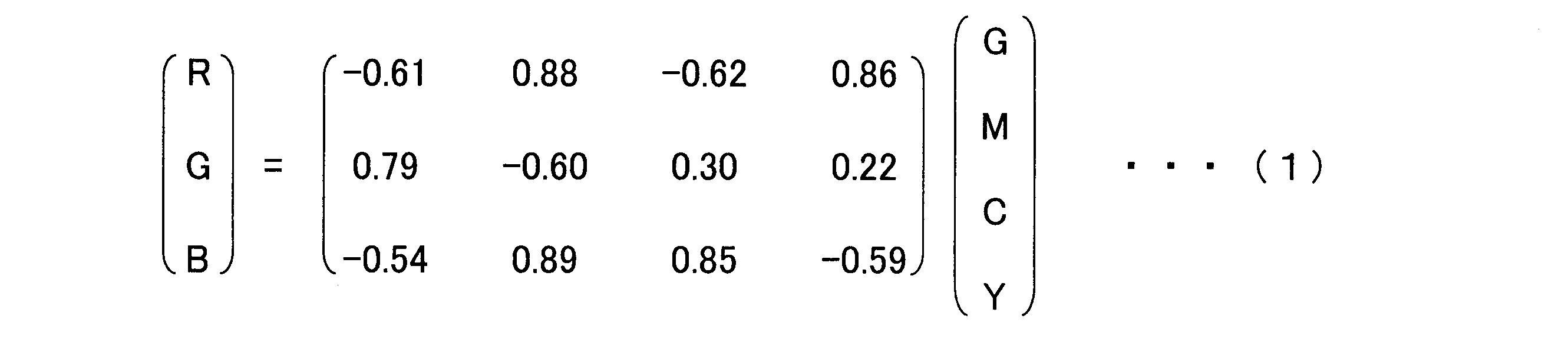
上述した動作を行い、CMYGの色情報をRGBの色情報に変換することができる。
しかしながら、原色系のカラーフィルタが搭載された撮像素子では、補色系のカラーフィルタが搭載された撮像素子よりもカラーフィルタの透過波長帯域が狭いために、光の透過率が悪くなり、感度が低くなるという問題がある。一方、補色系のカラーフィルタが搭載された撮像素子を用いる場合、CMYGの色情報からRGBの色情報に変換して画像を生成するため、上記の式(1)に示したような行列演算を行う。式(1)では、RGBのカラーフィルタやCMYGのカラーフィルタの製造ばらつき等が考慮されていないため、各画素におけるRGBの色再現性の精度が低下するという問題がある。
本発明は、上記課題を解決するためになされたものであり、感度および色再現性の精度を高くすることができる撮像素子を提供することを目的とする。
本発明の第1の態様に係る撮像素子は、第1基板と、前記第1基板に規則的に配置され、照射された光の強度に対応する第1の信号を出力する複数の第1受光素子と、前記第1受光素子の受光面の各々に配置され、少なくとも第2波長帯域と第3波長帯域とを包含する第1波長帯域の光を透過する複数の第1カラーフィルタと、前記第1基板を透過した光が照射されるように配置された第2基板と、前記第2基板に規則的に配置され、照射された光の強度に対応する第2の信号を出力する複数の第2受光素子と、前記第2受光素子の受光面の各々に配置され、前記第2波長帯域の光を透過する複数の第2カラーフィルタと、前記第1の信号と前記第2の信号とを用いて、前記複数の第1受光素子の各々に対応する画素信号を生成する信号処理部と、を備える。
本発明の第2の態様の撮像素子によれば、上記第1の態様において、前記第1波長帯域は、RGB表色系に対するCMY補色系における、マゼンタ色(M)の光の波長帯域である場合、前記第3波長帯域は、前記RGB表色系における、青色(B)の光の波長帯域であり、前記第1波長帯域は、RGB表色系に対するCMY補色系における、黄色(Y)の光の波長帯域である場合、前記第3波長帯域は、前記RGB表色系における、緑色(G)の光の波長帯域であり、前記第2波長帯域は、前記RGB表色系における、赤色(R)の光の波長帯域であってもよい。
本発明の第3の態様の撮像素子によれば、上記第1の態様において、前記第1基板に規則的に配置され、照射された光の強度に対応する第3の信号を出力する複数の第3受光素子と、前記第3受光素子の受光面の各々に配置され、少なくとも第5波長帯域を包含する第4波長帯域の光を透過する複数の第3カラーフィルタと、前記第2基板に規則的に配置され、照射された光の強度に対応する第4の信号を出力する複数の第4受光素子と、前記第4受光素子の受光面の各々に配置され、第5波長帯域の光を透過する複数の第4カラーフィルタと、を備え、前記信号処理部は、前記第3の信号と前記第4の信号とを用いて、前記複数の第3受光素子の各々に対応する前記画素信号を生成してもよい。
本発明の第4の態様の撮像素子によれば、上記第3の態様において、前記第4波長帯域は、RGB表色系に対するCMY補色系における、シアン色(C)の光の波長帯域または黄色(Y)の光の波長帯域であり、前記第5波長帯域は、前記RGB表色系における、緑色(G)の光の波長帯域であってもよい。
本発明の第5の態様の撮像素子によれば、上記第3の態様において、前記第4波長帯域は、前記第5波長帯域と等しくてもよい。
本発明の第6の態様の撮像素子によれば、上記第1の態様において、前記第2受光素子の前記受光面の受光面積は、前記第1受光素子の前記受光面の受光面積より大きくてもよい。また、前記複数の前記第2受光素子の各々は、前記複数の前記第1受光素子に1対1の対応関係となるように配置されていてもよい。
上記各態様の撮像素子は、第1基板と、複数の第1受光素子と、複数の第1カラーフィルタと、第2基板と、複数の第2受光素子と、複数の第2カラーフィルタと、信号処理部とを備える。複数の第1受光素子は、第1基板に規則的に配置され、照射された光の強度に対応する第1の信号を出力する。複数の第1カラーフィルタは、第1受光素子の受光面の各々に配置され、少なくとも第2波長帯域と第3波長帯域とを包含する第1波長帯域の光を透過する。第2基板は、第1基板を透過した光が照射されるように配置される。複数の第2受光素子は、第2基板に規則的に配置され、照射された光の強度に対応する第2の信号を出力する。複数の第2カラーフィルタは、第2受光素子の受光面の各々に配置され、第2波長帯域の光を透過する。信号処理部は、第1の信号と第2の信号とを用いて、複数の第1受光素子の各々に対応する画素信号を生成する。これにより、撮像素子の感度および色再現性の精度を高くすることができる。
(第1の実施形態)
以下、本発明の第1の実施形態について図面を参照して説明する。図1は、本実施形態における撮像素子100の断面を示した断面図である。図1に示すように、撮像素子100は、第1の基板101(第1基板)と、第2の基板102(第2基板)と、補色系カラーフィルタ103と、原色系カラーフィルタ104と、接続部105と、信号処理部106とを備えている。第1の基板101は、シリコンチップ上に形成されており複数の第1の画素を備えている。第2の基板102は、シリコンチップ上に形成されており複数の第2の画素を備えている。なお、補色系カラーフィルタ103は、RGB表色系に対するCMY補色系のカラーフィルタである。
以下、本発明の第1の実施形態について図面を参照して説明する。図1は、本実施形態における撮像素子100の断面を示した断面図である。図1に示すように、撮像素子100は、第1の基板101(第1基板)と、第2の基板102(第2基板)と、補色系カラーフィルタ103と、原色系カラーフィルタ104と、接続部105と、信号処理部106とを備えている。第1の基板101は、シリコンチップ上に形成されており複数の第1の画素を備えている。第2の基板102は、シリコンチップ上に形成されており複数の第2の画素を備えている。なお、補色系カラーフィルタ103は、RGB表色系に対するCMY補色系のカラーフィルタである。
第1の基板101が備える複数の第1の画素は、光電変換素子(第1受光素子)と信号読み出し回路とを備えている。第2の基板102が備える複数の第2の画素は、光電変換素子(第2受光素子)と信号読み出し回路とを備えている。光電変換素子は、露光量に応じた信号電荷を読み出し回路に対して出力する。信号読み出し回路は、信号電荷を電気信号として出力する。第1の基板101の受光面側には、補色系カラーフィルタ103が形成されている。補色系カラーフィルタ103の配列については後述する。第2の基板102の受光面側には、原色系カラーフィルタ104が形成されている。原色系カラーフィルタ104の配列については後述する。
第1の基板101と第2の基板102とは段積み(スタック)されている。図示する例では、第1の基板101の受光面とは反対側に、第2の基板102が配置されている。第2の基板102の受光面は、第1の基板101が存在する側である。また、第1の基板101と第2の基板102との間には接続部105が構成されており、第1の基板101と第2の基板102とは接続部105を介して電気的に接続されている。すなわち、第1の基板101と第2の基板102とは接続部105を介して貼り合わせている。
第1の基板101が備えている第1の画素の各々は第1の信号を取得する。第2の基板102が備えている第2の画素の各々は第2の信号を取得する。第1の基板101で取得した第1の信号と、第2の基板102で取得した第2の信号とは、接続部105を介して信号処理部106に出力される。信号処理部106は、第1の基板101と第2の基板102とのいずれかに設けるようにしてもよく、第1の基板101および第2の基板102以外に設けるようにしてもよい。信号処理部106は、第1の信号と第2の信号とを用いて、第1の画素の各々の画素信号を生成する。すなわち、信号処理部106は、RGB(赤色、緑色、青色)の色情報を有するフルカラー画像を生成する。
ここで、第1の基板101は裏面照射型の撮像基板であり、第1の基板101の厚さは数um程度であり、薄い。そのために、第1の基板101の受光面側から入射した光の一部は透過し、第2の基板102の受光面側に入射する。なお、シリコンの深さごとの光に対する吸収率は波長によって異なる。シリコンの浅い部分では、波長が短い光の吸収率は高く、波長が長い光の吸収率は低い。すなわち、厚さが薄い第1の基板101では、波長が短い光を吸収するが、波長が長い光を吸収しない。例えば、本実施形態では、第1の基板101の厚みを約3μmとする。この場合、500nm以上の波長の光(緑色(G)の光のうち高波長側の光、赤色(R)の光、および赤外(IR)光)の一部は吸収されずに、第1の基板101を透過する。また、第2の基板102は、表面照射型の撮像基板であり、第1の基板101よりも厚い。そのために、第2の基板102では、第1の基板101を透過した透過光を検出する。
図2は、本実施形態における補色系カラーフィルタ103の配列と、原色系カラーフィルタ104の配列とを示した概略図である。図2に示すように、第1の基板101には、4行4列の二次元状に規則的に配列された計16個の第1の画素1011-1~1011-16(第1受光素子)が含まれている。また、第2の基板102には、4行4列の二次元状に規則的に配列された計16個の第2の画素1021-1~1021-16(第2受光素子)が含まれている。なお、第1の基板101に含まれる第1の画素1011と第2の基板102に含まれる第2の画素1021との数および配列は図示する例に限らず、どのような数および配列でもよい。
第1の基板101に形成された補色系カラーフィルタ103は、マゼンタ色(M(=B+R))の光を透過するカラーフィルタMと、黄色(Y(=G+R))の光を透過するカラーフィルタYとの複数のカラーフィルタ(第1カラーフィルタ)が配列されたフィルタである。第1の画素1011-1,1011-3,1011-6,1011-8,1011-9,1011-11,1011-14,1011-16には、黄色(Y)の光を透過するカラーフィルタYが形成されている。第1の画素1011-2,1011-4,1011-5,1011-7,1011-10,1011-12,1011-13,1011-15にはマゼンタ色(M)の光を透過するカラーフィルタMが形成されている。
また、縦と横に隣接する4つの第1の画素1011を1組の単位画素領域121とする。例えば、1組の単位画素領域121は、マゼンタ色の光を透過するカラーフィルタMが形成された2つの第1の画素1011-2,1011-5と、黄色の光を透過するカラーフィルタYが形成された2つの第1の画素1011-1,1011-6とで構成されている。
第2の基板102に形成された原色系カラーフィルタ104は、赤色(R)の光を透過するカラーフィルタR(第2カラーフィルタ)が複数配列されたフィルタである。第2の画素1021-1~1021-16には赤色(R)の光を透過するカラーフィルタRが形成されている。
また、縦と横に隣接する4つの第2の画素1021を1組の単位画素領域122とする。例えば、1組の単位画素領域122は、赤色の光を透過するカラーフィルタRが形成された4つの画素1021-1,1021-2,1021-5,1021-6で構成されている。
また、第1の基板101に含まれる第1の画素1011-1~1011-16と、第2の基板102に含まれる第2の画素1021-1~1021-16とは、1対1の対応関係となるように配置されている。例えば、第1の画素1011-1を透過した光は、対応する第2の画素1021-1のみに照射されるように、第1の画素1011-1と第2の画素1021-1とは配置されている。また、第1の画素1011-2を透過した光は、対応する第2の画素1021-2のみに照射されるように、第1の画素1011-2と第2の画素1021-2とは配置されている。同様に、第1の画素1011-3~1011-16と第2の画素1021-3~1021-16とについても図示するとおり配置されている。
上述したとおり、第1の基板101は、500nm以上の波長の光(緑色(G)の光のうち高波長側の光、赤色(R)の光、および赤外(IR)光)を透過する。ここで、赤色(R)(第2波長帯域)の光と、緑色(G)(第3波長帯域)の光と、青色(B)(第3波長帯域)の光のうち、赤色(R)の光が第1の基板101を最も透過しやすい。
第1の基板101を透過した500nm以上の波長の光は、第2の基板102に照射される。従って、本実施形態では図2に示すように、第2の基板102に形成する原色系カラーフィルタ104には、赤色(R)の光を透過するカラーフィルタRのみを用いる。また、第1の基板101に形成する補色系カラーフィルタ103には、第2の基板102に赤色(R)の光を透過させるために、マゼンタ色(M(=B+R))(第1波長帯域)の光を透過するカラーフィルタMと、黄色(Y(=G+R))(第1波長帯域)の光を透過するカラーフィルタYとを用いる。
第1の基板101を透過した500nm以上の波長の光は、第2の基板102に照射される。従って、本実施形態では図2に示すように、第2の基板102に形成する原色系カラーフィルタ104には、赤色(R)の光を透過するカラーフィルタRのみを用いる。また、第1の基板101に形成する補色系カラーフィルタ103には、第2の基板102に赤色(R)の光を透過させるために、マゼンタ色(M(=B+R))(第1波長帯域)の光を透過するカラーフィルタMと、黄色(Y(=G+R))(第1波長帯域)の光を透過するカラーフィルタYとを用いる。
この構成により、第1の基板101で取得する第1の信号は、マゼンタ色(M)の光の強度に応じた信号Mと、黄色(Y)の光の強度に応じた信号Yである。また、第2の基板102で取得する第2の信号は、赤色(R)の光の強度に応じた信号Rである。信号処理部106は、この第1の信号と第2の信号とを用いて、各第1の画素1011のRGBの色情報を精度良く算出する。なお、信号処理部106によるRGBの色情報の算出方法の詳細については後述する。
次に、撮像素子100の動作について説明する。本実施形態では、撮像素子100をデジタルカメラに用いた場合について説明する。撮像素子100には、赤外光(IR)カットフィルタによって赤外光がカットされた光が照射される。
第1の基板101の受光面側に光が入射される。第1の画素1011-1~1011-16の各々は、補色系カラーフィルタ103を透過した光を検出し、第1の信号を出力する。具体的には、黄色(Y)の光を透過するカラーフィルタYが形成された第1の画素1011-1,1011-3,1011-6,1011-8,1011-9,1011-11,1011-14,1011-16は、黄色(Y)の光の強度に応じた第1の信号を出力する。また、マゼンタ色(M)の光を透過するカラーフィルタMが形成された第1の画素1011-2,1011-4,1011-5,1011-7,1011-10,1011-12,1011-13,1011-15は、マゼンタ色(M)の光の強度に応じた第1の信号を出力する。
また、第2の基板102の第2の画素1021-1~1021-16の各々は、補色系カラーフィルタ103と、第1の基板101と、原色系カラーフィルタ104とを透過した光を検出し、第2の信号を出力する。具体的には、赤色(R)の光を透過するカラーフィルタRが形成された第2の画素1021-1~1021-16の各々は、赤色(R)の光の強度に応じた第2の信号を出力する。
第1の画素1011-1~1011-16が出力した第1の信号及び第2の画素1021-1~1021-16が出力した第2の信号は、それぞれ接続部105を介して、信号処理部106に出力される。信号処理部106は、第1の信号と第2の信号とを用いて、各第1の画素1011-1~1011-16のRGBの色情報を有するフルカラー画像を生成する。
次に、第1の画素1011-1~1011-16が出力する第1の信号と、第2の画素1021-1~1021-16が出力する第2の信号とについて説明する。図3は、本実施形態における第1の画素1011-1~1011-16が出力する第1の信号と、第2の画素1021-1~1021-16が出力する第2の信号とを示した概略図である。
図3に示すように、第1の基板101には、第1の画素1011-1,1011-2,1011-5,1011-6で構成される単位画素領域121が示されている。また、第2の基板102には、第2の画素1021-1,1021-2,1021-5,1021-6で構成される単位画素領域122が示されている。
上述したとおり、第1の画素1011-1,1011-3,1011-6,1011-8,1011-9,1011-11,1011-14,1011-16には、黄色(Y)の光を透過するカラーフィルタYが形成されている。黄色(Y)は青色(B)の補色(=緑色(G)+赤色(R))である。ここで、第1の画素1011-1,1011-3,1011-6,1011-8,1011-9,1011-11,1011-14,1011-16が出力する第1の信号を、αG+βRとする。Gは緑色の光の強度に応じた値である。Rは赤色の光の強度に応じた値である。αおよびβの値は、カラーフィルタYの製造時に決まる値であり、固定値である。
また、上述したとおり、第1の画素1011-2,1011-4,1011-5,1011-7,1011-10,1011-12,1011-13,1011-15には、マゼンタ色(M)の光を透過するカラーフィルタMが形成されている。マゼンタ色(M)は緑色(G)の補色(=青色(B)+赤色(R))である。ここで、第1の画素1011-2,1011-4,1011-5,1011-7,1011-10,1011-12,1011-13,1011-15が出力する第1の信号を、δB+εRとする。Bは青色の光の強度に応じた値である。Rは赤色の光の強度に応じた値である。δおよびεの値は、カラーフィルタMの製造時に決まる値であり、固定値である。
また、上述したとおり、第2の画素1021-1~1021-16には、赤色(R)の光を透過するカラーフィルタRが形成されている。第2の画素1021-1,1021-3,1021-6,1021-8,1021-9,1021-11,1021-14,1021-16には、第1の画素1011-1,1011-3,1011-6,1011-8,1011-9,1011-11,1011-14,1011-16を透過した光が入射される。すなわち、第2の画素1021-1,1021-3,1021-6,1021-8,1021-9,1021-11,1021-14,1021-16には、カラーフィルタYと、第1の基板101と、カラーフィルタRとを透過した光が入射される。ここで、第2の画素1021-1,1021-3,1021-6,1021-8,1021-9,1021-11,1021-14,1021-16が出力する第2の信号を、γRとする。Rは赤色の光の強度に応じた値である。γの値は、カラーフィルタRの製造時に決まる値であり、固定値である。
また、第1の基板101にてカラーフィルタYが形成された第1の画素1011-2,1011-4,1011-5,1011-7,1011-10,1011-12,1011-13,1011-15が透過する赤色の光に着目すると、βとγとの比は製造時に決まるパラメータである。例えば、カラーフィルタYおよびカラーフィルタRの透過特性や、第1の基板101および第2の基板102の厚みなどに基づいて決まる第1の基板101および第2の基板102の分光感度によって、βとγとの比は決まる。
第2の画素1021-2,1021-5には、第1の画素1011-2,1011-5を透過した光が入射される。すなわち、第2の画素1021-2,1021-5には、カラーフィルタMと、第1の基板101と、カラーフィルタRとを透過した光が入射される。ここで、第2の画素1021-2,1021-5が出力する第2の信号を、ηRとする。Rは赤色の光の強度に応じた値である。ηの値は、カラーフィルタRの製造時に決まる値であり、固定値である。
また、第1の基板101にてカラーフィルタMが形成された第1の画素1011-2,1011-4,1011-5,1011-7,1011-10,1011-12,1011-13,1011-15が透過する赤色の光に着目すると、εとηとの比は製造時に決まるパラメータである。例えば、カラーフィルタMおよびカラーフィルタRの透過特性や、第1の基板101および第2の基板102の厚みなどに基づいて決まる第1の基板101および第2の基板102の分光感度によって、εとηとの比は決まる。
次に、信号処理部106によるRGBの色情報の算出方法の詳細について説明する。信号処理部106は、第1の基板101の第1の画素1011-1~1011-16が出力する第1の信号と、第2の基板102の第2の画素1021-1~1021-16が出力する第2の信号とを用いて、各第1の画素1011-1~1011-16のRGBの色情報を算出する。なお、信号処理部106は、以下に示す第1のステップと第2のステップとの2つのステップを実行することで、各第1の画素1011-1~1011-16のRGBの色情報を算出する。
<第1のステップ>
第1のステップでは、信号処理部106は、補色系カラーフィルタ103を透過した第1の信号と、原色系カラーフィルタ104を透過した第2の信号とを用いて演算処理を行い、各第1の画素1011-1~1011-16において、RGBの色情報のうち2色の色情報を分離して算出する。
第1のステップでは、信号処理部106は、補色系カラーフィルタ103を透過した第1の信号と、原色系カラーフィルタ104を透過した第2の信号とを用いて演算処理を行い、各第1の画素1011-1~1011-16において、RGBの色情報のうち2色の色情報を分離して算出する。
例えば、黄色(Y(=G+R))の光を透過するカラーフィルタYが形成された第1の画素1011-1が出力した第1の信号「αG+βR」と、赤色の光を透過するカラーフィルタRが形成された第2の画素1021-1が出力した第2の信号「γR」とを用いて演算処理を行い、第1の画素1011-1における「G」の色情報と「R」の色情報とを算出する。
具体的には、α、β、γの値は既知であり、βとγの比率も既知であるため、第2の信号「γR」を用いて、第1の信号「αG+βR」のうち、「βR」を算出する。これによって、純粋な「R」の色情報を算出することができる。続いて、第1の信号「αG+βR」から、算出した「βR」を差分して、「αG」を算出する。これによって、純粋な「G」の色情報を算出することができる。すなわち、上述した演算方法により、カラーフィルタYが設けられた第1の画素1011-1における純粋な「G」と「R」の色情報をそれぞれ算出することができる。なお、第1の画素1011-1,1011-3,1011-6,1011-8,1011-9,1011-11,1011-14,1011-16についても同様の処理を行い、純粋な「G」と「R」の色情報をそれぞれ算出する。
また、例えば、マゼンタ色(M(=B+R))の光を透過するカラーフィルタMが形成された第1の画素1011-2が出力した第1の信号「δB+εR」と、赤色の光を透過するカラーフィルタRが形成された第2の画素1021-2が出力した第2の信号「ηR」とを用いて演算処理を行い、第1の画素1011-2における「B」の色情報と「R」の色情報とを算出する。
具体的には、δ、ε、ηの値は既知であり、εとηの比率も既知であるため、第2の信号「ηR」を用いて、第1の信号「δB+εR」のうち、「εR」を算出する。これによって、純粋な「R」の色情報を算出することができる。続いて、第1の信号「δB+εR」から、算出した「εR」を差分して、「δB」を算出する。これによって、純粋な「B」の色情報を算出することができる。すなわち、上述した演算方法により、カラーフィルタMが設けられた第1の画素1011-2における純粋な「B」の色情報と「R」の色情報とを算出することができる。なお、第1の画素1011-2,1011-4,1011-5,1011-7,1011-10,1011-12,1011-13,1011-15についても同様の処理を行い、純粋な「B」の色情報と「R」の色情報とを算出する。
上述した第1のステップの演算を行うことにより、各第1の画素1011-1~1011-16において、RGBの色情報のうち、2色の色情報を算出することができる。図4は、本実施形態において、第1のステップの演算を行った結果を示した概略図である。図中の「,」は、補色系カラーフィルタ103が配置された第1の画素1011-1~1011-16において、RGBの色情報のうち2色の色情報を分離して算出したことを示している。
第1のステップの演算を行うことにより、図4に示すように、カラーフィルタYが形成された第1の画素1011-1,1011-3,1011-6,1011-8,1011-9,1011-11,1011-14,1011-16において、それぞれ「αG,βR」の色情報を得ることができる。なお、上述したとおり、第2の画素1021-1,1021-3,1021-6,1021-8,1021-9,1021-11,1021-14,1021-16が得る色情報は、それぞれ「γR」である。
また、第1のステップの演算を行うことにより、図4に示すように、カラーフィルタMが形成された第1の画素1011-2,1011-4,1011-5,1011-7,1011-10,1011-12,1011-13,1011-15において、それぞれ「δB,εR」の色情報を得ることができる。なお、上述したとおり、第2の画素1021-2,1021-4,1021-5,1021-7,1021-10,1021-12,1021-13,1021-15が得る色情報は、それぞれ「ηR」である。
<第2のステップ>
第2のステップでは、各第1の画素1011-1~1011-16において、第1のステップで算出した2色の色情報を用いて、残り1色の色情報を算出する。残り1色の色情報は、従来知られているデモザイキング処理と同様に、隣接または近傍に配置されている第1の画素1011-1~1011-16の色情報を用いて線形補間等を行い、算出する。
第2のステップでは、各第1の画素1011-1~1011-16において、第1のステップで算出した2色の色情報を用いて、残り1色の色情報を算出する。残り1色の色情報は、従来知られているデモザイキング処理と同様に、隣接または近傍に配置されている第1の画素1011-1~1011-16の色情報を用いて線形補間等を行い、算出する。
例えば、黄色(Y(=G+R))の光を透過するカラーフィルタYが形成された第1の画素1011-6では、「B」の色情報が欠けている。図4において、第1の画素1011-6に隣接する第1の画素1011-1,1011-2,1011-3,1011-5,1011-7,1011-9,1011-10,1011-11に着目すると、第1の画素1011-2,1011-5,1011-7,1011-10において、「B」の色情報を得ている。
信号処理部106は、この4つの第1の画素1011-2,1011-5,1011-7,1011-10の「B」の色情報を用いて補間処理を行い、第1の画素1011-6における「B」の色情報を算出する。例えば、信号処理部106は、従来知られている原色系のデモザイキング処理と同様に線形補間等を用いて欠落した色情報を算出する。なお、第1の画素1011-1,1011-3,1011-8,1011-9,1011-11,1011-14,1011-16についても同様の処理を行い、「B」の色情報をそれぞれ算出する。
また、例えば、マゼンタ色(M(=B+R))の光を透過するカラーフィルタMが形成された第1の画素1011-10では、「G」の色情報が欠けている。図4において、第1の画素1011-10に隣接する第1の画素1011-5,1011-6,1011-7,1011-9,1011-11,1011-13,1011-14,1011-15に着目すると、第1の画素1011-6,1011-9,1011-11,1011-14において、「G」の色情報を得ている。
信号処理部106は、この4つの第1の画素1011-6,1011-9,1011-11,1011-14の「G」の色情報を用いて補間処理を行い、第1の画素1011-10における「G」の色情報を算出する。例えば、信号処理部106は、従来知られている原色系のデモザイキング処理と同様に線形補間等を用いて欠落した色情報を算出する。なお、第1の画素1011-2,1011-4,1011-5,1011-7,1011-12,1011-13,1011-15についても同様の処理を行い、「G」の色情報をそれぞれ算出する。
上述した第1のステップと第2のステップを実行することにより、信号処理部106は、各第1の画素1011-1~1011-16のRGBの色情報を算出することができる。
例えば、色再現性が良いと言われている従来知られている原色系のベイヤー配列のカラーフィルタを備えた撮像素子では、デモザイキングを行う際に「B」の色情報を取得する画素に着目した場合、隣接する8つの画素のうち、「G」の色情報を取得する画素は4画素であり、「R」の色情報を取得する画素は4画素である。また、「G」の色情報を取得する画素に着目した場合、隣接する8つの画素のうち、「B」の色情報を取得する画素は2画素であり、「R」の色情報を取得する画素は2画素である。また、「R」の色情報を取得する画素に着目した場合、隣接する8つの画素のうち、「B」の色情報を取得する画素は4画素であり、「G」の色情報を取得する画素は4画素である。
一方、本実施形態では、第1の画素1011の全てが「R」の色情報を取得している。また、デモザイキング処理を行う際に、「Y(=G+R))」の色情報を取得する第1の画素1011に着目した場合、隣接する8つの画素のうち、「B」の色情報を取得する画素は4画素である。また、「M(=B+R)」の色情報を取得する第1の画素1011に着目した場合、隣接する8つの画素のうち「G」の色情報を取得する画素は4画素である。
このように、本実施形態では、デモザイキング処理を行う際に、欠けている色情報を取得している隣接画素が増加するために、色補間精度が向上する。また、第1の画素1011には補色系カラーフィルタ103が形成されているため、第1の画素1011の感度は高感度である。従って、本実施形態の撮像素子100は、感度および色再現性の精度を高くすることができる。
(第2の実施形態)
次に、本発明の第2の実施形態について説明する。本実施形態の補色系カラーフィルタの配列及び原色系カラーフィルタの配列は、第1実施形態と異なる。なお、本実施形態における撮像素子200のその他の構成は、第1の実施形態における撮像素子100の構成と同様である。
次に、本発明の第2の実施形態について説明する。本実施形態の補色系カラーフィルタの配列及び原色系カラーフィルタの配列は、第1実施形態と異なる。なお、本実施形態における撮像素子200のその他の構成は、第1の実施形態における撮像素子100の構成と同様である。
図5は、本実施形態における補色系カラーフィルタ203の配列と、原色系カラーフィルタ204の配列とを示した概略図である。図示する例では、第1の基板201には、4行4列の二次元状に配列された計16個の第1の画素2011-1~2011-16が含まれている。また、第2の基板202には、4行4列の二次元状に配列された計16個の第2の画素2021-1~2021-16が含まれている。なお、第1の基板201に含まれる第1の画素2011と第2の基板202に含まれる第2の画素2021との数および配列は図示する例に限らず、どのような数および配列でもよい。
第1の基板201に形成された補色系カラーフィルタ203は、マゼンタ色(M(=B+R))の光を透過するカラーフィルタMと、黄色(Y(=G+R))の光を透過するカラーフィルタYと、シアン色(C(=B+G))の光を透過するカラーフィルタCとが配列されたフィルタである。第1の画素2011-1,2011-3,2011-9,2011-11(第1受光素子)には、黄色(Y)(第1波長帯域)の光を透過するカラーフィルタY(第1カラーフィルタ)が形成されている。第1の画素2011-2,2011-4,2011-5,2011-7,2011-10,2011-12,2011-13,2011-15(第1受光素子)には、マゼンタ色(M)(第1波長帯域)の光を透過するカラーフィルタM(第1カラーフィルタ)が形成されている。第1の画素2011-6,2011-8,2011-14,2011-16(第3受光素子)には、シアン色(C)(第4波長帯域)の光を透過するカラーフィルタC(第3カラーフィルタ)が形成されている。
また、縦と横に隣接する4つの第1の画素2011を1組の単位画素領域221とする。例えば、1組の単位画素領域221は、マゼンタ色の光を透過するカラーフィルタMが形成された2つの第1の画素2011-2,2011-5と、黄色の光を透過するカラーフィルタYが形成された1つの第1の画素2011-1と、シアン色の光を透過するカラーフィルタCが形成された1つの第1の画素2011-6とで構成されている。
第2の基板202に形成された原色系カラーフィルタ204は、赤色(R)の光を透過するカラーフィルタRと、緑色(G)の光を透過するカラーフィルタGとが配列されたフィルタである。第2の画素2021-1~2021-5,2021-7,2021-9~2021-13,2021-15(第2受光素子)には赤色(R)(第2波長帯域)の光を透過するカラーフィルタR(第2カラーフィルタ)が形成されている。第2の画素2021-6,2021-8,2021-14,2021-16(第4受光素子)には緑色(G)(第5波長帯域)の光を透過するカラーフィルタG(第4カラーフィルタ)が形成されている。
また、縦と横に隣接する4つの第2の画素2021を1組の単位画素領域222とする。例えば、1組の単位画素領域222は、赤色の光を透過するカラーフィルタRが形成された3つの第2の画素2021-1,2021-2,2021-5と、緑色の光を透過するカラーフィルタGが形成された1つの第2の画素2021-6とで構成されている。
また、第1の基板201に含まれる第1の画素2011-1~2011-16と、第2の基板202に含まれる第2の画素2021-1~2021-16とは、1対1の対応関係となるように配置されている。例えば、第1の画素2011-1を透過した光は、対応する第2の画素2021-1のみに照射されるように、第1の画素2011-1と第2の画素2021-1とは配置されている。また、第1の画素2011-2を透過した光は、対応する第2の画素2021-2のみに照射されるように、第1の画素2011-2と第2の画素2021-2とは配置されている。同様に、第1の画素2011-3~2011-16と第2の画素2021-3~2021-16とについても図示するとおり配置されている。
上述したとおり、シアン色(C)の光を透過するカラーフィルタCが配置された第1の画素2011-6,2011-8,2011-14,2011-16に対応する第2の画素2021-6,2021-8,2021-14,2021-16には、緑色(G)の光を透過するカラーフィルタGが形成されている。この理由は、シアン色(C(=B+G))の光を透過するカラーフィルタCは、赤色(R)の光を透過せず、青色(B)の光と緑色(G)の光を透過するためである。
次に、撮像素子200の動作について説明する。本実施形態では、撮像素子200をデジタルカメラに用いた場合について説明する。撮像素子200には、赤外光(IR)カットフィルタによって赤外光がカットされた光が照射される。
第1の基板201の受光面側に光が入射される。第1の画素2011-1~2011-16の各々は、補色系カラーフィルタ203を透過した光を検出し、第1の信号または第3の信号を出力する。具体的には、黄色(Y)の光を透過するカラーフィルタYが形成された第1の画素2011-1,2011-3,2011-9,2011-11は、黄色(Y)の光の強度に応じた第1の信号を出力する。また、マゼンタ色(M)の光を透過するカラーフィルタMが形成された第1の画素2011-2,2011-4,2011-5,2011-7,2011-10,2011-12,2011-13,2011-15は、マゼンタ色(M)の光の強度に応じた第1の信号を出力する。また、シアン色(C)の光を透過するカラーフィルタCが形成された第1の画素2011-6,2011-8,2011-14,2011-16は、シアン色(C)の光の強度に応じた第3の信号を出力する。
また、第2の基板202の第2の画素2021-1~2021-16の各々は、補色系カラーフィルタ203と、第1の基板201と、原色系カラーフィルタ204とを透過した光を検出し、第2の信号または第4の信号を出力する。具体的には、赤色(R)の光を透過するカラーフィルタRが形成された第2の画素2021-1~2021-5,2021-7,2021-9~2021-13,2021-15は、赤色(R)の光の強度に応じた第2の信号を出力する。また、緑色(G)の光を透過するカラーフィルタGが形成された第2の画素2021-6,2021-8,2021-14,2021-16は、緑色(G)の光の強度に応じた第4の信号を出力する。
第1の画素2011-1~2011-16が出力した第1の信号および第3の信号と、第2の画素2021-1~2021-16が出力した第2の信号と、第4の信号とは、それぞれ接続部105を介して、信号処理部106に出力される。信号処理部106は、第1の信号~第4の信号を用いて、各第1の画素2011-1~2011-16のRGBの色情報を有するフルカラー画像を生成する。
次に、第1の画素2011-1~2011-16が出力する第1の信号および第3の信号と、第2の画素2021-1~2021-16が出力する第2の信号および第4の信号とについて説明する。図6は、本実施形態における第1の画素2011-1~2011-16が出力する第1の信号および第3の信号と、第2の画素2021-1~2021-16が出力する第2の信号および第4の信号とを示した概略図である。
上述したとおり、第1の画素2011-1,2011-3,2011-9,2011-11には、黄色(Y)の光を透過するカラーフィルタYが形成されている。黄色(Y)は青色(B)の補色(=緑色(G)+赤色(R))である。ここで、第1の画素2011-1,2011-3,2011-9,2011-11が出力する第1の信号を、αG+βRとする。Gは緑色の光の強度に応じた値である。Rは赤色の光の強度に応じた値である。αおよびβの値は、カラーフィルタYの製造時に決まる値であり、固定値である。
また、上述したとおり、第1の画素2011-2,2011-4,2011-5,2011-7,2011-10,2011-12,2011-13,2011-15には、マゼンタ色(M)の光を透過するカラーフィルタMが形成されている。マゼンタ色(M)は緑色(G)の補色(=青色(B)+赤色(R))である。ここで、第1の画素2011-2,2011-4,2011-5,2011-7,2011-10,2011-12,2011-13,2011-15が出力する第1の信号を、δB+εRとする。Bは青色の光の強度に応じた値である。Rは赤色の光の強度に応じた値である。δおよびεの値は、カラーフィルタMの製造時に決まる値であり、固定値である。
また、上述したとおり、第1の画素2011-6,2011-8,2011-14,2011-16には、シアン色(C)の光を透過するカラーフィルタCが形成されている。
シアン色(C)は赤色(R)の補色(=青色(B)+緑色(G))である。ここで、第1の画素2011-6,2011-8,2011-14,2011-16が出力する第3の信号を、κB+λGとする。Bは青色の光の強度に応じた値である。Gは緑色の光の強度に応じた値である。κおよびλの値は、カラーフィルタCの製造時に決まる値であり、固定値である。
シアン色(C)は赤色(R)の補色(=青色(B)+緑色(G))である。ここで、第1の画素2011-6,2011-8,2011-14,2011-16が出力する第3の信号を、κB+λGとする。Bは青色の光の強度に応じた値である。Gは緑色の光の強度に応じた値である。κおよびλの値は、カラーフィルタCの製造時に決まる値であり、固定値である。
また、上述したとおり、第2の画素2021-1~2021-5,2021-7,2021-9~2021-13,2021-15には、赤色(R)の光を透過するカラーフィルタRが形成されている。第2の画素2021-1,2021-3,2021-9,2021-11には、第1の画素2011-1,2011-3,2011-9,2011-11を透過した光が入射される。すなわち、第2の画素2021-1,2021-3,2021-9,2021-11には、カラーフィルタYと、第1の基板201と、カラーフィルタRとを透過した光が入射される。ここで、第2の画素2021-1,2021-3,2021-9,2021-11が出力する第2の信号を、γRとする。Rは赤色の光の強度に応じた値である。γの値は、カラーフィルタRの製造時に決まる値であり、固定値である。
また、第1の基板201にてカラーフィルタYが形成された第1の画素2011-1,2011-3,2011-9,2011-11が透過する赤色の光に着目すると、βとγとの比は製造時に決まるパラメータである。例えば、カラーフィルタYおよびカラーフィルタRの透過特性や、第1の基板201および第2の基板202の厚みなどに基づいて決まる第1の基板201および第2の基板202の分光感度によって、βとγとの比は決まる。
第2の画素2021-2,2021-4,2021-5,2021-7,2021-10,2021-12,2021-13,2021-15には、第1の画素2011-2,2011-4,2011-5,2011-7,2011-10,2011-12,2011-13,2011-15を透過した光が入射される。すなわち、第2の画素2021-2,2021-4,2021-5,2021-7,2021-10,2021-12,2021-13,2021-15には、カラーフィルタMと、第1の基板201と、カラーフィルタRとを透過した光が入射される。ここで、第2の画素2021-2,2021-4,2021-5,2021-7,2021-10,2021-12,2021-13,2021-15が出力する第2の信号を、ηRとする。Rは赤色の光の強度に応じた値である。ηの値は、カラーフィルタRの製造時に決まる値であり、固定値である。
また、第1の基板201にてカラーフィルタMが形成された第1の画素2011-2,2011-4,2011-5,2011-7,2011-10,2011-12,2011-13,2011-15が透過する赤色の光に着目すると、εとηとの比は製造時に決まるパラメータである。例えば、カラーフィルタMおよびカラーフィルタRの透過特性や、第1の基板201および第2の基板202の厚みなどに基づいて決まる第1の基板201および第2の基板202の分光感度によって、εとηとの比は決まる。
また、上述したとおり、第2の画素2021-6,2021-8,2021-14,2021-16には緑色(G)の光を透過するカラーフィルタGが形成されている。第2の画素2021-6,2021-8,2021-14,2021-16には、第1の画素2011-6,2011-8,2011-14,2011-16を透過した光が入射される。すなわち、第2の画素2021-6,2021-8,2021-14,2021-16には、カラーフィルタCと、第1の基板201と、カラーフィルタGとを透過した光が入射される。
なお、緑色の光は、500nm以下の波長を含む。また、第1の基板201は500nm以上の波長の光の一部を透過する。よって、第2の基板202には、撮像素子200の受光面に入射された緑色の光のうち、500nm以下の波長の光は届かない。すなわち、第2の画素2021-6,2021-8,2021-14,2021-16は、緑色の光のうち、高波長領域の光を検出する。ここで、第2の画素2021-6,2021-8,2021-14,2021-16が出力する第4の信号を、μG’とする。G’は緑色の光のうち、高波長領域の光の強度に応じた値である。μの値は、カラーフィルタGの製造時に決まる値であり、固定値である。
次に、信号処理部106によるRGBの色情報の算出方法の詳細について説明する。信号処理部106は、第1の基板201の第1の画素2011-1~2011-16が出力する第1の信号および第3の信号と、第2の基板202の第2の画素2021-1~2021-16が出力する第2の信号および第4の信号とを用いて、各第1の画素2011-1~2011-16のRGBの色情報を算出する。なお、信号処理部106は、以下に示す第1のステップと第2のステップとの2つのステップを実行することで、各第1の画素2011-1~2011-16のRGBの色情報を算出する。
<第1のステップ>
第1のステップでは、信号処理部106は、黄色(Y(=G+R))の光を透過するカラーフィルタYが形成された第1の画素2011-1,2011-3,2011-9,2011-11における「G」の色情報と「R」の色情報とを算出する。算出方法は第1の実施形態と同様である。
第1のステップでは、信号処理部106は、黄色(Y(=G+R))の光を透過するカラーフィルタYが形成された第1の画素2011-1,2011-3,2011-9,2011-11における「G」の色情報と「R」の色情報とを算出する。算出方法は第1の実施形態と同様である。
また、信号処理部106は、マゼンタ色(M(=B+R))の光を透過するカラーフィルタMが形成された第1の画素2011-2,2011-4,2011-5,2011-7,2011-10,2011-12,2011-13,2011-15における「B」の色情報と「R」の色情報とを算出する。算出方法は第1の実施形態と同様である。
なお、シアン色(C(=B+G))の光を透過するカラーフィルタCが形成された第1の画素2011-6,2011-8,2011-14,2011-16においては、対応する第2の画素2021-6,2021-8,2021-14,2021-16が、「B」の色情報と「G」の色情報とを保持していないため、「B」の色情報と「G」の色情報とを算出しない。すなわち、第2の画素2021-6,2021-8,2021-14,2021-16が検出したμG’からλGを算出することができないため、カラーフィルタCが形成された第1の画素2011-6,2011-8,2011-14,2011-16では、「B」の色情報と「G」の色情報とを算出しない。
上述した第1のステップの演算を行うことにより、第1の画素2011-1~2011-5,2011-7,2011-9~2011-13,2011-15において、RGBの色情報のうち、2色の色情報を算出することができる。図7は、本実施形態において、第1のステップの演算を行った結果を示した概略図である。図中の「,」は、第1の画素2011-1~2011-5,2011-7,2011-9~2011-13,2011-15において、RGBの色情報のうち2色の色情報を分離して算出したことを示している。
第1のステップの演算を行うことにより、図7に示すように、カラーフィルタYが形成された第1の画素2011-1,2011-3,2011-9,2011-11において、それぞれ「αG,βR」の色情報を得ることができる。なお、上述したとおり、第2の画素2021-1,2021-3,2021-9,2021-11が得る色情報は、それぞれ「γR」である。
また、第1のステップの演算を行うことにより、図示するとおり、カラーフィルタMが形成された第1の画素2011-2,2011-4,2011-5,2011-7,2011-10,2011-12,2011-13,2011-15において、それぞれ「δB,εR」の色情報を得ることができる。なお、上述したとおり、第2の画素2021-2,2021-4,2021-5,2021-7,2021-10,2021-12,2021-13,2021-15が得る色情報は、それぞれ「ηR」である。
また、カラーフィルタCが形成された第1の画素2011-6,2011-8,2011-14,2011-16においては、「B」の色情報と「G」の色情報とを算出しないため、第1の画素2011-6,2011-8,2011-14,2011-16が出力した第1の信号「κB+λG」のままである。なお、上述したとおり、第2の画素2021-6,2021-8,2021-14,2021-16が得る色情報は、それぞれ「μG’」である。
<第2のステップ>
第2のステップでは、各第1の画素2011-1~2011-16において、欠けている色情報を算出する。欠けている色情報は、従来知られているデモザイキング処理と同様に、隣接または近傍に配置されている第1の画素2011-1~2011-16の色情報を用いて線形補間等を行い、算出する。
第2のステップでは、各第1の画素2011-1~2011-16において、欠けている色情報を算出する。欠けている色情報は、従来知られているデモザイキング処理と同様に、隣接または近傍に配置されている第1の画素2011-1~2011-16の色情報を用いて線形補間等を行い、算出する。
例えば、黄色(Y(=G+R))の光を透過するカラーフィルタYが形成された第1の画素2011-11では、「B」の色情報が欠けている。図7において、第1の画素2011-11に隣接する第1の画素2011-6,2011-7,2011-8,2011-10,2011-12,2011-14,2011-15,2011-16に着目すると、第1の画素2011-7,2011-10,2011-12,2011-15において、「B」の色情報を得ている。
信号処理部106は、この4つの第1の画素2011-7,2011-10,2011-12,2011-15の「B」の色情報を用いて補間処理を行い、第1の画素2011-11における「B」の色情報を算出する。例えば、信号処理部106は、従来知られている原色系のデモザイキング処理と同様に線形補間等を用いて欠落した色情報を算出する。なお、第1の画素2011-1,2011-3,2011-9についても同様の処理を行い、「B」の色情報をそれぞれ算出する。
また、例えば、マゼンタ色(M(=B+R))の光を透過するカラーフィルタMが形成された第1の画素2011-10では、「G」の色情報が欠けている。図7において、第1の画素2011-10に隣接する第1の画素2011-5,2011-6,2011-7,2011-9,2011-11,2011-13,2011-14,2011-15に着目すると、第1の画素2011-9,2011-11において、「G」の色情報を得ている。
信号処理部106は、この2つの第1の画素2011-9,2011-11の「G」の色情報を用いて補間処理を行い、第1の画素2011-10における「G」の色情報を算出する。例えば、信号処理部106は、従来知られている原色系のデモザイキング処理と同様に線形補間等を用いて欠落した色情報を算出する。なお、第1の画素2011-2,2011-4,2011-5,2011-7,2011-12,2011-13,2011-15についても同様の処理を行い、「G」の色情報をそれぞれ算出する。
また、例えば、シアン色(C(=B+G))の光を透過するカラーフィルタCが形成された第1の画素2011-6では、「R」の色情報と、「G」の色情報と、「B」の色情報とが欠けている。図7において、第1の画素2011-6に隣接する第1の画素2011-1,2011-2,2011-3,2011-5,2011-7,2011-9,2011-10,2011-11に着目する。この場合、第1の画素2011-1,2011-2,2011-3,2011-5,2011-7,2011-9,2011-10,2011-11において、「R」の色情報を得ている。また、第1の画素2011-1,2011-3,2011-9,2011-11において、「G」の色情報を得ている。また、第1の画素2011-2,2011-5,2011-7,2011-10において、「B」の色情報を得ている。
信号処理部106は、8つの第1の画素2011-1,2011-2,2011-3,2011-5,2011-7,2011-9,2011-10,2011-11の「R」の色情報を用いて補間処理を行い、第1の画素2011-6における「R」の色情報を算出する。また、信号処理部106は、4つの第1の画素2011-1,2011-3,2011-9,2011-11の「G」の色情報を用いて補間処理を行い、第1の画素2011-6における「G」の色情報を算出する。また、信号処理部106は、4つの第1の画素2011-2,2011-5,2011-7,2011-10の「B」の色情報を用いて補間処理を行い、第1の画素2011-6における「B」の色情報を算出する。
例えば、信号処理部106は、従来知られている原色系のデモザイキング処理と同様に線形補間等を用いて欠落した色情報を算出する。なお、第1の画素2011-8,2011-14,2011-16についても同様の処理を行い、「R」の色情報と、「G」の色情報と、「B」の色情報とをそれぞれ算出する。
上述した第1のステップと第2のステップを実行することにより、信号処理部106は、各第1の画素2011-1~2011-16のRGBの色情報を算出することができる。さらに、カラーフィルタCが形成された第1の画素2011-6,2011-8,2011-14,2011-16に対応する第2の画素2021-6,2021-8,2021-14,2021-16は、緑色(G)の光の高波長帯域である「G’」の色情報を検出している。この「G’」の色情報を検出している第2の画素2021は、4画素に1つ存在する。
このように、本実施形態では、デモザイキング処理を行う際に、欠けている色情報を取得している隣接画素が増加するために、色補間精度が向上する。さらに、第2の画素2021が検出した緑色(G)の光の高波長帯域である「G’」の色情報を、上述したRGBのデモザイキング処理に加えることによって、デモザイキング処理を行う際の色補間精度を向上させ、RGBの色再現性をより高めることができる。また、第1の画素2011には補色系カラーフィルタ203が形成されているため、第1の画素2011の感度は高感度である。従って、本実施形態の撮像素子200は、高感度かつ色再現性を高くすることができる。
(第3の実施形態)
次に、本発明の第3の実施形態について説明する。本実施形態の補色系カラーフィルタの配列および原色系カラーフィルタの配列は、第1の実施形態と異なる。
なお、本実施形態における撮像素子300のその他の構成は、第1の実施形態における撮像素子100の構成と同様である。
次に、本発明の第3の実施形態について説明する。本実施形態の補色系カラーフィルタの配列および原色系カラーフィルタの配列は、第1の実施形態と異なる。
なお、本実施形態における撮像素子300のその他の構成は、第1の実施形態における撮像素子100の構成と同様である。
図8は、本実施形態における補色系カラーフィルタ303の配列と、原色系カラーフィルタ304の配列とを示した概略図である。図8に示すように、第1の基板301には、4行4列の二次元状に配列された計16個の第1の画素3011-1~3011-16が含まれている。また、第2の基板302には、4行4列の二次元状に配列された計16個の第2の画素3021-1~3021-16が含まれている。なお、第1の基板301に含まれる第1の画素3011と第2の基板302に含まれる第2の画素3021との数および配列は図示する例に限らず、どのような数および配列でもよい。
第1の基板301に形成された補色系カラーフィルタ303は、マゼンタ色(M(=B+R))の光を透過するカラーフィルタMと、黄色(Y(=G+R))の光を透過するカラーフィルタYと、緑色(G)の光を透過するカラーフィルタGとが配列されたフィルタである。第1の画素3011-1,3011-3,3011-9,3011-11(第1受光素子)には、黄色(Y)(第1波長帯域)の光を透過するカラーフィルタY(第1カラーフィルタ)が形成されている。第1の画素3011-2,3011-4,3011-5,3011-7,3011-10,3011-12,3011-13,3011-15(第1受光素子)にはマゼンタ色(M)(第1波長帯域)の光を透過するカラーフィルタM(第1カラーフィルタ)が形成されている。第1の画素3011-6,3011-8,3011-14,3011-16(第3受光素子)には緑色(G)(第4波長帯域)の光を透過するカラーフィルタG(第3カラーフィルタ)が形成されている。
また、縦と横に隣接する4つの第1の画素3011を1組の単位画素領域321とする。例えば、1組の単位画素領域321は、マゼンタ色の光を透過するカラーフィルタMが形成された2つの第1の画素3011-2,3011-5と、黄色の光を透過するカラーフィルタYが形成された1つの第1の画素3011-1と、緑色の光を透過するカラーフィルタGが形成された1つの第1の画素3011-6とで構成されている。
第2の基板302に形成された原色系カラーフィルタ304は、赤色(R)の光を透過するカラーフィルタRと、緑色(G)の光を透過するカラーフィルタGとが配列されたフィルタである。第2の画素3021-1~3021-5,3021-7,3021-9~3021-13,3021-15(第2受光素子)には赤色(R)の光を透過するカラーフィルタR(第2カラーフィルタ)が形成されている。第2の画素3021-6,3021-8,3021-14,3021-16(第4受光素子)には緑色(G)(第5波長帯域)の光を透過するカラーフィルタG(第4カラーフィルタ)が形成されている。
また、縦と横に隣接する4つの第2の画素3021を1組の単位画素領域322とする。例えば、1組の単位画素領域322は、赤色の光を透過するカラーフィルタRが形成された3つの第2の画素3021-1,3021-2,3021-5と、緑色の光を透過するカラーフィルタGが形成された1つの第2の画素3021-6とで構成されている。
また、第1の基板301に含まれる第1の画素3011-1~3011-16と、第2の基板302に含まれる第2の画素3021-1~3021-16とは、1対1の対応関係となるように配置されている。例えば、第1の画素3011-1を透過した光は、対応する第2の画素3021-1のみに照射されるように、第1の画素3011-1と第2の画素3021-1とは配置されている。また、第1の画素3011-2を透過した光は、対応する第2の画素3021-2のみに照射されるように、第1の画素3011-2と第2の画素3021-2とは配置されている。同様に、第1の画素3011-3~3011-16と第2の画素3021-3~3021-16とについても図示するとおり配置されている。
上述したとおり、緑色(G)の光を透過するカラーフィルタGが配置された第1の画素3011-6,3011-8,3011-14,3011-16に対応する第2の画素2021-6,2021-8,2021-14,2021-16には、緑色(G)の光を透過するカラーフィルタGが形成されている。この理由は、緑色(G)の光を透過するカラーフィルタGは、赤色(R)の光を透過せず、緑色(G)の光を透過するためである。
次に、撮像素子300の動作について説明する。本実施形態では、撮像素子300をデジタルカメラに用いた場合について説明する。撮像素子300には、赤外光(IR)カットフィルタによって赤外光がカットされた光が照射される。
第1の基板301の受光面側に光が入射される。第1の画素3011-1~3011-16の各々は、補色系カラーフィルタ303を透過した光を検出し、第1の信号を出力する。具体的には、黄色(Y)の光を透過するカラーフィルタYが形成された第1の画素3011-1,3011-3,3011-9,3011-11は、黄色(Y)の光の強度に応じた第1の信号を出力する。また、マゼンタ色(M)の光を透過するカラーフィルタMが形成された第1の画素3011-2,3011-4,3011-5,3011-7,3011-10,3011-12,3011-13,3011-15は、マゼンタ色(M)の光の強度に応じた第1の信号を出力する。また、緑色(G)の光を透過するカラーフィルタGが形成された第1の画素3011-6,3011-8,3011-14,3011-16は、緑色(G)の光の強度に応じた第3の信号を出力する。
また、第2の基板302の第2の画素3021-1~3021-16の各々は、補色系カラーフィルタ303と、第1の基板301と、原色系カラーフィルタ304とを透過した光を検出し、第2の信号を出力する。具体的には、赤色(R)の光を透過するカラーフィルタRが形成された第2の画素3021-1~3021-5,3021-7,3021-9~3021-13,3021-15は、赤色(R)の光の強度に応じた第2の信号を出力する。また、緑色(G)の光を透過するカラーフィルタGが形成された第2の画素3021-6,3021-8,3021-14,3021-16は、緑色(G)の光の強度に応じた第4の信号を出力する。
第1の画素3011-1~3011-16が出力した第1の信号および第3の信号と、第2の画素3021-1~3021-16が出力した第2の信号および第4の信号とは、それぞれ接続部105を介して、信号処理部106に出力される。信号処理部106は、第1の信号~第4の信号を用いて、各第1の画素3011-1~3011-16のRGBの色情報を有するフルカラー画像を生成する。
次に、第1の画素3011-1~3011-16が出力する第1の信号および第3の信号と、第2の画素3021-1~3021-16が出力する第2の信号および第4の信号とについて説明する。図9は、本実施形態における第1の画素3011-1~3011-16が出力する第1の信号および第3の信号と、第2の画素3021-1~3021-16が出力する第2の信号および第4の信号とを示した概略図である。
上述したとおり、第1の画素3011-1,3011-3,3011-9,3011-11には、黄色(Y)の光を透過するカラーフィルタYが形成されている。黄色(Y)は青色(B)の補色(=緑色(G)+赤色(R))である。ここで、第1の画素3011-1,3011-3,3011-9,3011-11が出力する第1の信号を、αG+βRとする。Gは緑色の光の強度に応じた値である。Rは赤色の光の強度に応じた値である。αおよびβの値は、カラーフィルタYの製造時に決まる値であり、固定値である。
また、上述したとおり、第1の画素3011-2,3011-4,3011-5,3011-7,3011-10,3011-12,3011-13,3011-15には、マゼンタ色(M)の光を透過するカラーフィルタMが形成されている。マゼンタ色(M)は緑色(G)の補色(=青色(B)+赤色(R))である。ここで、第1の画素3011-2,3011-4,3011-5,3011-7,3011-10,3011-12,3011-13,3011-15が出力する第1の信号を、δB+εRとする。Bは青色の光の強度に応じた値である。Rは赤色の光の強度に応じた値である。δおよびεの値は、カラーフィルタMの製造時に決まる値であり、固定値である。
また、上述したとおり、第1の画素3011-6,3011-8,3011-14,3011-16には、緑色(G)の光を透過するカラーフィルタGが形成されている。ここで、第1の画素3011-6,3011-8,3011-14,3011-16が出力する第3の信号を、λGとする。Gは緑色の光の強度に応じた値である。λの値は、補色系カラーフィルタ303のカラーフィルタGの製造時に決まる値であり、固定値である。
また、上述したとおり、第2の画素3021-1~3021-5,3021-7,3021-9~3021-13,3021-15には、赤色(R)の光を透過するカラーフィルタRが形成されている。第2の画素3021-1,3021-3,3021-9,3021-11には、第1の画素3011-1,3011-3,3011-9,3011-11を透過した光が入射される。すなわち、第2の画素3021-1,3021-3,3021-9,3021-11には、カラーフィルタYと、第1の基板301と、カラーフィルタRとを透過した光が入射される。ここで、第2の画素3021-1,3021-3,3021-9,3021-11が出力する第2の信号を、γRとする。Rは赤色の光の強度に応じた値である。γの値は、カラーフィルタRの製造時に決まる値であり、固定値である。
また、第1の基板301にてカラーフィルタYが形成された第1の画素3011-1,3011-3,3011-9,3011-11が透過する赤色の光に着目すると、βとγとの比は製造時に決まるパラメータである。例えば、カラーフィルタYおよびカラーフィルタRの透過特性や、第1の基板301および第2の基板302の厚みなどに基づいて決まる第1の基板301および第2の基板302の分光感度によって、βとγとの比は決まる。
第2の画素3021-2,3021-4,3021-5,3021-7,3021-10,3021-12,3021-13,3021-15には、第1の画素3011-2,3011-4,3011-5,3011-7,3011-10,3011-12,3011-13,3011-15を透過した光が入射される。すなわち、第2の画素3021-2,3021-4,3021-5,3021-7,3021-10,3021-12,3021-13,3021-15には、カラーフィルタMと、第1の基板301と、カラーフィルタRとを透過した光が入射される。ここで、第2の画素3021-2,3021-4,3021-5,3021-7,3021-10,3021-12,3021-13,3021-15が出力する第2の信号を、ηRとする。Rは赤色の光の強度に応じた値である。ηの値は、カラーフィルタRの製造時に決まる値であり、固定値である。
また、第1の基板301にてカラーフィルタMが形成された第1の画素3011-2,3011-4,3011-5,3011-7,3011-10,3011-12,3011-13,3011-15が透過する赤色の光に着目すると、εとηとの比は製造時に決まるパラメータである。例えば、カラーフィルタMおよびカラーフィルタRの透過特性や、第1の基板301および第2の基板302の厚みなどに基づいて決まる第1の基板301および第2の基板302の分光感度によって、εとηとの比は決まる。
また、上述したとおり、第2の画素3021-6,3021-8,3021-14,3021-16には緑色(G)の光を透過するカラーフィルタGが形成されている。第2の画素3021-6,3021-8,3021-14,3021-16には、第1の画素3011-6,3011-8,3011-14,3011-16を透過した光が入射される。すなわち、第2の画素3021-6,3021-8,3021-14,3021-16には、補色系カラーフィルタ303のカラーフィルタGと、第1の基板201と、原色系カラーフィルタ304のカラーフィルタGとを透過した光が入射される。
なお、緑色の光は、500nm以下の波長を含む。また、第1の基板301は500nm以上の波長の光の一部を透過する。よって、第2の基板302には、撮像素子300の受光面に入射された緑色の光のうち、500nm以下の波長の光は届かない。すなわち、第2の画素3021-6,3021-8,3021-14,3021-16は、緑色の光のうち、高波長領域の光を検出する。ここで、第2の画素3021-6,3021-8,3021-14,3021-16が出力する第4の信号を、μG’とする。G’は緑色の光のうち、高波長領域の光の強度に応じた値である。μの値は、原色系カラーフィルタ304のカラーフィルタGの製造時に決まる値であり、固定値である。
次に、信号処理部106によるRGBの色情報の算出方法の詳細について説明する。信号処理部106は、第1の基板301の第1の画素3011-1~3011-16が出力する第1の信号および第3の信号と、第2の基板302の第2の画素3021-1~3021-16が出力する第2の信号および第4の信号とを用いて、各第1の画素3011-1~3011-16のRGBの色情報を算出する。なお、信号処理部106は、以下に示す第1のステップと第2のステップとの2つのステップを実行することで、各第1の画素3011-1~3011-16のRGBの色情報を算出する。
<第1のステップ>
第1のステップでは、信号処理部106は、黄色(Y(=G+R))の光を透過するカラーフィルタYが形成された第1の画素3011-1,3011-3,3011-9,3011-11における「G」の色情報と「R」の色情報とを算出する。算出方法は第1の実施形態と同様である。
第1のステップでは、信号処理部106は、黄色(Y(=G+R))の光を透過するカラーフィルタYが形成された第1の画素3011-1,3011-3,3011-9,3011-11における「G」の色情報と「R」の色情報とを算出する。算出方法は第1の実施形態と同様である。
また、信号処理部106は、マゼンタ色(M(=B+R))の光を透過するカラーフィルタMが形成された第1の画素3011-2,3011-4,3011-5,3011-7,3011-10,3011-12,3011-13,3011-15における「B」の色情報と「R」の色情報とを算出する。算出方法は第1の実施形態と同様である。
なお、緑色の光を透過するカラーフィルタGが形成された第1の画素3011-6,3011-8,3011-14,3011-16においては、第1の信号「λG」が「G」の色情報である。
上述した第1のステップの演算を行うことにより、第1の画素3011-1~3011-5,3011-7,3011-9~3011-13,3011-15において、RGBの色情報のうち、2色の色情報を算出することができる。図10は、本実施形態において、第1のステップの演算を行った結果を示した概略図である。図中の「,」は、第1の画素3011-1~3011-5,3011-7,3011-9~3011-13,3011-15において、RGBの色情報のうち2色の色情報を分離して算出したことを示している。
第1のステップの演算を行うことにより、図10に示すように、カラーフィルタYが形成された第1の画素3011-1,3011-3,3011-9,3011-11において、それぞれ「αG,βR」の色情報を得ることができる。なお、上述したとおり、第2の画素3021-1,3021-3,3021-9,3021-11が得る色情報は、それぞれ「γR」である。
また、第1のステップの演算を行うことにより、図10に示すように、カラーフィルタMが形成された第1の画素3011-2,3011-4,3011-5,3011-7,3011-10,3011-12,3011-13,3011-15において、それぞれ「δB,εR」の色情報を得ることができる。なお、上述したとおり、第2の画素3021-2,3021-4,3021-5,3021-7,3021-10,3021-12,3021-13,3021-15が得る色情報は、それぞれ「ηR」である。
また、カラーフィルタGが形成された第1の画素3011-6,3011-8,3011-14,3011-16においては、第1の信号「λG」が「G」の色情報である。なお、上述したとおり、第2の画素3021-6,3021-8,3021-14,3021-16が得る色情報は、それぞれ「μG’」である。
<第2のステップ>
第2のステップでは、各第1の画素3011-1~3011-16における1色または2色の色情報を用いて、残り1色または2色の色情報を算出する。残り1色または2色の色情報は、従来知られているデモザイキング処理と同様に、隣接または近傍に配置されている第1の画素3011-1~3011-16の色情報を用いて線形補間等を行い、算出する。
第2のステップでは、各第1の画素3011-1~3011-16における1色または2色の色情報を用いて、残り1色または2色の色情報を算出する。残り1色または2色の色情報は、従来知られているデモザイキング処理と同様に、隣接または近傍に配置されている第1の画素3011-1~3011-16の色情報を用いて線形補間等を行い、算出する。
例えば、黄色(Y(=G+R))の光を透過するカラーフィルタYが形成された第1の画素3011-11では、「B」の色情報が欠けている。図10において、第1の画素3011-11に隣接する第1の画素3011-6,3011-7,3011-8,3011-10,3011-12,3011-14,3011-15,3011-16に着目すると、第1の画素3011-7,3011-10,3011-12,3011-15において、「B」の色情報を得ている。
信号処理部106は、この4つの第1の画素3011-7,3011-10,3011-12,3011-15の「B」の色情報を用いて補間処理を行い、第1の画素3011-11における「B」の色情報を算出する。例えば、信号処理部106は、従来知られている原色系のデモザイキング処理と同様に線形補間等を用いて欠落した色情報を算出する。なお、第1の画素3011-1,3011-3,3011-9についても同様の処理を行い、「B」の色情報をそれぞれ算出する。
また、例えば、マゼンタ色(M(=B+R))の光を透過するカラーフィルタMが形成された第1の画素3011-10では、「G」の色情報が欠けている。図10において、第1の画素3011-10に隣接する第1の画素3011-5,3011-6,3011-7,3011-9,3011-11,3011-13,3011-14,3011-15に着目すると、第1の画素3011-6,3011-9,3011-11,3011-14において、「G」の色情報を得ている。
信号処理部106は、この4つの第1の画素3011-6,3011-9,3011-11,3011-14の「G」の色情報を用いて補間処理を行い、第1の画素3011-10における「G」の色情報を算出する。例えば、信号処理部106は、従来知られている原色系のデモザイキング処理と同様に線形補間等を用いて欠落した色情報を算出する。
なお、第1の画素3011-2,3011-4,3011-5,3011-7,3011-12,3011-13,3011-15についても同様の処理を行い、「G」の色情報をそれぞれ算出する。
なお、第1の画素3011-2,3011-4,3011-5,3011-7,3011-12,3011-13,3011-15についても同様の処理を行い、「G」の色情報をそれぞれ算出する。
また、例えば、緑色(G)の光を透過するカラーフィルタGが形成された第1の画素3011-6では、「R」の色情報と「B」の色情報とが欠けている。図10において、第1の画素3011-6に隣接する第1の画素3011-1,3011-2,3011-3,3011-5,3011-7,3011-9,3011-10,3011-11に着目する。この場合、第1の画素3011-1,3011-2,3011-3,3011-5,3011-7,3011-9,3011-10,3011-11において、「R」の色情報を得ている。また、第1の画素3011-2,3011-5,3011-7,3011-10において、「B」の色情報を得ている。
信号処理部106は、8つの第1の画素3011-1,3011-2,3011-3,3011-5,3011-7,3011-9,3011-10,3011-11の「R」の色情報を用いて補間処理を行い、第1の画素3011-6における「R」の色情報を算出する。また、信号処理部106は、4つの第1の画素3011-2,3011-5,3011-7,3011-10の「B」の色情報を用いて補間処理を行い、第1の画素3011-6における「B」の色情報を算出する。
例えば、信号処理部106は、従来知られている原色系のデモザイキング処理と同様に線形補間等を用いて欠落した色情報を算出する。なお、第1の画素3011-8,3011-14,3011-16についても同様の処理を行い、「R」の色情報と「B」の色情報とをそれぞれ算出する。
上述した第1のステップと第2のステップを実行することにより、信号処理部106は、各第1の画素3011-1~3011-16のRGBの色情報を算出することができる。さらに、カラーフィルタGが形成された第1の画素3011-6,3011-8,3011-14,3011-16に対応する第2の画素3021-6,3021-8,3021-14,3021-16は、緑色(G)の光の高波長帯域である「G’」の色情報を検出している。この「G’」の色情報を検出している第2の画素3021は、4画素に1つある。
このように、本実施形態では、デモザイキング処理を行う際に、欠けている色情報を取得している隣接画素が増加するために、色補間精度が向上する。さらに、第2の画素3021が検出した緑色(G)の光の高波長帯域である「G’」の色情報を、上述したRGBのデモザイキング処理に加えることによって、デモザイキング処理を行う際の色補間精度を向上させ、RGBの色再現性をより高めることができる。また、第1の画素3011には補色系カラーフィルタ303が形成されているため、第1の画素3011の感度は高感度である。従って、本実施形態の撮像素子300は、高感度かつ色再現性を高くすることができる。
(第4の実施形態)
次に、本発明の第4の実施形態について説明する。本実施形態の第2の基板の第2の画素の受光面積が、第1の基板の第1の画素の受光面積よりも広い点で、第1実施形態と異なる。なお、本実施形態における撮像素子400のその他の構成は、第1の実施形態における撮像素子100の構成と同様である。
次に、本発明の第4の実施形態について説明する。本実施形態の第2の基板の第2の画素の受光面積が、第1の基板の第1の画素の受光面積よりも広い点で、第1実施形態と異なる。なお、本実施形態における撮像素子400のその他の構成は、第1の実施形態における撮像素子100の構成と同様である。
図11は、本実施形態における補色系カラーフィルタ403の配列と、原色系カラーフィルタ404の配列とを示した概略図である。図11に示すように、第1の基板401には、4行4列の二次元状に配列された計16個の第1の画素4011-1~4011-16が含まれている。また、第2の基板402には、2行4列の二次元状に配列された計8個の第2の画素4021-1~4021-8が含まれている。第2の画素4021-1~4021-8の受光面積は、第1の画素4011-1~4011-16の受光面積の2倍である。なお、第1の基板401に含まれる第1の画素4011と第2の基板402に含まれる第2の画素4021との数および配列は図示する例に限らず、どのような数および配列でもよい。
第1の基板401に形成された補色系カラーフィルタ403は、マゼンタ色(M(=B+R))の光を透過するカラーフィルタMと、黄色(Y(=G+R))の光を透過するカラーフィルタYとが配列されたフィルタである。第1の画素4011-1,4011-3,4011-5,4011-7,4011-9,4011-11,4011-13,4011-15には、黄色(Y)の光を透過するカラーフィルタYが形成されている。第1の画素4011-2,4011-4,4011-6,4011-8,4011-10,4011-12,4011-14,4011-16にはマゼンタ色(M)の光を透過するカラーフィルタMが形成されている。
第2の基板402に形成された原色系カラーフィルタ404は、赤色(R)の光を透過するカラーフィルタRが配列されたフィルタである。第2の画素4021-1~4021-8には赤色(R)の光を透過するカラーフィルタRが形成されている。
また、第1の基板401に含まれる第1の画素4011-1~4011-16と、第2の基板402に含まれる第2の画素4021-1~4021-8とは、2対1の対応関係となるように配置されている。例えば、第1の画素4011-1,4011-5を透過した光は、対応する第2の画素4021-1のみに照射されるように、第1の画素4011-1,4011-5と第2の画素4021-1とは配置されている。また、第1の画素4011-2,4022-6を透過した光は、対応する第2の画素4021-2のみに照射されるように、第1の画素4011-2,4011-6と第2の画素4021-2とは配置されている。同様に、第1の画素4011-3,4011-4,4011-7~4011-16と第2の画素4021-3~4021-8とについても、図11示すように配置されている。
上述したとおり本実施形態では、第2の画素4021-1~4021-8の各受光面積を第1の画素4011-1~4011-16の各受光面積の2倍としている。この理由は、第1の基板401を透過して第2の基板402に照射される赤色(R)の光の一部が、第1の基板401によって吸収され、第2の基板に照射される単位面積あたりの入射光量が減少するために、第2の画素4021-1~4021-8の受光感度を高くするためである。
例えば、第1の基板401の厚みが約3μmの場合、第2の基板402に照射される赤色(R)の光は、第1の基板401に照射される赤色(R)の光の約15%に減衰する。そのため、第2の基板402に照射される光量が少なくなり、第2の画素4021の受光面積が小さい場合にはSN比が低下する。
本実施形態では、第2の画素4021-1~4021-8の各受光面積が第1の画素4011-1~4011-16の各受光面積の2倍である。従って、第2の画素4021-1~4021-8の受光感度が高くなり、SN比を大きくすることができる。
なお、信号処理部106によるRGBの色情報の算出方法は、第1の実施形態と同様である。また、本実施形態においても第1の実施形態と同様に、デモザイキング処理を行う際に、欠けている色情報を取得している隣接画素が増加するために、色補間精度が向上する。また、第1の画素4011には補色系カラーフィルタ403が形成されているため、第1の画素4011の感度は高感度である。従って、本実施形態の撮像素子400は、高感度かつ色再現性を高くすることができる。
(第5の実施形態)
次に、本発明の第5の実施形態について説明する。本実施形態と第1の実施形態とで異なる点は、本実施形態では、1組の単位画素領域が2つの画素(横×縦:1画素×2画素、または2画素×1画素)で構成されている点である。なお、本実施形態における撮像素子500のその他の構成は、第1の実施形態における撮像素子100の構成と同様である。
次に、本発明の第5の実施形態について説明する。本実施形態と第1の実施形態とで異なる点は、本実施形態では、1組の単位画素領域が2つの画素(横×縦:1画素×2画素、または2画素×1画素)で構成されている点である。なお、本実施形態における撮像素子500のその他の構成は、第1の実施形態における撮像素子100の構成と同様である。
図12は、本実施形態における補色系カラーフィルタ503の配列と、原色系カラーフィルタ504の配列とを示した概略図である。図示する例では、第1の基板501には、4行4列の二次元状に配列された計16個の第1の画素5011-1~5011-16が含まれている。また、第2の基板502には、4行4列の二次元状に配列された計16個の第2の画素5021-1~5021-16が含まれている。なお、第1の基板501に含まれる第1の画素5011と第2の基板502に含まれる第2の画素5021との数および配列は図示する例に限らず、どのような数および配列でもよい。
第1の基板501に形成された補色系カラーフィルタ503は、マゼンタ色(M(=B+R))の光を透過するカラーフィルタMと、黄色(Y(=G+R))の光を透過するカラーフィルタYとが配列されたフィルタである。第1の画素5011-1~5011-4,5011-9~5011-12には、黄色(Y)の光を透過するカラーフィルタYが形成されている。第1の画素5011-5~5011-8,5011-13~5011-16にはマゼンタ色(M)の光を透過するカラーフィルタMが形成されている。
また、縦に隣接する2つの第1の画素5011を1組の単位画素領域521とする。例えば、1組の単位画素領域521は、黄色の光を透過するカラーフィルタYが形成された1つの第1の画素5011-1と、マゼンタ色の光を透過するカラーフィルタMが形成された1つの第1の画素5011-5とで構成されている。
第2の基板502に形成された原色系カラーフィルタ504は、赤色(R)の光を透過するカラーフィルタRが配列されたフィルタである。第2の画素5021-1~5021-16には赤色(R)の光を透過するカラーフィルタRが形成されている。
また、縦に隣接する2つの第2の画素5021を1組の単位画素領域522とする。例えば、1組の単位画素領域522は、赤色の光を透過するカラーフィルタRが形成された2つの画素5021-1,5021-5で構成されている。
また、第1の基板501に含まれる第1の画素5011-1~5011-16と、第2の基板502に含まれる第2の画素5021-1~5021-16とは、1対1の対応関係となるように配置されている。例えば、第1の画素5011-1を透過した光は、対応する第2の画素5021-1のみに照射されるように、第1の画素5011-1と第2の画素5021-1とは配置されている。また、第1の画素5011-2を透過した光は、対応する第2の画素5021-2のみに照射されるように、第1の画素5011-2と第2の画素5021-2とは配置されている。同様に、第1の画素5011-3~5011-16と第2の画素5021-3~5021-16とについても図示するとおり配置されている。
第1の実施形態で説明したとおり、第1の基板501の第1の画素5011にカラーフィルタMまたはカラーフィルタYを形成し、第2の基板502の第2の画素5021にカラーフィルタRを形成することによって、隣接する2つの第1の画素5011にてRGBの全ての色情報を取得することができる。
従って、ベイヤー配列や色差順次方式を用いるフィルタの配列のように、縦と横に隣接する4つの画素(2画素×2画素)で単位画素領域を構成せずとも、本実施形態のように、2つの第1の画素5011で単位画素領域521を構成することで、RGBのフル画像を生成することができる。
なお、信号処理部106によるRGBの色情報の算出方法は、第1の実施形態と同様である。また、本実施形態においても第1の実施形態と同様に、デモザイキング処理を行う際に、欠けている色情報を取得している隣接画素が増加するために、色補間精度が向上する。また、第1の画素5011には補色系カラーフィルタ503が形成されているため、第1の画素5011の感度は高感度である。従って、4画素で1組の単位画像領域を構成することなく、高感度かつ色再現性の高い撮像素子500を構成することができる。
以上、この発明の第1の実施形態~第5の実施形態について図面を参照して詳述してきたが、具体的な構成はこの実施形態に限られるものではなく、この発明の要旨を逸脱しない範囲の設計等も含まれる。
上記各実施態様の撮像素子は、第1基板と、複数の第1受光素子と、複数の第1カラーフィルタと、第2基板と、複数の第2受光素子と、複数の第2カラーフィルタと、信号処理部とを備える。複数の第1受光素子は、第1基板に規則的に配置され、照射された光の強度に対応する第1の信号を出力する。複数の第1カラーフィルタは、第1受光素子の受光面の各々に配置され、少なくとも第2波長帯域と第3波長帯域とを包含する第1波長帯域の光を透過する。第2基板は、第1基板を透過した光が照射されるように配置される。複数の第2受光素子は、第2基板に規則的に配置され、照射された光の強度に対応する第2の信号を出力する。複数の第2カラーフィルタは、第2受光素子の受光面の各々に配置され、第2波長帯域の光を透過する。信号処理部は、第1の信号と第2の信号とを用いて、複数の第1受光素子の各々に対応する画素信号を生成する。これにより、感度および色再現性の精度を高くすることができる。
100,200,300,400,500・・・撮像素子
101,201,301,401,501・・・第1の基板
102,202,302,402,502・・・第2の基板
103,203,303,403,503・・・補色系カラーフィルタ
104,204,304,404,504・・・原色系カラーフィルタ
105・・・接続部
106・・・信号処理部
121,122,221,222,321,322,521,522・・・単位画素領域
1011,2011,3011,4011,5011・・・第1の画素
1021,2021,3021,4021,5021・・・第2の画素
101,201,301,401,501・・・第1の基板
102,202,302,402,502・・・第2の基板
103,203,303,403,503・・・補色系カラーフィルタ
104,204,304,404,504・・・原色系カラーフィルタ
105・・・接続部
106・・・信号処理部
121,122,221,222,321,322,521,522・・・単位画素領域
1011,2011,3011,4011,5011・・・第1の画素
1021,2021,3021,4021,5021・・・第2の画素
Claims (6)
- 第1基板と、
前記第1基板に規則的に配置され、照射された光の強度に対応する第1の信号を出力する複数の第1受光素子と、
前記第1受光素子の受光面の各々に配置され、少なくとも第2波長帯域と第3波長帯域とを包含する第1波長帯域の光を透過する複数の第1カラーフィルタと、
前記第1基板を透過した光が照射されるように配置された第2基板と、
前記第2基板に規則的に配置され、照射された光の強度に対応する第2の信号を出力する複数の第2受光素子と、
前記第2受光素子の受光面の各々に配置され、前記第2波長帯域の光を透過する複数の第2カラーフィルタと、
前記第1の信号と前記第2の信号とを用いて、前記複数の第1受光素子の各々に対応する画素信号を生成する信号処理部と、
を備える撮像素子。 - 前記第1波長帯域は、RGB表色系に対するCMY補色系における、マゼンタ色(M)の光の波長帯域である場合、前記第3波長帯域は、前記RGB表色系における、青色(B)の光の波長帯域であり、
前記第1波長帯域は、RGB表色系に対するCMY補色系における、黄色(Y)の光の波長帯域である場合、前記第3波長帯域は、前記RGB表色系における、緑色(G)の光の波長帯域であり、
前記第2波長帯域は、前記RGB表色系における、赤色(R)の光の波長帯域である
請求項1に記載の撮像素子。 - 前記第1基板に規則的に配置され、照射された光の強度に対応する第3の信号を出力する複数の第3受光素子と、
前記第3受光素子の受光面の各々に配置され、少なくとも第5波長帯域を包含する第4波長帯域の光を透過する複数の第3カラーフィルタと、
前記第2基板に規則的に配置され、照射された光の強度に対応する第4の信号を出力する複数の第4受光素子と、
前記第4受光素子の受光面の各々に配置され、第5波長帯域の光を透過する複数の第4カラーフィルタと、
を備え、
前記信号処理部は、前記第3の信号と前記第4の信号とを用いて、前記複数の第3受光素子の各々に対応する前記画素信号を生成する
請求項1に記載の撮像素子。 - 前記第4波長帯域は、RGB表色系に対するCMY補色系における、シアン色(C)の光の波長帯域または黄色(Y)の光の波長帯域であり、
前記第5波長帯域は、前記RGB表色系における、緑色(G)の光の波長帯域である
請求項3に記載の撮像素子。 - 前記第4波長帯域は、前記第5波長帯域と等しい
請求項3に記載の撮像素子。 - 前記第2受光素子の前記受光面の受光面積は、前記第1受光素子の前記受光面の受光面積より大きく、
前記複数の前記第2受光素子の各々は、前記複数の前記第1受光素子に1対1の対応関係となるように配置されている
請求項1に記載の撮像素子。
Priority Applications (1)
| Application Number | Priority Date | Filing Date | Title |
|---|---|---|---|
| US15/136,523 US10056418B2 (en) | 2013-10-31 | 2016-04-22 | Imaging element for generating a pixel signal corresponding to light receiving elements |
Applications Claiming Priority (2)
| Application Number | Priority Date | Filing Date | Title |
|---|---|---|---|
| JP2013226260A JP6245942B2 (ja) | 2013-10-31 | 2013-10-31 | 撮像素子 |
| JP2013-226260 | 2013-10-31 |
Related Child Applications (1)
| Application Number | Title | Priority Date | Filing Date |
|---|---|---|---|
| US15/136,523 Continuation US10056418B2 (en) | 2013-10-31 | 2016-04-22 | Imaging element for generating a pixel signal corresponding to light receiving elements |
Publications (1)
| Publication Number | Publication Date |
|---|---|
| WO2015064274A1 true WO2015064274A1 (ja) | 2015-05-07 |
Family
ID=53003887
Family Applications (1)
| Application Number | Title | Priority Date | Filing Date |
|---|---|---|---|
| PCT/JP2014/076032 Ceased WO2015064274A1 (ja) | 2013-10-31 | 2014-09-30 | 撮像素子 |
Country Status (3)
| Country | Link |
|---|---|
| US (1) | US10056418B2 (ja) |
| JP (1) | JP6245942B2 (ja) |
| WO (1) | WO2015064274A1 (ja) |
Families Citing this family (3)
| Publication number | Priority date | Publication date | Assignee | Title |
|---|---|---|---|---|
| JP7071055B2 (ja) * | 2017-02-24 | 2022-05-18 | キヤノン株式会社 | 撮像素子および撮像装置 |
| EP4124031A4 (en) * | 2020-03-16 | 2023-11-22 | Sony Semiconductor Solutions Corporation | Imaging element, and electronic instrument |
| WO2021241122A1 (ja) * | 2020-05-29 | 2021-12-02 | パナソニックIpマネジメント株式会社 | フィルタアレイおよび光検出システム |
Citations (3)
| Publication number | Priority date | Publication date | Assignee | Title |
|---|---|---|---|---|
| JP2010135700A (ja) * | 2008-12-08 | 2010-06-17 | Sony Corp | 固体撮像装置、及び電子機器 |
| JP2013070030A (ja) * | 2011-09-06 | 2013-04-18 | Sony Corp | 撮像素子、電子機器、並びに、情報処理装置 |
| JP2014135535A (ja) * | 2013-01-08 | 2014-07-24 | Olympus Corp | 撮像装置 |
Family Cites Families (3)
| Publication number | Priority date | Publication date | Assignee | Title |
|---|---|---|---|---|
| JP2004056640A (ja) | 2002-07-23 | 2004-02-19 | Dainippon Printing Co Ltd | 補色系単板式カラーディジタルカメラにおける撮像画像の補間方法、その補間装置及びそれを備えたディジタルカメラ |
| US9294691B2 (en) | 2011-09-06 | 2016-03-22 | Sony Corporation | Imaging device, imaging apparatus, manufacturing apparatus and manufacturing method |
| US20130075607A1 (en) * | 2011-09-22 | 2013-03-28 | Manoj Bikumandla | Image sensors having stacked photodetector arrays |
-
2013
- 2013-10-31 JP JP2013226260A patent/JP6245942B2/ja active Active
-
2014
- 2014-09-30 WO PCT/JP2014/076032 patent/WO2015064274A1/ja not_active Ceased
-
2016
- 2016-04-22 US US15/136,523 patent/US10056418B2/en active Active
Patent Citations (3)
| Publication number | Priority date | Publication date | Assignee | Title |
|---|---|---|---|---|
| JP2010135700A (ja) * | 2008-12-08 | 2010-06-17 | Sony Corp | 固体撮像装置、及び電子機器 |
| JP2013070030A (ja) * | 2011-09-06 | 2013-04-18 | Sony Corp | 撮像素子、電子機器、並びに、情報処理装置 |
| JP2014135535A (ja) * | 2013-01-08 | 2014-07-24 | Olympus Corp | 撮像装置 |
Also Published As
| Publication number | Publication date |
|---|---|
| US20160240573A1 (en) | 2016-08-18 |
| US10056418B2 (en) | 2018-08-21 |
| JP2015088944A (ja) | 2015-05-07 |
| JP6245942B2 (ja) | 2017-12-13 |
Similar Documents
| Publication | Publication Date | Title |
|---|---|---|
| JP4984634B2 (ja) | 物理情報取得方法および物理情報取得装置 | |
| TWI460520B (zh) | 固態影像感測裝置及照相機模組 | |
| JP6139610B2 (ja) | 緑色減算用の赤外線透過フィルターを用いた撮像センサ | |
| JP5285879B2 (ja) | イメージ撮像装置及びイメージ撮像装置の動作方法 | |
| JP5325117B2 (ja) | 固体撮像装置 | |
| JP2023076563A (ja) | 撮像素子、および電子装置 | |
| JP5187433B2 (ja) | 物理情報取得方法および物理情報取得装置 | |
| US20110317048A1 (en) | Image sensor with dual layer photodiode structure | |
| CN101577287A (zh) | 多层图像传感器 | |
| WO2014164909A1 (en) | Array camera architecture implementing quantum film sensors | |
| JP6566734B2 (ja) | 固体撮像素子 | |
| WO2010070869A1 (ja) | 撮像装置 | |
| WO2010058545A1 (ja) | 撮像装置 | |
| US10136108B2 (en) | Imaging device | |
| TW201523849A (zh) | 固態影像感測裝置 | |
| WO2013099910A1 (ja) | 固体撮像装置 | |
| JP2011166477A (ja) | 固体撮像素子及び画像入力装置 | |
| US8860814B2 (en) | Solid-state imaging element and imaging device | |
| WO2010100896A1 (ja) | 撮像装置および両面照射型固体撮像素子 | |
| JP6692749B2 (ja) | マルチスペクトルカメラ | |
| JP6245942B2 (ja) | 撮像素子 | |
| KR20160072508A (ko) | 컬러 필터 어레이 및 이를 구비한 이미지 센서 | |
| US20140285691A1 (en) | Solid state imaging device | |
| JP2011243785A (ja) | 固体撮像素子 | |
| JP6399146B2 (ja) | 撮像装置 |
Legal Events
| Date | Code | Title | Description |
|---|---|---|---|
| 121 | Ep: the epo has been informed by wipo that ep was designated in this application |
Ref document number: 14858257 Country of ref document: EP Kind code of ref document: A1 |
|
| NENP | Non-entry into the national phase |
Ref country code: DE |
|
| 122 | Ep: pct application non-entry in european phase |
Ref document number: 14858257 Country of ref document: EP Kind code of ref document: A1 |