WO2015060180A1 - 車両用ドラムブレーキ - Google Patents
車両用ドラムブレーキ Download PDFInfo
- Publication number
- WO2015060180A1 WO2015060180A1 PCT/JP2014/077498 JP2014077498W WO2015060180A1 WO 2015060180 A1 WO2015060180 A1 WO 2015060180A1 JP 2014077498 W JP2014077498 W JP 2014077498W WO 2015060180 A1 WO2015060180 A1 WO 2015060180A1
- Authority
- WO
- WIPO (PCT)
- Prior art keywords
- back plate
- arc
- convex portion
- shaped convex
- brake
- Prior art date
- Legal status (The legal status is an assumption and is not a legal conclusion. Google has not performed a legal analysis and makes no representation as to the accuracy of the status listed.)
- Ceased
Links
Images

Classifications
-
- F—MECHANICAL ENGINEERING; LIGHTING; HEATING; WEAPONS; BLASTING
- F16—ENGINEERING ELEMENTS AND UNITS; GENERAL MEASURES FOR PRODUCING AND MAINTAINING EFFECTIVE FUNCTIONING OF MACHINES OR INSTALLATIONS; THERMAL INSULATION IN GENERAL
- F16D—COUPLINGS FOR TRANSMITTING ROTATION; CLUTCHES; BRAKES
- F16D51/00—Brakes with outwardly-movable braking members co-operating with the inner surface of a drum or the like
-
- F—MECHANICAL ENGINEERING; LIGHTING; HEATING; WEAPONS; BLASTING
- F16—ENGINEERING ELEMENTS AND UNITS; GENERAL MEASURES FOR PRODUCING AND MAINTAINING EFFECTIVE FUNCTIONING OF MACHINES OR INSTALLATIONS; THERMAL INSULATION IN GENERAL
- F16D—COUPLINGS FOR TRANSMITTING ROTATION; CLUTCHES; BRAKES
- F16D51/00—Brakes with outwardly-movable braking members co-operating with the inner surface of a drum or the like
- F16D2051/001—Parts or details of drum brakes
- F16D2051/003—Brake supports
Definitions
- the present invention relates to a vehicular drum brake used in a traveling vehicle such as an automobile or a motorcycle, and more particularly, to a vehicular drum brake with a back plate reinforced.
- a drum brake for a vehicle is formed by accommodating a brake shoe in a back plate so as to be able to expand and contract, and a brake shoe operating member such as an anchor or a wheel cylinder disposed between end portions of the brake shoe is formed on the back plate. And a plurality of ledge surfaces for guiding the expansion and contraction of the brake shoe are formed by protruding the plate material of the back plate toward the inside.
- Some backplates are reinforced so as not to vibrate during braking to generate brake noise.
- the backplate is superimposed with a reinforcing plate (see, for example, Patent Document 1), or the backplate is provided with a reinforcing plate. (For example, refer to Patent Document 2), or a pedestal portion to which an anchor that is susceptible to a load is attached, and a reinforcing convex portion is formed by protruding the plate material of the back plate to the inside (for example, (See Patent Document 3).
- Patent Document 1 a reinforcing plate is coupled to the back plate by drawing, and in Patent Document 2, since the reinforcing plate is embedded and coupled during pressure casting of the back plate, the back plate In addition to using a reinforcing plate that is a separate article from the plate, and it takes time to bond, the cost is high. Moreover, in the thing of patent document 3, although the reinforcement of the part of the base part which attaches an anchor was made, reinforcement of the other part was inadequate.
- an object of the present invention is to provide a vehicular drum brake capable of sufficiently reinforcing a back plate while suppressing cost.
- a vehicular drum brake according to the present invention includes a brake plate in which a pair of brake shoes are housed in a back plate so as to be freely expandable and contractable, and each brake shoe is disposed between both ends of the brake shoe.
- the back plate includes the It is characterized in that an arcuate convex portion concentric with the back plate is raised.
- the arc-shaped convex portion is formed so as to protrude to the inner side of the back plate.
- the pedestal portion and the ledge surface are formed so as to protrude from the arc-shaped convex portion toward the inner side of the back plate, and at least a part of the pedestal portion and the ledge surface is the arc-shaped convex portion. It is preferable that it is formed so as to protrude from the portion to the inner side of the back plate.
- the arc-shaped convex portion includes a first arc-shaped convex portion formed on the outer peripheral side of the back plate and a second arc-shaped convex portion formed on the inner peripheral side of the back plate from the first arc-shaped convex portion. Are preferably provided.
- the back plate since the back plate is reinforced by the arc-shaped convex portion concentric with the back plate, the back plate can be reinforced substantially uniformly in a well-balanced manner over the entire circumference.
- the vibration of the back plate can be suppressed during braking, and brake noise can be suppressed.
- the back plate since the back plate can be reinforced without using a reinforcing plate, there is no risk of increasing the weight of the back plate, workability can be improved, and costs can be reduced.
- the arc-shaped convex part can be reinforced without increasing the size of the back plate by being raised on the inner side of the back plate. Workability can be improved.
- the pedestal portion and the ledge surface are formed so as to protrude from the arc-shaped convex portion to the inner side of the back plate, and at least a part of the pedestal portion and the ledge surface is formed from the arc-shaped convex portion to the inside of the back plate. Since it protrudes to the side, it can be reinforced efficiently without increasing the size of the back plate.
- the arc-shaped convex portion includes a first arc-shaped convex portion formed on the outer peripheral side of the back plate, and a second arc-shaped convex portion formed on the inner peripheral side of the back plate from the first arc-shaped convex portion.
- the back plate can be sufficiently reinforced.
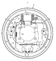
- a vehicular drum brake 1 includes a pair of arcuate brake shoes 3 and 3 arranged in a back plate 2 fixed to a vehicle body, and both brake shoes. One end of 3 and 3 is brought into contact with the piston of the wheel cylinder 4 (brake shoe operating member of the present invention), and the other end is brought into contact with the anchor 5 (brake shoe operating member of the present invention).
- the brake shoes 3 and 3 are expanded outward in the radial direction of the back plate 2, and the outer linings 3a and 3a are slid on a brake drum (not shown) to perform a braking action.
- one end of a parking lever 6 is pivotally supported by a support shaft 7, and the other end of the parking lever 6 has a brake cable 8 for pulling the parking lever 6.
- a brake cable 8 for pulling the parking lever 6.
- Each brake shoe 3 includes a web 3b whose middle portion is held by the back plate 2 by a shoe hold pin 9 and a shoe hold spring 10, and an arc-shaped rim 3c attached perpendicularly to the outer surface of the web 3b,
- the lining 3a is attached to the outer peripheral surface of the rim 3c.
- One end of the web 3b is supported by the wheel cylinder 4, the other end is supported by the anchor 5, and the back plate side surface of the rim 3c is supported by three ledge surfaces 2a formed on the back plate 2.
- shoe return springs 11 and 12 are stretched between the webs 3b and 3b on the inner side of the wheel cylinder 4 and the outer side of the anchor 5, respectively.
- an automatic brake clearance adjusting device 13 is disposed inside the shoe return spring 11 on the wheel cylinder side.
- the back plate 2 has an axle insertion hole 2b formed at the center, a first arc-shaped convex portion 2c concentric with the back plate 2 on the outer peripheral side, and a back plate 2 on the inner peripheral side of the first arc-shaped convex portion 2c.
- Concentric second arc-shaped convex portions 2d are formed so as to protrude to the inner side of the back plate 2, respectively.
- a wheel cylinder pedestal 2e is formed on the upper side and an anchor pedestal 2f is formed on the lower side so as to protrude from the inner side of the back plate 2.
- Shoe hold spring pedestal portions 2g and 2g for attaching the shoe hold spring 10 are projected to the inner side of the back plate 2 at the intermediate position in the circumferential direction of the back plate between the cylinder pedestal 2e and the anchor pedestal 2f. Is formed. Further, six ledge surfaces 2 a are formed on the outer peripheral side of the back plate so as to protrude from the inner side of the back plate 2.
- the wheel cylinder pedestal 2e, the anchor pedestal 2f, the shoe hold spring pedestals 2g, 2g, and the ledge surface 2a are formed of the first arcuate protrusion 2c and the second arcuate protrusion 2d.
- Each of the wheel cylinder pedestal 2e and the shoe hold spring pedestal 2g, 2g is formed so as to protrude from the inner side of the back plate 2h, 2i to the inner side of the back plate 2.
- the portion 2c and the second arcuate convex portion 2d are formed so as to protrude from the back plate inner side surfaces 2h and 2i, and a part of the anchor base portion 2f protrudes from the back plate inner side surface 2h of the first arcuate convex portion 2c. Is formed.
- the six ledge surfaces 2a are formed so as to protrude from the back plate inner side surface 2h of the first arcuate convex portion 2c.
- the entire surface of the back plate 2 can be reinforced uniformly and in a well-balanced manner by the first arc-shaped convex portion 2c and the second arc-shaped convex portion 2d.
- vibration of the back plate 2 can be suppressed, and brake noise can be suppressed.
- the first arc-shaped convex portion 2c and the second arc-shaped convex portion 2d are formed by protruding the back plate 2 to the inner side, there is no need to use a reinforcing plate as in the prior art.
- the back plate 2 can be reinforced, there is no possibility that the weight of the back plate 2 increases, and further, the workability can be improved and the cost can be reduced.
- the wheel cylinder pedestal 2e, the shoe hold spring pedestals 2g and 2g, the anchor pedestal 2f, the ledge surfaces 2a, the first arcuate protrusion 2c, and the second arcuate protrusion 2d are formed on the back plate 2. Therefore, the workability of the back plate 2 can be improved. Further, the wheel cylinder pedestal portion 2e and the shoe hold spring pedestal portions 2g and 2g partially protrude from the back plate inner side surfaces 2h and 2i of the first arc-shaped convex portion 2c and the second arc-shaped convex portion 2d.
- the anchor pedestal portion 2f is formed so that a part thereof protrudes from the back plate inner side surface 2h of the first arcuate convex portion 2c, and the plurality of ledge surfaces 2a are the back plate of the first arcuate convex portion 2c. Since it is formed so as to protrude from the inner side surface 2h, the strength of the back plate 2 can be efficiently ensured without increasing the size of the back plate 2.
- the vehicle drum brake of the present invention is not limited to the one applied to the leading / trading type drum brake as in the above-described embodiment, but any type such as a two-leading type or a duo servo type. It can also be applied to other drum brakes. Further, the number of the arc-shaped convex portions provided on the back plate is not limited to two provided as in the above-described embodiment, but may be one, or three or more may be provided. It can also be formed.
- SYMBOLS 1 Vehicle drum brake, 2 ... Back plate, 2a ... Ledge surface, 2b ... Axle insertion hole, 2c ... 1st circular arc-shaped convex part, 2d ... 2nd circular arc-shaped convex part, 2e ... Wheel cylinder base part, 2f ... pedestal part for anchor, 2g ... pedestal part for shoe hold spring, 2h, 2i ... back plate inner side face, 3 ... brake shoe, 3a ... lining, 3b ... web, 3c ... rim, 4 ... wheel cylinder, 5 ... anchor, DESCRIPTION OF SYMBOLS 6 ... Parking lever, 7 ... Support shaft, 8 ... Brake cable, 9 ... Shoe hold pin, 10 ... Shoe hold spring, 11, 12 ... Shoe return spring, 13 ... Automatic brake gap adjustment device
Landscapes
- Engineering & Computer Science (AREA)
- General Engineering & Computer Science (AREA)
- Mechanical Engineering (AREA)
- Braking Arrangements (AREA)
Abstract
コストを抑えながらバックプレートを充分に補強することができる車両用ドラムブレーキであって、バックプレート(2)は、ブレーキシュー(3,3)の両端部間に配置されるホイルシリンダ(4)とアンカー(5)とを固定するホイルシリンダ用台座部(2e)とアンカー用台座部(2f)と、ブレーキシュー(3)の拡縮を案内する複数のレッジ面(2a)とを、バックプレートの内部側に隆出させて形成すると共に、バックプレート(2)と同心の第1円弧状凸部(2c)と第2円弧状凸部(2d)とをバックプレート(2)の内部側に隆出させて形成する。
Description
本発明は、自動車や自動二輪車等の走行車両に用いられる車両用ドラムブレーキに関し、詳しくは、バックプレートの補強を図った車両用ドラムブレーキに関する。
従来、車両用ドラムブレーキは、バックプレートの内部にブレーキシューを拡縮自在に収容して形成され、バックプレートには、ブレーキシューの端部間に配置されるアンカーやホイルシリンダ等のブレーキシュー作動部材を固定する台座部と、前記ブレーキシューの拡縮を案内する複数のレッジ面とが、バックプレートの板材を内部側へ隆出させて形成されていた。
このバックプレートとして、制動時に振動してブレーキ鳴きを発生させないように、補強されたものがあり、バックプレートに補強板を重ね合わせたもの(例えば、特許文献1参照)や、バックプレートに補強板を埋め込んだもの(例えば、特許文献2参照。)や、負荷を受けやすいアンカーを取り付ける台座部に補強用の凸部をバックプレートの板材を内部側へ隆出させて形成させたもの(例えば、特許文献3参照。)があった。
しかし、上述の特許文献1のものでは、バックプレートに補強板を絞り加工により結合させ、また、特許文献2のものでは、バックプレートの加圧鋳造時に補強板を埋め込んで結合させることから、バックプレートと別物品の補強板を用いなければならないと共に、結合に手間が掛かることからコストが嵩んでいた。また、特許文献3のものでは、アンカーを取り付ける台座部の部分の補強は成されているが、その他の部分の補強が不十分であった。
そこで本発明は、コストを抑えながらバックプレートを充分に補強することができる車両用ドラムブレーキを提供することを目的としている。
上記目的を達成するため、本発明の車両用ドラムブレーキは、バックプレートの内部に一対のブレーキシューが拡縮自在に収容され、前記バックプレートに、前記ブレーキシューの両端部間にそれぞれ配置されるブレーキシュー作動部材を固定する台座部と、前記ブレーキシューの拡縮を案内する複数のレッジ面とを、前記バックプレートの内部側に隆出させて形成した車両用ドラムブレーキにおいて、前記バックプレートに、前記バックプレートと同心の円弧状凸部を隆出させて形成したことを特徴としている。
また、前記円弧状凸部は、前記バックプレートの内部側に隆出させて形成されると好ましい。さらに、前記台座部と前記レッジ面とは、前記円弧状凸部よりも前記バックプレートの内部側に突出して形成されると共に、前記台座部と前記レッジ面の少なくとも一部は、前記円弧状凸部から、前記バックプレートの内部側に突出して形成されていると好適である。また、前記円弧状凸部は、バックプレートの外周側に形成される第1円弧状凸部と、該第1円弧状凸部よりバックプレートの内周側に形成される第2円弧状凸部とを備えていると好ましい。
本発明の車両用ドラムブレーキによれば、バックプレートは、バックプレートと同心の円弧状凸部で補強されることから、バックプレートを全周に亘って略均一にバランス良く補強することができ、制動時にバックプレートの振動を抑え、ブレーキ鳴きを抑制することができる。また、補強板を用いることなくバックプレートを補強することができることから、バックプレートの重量が嵩む虞がなく、また、加工性の向上を図ることができるとともに、コストを抑えることができる。
さらに、円弧状凸部は、前記台座部及び前記レッジ面と同様に、バックプレートの内部側に隆出させることにより、バックプレートを大型化させることなく補強することができ、さらに、バックプレートの加工性を向上させることができる。また、台座部とレッジ面とは、円弧状凸部よりもバックプレートの内部側に突出して形成されると共に、台座部とレッジ面の少なくとも一部は、円弧状凸部から、バックプレートの内部側に突出して形成されることから、バックプレートを大型化させることなく、効率的に補強することができる。さらに、円弧状凸部は、バックプレートの外周側に形成される第1円弧状凸部と、該第1円弧状凸部よりバックプレートの内周側に形成される第2円弧状凸部とを備えていることから、バックプレートを充分に補強することができる。
図1乃至図3は本発明の一形態例を示し、車両用ドラムブレーキ1は、車体に固設されるバックプレート2の内部に弓形の一対のブレーキシュー3,3を配置し、両ブレーキシュー3,3の一端をホイルシリンダ4(本発明のブレーキシュー作動部材)のピストンに、他端をアンカー5(本発明のブレーキシュー作動部材)にそれぞれ当接させている。
この車両用ドラムブレーキ1は、ブレーキシュー3,3をバックプレート2の半径方向外側へ拡開して、外周のライニング3a,3aをブレーキドラム(図示せず)に摺動させて制動作用を行うリーディング・トレーディングタイプで、一方のブレーキシュー3には、パーキングレバー6の一端が支軸7にて枢支され、該パーキングレバー6の他端には、パーキングレバー6を牽引するためのブレーキケーブル8が連結されている。
各ブレーキシュー3は、中間部をシューホールドピン9とシューホールドスプリング10とによってバックプレート2に弾持されるウェブ3bと、該ウェブ3bの外面に直交して取り付けられる円弧状のリム3cと、該リム3cの外周面に貼着される前記ライニング3aとから成っている。ウェブ3bは、一端部がホイルシリンダ4に支承され、他端部がアンカー5に支承されるとともに、リム3cのバックプレート側面が、バックプレート2に形成した3個のレッジ面2aに支承されている。また、両ウェブ3b,3bの間には、ホイルシリンダ4の内側とアンカー5の外側とにシュー戻しばね11,12がそれぞれ張設されていて、双方のブレーキシュー3,3を常時縮径方向へ付勢しており、更に、ホイルシリンダ側のシュー戻しばね11の内側には、制動間隙自動調整装置13が配置されている。
バックプレート2は、中央にアクスル挿通孔2bが形成され、外周側にバックプレート2と同心の第1円弧状凸部2cが、該第1円弧状凸部2cよりも内周側にバックプレート2と同心の第2円弧状凸部2dがそれぞれバックプレート2の内部側に隆出させて形成されている。さらに、アクスル挿通孔2bの図1において上部側にはホイルシリンダ用台座部2eが、下部側にはアンカー用台座部2fがバックプレート2の内部側に隆出させてそれぞれ形成されると共に、ホイルシリンダ用台座部2eとアンカー用台座部2fのバックプレート周方向中間位置には、シューホールドスプリング10を取り付けるシューホールドスプリング用台座部2g,2gが、バックプレート2の内部側に隆出させてそれぞれ形成されている。さらに、バックプレート外周側には、6個の前記レッジ面2aが、バックプレート2の内部側に隆出させてそれぞれ形成されている。
また、ホイルシリンダ用台座部2eと、アンカー用台座部2fと、シューホールドスプリング用台座部2g,2gと、レッジ面2aとは、第1円弧状凸部2c及び第2円弧状凸部2dのバックプレート内部側面2h,2iよりもバックプレート2の内部側にそれぞれ突出して形成され、ホイルシリンダ用台座部2eとシューホールドスプリング用台座部2g,2gとは、その一部が第1円弧状凸部2cと第2円弧状凸部2dのバックプレート内部側面2h,2iから突出して形成され、アンカー用台座部2fは、その一部が第1円弧状凸部2cのバックプレート内部側面2hから突出して形成されている。また、6個のレッジ面2aは第1円弧状凸部2cのバックプレート内部側面2hから突出して形成されている。
上述のように形成された車両用ドラムブレーキ1では、第1円弧状凸部2cと第2円弧状凸部2dとによって、バックプレート2の全面を均一にバランス良く補強することができることから、制動時にバックプレート2の振動を抑えることができ、ブレーキ鳴きを抑制することができる。また、第1円弧状凸部2cと第2円弧状凸部2dとは、バックプレート2を内部側に隆出させて形成されていることから、従来のように、補強板を用いることがなくバックプレート2を補強でき、バックプレート2の重量が嵩む虞がなく、さらに、加工性の向上を図るとともにコストを抑えることができる。また、ホイルシリンダ用台座部2e、シューホールドスプリング用台座部2g,2g、アンカー用台座部2f、各レッジ面2a、第1円弧状凸部2c,第2円弧状凸部2dは、バックプレート2の内部側に突出させていることから、バックプレート2の加工性を向上させることができる。さらに、ホイルシリンダ用台座部2eとシューホールドスプリング用台座部2g,2gとは、その一部が第1円弧状凸部2cと第2円弧状凸部2dのバックプレート内部側面2h,2iから突出して形成され、アンカー用台座部2fは、その一部が第1円弧状凸部2cのバックプレート内部側面2hから突出して形成され、複数のレッジ面2aは第1円弧状凸部2cのバックプレート内部側面2hから突出して形成されていることから、バックプレート2を大型化させることなく効率的にバックプレート2の強度を確保することができる。
尚、本発明の車両用ドラムブレーキは、上述の形態例のようにリーディング・トレーディングタイプのドラムブレーキに適用されるものに限らず、2リーディングタイプや、デュオサーボタイプのもの等、どのようなタイプのドラムブレーキにも適用することができる。さらに、バックプレートに設ける円弧状凸部は、上述の形態例のように2本設けるものに限らず、1本でも良く、また、3本以上設けることもでき、バックプレートの外部側に隆出させて形成することもできる。
1…車両用ドラムブレーキ、2…バックプレート、2a…レッジ面、2b…アクスル挿通孔、2c…第1円弧状凸部、2d…第2円弧状凸部、2e…ホイルシリンダ用台座部、2f…アンカー用台座部、2g…シューホールドスプリング用台座部、2h,2i…バックプレート内部側面、3…ブレーキシュー、3a…ライニング、3b…ウェブ、3c…リム、4…ホイルシリンダ、5…アンカー、6…パーキングレバー、7…支軸、8…ブレーキケーブル、9…シューホールドピン、10…シューホールドスプリング、11,12…シュー戻しばね、13…制動間隙自動調整装置
Claims (4)
- バックプレートの内部に一対のブレーキシューが拡縮自在に収容され、前記バックプレートに、前記ブレーキシューの両端部間にそれぞれ配置されるブレーキシュー作動部材を固定する台座部と、前記ブレーキシューの拡縮を案内する複数のレッジ面とを、前記バックプレートの内部側に隆出させて形成した車両用ドラムブレーキにおいて、前記バックプレートに、前記バックプレートと同心の円弧状凸部を隆出させて形成したことを特徴とした車両用ドラムブレーキ。
- 前記円弧状凸部は、前記バックプレートの内部側に隆出させて形成されていることを特徴とする請求項1記載の車両用ドラムブレーキ。
- 前記台座部と前記レッジ面とは、前記円弧状凸部よりも前記バックプレートの内部側に突出して形成されると共に、前記台座部と前記レッジ面の少なくとも一部は、前記円弧状凸部から、前記バックプレートの内部側に突出して形成されていることを特徴とする請求項2記載の車両用ドラムブレーキ。
- 前記円弧状凸部は、バックプレートの外周側に形成される第1円弧状凸部と、該第1円弧状凸部よりバックプレートの内周側に形成される第2円弧状凸部とを備えていることを特徴とする請求項1乃至3のいずれか1項記載の車両用ドラムブレーキ。
Priority Applications (1)
| Application Number | Priority Date | Filing Date | Title |
|---|---|---|---|
| JP2015543811A JP6349323B2 (ja) | 2013-10-21 | 2014-10-16 | 車両用ドラムブレーキ |
Applications Claiming Priority (2)
| Application Number | Priority Date | Filing Date | Title |
|---|---|---|---|
| JP2013218508 | 2013-10-21 | ||
| JP2013-218508 | 2013-10-21 |
Publications (1)
| Publication Number | Publication Date |
|---|---|
| WO2015060180A1 true WO2015060180A1 (ja) | 2015-04-30 |
Family
ID=52992779
Family Applications (1)
| Application Number | Title | Priority Date | Filing Date |
|---|---|---|---|
| PCT/JP2014/077498 Ceased WO2015060180A1 (ja) | 2013-10-21 | 2014-10-16 | 車両用ドラムブレーキ |
Country Status (2)
| Country | Link |
|---|---|
| JP (1) | JP6349323B2 (ja) |
| WO (1) | WO2015060180A1 (ja) |
Citations (2)
| Publication number | Priority date | Publication date | Assignee | Title |
|---|---|---|---|---|
| JPS57130027U (ja) * | 1981-02-06 | 1982-08-13 | ||
| JP2005344833A (ja) * | 2004-06-03 | 2005-12-15 | Nissin Kogyo Co Ltd | 車両用ドラムブレーキのバックプレート |
Family Cites Families (2)
| Publication number | Priority date | Publication date | Assignee | Title |
|---|---|---|---|---|
| DE1149998B (de) * | 1956-11-24 | 1963-06-06 | Rockwell Federn | Innenbackenbremse, insbesondere fuer Kraftfahrzeuge |
| DE19622520C1 (de) * | 1996-06-05 | 1997-11-27 | Ebern Fahrzeugtech Gmbh | Innenbacken-Trommelbremse |
-
2014
- 2014-10-16 JP JP2015543811A patent/JP6349323B2/ja active Active
- 2014-10-16 WO PCT/JP2014/077498 patent/WO2015060180A1/ja not_active Ceased
Patent Citations (2)
| Publication number | Priority date | Publication date | Assignee | Title |
|---|---|---|---|---|
| JPS57130027U (ja) * | 1981-02-06 | 1982-08-13 | ||
| JP2005344833A (ja) * | 2004-06-03 | 2005-12-15 | Nissin Kogyo Co Ltd | 車両用ドラムブレーキのバックプレート |
Also Published As
| Publication number | Publication date |
|---|---|
| JP6349323B2 (ja) | 2018-06-27 |
| JPWO2015060180A1 (ja) | 2017-03-09 |
Similar Documents
| Publication | Publication Date | Title |
|---|---|---|
| JP5844630B2 (ja) | ドラムブレーキ式電動駐車ブレーキ装置 | |
| JP2006010079A5 (ja) | ||
| KR101543128B1 (ko) | 주차 브레이크 통합형 이종재질 디스크 브레이크 장치 | |
| JP2015028377A (ja) | 鉄道車両用ディスクブレーキパッド | |
| JP2014098407A (ja) | ディスクブレーキ用パッド | |
| JP6349323B2 (ja) | 車両用ドラムブレーキ | |
| ITMI20100813A1 (it) | Dispositivo di frenatura a disco per veicoli | |
| JP5363388B2 (ja) | ドラムブレーキのブレーキパネル構造 | |
| JP2018035828A (ja) | 車両用ドラムブレーキ | |
| JPH0726583Y2 (ja) | ドラムブレーキ用ダンピング装置 | |
| JPH11287266A (ja) | ディスクブレーキ | |
| JP6761275B2 (ja) | 車両用ドラムブレーキ | |
| JP2014156914A (ja) | 車両用ドラムブレーキのブレーキシュー係合部構造 | |
| JP2005344833A (ja) | 車両用ドラムブレーキのバックプレート | |
| JP5087645B2 (ja) | ピンレールキャリパを有するディスクブレーキ | |
| JP5271436B2 (ja) | 車両用ドラムブレーキ | |
| JPH017869Y2 (ja) | ||
| JP6460852B2 (ja) | 車両用ドラムブレーキ | |
| KR101351342B1 (ko) | 드럼 브레이크 | |
| JP4998327B2 (ja) | ディスクロータの取付構造 | |
| JP6644532B2 (ja) | 車両用ドラムブレーキ | |
| JP5653168B2 (ja) | デュオサーボ式ドラムブレーキ | |
| JP2011247422A (ja) | ディスクブレーキのためのブレーキパッド | |
| JP6115089B2 (ja) | ディスクブレーキ用パッド | |
| KR20120030625A (ko) | 드럼 브레이크 |
Legal Events
| Date | Code | Title | Description |
|---|---|---|---|
| 121 | Ep: the epo has been informed by wipo that ep was designated in this application |
Ref document number: 14855518 Country of ref document: EP Kind code of ref document: A1 |
|
| ENP | Entry into the national phase |
Ref document number: 2015543811 Country of ref document: JP Kind code of ref document: A |
|
| NENP | Non-entry into the national phase |
Ref country code: DE |
|
| 122 | Ep: pct application non-entry in european phase |
Ref document number: 14855518 Country of ref document: EP Kind code of ref document: A1 |