WO2015053220A1 - Dynamometer system - Google Patents
Dynamometer system Download PDFInfo
- Publication number
- WO2015053220A1 WO2015053220A1 PCT/JP2014/076691 JP2014076691W WO2015053220A1 WO 2015053220 A1 WO2015053220 A1 WO 2015053220A1 JP 2014076691 W JP2014076691 W JP 2014076691W WO 2015053220 A1 WO2015053220 A1 WO 2015053220A1
- Authority
- WO
- WIPO (PCT)
- Prior art keywords
- output
- dynamometer
- control
- detection model
- torque
- Prior art date
Links
Images


Classifications
-
- G—PHYSICS
- G01—MEASURING; TESTING
- G01L—MEASURING FORCE, STRESS, TORQUE, WORK, MECHANICAL POWER, MECHANICAL EFFICIENCY, OR FLUID PRESSURE
- G01L3/00—Measuring torque, work, mechanical power, or mechanical efficiency, in general
- G01L3/16—Rotary-absorption dynamometers, e.g. of brake type
-
- G—PHYSICS
- G01—MEASURING; TESTING
- G01M—TESTING STATIC OR DYNAMIC BALANCE OF MACHINES OR STRUCTURES; TESTING OF STRUCTURES OR APPARATUS, NOT OTHERWISE PROVIDED FOR
- G01M15/00—Testing of engines
- G01M15/02—Details or accessories of testing apparatus
-
- G—PHYSICS
- G01—MEASURING; TESTING
- G01M—TESTING STATIC OR DYNAMIC BALANCE OF MACHINES OR STRUCTURES; TESTING OF STRUCTURES OR APPARATUS, NOT OTHERWISE PROVIDED FOR
- G01M15/00—Testing of engines
- G01M15/04—Testing internal-combustion engines
- G01M15/05—Testing internal-combustion engines by combined monitoring of two or more different engine parameters
Definitions
- the present invention relates to a dynamometer system. More specifically, the present invention relates to a dynamometer system for connecting a dynamometer as a power absorber to a specimen equipped with an engine and measuring various characteristics of the engine.
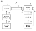
- FIG. 26 is a diagram illustrating a configuration of the dynamometer system 100.
- the dynamometer system 100 includes a specimen W composed of the engine E and its output shaft S, a dynamometer D connected to the output shaft S of the specimen W as a power absorber, and a throttle actuator 110.
- Engine controller 120 for controlling E
- dynamo controller 140 for controlling dynamometer D via inverter 130
- encoder 150 for detecting the rotational speed of the output shaft of dynamometer D
- output shaft S of specimen W
- a shaft torque sensor 160 for detecting a shaft torque (torsional torque) of a coupling portion between the dynamometer D and the output shaft of the dynamometer D.
- mechanical elements such as a clutch, a transmission, and a propeller shaft are collectively shown as an output shaft S in a simplified manner.
- the engine controller 120 controls the output of the engine E in a predetermined manner for each test item, and the dynamo controller 140 controls the rotational speed of the dynamometer D based on the outputs of the encoder 150 and the shaft torque sensor 160. And torque are controlled (see, for example, Patent Documents 1 and 2).
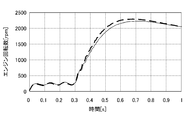
- FIG. 27 is a diagram illustrating a change in the number of revolutions when the engine is started when the conventional system 100 realizes the no-load state. More specifically, it is a diagram showing a change in the number of revolutions at the time of starting the engine when the shaft torque command value input to the dynamo controller 140 is set to 0 so that no torsional torque is generated in the conventional system 100.
- the measurement result by the system 100 that is, the number of rotations measured by the encoder 150 is indicated by a thin solid line.
- the rotational speed measured with the engine E and the output shaft S disconnected and the engine E in a no-load state that is, an ideal value at the time of no-load control is indicated by a thick broken line.
- the shaft torque sensor 160 of the output shaft S is simply controlled by setting the shaft torque command value to 0 [Nm] and the detected value of the shaft torque sensor to 0 [Nm].
- the inertia of the portion on the engine E side must be borne by the engine E, the engine speed at the time of starting becomes smaller than an ideal value corresponding to the no-load state.
- the inertia of the output shaft S can be borne by the dynamometer D if the position of the shaft torque sensor 160 is closer to the crankshaft side of the engine E.
- the closer the shaft torque sensor 160 is to the engine E the more easily the heat of the engine E is transmitted, so the influence of the change in the measured value due to the temperature drift increases.
- the closer the shaft torque sensor 160 is to the engine E the easier the vibration of the engine E is transmitted, and the measurement accuracy decreases.
- the position of the shaft torque sensor 160 is preferably closer to the dynamometer D than the engine E. Therefore, the above problem becomes significant.
- Patent Document 3 discloses a technique for realizing a no-load state at the time of engine start by feedforward control.
- a torque current command value that realizes the dynamo rotation speed measured at the time of starting the engine in advance is output in accordance with the timing of engine start (that is, the ignition signal of the first engine explosion).
- the rotational speed at the time of starting the engine alone (corresponding to the thick broken line in FIG. 27) is measured, or the rotation measured at the time of engine starting is measured. Therefore, it is necessary to record the torque current command value when controlling the rotational speed of the dynamo so as to realize the number, or to output the torque current command value recorded at an appropriate timing.
- An object of the present invention is to provide a dynamometer control device for a dynamometer system that can accurately reproduce a no-load state when a specimen is started.
- a dynamometer system (for example, a dynamometer system 1 described later) is connected via a specimen (for example, an engine E described later) that generates power and an intermediate coupling body (for example, a shaft S described later).
- a dynamometer (for example, a dynamometer D described later), a torque detector (for example, a shaft torque sensor 61 described later) for detecting the torsional torque of the intermediate combined body, and a rotational speed detection for detecting the rotational speed of the dynamometer (For example, an encoder 62 described later) and an inverter (for example, an inverter 3 described later) for supplying electric power to the dynamometer.
- the present invention provides a dynamo control device for a dynamometer system that generates a torque current command to the inverter based on detection signals of the torque detector and the rotation speed detector (for example, dynamo control described later).
- Devices 6a, 6b, 6c, 6d, 6e, 6f, 6g which are external inputs corresponding to torque generated in the specimen (for example, external input w described later) and control inputs corresponding to the torque current command.
- a generalized plant for example, a generalization described later that outputs a predetermined observation output (for example, observation outputs y1, y2 described later) and a controlled variable (for example, a controlled variable z described later) from (for example, a control input u described later).
- a predetermined observation output for example, observation outputs y1, y2 described later
- a controlled variable for example, a controlled variable z described later
- H ⁇ control or ⁇ design method so as to reduce the response from the external input to the controlled variable.
- controller designed by the control system design methods (e.g., controller Gc 1, Gc2 below) including.
- the generalized plant includes a dynamic characteristic model (for example, a dynamic characteristic model 7 described later) that identifies the characteristics of the dynamometer system so as to output the angular acceleration of the specimen from the external input and the control input.
- the control amount of the generalized plant is a weight function having an integral characteristic in the difference between the angular acceleration of the single specimen calculated based on the external input and the angular acceleration of the specimen calculated by the dynamic characteristic model. Is a signal multiplied by.
- the dynamic characteristic model of the generalized plant includes an inverter model (for example, an inverter model P12 described later) that identifies the characteristics of the inverter, the specimen, the intermediate coupling body, and the dynamometer.
- a machine model for example, machine models P4 to P9 described later
- a torque detection model for example, torque detection model P10 that is described later
- a rotation speed detection model for example, a rotation speed detection model P11 described later
- an output obtained by multiplying the control input by a predetermined proportional gain is used as an input to the inverter model, and an output of an integrator provided at the output terminal of the torque detection model is a first observation output. It is preferable that the output of the proportional gain provided at the output end of the rotation speed detection model is the second observation output.
- control input is an input to the inverter model, the output of the rotation speed detection model multiplied by a predetermined proportional gain, and the output of an integrator provided at the output terminal of the torque detection model, It is preferable that an output obtained by multiplying the difference by a predetermined proportional gain is a first observation output, and an output of the torque detection model is a second observation output.
- the difference between the output of the rotation speed detection model multiplied by the predetermined proportional gain and the output of the integrator provided at the output terminal of the torque detection model is obtained by multiplying the predetermined proportional gain. It is preferable that an output obtained by combining the output and the control input is an input to the inverter model, and an output of the torque detection model is an observation output.
- control input is an input to the inverter model, the output of the rotation speed detection model multiplied by a predetermined proportional gain, and the output of an integrator provided at the output terminal of the torque detection model It is preferable that an output obtained by multiplying the difference by a predetermined proportional gain is an observation output.
- control input is an input to the inverter model, the output of the rotation speed detection model multiplied by a predetermined proportional gain, and the output of an integrator provided at the output terminal of the torque detection model
- an output obtained by multiplying the difference by a predetermined proportional gain is used as a first observation output
- an output of a high-pass filter provided at the output terminal of the torque detection model is used as a second observation output.
- an output obtained by multiplying the control input by a predetermined proportional gain is used as an input to the inverter model, an output of the torque detection model is used as a first observation output, and a predetermined proportional gain is multiplied.
- the difference between the output of the rotation speed detection model and the output of the torque detection model is preferably used as the second observation output.
- a specimen, an intermediate coupling, and a dynamometer are mechanically connected, and a dynamometer system is configured by providing an inverter, a torque detector, and a rotational speed detector.
- a design method called H ⁇ control or ⁇ design method More specifically, a generalized plant including a dynamic characteristic model that identifies the characteristics of the dynamometer system is defined, and the response from the external input corresponding to the torque generated in the specimen to a predetermined control amount is reduced.
- a controller is designed for the dynamo controller.
- the control amount of the generalized plant is the angular acceleration of the single specimen calculated based on the external input (that is, the angle of the specimen when it is assumed that the specimen, the intermediate coupling body, and the dynamometer are separated). Acceleration) and the angular acceleration of the specimen calculated by the dynamic characteristic model.
- a torque current command is issued so that the inertia of the intermediate combination is compensated by the dynamometer in the system in which the specimen and the dynamometer that generate power are connected by the intermediate combination.
- a dynamo control device to be generated can be constructed. In other words, a dynamo control device capable of realizing a no-load state as if the intermediate joint is not connected as viewed from the specimen, even though the specimen and the dynamometer are connected by the intermediate joint. Can be built.
- the intermediate coupling body is composed of various mechanical elements such as a shaft, a clutch, and a transmission, and the rigidity varies depending on the vehicle type.
- the higher the rigidity of the intermediate coupling body the higher the mechanical resonance point of the system. .
- the higher the mechanical resonance point the greater the influence of response delays of the torque detector, the rotational speed detector, the inverter, and the like, so that resonance suppression becomes more difficult.
- the present invention by designing with H ⁇ control or ⁇ design method, it is possible to construct a dynamo control device having a high resonance suppression effect in addition to the inertia compensation effect of the above-described intermediate coupled body.
- a dynamic characteristic model corresponding to a nominal plant is composed of a mechanical model, an inverter model, a torque detection model, and a rotation speed detection model that identify the characteristics of a three-inertia system, and is close to an actual system.
- a predetermined proportional gain is provided between the control input and the inverter model, an integrator is provided between the torque detection model and the first observation output, and the rotational speed A proportional gain is provided between the detection model and the second observation output.
- These integrators and proportional gains are control elements required when performing the inertia compensation control of the intermediate combination as described above.
- the essential control elements can be separated from the two controllers that are numerically derived by H ⁇ control or ⁇ design method. Evaluation of the derived controller is facilitated.
- the inertia compensation amount and the control response can be adjusted without changing the characteristics of the two controllers once derived. In other words, it is not necessary to repeatedly perform H ⁇ control and ⁇ design method in order to construct a dynamo control device having desired characteristics.
- an integrator and two proportional gains are provided between the control input, the torque detection model, the rotation speed detection model, and the inverter model.
- This makes it possible to separate the essential control elements of the inertia compensation control from the derived controller, as in the invention of (3) above, thereby facilitating the evaluation of the controller and the inertia compensation amount without changing the characteristics of the controller. And control responsiveness can be adjusted.
- the number of derived controllers can be reduced to one by setting the observation output of the generalized plant to one.
- the inertia compensation control is mainly required at the time of starting the specimen. However, by setting the number of controllers that perform the inertia compensation control to one, it is possible to change the control mode from the inertia compensation control to another. Press processing becomes easy.
- an integrator and two proportional gains are provided between the rotational speed detection model and the torque detection model and the second observation output, and the torque detection model and the first observation are further provided.
- a high pass filter is provided between the output and the output.
- a proportional gain is provided between the control input and the inverter model, and an integrator and a proportionality are provided between the torque detection model and the rotation speed detection model and the second observation output.
- Provide gain This makes it possible to separate the essential control elements of the inertia compensation control from the derived controller, as in the invention of (3) above, thereby facilitating the evaluation of the controller and the inertia compensation amount without changing the characteristics of the controller. And control responsiveness can be adjusted.
- FIG. 3 is a Bode diagram of the controller according to the first embodiment.
- FIG. 10 is a Bode diagram of controllers Gc1 and Gc2 according to the third embodiment.
- FIG. 10 is a Bode diagram of controllers Gc1 and Gc2 of Example 6. It is a figure which shows the specific structure of the generalized plant of Example 7. FIG. It is a figure which shows the specific structure of the dynamo control apparatus of Example 7. FIG. FIG. 10 is a Bode diagram of controllers Gc1 and Gc2 of Example 7. It is a figure which shows the structure of the conventional dynamometer system. It is a figure which shows the rotation speed change at the time of engine starting in the case of implement
- FIG. 1 is a diagram illustrating a configuration of a dynamometer system 1 in which a dynamo control device 6 according to the present embodiment is used.
- the dynamometer system 1 includes an engine E as a specimen, a dynamometer D connected to the engine E via a substantially rod-shaped shaft S, and an engine control device 5 that controls the engine E via a throttle actuator 2.
- An inverter 3 for supplying power to the dynamometer D, a dynamometer control device 6 for controlling the dynamometer D via the inverter 3, an axis torque sensor 61 for detecting the torsional torque of the shaft S, and an output shaft of the dynamometer D And an encoder 62 for detecting the rotational speed of the SD.
- the shaft torque sensor 61 detects a torsion torque acting on a portion of the shaft S extending from the engine E to the dynamometer D closer to the dynamometer D than the engine E from, for example, a distortion amount of the shaft S in the twist direction. A signal substantially proportional to the value is transmitted to the dynamo controller 6.
- the engine control device 5 controls the output of the engine E in a predetermined manner after starting the engine E at a predetermined timing.
- the dynamo control device 6 corresponds to a torque value to be generated by the dynamometer D based on detection signals of the shaft torque sensor 61 and the encoder 62 so that the power generated by the engine E is absorbed in a predetermined manner.
- a torque current command is generated and input to the inverter 3.
- the dynamo control device 6 defines a generalized plant P that outputs a predetermined control amount z and an observation output y from a predetermined external input w and control input u as shown in FIG. What is configured by mounting a controller K designed by a robust control system design method called H ⁇ control or ⁇ design method so as to reduce the response from the input w to the control amount z to an electronic computer is used. .
- Generalized plant P is used in the robust control system design method described above, and is composed of a dynamic characteristic model to be controlled and a weight function that defines control specifications.
- a controller K that achieves a desired control purpose from the generalized plant P by these H ⁇ control and ⁇ design method, for example, written by Liu Yasushi, “Linear Robust Control”, Corona, 2002, edited by Kenzo Nonami, Hidekazu Nishimura, Mitsuo Hirata, “Control System Design with MATLAB”, Tokyo Denki University Press, 1998, etc., so detailed explanation is omitted here. To do.
- specific configurations of the generalized plant P and the dynamo control device 6 derived thereby will be described as Examples 1 to 7.
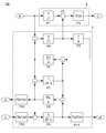
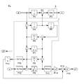
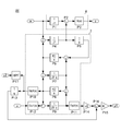
- FIG. 3 is a diagram illustrating a specific configuration of the generalized plant Pa according to the first embodiment.
- the input signal w indicates an external input and corresponds to the engine torque generated in the engine.
- the input signal u indicates a control input output from a controller (not shown) and corresponds to a torque current command input to the inverter.
- the output signal z indicates a control amount and corresponds to a difference value that is desired to be reduced by H ⁇ control or ⁇ design method. The specific contents of this difference value will be described in detail later.
- Two output signals y1 and y2 indicate first and second observation outputs input to a controller (not shown), and correspond to the detected value of the shaft torque sensor and the detected value of the encoder, respectively.
- the generalized plant Pa includes a dynamic characteristic model 7 that identifies the characteristics of the dynamometer system 1 shown in FIG. 1 so as to output the angular acceleration of the engine from the external input w and the control input u, and the external input w and the dynamic characteristic model 7.
- a control amount calculation unit 8 that calculates the control amount z based on the output of.
- the dynamic characteristic model 7 includes mechanical models P4 to P9 that identify characteristics of a three-inertia system configured by connecting an engine, a shaft, and a dynamometer, and an axial torque detection model that identifies axial torque detection characteristics by an axial torque sensor.
- P10 a rotational speed detection model P11 that identifies the rotational speed detection characteristic of the dynamometer by the encoder, and P12 that identifies the torque current control characteristic by the inverter.
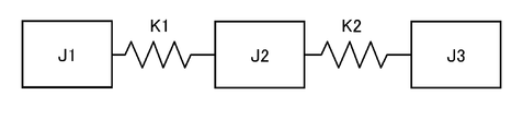
- the configuration of the mechanical system of the dynamometer system 1 can be approximated by a three-inertia system model configured by connecting three rigid bodies each having a unique moment of inertia as shown in FIG. 4 with two spring elements.
- "J1" is equivalent to the moment of inertia of the engine [kgm 2]
- "J2” corresponds to the moment of inertia of the shaft [kgm 2]
- "J3" the dynamometer inertia It corresponds to a moment [kgm 2 ].
- K1” corresponds to the spring stiffness [Nm / rad] between the engine and the shaft
- K2 corresponds to the spring stiffness [Nm / rad] between the shaft and the dynamometer.
- the transfer function Gy1 (s) of the shaft torque detection model P10, the transfer function Gy2 (s) of the rotational speed detection model P11, and the transfer function Gu1 (s) of the inverter model P12 are respectively predetermined by system identification. Used.
- the control amount calculation unit 8 calculates the dynamic characteristic model 7 described above from the angular acceleration of the engine alone (output of the block P1) obtained by multiplying the external input w corresponding to the engine torque by the reciprocal of the moment of inertia J1 of the engine alone.
- the difference value obtained by subtracting the angular acceleration of the engine (the output of the block P4) calculated by the above is calculated, and the control amount z is calculated by multiplying the difference value by a predetermined weight function G (s).
- the weight function G (s) for example, one having an integral characteristic is used.
- the angular acceleration of the engine alone and the angular acceleration of the engine calculated from the dynamic characteristic model and the difference value are set as the control amount z, and the response from the external input w to the control amount z is reduced.
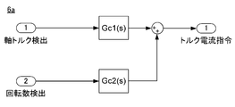
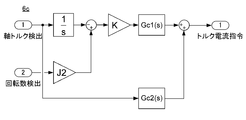
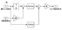
- FIG. 5 is a diagram illustrating a specific configuration of the dynamo control device 6a according to the first embodiment.
- this dynamo control device 6a two controllers Gc1 and Gc2 derived from the generalized plant Pa are used.
- the controller Gc1 is derived corresponding to the first observation output y1
- the controller Gc2 is derived corresponding to the second observation output y2.
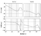
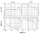
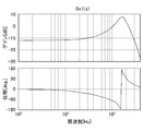
- FIG. 6 is a Bode diagram of the controllers Gc1 and Gc2 according to the first embodiment.
- the upper part of FIG. 6 shows gain characteristics, and the lower part shows phase characteristics.
- an integral characteristic is recognized in the low range of the controller Gc1
- a proportional characteristic is recognized in the low range of the controller Gc2.
- These integral characteristics and proportional characteristics are necessary control elements for compensating the shaft inertia with the dynamometer.
- the gain decreases at a predetermined mechanical resonance point.
- the shaft inertia compensation effect for compensating the shaft inertia so as to be in a no-load state as seen from the engine, and the resonance suppression for suppressing the mechanical resonance point. It became clear that both the effects were played simultaneously.
- the response of the shaft inertia compensation control can be generally evaluated by how much the controllers Gc1 and Gc2 have integral characteristics and proportional characteristics.
- the controllers Gc1 and Gc2 in FIG. 6 can be evaluated as having a response of about 10 Hz.
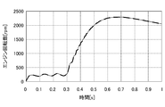
- FIG. 7 is a diagram showing changes in the engine speed when the engine is started in the dynamometer system using the dynamo control device of FIG.
- the measurement result by the system using the dynamo control device of FIG. 6 is shown by a thin solid line.
- the result of measurement when the engine and the shaft are separated and the engine is actually in a no-load state, that is, an ideal value at the time of shaft inertia compensation is indicated by a thick broken line.
- the thin solid line and the thick broken line almost coincide.
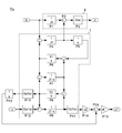
- FIG. 8 is a diagram illustrating a specific configuration of the generalized plant Pb of the second embodiment.
- the configuration different from the generalized plant Pa of Example 1 in FIG. 3 will be described.
- the same components as those in the generalized plant Pa of the first embodiment are denoted by the same reference numerals, and detailed description thereof is omitted.
- the integral characteristic and the proportional characteristic appear as a result in the controller derived so as to obtain the shaft inertia compensation effect.
- a generalized plant Pb in which these control elements are included in advance is used in order to separate the control elements necessary for obtaining the shaft inertia compensation effect from the controller.
- an integrator P13 and two gain blocks P14 and P15 are added to the generalized plant Pa of the first embodiment. More specifically, in the second embodiment, the output of the integrator P13 provided at the output end of the torque detection model P10 is defined as the first observation output y1, and the inertia of the shaft provided at the output end of the rotation speed detection model P11 is used. The output of the gain block P14 of the moment J2 is set as the second observation output y2. In the second embodiment, an output obtained by multiplying the control input u by a predetermined proportional gain K, which is a measure of control response, is used as an input to the inverter model P12.
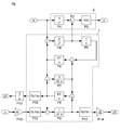
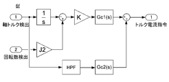
- FIG. 9 is a diagram illustrating a specific configuration of the dynamo control device 6b according to the second embodiment.
- two controllers Gc1 (s) and Gc2 (s) derived from the generalized plant Pb are used.
- the controller Gc1 is derived corresponding to the first observation output y1
- the controller Gc2 is derived corresponding to the second observation output y2.
- the characteristics of the integrator and the proportional gain are separated from the derived controllers Gc1 and Gc2.
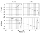
- FIG. 10 is a Bode diagram of the controllers Gc1 and Gc2 of the second embodiment.
- the upper part of FIG. 10 shows gain characteristics, and the lower part shows phase characteristics.
- controllers Gc1 and Gc2 having a proportional characteristic of the same gain in the low frequency range are derived.
- both the controllers Gc1 and Gc2 have the same gain in the low band, there is an advantage that the evaluation of responsiveness becomes easier as compared with the case where the generalized plant Pa of the first embodiment is used.
- the resonance suppression effect is effective to feed back the high-frequency shaft torque signal.
- the high-frequency shaft torque signal is attenuated by the integrator, and the controller Gc1 Is input.
- the controller Gc1 of this embodiment the high-frequency gain is increased to compensate for the high-frequency attenuation by the integrator. Therefore, the resonance suppression effect is not impaired as compared with the first embodiment.
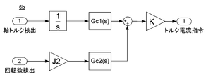
- the characteristic of the inertia compensation amount is included in the controller Gc2 in FIG. 5, and therefore if the inertia compensation amount is changed after the controller is derived once, the H ⁇ control is performed. It is necessary to derive the controller again by using the ⁇ design method.
- the characteristic of the inertia compensation amount is separated from the controller Gc2 as a gain block J2 of the shaft inertia moment as shown in FIG. Therefore, according to this embodiment, even after the controller is once introduced by the H ⁇ control or ⁇ design method, the gain J2 is adjusted without executing the H ⁇ control or ⁇ design method again.
- the inertia compensation amount can be easily changed. Further, the gain block K serving as a loop gain is also separated from the controllers Gc1 and Gc2. For this reason, similarly to the inertia compensation amount, the loop gain can be easily changed within a certain range without executing the H ⁇ control and the ⁇ design method again. Although illustration and detailed description are omitted, the same results as in FIG. 7 were obtained even in the dynamometer system using the dynamo control device 6b of the second embodiment.
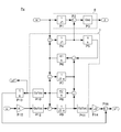
- FIG. 11 is a diagram illustrating a specific configuration of the generalized plant Pc of the third embodiment.
- the configuration different from the generalized plant Pa of Example 1 in FIG. 3 will be described.
- the same components as those in the generalized plant Pa of the first embodiment are denoted by the same reference numerals, and detailed description thereof is omitted.
- an integrator 13 two gain blocks P14 and P15, and an adder P16 are added to the generalized plant Pa of the first embodiment. More specifically, in the third embodiment, from the output of the gain block P14 of the shaft moment of inertia J2 provided at the output end of the rotation speed detection model P11, the integrator P13 provided at the output end of the torque detection model P10. An output obtained by multiplying the output obtained by subtracting the output by a predetermined proportional gain K that is a measure of control response is defined as a first observation output y1. Further, the output of the torque detection model P10 is set as a second observation output y2.
- FIG. 12 is a diagram illustrating a specific configuration of the dynamo control device 6c according to the third embodiment.
- this dynamo control device 6c two controllers Gc1 (s) and Gc2 (s) derived from the generalized plant Pc are used.
- the controller Gc1 is derived corresponding to the first observation output y1
- the controller Gc2 is derived corresponding to the second observation output y2.
- the dynamo control device 6c includes two controllers Gc1 and Gc2 derived from the generalized plant Pc, an integrator necessary for shaft inertia compensation control, and two proportional gains K and J2. Are additionally provided as shown in FIG.
- FIG. 13 is a Bode diagram of the controllers Gc1 and Gc2 of this embodiment.
- the upper part of FIG. 14 shows gain characteristics, and the lower part shows phase characteristics.
- the controller Gc1 receives a signal whose high frequency is attenuated by the integrator, and therefore the high frequency gain of the controller Gc1 increases.
- the controller Gc1 receives a signal whose high frequency is attenuated by the integrator, and therefore the high frequency gain of the controller Gc1 increases.
- FIG. 13 is a Bode diagram of the controllers Gc1 and Gc2 of this embodiment.
- the upper part of FIG. 14 shows gain characteristics, and the lower part shows phase characteristics.
- FIG. 14 is a diagram illustrating a specific configuration of the generalized plant Pd according to the fourth embodiment.
- the configuration different from the generalized plant Pa of Example 1 in FIG. 3 will be described.
- the same components as those in the generalized plant Pa of the first embodiment are denoted by the same reference numerals, and detailed description thereof is omitted.
- an integrator P13, two gain blocks P14 and P15, and two adders P16 and P17 are added from the generalized plant Pa of the first embodiment. More specifically, in the fourth embodiment, the output of the torque detection model P10 is set as an observation output y1. Further, a control response guideline is obtained by subtracting the output of the integrator P13 provided at the output terminal of the torque detection model P10 from the output of the rotation speed detection model P11 multiplied by the inertia moment J2 of the shaft. An output obtained by multiplying the predetermined proportional gain K and the control input u is used as an input to the inverter model P12.
- FIG. 15 is a diagram illustrating a specific configuration of the dynamo control device 6d according to the fourth embodiment.
- the dynamo controller 6d uses a controller Gc1 (s) derived from the generalized plant Pd corresponding to the observation output y1.
- the dynamo control device 6d includes an integrator necessary for shaft inertia compensation control and two proportional gains K and J2 in addition to the controller Gc1 derived from the generalized plant Pd. As shown in FIG.
- FIG. 16 is a Bode diagram of the controller Gc1 of this embodiment.
- the upper part of FIG. 16 shows gain characteristics, and the lower part shows phase characteristics.
- by including an integrator and a proportional gain in the generalized plant Pd effects similar to those of the second embodiment can be obtained.
- the observation output of the generalized plant Pd is only y1, only one higher-order controller Gc1 is derived. For this reason, according to the present embodiment, the bumpless process when switching from the shaft inertia compensation control to another control is facilitated.
- illustration and detailed description are omitted, the same results as in FIG. 7 were obtained even in the dynamometer system using the dynamo control device 6d of Example 4.
- FIG. 17 is a diagram illustrating a specific configuration of the generalized plant Pe of the fifth embodiment.
- the generalized plant Pc of the third embodiment in FIG. 11 Only a configuration different from the generalized plant Pc of the third embodiment in FIG. 11 will be described.
- the same components as those in the generalized plant Pc of the third embodiment are denoted by the same reference numerals, and detailed description thereof is omitted.
- the output of the torque detection model P10 was set as the observation output y1, but in the generalized plant Pe of this example, this was deleted and only one observation output was provided. That is, in the generalized plant Pe of this embodiment, from the output of the gain block P14 of the inertia moment J2 of the shaft provided at the output end of the rotational speed model P11, the integrator P13 provided at the output end of the torque detection model P10. An output obtained by multiplying the output obtained by subtracting the output by a predetermined proportional gain K, which is a measure of control response, is defined as an observation output y1.
- FIG. 18 is a diagram illustrating a specific configuration of the dynamo control device 6e according to the fifth embodiment.
- the dynamo controller 6e uses a controller Gc1 (s) derived from the generalized plant Pe in correspondence with the observation output y1.
- the dynamo control device 6e includes, in addition to the controller Gc1 derived from the generalized plant Pe, an integrator necessary for shaft inertia compensation control and two proportional gains K and J2 as shown in FIG. As shown in FIG.
- FIG. 19 is a Bode diagram of the controller Gc1 according to the fifth embodiment.
- the upper part of FIG. 19 shows gain characteristics, and the lower part shows phase characteristics.
- effects similar to those of the second embodiment can be obtained.
- the gain block K serving as the loop gain from the controller Gc1 (see FIG. 18)
- the loop gain can be easily changed within a certain range without executing the H ⁇ control or the ⁇ design method again.
- the observation output of the generalized plant Pe is only y1, only one higher-order controller Gc1 is derived.
- the bumpless process when switching from the shaft inertia compensation control to another control is facilitated.
- illustration and detailed description are omitted, the same results as in FIG. 7 were obtained even in the dynamometer system using the dynamo control device 6e of Example 5.
- FIG. 20 is a diagram illustrating a specific configuration of the generalized plant Pf of the sixth embodiment.
- the generalized plant Pc of the third embodiment in FIG. 11 will be described.
- the same components as those in the generalized plant Pc of the third embodiment are denoted by the same reference numerals, and detailed description thereof is omitted.
- a high pass filter P17 is added to the generalized plant Pc of the third embodiment. More specifically, in Example 6, the output of the high-pass filter P17 provided at the output end of the torque detection model P10 is set as the second observation output y2. The first observation output y1 is the same as that in the third embodiment.
- FIG. 21 is a diagram illustrating a specific configuration of the dynamo control device 6f according to the sixth embodiment.
- the dynamo control device 6f uses two controllers Gc1 (s) and Gc2 (s) derived from the generalized plant Pf.
- the controller Gc1 is introduced corresponding to the first observation output y1, and the controller Gc2 is derived corresponding to the second observation output y2.
- the dynamo control device 6f includes two controllers Gc1 and Gc2 derived from the generalized plant Pf, an integrator necessary for shaft inertia compensation control, and two proportional gains K, J2 and a high-pass filter are additionally provided as shown in FIG.
- FIG. 22 is a Bode diagram of the controllers Gc1 and Gc2 of this embodiment.
- the upper part of FIG. 22 shows gain characteristics, and the lower part shows phase characteristics.
- a high-pass filter is added as compared with the third embodiment.
- the low frequency characteristic of the controller Gc2 becomes a proportional characteristic, but in this example, the low frequency characteristic of the controller Gc2 becomes an integral characteristic due to the effect of the high-pass filter. .
- illustration and detailed description are omitted, the same results as in FIG. 7 were obtained even in the dynamometer system using the dynamo control device 6f of Example 3.
- FIG. 23 is a diagram illustrating a specific configuration of the generalized plant Pg according to the seventh embodiment.
- the same components as those in the generalized plant Pc of the third embodiment are denoted by the same reference numerals, and detailed description thereof is omitted.
- FIG. 24 is a diagram illustrating a specific configuration of the dynamo control device 6g according to the seventh embodiment.
- two controllers Gc1 (s) and Gc2 (s) derived from the generalized plant Pg are used.
- the controller Gc1 is derived corresponding to the first observation output y1
- the controller Gc2 is derived corresponding to the second observation output y2.
- the dynamo control device 6c includes two controllers Gc1 and Gc2 derived from the generalized plant Pg, an integrator necessary for shaft inertia compensation control, and two proportional gains K and J2. Are additionally provided as shown in FIG.
- FIG. 25 is a Bode diagram of the controllers Gc1 and Gc2 of the seventh embodiment.
- the upper part of FIG. 25 shows gain characteristics, and the lower part shows phase characteristics.
- an integrator and a proportional gain in the generalized plant Pg substantially the same effects as those of the second embodiment can be obtained.
- the gain block K serving as a loop gain from the controllers Gc1 and Gc2 (see FIG. 24)
- the loop gain can be easily changed within a certain range without executing the H ⁇ control and the ⁇ design method again.
Abstract
Description
ダイナモメータシステム100は、エンジンE及びその出力軸Sで構成される供試体Wと、この供試体Wの出力軸Sに動力吸収体として接続されたダイナモメータDと、スロットルアクチュエータ110を介してエンジンEを制御するエンジン制御器120と、インバータ130を介してダイナモメータDを制御するダイナモ制御器140と、ダイナモメータDの出力軸の回転数を検出するエンコーダ150と、供試体Wの出力軸SとダイナモメータDの出力軸との結合部の軸トルク(捩れトルク)を検出する軸トルクセンサ160と、を備える。なお図26では、クラッチ、トランスミッション、及びプロペラシャフトなどの機械要素をまとめて出力軸Sとして簡略化して示す。 FIG. 26 is a diagram illustrating a configuration of the
The
図1は、本実施形態に係るダイナモ制御装置6が用いられたダイナモメータシステム1の構成を示す図である。ダイナモメータシステム1は、供試体としてのエンジンEと、このエンジンEと略棒状のシャフトSを介して連結されたダイナモメータDと、スロットルアクチュエータ2を介してエンジンEを制御するエンジン制御装置5と、ダイナモメータDに電力を供給するインバータ3と、インバータ3を介してダイナモメータDを制御するダイナモ制御装置6と、シャフトSの捩れトルクを検出する軸トルクセンサ61と、ダイナモメータDの出力軸SDの回転数を検出するエンコーダ62と、を備える。 Hereinafter, an embodiment of the present invention will be described in detail with reference to the drawings.
FIG. 1 is a diagram illustrating a configuration of a
実施例1の一般化プラントPaにおいて、入力信号wは外部入力を示し、エンジンで発生するエンジントルクに相当する。入力信号uは図示しないコントローラから出力される制御入力を示し、インバータへ入力されるトルク電流指令に相当する。出力信号zは制御量を示し、H∞制御又はμ設計法によって小さくしたい差分値に相当する。この差分値の具体的な内容については後に詳述する。2つの出力信号y1,y2は図示しないコントローラへ入力される第1、第2観測出力を示し、それぞれ軸トルクセンサの検出値及びエンコーダの検出値に相当する。 FIG. 3 is a diagram illustrating a specific configuration of the generalized plant Pa according to the first embodiment.
In the generalized plant Pa of the first embodiment, the input signal w indicates an external input and corresponds to the engine torque generated in the engine. The input signal u indicates a control input output from a controller (not shown) and corresponds to a torque current command input to the inverter. The output signal z indicates a control amount and corresponds to a difference value that is desired to be reduced by H∞ control or μ design method. The specific contents of this difference value will be described in detail later. Two output signals y1 and y2 indicate first and second observation outputs input to a controller (not shown), and correspond to the detected value of the shaft torque sensor and the detected value of the encoder, respectively.
E…エンジン(供試体)
S…シャフト(中間結合体)
D…ダイナモメータ
Pa,Pb,Pc,Pd,Pe,Pf,Pg…一般化プラント
3…インバータ
6a,6b,6c,6d,6e,6f,6g…ダイナモ制御装置
61…軸トルクセンサ(トルク検出器)
62…エンコーダ(回転数検出器)
7…動特性モデル
8…制御量演算部
P4~P9…機械モデル
P10…トルク検出モデル
P11…回転数検出モデル
P12…インバータモデル 1 ... Dynamometer system E ... Engine (specimen)
S ... Shaft (intermediate coupling)
D ... Dynamometer Pa, Pb, Pc, Pd, Pe, Pf, Pg ...
62 ... Encoder (rotation speed detector)
7 ... Dynamic
Claims (8)
- 動力を発生する供試体と中間結合体を介して連結されたダイナモメータと、前記中間結合体の捩れトルクを検出するトルク検出器と、前記ダイナモメータの回転数を検出する回転数検出器と、前記ダイナモメータに電力を供給するインバータと、を備えたダイナモメータシステムにおいて、前記トルク検出器及び前記回転数検出器の検出信号に基づいて前記インバータへのトルク電流指令を生成するダイナモメータシステムのダイナモ制御装置であって、
前記ダイナモ制御装置は、前記供試体で発生するトルクに相当する外部入力及び前記トルク電流指令に相当する制御入力から所定の観測出力及び制御量を出力する一般化プラントに対し、前記外部入力から前記制御量までの応答を小さくするようにH∞制御又はμ設計法と呼称される制御系設計方法によって設計されたコントローラを含み、
前記一般化プラントは、前記外部入力及び前記制御入力から前記供試体の角加速度を出力するように前記ダイナモメータシステムの特性を同定した動特性モデルを含み、
前記一般化プラントの制御量は、前記外部入力に基づいて算出した前記供試体単体の角加速度と、前記動特性モデルによって算出した前記供試体の角加速度との差分に、積分特性を有する重み関数を乗じた信号であることを特徴とするダイナモメータシステムのダイナモ制御装置。 A dynamometer connected via a specimen to generate power and an intermediate coupling, a torque detector for detecting torsional torque of the intermediate coupling, and a rotational speed detector for detecting the rotational speed of the dynamometer; In a dynamometer system comprising an inverter for supplying power to the dynamometer, a dynamometer for a dynamometer system that generates a torque current command to the inverter based on detection signals of the torque detector and the rotation speed detector A control device,
The dynamo control device, from the external input to the generalized plant that outputs a predetermined observation output and control amount from the external input corresponding to the torque generated in the specimen and the control input corresponding to the torque current command Including a controller designed by a control system design method called H∞ control or μ design method so as to reduce the response to the controlled variable,
The generalized plant includes a dynamic characteristic model that identifies characteristics of the dynamometer system so as to output angular acceleration of the specimen from the external input and the control input,
The control amount of the generalized plant is a weight function having an integral characteristic in the difference between the angular acceleration of the single specimen calculated based on the external input and the angular acceleration of the specimen calculated by the dynamic characteristic model. A dynamo control device for a dynamometer system, characterized in that - 前記一般化プラントの動特性モデルは、前記インバータの特性を同定したインバータモデルと、前記供試体と前記中間結合体と前記ダイナモメータとを連結して構成される3慣性系の特性を同定した機械モデルと、前記トルク検出器の特性を同定したトルク検出モデルと、前記回転数検出器の特性を同定した回転数検出モデルと、を備えることを特徴とする請求項1に記載のダイナモメータシステムのダイナモ制御装置。 The dynamic characteristic model of the generalized plant includes an inverter model that identifies the characteristics of the inverter, and a machine that identifies the characteristics of a three-inertia system configured by connecting the specimen, the intermediate combination, and the dynamometer. The dynamometer system according to claim 1, comprising a model, a torque detection model that identifies the characteristics of the torque detector, and a rotation speed detection model that identifies the characteristics of the rotation speed detector. Dynamo control device.
- 前記制御入力に所定の比例ゲインを乗算して得られる出力を前記インバータモデルへの入力とし、
前記トルク検出モデルの出力端に設けられた積分器の出力を第1観測出力とし、
前記回転数検出モデルの出力端に設けられた比例ゲインの出力を第2観測出力とすることを特徴とする請求項2に記載のダイナモメータシステムのダイナモ制御装置。 An output obtained by multiplying the control input by a predetermined proportional gain is an input to the inverter model,
The output of the integrator provided at the output terminal of the torque detection model is the first observation output,
The dynamometer control device for a dynamometer system according to claim 2, wherein an output of a proportional gain provided at an output end of the rotation speed detection model is used as a second observation output. - 前記制御入力を前記インバータモデルへの入力とし、
所定の比例ゲインが乗算された前記回転数検出モデルの出力と前記トルク検出モデルの出力端に設けられた積分器の出力との差分に所定の比例ゲインを乗算して得られる出力を第1観測出力とし、
前記トルク検出モデルの出力を第2観測出力とすることを特徴とする請求項2に記載のダイナモメータシステムのダイナモ制御装置。 The control input is an input to the inverter model,
First observation is an output obtained by multiplying a difference between an output of the rotation speed detection model multiplied by a predetermined proportional gain and an output of an integrator provided at an output end of the torque detection model by a predetermined proportional gain. As output,
The dynamometer control device for a dynamometer system according to claim 2, wherein the output of the torque detection model is a second observation output. - 所定の比例ゲインが乗算された前記回転数検出モデルの出力と前記トルク検出モデルの出力端に設けられた積分器の出力との差分に所定の比例ゲインを乗じて得られる出力と、前記制御入力とを合成して得られる出力を前記インバータモデルへの入力とし、
前記トルク検出モデルの出力を観測出力とすることを特徴とする請求項2に記載のダイナモメータシステムのダイナモ制御装置。 An output obtained by multiplying a difference between an output of the rotation speed detection model multiplied by a predetermined proportional gain and an output of an integrator provided at an output end of the torque detection model by a predetermined proportional gain; and the control input As an input to the inverter model, the output obtained by combining
The dynamometer control device for a dynamometer system according to claim 2, wherein the output of the torque detection model is used as an observation output. - 前記制御入力を前記インバータモデルへの入力とし、
所定の比例ゲインが乗算された前記回転数検出モデルの出力と前記トルク検出モデルの出力端に設けられた積分器の出力との差分に所定の比例ゲインを乗じて得られる出力を観測出力とすることを特徴とする請求項2に記載のダイナモメータシステムのダイナモ制御装置。 The control input is an input to the inverter model,
An output obtained by multiplying the difference between the output of the rotation speed detection model multiplied by a predetermined proportional gain and the output of the integrator provided at the output end of the torque detection model by the predetermined proportional gain is used as an observation output. The dynamometer control device for a dynamometer system according to claim 2. - 前記制御入力を前記インバータモデルへの入力とし、
所定の比例ゲインが乗算された前記回転数検出モデルの出力と前記トルク検出モデルの出力端に設けられた積分器の出力との差分に所定の比例ゲインを乗算して得られる出力を第1観測出力とし、
前記トルク検出モデルの出力端に設けられたハイパスフィルタの出力を第2観測出力とすることを特徴とする請求項2に記載のダイナモメータシステムのダイナモ制御装置。 The control input is an input to the inverter model,
First observation is an output obtained by multiplying a difference between an output of the rotation speed detection model multiplied by a predetermined proportional gain and an output of an integrator provided at an output end of the torque detection model by a predetermined proportional gain. As output,
The dynamometer control device for a dynamometer system according to claim 2, wherein an output of a high-pass filter provided at an output end of the torque detection model is used as a second observation output. - 前記制御入力に所定の比例ゲインを乗算して得られる出力を前記インバータモデルへの入力とし、
前記トルク検出モデルの出力を第1観測出力とし、
所定の比例ゲインが乗算された前記回転数検出モデルの出力と前記トルク検出モデルの出力との差分を第2観測出力とすることを特徴とする請求項2に記載のダイナモメータシステムのダイナモ制御装置。 An output obtained by multiplying the control input by a predetermined proportional gain is an input to the inverter model,
The output of the torque detection model is the first observation output,
The dynamometer control device for a dynamometer system according to claim 2, wherein a difference between an output of the rotation speed detection model multiplied by a predetermined proportional gain and an output of the torque detection model is used as a second observation output. .
Priority Applications (2)
| Application Number | Priority Date | Filing Date | Title |
|---|---|---|---|
| KR1020167011590A KR101659363B1 (en) | 2013-10-07 | 2014-10-06 | Dynamometer system |
| US15/027,932 US9739687B2 (en) | 2013-10-07 | 2014-10-06 | Dynamometer system |
Applications Claiming Priority (2)
| Application Number | Priority Date | Filing Date | Title |
|---|---|---|---|
| JP2013210518A JP5800001B2 (en) | 2013-10-07 | 2013-10-07 | Dynamometer system |
| JP2013-210518 | 2013-10-07 |
Publications (1)
| Publication Number | Publication Date |
|---|---|
| WO2015053220A1 true WO2015053220A1 (en) | 2015-04-16 |
Family
ID=52813036
Family Applications (1)
| Application Number | Title | Priority Date | Filing Date |
|---|---|---|---|
| PCT/JP2014/076691 WO2015053220A1 (en) | 2013-10-07 | 2014-10-06 | Dynamometer system |
Country Status (4)
| Country | Link |
|---|---|
| US (1) | US9739687B2 (en) |
| JP (1) | JP5800001B2 (en) |
| KR (1) | KR101659363B1 (en) |
| WO (1) | WO2015053220A1 (en) |
Families Citing this family (15)
| Publication number | Priority date | Publication date | Assignee | Title |
|---|---|---|---|---|
| SE538492C2 (en) * | 2014-03-31 | 2016-08-02 | Rototest Int Ab | Procedure and system for use in dynamometer testing of a motor vehicle |
| JP6044649B2 (en) * | 2015-01-19 | 2016-12-14 | 株式会社明電舎 | Control device for dynamometer system |
| JP6168126B2 (en) | 2015-11-09 | 2017-07-26 | 株式会社明電舎 | Dynamo control device of dynamometer system and engine start method thereof |
| JP6149948B1 (en) * | 2016-01-07 | 2017-06-21 | 株式会社明電舎 | Specimen characteristic estimation method and specimen characteristic estimation apparatus |
| JP6217797B1 (en) * | 2016-06-22 | 2017-10-25 | 株式会社明電舎 | Resonance suppression control circuit, test system using the same, and resonance suppression control circuit design method |
| JP6659491B2 (en) | 2016-07-27 | 2020-03-04 | 株式会社エー・アンド・デイ | Engine test equipment |
| JP6659492B2 (en) | 2016-07-27 | 2020-03-04 | 株式会社エー・アンド・デイ | Engine test equipment |
| JP6493578B1 (en) * | 2018-02-08 | 2019-04-03 | 株式会社明電舎 | Mechanical property estimation method and mechanical property estimation apparatus for test system |
| JP6645525B2 (en) * | 2018-02-23 | 2020-02-14 | 株式会社明電舎 | Test system controller |
| KR102256390B1 (en) * | 2018-09-07 | 2021-05-26 | 메이덴샤 코포레이션 | Dynamometer control device |
| JP6660038B1 (en) * | 2018-11-05 | 2020-03-04 | 株式会社明電舎 | Shaft torque control device |
| CN109839823B (en) * | 2019-01-15 | 2020-06-26 | 中国科学院西安光学精密机械研究所 | Asynchronous hysteresis compensation-linear quadratic form H of piezoelectric deformable mirror∞Control method and system |
| JP6737363B1 (en) * | 2019-02-28 | 2020-08-05 | 株式会社明電舎 | Dynamometer controller |
| KR20230152245A (en) | 2022-04-27 | 2023-11-03 | 동의대학교 산학협력단 | Miniaturized mobile dynamo system |
| JP7380762B1 (en) * | 2022-06-27 | 2023-11-15 | 株式会社明電舎 | test system |
Citations (4)
| Publication number | Priority date | Publication date | Assignee | Title |
|---|---|---|---|---|
| JP2003121308A (en) * | 2001-10-11 | 2003-04-23 | Meidensha Corp | Engine bench system and method for measuring characteristics of engine |
| JP2003149085A (en) * | 2001-11-08 | 2003-05-21 | Meidensha Corp | Engine bench system and engine characteristics measuring method |
| JP2008286614A (en) * | 2007-05-17 | 2008-11-27 | Meidensha Corp | Electric inertial control method |
| JP2012068200A (en) * | 2010-09-27 | 2012-04-05 | Meidensha Corp | Shaft torque control device of dynamometer |
Family Cites Families (11)
| Publication number | Priority date | Publication date | Assignee | Title |
|---|---|---|---|---|
| JPH01173848A (en) * | 1987-12-28 | 1989-07-10 | Toyota Motor Corp | Travel resistance setting device |
| JP4766039B2 (en) * | 2007-11-30 | 2011-09-07 | 株式会社明電舎 | Control method of engine bench system |
| AT10301U3 (en) * | 2008-09-01 | 2009-09-15 | Avl List Gmbh | METHOD AND REGULATION FOR REGULATING A REGULAR TRACK WITH A RECYCLING WORKING CYCLE |
| JP5758659B2 (en) * | 2011-03-17 | 2015-08-05 | トヨタ自動車株式会社 | Engine test apparatus and engine test method |
| KR101548293B1 (en) * | 2012-01-13 | 2015-08-28 | 메이덴샤 코포레이션 | Drive-train testing system |
| JP5605383B2 (en) * | 2012-02-29 | 2014-10-15 | 株式会社明電舎 | Dynamometer system |
| JP5304913B2 (en) * | 2012-03-02 | 2013-10-02 | 株式会社明電舎 | Dynamometer system |
| JP5344067B1 (en) * | 2012-06-13 | 2013-11-20 | 株式会社明電舎 | Dynamometer system |
| US9234820B2 (en) * | 2012-07-09 | 2016-01-12 | Meidensha Corporation | Testing system for drivetrain |
| JP5708704B2 (en) * | 2013-05-15 | 2015-04-30 | 株式会社明電舎 | Engine bench system |
| JP5776731B2 (en) * | 2013-06-19 | 2015-09-09 | 株式会社明電舎 | Drivetrain testing system |
-
2013
- 2013-10-07 JP JP2013210518A patent/JP5800001B2/en active Active
-
2014
- 2014-10-06 WO PCT/JP2014/076691 patent/WO2015053220A1/en active Application Filing
- 2014-10-06 KR KR1020167011590A patent/KR101659363B1/en active IP Right Grant
- 2014-10-06 US US15/027,932 patent/US9739687B2/en active Active
Patent Citations (4)
| Publication number | Priority date | Publication date | Assignee | Title |
|---|---|---|---|---|
| JP2003121308A (en) * | 2001-10-11 | 2003-04-23 | Meidensha Corp | Engine bench system and method for measuring characteristics of engine |
| JP2003149085A (en) * | 2001-11-08 | 2003-05-21 | Meidensha Corp | Engine bench system and engine characteristics measuring method |
| JP2008286614A (en) * | 2007-05-17 | 2008-11-27 | Meidensha Corp | Electric inertial control method |
| JP2012068200A (en) * | 2010-09-27 | 2012-04-05 | Meidensha Corp | Shaft torque control device of dynamometer |
Also Published As
| Publication number | Publication date |
|---|---|
| US9739687B2 (en) | 2017-08-22 |
| KR101659363B1 (en) | 2016-09-26 |
| JP2015075361A (en) | 2015-04-20 |
| US20160252428A1 (en) | 2016-09-01 |
| KR20160055961A (en) | 2016-05-18 |
| JP5800001B2 (en) | 2015-10-28 |
Similar Documents
| Publication | Publication Date | Title |
|---|---|---|
| JP5800001B2 (en) | Dynamometer system | |
| JP6044649B2 (en) | Control device for dynamometer system | |
| JP6545560B2 (en) | Active vibration reduction controller for hybrid vehicle and method thereof | |
| JP4766039B2 (en) | Control method of engine bench system | |
| US9242375B2 (en) | Control device for power device | |
| JP4784451B2 (en) | Control method and apparatus for engine bench system | |
| CN104993766B (en) | A kind of two quality system resonance suppressing methods | |
| JP5136247B2 (en) | Dynamometer control method for engine bench system | |
| JP5605127B2 (en) | Shaft torque control device | |
| JP2010136616A5 (en) | ||
| US9796087B2 (en) | Control system for power unit | |
| JP6481792B2 (en) | Power system test equipment | |
| JP6659492B2 (en) | Engine test equipment | |
| CN111512134A (en) | Method for estimating internal effective torque of torque generator | |
| JP5989694B2 (en) | Control device, control method, and control program | |
| WO2017188271A1 (en) | Device for controlling dynamometer of test system | |
| JP2008233075A (en) | Vibration-testing apparatus | |
| JP6497408B2 (en) | Electric inertia control device | |
| JP6007831B2 (en) | Power system test equipment | |
| JP5605128B2 (en) | Dynamometer shaft torque control device | |
| JP2011160574A (en) | Speed control device for motor | |
| JP5895405B2 (en) | Control device for engine bench system | |
| JP2014142317A (en) | Testing device for power system | |
| JP4019709B2 (en) | Engine bench system | |
| JP7426319B2 (en) | Control device |
Legal Events
| Date | Code | Title | Description |
|---|---|---|---|
| 121 | Ep: the epo has been informed by wipo that ep was designated in this application |
Ref document number: 14853036 Country of ref document: EP Kind code of ref document: A1 |
|
| NENP | Non-entry into the national phase |
Ref country code: DE |
|
| WWE | Wipo information: entry into national phase |
Ref document number: 15027932 Country of ref document: US |
|
| ENP | Entry into the national phase |
Ref document number: 20167011590 Country of ref document: KR Kind code of ref document: A |
|
| 122 | Ep: pct application non-entry in european phase |
Ref document number: 14853036 Country of ref document: EP Kind code of ref document: A1 |