JP5605127B2 - Shaft torque control device - Google Patents
Shaft torque control device Download PDFInfo
- Publication number
- JP5605127B2 JP5605127B2 JP2010215210A JP2010215210A JP5605127B2 JP 5605127 B2 JP5605127 B2 JP 5605127B2 JP 2010215210 A JP2010215210 A JP 2010215210A JP 2010215210 A JP2010215210 A JP 2010215210A JP 5605127 B2 JP5605127 B2 JP 5605127B2
- Authority
- JP
- Japan
- Prior art keywords
- shaft torque
- dynamometer
- drive motor
- torque
- command value
- Prior art date
- Legal status (The legal status is an assumption and is not a legal conclusion. Google has not performed a legal analysis and makes no representation as to the accuracy of the status listed.)
- Active
Links
Images


Description
本発明は、2慣性系または2慣性系に近似可能な動力システムまたはエンジンベンチシステムの軸トルク制御装置に係り、特にエンジンベンチシステムにおけるエンジンの回転数制御に対する動力計の軸トルク制御に関するものである。 The present invention relates to a two-inertia system or a power system that can approximate a two-inertia system or a shaft torque control device of an engine bench system, and more particularly to a shaft torque control of a dynamometer for engine speed control in the engine bench system. .
産業用ロボットや動力試験システムなど、モータと負荷を軸結合する動力伝達系では、結合軸の捩り振動の抑制と外乱抑圧が課題として挙げられており、この課題を解決する手法として動力伝達システムのモデルを2慣性系として表現し、このモデルを基にモータの軸トルク制御で振動抑制などを図る手法が提案されている。 In power transmission systems that link motors and loads, such as industrial robots and power test systems, suppression of torsional vibrations and disturbance suppression of the combined shafts have been raised as challenges. A method has been proposed in which a model is expressed as a two-inertia system, and vibration suppression is performed by controlling the motor shaft torque based on this model.
図10は一般的なエンジンベンチシステム(エンジンの動力試験システム)の機械系と制御系の構成を示す。機械系は、供試対象となるエンジン1にクラッチ2と変速機(MT)3およびプロペラシャフト4を結合し、このプロペラシャフト4に軸トルクメータ5を介して動力計6を結合する。動力計6の回転軸にはインクリメンタルエンコーダにした回転数検出器7を結合する。制御系は、エンジン1を制御するエンジン制御器8とスロットルアクチェータ9を設け、動力計6を制御する動力計制御器10とインバータ(電力変換器)11を設ける。
FIG. 10 shows the configuration of a mechanical system and a control system of a general engine bench system (engine power test system). In the mechanical system, a
動力計制御器10にはエンコーダ7で検出する回転数や軸トルクメータ5で検出する軸トルクがフィードバックされ、動力計の軸トルクや回転数が制御される。エンジン1もエンジン制御器8により出力などが制御される。
The
図10には記載されていないが、エンジン1にはエンジン回転数をアイドル回転数に制御するエンジンコントロールユニット(ECU)も設置されている。動力計制御器10は、軸トルクメータで検出したトルクが「軸トルク指令」と一致するように、インバータ11へのトルク指令を算出する。
Although not shown in FIG. 10, the
図11は、図10に示したエンジンベンチシステムにおいて、エンジン1がアイドル回転数制御され、動力計6を軸トルク制御する場合の機械モデルと制御系構成図を示す。一般的なエンジンベンチシステムでは、プロペラシャフト4の慣性モーメントが動力計6やエンジン1の慣性モーメントと比較して小さく、また、プロペラシャフト4などのねじれ剛性はクラッチ2の捩れ剛性よりも非常に大きいため、図11のように2慣性系モデル(2個の慣性モーメントとそれらを結合する弾性要素からなるモデル)とみなすことができる。
FIG. 11 shows a machine model and a control system configuration diagram in the case where the
図11に示す制御系はエンジンのアイドル回転数制御と動力計の軸トルク制御を行う場合である。エンジンのアイドル回転数制御は、速度制御器8Aが何らかの手段により検出したエンジン回転数があらかじめ指定されたアイドル回転数指令値に一致するように、エンジンの回転数を制御する。軸トルク制御は、軸トルク制御器10Aが軸トルクメータ5により検出される軸トルク(クラッチの捩れトルクにほぼ等しい)をあらかじめ指定した軸トルク指令値に一致するように、動力計6のトルクを制御する。
The control system shown in FIG. 11 is a case where engine idle speed control and dynamometer shaft torque control are performed. In the engine idle speed control, the engine speed is controlled so that the engine speed detected by the
例えば、特許文献1では、2慣性系とみなすことのできる図11の機械系構成のエンジンベンチシステムにおいて、動力計6で軸トルク制御をする場合の、動力計トルク制御方法とその装置を提案している。
For example,
特許文献1では、図11に示す2慣性系機械モデルの情報(エンジン慣性Je、動力計慣性Jm、クラッチばね剛性K12、エンジン角速度ω1、動力計角速度ω2)を用いて、軸トルク指令T12rと軸トルク検出値T12との偏差でPID制御する軸トルク制御器とする。このときの動力計トルク制御信号T2の演算は、以下の積分要素と比例・微分要素をもつPID制御方式とする。
In
T2=(Ki/s)*(T12r−T12)−(Kp+s*Kd)/(a2*s*s+a1*s+1)*T12
ただし、Ki:積分係数、T12r:軸トルク指令値、T12:軸トルク検出値、Kp:比例係数、Kd:微分係数、a1、a2:比例・微分要素のフィルタ係数
さらに、特許文献1では、エンジンと動力計の結合シャフトが非線形バネ特性をもつ場合、共振周波数が軸トルクの大きさによって変化するのを補償できるよう、軸トルク制御器のPID制御の積分、比例、微分の各要素の係数(積分係数Ki、比例係数Kp、微分係数Kd、フィルタ係数a1,a2)を軸トルク検出値T12を基に自動調整できるようにしている。
T2 = (Ki / s) * (T12r−T12) − (Kp + s * Kd) / (a2 * s * s + a1 * s + 1) * T12
However, Ki: integral coefficient, T12r: shaft torque command value, T12: shaft torque detected value, Kp: proportional coefficient, Kd: differential coefficient, a1, a2: filter coefficient of proportional / differential element If the shaft of the dynamometer has a nonlinear spring characteristic, the coefficients of the integral, proportional, and differential elements of the PID control of the shaft torque controller (to compensate for changes in the resonance frequency depending on the magnitude of the shaft torque ( The integral coefficient Ki, the proportional coefficient Kp, the differential coefficient Kd, and the filter coefficients a1 and a2) can be automatically adjusted based on the detected shaft torque value T12.
特許文献1では、図10の軸トルク制御器10Aの構成方法を提案するものであるが、その制御方法の適用時にエンジンがアイドル回転数制御されていることを想定していない。
一般に、エンジン始動時にはエンジンがアイドル回転数になるようにエンジン制御器(ECU)8Aにより制御されている。そこで、エンジン制御器(ECU)8Aによりアイドル回転数制御されているエンジンに特許文献1の軸トルク制御手法を適用した場合、アイドル回転数制御と軸トルク制御が干渉し、軸トルクが振動することがある。
Generally, when the engine is started, the engine is controlled by an engine controller (ECU) 8A so that the engine has an idling speed. Therefore, when the shaft torque control method of
図12は、上記の軸トルク制御がされている状態において、エンジンを始動した場合のシミュレーション波形である。ただし、軸トルク指令値は0[Nm]、エンジン回転数指令値は500[rpm]としている。 FIG. 12 is a simulation waveform when the engine is started in the state where the above-described shaft torque control is performed. However, the shaft torque command value is 0 [Nm] and the engine speed command value is 500 [rpm].
図12では、軸トルク、及び、エンジン回転数が約1[Hz]で大きく振動している。実車に搭載されているエンジンでは、通常、このような振動は発生せず、この振動現象は、特許文献1の軸トルク制御方式をエンジンベンチシステムの動力計制御へ適用した場合に発生する。このような振動が発生すると、エンジンの燃費、排ガスが実車でのそれらと大きく異なるようになり、エンジンベンチシステムでのエンジンの試験を適切に実施することが困難となる。
In FIG. 12, the shaft torque and the engine speed vibrate greatly at about 1 [Hz]. In an engine mounted on an actual vehicle, such vibration does not normally occur, and this vibration phenomenon occurs when the shaft torque control method of
次に、特許文献1では、前記のように、エンジンからガタをもつクラッチを介して動力計に軸結合するエンジンベンチシステムに適用可能としている。図13はガタの大きなクラッチの特性例である。
Next, in
図14、図15、図16は、図13の特性を持つクラッチを使用したエンジンベンチシステムに特許文献1の手法を適用した場合のシミュレーション波形を示す。各図は、図13のばね剛性が柔らかい部分(ガタ部)の剛性、硬い部分の剛性、両者の中間的な剛性に合わせて特許文献1の手法でPID制御のゲイン調整を行った場合のシミュレーション結果である。いずれの場合においても、軸トルクやエンジン回転数が振動し、エンジン試験を適切に実施することができない。
14, FIG. 15 and FIG. 16 show simulation waveforms when the method of
本発明の目的は、2慣性系または2慣性系に近似可能な動力システムまたはエンジンベンチシステムにおいて、負荷側モータ(エンジン)の回転数制御と駆動モータ(動力計)の軸トルク制御の干渉を抑制した軸トルク制御ができ、特にエンジンからガタをもつクラッチを介して動力計に軸結合したシステムの軸トルクやエンジン回転数の振動も抑制できる軸トルク制御装置を提供することにある。 The object of the present invention is to suppress interference between the rotational speed control of the load-side motor (engine) and the shaft torque control of the drive motor (dynamometer) in a two-inertia system or a power system or engine bench system that can approximate a two-inertia system. It is an object of the present invention to provide a shaft torque control apparatus that can control shaft torque of a system that is coupled to a dynamometer through a clutch having a backlash from the engine and vibrations of the engine speed.
本発明は、前記の課題を解決するため、負荷側モータ(エンジン)が速度制御されている場合に駆動モータ(動力計)に対するトルク外乱を外乱オブザーバにより推定して駆動モータのトルク指令値にフィードバックすることにより駆動モータの加速度制御系を構成し、さらに、軸トルク検出値または軸トルク推定値を共振比制御理論に基づいて決定されるゲインで駆動モータの加速度指令値にフィードバックし、さらにまた、駆動モータの速度検出値を所定の共振抑制効果が得られるように決定したゲインで駆動モータの加速度指令値にフィ−ドバックし、及び、軸トルク指令値に軸トルク検出値が追従するように比例積分制御系を構成するものであり、以下の構成を特徴とする。 In order to solve the above problems, the present invention estimates a torque disturbance to the drive motor (dynamometer) by a disturbance observer when the speed of the load side motor (engine) is controlled, and feeds it back to the torque command value of the drive motor. By configuring the acceleration control system of the drive motor, the shaft torque detection value or the shaft torque estimation value is fed back to the drive motor acceleration command value with a gain determined based on the resonance ratio control theory. The drive motor speed detection value is fed back to the drive motor acceleration command value with a gain determined so as to obtain a predetermined resonance suppression effect, and the shaft torque command value is proportional to the shaft torque command value. The integral control system is configured and has the following configuration.
(1)負荷側モータと駆動モータを軸結合した機械系と、前記負荷側モータの回転数制御と前記駆動モータの軸トルク制御を行う制御系とを備えた2慣性系または2慣性系に近似可能な動力システムの軸トルク制御装置であって、
前記駆動モータに対するトルク外乱を外乱オブザーバにより推定して該駆動モータのトルク指令値にフィードバックする駆動モータの加速度制御系と、
前記駆動モータの軸トルク指令値と軸トルク検出値との偏差を比例積分演算して該駆動モータの加速度指令値を得る比例積分制御系と、
前記駆動モータの軸トルク検出値を共振比制御理論に基づいて決定したゲインで該駆動モータの加速度指令値にフィードバックする手段と、
前記駆動モータの速度検出値を所定のゲインで該駆動モータの加速度指令値にフィ−ドバックする手段と、
を備えたことを特徴とする。
(1) A two-inertia system or a two-inertia system provided with a mechanical system in which a load-side motor and a drive motor are axially coupled, and a control system that performs rotational speed control of the load-side motor and shaft torque control of the drive motor A shaft torque control device for a possible power system,
An acceleration control system of the drive motor that estimates a torque disturbance to the drive motor by a disturbance observer and feeds back to the torque command value of the drive motor;
A proportional-integral control system that obtains an acceleration command value of the drive motor by performing a proportional-integral calculation of a deviation between the shaft torque command value of the drive motor and a detected shaft torque value;
Means for feeding back the shaft torque detection value of the drive motor to the acceleration command value of the drive motor with a gain determined based on a resonance ratio control theory;
Means for feeding back the speed detection value of the drive motor to the acceleration command value of the drive motor with a predetermined gain;
It is provided with.
(2)前記駆動モータが軸トルク検出器をもたない場合、該駆動モータの回転数とトルク指令値とから軸トルクオブザーバで推定して前記軸トルク検出値とすることを特徴とする。 (2) When the drive motor does not have a shaft torque detector, the shaft torque detected value is estimated by a shaft torque observer from the rotational speed of the drive motor and a torque command value.
(3)エンジンと動力計を軸結合した機械系と、前記エンジンの回転数制御と前記動力計の軸トルク制御を行う制御系とを備えた2慣性系または2慣性系に近似可能なエンジンベンチシステムの軸トルク制御装置であって、
前記動力計に対するトルク外乱を外乱オブザーバにより推定して該動力計のトルク指令値にフィードバックする駆動モータの加速度制御系と、
前記動力計の軸トルク指令値と軸トルク検出値との偏差を比例積分演算して該動力計の加速度指令値を得る比例積分制御系と、
前記動力計の軸トルク検出値を共振比制御理論に基づいて決定したゲインで該動力計の加速度指令値にフィードバックする手段と、
前記動力計の速度検出値を所定のゲインで該動力計の加速度指令値にフィ−ドバックする手段と、
を備えたことを特徴とする。
(3) A two-inertia system or an engine bench that can be approximated to a two-inertia system, comprising a mechanical system in which an engine and a dynamometer are axially coupled, and a control system that controls the rotational speed of the engine and the shaft torque of the dynamometer A shaft torque control device for a system,
An acceleration control system of a drive motor that estimates a torque disturbance for the dynamometer by a disturbance observer and feeds back to the torque command value of the dynamometer;
A proportional-integral control system that obtains an acceleration command value of the dynamometer by performing a proportional-integral calculation of a deviation between the shaft torque command value of the dynamometer and the detected shaft torque value;
Means for feeding back the shaft torque detection value of the dynamometer to an acceleration command value of the dynamometer with a gain determined based on a resonance ratio control theory;
Means for feeding back the speed detection value of the dynamometer to an acceleration command value of the dynamometer with a predetermined gain;
It is provided with.
(4)前記動力計が軸トルク検出器をもたない場合、該動力計の回転数とトルク指令値とから軸トルクオブザーバで推定して前記軸トルク検出値とすることを特徴とする。 (4) When the dynamometer does not have a shaft torque detector, the shaft torque detected value is estimated by a shaft torque observer from the rotational speed of the dynamometer and a torque command value.
以上のとおり、本発明によれば、負荷側モータ(エンジン)が速度制御されている場合に駆動モータ(動力計)に対するトルク外乱を外乱オブザーバにより推定して駆動モータのトルク指令値にフィードバックすることにより駆動モータの加速度制御系を構成し、さらに、軸トルク検出値または軸トルク推定値を共振比制御理論に基づいて決定されるゲインで駆動モータの加速度指令値にフィードバックし、さらにまた、駆動モータの速度検出値を所定の共振抑制効果が得られるように決定したゲインで駆動モータの加速度指令値にフィ−ドバックし、及び、軸トルク指令値に軸トルク検出値が追従するように比例積分制御系を構成するため、負荷側モータ(エンジン)の回転数制御と駆動モータ(動力計)の軸トルク制御の干渉を抑制した軸トルク制御ができ、特にエンジンからガタをもつクラッチを介して動力計に軸結合したシステムの軸トルクやエンジン回転数の振動も抑制できる。 As described above, according to the present invention, when the speed of the load motor (engine) is controlled, the torque disturbance to the drive motor (dynamometer) is estimated by the disturbance observer and fed back to the torque command value of the drive motor. To constitute an acceleration control system for the drive motor, and further feed back the detected shaft torque value or estimated shaft torque value to the drive motor acceleration command value with a gain determined based on the resonance ratio control theory. The speed detection value is fed back to the drive motor acceleration command value with a gain determined so as to obtain a predetermined resonance suppression effect, and the proportional integral control is performed so that the shaft torque detection value follows the shaft torque command value. Since the system is configured, interference between the rotational speed control of the load side motor (engine) and the shaft torque control of the drive motor (dynamometer) is suppressed. Can torque control, in particular also suppressed the shaft coupling with vibration of the shaft torque and the engine speed of the system dynamometer through a clutch with a backlash from the engine.
実施形態(1)
図1は動力計の軸トルク制御装置の構成を示し、エンジンベンチシステムに適用した場合である。50は、図11に示すエンジンベンチシステムの2慣性系機械モデルであり、エンジンのアイドル回転数制御要素50Aと、クラッチの非線形特性要素50Bを含めた機械モデルとし、エンジンが回転数制御され、エンジンからガタをもつクラッチを介して動力計に軸結合したシステムの軸トルク制御を可能とする。
Embodiment (1)
FIG. 1 shows a configuration of a shaft torque control device for a dynamometer, which is applied to an engine bench system.
このモデルにおけるエンジン1、クラッチ2および動力計6における定数等は、図11中に示すように、以下のものとする。なお、sはラプラス演算子である。
The constants and the like in the
Je=エンジン慣性モーメント、Jm=動力計慣性モーメント、K12=クラッチばね剛性、TI=エンジントルク、T2=動力計トルク、ω1=エンジン角速度、ω2=動力計角速度
図1に示す軸トルク制御器10Aは、軸トルク指令(T12r)と軸トルク検出値(T12)と動力計回転数検出値(ω2)を基に動力計トルク指令を求める。ここで、軸トルク制御器10Aは、図2に示すブロック構成とする。図2において、外乱オブザーバ21は、動力計の慣性モーメントJmに回転数ω2を疑似微分した加速度(dω2/dt)を乗じてトルクJm(dω2/dt)を求め、このトルクJm(dω2/dt)と動力計トルク指令Trefから動力計の外乱トルク(エンジンのアイドル回転により動力計に発生するトルク)を推定し、そのトルクTdismを動力計トルク指令にフィードバックすることにより動力計の加速度制御系を構成し、軸トルク振動を抑制した軸トルク制御を得る。
Je = engine moment of inertia, Jm = dynamometer moment of inertia, K12 = clutch spring stiffness, TI = engine torque, T2 = dynamometer torque, ω1 = engine angular velocity, ω2 = dynamometer angular velocity A
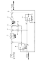
図3は外乱オブザーバ21の回路構成図を示す。同図中、「gdis」は外乱オブザーバの応答速度を決める定数(単位:1/秒)であり、乗算器21Aは動力計回転数ω2に「gdis」を乗じて加速度を求め、これに動力計慣性モーメントJmを乗じてトルクに変換する。加算器21Bは動力計トルク指令Trefと乗算器21Aの出力トルクの加算値を求める。低域通過フィルタ(LPF)21Cは加算器21Bの出力について、定数「gdis」をもつ伝達関数を有して直流成分を抽出する。減算器21Dは低域通過フィルタ(LPF)21Cの出力から乗算器21Aの出力を減じて外乱トルク推定値Tdismを得る。
FIG. 3 shows a circuit configuration diagram of the
次に、図2において、軸トルク制御器10Aの軸トルク検出器22は、軸トルクメータのトルク検出信号を軸トルク検出値に換算し、比例積分(PI)制御器23は軸トルク検出値と軸トルク指令との偏差を比例積分(PI)演算して動力計の加速度指令を求める。乗算器24は、加速度指令に動力計の慣性モーメントJmを乗じることで動力計トルク指令を求める。加算器25は、乗算器24からの動力計トルク指令に外乱オブザーバ21で求めた外乱トルク推定値を加算することで、エンジンのアイドル回転数制御と動力計の軸トルク制御の干渉を抑制するための動力計トルク指令を得る。
Next, in FIG. 2, the
係数器26、28と減算器27、29は、動力計トルク指令にフィードバックする外乱オブザーバの推定値のフィードバック量を変える共振比制御を行うものであり、係数「Kv」は所定の共振抑制効果が得られるように決定した動力計回転数のフィードバックゲイン、係数「Kr」は軸トルク検出値を共振比制御理論に基づいて決定した軸トルクフィードバックゲインであり、これら係数「Kv」、「Kr」によるフィードバックにより振動抑制効果を得ると共に、ロバストな加速度制御系を構成する。
The
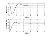
図4は、図1に示す構成で軸トルク制御がされている状態において、エンジンを始動した場合のシミュレーション波形である。ただし、軸トルク指令値は0[Nm]、エンジン回転数指令値は500[rpm]としている。従来の軸トルク制御では、図12に例を示すように、軸トルク、エンジン回転数が大きく振動していたが、本実施形態による軸トルク制御では振動が抑制され、軸トルク、エンジン回転数ともに指令値に追従している。 FIG. 4 is a simulation waveform when the engine is started in a state where the shaft torque control is performed in the configuration shown in FIG. However, the shaft torque command value is 0 [Nm] and the engine speed command value is 500 [rpm]. In the conventional shaft torque control, as shown in the example of FIG. 12, the shaft torque and the engine speed are greatly vibrated. However, in the shaft torque control according to the present embodiment, the vibration is suppressed, and both the shaft torque and the engine speed are Following the command value.
図5は、図13に示したガタの大きなクラッチを使用したエンジンベンチシステムに本実施形態を適用した場合のシミュレーション結果である。本実施形態によれば、ガタの大きなクラッチを使用したエンジンベンチシステムにおいても軸トルクやエンジン回転数が大きく振動することなく制御されている。 FIG. 5 shows a simulation result when the present embodiment is applied to the engine bench system using the clutch having a large backlash shown in FIG. According to this embodiment, even in an engine bench system that uses a clutch with a large backlash, the shaft torque and the engine speed are controlled without significant vibration.
実施形態(2)
図6は図1における軸トルク制御器10Aのブロック構成を示す。図6のブロック構成が図2の構成と異なる部分は、軸トルク検出器が適用できないシステムに適用する場合、軸トルクメータ5による軸トルク検出に代えて、軸トルクオブザーバ30により軸トルクを推定する点にある。
Embodiment (2)
FIG. 6 shows a block configuration of the
図7は軸トルクオブザーバ30の回路構成図を示し、図3の外乱オブザーバと同等の構成とするが、「greac」は軸トルクオブザーバの応答速度を決める定数(単位:1/秒)である。
FIG. 7 shows a circuit configuration diagram of the
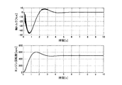
図8は、図6の軸トルク制御器により軸トルク制御がされている状態において、エンジンを始動した場合のシミュレーション波形である.ただし、軸トルク指令値は0[Nm]、エンジン回転数指令値は500[rpm]としている。本実施形態においても軸トルク制御で振動が抑制され、軸トルク、エンジン回転数ともに指令値に追従している。 FIG. 8 is a simulation waveform when the engine is started in a state where the shaft torque control is performed by the shaft torque controller of FIG. However, the shaft torque command value is 0 [Nm] and the engine speed command value is 500 [rpm]. Also in this embodiment, the vibration is suppressed by the shaft torque control, and both the shaft torque and the engine speed follow the command value.
図9は、図13に示したガタの大きなクラッチを使用したエンジンベンチシステムに本実施形態を適用した場合のシミュレーション結果である。本実施形態においても、ガタの大きなクラッチを使用したエンジンベンチシステムにおいても軸トルクやエンジン回転数が大きく振動することなく制御されている。 FIG. 9 shows a simulation result when the present embodiment is applied to the engine bench system using the clutch having a large backlash shown in FIG. Also in this embodiment, even in an engine bench system using a large loose clutch, the shaft torque and engine speed are controlled without significant vibration.
以上までの実施形態(1)、(2)では、エンジンベンチシステムに適用した動力計の軸トルク制御装置であるが、産業用ロボットなどに見られる2慣性系動力システムまたは3慣性系以上のシステムを2慣性系に近似可能な動力システムにおける軸トルク制御に適用して同等の作用効果を得ることができる。 In the embodiments (1) and (2) described above, the shaft torque control device for a dynamometer applied to an engine bench system is used. However, a two-inertia power system or a system of three or more inertia systems found in industrial robots or the like. Can be applied to shaft torque control in a power system that can be approximated to a two-inertia system, and equivalent effects can be obtained.
これらのシステムの場合、負荷側モータをエンジンとみなし、駆動モータを動力計とみなし、負荷側モータが速度制御されている場合に駆動モータに対するトルク外乱を「外乱オブザーバ」により推定して駆動モータのトルク指令値にフィードバックすることにより駆動モータの加速度制御系を構成する。さらに、軸トルク検出器により検出された軸トルク検出値を共振比制御理論に基づいて決定されるゲインで駆動モータの加速度指令値としてフィードバックし、さらにまた、駆動モータの速度検出値を所定の共振抑制効果が得られるように決定したゲインで駆動モータの加速度指令値にフィ−ドバックし、及び、軸トルク指令値に軸トルク検出値が追従するように比例積分制御系を構成する。 In these systems, the load-side motor is regarded as an engine, the drive motor is regarded as a dynamometer, and when the load-side motor is speed-controlled, torque disturbance to the drive motor is estimated by a “disturbance observer” and the drive motor An acceleration control system of the drive motor is configured by feeding back to the torque command value. Furthermore, the detected value of the shaft torque detected by the shaft torque detector is fed back as an acceleration command value of the drive motor with a gain determined based on the resonance ratio control theory, and the speed detection value of the drive motor is also given a predetermined resonance. A proportional-integral control system is configured so that the acceleration command value of the drive motor is fed back with a gain determined so as to obtain a suppression effect, and the shaft torque detection value follows the shaft torque command value.
また、システムが「軸トルク検出器」を適用できない場合において、実施形態(2)と同様に、外乱オブザーバ理論により軸トルクを推定する軸トルクオブザーバを設け、その軸トルク推定値を軸トルク検出値として利用する。 Further, when the system cannot apply the “shaft torque detector”, similarly to the embodiment (2), a shaft torque observer is provided for estimating the shaft torque by the disturbance observer theory, and the estimated shaft torque value is used as the detected shaft torque value. Use as
1 エンジン
2 クラッチ
5 軸トルクメータ
6 動力計
7 回転数検出器
8 エンジン制御器
10 動力計制御器
10A 軸トルク制御器
11 インバータ
21 外乱オブザーバ
22 軸トルク検出器
23 比例積分制御器
26,28 係数器
30 軸トルクオブザーバ
50 エンジンベンチシステムの機械モデル
DESCRIPTION OF
Claims (4)
前記駆動モータに対するトルク外乱を外乱オブザーバにより推定して該駆動モータのトルク指令値にフィードバックする駆動モータの加速度制御系と、
前記駆動モータの軸トルク指令値と軸トルク検出値との偏差を比例積分演算して該駆動モータの加速度指令値を得る比例積分制御系と、
前記駆動モータの軸トルク検出値を共振比制御理論に基づいて決定したゲインで該駆動モータの加速度指令値にフィードバックする手段と、
前記駆動モータの速度検出値を所定のゲインで該駆動モータの加速度指令値にフィ−ドバックする手段と、
を備えたことを特徴とする軸トルク制御装置。 Power that can be approximated to a two-inertia system or a two-inertia system, comprising a mechanical system in which a load-side motor and a drive motor are axially coupled, and a control system that performs rotational speed control of the load-side motor and shaft torque control of the drive motor A shaft torque control device for a system,
An acceleration control system of the drive motor that estimates a torque disturbance to the drive motor by a disturbance observer and feeds back to the torque command value of the drive motor;
A proportional-integral control system that obtains an acceleration command value of the drive motor by performing a proportional-integral calculation of a deviation between the shaft torque command value of the drive motor and a detected shaft torque value;
Means for feeding back the shaft torque detection value of the drive motor to the acceleration command value of the drive motor with a gain determined based on a resonance ratio control theory;
Means for feeding back the speed detection value of the drive motor to the acceleration command value of the drive motor with a predetermined gain;
A shaft torque control device comprising:
前記動力計に対するトルク外乱を外乱オブザーバにより推定して該動力計のトルク指令値にフィードバックする駆動モータの加速度制御系と、
前記動力計の軸トルク指令値と軸トルク検出値との偏差を比例積分演算して該動力計の加速度指令値を得る比例積分制御系と、
前記動力計の軸トルク検出値を共振比制御理論に基づいて決定したゲインで該動力計の加速度指令値にフィードバックする手段と、
前記動力計の速度検出値を所定のゲインで該動力計の加速度指令値にフィ−ドバックする手段と、
を備えたことを特徴とする軸トルク制御装置。 A shaft of an engine bench system that can be approximated to a two-inertia system or a two-inertia system, comprising a mechanical system in which an engine and a dynamometer are shaft-coupled, and a control system that performs engine speed control and shaft torque control of the dynamometer A torque control device,
An acceleration control system of a drive motor that estimates a torque disturbance for the dynamometer by a disturbance observer and feeds back to the torque command value of the dynamometer;
A proportional-integral control system that obtains an acceleration command value of the dynamometer by performing a proportional-integral calculation of a deviation between the shaft torque command value of the dynamometer and the detected shaft torque value;
Means for feeding back the shaft torque detection value of the dynamometer to an acceleration command value of the dynamometer with a gain determined based on a resonance ratio control theory;
Means for feeding back the speed detection value of the dynamometer to an acceleration command value of the dynamometer with a predetermined gain;
A shaft torque control device comprising:
Priority Applications (1)
| Application Number | Priority Date | Filing Date | Title |
|---|---|---|---|
| JP2010215210A JP5605127B2 (en) | 2010-09-27 | 2010-09-27 | Shaft torque control device |
Applications Claiming Priority (1)
| Application Number | Priority Date | Filing Date | Title |
|---|---|---|---|
| JP2010215210A JP5605127B2 (en) | 2010-09-27 | 2010-09-27 | Shaft torque control device |
Publications (3)
| Publication Number | Publication Date |
|---|---|
| JP2012068199A JP2012068199A (en) | 2012-04-05 |
| JP2012068199A5 JP2012068199A5 (en) | 2013-10-24 |
| JP5605127B2 true JP5605127B2 (en) | 2014-10-15 |
Family
ID=46165638
Family Applications (1)
| Application Number | Title | Priority Date | Filing Date |
|---|---|---|---|
| JP2010215210A Active JP5605127B2 (en) | 2010-09-27 | 2010-09-27 | Shaft torque control device |
Country Status (1)
| Country | Link |
|---|---|
| JP (1) | JP5605127B2 (en) |
Cited By (3)
| Publication number | Priority date | Publication date | Assignee | Title |
|---|---|---|---|---|
| JP2016133377A (en) * | 2015-01-19 | 2016-07-25 | 株式会社明電舎 | Dynamometer system control device |
| WO2017082143A1 (en) * | 2015-11-09 | 2017-05-18 | 株式会社明電舎 | Dynamometer-system dynamo control device and engine starting method therefor |
| WO2018190303A1 (en) * | 2017-04-14 | 2018-10-18 | 株式会社明電舎 | Electric inertia control device |
Families Citing this family (7)
| Publication number | Priority date | Publication date | Assignee | Title |
|---|---|---|---|---|
| CN102799192A (en) * | 2012-08-14 | 2012-11-28 | 中国科学院国家天文台南京天文光学技术研究所 | Nonlinear disturbance simulation and detection control system for astronomical telescope |
| JP6107294B2 (en) * | 2013-03-26 | 2017-04-05 | 株式会社明電舎 | Control device for each wheel independent drive cart |
| CN103969048B (en) * | 2014-02-18 | 2016-12-07 | 潍柴动力股份有限公司 | A kind of point selection of operating conditions method and device |
| JP2017034936A (en) * | 2015-08-05 | 2017-02-09 | 国立大学法人長岡技術科学大学 | Motor control apparatus, motor device, and motor control method |
| KR102118184B1 (en) * | 2018-01-10 | 2020-06-02 | 서울과학기술대학교 산학협력단 | Method and Apparatus for Robust Emulation of Mechanical Load by using Disturbance Observer |
| JP6962893B2 (en) * | 2018-10-04 | 2021-11-05 | 株式会社神戸製鋼所 | Vibration suppression device, vibration suppression method and program |
| CN113624500B (en) * | 2021-07-28 | 2024-03-01 | 广西玉柴机器股份有限公司 | Diesel engine emission fault torque limiting timing acceleration method and system |
Family Cites Families (15)
| Publication number | Priority date | Publication date | Assignee | Title |
|---|---|---|---|---|
| JP2737064B2 (en) * | 1991-10-08 | 1998-04-08 | 東洋電機製造株式会社 | Control device |
| JPH06217579A (en) * | 1993-01-12 | 1994-08-05 | Fuji Electric Co Ltd | Motor controller |
| JP3339246B2 (en) * | 1994-04-04 | 2002-10-28 | 株式会社明電舎 | Vibration Suppression Device for Two-Inertial Resonant System by Low Inertia Control |
| JPH09121580A (en) * | 1995-10-26 | 1997-05-06 | Meidensha Corp | Vibration suppressor of two-inertia resonance system by low inertia control |
| JP3687305B2 (en) * | 1997-09-30 | 2005-08-24 | 株式会社明電舎 | Dynamometer system |
| JP4151401B2 (en) * | 2002-12-19 | 2008-09-17 | 株式会社安川電機 | Servo control device |
| JP4655677B2 (en) * | 2005-02-28 | 2011-03-23 | シンフォニアテクノロジー株式会社 | Power transmission system test apparatus and control method thereof |
| JP5084232B2 (en) * | 2006-02-03 | 2012-11-28 | Juki株式会社 | Synchronous anti-vibration control device for positioning device |
| JP4784451B2 (en) * | 2006-09-12 | 2011-10-05 | 株式会社明電舎 | Control method and apparatus for engine bench system |
| JP2008145354A (en) * | 2006-12-12 | 2008-06-26 | Toyota Motor Corp | Method and apparatus for testing engine |
| JP2008203052A (en) * | 2007-02-20 | 2008-09-04 | Meidensha Corp | Control device for engine bench system |
| JP4788656B2 (en) * | 2007-05-16 | 2011-10-05 | 株式会社明電舎 | Power test system |
| JP5141378B2 (en) * | 2008-05-28 | 2013-02-13 | 株式会社明電舎 | Electric inertia control system of dynamometer |
| JP5088414B2 (en) * | 2008-08-26 | 2012-12-05 | 株式会社明電舎 | Disturbance suppression device and disturbance suppression method for electric motor |
| JP5245668B2 (en) * | 2008-09-18 | 2013-07-24 | 株式会社明電舎 | Control method of engine bench system |
-
2010
- 2010-09-27 JP JP2010215210A patent/JP5605127B2/en active Active
Cited By (9)
| Publication number | Priority date | Publication date | Assignee | Title |
|---|---|---|---|---|
| JP2016133377A (en) * | 2015-01-19 | 2016-07-25 | 株式会社明電舎 | Dynamometer system control device |
| WO2016117394A1 (en) * | 2015-01-19 | 2016-07-28 | 株式会社明電舎 | Control device for dynamometer system |
| US10371589B2 (en) | 2015-01-19 | 2019-08-06 | Meidensha Corporation | Control device for dynamometer system |
| WO2017082143A1 (en) * | 2015-11-09 | 2017-05-18 | 株式会社明電舎 | Dynamometer-system dynamo control device and engine starting method therefor |
| JP2017090195A (en) * | 2015-11-09 | 2017-05-25 | 株式会社明電舎 | Dynamo controller of dynamometer system, and engine starting method thereof |
| US10190944B2 (en) | 2015-11-09 | 2019-01-29 | Meidensha Corporation | Dynamometer-system dynamo control device and engine starting method therefor |
| WO2018190303A1 (en) * | 2017-04-14 | 2018-10-18 | 株式会社明電舎 | Electric inertia control device |
| JP2018179802A (en) * | 2017-04-14 | 2018-11-15 | 株式会社明電舎 | Electric inertia control device |
| US10895511B2 (en) | 2017-04-14 | 2021-01-19 | Meidensha Corporation | Dynamometer system |
Also Published As
| Publication number | Publication date |
|---|---|
| JP2012068199A (en) | 2012-04-05 |
Similar Documents
| Publication | Publication Date | Title |
|---|---|---|
| JP5605127B2 (en) | Shaft torque control device | |
| JP5214578B2 (en) | Power unit control unit | |
| JP5326429B2 (en) | Electric motor pulsation suppression device | |
| US10414287B2 (en) | Control apparatus for rotary electric machines | |
| WO2016117394A1 (en) | Control device for dynamometer system | |
| WO2002038332A1 (en) | Servocontrol device | |
| WO2017082143A1 (en) | Dynamometer-system dynamo control device and engine starting method therefor | |
| JP2011257205A (en) | Axial torque controller for dynamometer system | |
| JP2009042985A (en) | Motor control unit and motor control method | |
| JP4645231B2 (en) | Power transmission system test apparatus and control method thereof | |
| JP4914979B2 (en) | Motor control device and motor control method | |
| WO2017188271A1 (en) | Device for controlling dynamometer of test system | |
| JP4591177B2 (en) | Engine test equipment | |
| WO2018190303A1 (en) | Electric inertia control device | |
| WO2020194637A1 (en) | Control method and control device for electric vehicle | |
| JP2008145354A (en) | Method and apparatus for testing engine | |
| JP2013257857A (en) | Controller of mechanical device, mechanical system, and method of controlling mechanical device | |
| JP2014174107A (en) | Power system testing device | |
| JP2013053978A (en) | Control device of engine bench system | |
| JPWO2020100268A1 (en) | Electric vehicle control method and control device | |
| JP5895405B2 (en) | Control device for engine bench system | |
| JP7317597B2 (en) | Control device | |
| JP5850179B2 (en) | Motor control device and motor control method | |
| WO2015186616A1 (en) | Control device for chassis dynamometer | |
| JP6724412B2 (en) | Controller for engine bench system |
Legal Events
| Date | Code | Title | Description |
|---|---|---|---|
| A521 | Written amendment |
Free format text: JAPANESE INTERMEDIATE CODE: A523 Effective date: 20130906 |
|
| A621 | Written request for application examination |
Free format text: JAPANESE INTERMEDIATE CODE: A621 Effective date: 20130906 |
|
| RD02 | Notification of acceptance of power of attorney |
Free format text: JAPANESE INTERMEDIATE CODE: A7422 Effective date: 20130906 |
|
| A977 | Report on retrieval |
Free format text: JAPANESE INTERMEDIATE CODE: A971007 Effective date: 20140718 |
|
| TRDD | Decision of grant or rejection written | ||
| A01 | Written decision to grant a patent or to grant a registration (utility model) |
Free format text: JAPANESE INTERMEDIATE CODE: A01 Effective date: 20140729 |
|
| A61 | First payment of annual fees (during grant procedure) |
Free format text: JAPANESE INTERMEDIATE CODE: A61 Effective date: 20140811 |
|
| R150 | Certificate of patent or registration of utility model |
Ref document number: 5605127 Country of ref document: JP Free format text: JAPANESE INTERMEDIATE CODE: R150 |