JP5605128B2 - Dynamometer shaft torque control device - Google Patents
Dynamometer shaft torque control device Download PDFInfo
- Publication number
- JP5605128B2 JP5605128B2 JP2010215211A JP2010215211A JP5605128B2 JP 5605128 B2 JP5605128 B2 JP 5605128B2 JP 2010215211 A JP2010215211 A JP 2010215211A JP 2010215211 A JP2010215211 A JP 2010215211A JP 5605128 B2 JP5605128 B2 JP 5605128B2
- Authority
- JP
- Japan
- Prior art keywords
- dynamometer
- engine
- shaft
- shaft torque
- torque
- Prior art date
- Legal status (The legal status is an assumption and is not a legal conclusion. Google has not performed a legal analysis and makes no representation as to the accuracy of the status listed.)
- Active
Links
Images


Description
本発明は、動力計の軸トルク制御装置に係り、特に中間軸を持つエンジンベンチシステムのカップリングによる共振抑制とクラッチによる共振抑制に関するものである。 The present invention relates to a shaft torque control device for a dynamometer, and particularly to resonance suppression by coupling and resonance suppression by a clutch of an engine bench system having an intermediate shaft.
図14に一般的なエンジンベンチシステムの機械系構成と制御系構成を示す。機械系は、供試対象となるエンジン1にクラッチ2と変速機(MT)3およびプロペラシャフト4を結合し、このプロペラシャフト4に軸トルクメータ5を介して動力計6を結合する。動力計6の回転軸にはその回転数検出手段としてのインクリメンタルエンコーダ7を結合する。制御系は、エンジン1を制御するエンジン制御器8とスロットルアクチェータ9を設け、動力計6を制御する動力計制御器10とインバータ(電力変換器)11を設ける。
FIG. 14 shows a mechanical system configuration and a control system configuration of a general engine bench system. In the mechanical system, a
動力計制御器10にはエンコーダ7で検出する回転数や軸トルクメータ5で検出する軸トルクがフィードバックされ、動力計の軸トルクや回転数が制御される。エンジン1もエンジン制御器8により出力などが制御される。
The
図15は図14に示したエンジンベンチシステムの機械モデルを示す。一般的なエンジンベンチシステムでは、プロペラシャフト4の慣性モーメントが動力計6やエンジン1の慣性モーメントと比較して小さく、また、プロペラシャフト4などのねじれ剛性はクラッチ2の捩れ剛性よりも非常に大きいため、図15のように2慣性系モデル(2個の慣性モーメントとそれらを結合する弾性要素からなるモデル)とみなすことができる。
FIG. 15 shows a mechanical model of the engine bench system shown in FIG. In a general engine bench system, the moment of inertia of the
例えば、特許文献1では、2慣性系とみなすことのできる図14の機械系構成のエンジンベンチシステムにおいて、動力計6で軸トルク制御をする場合の、動力計トルク制御方法とその装置を提案している。
For example,
図16に別の形態のエンジンベンチシステムの機械構成と制御系構成を示し、制御系構成は図14と同様である。図16の機械系はエンジン1側の出力軸を中間軸12で延長し、この中間軸12の先端部をカップリング13で動力計6側に軸結合する。
FIG. 16 shows a mechanical configuration and a control system configuration of another form of engine bench system, and the control system configuration is the same as FIG. In the mechanical system of FIG. 16, the output shaft on the
この機械構成とする理由は、エンジンを特殊環境下(低温や低圧など)におく場合には、エンジンのみを環境室に入れるために(中間軸)や(カップリング)で軸延長を得るためである。図16に示したエンジンベンチシステムでは、中間軸の慣性モーメントがエンジンや動力計の慣性モーメントと比較して必ずしも小さくはなく、また、カップリングの捩れ剛性がクラッチの捩れ剛性と比較して十分硬くはなっていない。そのため、図16に示したエンジンベンチシステムの機械モデルを図17に示すように、3慣性系モデルとして考えなければならない。 The reason for this mechanical configuration is that when the engine is placed in a special environment (low temperature, low pressure, etc.), only the engine is placed in the environmental chamber (intermediate shaft) or (coupling) to obtain a shaft extension. is there. In the engine bench system shown in FIG. 16, the moment of inertia of the intermediate shaft is not necessarily smaller than the moment of inertia of the engine or dynamometer, and the torsional rigidity of the coupling is sufficiently harder than the torsional rigidity of the clutch. It is not. Therefore, the machine model of the engine bench system shown in FIG. 16 must be considered as a three-inertia system model as shown in FIG.
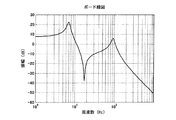
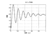
図18は中間軸を持つエンジンベンチシステムのトルク応答特性(動力計トルク指令→軸トルク検出特性)のボード線図を示し、図19はステップ応答波形を示し、カップリングによる共振点(図18では約100Hz)と、クラッチによる共振点(図18では約10Hz)の2つの大きな共振ゲインを持つ共振点が現れる。 18 shows a Bode diagram of torque response characteristics (dynamometer torque command → shaft torque detection characteristics) of an engine bench system having an intermediate shaft, FIG. 19 shows a step response waveform, and a resonance point by coupling (in FIG. 18 ) A resonance point having two large resonance gains appears (about 100 Hz) and a resonance point by the clutch (about 10 Hz in FIG. 18 ).
図19に示すように、中間軸を持つエンジンベンチシステムの動力計トルク指令に対する軸トルク検出値のステップ応答は、カップリングによる共振(図19では100Hz)が軸トルク検出波形に重畳し、エンジン特性を正確に測定することが困難となる。 As shown in FIG. 19, the step response of the detected shaft torque value to the dynamometer torque command of the engine bench system having the intermediate shaft is based on the engine characteristic by the resonance (100 Hz in FIG. 19) being superimposed on the detected shaft torque waveform. It becomes difficult to measure accurately.
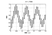
図20および図21は、中間軸を持つエンジンベンチシステムの軸トルク制御器を特許文献1の制御手法で構成した場合の制御特性を示す。図20は軸トルク指令値に対する軸トルク検出値のボード線図、図21は軸トルク指令値に対する軸トルク検出値のステップ応答である。図20のボード線図では、クラッチの共振点である10Hz付近まで指令値通りになるように制御できているが、図21を見ると、100Hzのカップリングの共振点で制御が不安定化し、次第に発散していることがわかる。そのため、特許文献1の制御手法は中間軸を持つエンジンベンチシステムには適用できない。
20 and 21 show control characteristics when the shaft torque controller of the engine bench system having the intermediate shaft is configured by the control method of
本発明の目的は、中間軸を持つエンジンベンチシステムにおけるカップリングのばね剛性に起因する共振を抑制でき、さらにはクラッチのばね剛性に起因する共振も抑制できる動力計の軸トルク制御装置を提供することにある。 An object of the present invention is to provide a shaft torque control device for a dynamometer that can suppress resonance caused by the spring stiffness of a coupling in an engine bench system having an intermediate shaft, and can further suppress resonance caused by the spring stiffness of a clutch. There is.
本発明は、前記の課題を解決するため、中間軸を持つエンジンベンチシステムにおける動力計トルク指令値として、軸トルク検出値を低域通過フィルタ(LPF)を通して動力計トルク指令値に加算して新たな動力計トルク指令値とする構成、軸トルク検出値を無駄時間要素(TD)を通して動力計トルク指令値に加算して新たな動力計トルク指令値とする構成、さらに低域通過フィルタ(LPF)または無駄時間要素(TD)を通した動力計の軸トルク検出値を高域通過フィルタ(HPF)を通して動力計トルク指令値に加算して新たな動力計トルク指令値とする構成、さらにまた動力計トルク指令値に対して第1の低域通過フィルタ(LPF)を通した軸トルク検出値でフィードバック制御する軸トルク制御器と、第2の低域通過フィルタ(LPF)または無駄時間要素(TD)を通した軸トルク検出値を前記軸トルク制御器の制御出力に所定の比率で加算して新たな動力計トルク指令値とする構成としたもので、以下の構成を特徴とする。 In order to solve the above problems, the present invention adds a shaft torque detection value to a dynamometer torque command value through a low-pass filter (LPF) as a dynamometer torque command value in an engine bench system having an intermediate shaft. A configuration that provides a new dynamometer torque command value, a configuration that adds a shaft torque detection value to a dynamometer torque command value through a dead time element (TD), and a new dynamometer torque command value, and a low-pass filter (LPF) Alternatively, a configuration in which the shaft torque detection value of the dynamometer that has passed the dead time element (TD) is added to the dynamometer torque command value through a high-pass filter (HPF) to obtain a new dynamometer torque command value, and also the dynamometer A shaft torque controller that feedback-controls the torque command value with a shaft torque detection value that has passed through a first low-pass filter (LPF), and a second low-pass filter (LPF) or the dead time element (TD) is added to the control output of the shaft torque controller at a predetermined ratio to obtain a new dynamometer torque command value. It is characterized by the configuration of
(1)エンジンの出力軸に設けた中間軸をカップリングを介して動力計に結合した機械系構成とし、エンジンはエンジン制御指令に従って出力制御し、動力計は軸トルク指令値に従って軸トルク制御する制御系構成としたエンジンベンチシステムにおいて、
動力計の軸トルク検出値を低域通過フィルタを通して動力計トルク指令値に加算して新たな動力計トルク指令値とし、該低域通過フィルタは前記カップリングのばね剛性により発生する共振周波数における位相遅れを設定値近くにした構成を特徴とする。
(1) A mechanical system configuration in which an intermediate shaft provided on the output shaft of the engine is coupled to a dynamometer through a coupling, the engine performs output control according to an engine control command, and the dynamometer performs shaft torque control according to a shaft torque command value. In the engine bench system with a control system configuration,
A dynamometer shaft torque detection value is added to a dynamometer torque command value through a low-pass filter to obtain a new dynamometer torque command value. The low-pass filter has a phase at a resonance frequency generated by the spring stiffness of the coupling. It features a configuration in which the delay is close to the set value.
(2)エンジンの出力軸に設けた中間軸をカップリングを介して動力計に結合した機械系構成とし、エンジンはエンジン制御指令に従って出力制御し、動力計は軸トルク指令値に従って軸トルク制御する制御系構成としたエンジンベンチシステムにおいて、
動力計の軸トルク検出値を無駄時間要素(TD)を通して動力計トルク指令値に加算して新たな動力計トルク指令値とし、該無駄時間要素は前記カップリングのばね剛性による共振周波数において位相遅れが設定値近くになる無駄時間長にした構成を特徴とする。
(2) An intermediate shaft provided on the output shaft of the engine is coupled to a dynamometer through a coupling. The engine performs output control according to an engine control command, and the dynamometer performs shaft torque control according to a shaft torque command value. In the engine bench system with a control system configuration,
The detected value of the shaft torque of the dynamometer is added to the dynamometer torque command value through the dead time element (TD) to obtain a new dynamometer torque command value, and the dead time element is a phase lag at the resonance frequency due to the spring stiffness of the coupling. It is characterized by a configuration in which the dead time length becomes close to the set value.
(3)エンジンの出力軸に設けた中間軸をカップリングを介して動力計に結合した機械系構成とし、エンジンはエンジン制御指令に従って出力制御し、動力計は軸トルク指令値に従って軸トルク制御する制御系構成としたエンジンベンチシステムにおいて、
低域通過フィルタ(LPF)または無駄時間要素(TD)を通した動力計の軸トルク検出値を、高域通過フィルタ(HPF)を通して動力計トルク指令値に加算して新たな動力計トルク指令値とし、
前記低域通過フィルタは前記カップリングのばね剛性により発生する共振周波数における位相遅れを設定値近くにし、
前記無駄時間要素は前記カップリングのばね剛性による共振周波数において位相遅れが設定値近くになる無駄時間長にし、
前記高域通過フィルタの特性周波数は前記カップリングのばね剛性に起因する共振周波数より低い範囲とした構成を特徴とする。
(3) A mechanical system configuration in which an intermediate shaft provided on the output shaft of the engine is coupled to a dynamometer through a coupling, the engine performs output control according to an engine control command, and the dynamometer performs shaft torque control according to a shaft torque command value. In the engine bench system with a control system configuration,
The new dynamometer torque command value is obtained by adding the shaft torque detection value of the dynamometer that has passed through the low-pass filter (LPF) or dead time element (TD) to the dynamometer torque command value through the high-pass filter (HPF). age,
The low-pass filter makes the phase lag at the resonance frequency generated by the spring stiffness of the coupling close to a set value,
The dead time element is a dead time length in which the phase delay is close to a set value at the resonance frequency due to the spring stiffness of the coupling,
The characteristic frequency of the high-pass filter is characterized in that it is in a range lower than the resonance frequency due to the spring stiffness of the coupling.
(4)エンジンのクラッチを通した出力軸に設けた中間軸をカップリングを介して動力計に結合した機械系構成とし、エンジンはエンジン制御指令に従って出力制御し、動力計は軸トルク指令値に従って軸トルク制御する制御系構成としたエンジンベンチシステムにおいて、
動力計トルク指令値に対して第1の低域通過フィルタ(LPF)を通した軸トルク検出値との偏差でPID演算してトルク制御出力を求める軸トルク制御器と、
第2の低域通過フィルタ(LPF)または無駄時間要素(TD)を通した軸トルク検出値を前記軸トルク制御器の制御出力に所定の比率で加算して新たな動力計トルク指令値とし、
前記軸トルク制御器は、次式のPID演算でトルク制御出力T3Aを求め、
T3A=(Ki/s)*(T23ref−T23det)−(Kp+s*Kd)/(a2*s*s+a1*s+1)*T23det
ただし、T23ref:軸トルク指令、T23det:軸トルク検出値の第1の低域通過フィルタ(LPF)出力、Ki:積分係数、Kp:比例係数、Kd:微分係数、a1、a2:比例・微分要素のフィルタ係数
前記第2の低域通過フィルタは前記カップリングのばね剛性により発生する共振周波数における位相遅れを設定値近くにし、前記無駄時間要素は前記カップリングのばね剛性による共振周波数において位相遅れが設定値近くになる無駄時間長にした構成を特徴とする。
(4) A mechanical system configuration in which an intermediate shaft provided on an output shaft through an engine clutch is coupled to a dynamometer through a coupling, the engine performs output control according to an engine control command, and the dynamometer according to a shaft torque command value In an engine bench system with a control system configuration that controls shaft torque,
A shaft torque controller that calculates a torque control output by performing PID calculation on a deviation from a shaft torque detection value that has passed through a first low-pass filter (LPF) with respect to a dynamometer torque command value;
The shaft torque detection value that has passed through the second low-pass filter (LPF) or dead time element (TD) is added to the control output of the shaft torque controller at a predetermined ratio to obtain a new dynamometer torque command value,
The shaft torque controller obtains the torque control output T3A by the PID calculation of the following equation,
T3A = (Ki / s) * (T23ref−T23det) − (Kp + s * Kd) / (a2 * s * s + a1 * s + 1) * T23det
Where T23ref: shaft torque command, T23det: first low-pass filter (LPF) output of shaft torque detection value, Ki: integral coefficient, Kp: proportional coefficient, Kd: differential coefficient, a1, a2: proportional / differential element The filter coefficient of the second low-pass filter is such that the phase lag at the resonance frequency generated by the spring stiffness of the coupling is close to a set value, and the dead time element has a phase lag at the resonance frequency due to the spring stiffness of the coupling. It is characterized by a configuration with a dead time length that is close to the set value.
以上のとおり、本発明によれば、軸トルク検出値を低域通過フィルタ(LPF)や無駄時間要素(TD)通して動力計トルク指令値に加算して新たな動力計トルク指令値とすることでカップリングのばね剛性に起因する共振を抑制できる。 As described above, according to the present invention, the shaft torque detection value is added to the dynamometer torque command value through the low-pass filter (LPF) or the dead time element (TD) to obtain a new dynamometer torque command value. Thus, resonance caused by the spring stiffness of the coupling can be suppressed.
さらに、低域通過フィルタ(LPF)または無駄時間要素(TD)を通した動力計の軸トルク検出値を高域通過フィルタ(HPF)を通して動力計トルク指令値に加算して新たな動力計トルク指令値とし、該高域通過フィルタの特性周波数は前記カップリングのばね剛性に起因する共振周波数より低い範囲とすることで、動力計側からのアシスト無しにエンジンの始動が可能となる。 Furthermore, a new dynamometer torque command is obtained by adding the shaft torque detection value of the dynamometer that has passed through the low-pass filter (LPF) or the dead time element (TD) to the dynamometer torque command value through the high-pass filter (HPF). By setting the value and the characteristic frequency of the high-pass filter in a range lower than the resonance frequency due to the spring stiffness of the coupling, the engine can be started without assistance from the dynamometer side.
さらにまた、動力計トルク指令値に対して第1の低域通過フィルタ(LPF)を通した軸トルク検出値でフィードバック制御する軸トルク制御器と、第2の低域通過フィルタ(LPF)または無駄時間要素(TD)を通した軸トルク検出値を前記軸トルク制御器の制御出力に所定の比率で加算して新たな動力計トルク指令値とすることで、カップリングによる共振抑制に加えて、クラッチによる共振抑制もできる。 Furthermore, a shaft torque controller that performs feedback control with a shaft torque detection value that has passed through the first low-pass filter (LPF) with respect to the dynamometer torque command value, and a second low-pass filter (LPF) or wasteful In addition to resonance suppression by coupling by adding the shaft torque detection value through the time element (TD) to the control output of the shaft torque controller at a predetermined ratio to obtain a new dynamometer torque command value, The resonance can be suppressed by the clutch.
実施形態(1)
図1は本実施形態による制御系の構成を示す。この構成は、図16に示す中間軸を持つ3慣性系のエンジンベンチシステムにおける動力計6のトルク制御に、軸トルク(T23)検出値をある特性の低域通過フィルタ(LPF)21を通して加算器(Sum)22にフィードバックし、動力計トルク指令(T3ref)に加算して新たな動力計トルク指令とする。この構成により、中間軸を持つエンジンベンチシステムにおいて、動力計6と中間軸12を結合するカップリング13による共振を抑制して動力計6を安定制御するものである。
Embodiment (1)
FIG. 1 shows the configuration of a control system according to this embodiment. In this configuration, an adder is added to the torque control of the dynamometer 6 in the three-inertia engine bench system having an intermediate shaft shown in FIG. (Sum) 22 is fed back and added to the dynamometer torque command (T3ref) to obtain a new dynamometer torque command. With this configuration, in an engine bench system having an intermediate shaft, the dynamometer 6 is stably controlled by suppressing resonance by the coupling 13 that couples the dynamometer 6 and the intermediate shaft 12.
図1中、20(MIM3J)は、図16に示す中間軸を持つエンジンベンチシステムの機械モデルであり、本実施形態では図2にブロック構成で示す3慣性系機械モデルで置き換えることでシミュレーションを可能とするが、実際のシステムの場合は図16の機械系と制御系をもつ構成にされる。図2中の各ブロックにおけるエンジン1、中間軸12および動力計6における定数等は、図17中に示すように、以下のものとする。なお、sはラプラス演算子である。
In FIG. 1, 20 (MIM3J) is a mechanical model of the engine bench system having the intermediate shaft shown in FIG. 16, and in this embodiment, the simulation can be performed by replacing it with the three-inertia mechanical model shown in the block configuration in FIG. However, an actual system is configured to have the mechanical system and control system shown in FIG. Constants in the
J1=エンジン慣性モーメント、J2=中間軸慣性モーメント、J3=動力計慣性モーメント、K12=クラッチばね剛性、K23=カップリングばね剛性、T1=エンジントルク、T3=動力計トルク、T23=軸トルク(カップリング)、T12=軸トルク(クラッチ)、ω1=エンジン角速度、ω2=中間軸角速度、ω3=動力計角速度
なお、低域通過フィルタ(LPF)21の特性は、カップリング13による共振周波数において位相遅れが設定値近く、例えば約45度になるようにする。カップリング13のばね剛性に起因する共振周波数が、例えば、図18に示したような100Hzになっている場合、低域通過フィルタ(LPF)21の特性は、100Hzの1次低域通過フィルタや、200Hzの2次低域通過フィルタとする。
J1 = engine moment of inertia, J2 = intermediate shaft inertia moment, J3 = dynamometer moment of inertia, K12 = clutch spring stiffness, K23 = coupling spring stiffness, T1 = engine torque, T3 = dynamometer torque, T23 = shaft torque (cup) Ring), T12 = shaft torque (clutch), ω1 = engine angular speed, ω2 = intermediate shaft angular speed, ω3 = dynamometer angular speed Note that the characteristics of the low-pass filter (LPF) 21 are phase delayed at the resonance frequency due to the coupling 13 Is close to the set value, for example, about 45 degrees. For example, when the resonance frequency due to the spring rigidity of the coupling 13 is 100 Hz as shown in FIG. 18, the characteristic of the low-pass filter (LPF) 21 is a primary low-pass filter of 100 Hz, A 200 Hz secondary low-pass filter.
図3は、図1に示す構成で、動力計の軸トルク制御のシミュレーションを実行し、デジタル処理装置50によって計測およびデータ処理した動力計トルク指令(T3ref)に対する軸トルク(T23)の伝達関数のボード線図を示し、ステップ応答を図4に示す。これらの図から明らかなように、100Hz付近のカップリングによる共振ゲインが図18では約35dBあったものが、図3のように約5dB程度まで低減されている。そのため、図19では100Hzの振動が重畳していたが、図4では100Hzの振動はほとんど抑制され、クラッチによる振動(約7Hz)のみが現れている。
FIG. 3 shows the transfer function of the shaft torque (T23) with respect to the dynamometer torque command (T3ref) measured and data-processed by the
図5は本実施形態の制御系構成を示す。同図が図1と異なる構成は、図16に示す中間軸を持つ3慣性系のエンジンベンチシステムにおける動力計6のトルク制御に、軸トルク(T23)検出値を無駄時間要素(TD)23を通して加算器(Sum)24において動力計トルク指令(T3ref)に加算して新たな動力計トルク指令としている。この構成により、中間軸を持つエンジンベンチシステムにおいて、動力計6と中間軸12を結合するカップリング13のばね剛性に起因する共振を抑制して動力計6を安定に制御するものである。 FIG. 5 shows a control system configuration of the present embodiment. 1 is different from that shown in FIG. 1 in that the torque value of the dynamometer 6 in the three-inertia engine bench system having the intermediate shaft shown in FIG. adder (sum) is by adding the dynamometer torque command (T3ref) a new dynamometer torque command at 24. With this configuration, in an engine bench system having an intermediate shaft, resonance caused by the spring rigidity of the coupling 13 that couples the dynamometer 6 and the intermediate shaft 12 is suppressed and the dynamometer 6 is stably controlled.
なお、無駄時間要素(TD)23の無駄時間長は、カップリングによる共振周波数において位相遅れが設定値近く、例えば約45度になるようにする。カップリング13による共振周波数が、例えば、図18に示したような100Hzになっている場合、無駄時間要素(TD)の遅れを約1.25msとする。この構成をサンプル時間lmsのデジタル制御系で構成する場合にはサンプル遅れ要素(1/z)とすればよい。サンプル時間100μsのデジタル制御系で構成する場合には12サンプルの遅れ要素(1/z^12)とすればよい。 The dead time length of the dead time element (TD) 23 is set so that the phase delay is close to a set value, for example, about 45 degrees at the resonance frequency due to coupling. For example, when the resonance frequency by the coupling 13 is 100 Hz as shown in FIG. 18, the delay of the dead time element (TD) is set to about 1.25 ms. When this configuration is configured by a digital control system having a sampling time of 1 ms, a sample delay element (1 / z) may be used. In the case of a digital control system with a sample time of 100 μs, a 12-sample delay element (1 / z ^ 12) may be used.
図6は、図5に示す構成で、デジタル処理装置50によって計測およびデータ処理した動力計トルク指令(T3ref)に対する軸トルク(T23)の伝達関数のボード線図を示し、ステップ応答を図7に示す。これらの図から明らかなように、実施形態(1)と同等の振動抑制効果が得られている。
FIG. 6 shows a Bode diagram of the transfer function of the shaft torque (T23) with respect to the dynamometer torque command (T3ref) measured and processed by the
実施形態(3)
図8は本実施形態の制御系構成を示す。同図が図1や図5と異なる構成は、図16に示す中間軸を持つ3慣性系のエンジンベンチシステムにおける動力計6のトルク制御に、軸トルク(T23)検出値を遅れ要素(G)25及び、高域通過フィルタ(HPF)26を通して加算器(Sum)27において動力計トルク指令(T3ref)に加算して新たな動力計トルク指令とする。
Embodiment (3)
FIG. 8 shows a control system configuration of this embodiment. 1 differs from FIG. 1 and FIG. 5 in that the torque value of the dynamometer 6 in the three-inertia engine bench system having the intermediate shaft shown in FIG. 25 and an adder (Sum) 27 through a high-pass filter (HPF) 26 and added to the dynamometer torque command (T3ref) to obtain a new dynamometer torque command.
なお、遅れ要素(G)25は、実施形態(1)の低域通過フィルタ(LPF)21又は実施形態(2)の無駄時間要素(TD)23とする。また、高域通過フィルタ(HPF)26の特性周波数は、カップリングのばね剛性に起因する共振周波数より低い範囲で、制御が安定になるように適切に決める。 The delay element (G) 25 is the low-pass filter (LPF) 21 of the embodiment (1) or the dead time element (TD) 23 of the embodiment (2). Further, the characteristic frequency of the high-pass filter (HPF) 26 is appropriately determined so that the control becomes stable in a range lower than the resonance frequency caused by the spring stiffness of the coupling.
この構成により、中間軸を持つエンジンベンチシステムにおいて、遅れ要素(G)25の介在により動力計6と中間軸12を結合するカップリング13による共振を抑制すると共に、高域通過フィルタ(HPF)26の介在により軸トルク(T23)検出値の低域のフィードバックを抑制することで、動力計トルク指令がT3ref=0の場合においてもエンジンの始動を可能とする。 With this configuration, in an engine bench system having an intermediate shaft, resonance by the coupling 13 that couples the dynamometer 6 and the intermediate shaft 12 is suppressed by the intervention of the delay element (G) 25, and a high-pass filter (HPF) 26 is provided. By suppressing the low-frequency feedback of the detected value of the shaft torque (T23), the engine can be started even when the dynamometer torque command is T3ref = 0.
まず、図9は実施形態(1)、実施形態(2)におけるエンジントルクに対するエンジン回転数のステップ応答をデジタル処理装置50で計測およびデータ処理したものである。図9のように、実施形態(1)、実施形態(2)ではエンジンがトルクを発生しているにもかかわらず、エンジン回転数が上昇せず、動力計側からのアシスト無し(T3ref=0)にはエンジンが始動できない。これは、実施形態(1)、実施形態(2)では、軸トルク検出値(T23)の直流成分もフィードバックされることによる。
First, FIG. 9 is obtained by measuring and data processing the step response of the engine speed with respect to the engine torque in the embodiment (1) and the embodiment (2) by the
図10に本実施形態(3)におけるエンジントルクに対するエンジン回転数のステップ応答を示す。本実施形態(3)では高域通過フィルタ(HPF)26を通すことにより、軸トルク検出値の直流成分はフィードバックされない。そのため、図10のように、本実施形態(3)ではエンジンの回転数が上昇、すなわちエンジンの始動が可能となる。 FIG. 10 shows a step response of the engine speed with respect to the engine torque in the present embodiment (3). In this embodiment (3), the DC component of the detected shaft torque value is not fed back by passing through the high-pass filter (HPF) 26. Therefore, as shown in FIG. 10, in this embodiment (3), the engine speed increases, that is, the engine can be started.
実施形態(4)
図11は本実施形態の制御系構成を示す。同図が図1と異なる構成は、動力計6のトルク制御に、軸トルク(T23)検出値を低域通過フィルタ(TMLPF)28を通して軸トルク制御器(ATR)29へのフィードバック信号とし、このトルク制御器29のトルク制御出力T3Aを比率調整増幅器(ゲインK)30を通してトルク指令KT3Aとする。さらに、軸トルク(T23)検出値を遅れ要素(G)31及び比率調整増幅器(ゲインP)32を通して加算器(Sum)33においてトルク指令KT3Aに加算して新たなトルク指令値とする。なお、遅れ要素(G)31は、実施形態(1)の低域通過フィルタ(LPF)21又は実施形態(2)の無駄時間要素(TD)23とする。
Embodiment (4)
FIG. 11 shows a control system configuration of this embodiment. 1 is different from that shown in FIG. 1 in the torque control of the dynamometer 6, the detected value of the shaft torque (T 23) is used as a feedback signal to the shaft torque controller (ATR) 29 through the low-pass filter (TMLPF) 28. The torque control output T3A of the
軸トルク制御器(ATR)29は、特許文献1に記載される軸トルク制御器と同等の構成とする。特許文献1では、図15に示す2慣性系機械モデルの情報(エンジン慣性J1、動力計慣性J2、クラッチばね剛性K12、エンジン角速度ω1、動力計角速度ω2)を用いて、軸トルク指令T12rと軸トルク検出値T12との偏差でPID制御する軸トルク制御器とする。このときの動力計トルク制御信号T2の演算は、以下の積分要素と比例・微分要素で決定する。
The shaft torque controller (ATR) 29 has the same configuration as the shaft torque controller described in
T2=(Ki/s)*(T12r−T12)−(Kp+s*Kd)/(a2*s*s+a1*s+1)*T12…(式1)
ただし、Ki:積分係数、T12r:軸トルク指令値、T12:軸トルク検出値、Kp:比例係数、Kd:微分係数、a1、a2:比例・微分要素のフィルタ係数
ここで、軸トルク指令T12rを図11のT23refと置き換え、軸トルク検出値T12を図11のT23detに置き換え、動力計トルク制御信号T2を図11のトルク制御出力T3Aに置き換えると、(式1)は以下の(式2)となる。
T2 = (Ki / s) * (T12r−T12) − (Kp + s * Kd) / (a2 * s * s + a1 * s + 1) * T12 (Expression 1)
However, Ki: integral coefficient, T12r: shaft torque command value, T12: shaft torque detected value, Kp: proportional coefficient, Kd: differential coefficient, a1, a2: filter coefficient of proportional / differential element Here, the shaft torque command T12r is When T23ref in FIG. 11 is replaced, the detected shaft torque value T12 is replaced with T23det in FIG. 11, and the dynamometer torque control signal T2 is replaced with the torque control output T3A in FIG. 11, (Equation 1) becomes the following (Equation 2): Become.
T3A=(Ki/s)*(T23ref−T23det)−(Kp+s*Kd)/(a2*s*s+a1*s+1)*T23det…(式2)
さらに、特許文献1では、エンジンと動力計の結合シャフトが非線形バネ特性になるため、共振周波数が軸トルクの大きさによって変化するのを補償できるよう、軸トルク制御器のPID制御の積分、比例、微分の各要素の係数(積分係数Ki、比例係数Kp、微分係数Kd、フィルタ係数a1,a2)を軸トルク検出値T12を基に自動調整できるようにしている。
T3A = (Ki / s) * (T23ref−T23det) − (Kp + s * Kd) / (a2 * s * s + a1 * s + 1) * T23det (Expression 2)
Further, in
本実施形態における図11の軸トルク制御器29は、特許文献1の軸トルク制御器と同様のPID制御とする。ただし、軸トルク制御器29は、3慣性系機械モデルに適用するため、図17におけるエンジンとクラッチおよび中間軸の結合体を図15のエンジンとみなして各情報を言い換える。
The
具体的には、図11中の比率調整増幅器30,32のゲインP、Kおよび軸トルク制御器(ATR)29のゲインは以下のようにして決定する。
Specifically, the gains P and K of the
比率調整増幅器32のゲインPはカップリングによる共振点の共振抑制の強さを決めるゲインであり、0.5〜1程度の値にする。このとき、比率調整増幅器30ゲインKは、
K=((1−P)*(J1+J2)+J3)/(J1+J2+J3)
とする。また、軸トルク制御器(ATR)29のゲインは、上記の特許文献1の演算式によって動力計トルク制御信号T3A(T2)を決める。ただし、図17におけるエンジンとクラッチおよび中間軸の結合体の慣性モーメントJ1m2、動力計慣性モーメントJ2m2、カップリングのばね剛性K12m2は、クラッチのばね剛性K12として、
Jlm2=JI+J2
J2m2=J3
K12m2=((J1+J2)*J3)/(J1*(J1+J2+J3))*((J1+J2)*(1−P)+J3)/(J2*(1−P)+J3)*K12
として決める。
The gain P of the
K = ((1-P) * (J1 + J2) + J3) / (J1 + J2 + J3)
And Further, the gain of the shaft torque controller (ATR) 29 determines the dynamometer torque control signal T3A (T2) according to the arithmetic expression of
Jlm2 = JI + J2
J2m2 = J3
K12m2 = ((J1 + J2) * J3) / (J1 * (J1 + J2 + J3)) * ((J1 + J2) * (1-P) + J3) / (J2 * (1-P) + J3) * K12
Decide as.
図12は、図11に示す構成で、デジタル処理装置50によって計測およびデータ処理した動力計トルク指令(T23ref)に対する(T23)の伝達関数のボード線図を示し、ステップ応答を図13に示す。前記のように、中間軸を持つエンジンベンチシステムに特許文献1の軸トルク制御手法を直接適用すると、図20、図21に示したようにカップリングによる共振点が不安定化し制御が不可能となったが、本実施形態(4)によれば、図12、図13に示すように、クラッチによる共振、カップリングによる共振がともに共振抑制されて制御可能となる。
12 shows a Bode diagram of the transfer function of (T23) with respect to the dynamometer torque command (T23ref) measured and data-processed by the
20 エンジンベンチシステムの3慣性系機械モデル
21 低域通過フィルタ(LPF)
22、24、27、33 加算器(Sum)
23 無駄時間要素(TD)
25、31 遅れ要素(G)
26 高域通過フィルタ(HPF)
28 低域通過フィルタ(TMLPF)
29 軸トルク制御器(ATR)
30、32 比率調整増幅器
50 デジタル処理装置
20 Three-inertia mechanical model of
22, 24, 27, 33 Adder (Sum)
23 Waste time element (TD)
25, 31 Delay element (G)
26 High-pass filter (HPF)
28 Low-pass filter (TMLPF)
29 Axis torque controller (ATR)
30, 32
Claims (4)
動力計の軸トルク検出値を低域通過フィルタを通して動力計トルク指令値に加算して新たな動力計トルク指令値とし、該低域通過フィルタは前記カップリングのばね剛性により発生する共振周波数における位相遅れを設定値近くにした構成を特徴とする動力計の軸トルク制御装置。 A control system configuration in which an intermediate shaft provided on the output shaft of the engine is coupled to a dynamometer via a coupling, the engine controls output according to the engine control command, and the dynamometer controls shaft torque according to the shaft torque command value In the engine bench system
A dynamometer shaft torque detection value is added to a dynamometer torque command value through a low-pass filter to obtain a new dynamometer torque command value. The low-pass filter has a phase at a resonance frequency generated by the spring stiffness of the coupling. A shaft torque control device for a dynamometer, characterized in that the delay is close to a set value.
動力計の軸トルク検出値を無駄時間要素(TD)を通して動力計トルク指令値に加算して新たな動力計トルク指令値とし、該無駄時間要素は前記カップリングのばね剛性による共振周波数において位相遅れが設定値近くになる無駄時間長にした構成を特徴とする動力計の軸トルク制御装置。 A control system configuration in which an intermediate shaft provided on the output shaft of the engine is coupled to a dynamometer via a coupling, the engine controls output according to the engine control command, and the dynamometer controls shaft torque according to the shaft torque command value In the engine bench system
The detected value of the shaft torque of the dynamometer is added to the dynamometer torque command value through the dead time element (TD) to obtain a new dynamometer torque command value, and the dead time element is a phase lag at the resonance frequency due to the spring stiffness of the coupling. A shaft torque control device for a dynamometer, characterized in that the dead time length becomes close to the set value.
低域通過フィルタ(LPF)または無駄時間要素(TD)を通した動力計の軸トルク検出値を、高域通過フィルタ(HPF)を通して動力計トルク指令値に加算して新たな動力計トルク指令値とし、
前記低域通過フィルタは前記カップリングのばね剛性により発生する共振周波数における位相遅れを設定値近くにし、
前記無駄時間要素は前記カップリングのばね剛性による共振周波数において位相遅れが設定値近くになる無駄時間長にし、
前記高域通過フィルタの特性周波数は前記カップリングのばね剛性に起因する共振周波数より低い範囲とした構成を特徴とする動力計の軸トルク制御装置。 A control system configuration in which an intermediate shaft provided on the output shaft of the engine is coupled to a dynamometer via a coupling, the engine controls output according to the engine control command, and the dynamometer controls shaft torque according to the shaft torque command value In the engine bench system
The new dynamometer torque command value is obtained by adding the shaft torque detection value of the dynamometer that has passed through the low-pass filter (LPF) or dead time element (TD) to the dynamometer torque command value through the high-pass filter (HPF). age,
The low-pass filter makes the phase lag at the resonance frequency generated by the spring stiffness of the coupling close to a set value,
The dead time element is a dead time length in which the phase delay is close to a set value at the resonance frequency due to the spring stiffness of the coupling,
A shaft torque control device for a dynamometer, characterized in that a characteristic frequency of the high-pass filter is in a range lower than a resonance frequency caused by a spring stiffness of the coupling.
動力計トルク指令値に対して第1の低域通過フィルタ(LPF)を通した軸トルク検出値との偏差でPID演算してトルク制御出力を求める軸トルク制御器と、
第2の低域通過フィルタ(LPF)または無駄時間要素(TD)を通した軸トルク検出値を前記軸トルク制御器の制御出力に所定の比率で加算して新たな動力計トルク指令値とし、
前記軸トルク制御器は、次式のPID演算でトルク制御出力T3Aを求め、
T3A=(Ki/s)*(T23ref−T23det)−(Kp+s*Kd)/(a2*s*s+a1*s+1)*T23det
ただし、T23ref:軸トルク指令、T23det:軸トルク検出値の第1の低域通過フィルタ(LPF)出力、Ki:積分係数、Kp:比例係数、Kd:微分係数、a1、a2:比例・微分要素のフィルタ係数
前記第2の低域通過フィルタは前記カップリングのばね剛性により発生する共振周波数における位相遅れを設定値近くにし、前記無駄時間要素は前記カップリングのばね剛性による共振周波数において位相遅れが設定値近くになる無駄時間長にした構成を特徴とする動力計の軸トルク制御装置。 An intermediate shaft provided on the output shaft through the engine clutch is coupled to a dynamometer through a coupling. The engine controls output according to the engine control command, and the dynamometer controls shaft torque according to the shaft torque command value. In the engine bench system with the control system configuration
A shaft torque controller that calculates a torque control output by performing PID calculation on a deviation from a shaft torque detection value that has passed through a first low-pass filter (LPF) with respect to a dynamometer torque command value;
The shaft torque detection value that has passed through the second low-pass filter (LPF) or dead time element (TD) is added to the control output of the shaft torque controller at a predetermined ratio to obtain a new dynamometer torque command value,
The shaft torque controller obtains the torque control output T3A by the PID calculation of the following equation,
T3A = (Ki / s) * (T23ref−T23det) − (Kp + s * Kd) / (a2 * s * s + a1 * s + 1) * T23det
Where T23ref: shaft torque command, T23det: first low-pass filter (LPF) output of shaft torque detection value, Ki: integral coefficient, Kp: proportional coefficient, Kd: differential coefficient, a1, a2: proportional / differential element The filter coefficient of the second low-pass filter is such that the phase lag at the resonance frequency generated by the spring stiffness of the coupling is close to a set value, and the dead time element has a phase lag at the resonance frequency due to the spring stiffness of the coupling. A shaft torque control device for a dynamometer characterized in that the dead time length is close to a set value.
Priority Applications (1)
| Application Number | Priority Date | Filing Date | Title |
|---|---|---|---|
| JP2010215211A JP5605128B2 (en) | 2010-09-27 | 2010-09-27 | Dynamometer shaft torque control device |
Applications Claiming Priority (1)
| Application Number | Priority Date | Filing Date | Title |
|---|---|---|---|
| JP2010215211A JP5605128B2 (en) | 2010-09-27 | 2010-09-27 | Dynamometer shaft torque control device |
Publications (3)
| Publication Number | Publication Date |
|---|---|
| JP2012068200A JP2012068200A (en) | 2012-04-05 |
| JP2012068200A5 JP2012068200A5 (en) | 2013-10-24 |
| JP5605128B2 true JP5605128B2 (en) | 2014-10-15 |
Family
ID=46165639
Family Applications (1)
| Application Number | Title | Priority Date | Filing Date |
|---|---|---|---|
| JP2010215211A Active JP5605128B2 (en) | 2010-09-27 | 2010-09-27 | Dynamometer shaft torque control device |
Country Status (1)
| Country | Link |
|---|---|
| JP (1) | JP5605128B2 (en) |
Families Citing this family (4)
| Publication number | Priority date | Publication date | Assignee | Title |
|---|---|---|---|---|
| JP2014142317A (en) * | 2013-01-25 | 2014-08-07 | Sinfonia Technology Co Ltd | Testing device for power system |
| JP5708704B2 (en) * | 2013-05-15 | 2015-04-30 | 株式会社明電舎 | Engine bench system |
| JP5800001B2 (en) * | 2013-10-07 | 2015-10-28 | 株式会社明電舎 | Dynamometer system |
| JP6481792B2 (en) * | 2018-03-26 | 2019-03-13 | シンフォニアテクノロジー株式会社 | Power system test equipment |
Family Cites Families (9)
| Publication number | Priority date | Publication date | Assignee | Title |
|---|---|---|---|---|
| JPS53118680U (en) * | 1977-02-28 | 1978-09-20 | ||
| JPH02228282A (en) * | 1989-02-27 | 1990-09-11 | Yokogawa Electric Corp | Filter |
| JP4019709B2 (en) * | 2002-01-09 | 2007-12-12 | 株式会社明電舎 | Engine bench system |
| JP2003337092A (en) * | 2002-05-21 | 2003-11-28 | Meidensha Corp | Method for determining spring constant of dynamic torsion |
| JP4856468B2 (en) * | 2006-05-15 | 2012-01-18 | 財団法人電力中央研究所 | Load frequency control device and load frequency control method |
| JP4784451B2 (en) * | 2006-09-12 | 2011-10-05 | 株式会社明電舎 | Control method and apparatus for engine bench system |
| JP4788656B2 (en) * | 2007-05-16 | 2011-10-05 | 株式会社明電舎 | Power test system |
| JP4766039B2 (en) * | 2007-11-30 | 2011-09-07 | 株式会社明電舎 | Control method of engine bench system |
| JP5136247B2 (en) * | 2008-07-10 | 2013-02-06 | 株式会社明電舎 | Dynamometer control method for engine bench system |
-
2010
- 2010-09-27 JP JP2010215211A patent/JP5605128B2/en active Active
Also Published As
| Publication number | Publication date |
|---|---|
| JP2012068200A (en) | 2012-04-05 |
Similar Documents
| Publication | Publication Date | Title |
|---|---|---|
| JP4766039B2 (en) | Control method of engine bench system | |
| JP4784451B2 (en) | Control method and apparatus for engine bench system | |
| JP5800001B2 (en) | Dynamometer system | |
| JP6044649B2 (en) | Control device for dynamometer system | |
| JP5136247B2 (en) | Dynamometer control method for engine bench system | |
| JP5541314B2 (en) | Control device for dynamometer system | |
| JP6168126B2 (en) | Dynamo control device of dynamometer system and engine start method thereof | |
| JP5605128B2 (en) | Dynamometer shaft torque control device | |
| JP2008286614A (en) | Electric inertial control method | |
| JP2011257205A (en) | Axial torque controller for dynamometer system | |
| JP2012068199A (en) | Axial torque control device | |
| JP5989694B2 (en) | Control device, control method, and control program | |
| JP5200715B2 (en) | Electric inertia control device of dynamometer system | |
| US11313761B2 (en) | Test system | |
| JP5386859B2 (en) | Motor torque ripple suppression device | |
| JP2011160574A (en) | Speed control device for motor | |
| JP2010071772A (en) | Engine bench system control system | |
| JP2013015386A (en) | Engine bench system control method | |
| JP2006300684A (en) | Engine tester | |
| JP5895405B2 (en) | Control device for engine bench system | |
| JP5223477B2 (en) | Driving force control method and apparatus for dynamometer system | |
| JP5292922B2 (en) | Method and apparatus for estimating roller surface driving force | |
| JP2007252036A (en) | Motor controlling device | |
| JP5200713B2 (en) | Speed control method and apparatus for power measurement system | |
| JP5200714B2 (en) | Electric inertia control device |
Legal Events
| Date | Code | Title | Description |
|---|---|---|---|
| A521 | Written amendment |
Effective date: 20130906 Free format text: JAPANESE INTERMEDIATE CODE: A523 |
|
| A621 | Written request for application examination |
Free format text: JAPANESE INTERMEDIATE CODE: A621 Effective date: 20130906 |
|
| RD02 | Notification of acceptance of power of attorney |
Effective date: 20130906 Free format text: JAPANESE INTERMEDIATE CODE: A7422 |
|
| A977 | Report on retrieval |
Effective date: 20140718 Free format text: JAPANESE INTERMEDIATE CODE: A971007 |
|
| TRDD | Decision of grant or rejection written | ||
| A01 | Written decision to grant a patent or to grant a registration (utility model) |
Free format text: JAPANESE INTERMEDIATE CODE: A01 Effective date: 20140729 |
|
| A61 | First payment of annual fees (during grant procedure) |
Effective date: 20140811 Free format text: JAPANESE INTERMEDIATE CODE: A61 |
|
| R150 | Certificate of patent (=grant) or registration of utility model |
Free format text: JAPANESE INTERMEDIATE CODE: R150 Ref document number: 5605128 Country of ref document: JP |