JP5200714B2 - Electric inertia control device - Google Patents
Electric inertia control device Download PDFInfo
- Publication number
- JP5200714B2 JP5200714B2 JP2008181010A JP2008181010A JP5200714B2 JP 5200714 B2 JP5200714 B2 JP 5200714B2 JP 2008181010 A JP2008181010 A JP 2008181010A JP 2008181010 A JP2008181010 A JP 2008181010A JP 5200714 B2 JP5200714 B2 JP 5200714B2
- Authority
- JP
- Japan
- Prior art keywords
- roller
- angular velocity
- atr
- inertia
- shaft torque
- Prior art date
- Legal status (The legal status is an assumption and is not a legal conclusion. Google has not performed a legal analysis and makes no representation as to the accuracy of the status listed.)
- Active
Links
Images


Description
本発明は、動力計の電気慣性制御装置に関するものである。 The present invention relates to an electric inertia control device for a dynamometer.
図21は特許文献1などによって公知となっているシャシーダイナモメータシステムの構成図を示したもので、Dyは動力計、Rは動力計Dyに連結されたローラ、IVはインバータ、RPは電気慣性制御回路、TMは軸トルクメータ、EC1は動力計の回転数を検出するためのエンコーダ、EC2はローラ回転数を検出するためのエンコーダで、これら軸トルクメータTM、エンコーダEC1,EC2によって検出された各検出信号は電気慣性制御回路RPに入力されてトルク電流指令が演算される。
特許文献1で示すように計測システムの負荷側、または駆動側で動力計測対象の機械慣性成分を電気的に補償する電気慣性制御方式が採られており、軸トルク検出をフィードバックすることが記載されている。特許文献1で示すような制御方式では、動力計の機械系モデルは共振特性を持つ2慣性系としているが、電気慣性制御ではその機械系の共振特性は考慮されていない。また、動力計システムには、軸トルクの検出遅れやインバータのトルク応答遅れも存在することから
電気慣性制御応答を高めようとしたときに、機械系の共振特性に起因するハンチングや発散等の不安定現象が発生し、高応答で安定した制御が困難となっている。
As described in
そこで、本発明が目的とするとこは、高応答で安定な電気慣性制御装置を提供することにある。 Therefore, an object of the present invention is to provide a highly responsive and stable electric inertia control device.
本発明の請求項1は、ローラと動力計をシャフトを介して連結し、オブザーバ部、ATR部、及び慣性部を有する電気慣性制御回路に、動力計回転信号、軸トルク信号、ローラ回転信号を入力してトルク電流指令を演算し、求めたトルク電流指令によりインバータを介して電気慣性制御を行うものにおいて、
前記オブザーバ部は軸トルク検出値、角速度検出値を入力してローラ表面駆動力推定値を算出し、
前記ATR部をATR一般化プラントモデルに基づき、H∞制御、・設計法と呼称されるコントローラ設計手法により設計し、このATR部には、前記慣性部が前記ローラ表面駆動力推定値に応じて設定した慣性量の演算値を入力すると共に、動力計角速度検出値、ローラ角速度検出値、及び軸トルク検出値の何れかの検出値をATR部に入力してトルク電流指令を生成することを特徴としたものである。
According to the first aspect of the present invention, a roller and a dynamometer are connected via a shaft, and a dynamometer rotation signal, a shaft torque signal, and a roller rotation signal are transmitted to an electric inertia control circuit having an observer section, an ATR section, and an inertia section. In the input, the torque current command is calculated, and the electric inertia control is performed via the inverter according to the obtained torque current command.
The observer unit inputs a shaft torque detection value and an angular velocity detection value to calculate a roller surface driving force estimation value,
The ATR part is designed based on an ATR generalized plant model by H∞ control, a controller design method called a design method. In the ATR part, the inertia part is in accordance with the estimated roller surface driving force. A calculation value of the set inertia amount is input, and a detection value of any one of a dynamometer angular velocity detection value, a roller angular velocity detection value, and a shaft torque detection value is input to the ATR unit to generate a torque current command. It is what.
本発明の請求項2は、ATR部に入力される信号は、慣性部の出力と軸トルク検出値との偏差信号であることを特徴としたものである。 A second aspect of the present invention is characterized in that the signal input to the ATR section is a deviation signal between the output of the inertia section and the detected shaft torque value.
本発明の請求項3は、慣性部に入力される信号は、前記ローラ表面駆動力推定値と走行抵抗値との偏差信号であることを特徴としたものである。 A third aspect of the present invention is characterized in that the signal input to the inertia part is a deviation signal between the roller surface driving force estimated value and the running resistance value.
本発明の請求項4は、ローラ表面駆動力推定値を算出するオブザーバ部は、オブザーバ一般化プラントモデルに基づき、H∞制御、・設計法と呼称されるコントローラ設計手法により設計した回路で構成されたことを特徴としたものである。 According to a fourth aspect of the present invention, the observer unit for calculating the roller surface driving force estimation value is composed of a circuit designed by a controller design method called H∞ control / design method based on the observer generalized plant model. It is characterized by that.
以上のとおり本発明は、電気慣性制御回路を構成するオブザーバ部とATR部のうち、少なくともATR部をH∞制御、・設計法と呼称されるコントローラ設計手法により設計したものある。これにより、機械系の共振特性、軸トルク検出特性、動力計角速度検出特性、ローラ角速度検出特性、及びインバータ応答特性を考慮した任意の設計が可能となり、これら各特性の考慮されたトルク電流指令を得ることができる。したがって、共振特性が抑制され、より高応答で安定なシャシーダイナモメータシステムの電気慣性制御が可能となるものである。また、走行抵抗値を加算する場合や、設定慣性量を変更する場合でも、容易に対応が可能となるものである。 As described above, according to the present invention, at least the ATR part of the observer part and the ATR part constituting the electric inertia control circuit is designed by the controller design method called H∞ control and the design method. This enables any design that takes into account the resonance characteristics, shaft torque detection characteristics, dynamometer angular speed detection characteristics, roller angular speed detection characteristics, and inverter response characteristics of the mechanical system, and torque current commands that take these characteristics into account. Can be obtained. Therefore, resonance characteristics are suppressed, and electric inertia control of a chassis dynamometer system with higher response and stability is possible. Further, even when the running resistance value is added or when the set inertia amount is changed, it is possible to easily cope with it.
本発明は、電気慣性制御装置に軸トルク検出値、角速度検出値を入力してローラ表面駆動力推定値を算出するオブザーバ部を設ける。また、電気慣性制御装置の
ATR部を、一般化プラントモデルに基づき、H∞制御、・設計法と呼称されるコントローラ設計手法により設計し、このATR部には、慣性部がローラ表面駆動力推定値に応じて設定した慣性量の演算値を入力すると共に、動力計角速度検出値、ローラ角速度検出値、及び軸トルク検出値の何れかの検出値をATR部に入力してトルク電流指令を生成するように構成したものである。以下実施例に基づいて説明する。
According to the present invention, an observer unit is provided for calculating the roller surface driving force estimation value by inputting the shaft torque detection value and the angular velocity detection value to the electric inertia control device. In addition, the ATR part of the electric inertial control device is designed based on a generalized plant model by H∞ control, a controller design method called a design method. In this ATR part, the inertia part is used to estimate the roller surface driving force. Input the calculated value of inertia amount according to the value, and input the detected value of dynamometer angular velocity detection value, roller angular velocity detection value and shaft torque detection value to the ATR unit to generate torque current command It is comprised so that it may do. Hereinafter, description will be made based on examples.
図1は、本発明の実施例を示す電気慣性制御回路の構成図で、オブザーバ(ローラ表面駆動力推定)101、慣性部102及びATR(軸トルク制御)部103を有し、電気慣性制御の設定慣性量はEICーJ、ローラ慣性はJrollerである。
FIG. 1 is a block diagram of an electric inertia control circuit showing an embodiment of the present invention, which has an observer (roller surface driving force estimation) 101, an
本発明は、このようなシャシーダイナモメータシステムの電気慣性制御回路におけるオブザーバ部101とATR部103は、H∞制御、・設計法と呼称されるコントローラ設計手法により設計し、慣性部と組合わせることにより車体相当の慣性モーメントが設計される。オブザーバ101には軸トルク検出と動力計角速度検出が入力されてローラ表面駆動力推定値が演算される。このローラ表面駆動力推定値は、減算部104で走行抵抗値との差が求められて慣性部102に入力され、この慣性部102で[(Jroller- EICーJ )/EICーJ]を所望値に設定し、演算する。演算された慣性量は減算部105で軸トルク検出を減算した後、軸トルク指令SHT.eとしてATR部103に入力される。このATR部103にはローラ角速度検出w-roller.detと動力計角速度検出w-dv.detも入力され、こられ各入力信号に基づいてトルク電流指令を算出する。
In the present invention, the
図2は、本発明に使用されるオブザーバの一般化プラントモデルの例を示したものであり、図3は、このオブザーバ一般化プラントモデル内の機械系モデルの伝達関数を示したものである。
図2で示す電気慣性制御のためのオブザーバの一般化プラントモデルには、その外乱としてローラ表面駆動力w1、動力計トルク指令w2、軸トルク観測ノイズw3、及び動力計角速度観測ノイズw4が入力され、観測量A,Bがコントローラ10に入力される。外乱信号は、実際にシャシーダイナモメータシステムが駆動されていることを想定し、その時の制御ループに発生するノイズが外乱信号となり、ここではw1〜w4の4つになっている。コントローラ10では、オブザーバの状態方程式のパラメータを設定し、ゲインが小さくなるようアルゴリズムに基づいてパラメータを決定するための所定の演算を実行する。また、一般化プラントモデルでは、制御量としてz1〜z4が生成される。
FIG. 2 shows an example of a generalized plant model of an observer used in the present invention, and FIG. 3 shows a transfer function of a mechanical system model in the observer generalized plant model.
In the generalized plant model of the observer for electric inertia control shown in FIG. 2, roller surface driving force w1, dynamometer torque command w2, shaft torque observation noise w3, and dynamometer angular velocity observation noise w4 are inputted as disturbances. The observation amounts A and B are input to the
入力された外乱には、それぞれは重み係数付加手段1(Ow1(s))〜4(Ow4(s))、及び11(Oz1(s))〜14(Oz4(s))において各別に重み付けされ、求める特性が得られるようになっている。すなわち、手段1では、車両駆動力にかける重みで、ある定数がかけられてローラの回転モーメントトルクJ1.Tとし機械系モデル20(Omec(s))に出力されると共に、減算手段7に出力される。手段2では、動力計のトルク指令にかける重みで、ある定数がかけられてその出力はJ2.Tとして機械系モデル20に出力される。手段3では、軸トルクの検出誤差にかける重みで、ある定数、または、高域でゲインが高くなるような特性にされ、加算手段5に出力される。手段4では、動力計角速度検出誤差にかける重みで、ある定数、または、高域でゲインが高くなるような特性にされて、加算手段6に出力される。
The input disturbances are weighted individually in weighting factor adding means 1 (Ow1 (s)) to 4 (Ow4 (s)) and 11 (Oz1 (s)) to 14 (Oz4 (s)), respectively. The desired characteristics can be obtained. That is, in the
8(Otm(s))は軸トルクを検出するトルクメータ特性生成手段(トルクメータ特性モデル)で、機械モデル20からの結合シャフトの軸トルクK12.Tを入力して所定のトルクメータ特性として加算手段5に出力する。加算手段5では、重み付けされた軸トルクの検出誤差信号とトルクメータ特性を加算して軸トルク検出値を生成して観測量Aとしてコントローラ10に入力される。9(Oenc(s))はエンコーダ特性生成手段(エンコーダ特性モデル)で、機械モデル20からの動力計角速度J2.wを入力して所定のエンコーダ特性を生成し、加算部6に出力する。加算部6では、重み付けされた動力計角速度検出誤差信号とエンコーダ特性を加算して動力計角速度検出値を生成し、観測量Bとしてコントローラ10に出力する。コントローラ10では入力された信号に基づいて所定の演算を実行する。その演算信号は減算手段7に出力してローラの回転モーメントトルクJ1.Tとの減算が行われ、手段11に出力される。
8 (Otm (s)) is a torque meter characteristic generating means (torque meter characteristic model) for detecting the shaft torque. The shaft torque K12.T of the coupled shaft from the
手段11(Oz1(s))は、ローラ表面駆動力推定の偏差値に重み付けをする手段で、積分特性、または、高域でゲインが低くなるような所定の特性にして重みつきローラ表面駆動力推定値z1とし出力する。手段12(Oz2(s))は、軸トルクに重みをかける手段で、機械系モデル20からの軸トルクK12.Tを入力してある定数、または、高域でゲインが高くなるような所定の特性にして軸トルク信号z2とし出力する。手段13(Oz3(s))は、機械系モデル20からの動力計角速度J2.wに重みをかける手段で、ある定数、または、高域でゲインが高くなるような所定の特性にして重み付けされた動力計角速度信号z3とし出力する。手段14(Oz4(s))は機械系モデル20からのローラ角速度検出に重みをかける手段で、ある定数、または、高域でゲインが高くなる特性として重みつきローラ角速度信号z4として出力する。
The means 11 (Oz1 (s)) is a means for weighting the deviation value of the roller surface driving force estimation, and the weighted roller surface driving force is set to an integral characteristic or a predetermined characteristic such that the gain becomes low in a high range. The estimated value z1 is output. Means 12 (Oz2 (s)) is means for applying a weight to the shaft torque, and is a constant to which the shaft torque K12.T from the
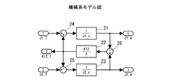
図3で示すオブザーバの機械系モデル20は、動力計の機械特性を伝達関数で表現したもので、2慣性機械系のモデルである。この実施例の機械系モデルは、J1.TとJ2.Tを入力として持ち、J1.w、K12.T、及びJ2.wを出力として持つ。
同図において、21はローラ慣性モーメント要素で、その出力はローラ角速度J1.wとして一般化プラントへ出力すると共に、減算手段26に出力する。22はばね剛性要素で、減算手段26により演算された動力計角速度とローラ角速度の差信号が入力されてシャフト捩れトルクK12.T信号として一般化プラントへ出力すると共に、加算手段24と減算手段25に出力する。加算手段24では、ローラ表面にかかる車両駆動力によるローラの回転モーメントJ1.Tとシャフト捩れトルクK12.Tが加算されてローラ慣性モーメント要素21に入力される。また、減算手段25では、入力された動力計トルク信号J2.Tとシャフト捩れトルクK12.Tの差信号が求められて動力計慣性モーメント要素23に出力され、この動力計慣性モーメント要素23において動力計角速度J2.wを演算して一般化プラントへ出力すると共に、減算手段26に出力される。
An observer
In the figure, 21 is a roller inertia moment element, and its output is outputted to the generalized plant as a roller angular velocity J1.w and also outputted to the subtracting means 26. A
図4は本発明に使用されるATR部103の一般化プラントモデルの例を示したものである。
図4で示すATR一般化プラントモデルは、その外乱としてローラ表面駆動力w11、インバータトルク制御誤差w12、軸トルク指令w13、ローラ角速度観測ノイズw14、軸トルク観測ノイズw15、及び動力計角速度観測ノイズw16が入力され、制御量としてz11〜z15が出力される。30はATRコントローラで、観測量c-in1、c-in2、及びc-in3が入力される。ATRコントローラ30では軸トルク制御のための状態方程式のパラメータを設定し、ゲインが小さくなるようアルゴリズムに基づいてパラメータを決定するための所定の演算を実行し、動力計のトルク指令c-outを生成する。ここで、c-in1はローラ角速度検出、 c-in2は軸トルク制御偏差、c-in3は動力計角速度検出である。また、一般化プラントモデルでは、制御量としてz11〜z15が生成される。
FIG. 4 shows an example of a generalized plant model of the
The ATR generalized plant model shown in FIG. 4 includes a roller surface driving force w11, an inverter torque control error w12, a shaft torque command w13, a roller angular velocity observation noise w14, a shaft torque observation noise w15, and a dynamometer angular velocity observation noise w16 as disturbances. Is input, and z11 to z15 are output as control amounts.
入力された外乱には、それぞれは重み係数付加手段31(Gw1(s))〜36(Gw6(s))、及び47(Gz1(s))〜51(Gz5(s))において各別に重み付けされ、求める特性が得られるようになっている。すなわち、手段31は車両駆動力に重み付けされ、ある定数、または、高域でゲインが高くなるような特性となってローラの回転モーメントトルクJ1.Tとし機械系モデル60(Gmec(s))に入力される。手段32では、インバータのトルク電流制御誤差に重み付けし、ある定数、または、高域でゲインが高くなるような特性にする。手段33では、軸トルク指令に重み付けし、ある定数、または、高域でゲインが高くなるような特性にされて減算部42に出力する。手段34では、ローラ角速度観測ノイズに重み付けし、ある定数、または、高域でゲインが高くなるような特性にする。手段35では、軸トルク観測ノイズに重み付けてある定数、または、高域でゲインが高くなるような特性とし、加算部41に出力する。手段36では、動力計角速度観測ノイズに重み付けし、ある定数、または、高域でゲインが高くなるような特性にして加算部45に出力する。
The input disturbances are respectively weighted individually by weighting coefficient adding means 31 (Gw1 (s)) to 36 (Gw6 (s)) and 47 (Gz1 (s)) to 51 (Gz5 (s)). The desired characteristics can be obtained. In other words, the
37はインバータ特性モデル部で、ATRコントローラ30の出力c-outに基づいてインバータの応答特性信号を生成し、手段32において重み付けされた信号と加算部43で加算され、動力計トルクJ2.Tとして機械系モデル60に入力される。
38は第1のエンコーダ特性モデルで、機械系モデル60で算出されたローラ角速度と、手段34においてローラ角速度観測ノイズw14に重み付けし、ある定数、または、高域でゲインが高くなるような特性にされたローラ角速度信号との和(加算部44で)が入力されてローラ角速度を検出する。この信号はローラ角速度検出c-in1の観測量としてATRコントローラ30に入力される。また、加算部44でのローラ角速度検出信号は手段51に出力されて重み付けされ、ある定数、または、高域でゲインが高くなるような特性にされて、重み付きローラ角速度信号z15にされる。
39は軸トルクを検出するトルクメータ特性モデルで、機械系モデル40からの軸トルクK12.Tと、手段35で重み付けされた軸トルク観測ノイズとの和信号(加算部41での)に基づいてトルクメータ特性信号を生成して減算部42に出力する。減算部42では手段33で重み付けされた軸トルク指令との差演算が実行され、その差信号が軸トルク制御偏差c-in2としてATRコントローラ30に出力すると共に、手段46にも出力される。手段46では入力された軸トルク制御偏差に積分特性を持つ重み関数を付加し、ある定数、または、高域でゲインが低くなるような特性にされて、重み付き軸トルク制御信号z13となる。また、加算部41で求められた軸トルク観測誤差信号は、手段48に入力されて重み付けされ、ある定数、または、高域でゲインが高くなるような特性にされて、重み付き軸トルク信号z12となる。
40は動力計角速度を検出する第2のエンコーダ特性モデルで、機械系モデル60からの動力計角速度J2.wと、手段36で重み付けされた動力計角速度観測誤差との和信号(加算部45にて)に基づいてエンコーダ特性信号を生成し、この信号は動力計角速度c-in3の観測量としてATRコントローラ30に入力される。また、加算部45での和信号は手段50で重み付けされ、ある定数、または、高域でゲインが高くなるような特性にされて、重み付き動力計角速度信号z14となる。
ATRコントローラ30では、入力された観測量c-in1, c-in2,及びc-in3に基づき軸トルク制御のための状態方程式のパラメータを設定し、ゲインが小さくなるようアルゴリズムに基づいてパラメータを決定するための所定の演算を実行し、演算された動力計トルク指令c-outを生成してインバータ特性モデル部37に出力すると共に、手段47に出力する。手段47ではインバータのトルク電流指令に重み付けをし、ある定数、または、高域でゲインが高くなるような特性にして重み付トルク電流指令信号z11として出力する。
なお、ATR一般化プラントモデルに使用される機械系モデルは、図3と同様に構成される。
The
The mechanical system model used for the ATR generalized plant model is configured in the same manner as in FIG.
また、図2、及び図4で示す一般化プラントモデルにおいて、入力される各観測ノイズは任意に選択される。例えば、動力計角速度観測ノイズが省かれるばあいには、この動力計角速度観測ノイズに重み付けする手段以降の関連する各主段、もしくは機能部分は除去される。 Moreover, in the generalized plant model shown in FIG. 2 and FIG. 4, each input observation noise is arbitrarily selected. For example, when the dynamometer angular velocity observation noise is omitted, the related main stages or functional parts after the means for weighting the dynamometer angular velocity observation noise are removed.
この実施例によれば、電気慣性制御回路を構成するオブザーバ部とATR部をH∞制御、・設計法と呼称されるコントローラ設計手法により設計し、機械系の共振特性、軸トルク検出特性、動力計角速度検出特性、ローラ角速度検出特性、及びインバータ応答特性を考慮した設計が可能となり、これら各特性の考慮されたトルク電流指令を得ることができる。したがって、共振特性が抑制され、より高応答で安定なシャシーダイナモメータシステムの電気慣性制御が可能となるものである。また、走行抵抗値を加算する場合や、設定慣性量を変更する場合でも、容易に対応が可能となるものである。 According to this embodiment, the observer part and the ATR part constituting the electric inertia control circuit are designed by a controller design technique called H∞ control, a design method, and resonance characteristics of the mechanical system, shaft torque detection characteristics, power Design that takes into account the angular velocity detection characteristics, roller angular speed detection characteristics, and inverter response characteristics is possible, and a torque current command that takes these characteristics into consideration can be obtained. Therefore, resonance characteristics are suppressed, and electric inertia control of a chassis dynamometer system with higher response and stability is possible. Further, even when the running resistance value is added or when the set inertia amount is changed, it is possible to easily cope with it.
図5は第2の実施例を示したもので、図1と異なる点は、ATR部103への入力は、軸トルク制御偏差SHT.eと動力計角速度検出w-dy.detとしたことである。
この実施例では、図1と比較して、ATR部103においてローラ角速度検出特性は考慮されてないが、軸トルク制御偏差SHT.eと動力計角速度検出w-y.detを使用することで略第1の実施例と同様の効果が得られるものである。
FIG. 5 shows the second embodiment. The difference from FIG. 1 is that the input to the
In this embodiment, the roller angular velocity detection characteristic is not considered in the
図6は第3の実施例を示したもので、図1と異なる点は、ATR部103への入力は、軸トルク制御偏差SHT.eとローラ角速度検出w-roller.detとしたことである。
この実施例では、図1と比較して、ATR部103において動力計角速度検出特性は考慮されてないが、軸トルク制御偏差SHT.eとローラ角速度検出wroller.detを使用することで略第1の実施例と同様の効果が得られるものである。
FIG. 6 shows the third embodiment. The difference from FIG. 1 is that the input to the
In this embodiment, dynamometer angular velocity detection characteristics are not considered in the
図7は第4の実施例を示したもので、図1と異なる点は、ATR部103への入力は、軸トルク制御偏差SHT.eのみとしたことである。
この実施例では、図1と比較して、ATR部103において軸トルク制御偏差SHT.eを使用することで略第1の実施例と同様の効果が得られるものである。
FIG. 7 shows the fourth embodiment. The difference from FIG. 1 is that the input to the
In this embodiment, the same effect as that of the first embodiment can be obtained by using the shaft torque control deviation SHT.e in the
図8は第5の実施例を示したもので、図1と異なる点は、オブザーバ101への入力は、軸トルク検出SHT.detとローラ角速度検出w-roller.detとしたことである。
この実施例では、図1と同様に、ATR部103において軸トルク制御偏差SHT.e、動力計角速度検出w-d y.det、及びローラ角速度検出w-roller.detを使用することで第1の実施例と同様の効果が得られるものである。
FIG. 8 shows the fifth embodiment. The difference from FIG. 1 is that the input to the
In this embodiment, similarly to FIG. 1, the
図9は第6の実施例を示したもので、図8と異なる点は、ATR部103への入力を、軸トルク制御偏差SHT.eと動力計角速度検出w-d y.detとしたことである。
この実施例では、図8と比較して、ATR部103においてローラ角速度検出特性は考慮されてないが、軸トルク制御偏差SHT.eと動力計角速度検出w-d y.detを使用することで略第5の実施例と同様の効果が得られるものである。
FIG. 9 shows the sixth embodiment. The difference from FIG. 8 is that the input to the
In this embodiment, compared with FIG. 8, the
図10は第7の実施例を示したもので、図8と異なる点は、ATR部103への入力は、軸トルク制御偏差SHT.eとローラ角速度検出w-roller.detとしたことである。
この実施例では、図8と比較して、ATR部103において動力計角速度検出特性は考慮されてないが、軸トルク制御偏差SHT.eとローラ角速度検w-roller.detを使用することで略第5の実施例と同様の効果が得られるものである。
FIG. 10 shows the seventh embodiment. The difference from FIG. 8 is that the input to the
In this embodiment, compared with FIG. 8, the dynamometer angular velocity detection characteristic is not considered in the
図11は第8の実施例を示したもので、図8と異なる点は、ATR部103への入力は、軸トルク制御偏差SHT.eのみとしたことである。
この実施例では、図8と比較して、ATR部103において軸トルク制御偏差SHT.eを使用することで略第5の実施例と同様の効果が得られるものである。
FIG. 11 shows the eighth embodiment. The difference from FIG. 8 is that the input to the
In this embodiment, the same effect as that of the fifth embodiment can be obtained by using the shaft torque control deviation SHT.e in the
図12は第9の実施例を示したもので、この実施例は、オブザーバ101の入力を軸トルク検出SHT.detと動力計角速度検出w-d y.detとし、ATR部103への入力は、慣性部102からの軸トルク制御指令SHT.refと、ローラ角速度検w-roller.det、動力計角速度検出w-d y.det、軸トルク検出SHT.detとしたもので、他は実施例1と同様の構成となっており、また、実施例1と同様の効果を得ることができる。
Figure 12 shows a ninth embodiment, this embodiment, the input of the
図13は第10の実施例を示したもので、図12と異なる点は、ATR部103への入力を、慣性部102からの軸トルク制御指令SHT.refと、動力計角速度検出w-d y.det、軸トルク検出SHT.detとしたことである。
この実施例では、ATR部103においてローラ角速度検出特性は考慮されてないが、軸トルク制御指令SHT.ref、動力計角速度検出w-d y.det、軸トルク検出SHT.detを使用することで略第9の実施例と同様の効果が得られるものである。
FIG. 13 shows the tenth embodiment. The difference from FIG. 12 is that the input to the
In this embodiment, the roller angular velocity detection characteristic is not considered in the
図14は第11の実施例を示したもので、図12と異なる点は、ATR部103への入力を、慣性部102からの軸トルク制御指令SHT.refと、ローラ角速度検w-roller.det、軸トルク検出SHT.detとしたことである。
この実施例では、ATR部103において動力計角速度検出特性は考慮されてないが、軸トルク制御指令SHT.ref、ローラ角速度検w-roller.det、軸トルク検出SHT.detを使用することで略第9の実施例と同様の効果が得られるものである。
FIG. 14 shows an eleventh embodiment. The difference from FIG. 12 is that the input to the
In this embodiment, the dynamometer angular velocity detection characteristics are not considered in the
図15は第12の実施例を示したもので、図12と異なる点は、ATR部103への入力を、慣性部102からの軸トルク制御指令SHT.refと、軸トルク検出SHT.detとしたことである。
この実施例では、ATR部103において軸トルク制御指令SHT.ref、軸トルク検出SHT.detを使用することで略第9の実施例と同様の効果が得られるものである。
FIG. 15 shows the twelfth embodiment, which is different from FIG. 12 in that the input to the
In this embodiment, by using the shaft torque control command SHT.ref and the shaft torque detection SHT.det in the
図16は第13の実施例を示したもので、この実施例は、オブザーバ101の入力を軸トルク検出SHT.detとローラ角速度検w-roller.detとし、ATR部103への入力を、慣性部102からの軸トルク制御指令SHT.refと、ローラ角速度検w-roller.det、動力計角速度検出w-d y.det、軸トルク検出SHT.detとしたもので、他は実施例9と略同様の構成となっており、また、実施例9と略同様の効果を得ることができる。
FIG. 16 shows a thirteenth embodiment. In this embodiment, the input of the
図17は第14の実施例を示したもので、この実施例は、オブザーバ101の入力を軸トルク検出SHT.detとローラ角速度検w-roller.detとし、ATR部103への入力を、慣性部102からの軸トルク制御指令SHT.refと、動力計角速度検出w-d y.det、軸トルク検出SHT.detとしたもので、他は実施例9と略同様の構成となっており、また、実施例9と略同様の効果を得ることができる。
FIG. 17 shows a fourteenth embodiment. In this embodiment, the input of the
図18は第15の実施例を示したもので、この実施例は、オブザーバ101の入力を軸トルク検出SHT.detとローラ角速度検w-roller.detとし、ATR部103への入力を、慣性部102からの軸トルク制御指令SHT.refと、ローラ角速度検w-roller.det、軸トルク検出SHT.detとしたもので、他は実施例9と略同様の構成となっており、また、実施例9と略同様の効果を得ることができる。
FIG. 18 shows a fifteenth embodiment. In this embodiment, the input of the
図19は第16の実施例を示したもので、この実施例は、オブザーバ101の入力を軸トルク検出SHT.detとローラ角速度検w-roller.detとし、ATR部103への入力を、慣性部102からの軸トルク制御指令SHT.refと、軸トルク検出SHT.detとしたもので、他は実施例9と略同様の構成となっており、また、実施例9と略同様の効果を得ることができる。
FIG. 19 shows a sixteenth embodiment. In this embodiment, the input of the
図20は本発明に使用されるオブザーバの他の例である。上記した各実施例に使用されるオブザーバは、図2で示すコントローラ設計手法により設計され一般化プラントモデルを用いることで説明してきたが、図20のように構成してローラ表面駆動力推定値を得るようにしてもよい。すなわち、動力計角速度検出値、若しくはローラ角速度検出値と軸トルク検出値から駆動力相当の信号を推定(ローラ表面駆動力推定)し、その推定値を減算部104に出力するように構成される。ここで、G(s)はローパスフィルタにおける相対次数1次以上の任意の伝達関数、Jrollerはローラの慣性モーメント、sは微分演算をラプラス演算子sにより表現したものである。
FIG. 20 shows another example of an observer used in the present invention. The observer used in each of the above-described embodiments has been described by using a generalized plant model designed by the controller design method shown in FIG. 2, but is configured as shown in FIG. You may make it obtain. That is, it is configured to estimate a dynamometer angular velocity detection value or a roller angular velocity detection value and a shaft torque detection value to estimate a driving force equivalent signal (roller surface driving force estimation) and output the estimated value to the
101… オブザーバ
102… 慣性部
103… ATR部
10… コントローラ
20,60… 機械系モデル
30… ATRコントローラ
Dy…動力計
IV…インバータ
RP…電気慣性制御回路
R…ローラ
EC(EC1,EC2)…エンコーダ
TM…トルクメータ
DESCRIPTION OF
Claims (4)
前記オブザーバ部は軸トルク検出値、角速度検出値を入力してローラ表面駆動力推定値を算出し、
前記ATR部をATR一般化プラントモデルに基づき、H∞制御、μ設計法と呼称されるコントローラ設計手法により設計し、このATR部には、前記慣性部が前記ローラ表面駆動力推定値に応じて設定した慣性量の演算値を入力すると共に、動力計角速度検出値、ローラ角速度検出値、及び軸トルク検出値の何れかの検出値をATR部に入力してトルク電流指令を生成することを特徴とした電気慣性制御装置。 A roller and a dynamometer are connected via a shaft, and a torque current command is calculated by inputting a dynamometer rotation signal, a shaft torque signal, and a roller rotation signal into an electric inertia control circuit having an observer unit, an ATR unit, and an inertia unit. In the case where the electric inertia control is performed via the inverter according to the obtained torque current command,
The observer unit inputs a shaft torque detection value and an angular velocity detection value to calculate a roller surface driving force estimation value,
The ATR part is designed by a controller design method called H∞ control and μ design method based on the ATR generalized plant model. In this ATR part, the inertia part depends on the estimated roller surface driving force. A calculation value of the set inertia amount is input, and a detection value of any one of a dynamometer angular velocity detection value, a roller angular velocity detection value, and a shaft torque detection value is input to the ATR unit to generate a torque current command. Electric inertia control device.
Priority Applications (1)
| Application Number | Priority Date | Filing Date | Title |
|---|---|---|---|
| JP2008181010A JP5200714B2 (en) | 2008-07-11 | 2008-07-11 | Electric inertia control device |
Applications Claiming Priority (1)
| Application Number | Priority Date | Filing Date | Title |
|---|---|---|---|
| JP2008181010A JP5200714B2 (en) | 2008-07-11 | 2008-07-11 | Electric inertia control device |
Publications (2)
| Publication Number | Publication Date |
|---|---|
| JP2010019712A JP2010019712A (en) | 2010-01-28 |
| JP5200714B2 true JP5200714B2 (en) | 2013-06-05 |
Family
ID=41704770
Family Applications (1)
| Application Number | Title | Priority Date | Filing Date |
|---|---|---|---|
| JP2008181010A Active JP5200714B2 (en) | 2008-07-11 | 2008-07-11 | Electric inertia control device |
Country Status (1)
| Country | Link |
|---|---|
| JP (1) | JP5200714B2 (en) |
Cited By (1)
| Publication number | Priority date | Publication date | Assignee | Title |
|---|---|---|---|---|
| JP7128754B2 (en) | 2019-01-30 | 2022-08-31 | ケイミュー株式会社 | Construction material manufacturing method |
Family Cites Families (18)
| Publication number | Priority date | Publication date | Assignee | Title |
|---|---|---|---|---|
| JP2884698B2 (en) * | 1990-04-27 | 1999-04-19 | 株式会社明電舎 | Inertial simulator |
| JP2841902B2 (en) * | 1991-02-28 | 1998-12-24 | 富士電機株式会社 | Control device for dynamic simulator |
| JP3158461B2 (en) * | 1991-03-07 | 2001-04-23 | 株式会社明電舎 | Dynamometer electric inertia compensation method |
| JP2647576B2 (en) * | 1991-06-28 | 1997-08-27 | 株式会社日立製作所 | Electric inertia compensation controller for driving test machine |
| JP2568008B2 (en) * | 1991-07-19 | 1996-12-25 | 株式会社日立製作所 | Electric inertia control device for power transmission system tester |
| JP3489241B2 (en) * | 1995-02-13 | 2004-01-19 | 株式会社明電舎 | Automotive engine test equipment |
| JPH10239219A (en) * | 1997-02-27 | 1998-09-11 | Meidensha Corp | Engine spindle torque control device |
| JP3687305B2 (en) * | 1997-09-30 | 2005-08-24 | 株式会社明電舎 | Dynamometer system |
| JP3405924B2 (en) * | 1998-07-21 | 2003-05-12 | トヨタ自動車株式会社 | Load transmission device |
| JP3772721B2 (en) * | 2001-10-11 | 2006-05-10 | 株式会社明電舎 | Engine bench system and method for measuring engine characteristics |
| JP3775284B2 (en) * | 2001-11-08 | 2006-05-17 | 株式会社明電舎 | Engine bench system and method for measuring engine characteristics |
| JP4019709B2 (en) * | 2002-01-09 | 2007-12-12 | 株式会社明電舎 | Engine bench system |
| JP4061908B2 (en) * | 2002-01-18 | 2008-03-19 | 株式会社明電舎 | Vehicle speed control device |
| JP4321124B2 (en) * | 2003-06-05 | 2009-08-26 | 株式会社明電舎 | Electric inertia control system for power measurement system |
| JP4655677B2 (en) * | 2005-02-28 | 2011-03-23 | シンフォニアテクノロジー株式会社 | Power transmission system test apparatus and control method thereof |
| JP4699848B2 (en) * | 2005-09-27 | 2011-06-15 | 株式会社明電舎 | Chassis dynamometer |
| JP4784451B2 (en) * | 2006-09-12 | 2011-10-05 | 株式会社明電舎 | Control method and apparatus for engine bench system |
| JP4835508B2 (en) * | 2007-05-17 | 2011-12-14 | 株式会社明電舎 | Electric inertia control method |
-
2008
- 2008-07-11 JP JP2008181010A patent/JP5200714B2/en active Active
Cited By (1)
| Publication number | Priority date | Publication date | Assignee | Title |
|---|---|---|---|---|
| JP7128754B2 (en) | 2019-01-30 | 2022-08-31 | ケイミュー株式会社 | Construction material manufacturing method |
Also Published As
| Publication number | Publication date |
|---|---|
| JP2010019712A (en) | 2010-01-28 |
Similar Documents
| Publication | Publication Date | Title |
|---|---|---|
| JP4835508B2 (en) | Electric inertia control method | |
| JP5200715B2 (en) | Electric inertia control device of dynamometer system | |
| JP4685509B2 (en) | AC motor drive control device and drive control method | |
| JP5146102B2 (en) | Vehicle behavior test equipment | |
| JP4766039B2 (en) | Control method of engine bench system | |
| JP4784451B2 (en) | Control method and apparatus for engine bench system | |
| JP4862752B2 (en) | Electric inertia control method | |
| JP5262036B2 (en) | Control method of chassis dynamometer system | |
| JP4645231B2 (en) | Power transmission system test apparatus and control method thereof | |
| JP2011257205A (en) | Axial torque controller for dynamometer system | |
| JP5644409B2 (en) | Electric motor position control device | |
| JP6042124B2 (en) | 2-inertia speed controller | |
| JP4914979B2 (en) | Motor control device and motor control method | |
| JP5234774B2 (en) | Chassis dynamo controller | |
| JP4591177B2 (en) | Engine test equipment | |
| JP2011160574A (en) | Speed control device for motor | |
| JP5200714B2 (en) | Electric inertia control device | |
| JP2013015386A (en) | Engine bench system control method | |
| JP5223477B2 (en) | Driving force control method and apparatus for dynamometer system | |
| JP5605128B2 (en) | Dynamometer shaft torque control device | |
| JP5292922B2 (en) | Method and apparatus for estimating roller surface driving force | |
| JP5200697B2 (en) | Speed controller for chassis dynamometer | |
| JP3856215B2 (en) | Speed control device | |
| JP2010043940A (en) | Apparatus for testing power transmission system and its control method | |
| JP5200713B2 (en) | Speed control method and apparatus for power measurement system |
Legal Events
| Date | Code | Title | Description |
|---|---|---|---|
| A621 | Written request for application examination |
Free format text: JAPANESE INTERMEDIATE CODE: A621 Effective date: 20110510 |
|
| TRDD | Decision of grant or rejection written | ||
| A01 | Written decision to grant a patent or to grant a registration (utility model) |
Free format text: JAPANESE INTERMEDIATE CODE: A01 Effective date: 20130115 |
|
| A61 | First payment of annual fees (during grant procedure) |
Free format text: JAPANESE INTERMEDIATE CODE: A61 Effective date: 20130128 |
|
| R150 | Certificate of patent or registration of utility model |
Ref document number: 5200714 Country of ref document: JP Free format text: JAPANESE INTERMEDIATE CODE: R150 Free format text: JAPANESE INTERMEDIATE CODE: R150 |
|
| FPAY | Renewal fee payment (event date is renewal date of database) |
Free format text: PAYMENT UNTIL: 20160222 Year of fee payment: 3 |