JP4061908B2 - Vehicle speed control device - Google Patents
Vehicle speed control device Download PDFInfo
- Publication number
- JP4061908B2 JP4061908B2 JP2002009525A JP2002009525A JP4061908B2 JP 4061908 B2 JP4061908 B2 JP 4061908B2 JP 2002009525 A JP2002009525 A JP 2002009525A JP 2002009525 A JP2002009525 A JP 2002009525A JP 4061908 B2 JP4061908 B2 JP 4061908B2
- Authority
- JP
- Japan
- Prior art keywords
- vehicle speed
- vehicle
- control circuit
- command
- driving force
- Prior art date
- Legal status (The legal status is an assumption and is not a legal conclusion. Google has not performed a legal analysis and makes no representation as to the accuracy of the status listed.)
- Expired - Fee Related
Links
- 230000001133 acceleration Effects 0.000 description 20
- 238000001514 detection method Methods 0.000 description 4
- 238000010586 diagram Methods 0.000 description 4
- 238000000034 method Methods 0.000 description 3
- 238000009825 accumulation Methods 0.000 description 1
- 230000005540 biological transmission Effects 0.000 description 1
- 239000000498 cooling water Substances 0.000 description 1
- 230000004069 differentiation Effects 0.000 description 1
- 230000010354 integration Effects 0.000 description 1
Images


Landscapes
- Feedback Control In General (AREA)
- Controls For Constant Speed Travelling (AREA)
Description
【0001】
【発明の属する技術分野】
この発明は、シャシーダイナモメータ等の車両試験装置上で車両を運転するときの車両速度制御装置に関する。
【0002】
【従来の技術】
従来、シャシーダイナモメータ上で車両を運転するときの速度制御方法には、図2に示すような加速度マイナ付速度制御方式がある(特公昭61−18433号)。この方式においては、車速指令信号VSと車両4の車速検出信号Vとの偏差信号を速度制御器1で比例演算して加減速度指令信号を得、また車速検出信号Vを微分演算器5で演算して加減速度検出信号を得、この両加速度信号の偏差を加減速度演算器2に入力して比例積分演算してアクセルペダルストローク信号θSとし、さらにストローク制御器3によりアクセルペダルストローク制御信号θとし、アクセルペダルを操作して車両4の車速Vを車速指令VSと一致するように制御している。なお、構成要素のブロック内の記号は、各構成要素の伝達関数を示す。
【0003】
上記した従来の加速度マイナ付速度制御装置は、フィードバック制御であるので、速度制御器1等のゲイン調整を行う必要があり、また車両4の伝達関数MG(S)は多数の変化要素があり、これらの変化要素が変化する毎にやはり速度制御器1等のゲイン調整が必要となった。さらに、フィードバック制御ループは閉ループ伝達関数として表わされ、速度制御器1等のゲインによって決まる制御応答の遅れが存在する。
【0004】
これらの点を改善するため、本出願人は車両の伝達関数の逆関数MG-1(S)を用いたフィードフォワード制御方式を提案した(特願平6−75532号)。この制御方法は、車両の伝達関数MG(S)の逆関数MG(S)-1を用いて車速指令VSに車速Vを一致させるために必要なアクセルペダルストロークQAを直接演算により算出し、このQAをアクセルアクチュエータ操作信号QSとして出力する。これによりアクセルアクチュエータは作動し、アクセルアクチュエータストロークθを得てθ=θAとし、車両のアクセルペダルを動かし、車速指令VSに車速Vを一致させるものである。
【0005】
しかしながら、車両の伝達関数の逆関数を用いたフィードフォワード制御は、フィードバック制御の欠点を理論上除去できるものではあるが、実際には車両の伝達関数の逆関数には必ず誤差が生じ、車速指令と車速との間に誤差が生じた。
【0006】
そこで、本出願人はこの誤差を解消するために図3に示す速度制御装置を提案した(特開平7−325019号)。Aは加算器A3部分を除いて、前述したフィードフォワード制御回路であり、6は逆関数MG(S)-1を有する逆関数回路である。Bは車速指令VSと車速Vに偏差が生じたときに逆関数回路6からのアクセルペダルストローク指令を補正するアクセルペダルストローク補正指令を出力する車両モデル補償制御回路である。
【0007】
補償制御回路Bにおいて、7は制御回路Aと同じ伝達関数を有する車両制御モデル伝達関数回路、8は回路7からの車速指令VS′を微分するD演算器、A1は回路7からの車速指令VS′と車速Vの偏差を検出する加算器、9はこの偏差に比例した信号を出力するP演算器、10は車速Vを微分するD演算器、A2は演算器8〜10の出力を加算する加算器、11は加算器A2からの信号を比例積分し、加算器A3にアクセルペダルストローク補正指令θCを出力するPI演算器である。
【0008】
車速指令VSで車両4を加速した時、指令に対する車速の遅れ分を補償するアクセルペダルのストローク指令がPI演算器11の積分項に蓄積され、車速指令VSが加速から定常に移った時この積分項に蓄積された値をPIの時定数で放出する間、余分なアクセル指令を出すことになり、車速のオーバーシュートが発生する。回路7はこの車速の遅れ分による積分項への蓄積を防ぎ、車速のオーバーシュートを防止する。
【0009】
演算器8〜11からなるフィードバック回路は、加速度指令フォーシングを持つ加速度マイナ付速度制御回路となっていて、D演算器8からの加減速度指令とP演算器9からの車速偏差信号との合計を新たな加減速指令とし、D演算器10からの加減速検出信号との偏差信号を加算器A2から出力させ、PI演算器11からの補正指令θCを加算器A3に入力し、ストローク指令θAをθSに補正する。この結果、車両の伝達関数の逆関数MG(S)-1に誤差があった場合、その誤差分のアクセルストローク指令のみPI演算器11に蓄積され、補償される。又、D演算器8,10の相殺効果により速度指令VS′と車速Vの偏差が相殺され、オーバーシュートが防止される。
【0010】
【発明が解決しようとする課題】
しかしながら、図3に示した従来装置は、フィードフォワード制御による誤差分を補償するフィードバック制御回路の構成が複雑であり、比例、微分、積分の各演算が行われるためにそのゲイン調整も容易でなかった。又、車両4においては、実際にはダイナモメータ等による走行抵抗があり、この走行抵抗分が車両4の駆動力にフィードバックされているので、その後の積分項がキャンセルされ、制御誤差を生じ、この制御誤差を補償するために、フィードバック制御回路の構成が複雑となった。
【0011】
この発明は上記のような課題を解決するために成されたものであり、フィードフォワード制御回路の誤差分を補償するフィードバック制御回路の構成を簡単にするとともに、そのゲイン調整を簡単にすることができる車両速度制御装置を得ることを目的とする。
【0012】
【課題を解決するための手段】
この発明による車両速度制御装置は、車両試験装置上で車両を運転するときの車両速度制御装置において、車両の伝達関数の逆関数をフィードフォワードの伝達関数に用いて車速指令から直接アクセル開度を演算出力し、そのアクセル操作により車速を車速指令に一致させるフィードフォワード制御回路と、車速指令と車速との偏差を比例演算する比例演算部の出力と車両試験装置上での車速に応じた車両の走行抵抗を加算し、この加算値により前記フィードフォワード制御回路の車両の駆動力を補償して前記フィードフォワード制御回路の誤差分を補償するフィードバック制御回路と、前記フィードバック制御回路による補償後の駆動力をフィードバック制御する駆動力オブザーバ補正回路を備えたものである。
【0013】
【発明の実施の形態】
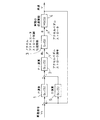
以下、この発明の実施の形態を図面とともに説明する。図1はこの実施形態による車両速度制御装置のブロック図を示す。図において、12は車速指令VSを入力され、加速力Fαを演算する加速力演算部、13は車速指令V S と車速Vとの偏差を比例演算する比例演算部、14は車速Vを入力され、走行抵抗FRLを設定する走行抵抗設定器、15は各演算部12,13及び走行抵抗設定器14の各出力を加算して駆動力FRを出力する加算器、16は機械慣性の慣性モーメントJO(車重Wに対応)と検出加速度を乗算して機械慣性FM=WdV/dtを得る乗算器、17は機械慣性FMと、走行抵抗FRLと電気慣性FEを加算したものに対応する検出ダイナモメータトルクを入力され、検出駆動力を出力する加算器である。
【0014】
又、加算器18には駆動力FRと一次遅れ要素19の出力が入力され、その偏差が駆動力指令として出力される。この駆動力指令と加算器17からの検出駆動力が加算器20に入力され、その偏差は切換スイッチ21を介して一次遅れ要素19に入力される。加算器18からの駆動力指令は乗算器22でタイヤ半径rが乗算されてアクスル軸トルクτ a が算出され、アクスル軸トルクτ a は除算器23に入力され、トランスミッション比iMとデフ比iDとを乗算したものにより除算されてエンジン出力トルクτ e が算出される。
【0015】
24は収録エンジン特性部であり、エンジン出力トルクτ e 、エンジン回転数Ne、車速指令変化率、冷却水温、吸気温度、大気圧などを入力され、シーマック学習機能によりこれらの各変化要素間の荷重テーブルを作成して記憶する。そして、入力された各変化要素に応じてアクセルアクチュエータ操作信号θSを荷重テーブルから読み出し、出力する。開度制御部25は操作信号θSを入力されてアクセル開度θを出力する。
【0016】
アクセル開度θは車両4に入力される。車両4においては、まずエンジン特性部26があり、入力されたアクセル開度θ及びエンジン回転数Neに応じたエンジン出力トルクτ e が出力される。出力トルクτ e は乗算器27に入力され、iM×iDを乗算されてアクセル軸トルクτ a が演算され、この軸トルクτ a は除算器28に入力され、タイヤ半径rで除算して駆動力FRを算出し、加算器29では駆動力FRからダイナモメータ等による実際の走行抵抗分30が減算され、加速力Fαが得られる。加速力Fαは除算器31に入力され、車重Wで除算されて加速度αが算出され、加速度αは積分器32に入力されて車速Vが得られる。
【0017】
上記構成において、加速力演算部12、乗算器22、除算器23、収録エンジン特性部24により車両4の伝達関数MG(S)の逆関数MG(S)-1を有する逆関数回路を形成し、この逆関数回路に開度制御部25及び車両4を加えてフィードフォワード制御回路を形成する。このフィードフォワード制御回路の誤差分を補償するフィードバック回路としては、従来のような複雑な回路構成とせず、基本的には比例演算部13のみである。これは、車両4において、実際には走行抵抗30が存在するために積分項がキャンセルされるために、その補償が必要となるが、走行抵抗設定器14からの走行抵抗をフィードバック系に加算することにより車両4における走行抵抗30が相殺されるため、補償の必要がなくなるためである。従って、フィードバック制御回路は基本的には比例演算器13のみで構成され、構成簡単でゲイン調整も容易となる。ただし、フィードバック系に走行抵抗分を加算したことによる誤差も生じる。このため、構成要素16〜20による駆動力オブザーバ補正回路を設け、車両の駆動力をフィードバック制御するようにした。
【0018】
なお、変速中に駆動力オブザーバ補正回路が作動すると、却って誤差が生じるので、切換スイッチ21を設け、変速中は駆動力オブザーバ補正回路が作動しないようにした。
【0019】
【発明の効果】
以上のようにこの発明によれば、走行抵抗設定器からの走行抵抗をフィードバック系に加算したので、車両における走行抵抗分が相殺され、フィードフォワード制御による誤差分を補償するフィードバック制御回路の構成を基本的には比例演算器のみとすることができ、構成簡単でゲイン調整も簡単にすることができる。
【図面の簡単な説明】
【図1】 この発明による車両速度制御装置のブロック図である。
【図2】 従来装置のブロック図である。
【図3】 他の従来装置のブロック図である。
【符号の説明】
4…車両
13…比例演算部
14…走行抵抗設定器[0001]
BACKGROUND OF THE INVENTION
The present invention relates to a vehicle speed control device for driving a vehicle on a vehicle test device such as a chassis dynamometer.
[0002]
[Prior art]
Conventionally, as a speed control method for driving a vehicle on a chassis dynamometer, there is a speed control system with an acceleration minor as shown in FIG. 2 (Japanese Patent Publication No. 61-18433). In this system, a deviation signal between the vehicle speed command signal V S and the vehicle speed detection signal V of the vehicle 4 is proportionally calculated by the
[0003]
Since the above-described conventional speed control device with an acceleration minor is feedback control, it is necessary to adjust the gain of the
[0004]
In order to improve these points, the present applicant has proposed a feedforward control method using an inverse function MG −1 (S) of a vehicle transfer function (Japanese Patent Application No. 6-75532). In this control method, the accelerator pedal stroke Q A necessary for making the vehicle speed V coincide with the vehicle speed command V S is calculated by direct calculation using the inverse function MG (S) −1 of the vehicle transfer function MG (S). , Q A is output as an accelerator actuator operation signal Q S. As a result, the accelerator actuator is actuated to obtain the accelerator actuator stroke θ, θ = θ A , the accelerator pedal of the vehicle is moved, and the vehicle speed V is matched with the vehicle speed command V S.
[0005]
However, feed-forward control using the inverse function of the vehicle transfer function can theoretically eliminate the drawbacks of feedback control, but in reality, an error always occurs in the inverse function of the vehicle transfer function, and the vehicle speed command There was an error between the vehicle speed and the vehicle speed.
[0006]
Therefore, the present applicant has proposed a speed control device shown in FIG. 3 in order to eliminate this error (Japanese Patent Laid-Open No. 7-325019). A is the above-described feedforward control circuit except for the adder A 3 portion, and 6 is an inverse function circuit having an inverse function MG (S) −1 . B is a vehicle model compensation control circuit that outputs an accelerator pedal stroke correction command for correcting the accelerator pedal stroke command from the inverse function circuit 6 when a deviation occurs between the vehicle speed command V S and the vehicle speed V.
[0007]
In the compensation control circuit B, 7 is a vehicle control model transfer function circuit having the same transfer function as that of the control circuit A, 8 is a D calculator for differentiating the vehicle speed command V S 'from the circuit 7, and A 1 is a vehicle speed from the circuit 7. An adder that detects a deviation between the command V S 'and the vehicle speed V, 9 is a P calculator that outputs a signal proportional to the deviation, 10 is a D calculator that differentiates the vehicle speed V, and A 2 is a calculator 8-10. An adder 11 for adding the outputs is a PI calculator that proportionally integrates the signal from the adder A 2 and outputs an accelerator pedal stroke correction command θ C to the adder A 3 .
[0008]
When the vehicle 4 is accelerated by the vehicle speed command V S , an accelerator pedal stroke command that compensates for a delay in the vehicle speed with respect to the command is accumulated in the integral term of the PI calculator 11, and the vehicle speed command V S shifts from acceleration to steady state. While the value accumulated in the integral term is released with the PI time constant, an extra accelerator command is issued, and an overshoot of the vehicle speed occurs. The circuit 7 prevents accumulation in the integral term due to the delay of the vehicle speed, and prevents overshoot of the vehicle speed.
[0009]
The feedback circuit composed of the calculators 8 to 11 is a speed control circuit with an acceleration minor having acceleration command forcing, and is the sum of the acceleration / deceleration command from the D calculator 8 and the vehicle speed deviation signal from the P calculator 9. Is a new acceleration / deceleration command, a deviation signal from the acceleration / deceleration detection signal from the D calculator 10 is output from the adder A 2, and a correction command θ C from the PI calculator 11 is input to the adder A 3 , Stroke command θ A is corrected to θ S. As a result, if there is an error in the inverse function MG (S) −1 of the vehicle transfer function, only the accelerator stroke command corresponding to the error is accumulated in the PI calculator 11 and compensated. Further, the deviation between the speed command V S 'and the vehicle speed V is canceled by the canceling effect of the D calculators 8 and 10, and overshoot is prevented.
[0010]
[Problems to be solved by the invention]
However, the conventional apparatus shown in FIG. 3 has a complicated configuration of the feedback control circuit that compensates for the error due to the feedforward control, and proportional adjustment, differentiation, and integration are performed, so that gain adjustment is not easy. It was. Further, in the vehicle 4, there is actually a running resistance by a dynamometer or the like, and since this running resistance is fed back to the driving force of the vehicle 4, the subsequent integral term is canceled and a control error is generated. In order to compensate for the control error, the configuration of the feedback control circuit has become complicated.
[0011]
The present invention has been made to solve the above-described problems, and it is possible to simplify the configuration of the feedback control circuit that compensates for the error of the feedforward control circuit and to simplify the gain adjustment. It is an object of the present invention to obtain a vehicle speed control device that can be used.
[0012]
[Means for Solving the Problems]
The vehicle speed control device according to the present invention is a vehicle speed control device for driving a vehicle on a vehicle test device, and uses the inverse function of the vehicle transfer function as the feedforward transfer function to directly determine the accelerator opening from the vehicle speed command. A feed-forward control circuit that outputs the calculation and makes the vehicle speed coincide with the vehicle speed command by operating the accelerator, the output of the proportional calculation unit that proportionally calculates the deviation between the vehicle speed command and the vehicle speed, and the vehicle according to the vehicle speed on the vehicle test device A feedback control circuit that adds a running resistance, compensates the vehicle driving force of the feedforward control circuit by the added value to compensate for an error in the feedforward control circuit, and a driving force after compensation by the feedback control circuit Is provided with a driving force observer correction circuit for feedback control .
[0013]
DETAILED DESCRIPTION OF THE INVENTION
Embodiments of the present invention will be described below with reference to the drawings. FIG. 1 shows a block diagram of a vehicle speed control apparatus according to this embodiment. In the figure, 12 is an input of a vehicle speed command V S and an acceleration force calculation unit for calculating an acceleration force F α , 13 is a proportional calculation unit for proportionally calculating a deviation between the vehicle speed command V S and the vehicle speed V, and 14 is a vehicle speed V. is input, the running resistance setting unit that sets a
[0014]
The output of the driving force F R and the
[0015]
[0016]
The accelerator opening θ is input to the vehicle 4. In a vehicle 4, first there is an
[0017]
In the above configuration, the acceleration
[0018]
If the driving force observer correction circuit is activated during a shift, an error occurs. Therefore, a
[0019]
【The invention's effect】
As described above, according to the present invention, since the running resistance from the running resistance setting device is added to the feedback system, the running resistance in the vehicle is canceled out, and the configuration of the feedback control circuit that compensates for the error due to feedforward control is provided. Basically, only a proportional calculator can be used, and the configuration is simple and the gain adjustment can be simplified.
[Brief description of the drawings]
FIG. 1 is a block diagram of a vehicle speed control device according to the present invention.
FIG. 2 is a block diagram of a conventional apparatus.
FIG. 3 is a block diagram of another conventional apparatus.
[Explanation of symbols]
4 ...
Claims (1)
Priority Applications (1)
| Application Number | Priority Date | Filing Date | Title |
|---|---|---|---|
| JP2002009525A JP4061908B2 (en) | 2002-01-18 | 2002-01-18 | Vehicle speed control device |
Applications Claiming Priority (1)
| Application Number | Priority Date | Filing Date | Title |
|---|---|---|---|
| JP2002009525A JP4061908B2 (en) | 2002-01-18 | 2002-01-18 | Vehicle speed control device |
Publications (2)
| Publication Number | Publication Date |
|---|---|
| JP2003214990A JP2003214990A (en) | 2003-07-30 |
| JP4061908B2 true JP4061908B2 (en) | 2008-03-19 |
Family
ID=27647516
Family Applications (1)
| Application Number | Title | Priority Date | Filing Date |
|---|---|---|---|
| JP2002009525A Expired - Fee Related JP4061908B2 (en) | 2002-01-18 | 2002-01-18 | Vehicle speed control device |
Country Status (1)
| Country | Link |
|---|---|
| JP (1) | JP4061908B2 (en) |
Families Citing this family (8)
| Publication number | Priority date | Publication date | Assignee | Title |
|---|---|---|---|---|
| JP4349187B2 (en) | 2004-04-15 | 2009-10-21 | 株式会社明電舎 | Vehicle speed control device |
| JP4606246B2 (en) * | 2005-05-16 | 2011-01-05 | 株式会社小野測器 | Chassis dynamometer |
| JP5245307B2 (en) * | 2007-07-18 | 2013-07-24 | 株式会社明電舎 | Driving force characteristics recording method in vehicle speed control |
| JP5256671B2 (en) * | 2007-09-12 | 2013-08-07 | 株式会社明電舎 | Driving speed characteristics recording method for vehicle speed control |
| JP5200714B2 (en) * | 2008-07-11 | 2013-06-05 | 株式会社明電舎 | Electric inertia control device |
| JP5304485B2 (en) * | 2009-06-30 | 2013-10-02 | ヤマハ株式会社 | Accelerator opening estimation device and engine sound generation device |
| WO2013144974A2 (en) * | 2012-03-29 | 2013-10-03 | Tvs Motor Company Limited | A method of predicting throttle position based on engine speed signal and a vehicle using the same |
| CN115315621B (en) * | 2020-04-10 | 2025-11-18 | 株式会社堀场制作所 | Automatic driving device for test subject, automatic driving method for test subject, and test system for test subject |
-
2002
- 2002-01-18 JP JP2002009525A patent/JP4061908B2/en not_active Expired - Fee Related
Also Published As
| Publication number | Publication date |
|---|---|
| JP2003214990A (en) | 2003-07-30 |
Similar Documents
| Publication | Publication Date | Title |
|---|---|---|
| JP4349187B2 (en) | Vehicle speed control device | |
| US8364368B2 (en) | Acceleration control apparatus for vehicle | |
| US5270628A (en) | Method and apparatus for automatic robotic control of a vehicle | |
| JP2551420B2 (en) | Clutch control device | |
| JP5098736B2 (en) | Vehicle speed control device | |
| JP4061908B2 (en) | Vehicle speed control device | |
| JP3873584B2 (en) | Automatic driving device for vehicles | |
| US11745743B2 (en) | Method for operating a motor vehicle, control device, and motor vehicle | |
| JPH0439608B2 (en) | ||
| JPH052179B2 (en) | ||
| JPH0666682A (en) | Control method for brake dynamo system | |
| JPH1114505A (en) | Controller for running resistance of chassis dynamometer | |
| JP4521743B2 (en) | Method and apparatus for calculating external values, in particular moments, for driving or braking a vehicle | |
| JP3503187B2 (en) | Vehicle speed control device | |
| JP3687305B2 (en) | Dynamometer system | |
| JP2001073817A (en) | Throttle control device | |
| JP3608388B2 (en) | Travel resistance estimation device and vehicle travel control device | |
| JP3677104B2 (en) | Composite test apparatus and electric inertia control method thereof | |
| JP2647576B2 (en) | Electric inertia compensation controller for driving test machine | |
| JPH04314630A (en) | Constant speed running device for vehicle | |
| JP3277740B2 (en) | Automatic speed control device for vehicles | |
| JP3988468B2 (en) | Cold speed correction method and correction device for vehicle speed control device | |
| JP2005343422A (en) | Driving force control device | |
| JP5672869B2 (en) | Vehicle system vibration control device | |
| JP3596318B2 (en) | Control device for vehicle with continuously variable transmission |
Legal Events
| Date | Code | Title | Description |
|---|---|---|---|
| A621 | Written request for application examination |
Free format text: JAPANESE INTERMEDIATE CODE: A621 Effective date: 20041208 |
|
| A977 | Report on retrieval |
Free format text: JAPANESE INTERMEDIATE CODE: A971007 Effective date: 20060112 |
|
| A131 | Notification of reasons for refusal |
Free format text: JAPANESE INTERMEDIATE CODE: A131 Effective date: 20070911 |
|
| A521 | Request for written amendment filed |
Free format text: JAPANESE INTERMEDIATE CODE: A523 Effective date: 20071107 |
|
| TRDD | Decision of grant or rejection written | ||
| A01 | Written decision to grant a patent or to grant a registration (utility model) |
Free format text: JAPANESE INTERMEDIATE CODE: A01 Effective date: 20071204 |
|
| A61 | First payment of annual fees (during grant procedure) |
Free format text: JAPANESE INTERMEDIATE CODE: A61 Effective date: 20071217 |
|
| R150 | Certificate of patent or registration of utility model |
Free format text: JAPANESE INTERMEDIATE CODE: R150 Ref document number: 4061908 Country of ref document: JP Free format text: JAPANESE INTERMEDIATE CODE: R150 |
|
| FPAY | Renewal fee payment (event date is renewal date of database) |
Free format text: PAYMENT UNTIL: 20110111 Year of fee payment: 3 |
|
| FPAY | Renewal fee payment (event date is renewal date of database) |
Free format text: PAYMENT UNTIL: 20120111 Year of fee payment: 4 |
|
| FPAY | Renewal fee payment (event date is renewal date of database) |
Free format text: PAYMENT UNTIL: 20130111 Year of fee payment: 5 |
|
| FPAY | Renewal fee payment (event date is renewal date of database) |
Free format text: PAYMENT UNTIL: 20140111 Year of fee payment: 6 |
|
| LAPS | Cancellation because of no payment of annual fees |