WO2015053155A1 - 供給流路遮断装置および供給流路遮断制御方法 - Google Patents
供給流路遮断装置および供給流路遮断制御方法 Download PDFInfo
- Publication number
- WO2015053155A1 WO2015053155A1 PCT/JP2014/076327 JP2014076327W WO2015053155A1 WO 2015053155 A1 WO2015053155 A1 WO 2015053155A1 JP 2014076327 W JP2014076327 W JP 2014076327W WO 2015053155 A1 WO2015053155 A1 WO 2015053155A1
- Authority
- WO
- WIPO (PCT)
- Prior art keywords
- ink
- flow path
- inkjet head
- pressure
- supply flow
- Prior art date
- Legal status (The legal status is an assumption and is not a legal conclusion. Google has not performed a legal analysis and makes no representation as to the accuracy of the status listed.)
- Ceased
Links
Images


Classifications
-
- B—PERFORMING OPERATIONS; TRANSPORTING
- B41—PRINTING; LINING MACHINES; TYPEWRITERS; STAMPS
- B41J—TYPEWRITERS; SELECTIVE PRINTING MECHANISMS, i.e. MECHANISMS PRINTING OTHERWISE THAN FROM A FORME; CORRECTION OF TYPOGRAPHICAL ERRORS
- B41J2/00—Typewriters or selective printing mechanisms characterised by the printing or marking process for which they are designed
- B41J2/005—Typewriters or selective printing mechanisms characterised by the printing or marking process for which they are designed characterised by bringing liquid or particles selectively into contact with a printing material
- B41J2/01—Ink jet
- B41J2/17—Ink jet characterised by ink handling
- B41J2/175—Ink supply systems ; Circuit parts therefor
Definitions
- the present invention relates to an inkjet head that reciprocates and a mechanism that blocks an ink supply channel during acceleration / deceleration of the reciprocating movement of the inkjet head.
- the present invention relates to a supply flow path cutoff device and a supply flow path cutoff control method.
- the ink jet recording apparatus is configured to perform image formation by ejecting ink droplets from an ink jet head at a predetermined timing and landing them on the surface of a recording medium.
- Many of the ink jet recording apparatuses include a mechanism for reciprocating the ink jet head on the surface of the recording medium in a predetermined scanning direction, and are configured to eject ink droplets during the reciprocating movement. .
- the ink supply tube that connects the inkjet head and the ink supply tank that supplies ink to the inkjet head has a reciprocating movement within the ink supply tube. It is known that pressure waves are generated by the inertia of ink. When ink pressure waves reach the inkjet head, ink ejection is adversely affected.
- FIG. 5 is a partial cross-sectional view of the ink jet recording apparatus described in Patent Document 1.
- FIG. 5 shows a pressure buffer 220 interposed between the ink jet head and the ink supply tube.
- the pressure buffer 220 includes a pressure buffer body 201, a pressure buffer film 202, and a pressure buffer body.
- 201, an ink reservoir 203 formed in a region surrounded by the pressure buffer film 202, an electromagnetic valve 209 disposed in an ink flow path upstream of the ink reservoir 203, and a pressure in the ink reservoir 203 are measured.
- a pressure sensor 210 (indicating 207 the ink flow).
- the pressure buffer 220 moves so that the pressure buffer film 202 and the negative pressure sensing member 205 press the elastic member 204 when ink is ejected from the ink jet head and the pressure in the ink storage unit 203 is lowered.
- the sensor 210 senses and opens the electromagnetic valve 209 ((a) of FIG. 5). When ink ejection from the ink jet head is stopped, the electromagnetic valve 209 is opened until the pressure returns to a constant pressure while measuring the pressure with the pressure sensor 210, and when the pressure in the ink reservoir 203 returns to the original value, the electromagnetic valve 209 is closed (FIG. 5B).
- the electromagnetic valve 209 is provided on the upstream side of the ink reservoir 203 of the pressure buffer 220. Therefore, when the pressure in the pressure buffer 220 fluctuates with the reciprocation of the ink jet head, there is a problem that the fluctuation is transmitted to the ink jet head.
- an object of the present invention is to influence the pressure wave (pressure fluctuation) generated upstream of the ink jet head due to the reciprocation of the ink jet head on the ink jet head.
- An object of the present invention is to provide a supply flow path cutoff device and a supply flow path cutoff control method.
- a supply flow path blocking device includes an inkjet head that can reciprocate and an ink reservoir, and the pressure of the ink supplied to the inkjet head is controlled by the ink reservoir.
- a pressure adjusting mechanism that adjusts the ink storage section, and an ink supply channel that connects the ink reservoir and the inkjet head, and closes the ink supply channel at the time of acceleration / deceleration of the inkjet head that is reciprocating. It is characterized in that a valve capable of opening the ink supply channel when in an ink ejection state is provided downstream in the ink channel direction from the ink reservoir.
- the valve for opening and closing the ink supply flow path is provided between the inkjet head and the pressure adjusting mechanism.
- the pressure in the pressure adjusting mechanism specifically, in the ink reservoir
- the fluctuation is not transmitted to the ink jet head. Therefore, the ink pressure fluctuation in the ink jet head due to the reciprocating movement is effectively suppressed, the negative pressure control of the ink jet head can be performed optimally, the meniscus is not destroyed on the nozzle surface of the ink jet head, and the reliability is improved. High ink discharge can be realized.
- the supply flow path cutoff control device closes the ink supply flow path during acceleration / deceleration of the reciprocating ink jet head, and the ink is discharged when the ink jet head is in an ink ejection state. It is preferable to further include a control means for controlling the valve so as to open the supply flow path.
- the valve can be controlled by the control means, and the ink supply flow path can be adjusted to be closed or open.
- the valve is preferably an electromagnetic valve that opens and closes the ink supply flow path by applying a voltage.
- the ink supply flow path can be closed and opened reliably and easily by using the electromagnetic valve.
- the supply flow path cutoff control device includes an ink supply section that supplies ink to the pressure adjustment mechanism, and an upper ink supply flow path that connects the ink supply section and the pressure adjustment mechanism. It is preferable that the upper ink supply channel has an annular portion formed by being divided into two branches in the middle.
- the pressure fluctuation of the inkjet head can be more effectively suppressed because the pressure fluctuation is canceled in the annular portion by making the upper ink supply channel annular.
- the supply flow path cutoff control device preferably uses an electromagnetic valve whose pressure fluctuation during opening and closing is ⁇ 5/100 atm or less.
- the negative pressure of the ink jet head can be optimally controlled, and more reliable ink discharge can be realized.
- a supply flow path cutoff control method includes an inkjet head that can reciprocate and an ink reservoir, and the pressure of the ink supplied to the inkjet head is controlled by the ink reservoir.
- a pressure adjusting mechanism that adjusts at the ink supply section, an ink supply channel that connects the ink reservoir and the inkjet head, and the ink supply channel that is provided downstream of the ink reservoir in the ink channel direction is closed.
- a supply flow path cutoff control method performed in a supply flow path cutoff device provided with a valve capable of controlling the valve so that the ink supply flow path is closed during acceleration / deceleration of the inkjet head during reciprocation. The valve is controlled so as to open the ink supply channel when the ink jet head is in an ink discharge state.
- the valve for opening and closing the ink supply flow path is provided between the inkjet head and the pressure adjusting mechanism.
- the pressure in the pressure adjusting mechanism specifically, in the ink reservoir
- the fluctuation is not transmitted to the ink jet head. Therefore, the ink pressure fluctuation in the ink jet head due to the reciprocating movement is effectively suppressed, the negative pressure control of the ink jet head can be performed optimally, the meniscus is not destroyed on the nozzle surface of the ink jet head, and the reliability is improved. High ink discharge can be realized.
- a supply flow path cutoff device and a supply flow path cutoff control method are provided in which pressure waves (pressure fluctuations) generated upstream of the inkjet head as the inkjet head reciprocates do not affect the inkjet head. be able to.
- FIG. 1 It is a figure showing one embodiment of a supply channel interception device concerning the present invention. It is the figure which showed the relationship between the pressure fluctuation of the inkjet head using a comparison structure, and the position of the said head. It is a figure which shows other embodiment of the supply flow-path interruption
- Embodiment 1 Hereinafter, an embodiment of a supply flow path cutoff device and a supply flow path cutoff control method according to the present invention will be described with reference to FIG. In the present embodiment, description will be made based on an ink jet recording apparatus which is an example of a supply flow path blocking device according to the present invention.
- FIG. 1 is a diagram showing a configuration of an ink jet recording apparatus 1A (supply flow path blocking apparatus) according to the first embodiment.
- the inkjet recording apparatus 1A includes an ink cartridge 2 (ink supply unit), a pressure adjustment mechanism 3, an electromagnetic valve 4 (valve), and an inkjet head 5, and ink flows in this order. That is, the ink cartridge 2 is the most upstream of these, and the ink cartridge 2 and the pressure adjustment mechanism 3 are connected by the first ink supply tube 6a, and the pressure adjustment mechanism 3 and the inkjet head 5 are connected.
- An electromagnetic valve 4 is disposed in the ink supply tube.
- the ink supply tube between the pressure adjustment mechanism 3 and the electromagnetic valve 4 is referred to as a second ink supply tube 6b
- the ink supply tube between the electromagnetic valve 4 and the inkjet head 5 is referred to as a third ink supply tube 6b. This is referred to as an ink supply tube 6c.
- the ink cartridge 2 is a conventionally known ink cartridge, and is installed in a cartridge holder (not shown) to supply ink to the pressure adjusting mechanism 3 via the first ink supply tube 6a.
- the pressure adjusting mechanism 3 has an ink reservoir 3a, and the ink of the ink cartridge 2 is supplied from the first ink supply tube 6a to the ink reservoir 3a and temporarily stored.
- the first ink supply tube 6 a has a sufficient extra length so that the constituent members downstream of the ink cartridge 2 can reciprocate along with the reciprocation of the inkjet head 5.
- the pressure adjustment mechanism 3 adjusts the pressure of the ink in the ink reservoir 3a so that the ink supplied to the inkjet head 5 is held at a predetermined pressure in the inkjet head 5. Specifically, in a state where ink is not ejected from the inkjet head 5 (non-ejection state), the pressure adjustment mechanism 3 keeps the ink in the inkjet head 5 at a negative pressure and prevents ink from leaking from the inkjet head 5. . On the other hand, in a state where ink is ejected from the inkjet head 5 (ejection state), pressure is applied so that the ink forms a meniscus in the inkjet head 5 and is ejected at a predetermined timing based on print data obtained from the outside. Is adjusted.
- the pressure adjustment by the pressure adjustment mechanism 3 can be realized by changing the volume of the ink storage portion 3a of the pressure adjustment mechanism 3. Note that the pressure adjustment method is not limited to this method.
- the electromagnetic valve 4 is located downstream of the pressure adjustment mechanism 3 in the ink supply direction, and closes the ink supply flow path (ink supply tube) between the pressure adjustment mechanism 3 (ink reservoir 3a) and the inkjet head 5. It is a valve that opens and closes.
- the valve drive unit receives a signal from a control unit (not shown), and the valve drive unit applies a voltage to the solenoid valve 4 to control closing and opening.
- control means there is no limitation on the control method (supply flow path cutoff control method) as long as switching between closing and opening of the solenoid valve 4 as described later can be realized.
- the position of the inkjet head 5 that reciprocally moves can be sensed by a position sensor (not shown), and a signal sent from the position sensor can be used as the control signal to switch between closing and opening the electromagnetic valve 4.
- the timing for closing the electromagnetic valve 4 grasps the timing chart of when the inkjet head 5 reaches the end of the reciprocating path after starting the reciprocating movement, and when and for how long it accelerates or decelerates. Therefore, based on this, the timing for closing the electromagnetic valve 4, the closing period, and the timing for opening the electromagnetic valve 4 are obtained in advance, and a control signal is sent to the valve drive unit in accordance with the timing.
- the voltage application timing to the solenoid valve 4 can also be controlled.
- the pressure fluctuation sensor is disposed in at least one place of the ink cartridge 2, the pressure adjusting mechanism 3, the ink jet head 5, or the ink supply tubes (first to third ink supply tubes 6a to 6c).
- a control signal is sent from the pressure fluctuation sensor to the valve drive unit, and voltage application to the electromagnetic valve 4 may be controlled.
- the inkjet head 5 is configured to reciprocate by a moving mechanism and guide means (not shown). For example, when a recording medium 10 (for example, paper or film) that is a landing target of ink droplets dropped from the inkjet head 5 is moved in the sub-scanning direction, the inkjet head 5 is moved in the main scanning direction perpendicular to the sub-scanning direction. , And by dropping ink droplets onto the surface of the recording medium at a predetermined timing during the movement, a desired image can be formed on the surface of the recording medium.
- a recording medium 10 for example, paper or film
- the inkjet head 5 is moved in the main scanning direction perpendicular to the sub-scanning direction.
- a desired image can be formed on the surface of the recording medium.
- the electromagnetic valve 4 is disposed between the pressure adjustment mechanism 3 (ink reservoir 3a) and the inkjet head 5 so that the pressure adjustment mechanism 3 (ink reservoir 3a) is within the position.
- the generated pressure fluctuation does not reach the ink of the ink jet head 5, and the ink jet recording apparatus 1 ⁇ / b> A capable of effectively suppressing ink pressure fluctuation in the ink jet head and realizing stable ink ejection can be provided.
- the results of comparing the effect of suppressing the pressure fluctuation of the ink in the ink jet head using the ink jet recording apparatus 1A of the first embodiment and the ink jet recording apparatus having a comparative configuration outside the scope of the present invention will be described later. Examples and comparative examples are shown.
- the difference between the comparative inkjet recording apparatus and the inkjet recording apparatus 1A of the first embodiment is that the comparative inkjet recording apparatus has neither a pressure adjustment mechanism nor an electromagnetic valve. That is, in the ink jet recording apparatus of the comparative configuration, the ink cartridge and the ink jet head are directly connected.
- the pressure fluctuation in the ink jet head 5 can be effectively suppressed as compared with the ink jet recording apparatus of the comparative configuration. I understand.
- the reason for the difference in effect between the two is due to the presence or absence of the pressure adjustment mechanism and the solenoid valve. That is, in the case of a comparatively configured ink jet recording apparatus, pressure fluctuation is caused in the ink jet head.
- the ink jet recording apparatus 1A of the first embodiment not only the pressure adjusting mechanism 3 but also the electromagnetic valve 4 is arranged downstream of the pressure adjusting mechanism 3, so that the second The influence of the pressure wave of the ink in the ink supply tube 6 b and the influence of the pressure fluctuation generated in the pressure adjusting mechanism 3 (ink storage portion 3 a) are blocked upstream of the inkjet head 5 and reach the inkjet head 5. Can not be.
- the pressure in the ink jet head is higher than that of the ink jet recording apparatus having the above-described comparative structure, even if only the solenoid valve 4 is removed from the ink jet recording apparatus 1A of the first embodiment. Variations can be suppressed.
- the electromagnetic valve 4 between the pressure adjustment mechanism 3 and the inkjet head 5 as in the first embodiment, the pressure fluctuation generated in the pressure adjustment mechanism 3 (ink storage unit 3a) can be reduced. It is possible not to reach 5.
- the configuration of the inkjet recording apparatus 1A of the first embodiment the pressure fluctuation of the inkjet head 5 can be completely suppressed, and the configuration of the first embodiment is an advantageous configuration. I can say that.
- the closing period and opening period of the electromagnetic valve 4 (control method of the electromagnetic valve 4) will be described.
- the electromagnetic valve 4 is closed during the acceleration / deceleration period of the inkjet head 5, but the closing period slightly extends before and after the acceleration / deceleration period.
- the inkjet head 5 performs printing during the constant speed movement, but during the constant speed period, a predetermined period immediately after entering the constant speed period from the acceleration period, and immediately before shifting from the constant speed period to the deceleration period. Printing is not performed during the predetermined period. Therefore, the electromagnetic valve 4 is closed during the period excluding the printing period. That is, a part of the period during which the electromagnetic valve 4 is closed includes a period during which the inkjet head 5 is moving at a constant speed.
- an electromagnetic valve 4 is provided at the ink supply port of the inkjet head 5, and is further disposed between the pressure adjustment mechanism 3 of the inkjet recording apparatus 1A of the first embodiment and the inkjet head 5.
- a configuration in which the pressure adjusting mechanism 3 and the ink jet head 5 provided with the electromagnetic valve 4 at the ink supply port are directly connected without using the ink supply tube is also possible. This modification is also included in the scope of the present invention.
- FIG. 3 is a diagram showing a configuration of an ink jet recording apparatus 1B which is an example of a second embodiment of the supply flow path blocking device according to the present invention.
- Embodiment 2 The difference between Embodiment 2 and Embodiment 1 is the shape of an ink supply tube (first ink supply tube 6a in Embodiment 1) disposed between the ink cartridge 2 and the pressure adjustment mechanism 3. .
- the first ink supply tube 6 a ′ (upper ink supply flow path) disposed between the ink cartridge 2 and the pressure adjustment mechanism 3 branches in the middle. It has an annular portion 6a'c formed by joining the two branches again.
- Inkjet recording apparatuses 1A and 1B include an inkjet head 5 that can reciprocate and an ink reservoir 3a, and the pressure of ink supplied to the inkjet head 5 is applied to the ink reservoir 3a.
- the ink supply channel (second ink supply tube 6b and third ink supply tube 6c) is closed during acceleration / deceleration of the inkjet head 5, while the ink supply channel (when the inkjet head is in an ink ejection state)
- Electromagnetic that can open the second ink supply tube 6b and the third ink supply tube 6c) 4 is provided downstream of the ink flow path direction than the ink reservoir 3a.
- the electromagnetic valve 4 that opens and closes the ink supply flow path (the second ink supply tube 6b and the third ink supply tube 6c) between the inkjet head 5 and the pressure adjustment mechanism 3 is provided. I have. This is a case where the pressure in the pressure adjusting mechanism 3 (specifically, in the ink storage portion 3a) fluctuates with the reciprocation of the ink jet head 5, and the fluctuation is not transmitted to the ink jet head 5.
- the ink-jet head 5 can be optimally subjected to negative pressure control, and the meniscus is not destroyed on the nozzle surface of the ink-jet head 5, Highly reliable ink ejection can be realized.
- the ink jet recording apparatuses 1A and 1B also include the ink supply channel (second ink supply tube 6b and The third ink supply tube 6c) is closed, and the ink supply flow path (second ink supply tube 6b and third ink supply tube 6c) is opened when the ink jet head is in the ink discharge state. 4 is further provided.
- the electromagnetic valve 4 can be controlled by the control means so that the ink supply flow path (second ink supply tube 6b and third ink supply tube 6c) can be adjusted to be closed and opened.
- the ink jet recording apparatuses 1A and 1B have a configuration in which the electromagnetic valve 4 opens and closes the ink supply flow path by applying a voltage.
- the ink jet recording apparatus 1B connects the ink cartridge 2 that supplies ink to the pressure adjustment mechanism 3, and the ink cartridge 2 and the pressure adjustment mechanism 3. And a first ink supply tube 6a '.
- the first ink supply tube 6a' has an annular portion 6a'c formed by being divided into two branches in the middle.
- the pressure fluctuation of the inkjet head 5 can be more effectively suppressed because the pressure fluctuation is canceled in the annular portion by making the first ink supply tube 6a ′ annular. it can.
- the electromagnetic valve 4 has a pressure fluctuation of ⁇ 5/100 atm or less during opening and closing.
- the inkjet head 5 can be optimally controlled with negative pressure, and more reliable ink discharge can be realized.
- a supply flow path cutoff control method includes a reciprocating inkjet head 5 and an ink reservoir 3a, and controls the pressure of ink supplied to the inkjet head 5.
- a pressure adjusting mechanism 3 that adjusts in the ink reservoir 3a, an ink supply channel (second ink supply tube 6b and third ink supply tube 6c) that connects the ink reservoir 3a and the inkjet head 5, and And an electromagnetic valve 4 provided downstream of the ink reservoir 3a in the ink flow path direction and capable of closing the ink supply flow path (second ink supply tube 6b and third ink supply tube 6c).
- the inkjet head 5 being reciprocated Controlling the solenoid valve 4 so that the ink supply passage is closed during acceleration and deceleration, and controls the solenoid valve 4 to open the ink supply channel when the ink-jet head 5 is in the ink discharge state.
- the electromagnetic valve 4 that opens and closes the ink supply flow path (the second ink supply tube 6b and the third ink supply tube 6c) between the inkjet head 5 and the pressure adjustment mechanism 3 is provided. I have. This is a case where the pressure in the pressure adjusting mechanism 3 (specifically, in the ink reservoir 3 a) fluctuates with the reciprocation of the ink jet head 5, and the fluctuation is not transmitted to the ink jet head 5.
- the ink-jet head 5 can be optimally subjected to negative pressure control, and the meniscus is not destroyed on the nozzle surface of the ink-jet head 5, Highly reliable ink ejection can be realized.
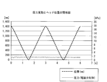
- Example 1 The pressure fluctuation of the inkjet head 5 was confirmed using the inkjet recording apparatus 1A shown in FIG. The result is shown in FIG.
- FIG. 4 is a diagram illustrating the relationship between the pressure fluctuation in the inkjet head 5 and the position of the inkjet head 5.
- the ink jet recording apparatus having the above-described comparative configuration was used as the ink jet recording apparatus of this comparative example, and the pressure fluctuation in the ink jet head provided in the apparatus was confirmed. The result is shown in FIG.
- the ink jet recording apparatus of the comparative example does not have the pressure adjustment mechanism and the electromagnetic valve provided in the ink jet recording apparatus 1A of the first embodiment, and the ink jet recording has a configuration in which the ink cartridge and the ink jet head are directly connected. Device.
- FIG. 2 is a diagram showing the relationship between the pressure fluctuation in the ink jet head and the position of the ink jet head by the ink jet recording apparatus of the comparative example.
- the solid line indicates the pressure fluctuation in the inkjet head
- the broken line indicates the position of the inkjet head.
- the horizontal axis indicates time (seconds).
- the ink jet head was positioned at the leftmost end on the reciprocating movement path at the start of measurement, and reached the rightmost end after 1.5 seconds and then reciprocated back and forth to the leftmost after 1.5 seconds.
- acceleration and deceleration were performed before and after reaching the leftmost end and the rightmost end.
- the straight line portion between them indicates that the inkjet head is moving at a constant speed.
- the solenoid valve used in the present invention needs to be configured so that the meniscus in the nozzle is not destroyed during the opening / closing operation.
- an electromagnetic valve whose pressure fluctuation during opening and closing is ⁇ 5/100 atm (about 5 KPa) or less.
- the electromagnetic valve 4 is disposed downstream of the pressure adjusting mechanism 3, and thereby the ink in the second ink supply tube 6b. Since the influence of the pressure wave and the influence of the pressure fluctuation generated in the pressure adjusting mechanism 3 (ink reservoir 3a) were blocked upstream of the inkjet head 5 and did not reach the inkjet head 5, the inkjet of the comparative example It was shown that the pressure fluctuation in the inkjet head 5 can be effectively suppressed as compared with the recording apparatus.
- the present invention can be suitably used for an ink jet recording apparatus.
- Inkjet recording device (supply channel blocking device) 2 Ink cartridge (ink supply unit) DESCRIPTION OF SYMBOLS 3 Pressure adjustment mechanism 3a Ink storage part 4 Solenoid valve 5 Inkjet head 6a 1st ink supply tube 6a '1st ink supply tube (upper ink supply flow path) 6a′c annular portion 6b second ink supply tube 6c third ink supply tube 10 recording medium
Landscapes
- Ink Jet (AREA)
Abstract
インクジェットヘッドの圧力変動を抑制した供給流路遮断装置および供給流路遮断制御方法を提供することを課題とする。 解決手段として、本発明の一形態であるインクジェット記録装置(1A)は、圧力調整機構(3)とインクジェットヘッド(5)とを繋ぐインク供給チューブに電磁弁(4)が配設されており、往復移動中のインクジェットヘッド(5)の加減速時に上記インク供給チューブを電磁弁(4)によって閉鎖する一方、インクジェットヘッド(5)がインク吐出状態にあるときに上記インク供給チューブを開放する。
Description
本発明は供給流路遮断装置および供給流路遮断制御方法に関し、より具体的には、往復移動するインクジェットヘッドと、当該インクジェットヘッドの往復移動の加減速時にインク供給流路を遮断する機構とを具備する供給流路遮断装置および供給流路遮断制御方法に関する。
インクジェット記録装置は、所定のタイミングでインクジェットヘッドからインク滴を吐出して被記録媒体表面に着滴させることによって画像形成を行う構成となっている。また、インクジェット記録装置の多くは、インクジェットヘッドを被記録媒体表面上で所定の走査方向に往復移動させる機構を備えており、その往復移動の途中でインク滴の吐出がおこなわれる構成となっている。
このようにインクジェットヘッドが往復移動する構成の場合、インクジェットヘッドと、当該インクジェットヘッドにインクを供給するインク供給タンクとの間を結ぶインク供給チューブ内には、往復移動に伴ってインク供給チューブ内のインクの慣性によって圧力波が発生することが知られている。インクの圧力波がインクジェットヘッドに到達すると、インク吐出に悪影響を与える。
そこで、従来より、この往復移動に伴う圧力波の影響を抑える機構を搭載したインクジェット記録装置が知られている。
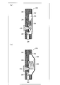
例えば、図5は、特許文献1に記載されているインクジェット記録装置の部分断面図である。図5は、インクジェットヘッドとインク供給チューブとの間に介在させた圧力緩衝器220を示しており、この圧力緩衝器220は、圧力緩衝器本体201と、圧力緩衝膜202と、圧力緩衝器本体201および圧力緩衝膜202に囲まれた領域に形成されるインク貯留部203と、インク貯留部203より上流側のインク流路に配置された電磁弁209と、インク貯留部203内の圧力を測定する圧力センサ210とを備えている(インクの流れを207で示す)。この圧力緩衝器220は、インクジェットヘッドからインクが吐出されてインク貯留部203内の圧力が低下すると、圧力緩衝膜202および負圧感知部材205が弾性部材204を押し付けるように移動し、これを圧力センサ210が感知して電磁弁209を開放状態にする(図5の(a))。また、インクジェットヘッドからのインク吐出が停止すると、圧力センサ210で圧力を測定しながら一定の圧力に回復するまで電磁弁209を開放状態にし、インク貯留部203内の圧力が元に戻ると電磁弁209を閉鎖する(図5の(b))。往復移動の際に圧力波が最も大きくなる瞬間は、インク供給チューブが伸びきった状態での加速時と減速時であるが、一般的に加減速時にはインク吐出はおこなわない。このように、インクジェットヘッドがインクを吐出するときだけインク流路を連通させることで、先述の圧力波の影響を軽減する構造となっている。
しかしながら、上述の特許文献1の構成は、電磁弁209を、圧力緩衝器220のインク貯留部203よりも上流側に設けている。そのため、インクジェットヘッドの往復移動に伴って圧力緩衝器220内の圧力が変動した場合には、その変動がインクジェットヘッドに伝わるという問題がある。
そこで、本発明は上記の問題点に鑑みてなされたものであり、その目的は、インクジェットヘッドの往復移動に伴ってインクジェットヘッドよりも上流において発生する圧力波(圧力変動)が、インクジェットヘッドに影響しない供給流路遮断装置および供給流路遮断制御方法を提供することにある。
上記の課題を解決するために、本発明に係る供給流路遮断装置は、往復移動可能なインクジェットヘッドと、インク貯留部を有し、上記インクジェットヘッドに供給されるインクの圧力を当該インク貯留部において調整する圧力調整機構と、上記インク貯留部と上記インクジェットヘッドとを繋ぐインク供給流路とを備え、往復移動中のインクジェットヘッドの加減速時に上記インク供給流路を閉鎖する一方、インクジェットヘッドがインク吐出状態にあるときに上記インク供給流路を開放可能な弁を上記インク貯留部よりもインク流路方向の下流に備えていることを特徴としている。
上記の構成によれば、インクジェットヘッドと圧力調整機構との間にインク供給流路の開放と閉鎖をおこなう弁を備えている。これにより、インクジェットヘッドの往復移動に伴って圧力調整機構内(具体的にはインク貯留部内)の圧力が変動した場合であって、その変動がインクジェットヘッドに伝わらない。よって、往復移動によるインクジェットヘッド内のインクの圧力変動が効果的に抑制され、インクジェットヘッドを最適に負圧制御することができて、インクジェットヘッドのノズル面においてメニスカスの破壊が生じず、信頼性の高いインク吐出を実現することができる。
本発明に係る供給流路遮断制御装置は、上記の構成に加えて、往復移動中のインクジェットヘッドの加減速時に上記インク供給流路を閉鎖し、インクジェットヘッドがインク吐出状態にあるときに上記インク供給流路を開放するように上記弁を制御する制御手段を更に備えていることが好ましい。
上記の構成によれば、制御手段によって弁を制御してインク供給流路を閉鎖と開放とを調整することができる。
本発明に係る供給流路遮断制御装置は、上記の構成に加えて、上記弁は、電圧印加によって上記インク供給流路の開放と閉鎖をおこなう電磁弁であることが好ましい。
上記の構成によれば、電磁弁を用いることによって、確実かつ簡易にインク供給流路の閉鎖と開放を実現することができる。
本発明に係る供給流路遮断制御装置は、上記の構成に加えて、上記圧力調整機構にインクを供給するインク供給部と、上記インク供給部と上記圧力調整機構とを繋ぐ上部インク供給流路とを更に備え、上記上部インク供給流路は途中で二股に分かれることにより形成された環状部を有していることが好ましい。
上記の構成によれば、上部インク供給流路を環状にすることによって、圧力変動が環状部内でキャンセルされることから、インクジェットヘッドの圧力変動をより一層効果的に抑制することができる。
また、本発明に係る供給流路遮断制御装置は、上記の構成に加えて、開閉時における圧力変動が±5/100気圧以下である電磁弁を用いることが好ましい。
上記の構成によれば、圧力変動が比較的小さい電磁弁を用いることにより、インクジェットヘッドを最適に負圧制御することができ、より一層信頼性の高いインク吐出を実現することができる。
上記の課題を解決するために、本発明に係る供給流路遮断制御方法は、往復移動可能なインクジェットヘッドと、インク貯留部を有し、上記インクジェットヘッドに供給されるインクの圧力を当該インク貯留部において調整する圧力調整機構と、上記インク貯留部と上記インクジェットヘッドとを繋ぐインク供給流路と、上記インク貯留部よりもインク流路方向の下流に設けられた、上記インク供給流路を閉鎖可能な弁とを備えた供給流路遮断装置においておこなわれる供給流路遮断制御方法であって、往復移動中のインクジェットヘッドの加減速時に上記インク供給流路が閉鎖されるよう上記弁を制御し、インクジェットヘッドがインク吐出状態にあるときに上記インク供給流路を開放するように当該弁を制御することを特徴としている。
上記の構成によれば、インクジェットヘッドと圧力調整機構との間にインク供給流路の開放と閉鎖をおこなう弁を備えている。これにより、インクジェットヘッドの往復移動に伴って圧力調整機構内(具体的にはインク貯留部内)の圧力が変動した場合であって、その変動がインクジェットヘッドに伝わらない。よって、往復移動によるインクジェットヘッド内のインクの圧力変動が効果的に抑制され、インクジェットヘッドを最適に負圧制御することができて、インクジェットヘッドのノズル面においてメニスカスの破壊が生じず、信頼性の高いインク吐出を実現することができる。
本発明によれば、インクジェットヘッドの往復移動に伴ってインクジェットヘッドよりも上流において発生する圧力波(圧力変動)が、インクジェットヘッドに影響しない供給流路遮断装置および供給流路遮断制御方法を提供することができる。
〔実施形態1〕
以下、本発明に係る供給流路遮断装置および供給流路遮断制御方法の一実施形態について、図1を用いて説明する。なお、本実施形態では、本発明に係る供給流路遮断装置の一例であるインクジェット記録装置に基づいて説明する。
以下、本発明に係る供給流路遮断装置および供給流路遮断制御方法の一実施形態について、図1を用いて説明する。なお、本実施形態では、本発明に係る供給流路遮断装置の一例であるインクジェット記録装置に基づいて説明する。
図1は、本実施形態1のインクジェット記録装置1A(供給流路遮断装置)の構成を示す図である。
インクジェット記録装置1Aは、インクカートリッジ2(インク供給部)と、圧力調整機構3と、電磁弁4(弁)と、インクジェットヘッド5とを備え、この順でインクが流れる。すなわち、これらのうちのインクカートリッジ2が最も上流に在って、インクカートリッジ2と圧力調整機構3とは第一のインク供給チューブ6aによって繋がっており、圧力調整機構3とインクジェットヘッド5とを繋ぐインク供給チューブに電磁弁4が配設されている。なお、説明の便宜上、圧力調整機構3と電磁弁4との間のインク供給チューブを第二のインク供給チューブ6bと称し、電磁弁4とインクジェットヘッド5との間のインク供給チューブを第三のインク供給チューブ6cと称することとする。
インクカートリッジ2は、従来周知のインクカートリッジであり、図示しないカートリッジホルダに設置して、第一のインク供給チューブ6aを介して圧力調整機構3へインクを供給する。
圧力調整機構3は、インク貯留部3aを有し、第一のインク供給チューブ6aからインクカートリッジ2のインクがインク貯留部3aへ供給されて一時貯留される。
ここで、第一のインク供給チューブ6aは、インクジェットヘッド5の往復移動に併せてインクカートリッジ2よりも下流の構成部材が往復移動できるように十分な余長を有している。
圧力調整機構3は、インクジェットヘッド5に供給されたインクが、インクジェットヘッド5内において所定の圧力で保持されるために、インク貯留部3aにおいてインクの圧力を調整する。具体的には、インクジェットヘッド5からインクが吐出されない状態(非吐出状態)では、圧力調整機構3が、インクジェットヘッド5内のインクを負圧に保ち、インクジェットヘッド5からインクが漏れ出ることを防ぐ。一方、インクジェットヘッド5からインクが吐出されている状態(吐出状態)では、インクジェットヘッド5においてインクがメニスカスを形成して、外部から入手した印刷データに基づいて所定のタイミングで吐出されるように圧力を調整している。圧力調整機構3による圧力の調整は、圧力調整機構3のインク貯留部3aの容積を変化させることによって実現することができる。なお、圧力調整方法は、この方法に限定されるものではない。
電磁弁4は、圧力調整機構3よりもインク供給方向の下流に在って、圧力調整機構3(インク貯留部3a)とインクジェットヘッド5との間のインク供給流路(インク供給チューブ)を閉塞したり開放したりする弁である。詳細は後述するが、電磁弁4は、図示しない制御手段から弁駆動部が信号を受信し、弁駆動部が電磁弁4に電圧を印加して閉鎖と開放を制御する。
ここで、この制御手段としては、後述するような電磁弁4の閉鎖と開放との切り替えを実現することができれば、制御方法(供給流路遮断制御方法)に制限はない。例えば、図示しない位置センサによって往復移動するインクジェットヘッド5の位置をセンシングし、その位置センサから送出される信号が上記制御信号となって電磁弁4の閉鎖と開放との切り替えをおこなうことができる。
ほかには、インクジェットヘッド5が往復移動を開始してからいつの時点で往復移動経路の端部に到達するかや、いつの時点およびどのくらいの期間加速するかあるいは減速するかのタイミングチャートを把握することができるので、これに基づいて、電磁弁4を閉鎖するタイミングと、閉鎖する期間と、電磁弁4を開放するタイミングを予め求めて、そのタイミングに合わせて制御信号を弁駆動部に送出して、電磁弁4への電圧印加タイミングを制御することも可能である。
更に別の態様として、圧力変動センサを、インクカートリッジ2、圧力調整機構3、インクジェットヘッド5、あるいはインク供給チューブ(第一~第三のインク供給チューブ6a~6c)の少なくとも一箇所に配設し、圧力変動を検知すると、圧力変動センサから制御信号が弁駆動部に送出されて、電磁弁4への電圧印加が制御されてもよい。
インクジェットヘッド5は、図示しない移動機構およびガイド手段によって、往復移動する構成となっている。例えば、インクジェットヘッド5から滴下されるインク滴の着弾対象である被記録媒体10(例えば紙やフィルムなど)を副走査方向に移動させる場合に、インクジェットヘッド5は副走査方向に直交する主走査方向に移動し、移動中にインク滴を所定のタイミングで被記録媒体表面に滴下することによって、被記録媒体表面に所望の画像を形成することができる。
ここで本実施形態1は、インクジェットヘッド5の移動に伴って、インクカートリッジ2よりも下流の構成部材が全てインクジェットヘッド5とともに移動する。そのため、往復移動に伴ってインク供給チューブ内のインクの慣性によって圧力波が発生する。このインクの圧力波が仮にインクジェットヘッド5に到達するとメニスカス破壊が生じ、正圧がかかるとインクジェットヘッド5のインク吐出孔から不都合にインクが漏れ出る事態となり、負圧がかかると逆にインク吐出孔からインクが引き上がってヘッド内に空気が入るなど、インク吐出に悪影響を与えてしまう。そこで、本実施形態1では、そのような悪影響を電磁弁4によって解消する。
特に本実施形態1では、電磁弁4の配設位置を、圧力調整機構3(インク貯留部3a)とインクジェットヘッド5との間にすることにより、圧力調整機構3(インク貯留部3a)内で生じる圧力変動が、インクジェットヘッド5のインクに及ぶことがなく、インクジェットヘッド内のインクの圧力変動を効果的に抑制して、安定したインク吐出を実現するインクジェット記録装置1Aを提供することができる。
なお、本実施形態1のインクジェット記録装置1Aと、本発明の範囲外である比較構成のインクジェット記録装置とを用いてインクジェットヘッド内のインクの圧力変動の抑制効果を対比した結果を、後述する実施例および比較例に示す。比較構成のインクジェット記録装置と、本実施形態1のインクジェット記録装置1Aとの違いは、比較構成のインクジェット記録装置は、圧力調整機構も電磁弁も無い点にある。すなわち、比較構成のインクジェット記録装置は、インクカートリッジとインクジェットヘッドとが、直接、繋がっている。
後述する実施例からわかるように、本実施形態1のインクジェット記録装置1Aによれば、比較構成のインクジェット記録装置に比べ、インクジェットヘッド5内の圧力変動を効果的に抑制することができていることがわかる。
両者に効果の違いが生じる理由は、圧力調整機構および電磁弁の配設の有無によるものである。すなわち、比較構成のインクジェット記録装置の場合、インクジェットヘッド内に圧力変動を生じさせる。これに対して、本実施形態1のインクジェット記録装置1Aによれば、圧力調整機構3を配設するだけでなく、圧力調整機構3よりも下流に電磁弁4を配設したことにより、第二のインク供給チューブ6bのインクの圧力波による影響、および、圧力調整機構3(インク貯留部3a)内に生じた圧力変動による影響が、インクジェットヘッド5の上流で遮断されて、インクジェットヘッド5に及ばないようにすることができる。
なお、本発明の範囲外であるが、本実施形態1のインクジェット記録装置1Aから電磁弁4だけを除いた構成であっても、先述の比較構成のインクジェット記録装置に比べ、インクジェットヘッド内の圧力変動を抑制することができる。しかしながら、本実施形態1のように圧力調整機構3とインクジェットヘッド5との間に電磁弁4を配設することによって、圧力調整機構3(インク貯留部3a)内に生じた圧力変動がインクジェットヘッド5に及ばないようにすることができる。後述の実施例に示すように本実施形態1のインクジェット記録装置1Aの構成によれば、インクジェットヘッド5の圧力変動を完全に抑えることができ、本実施形態1の構成は優位な構成であるといえる。
本実施形態1の最後に、電磁弁4の閉鎖期間と開放期間(電磁弁4の制御方法)について説明する。電磁弁4は、インクジェットヘッド5が加減速期間中に閉鎖されるが、当該加減速期間の前後に僅かに閉鎖期間が延びている。ここで、インクジェットヘッド5は定速移動中に印字をおこなうが、定速期間中における、加速期間から定速期間に突入した直後の所定の期間、および、定速期間から減速期間に移行する直前の所定の期間は、印字をおこなわない。そこで、電磁弁4は、印字期間を除いた期間、閉鎖する。すなわち、電磁弁4が閉鎖している期間の一部には、インクジェットヘッド5が定速移動している期間が含まれる。
このように、加減速期間だけでなく加減速期間の前後に電磁弁4の閉鎖期間を延ばすことによって、圧力調整機構3(インク貯留部3a)および圧力調整機構3より上流に生じた圧力変動が、インクジェットヘッド5に影響することをより一層しっかり抑制することができる。
〔変形例〕
上記実施形態1では、圧力調整機構3とインクジェットヘッド5との間に配されているチューブの途中に電磁弁4を設けた態様を説明したが、インクジェットヘッド5の圧力変動を抑制するという本発明の目的からすると、電磁弁4の位置は、インクジェットヘッド5のインク供給口に在ってもよい。この変形例も本発明の範囲に含まれる。
上記実施形態1では、圧力調整機構3とインクジェットヘッド5との間に配されているチューブの途中に電磁弁4を設けた態様を説明したが、インクジェットヘッド5の圧力変動を抑制するという本発明の目的からすると、電磁弁4の位置は、インクジェットヘッド5のインク供給口に在ってもよい。この変形例も本発明の範囲に含まれる。
また、更なる変形例として、インクジェットヘッド5のインク供給口に電磁弁4を設け、更に、上記実施形態1のインクジェット記録装置1Aの圧力調整機構3とインクジェットヘッド5との間に配設されているインク供給チューブを使用せずに圧力調整機構3と、インク供給口に電磁弁4を設けたインクジェットヘッド5とを、直接、繋いだ構成であってもよい。この変形例もまた本発明の範囲に含まれる。
〔実施形態2〕
本発明に係る供給流路遮断装置の第2の実施形態について、図3に基づいて説明する。なお、本実施形態2において説明すること以外の構成は、上記実施形態1と同じである。また、説明の便宜上、実施形態1において各図面に示す部材と同一の機能を有する部材については、同一の符号を付し、その説明を省略する。
本発明に係る供給流路遮断装置の第2の実施形態について、図3に基づいて説明する。なお、本実施形態2において説明すること以外の構成は、上記実施形態1と同じである。また、説明の便宜上、実施形態1において各図面に示す部材と同一の機能を有する部材については、同一の符号を付し、その説明を省略する。
図3は、本発明に係る供給流路遮断装置の第2の実施形態の一例であるインクジェット記録装置1Bの構成を示す図である。
本実施形態2と実施形態1との相違点は、インクカートリッジ2と圧力調整機構3との間に配設されたインク供給チューブ(実施形態1における第一のインク供給チューブ6a)の形状にある。
本実施形態2では、図3に示すように、インクカートリッジ2と圧力調整機構3との間に配設された第一のインク供給チューブ6a´(上部インク供給流路)が、途中において分岐して二股となっており、二股が再度合流することで形成された環状部6a´cを有している。このように第一のインク供給チューブ6a´を環状にすることによって、圧力変動が環状部内でキャンセルされることから、インクジェットヘッド5の圧力変動をより一層効果的に抑制することができる。
本発明は上述した各実施形態に限定されるものではなく、請求項に示した範囲で種々の変更が可能であり、異なる実施形態にそれぞれ開示された技術的手段を適宜組み合わせて得られる実施形態についても本発明の技術的範囲に含まれる。
〔付記事項〕
本発明の一形態に係るインクジェット記録装置1A、1Bは、往復移動可能なインクジェットヘッド5と、インク貯留部3aを有し、上記インクジェットヘッド5に供給されるインクの圧力を当該インク貯留部3aにおいて調整する圧力調整機構3と、上記インク貯留部3aと上記インクジェットヘッド5とを繋ぐインク供給流路(第二のインク供給チューブ6bおよび第三のインク供給チューブ6c)とを備え、往復移動中のインクジェットヘッド5の加減速時に上記インク供給流路(第二のインク供給チューブ6bおよび第三のインク供給チューブ6c)を閉鎖する一方、インクジェットヘッドがインク吐出状態にあるときに上記インク供給流路(第二のインク供給チューブ6bおよび第三のインク供給チューブ6c)を開放可能な電磁弁4を上記インク貯留部3aよりもインク流路方向の下流に備えている。
本発明の一形態に係るインクジェット記録装置1A、1Bは、往復移動可能なインクジェットヘッド5と、インク貯留部3aを有し、上記インクジェットヘッド5に供給されるインクの圧力を当該インク貯留部3aにおいて調整する圧力調整機構3と、上記インク貯留部3aと上記インクジェットヘッド5とを繋ぐインク供給流路(第二のインク供給チューブ6bおよび第三のインク供給チューブ6c)とを備え、往復移動中のインクジェットヘッド5の加減速時に上記インク供給流路(第二のインク供給チューブ6bおよび第三のインク供給チューブ6c)を閉鎖する一方、インクジェットヘッドがインク吐出状態にあるときに上記インク供給流路(第二のインク供給チューブ6bおよび第三のインク供給チューブ6c)を開放可能な電磁弁4を上記インク貯留部3aよりもインク流路方向の下流に備えている。
上記の構成によれば、インクジェットヘッド5と圧力調整機構3との間にインク供給流路(第二のインク供給チューブ6bおよび第三のインク供給チューブ6c)の開放と閉鎖をおこなう電磁弁4を備えている。これにより、インクジェットヘッド5の往復移動に伴って圧力調整機構3内(具体的にはインク貯留部内3a)の圧力が変動した場合であって、その変動がインクジェットヘッド5に伝わらない。よって、往復移動によるインクジェットヘッド5内のインクの圧力変動が効果的に抑制され、インクジェットヘッド5を最適に負圧制御することができて、インクジェットヘッド5のノズル面においてメニスカスの破壊が生じず、信頼性の高いインク吐出を実現することができる。
また、本発明の一形態に係るインクジェット記録装置1A、1Bは、上記の構成に加えて、往復移動中のインクジェットヘッド5の加減速時に上記インク供給流路(第二のインク供給チューブ6bおよび第三のインク供給チューブ6c)を閉鎖し、インクジェットヘッドがインク吐出状態にあるときに上記インク供給流路(第二のインク供給チューブ6bおよび第三のインク供給チューブ6c)を開放するように電磁弁4を制御する制御手段を更に備えている。
上記の構成によれば、制御手段によって電磁弁4を制御してインク供給流路(第二のインク供給チューブ6bおよび第三のインク供給チューブ6c)を閉鎖と開放とを調整することができる。
また、本発明の一形態に係るインクジェット記録装置1A、1Bは、上記の構成に加えて、上記電磁弁4は、電圧印加によって上記インク供給流路の開放と閉鎖をおこなう構成となっている。
上記の構成によれば、電磁弁を用いることによって、確実かつ簡易にインク供給流路(第二のインク供給チューブ6bおよび第三のインク供給チューブ6c)の閉鎖と開放を実現することができる。
また、本発明の一形態に係るインクジェット記録装置1Bは、上記の構成に加えて、上記圧力調整機構3にインクを供給するインクカートリッジ2と、上記インクカートリッジ2と上記圧力調整機構3とを繋ぐ第一のインク供給チューブ6a´とを更に備え、上記第一のインク供給チューブ6a´は途中で二股に分かれることにより形成された環状部6a´cを有している。
上記の構成によれば、第一のインク供給チューブ6a´を環状にすることによって、圧力変動が環状部内でキャンセルされることから、インクジェットヘッド5の圧力変動をより一層効果的に抑制することができる。
また、本発明の一形態に係るインクジェット記録装置1A、1Bにおいて、電磁弁4は、開閉時における圧力変動が±5/100気圧以下である。
上記の構成によれば、電磁弁4は圧力変動が比較的小さいことから、インクジェットヘッド5を最適に負圧制御することができ、より一層信頼性の高いインク吐出を実現することができる。
上記の課題を解決するために、本発明に係る供給流路遮断制御方法は、往復移動可能なインクジェットヘッド5と、インク貯留部3aを有し、上記インクジェットヘッド5に供給されるインクの圧力を当該インク貯留部3aにおいて調整する圧力調整機構3と、上記インク貯留部3aと上記インクジェットヘッド5とを繋ぐインク供給流路(第二のインク供給チューブ6bおよび第三のインク供給チューブ6c)と、上記インク貯留部3aよりもインク流路方向の下流に設けられた、上記インク供給流路(第二のインク供給チューブ6bおよび第三のインク供給チューブ6c)を閉鎖可能な電磁弁4とを備えたインクジェット記録装置1A、1Bにおいておこなわれる供給流路遮断制御方法であって、往復移動中のインクジェットヘッド5の加減速時に上記インク供給流路が閉鎖されるよう上記電磁弁4を制御し、インクジェットヘッド5がインク吐出状態にあるときに上記インク供給流路を開放するように当該電磁弁4を制御する。
上記の構成によれば、インクジェットヘッド5と圧力調整機構3との間にインク供給流路(第二のインク供給チューブ6bおよび第三のインク供給チューブ6c)の開放と閉鎖をおこなう電磁弁4を備えている。これにより、インクジェットヘッド5の往復移動に伴って圧力調整機構3内(具体的にはインク貯留部3a内)の圧力が変動した場合であって、その変動がインクジェットヘッド5に伝わらない。よって、往復移動によるインクジェットヘッド5内のインクの圧力変動が効果的に抑制され、インクジェットヘッド5を最適に負圧制御することができて、インクジェットヘッド5のノズル面においてメニスカスの破壊が生じず、信頼性の高いインク吐出を実現することができる。
〔実施例1〕
図1に示すインクジェット記録装置1Aを用いてインクジェットヘッド5の圧力変動を確認した。その結果を図4に示す。図4は、インクジェットヘッド5内の圧力変動と、インクジェットヘッド5の位置との関係を示す図である。
図1に示すインクジェット記録装置1Aを用いてインクジェットヘッド5の圧力変動を確認した。その結果を図4に示す。図4は、インクジェットヘッド5内の圧力変動と、インクジェットヘッド5の位置との関係を示す図である。
図4をみると、インクジェットヘッド5が最左端および最右端に到達した時点およびその前後わずかな期間に、電磁弁4を閉鎖することにより、電磁弁4の閉鎖期間においてインクジェットヘッド5内に大きな圧力変動は見られないことがわかる。
〔比較例1〕
先述した比較構成のインクジェット記録装置を本比較例のインクジェット記録装置として用いて、当該装置に具備されたインクジェットヘッド内の圧力変動を確認した。その結果を図2に示す。なお、比較例のインクジェット記録装置とは、本実施形態1のインクジェット記録装置1Aに設けられている圧力調整機構および電磁弁が無く、インクカートリッジとインクジェットヘッドとが、直接、繋がった構成のインクジェット記録装置である。
先述した比較構成のインクジェット記録装置を本比較例のインクジェット記録装置として用いて、当該装置に具備されたインクジェットヘッド内の圧力変動を確認した。その結果を図2に示す。なお、比較例のインクジェット記録装置とは、本実施形態1のインクジェット記録装置1Aに設けられている圧力調整機構および電磁弁が無く、インクカートリッジとインクジェットヘッドとが、直接、繋がった構成のインクジェット記録装置である。
図2は、比較例のインクジェット記録装置による、インクジェットヘッド内の圧力変動と、インクジェットヘッドの位置との関係を示す図である。図2中において、実線がインクジェットヘッド内の圧力変動を示し、破線がインクジェットヘッドの位置を示す。横軸は時間(秒)を示す。インクジェットヘッドは計測開始時点で往復移動経路上の最左端に位置しており、1.5秒後に最右端へ到達し、そこから1.5秒後に最左端に戻るという往復移動を繰り返した。また、最左端および最右端に到達する前後では加速と減速とが行われた。一方、その間の直線部分はインクジェットヘッドが定速で移動していることを示す。その結果、図2に示すように、インクジェットヘッドが最左端および最右端に到達した時点およびその前後わずかな期間に、インクジェットヘッド内の圧力が変動していることがわかった。具体的には、インクジェットヘッドが最左端に到達した時点とその前後においてインクジェットヘッド内に比較的大きな正圧がかかっていることがわかった。一方、インクジェットヘッドが最右端に到達した時点とその前後においてインクジェットヘッド内に比較的大きな負圧がかかっていることがわかった。すなわち、比較例のインクジェット記録装置は、インクジェットヘッド内の圧力変動を効果的に抑制することができていないことがわかった。
なお、本発明に使用する電磁弁は、開閉動作時にノズル内でのメニスカスが破壊されないように構成する必要がある。例えば、開閉時における圧力変動が±5/100気圧(約5KPa)以下である電磁弁を用いることが好ましい。
以上のように、比較例のインクジェット記録装置の場合、インクジェットヘッドの往復移動に伴ってインクジェットヘッド内に圧力変動を生じさせている。これに対して、実施形態1の構成である実施例のインクジェット記録装置1Aによれば、圧力調整機構3よりも下流に電磁弁4を配設したことにより、第二のインク供給チューブ6bのインクの圧力波による影響、および、圧力調整機構3(インク貯留部3a)内に生じた圧力変動による影響が、インクジェットヘッド5の上流で遮断されてインクジェットヘッド5に及ばなかったために、比較例のインクジェット記録装置に比べ、インクジェットヘッド5内の圧力変動を効果的に抑制することができていることが示された。
本発明は、インクジェット記録装置に好適に利用することができる。
1A、1B インクジェット記録装置(供給流路遮断装置)
2 インクカートリッジ(インク供給部)
3 圧力調整機構
3a インク貯留部
4 電磁弁
5 インクジェットヘッド
6a 第一のインク供給チューブ
6a´ 第一のインク供給チューブ(上部インク供給流路)
6a´c 環状部
6b 第二のインク供給チューブ
6c 第三のインク供給チューブ
10 被記録媒体
2 インクカートリッジ(インク供給部)
3 圧力調整機構
3a インク貯留部
4 電磁弁
5 インクジェットヘッド
6a 第一のインク供給チューブ
6a´ 第一のインク供給チューブ(上部インク供給流路)
6a´c 環状部
6b 第二のインク供給チューブ
6c 第三のインク供給チューブ
10 被記録媒体
Claims (6)
- 往復移動可能なインクジェットヘッドと、
インク貯留部を有し、上記インクジェットヘッドに供給されるインクの圧力を当該インク貯留部において調整する圧力調整機構と、
上記インク貯留部と上記インクジェットヘッドとを繋ぐインク供給流路とを備え、
往復移動中のインクジェットヘッドの加減速時に上記インク供給流路を閉鎖する一方、インクジェットヘッドがインク吐出状態にあるときに上記インク供給流路を開放可能な弁を上記インク貯留部よりもインク流路方向の下流に備えていることを特徴とする供給流路遮断装置。 - 往復移動中のインクジェットヘッドの加減速時に上記インク供給流路を閉鎖し、インクジェットヘッドがインク吐出状態にあるときに上記インク供給流路を開放するように上記弁を制御する制御手段を更に備えていることを特徴とする請求項1に記載の供給流路遮断装置。
- 上記弁は、電圧印加によって上記インク供給流路の開放と閉鎖をおこなう電磁弁であることを特徴とする請求項1に記載の供給流路遮断装置。
- 上記圧力調整機構にインクを供給するインク供給部と、
上記インク供給部と上記圧力調整機構とを繋ぐ上部インク供給流路とを更に備え、
上記上部インク供給流路は途中で二股に分かれることにより形成された環状部を有していることを特徴とする請求項1から3までの何れか1項に記載の供給流路遮断装置。 - 上記電磁弁は、開閉時における圧力変動が±5/100気圧以下であることを特徴とする請求項3に記載の供給流路遮断装置。
- 往復移動可能なインクジェットヘッドと、
インク貯留部を有し、上記インクジェットヘッドに供給されるインクの圧力を当該インク貯留部において調整する圧力調整機構と、
上記インク貯留部と上記インクジェットヘッドとを繋ぐインク供給流路と、
上記インク貯留部よりもインク流路方向の下流に設けられた、上記インク供給流路を閉鎖可能な弁とを備えた供給流路遮断装置においておこなわれる供給流路遮断制御方法であって、
往復移動中のインクジェットヘッドの加減速時に上記インク供給流路が閉鎖されるよう上記弁を制御し、インクジェットヘッドがインク吐出状態にあるときに上記インク供給流路を開放するように当該弁を制御する供給流路遮断制御方法。
Applications Claiming Priority (2)
| Application Number | Priority Date | Filing Date | Title |
|---|---|---|---|
| JP2013210581A JP2015074125A (ja) | 2013-10-07 | 2013-10-07 | 供給流路遮断装置および供給流路遮断制御方法 |
| JP2013-210581 | 2013-10-07 |
Publications (1)
| Publication Number | Publication Date |
|---|---|
| WO2015053155A1 true WO2015053155A1 (ja) | 2015-04-16 |
Family
ID=52812971
Family Applications (1)
| Application Number | Title | Priority Date | Filing Date |
|---|---|---|---|
| PCT/JP2014/076327 Ceased WO2015053155A1 (ja) | 2013-10-07 | 2014-10-01 | 供給流路遮断装置および供給流路遮断制御方法 |
Country Status (2)
| Country | Link |
|---|---|
| JP (1) | JP2015074125A (ja) |
| WO (1) | WO2015053155A1 (ja) |
Cited By (1)
| Publication number | Priority date | Publication date | Assignee | Title |
|---|---|---|---|---|
| CN109664618A (zh) * | 2017-10-16 | 2019-04-23 | 北大方正集团有限公司 | 供墨控制系统、印刷机、供墨控制方法 |
Families Citing this family (1)
| Publication number | Priority date | Publication date | Assignee | Title |
|---|---|---|---|---|
| KR101937349B1 (ko) * | 2016-10-27 | 2019-01-10 | 세메스 주식회사 | 약액 공급 장치 및 이를 포함하는 약액 토출 장치 |
Citations (4)
| Publication number | Priority date | Publication date | Assignee | Title |
|---|---|---|---|---|
| JPS5896562A (ja) * | 1981-12-04 | 1983-06-08 | Matsushita Electric Ind Co Ltd | インク供給装置 |
| JP2004114411A (ja) * | 2002-09-25 | 2004-04-15 | Canon Inc | インク供給装置及びインク供給方法 |
| JP2005288932A (ja) * | 2004-04-01 | 2005-10-20 | Canon Inc | インクジェット記録装置 |
| JP2006188072A (ja) * | 2006-04-03 | 2006-07-20 | Ricoh Co Ltd | 印字装置 |
-
2013
- 2013-10-07 JP JP2013210581A patent/JP2015074125A/ja active Pending
-
2014
- 2014-10-01 WO PCT/JP2014/076327 patent/WO2015053155A1/ja not_active Ceased
Patent Citations (4)
| Publication number | Priority date | Publication date | Assignee | Title |
|---|---|---|---|---|
| JPS5896562A (ja) * | 1981-12-04 | 1983-06-08 | Matsushita Electric Ind Co Ltd | インク供給装置 |
| JP2004114411A (ja) * | 2002-09-25 | 2004-04-15 | Canon Inc | インク供給装置及びインク供給方法 |
| JP2005288932A (ja) * | 2004-04-01 | 2005-10-20 | Canon Inc | インクジェット記録装置 |
| JP2006188072A (ja) * | 2006-04-03 | 2006-07-20 | Ricoh Co Ltd | 印字装置 |
Cited By (1)
| Publication number | Priority date | Publication date | Assignee | Title |
|---|---|---|---|---|
| CN109664618A (zh) * | 2017-10-16 | 2019-04-23 | 北大方正集团有限公司 | 供墨控制系统、印刷机、供墨控制方法 |
Also Published As
| Publication number | Publication date |
|---|---|
| JP2015074125A (ja) | 2015-04-20 |
Similar Documents
| Publication | Publication Date | Title |
|---|---|---|
| US7976140B2 (en) | Liquid droplet ejecting apparatus | |
| US8485620B2 (en) | Inkjet printer and bubble reducing method for inkjet printer | |
| JP5413229B2 (ja) | 液体噴射装置 | |
| CN115413259A (zh) | 喷墨记录装置 | |
| WO2015053155A1 (ja) | 供給流路遮断装置および供給流路遮断制御方法 | |
| JP2010012707A (ja) | 背圧維持装置及びインクジェット記録装置 | |
| CN104411499B (zh) | 喷墨打印装置、液体供给装置以及打印头的清洁方法 | |
| JP6666761B2 (ja) | インク供給システムおよびインクジェットプリンタ | |
| JP5679034B2 (ja) | 液体噴射装置 | |
| JP5493796B2 (ja) | 液体噴射装置 | |
| JP2009083387A (ja) | 記録液供給装置及び画像形成装置 | |
| JP4344713B2 (ja) | インクカートリッジ及びインクジェット記録システム | |
| JP5212192B2 (ja) | 画像形成装置 | |
| JP2010221460A (ja) | 流体噴射装置 | |
| JP2011178016A (ja) | 液体噴射装置 | |
| JP2018126917A (ja) | 流体吐出ヘッドおよび流体吐出装置 | |
| US20150273852A1 (en) | Inkjet printer | |
| JP3869171B2 (ja) | インク供給機構及びインクジェット印字装置 | |
| JP5024471B2 (ja) | 液体吐出装置および液体吐出ヘッド | |
| JP4962627B2 (ja) | 液体吐出装置および液体吐出ヘッド | |
| JP3862744B2 (ja) | 印字装置 | |
| JP2012106462A (ja) | インクジェット記録装置及びそのクリーニング方法 | |
| JP2008201077A (ja) | 圧力緩衝器及びインクジェットヘッド | |
| JP2026071972A (ja) | 印刷装置、及び、インク供給ユニット | |
| WO2026083744A1 (ja) | 印刷装置、及び、インク供給ユニット |
Legal Events
| Date | Code | Title | Description |
|---|---|---|---|
| 121 | Ep: the epo has been informed by wipo that ep was designated in this application |
Ref document number: 14852795 Country of ref document: EP Kind code of ref document: A1 |
|
| NENP | Non-entry into the national phase |
Ref country code: DE |
|
| 122 | Ep: pct application non-entry in european phase |
Ref document number: 14852795 Country of ref document: EP Kind code of ref document: A1 |